recommended guanidine suppressor for the next-generation caustic
TRANSCRIPT

ORNL/TM-2012/625
Recommended Guanidine Suppressor for the Next-Generation Caustic-Side Solvent Extraction Process
January 2013 Prepared by Bruce A. Moyer, Lætitia H. Delmau, Nathan C. Duncan, Dale D. Ensor, Talon G. Hill, Denise L. Lee, Benjamin D. Roach, Frederick V. Sloop, Jr., and Neil J. Williams

DOCUMENT AVAILABILITY Reports produced after January 1, 1996, are generally available free via the U.S. Department of Energy (DOE) Information Bridge. Web site http://www.osti.gov/bridge Reports produced before January 1, 1996, may be purchased by members of the public from the following source. National Technical Information Service 5285 Port Royal Road Springfield, VA 22161 Telephone 703-605-6000 (1-800-553-6847) TDD 703-487-4639 Fax 703-605-6900 E-mail [email protected] Web site http://www.ntis.gov/support/ordernowabout.htm Reports are available to DOE employees, DOE contractors, Energy Technology Data Exchange (ETDE) representatives, and International Nuclear Information System (INIS) representatives from the following source. Office of Scientific and Technical Information P.O. Box 62 Oak Ridge, TN 37831 Telephone 865-576-8401 Fax 865-576-5728 E-mail [email protected] Web site http://www.osti.gov/contact.html
This report was prepared as an account of work sponsored by an agency of the United States Government. Neither the United States Government nor any agency thereof, nor any of their employees, makes any warranty, express or implied, or assumes any legal liability or responsibility for the accuracy, completeness, or usefulness of any information, apparatus, product, or process disclosed, or represents that its use would not infringe privately owned rights. Reference herein to any specific commercial product, process, or service by trade name, trademark, manufacturer, or otherwise, does not necessarily constitute or imply its endorsement, recommendation, or favoring by the United States Government or any agency thereof. The views and opinions of authors expressed herein do not necessarily state or reflect those of the United States Government or any agency thereof.

ORNL/TM-2012/625
Next-Generation CSSX Program
RECOMMENDED GUANIDINE SUPPRESSOR FOR THE NEXT-GENERATION CAUSTIC-SIDE SOLVENT EXTRACTION PROCESS
Bruce A. Moyer, Lætitia H. Delmau, Nathan C. Duncan, Dale D. Ensor, Talon G. Hill, Denise L. Lee, Benjamin D. Roach, Frederick V. Sloop, Jr., and Neil J. Williams
Date Published: January 2013
Prepared by OAK RIDGE NATIONAL LABORATORY
Oak Ridge, Tennessee 37831-6283 managed by
UT-BATTELLE, LLC for the
U.S. DEPARTMENT OF ENERGY under contract DE-AC05-00OR22725

v
CONTENTS
Page CONTENTS ........................................................................................................................................... v LIST OF TABLES ............................................................................................................................... vii LIST OF ABBREVIATED TERMS ..................................................................................................... ix ABSTRACT ........................................................................................................................................... 1 1. INTRODUCTION ........................................................................................................................... 1 2. EXPERIMENTAL SECTION ......................................................................................................... 5
2.1 MATERIALS ....................................................................................................................... 5 2.1.1 Solvent Components ................................................................................................ 5 2.1.2 Guanidine Suppressors ............................................................................................ 5 2.1.3 Waste Simulants and Other Aqueous Solutions ...................................................... 9
2.2 METHODS ......................................................................................................................... 10 2.2.1 Cesium Distribution Ratios in ESS Tests .............................................................. 10 2.2.2 Partitioning of Suppressors into 10 mM Boric Acid ............................................. 11 2.2.3 Third-Phase Formation .......................................................................................... 12 2.2.4 Emulsion Testing ................................................................................................... 13 2.2.5 Interfacial Tension Measurements ........................................................................ 13 2.2.6 Dispersion Number Testing ................................................................................... 14 2.2.7 Thermal Stability Test ........................................................................................... 15
3. RESULTS AND DISCUSSION .................................................................................................... 17 3.1 ESS TESTING OF SUPPRESSOR CANDIDATES ......................................................... 17 3.2 PARTITIONING OF SUPPRESSOR INTO BORIC ACID .............................................. 19 3.3 THIRD-PHASE TEST RESULTS ..................................................................................... 19 3.4 EMULSION TESTING ...................................................................................................... 20 3.5 INTERFACIAL TENSION TEST RESULTS ................................................................... 20 3.6 DISPERSION NUMBERS ................................................................................................. 21
3.6.1 Thermal Stability Test ........................................................................................... 24 CONCLUSIONS .................................................................................................................................. 27 ACKNOWLEDGMENTS .................................................................................................................... 28 4. REFERENCES .............................................................................................................................. 29


vii
LIST OF TABLES Table Page 1. NG-CSSX Solvent Components ......................................................................................................... 2 2. Guanidine Candidates Tested for NGS .............................................................................................. 4 3. Aqueous Tank-Waste Simulants with Abbreviated Names Indicated ................................................ 9 4. Cesium Distribution Ratios for ESS Batch Tests for Each of the Suppressor Candidates ............... 18 5. Cesium Distribution Ratios for ESS Batch Tests for Each of the Suppressor Candidates Stressed by
Addition of SDS to the Waste Simulant ........................................................................................ 18 6. Guanidine Partition Ratios for NG-CSSX Solvent in Contact with 10 mM Boric Acid Strip
Solution at 25 °C ............................................................................................................................ 19 7. Third-Phase Test Results for Solvent Contacts with Boric Acid Strip Solution .............................. 20 8. Emulsion Test Results for NGS Candidate Solvents in Contact with 20 mM Boric Acid ............... 20 9. Interfacial Tension of Candidate NG-CSSX Solvents Under ESS Conditions ................................ 21 10. Dispersion Numbers for Various Guanidine Suppressors .............................................................. 23 11. Cesium Distribution Ratios for ESS Batch Tests for Thermally Treated Solvents Containing TiDG
and DCiTG ..................................................................................................................................... 25


ix
LIST OF ABBREVIATED TERMS BiTABG N,N'-Bis(isotridecyl)-N"-(4-t-amylbenzyl)guanidine Cs-7SB Modifier 1-(2,2,3,3-tetrafluoropropoxy)-3-(4-sec-butylphenoxy)-2-propanol CSSX Caustic-Side Solvent Extraction DCiTG N,N'-Dicyclohexyl-N"-isotridecylguanidine DF Decontamination factor DOE U.S. Department of Energy ESS Extract/scrub/strip ES2S3 Extract/scrub 2x/strip 3x GC Gas chromatography HPLC High performance liquid chromatography LIX®-79 Commercial (Cognis) guanidine-containing extractant mixture MaxCalix Extractant 1,3-alt-25,27-bis(3,7-dimethyloctyl-1-oxy) calix[4]arene-benzocrown-6 MCU Modular CSSX Unit NG-CSSX Next Generation Caustic-Side Solvent Extraction NGS Next-generation solvent NMR Nuclear Magnetic Resonance SDS Sodium Dodecyl Sulfate SRS Savannah River Site TiDG N,N',N"-Tris(3,7-dimethyloctyl)guanidine TnDDG N,N',N"-Tris(n-dodecyl)guanidine TnDG N,N',N"-Tris(n-decyl)guanidine TOA Tri-n-octylamine TsBPG N,N',N"-Tris(sec-butylphenyl)guanidine

1
ABSTRACT The guanidine recommended for the Next-Generation Caustic-Side Solvent Extraction (NG-CSSX)
process is N,N’,N”-tris(3,7-dimethyloctyl)guanidine (TiDG). Systematic testing has shown that it is
significantly more lipophilic than the guanidine employed previously, N,N'-dicyclohexyl-N"-
isotridecylguanidine (DCiTG), which is the active extractant in the commercial guanidine product LIX®-
79, while not otherwise changing the solvent performance. Previous testing indicated that the extent of
partitioning of the DCiTG suppressor to the aqueous strip solution is significantly greater than expected,
potentially leading to rapid depletion of the suppressor from the solvent and unwanted organic
concentrations in process effluents. Five candidate guanidines were tested as potential replacements for
DCiTG. The tests included batch extraction with simulated waste and flowsheet solutions, third-phase
formation, emulsion formation, interfacial tension, dispersion number (coalescence rate), and partition
ratios of the guanidine between the solvent and aqueous strip solution. Preliminary results of a thermal
stability test of the TiDG solvent at one-month duration indicated performance approximately equivalent
to DCiTG. Two of the guanidines proved adequate in all respects, and TiDG was deemed slightly
preferable vs. the next best performing guanidine BiTABG.
1. INTRODUCTION This report presents the results obtained leading to a recommendation for an improved guanidine
suppressor for the Next Generation Caustic-Side Solvent Extraction (NG-CSSX) process. The NG-CSSX
process [1,2] was designed to provide a step-jump improvement in waste decontamination factor (DF) and
waste throughput vs. the CSSX process [3,4,5] in the removal of cesium from legacy high-level salt waste
stored in underground storage tanks in the U.S. Department of Energy (DOE) complex. Following initial
results pointing to its feasibility [6,7,8], the NG-CSSX process has been under development since 2010
under funding from the DOE Office of Environmental Management, Office of Technology Innovation
and Development. To reach the target cesium decontamination and concentration factors (DF = 40,000
and CF = 15) applicable to the Modular CSSX Unit (MCU) [9,10,11] at the Savannah River Site (SRS), a
solvent containing 50 mM of MaxCalix, 0.5 M of modifier Cs-7SB, and 3 mM of guanidine suppressor in
Isopar® L was adopted1. The structures of the next-generation solvent (NGS) components are shown in
Table 1. The chemical role of each component has been described previously [1,3]. In particular, the ability
to employ the extractant MaxCalix at 50 mM vs 7 mM for BOBCalixC6 in the CSSX process [3,5]
increased the cesium extraction strength and allowed the Cs-7SB modifier concentration to be decreased
to 0.5 M. Although it is a minor component of the solvent, the suppressor is essential for stripping. In the

2
CSSX process, tri-n-octylamine (TOA) is used as the suppressor, but it was found to be ineffective for
stripping with the aqueous boric acid solution used in NG-CSSX [2], requiring the use of a more basic
suppressor. Stripping using the lipophilic guanidine DCiTG (Table 1), the active extractant in LIX® 79,
as the suppressor in the NGS was found to be two orders of magnitude more effective than stripping in
CSSX [2,7]. How DCiTG functions remains incompletely understood, but it is thought that the guanidine
ties up all extractable anions and thereby allows the cesium to be driven out of the solvent [12]. Results
from real-waste batch tests [13] and contactor testing [14] have so far been promising. However, a potential
issue with the guanidine suppressor DCiTG was identified, in which the partition ratio PGua of DCiTG for
contact of the solvent with the 10 mM strip solution was found to be unexpectedly low [12]. The partition
ratio PGua is defined as the concentration of the guanidine in the organic phase divided by that in the
aqueous phase at equilibrium. Its value was found to be 35 ± 8 [12] vs. 14,300 for the suppressor TOA in
the CSSX solvent in contact with the 1 mM HNO3 CSSX strip solution [4]. A PGua value of >1000 is
desirable to avoid depletion of the suppressor as well as appreciable organic concentrations in aqueous
process effluents.
Table 1. NG-CSSX Solvent Components
Component Name Chemical Name a Structure
Extractant MaxCalix 1,3-alt-25,27-Bis(3,7-dimethyloctyl-1-oxy) calix[4]arene-benzocrown-6 MW 955.36 0.0500 M (5.78 wt%)
Modifier Cs-7SB 1-(2,2,3,3-Tetrafluoropropoxy)-3-(4-sec-butylphenoxy)-2-propanol MW 338.35 0.500 M (20.46 wt%)
Suppressor (Original)
DCiTG N,N'-Dicyclohexyl-N"-isotridecylguanidine MW 405.73 (442.19 for HCl salt) 0.0030 M (0.15 wt %) (0.16 wt% for HCl salt)
Suppressor (Recommended replacement)
TiDG N,N’,N”-Tris(3,7-dimethyloctyl)guanidine MW 479.89 (516.35 for HCl salt) 0.0030 M (0.17 wt%) (0.19 wt% for HCl salt)
Diluent Isopar L C12-isoparaffinic hydrocarbon 73.6 wt%
a The wt% values were calculated based on the density of the NG-CSSX solvent being 0.82673 g cm-3 as previously determined for solvent containing DCiTG [15]. For solvent containing TiDG, the wt% values shown assume that the density remains unchanged; the effect on the value of wt% is negligible out to the second decimal place.

3
In 2012 development of the NGS continued with the goal of identifying a suitable replacement for DCiTG
having a significantly higher PGua value while otherwise not affecting solvent performance. Altogether,
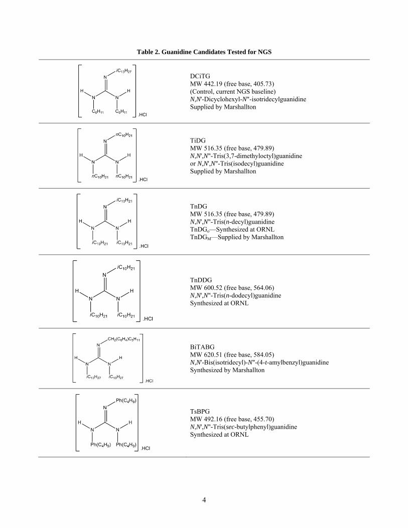
we examined five new guanidines in comparison to DCiTG used as a control. The guanidines tested are
shown in Table 2 in the form of their HCl salts. All of the new guanidines have higher molecular weights
than the control and are expected to have higher lipophilicity. Two of the candidates were designed to
have aromatic groups to aid detection by UV for high performance liquid chromatography (HPLC)
analysis. Three of the guanidines were symmetrical N,N’,N”-trialkylguanidines (i.e., the same alkyl group
is placed on each nitrogen), two with straight chains and one with branched chains. The symmetrical
structure would avoid scrambling of alkyl groups that we observed in the purification of DCiTG [14] as
well as offer some simplicity and lower cost in preparation. The three N,N’,N”-trialkylguanidines also
have a defined molecular weight (an advantage for mass-spectrometric analysis), though the branching in
TiDG, like that of DCiTG, gives a mixture of isomers that is somewhat inconvenient for chromatographic
analysis. An all-alkyl structure also leads to the expectation of stability comparable to DCiTG along with
equivalent extract/scrub/strip (ESS) behavior. At least for the N,N’,N”-trialkylguanidines, the technical
uncertainty in replacing DCiTG lies mostly in whether we might encounter unwanted changes in
interfacial or phase behavior, which can be sensitive to the structure of substituent alkyl groups. Test
solvents consisted of 0.050 M MaxCalix, 0.50 M Cs-7SB modifier, and 0.0030 M guanidine in Isopar L
diluent. Tests were designed to address the highest risks in replacing the guanidine and included
partitioning to the boric acid strip solution, ESS using simulated SRS salt waste and flowsheet solutions,
third-phase formation, emulsion formation, interfacial tension, and dispersion number (coalescence). It is
also possible to report here the partial results for a thermal-stability test for one-month exposure of the
TiDG solvent with SRS-15 simulant at 35 °C, the condition giving the most severe degradation in our
previous tests with DCiTG [16].
4
Table 2. Guanidine Candidates Tested for NGS
DCiTG MW 442.19 (free base, 405.73) (Control, current NGS baseline) N,N'-Dicyclohexyl-N"-isotridecylguanidine Supplied by Marshallton
TiDG MW 516.35 (free base, 479.89) N,N',N"-Tris(3,7-dimethyloctyl)guanidine or N,N',N"-Tris(isodecyl)guanidine Supplied by Marshallton
TnDG MW 516.35 (free base, 479.89) N,N',N"-Tris(n-decyl)guanidine TnDGo—Synthesized at ORNL TnDGM—Supplied by Marshallton
TnDDG MW 600.52 (free base, 564.06) N,N',N"-Tris(n-dodecyl)guanidine Synthesized at ORNL
BiTABG MW 620.51 (free base, 584.05) N,N'-Bis(isotridecyl)-N"-(4-t-amylbenzyl)guanidine Synthesized by Marshallton
TsBPG MW 492.16 (free base, 455.70) N,N',N"-Tris(sec-butylphenyl)guanidine Synthesized at ORNL

5
2. EXPERIMENTAL SECTION 2.1 MATERIALS
2.1.1 Solvent Components
Solvent components were obtained from commercial sources and judged to be of adequate purity for use
as received. 1-(2,2,3,3-Tetrafluoropropoxy),3-[4-(sec-butyl)phenoxy]-2-propanol (Cs-7SB modifier, Lot
No. MOD2010-M-[2] or MOD2012-M-1) and 1,3-alt-25,27-bis(3,7-dimethyloctyl-1-oxy)calix[4]arene-
benzocrown-6 (MaxCalix, Lot No. 71-061-15 or 79-239-1) were obtained from Marshallton Research,
and Isopar L (Lot No. US67377A) was obtained from ExxonMobil. MaxCalix Lot No. 71-061-15 and Cs-
7SB Lot No. MOD2010-M-[2] were used for all experiments other than the interfacial-tension
measurements. The suppressor candidates (see section 2.1.2) were used in the form of the HCl salts.
Solvents were prepared by weighing appropriate amounts of extractant, modifier, and suppressor into
volumetric flasks and diluting with Isopar L to the mark. Solutions were made assuming 100% purity.
The major components are shown in Table 1.
2.1.2 Guanidine Suppressors
The guanidine suppressor candidates obtained from Marshallton were DCiTG (Lot. No. 79-042-2), TiDG
(Lot. No. 79-175-1), TnDGm (Lot. No. 79-221-1), and BiTABG (Lot. No. 79-182-1). Each candidate was
used as received [>95% purity, verified by gas chromatography (GC) and electrospray mass spectrometry
upon receipt], without further purification. The TiDG (in CDCl3) was additionally checked by 1H and 13C
NMR on a Varian VNMRS 500 NMR spectrometer, and found to be ≥99% pure.
Previously published procedures [17,18,19], and modifications thereof, were followed in the synthesis of the
remaining guanidines (see below). All reagents employed in the preparations were used as received from
the suppliers without further purification unless otherwise noted. GC analyses were performed using a
Hewlett Packard HP6850 Series GC System, fitted with a Agilent J&W no. 122-1111E 15m x 0.250mm x
0.10μm narrow bore column with A DB-1HT stationary phase and using hydrogen as the carrier gas.
Analyses were performed at 200–350 °C at 25 °C/min with a 5-min hold period. Proton and carbon NMR
spectra were obtained in CDCl3 using a Bruker Avance III 400 MHz spectrometer, unless otherwise
noted. Chemical shifts were referenced to TMS at 0 ppm for proton, and CDCl3 at 77.23 ppm for carbon.

6
2.1.2.1 Generic preparation of N,N',N"-trialkylguanidine
The generic synthetic method that was followed in the creation of these guanidine suppressors follows:
Dialkylthiourea. Two equivalents of amine are dissolved in dry methylene chloride in a septum-sealed
flask and cooled in an ice water bath under an inert atmosphere. While stirring, thiosphosgene is slowly
added by syringe and the reaction allowed warm to room temperature overnight. If the thiourea does not
precipitate, it is isolated in vacuo and triturated with ether. Otherwise, the product is isolated by filtration
and washed with diethylether.
S-Methylthiouronium iodide. The purified di-alkylthiourea is dissolved in anhydrous THF (5 g in 75
mL) under a nitrogen atmosphere to a septum-sealed flask stirred in a room-temperature water bath while
excess methyl iodide (10 eq) is added by syringe. The reaction is allowed to proceed overnight, with
stirring, and yields a yellow or orange-colored crude product.
N, N’,N”-Trialkylguanidine. The crude reaction mixture from the thiouronium preparation is reduced in
vacuo, and 5 g is then redissolved in about 50 mL of anhydrous methanol, ethanol, or chloroform with 1
eq of amine. It is important to use dry solvents in all steps to avoid low yields and side products. The
reaction is refluxed until completion (indicated by GC), usually 24-48 h for alcohol solvent, or 3-4 days
for chloroform. The solvent is then removed in vacuo, re-dissolved in CHCl3, and washed three times
with equal volumes of 3 M NaOH, followed twice with 1 M NaOH, and finally three times with 1 M HCl.

7
The organic phase is washed with saturated NaCl, dried over MgSO4, and reduced to dryness in vacuo to
yield the trialkylguanidine hydrochloride salt. Product yields should be on the order of >95% without
further purification. Excess amine should be removed by Kugelrohr distillation.
2.1.2.2 N,N',N"-Tri-n-dodecylguanidine (TnDDG)
N,N’-Di-n-dodecylthiourea. n-Dodecylamine (5.0 g 27.0 mmol, 2 eq) was dissolved, with stirring, in
methylene chloride (ca. 100 mL) under a dry nitrogen gas purge in an ice-water bath. Thiophosgene (1.03
mL, 13.5 mmol, 1 eq) was added and the reaction allowed to come to room temperature and stirred for 12
hours. The thiourea was isolated by filtration and washed with diethyl ether (85–95%).
N,N’-Di-n-dodecyl-S-methylthiouronium iodide. N,N’-Di-n-dodecylthiourea (5.0 g, 12.1 mmol, 1 eq)
was placed in a septum-sealed flask under nitrogen purge. Anhydrous THF was added and the mixture
stirred and cooled using a room-temperature water bath. Excess methyl iodide (7.50 mL, 121 mmol, 10
eq) was added by syringe and the mixture stirred at room temperature overnight. (Caution: methyl iodide
is toxic and a suspected carcinogen; handle appropriately.) The solvent was removed in vacuo and the
crude product used without further purification.
N,N',N"-Tri-n-dodecylguanidine. The crude N,N’-di-n-dodecyl-S-methylthiouronium iodide was
dissolved in anhydrous EtOH, (50 mL) to which n-dodecylamine amine (2.24 g, 12.1 mmol, 1 eq) was
added. The reaction was refluxed for 48 h. The solvent was then removed in vacuo and the product re-
dissolved in CHCl3 followed by washing three times with equal volumes of 3 M NaOH, twice with 1 M
NaOH, and finally 3 times with 1 M HCl. The organic phase was washed with saturated NaCl, dried over
MgSO4, and the solvent removed in vacuo to yield the trialkylguanidine hydrochloride salt (80%). The
compound contains what is believed to be N,N’-di-n-dodecylurea at about 58 mol%, putting the purity of
the TnDDG at ca. 42 mol%. 1H NMR (Varian VNMRS 500; CDCl3, peaks listed with the same chemical
shift have a separation of <0.05 ppm): δ 6.88 (br t, 3H, -CNHCH2-), 3.29 (m, 6H, -NHCH2CH2-), 1.59 (p,
6H, -NHCH2CH2-), 1.38-1.18 (br m, overlaps with dodecylurea methylenes, 54H, -CH2(CH2)9CH3), 0.84
(t, overlaps with dodecylurea methyls, 9H, -CH3); 13C NMR (CDCl3): δ 155.7 (C-(NH-)3), 42.8
(-NHCH2CH2-), 32.1 (-NHCH2CH2-), 29.9, 29.8, 29.8, 29.7, 29.5, 29.5, 29.3, 27.0, 22.8 (-CH2- at chain
positions 3-11) , 14.3 (-CH3).
2.1.2.3 N,N',N"-Tri-n-decylguanidine (TnDGo)
1,3-Di-n-decylthiourea. n-Decylamine (5.0 g, 31.7 mmol, 2 eq) was dissolved with stirring in methylene
chloride (ca. 100 mL) under a dry nitrogen gas purge in an ice-water bath. Thiophosgene (1.20 mL, 15.9

8
mmol, 1 eq) was added and the reaction stirred overnight. The thiourea was isolated by filtration and
washed with diethyl ether (90–100%).
N,N'-Di-n-decyl-S-methylthiouronium iodide. 1,3-Di-n-decylthiourea (5.0g, 14.0 mmol, 1 eq) was
added to a nitrogen-purged septum-sealed flask. Anhydrous THF was added and the mixture stirred and
cooled in a room-temperature water bath. Excess methyl iodide (8.70 mL, 140 mmol, 10 eq) was added
by syringe and the reaction stirred at room temperature overnight. The solvent was removed in vacuo and
the crude product used without further purification.
N,N',N"-Tri-n-decylguanidine. The crude N,N'-di-n-decyl-S-methylthiouronium iodide was redissolved
in anhydrous CHCl3 (50 mL), and n-decylamine amine (2.20 g, 14.0 mmol, 1 eq) was added. The reaction
was refluxed for ca. 72 h. The solvent was removed in vacuo, and the product was redissolved in CHCl3
and washed 3 times with equal volumes of 3 M NaOH, followed twice with 1 M NaOH and finally three
times with 1 M HCl. The organic phase was washed with saturated NaCl and dried over MgSO4. The
solvent was removed in vacuo to yield the trialkylguanidine hydrochloride salt (75–80%). The purity is
estimated at 80–85%, based on NMR. 1H NMR (CDCl3): δ 8.23 (s, 3H, -CNHCH2-), 3.35 (q, 6H,
-NHCH2CH2-), 1.75 (m, 6H, -NHCH2CH2-), 1.27–1.19 (br m, 42H, -CH2(CH2)7CH3), 0.86 (t, 9H, -CH3); 13C NMR (CDCl3, peaks listed with the same chemical shift have a separation of <0.05 ppm): δ 154.6 (C-
(NH-)3), 42.8 (-NHCH2CH2-), 32.0 (-NHCH2CH2-), 29.8, 29.8, 29.5, 29.5, 29.3, 26.9, 22.8 (-CH2- at
chain positions 3-9) 14.2 (-CH3). 13C chemical shift assignments were made by comparing the spectrum
of this sample with the spectrum of a highly pure sample prepared by Marshallton.
2.1.2.4 N,N',N"-Tris(4-sec-butylphenyl)guanidine (TsBPG)
N,N'-Bis(1-sec-butylphenyl)thiourea. 4-sec-Butylaniline (5.0 g 33.5 mmol, 2 eq) was dissolved with
stirring in methylene chloride (ca. 100 mL) under a dry nitrogen gas purge in an ice-water bath.
Thiophosgene (1.26 mL, 16.75 mmol, 1 eq) was added and the mixture permitted to stir overnight. The
thiourea was isolated by filtration and washed with diethyl ether (95%).
N,N'-Bis(1-sec-butylphenyl)-S-methylthiouronium iodide. N,N'-Bis(1-sec-butylphenyl)thiourea (5.0
g, 14.6 mmol, 1 eq) was added to a nitrogen-purged flask to which anhydrous THF was added. The
mixture was stirred and cooled using a room-temperature water bath. Excess methyl iodide (9.0 mL, 146
mmol, 10 eq) was added by syringe and the reaction stirred at room temperature overnight. The solvent
was removed in vacuo and the crude product used without further purification.
N,N',N"-Tris(4-sec-butylphenyl)guanidine. The crude N,N'-bis(1-sec-butylphenyl)-S-methyl-
thiouronium iodide was redissolved in 50 mL anhydrous MeOH, and 4-sec-butylaniline (2.17g, 14.6
mmol, 1 eq) was added. The mixture was refluxed for 48 h, the solvent removed in vacuo, and the crude

9
product redissolved in CHCl3. The solution was washed three times with equal volumes of 3 M NaOH,
twice with 1 M NaOH, and finally three times with 1 M HCl. The organic phase was washed with
saturated NaCl and dried over MgSO4. Removal of the solvent in vacuo yielded the guanidine
hydrochloride salt (75%). 1H NMR (CDCl3): δ 6.98 (d, 6H, ArH2,6), 6.93 (d, 6H, ArH3,5), 2.43 (m, 3H,
-ArCHCH3), 1.44 (m, 6H, -CHCH2CH3), 1.08 (d, 9H, -CHCH3), 0.69 (t, 9H, -CH2CH3); 13C NMR (Varian
VNMRs 500; CDCl3): δ 153.2 (C-(NH-)3), 146.8 (Ar4), 132.4 (Ar1), 128.0 (Ar3.5), 124.2 (Ar2,6), 41.2
(-CHCH2CH3), 31.1 (-CHCH2CH3), 22.0 (-CHCH3), 12.2 (-CH2CH3). There appear to be two unidentified
compounds containing the 4-sec-butylphenyl group present in the sample, as visualized by NMR. The
major one could be 1,3-bis(4-sec-butylphenyl)urea, and the minor one could be 4-sec-butylaniline. For
these compounds, the mole ratio of TsBPG to 1,3-bis(4-sec-butylphenyl)urea to 4-sec-butylaniline
appears to be about 4:2:1, indicating a TsBPG mole% purity of approximately 57%.
2.1.3 Waste Simulants and Other Aqueous Solutions
The SRS-15 tank-waste simulant was prepared according to a method described previously [4,20]. It is
designed to represent the average SRS tank-waste composition [20] and is slightly modified to obtain the
SRS-SDS simulant [12] (see Table 3). Tracer 137Cs was added to the simulants for ESS tests (4 μL spike
from a 0.05 mCi/mL stock, CsCl in H2O, Eckert & Ziegler Isotope Products Inc., formally Isotope
Products, Burbank, CA).
Table 3. Aqueous Tank-Waste Simulants with Abbreviated Names Indicated
Simulant Simulant description
SRS-15 Average SRS salt waste simulant [9,19]
SRS-SDS SRS-15 with sodium dodecyl sulfate added to 5 × 10⁻⁴ M
Scrub solution (0.025 M NaOH) and other NaOH solutions were prepared by dilution of 1.0 M NaOH
standard solution (Sigma Aldrich). Strip solution (0.010 M H3BO3) was made by dilution of a 0.1 M
H3BO3 stock solution prepared from lab-grade H3BO3 (>95.5%, Sigma Aldrich). Solutions of HCl were
made from 1.0 M HCl standard solution (Baker). Water for preparation of all aqueous solutions was first
distilled and then deionized using a Milli-Q® gradient A10 filtering system equipped with a Quantum™
Ex Ultrapure Organex Cartridge (18.2 MΩ•cm at 25 °C, total organic content 4 ppb).

10
2.2 METHODS
The solvents used in the following studies were comprised of 0.050 M MaxCalix, 0.50 M Cs-7SB
modifier, and 0.0030 M suppressor in Isopar L. The solvent was prepared as described in section 2.1.1
and prewashed prior to use in the following manner: sequential contacts [single contact with an organic-
to-aqueous (O:A) phase ratio of 1:1] with 0.010 M HCl, H2O, then decreasing concentrations of NaOH
(0.3 M, 0.1 M, 0.03 M, and 0.01 M), and then with H2O until the solution was pH neutral. It was noted
that the organic phase was cloudy for TnDG and TnDDG on contacting the solvent with water following
the wash step with 0.010 M HCl.
2.2.1 Cesium Distribution Ratios in ESS Tests
Cesium distribution ratios in ESS tests were determined in a manner similar to that described previously [1,12], with one extraction stage followed by two scrub stages using 0.025 M NaOH and three strip stages
with 0.010 M H3BO3. The sequence, abbreviated as ES2S3, was run in duplicate for each set of conditions.
The organic and aqueous phases were contacted in polypropylene tubes (50 mL for extraction and
subsequently 15 mL for the scrubbing and stripping stages) sealed with Teflon tape to avoid organic loss
via leakage, mounted by clips on a disk rotated at ca. 60 rpm for 60 min for extractions and 45 min for
scrubs and strips. The solutions were contacted inside an air-box maintained at a temperature of 25.0 ±
0.5 °C. After the contacting period, the tubes were centrifuged for 5 min at 3000 rpm at 25.0 ± 0.5 °C. An
appropriate aliquot of each phase was subsampled and counted for 5 min using a Packard Cobra II Auto-
Gamma counter. A spike of 137Cs (0.05 mCi/mL stock, CsCl in H2O, Eckert & Ziegler Isotope Products
Inc., formally Isotope Products, Burbank, CA) was added to the second and third aqueous strip solutions,
owing to the low number of counts remaining after the each strip. To keep samples at the equilibration
temperature, tubes were removed individually from the temperature-controlled centrifuge for
subsampling. Cesium distribution ratios (DCs) are calculated as the ratio of organic- to aqueous-phase 137Cs activity.
Based upon the agreement of duplicate samples run within the same set of measurements, the precision of
DCs values within an ESS experiment run as described has generally been found [1] to worsen in the steps
of the sequence as follows: ±5% (extraction and scrubs), ±10% (first strip), and ±30% (second and third
strips). This duplicate precision correlates with volumetric precision (±3%) and counting precision, which
is approximately ±3% (extraction), ±1% (scrubs), ±10% (first strip), and ±30–50% (second and third
strips). Owing to the temperature sensitivity of cesium distribution (on the order of 10% change in DCs per
°C [1]), sample handling can introduce additional error. Thus, effective overall precision of extraction,

11
scrub, and first strip DCs values is estimated to be on the order of ±10%. Each value presented in the tables
in this report is the average of DCs values from duplicate ESS runs; the error given represents the standard
deviation of the duplicates, the parenthetic number referring to the precision of the corresponding
previous digit or, in a few cases, two digits [e.g., 2.11(3) × 10-1 means 0.211 ± 0.003 and 3.5(15) × 10-4
means 0.00035 ± 0.00015].
2.2.2 Partitioning of Suppressors into 10 mM Boric Acid
NG-CSSX solvent samples were precontacted with SRS-15 at an O:A phase ratio of 1:4, then
subsequently twice with 0.025 M NaOH at an O:A ratio of 3.75:1. The partitioning experiments were
carried out by contacting the preconditioned solvent with 0.010 M boric acid at O:A ratios of 1:10, 1:25,
1:50, and 1:100 in 50 mL polypropylene tubes sealed with Teflon tape to avoid organic loss via leakage,
mounted by clips on a disk, and rotated at ca. 60 rpm for 60 min. The solutions were contacted inside an
air-box maintained at a temperature of 25.0 ± 0.5 °C. After the contacting period, the tubes were
centrifuged for 5 min at 3000 rpm at 25.0 ± 0.5 °C (Beckman Coulter refrigerated centrifuge). The
organic layers were removed using Eppendorf micropipettes and briefly contacted with an equal volume
of 0.1 M NaOH to ensure the guanidine suppressor was in its neutral form. The solvents were then
separated again by centrifugation.
Chlorine-36 tracer was used to determine the concentration of the suppressors in the NG-CSSX solvents
before and after the contacting with boric acid and 0.1 M NaOH described in the preceding paragraph.
The solvent samples (300 µL) were contacted with HCl (270 µL, 0.01 M, diluted from a 0.1 M
standardized HCl stock solution) in 2.1 mL flip-top vials, spiked with 30 µL of 0.01 mCi 36Cl radiotracer
and placed on a wheel and contacted on a Glas-col laboratory disk rotator in a custom-made air box (60
rpm, 25.0 ± 0.5 °C) for 60 min. The samples were subsequently centrifuged for 5 min at 3000 rpm as
above, ensuring complete phase separation. Aliquots of 150 µL of each phase were pipetted into
scintillation vials containing 5 mL of scintillation cocktail. The chloride distribution ratios were
determined as the ratio of organic-to-aqueous phase 36Cl activity, employing standard liquid scintillation
counting. The chloride partition ratios DCl give the organic-phase chloride concentration through the
relation
Cl = DClCCl
φDCl +1 (1)
where CCl is the initial aqueous chloride concentration (set by the standard 0.01 M HCl), φ is the O:A
phase ratio, and the overbar indicates an organic-phase species. The guanidine partition ratio PGua is

12
figured by equating the organic-phase chloride concentration to the organic-phase guanidine
concentration before (pre) and after (post) contact with boric acid, as given in the following relation:
PGua =Gua Gua[ ]
=Cl post
Cl pre− Cl post( )φ
(2)
This method assumes that the chloride extracted by the solvent is completely due to the extraction of HCl
by the guanidine. The validity of this assumption was confirmed by repeating the procedure with a control
solvent sample having the NG-CSSX composition but without a guanidine. The organic-phase
concentration of chloride in the control was found to be 1.6 × 10⁻⁶ M.
Assuming that the contacting and counting procedure yields a value of DCl good to ±5%, the limit of
quantitation of this method was assumed to correspond to a depletion of the organic-phase guanidine
concentration of ≥10%. From Eq. 2, we have PGua,lim = 10/φ. Thus, at an O:A ratio of 1:100 (φ = 0.01), we
can measure a guanidine partition ratio up to 1000. However, a propagation-of-error analysis based on
Eqs. 1 and 2 shows that the value of PGua becomes increasingly uncertain as it approaches PGua,lim.
2.2.3 Third-Phase Formation
Third-phase tests were performed by contacting aliquots of prewashed NG-CSSX solvent (0.050 M
MaxCalix, 0.50 M Cs-7SB modifier, and 0.0030 M suppressor) containing 3 mM of each of following
suppressor candidates, DCiTG, TnDGo, TiDG, TnDDG, TsBPG, and BiTABG, with each of the aqueous
process solutions (SRS-15 simulant, 0.025 M NaOH, and 0.01 M H3BO3) in an ESS sequence at 10.0 ±
0.1 °C for 45 min. Thus, the solvents contacted with 0.025 M NaOH scrub solution were done so after
being precontacted with SRS-15 at an O:A ratio of 1:4. The solvents contacted with 0.01 M H3BO3 strip
solution were done so after being precontacted with SRS-15 at an O:A ratio of 1:4, then twice with NaOH
at an O:A ratio of 3.75:1. The tests were conducted on a Glas-col laboratory disk rotator in a Fisher
Scientific Low Temperature incubator using 2 mL Eppendorf flip-top polypropylene tubes containing an
equal volume (500 μL) of preconditioned solvent with each aqueous solution. A NIST traceable
thermometer was placed inside the incubator. Each of the samples was visually inspected by two
independent experimentalists for the presence of any third phase at the interface.
13
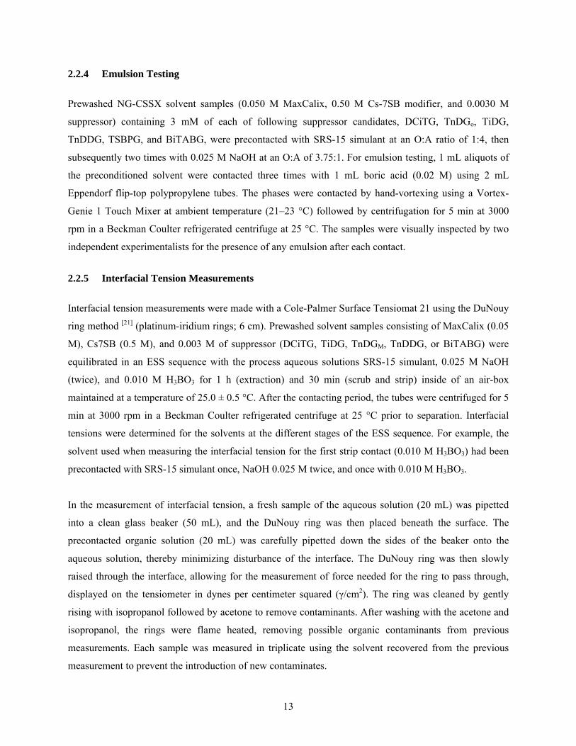
2.2.4 Emulsion Testing
Prewashed NG-CSSX solvent samples (0.050 M MaxCalix, 0.50 M Cs-7SB modifier, and 0.0030 M
suppressor) containing 3 mM of each of following suppressor candidates, DCiTG, TnDGo, TiDG,
TnDDG, TSBPG, and BiTABG, were precontacted with SRS-15 simulant at an O:A ratio of 1:4, then
subsequently two times with 0.025 M NaOH at an O:A of 3.75:1. For emulsion testing, 1 mL aliquots of
the preconditioned solvent were contacted three times with 1 mL boric acid (0.02 M) using 2 mL
Eppendorf flip-top polypropylene tubes. The phases were contacted by hand-vortexing using a Vortex-
Genie 1 Touch Mixer at ambient temperature (21–23 °C) followed by centrifugation for 5 min at 3000
rpm in a Beckman Coulter refrigerated centrifuge at 25 °C. The samples were visually inspected by two
independent experimentalists for the presence of any emulsion after each contact.
2.2.5 Interfacial Tension Measurements
Interfacial tension measurements were made with a Cole-Palmer Surface Tensiomat 21 using the DuNouy
ring method [21] (platinum-iridium rings; 6 cm). Prewashed solvent samples consisting of MaxCalix (0.05
M), Cs7SB (0.5 M), and 0.003 M of suppressor (DCiTG, TiDG, TnDGM, TnDDG, or BiTABG) were
equilibrated in an ESS sequence with the process aqueous solutions SRS-15 simulant, 0.025 M NaOH
(twice), and 0.010 M H3BO3 for 1 h (extraction) and 30 min (scrub and strip) inside of an air-box
maintained at a temperature of 25.0 ± 0.5 °C. After the contacting period, the tubes were centrifuged for 5
min at 3000 rpm in a Beckman Coulter refrigerated centrifuge at 25 °C prior to separation. Interfacial
tensions were determined for the solvents at the different stages of the ESS sequence. For example, the
solvent used when measuring the interfacial tension for the first strip contact (0.010 M H3BO3) had been
precontacted with SRS-15 simulant once, NaOH 0.025 M twice, and once with 0.010 M H3BO3.
In the measurement of interfacial tension, a fresh sample of the aqueous solution (20 mL) was pipetted
into a clean glass beaker (50 mL), and the DuNouy ring was then placed beneath the surface. The
precontacted organic solution (20 mL) was carefully pipetted down the sides of the beaker onto the
aqueous solution, thereby minimizing disturbance of the interface. The DuNouy ring was then slowly
raised through the interface, allowing for the measurement of force needed for the ring to pass through,
displayed on the tensiometer in dynes per centimeter squared (γ/cm2). The ring was cleaned by gently
rising with isopropanol followed by acetone to remove contaminants. After washing with the acetone and
isopropanol, the rings were flame heated, removing possible organic contaminants from previous
measurements. Each sample was measured in triplicate using the solvent recovered from the previous
measurement to prevent the introduction of new contaminates.

14
2.2.6 Dispersion Number Testing
The dispersion number, a dimensionless quantity that describes the tendency of a dispersion of two
immiscible liquids to separate into its component phases [22], was determined for the NG-CSSX solvent
compositions containing selected guanidines at each point of an ESS sequence (Eq. 3). The dispersion
number NDi is determined by agitating the bulk solutions so as to generate a dispersion and measuring the
break time tb, the time required for the two phases to coalesce, leaving a clear interface. In Eq. 3, the
dispersion number is calculated from the thickness of the dispersion band reduced by a height z at an
acceleration of a. In the work reported, predetermined volumes of aqueous and organic solutions were
placed into a 100 mL graduated cylinder, a ground glass stopper was placed into the cylinder, and the
solutions were agitated to create the dispersion. In the extraction protocol, the ratio of solvent to SRS-15
simulant was 1:4. Due to the limited amount of simulant available, two extractions were performed on 48
mL of SRS-15 using 12 mL of the specified solvent each time. The two solvent lots were then combined
for the subsequent scrubbing and stripping procedures. The O:A ratio in the scrub step was 3.75:1 and
involved 6.4 mL of 0.025 M NaOH and 24 mL of solvent. Likewise, the four stripping steps were
performed at and O:A ratio of 3.75:1 and involved 6.4 mL of 0.010 M HBO3 and 24 mL of solvent.
Agitation was performed manually; the cylinder was vigorously shaken vertically for 20 s, allowed to
stabilize for 10 s, and agitated for another 20 s interval, after which timing was initiated. In all cases, the
method of agitation resulted in the entire depth of liquid becoming dispersed, and separation was timed
until the interface between the two liquids returned to its original position and no individually
distinguishable droplets were visible in either phase. The next determination was continued after complete
transparency of both bulk phases was restored. Using the procedure described, z becomes the total height
of the liquid column in the graduated cylinder and a is the gravitational constant. Where NDi values were
obtained under extraction, scrubbing, stripping, and washing conditions, the determinations were made
sequentially, and the solvent was retained and reused in sequence in order to simulate solvent use in a full
mass-transfer cascade.
NDi = 1
tb
za
(3)
As indicated by the expression, the dispersion number is inversely proportional to the time required for a
band of dispersed liquids to separate into its component solutions; hence, higher values of NDi indicate
greater ease of separation.

15
2.2.7 Thermal Stability Test NG-CSSX solvent obtained from ORNL, consisting of 0.050 M MaxCalix, 0.50 M Cs-7SB modifier, and
0.0030 M TiDG, was thermally treated at Tennessee Technological University by sustained contact with
SRS-15 simulant. The samples were contained in sealed Teflon-FEP tubes, using Teflon (pipe thread)
tape to avoid significant solvent loss over time. The initial masses of the sealed samples were taken, and
any sample loss was determined via mass difference. It was assumed that any mass loss was due to the
evaporation of Isopar L. Before testing, the samples were returned to their original mass by the addition
of Isopar L. Altogether, 10 aliquots of NG-CSSX solvent, 8 mL each, were put into contact with SRS-15
simulant at an O:A ratio of 1:4 in separate tubes. An initial duplicate ESS run was completed immediately
on two of the tubes to provide a baseline for freshly prepared, untreated NG-CSSX solvent (“0 month”
samples). Four tubes were subjected to thermal treatment in a Lab Line Orbit Environ Shaker, Lab Line
Instrument Inc, held at a constant temperature of 36.0 ± 0.5 °C and 250 rpm; two of these were withdrawn
after 30 days (“1 month”) and subjected to ESS analysis as described below; thermal treatment was
continued for the other two tubes to be withdrawn and analyzed at a later time (not reported here). Four
other tubes were stored in a refrigerator at 3 °C (not analyzed in this report). Solvent samples not
contacted with SRS-15 simulant were set aside as follows: (a) in a refrigerator at 3 °C; (b) in an incubator
held at 36.0 ± 0.5 °C; and (c) at room temperature. A portion of the solvent held at room temperature was
withdrawn for ESS testing as the “1 month” sample for comparison with the sample thermally treated for
one month.
Cesium distribution ratios were determined in duplicate ES2S3 tests with simulants spiked with 137Cs in a
manner similar to that described previously [1,12]. Extraction steps consisted of NG-CSSX solvent being
contacted with SRS-15 simulant waste with an O:A ratio of 1:4. The scrub steps consisted of the solvent
being contacted with 25 mM NaOH with an O:A ratio of 3.75:1. The strip steps consisted of the solvent
being contacted with 10 mM H3BO3 with an O:A ratio of 3.71:1. Unlike previously reported methods,
here a final extraction contact was performed following the previous ES2S3 sequence (to give an ES2S3E
sequence). For determination of the cesium distribution ratios, the organic and aqueous phases were
contacted in Teflon-FEP centrifuge tubes (50 mL). These solutions were contacted on an orbital shaker
and equilibrated at a temperature of 25.0 ± 0.5 °C in a constant-temperature water bath (ThermoScientific
Refrigerated/Heater Bath Circulator). After the contacting period, the tubes were centrifuged for 10 min at
3000 rpm (at ambient temperature) and returned to the constant temperature bath for at least 10 min to re-
equilibrate to 25 °C. An appropriate aliquot of each phase was subsampled and counted using a Packard
Cobra II Auto-Gamma counter. A spike of 137Cs was added (4 μL of a 0.05 mCi/mL stock, CsCl in H2O)

16
to the second and third aqueous strip solutions, owing to the low number of counts remaining after the
each strip and then respiked for the final extraction stage.

17
3. RESULTS AND DISCUSSION
3.1 ESS TESTING OF SUPPRESSOR CANDIDATES
Standard ESS tests (see Table 4) showed that five guanidines, including DCiTG as a control, performed
equivalently. Performance was also adequate when stressed with SDS (Table 6). The aromatic guanidine
TsBPG failed to strip properly, likely owing to insufficient basicity. Tests were carried out under standard
conditions at 25 °C with SRS-15 simulant (O:A = 4:1), 0.025 M NaOH scrub solution (O:A = 3.75:1),
and 0.010 M boric acid strip solution (O:A = 3.75:1).
With the exception of TsBPG, the structure of the guanidine does not have an appreciable effect on the
ability of the solvent to function properly in ESS tests starting with either SRS-15 or SRS-SDS (SRS-15
with added sodium dodecyl sulfate) simulants. Under the alkaline conditions of extraction and scrubbing,
no effect was expected in either case, as the guanidines are expected to be in their neutral form. Under
conditions of stripping, the test revealed TsBPG to perform poorly, eliminating it from further
consideration. Because of the electron-withdrawing effect of the phenyl groups attached to the nitrogen
atoms, the basicity of this guanidine is expected to be significantly reduced, thereby compromising its
effectiveness as a suppressor.
Table 6 below shows a small effect of the surfactant SDS, confirming the effectiveness of the suppressing
action of all guanidine candidates except TsBPG. Surfactant was earlier identified as a potential
interferent in CSSX, and the mechanism of the role of TOA has been discussed [3,4]. In brief, the
surfactant anion is more lipophilic than other anions in the system and thereby acts to make cesium more
extractable, resisting stripping. The guanidine is expected to suppress the effect of surfactants in the same
manner as TOA [12], essentially by extracting the surfactant anion and a proton from the strip solution,
thereby eliminating the surfactant from the cesium stripping equilibrium. The guanidine should release
the surfactant in the wash and extraction sections of the flowsheet. A small increase in DCs can be
detected in scrubbing (Table 6). The surfactant consistently raises DCs on stripping, but the effect is slight,
and the scatter in the DCs values is increased.

18
Table 4. Cesium Distribution Ratios for ESS Batch Tests for Each of the Suppressor Candidatesa
Stage DCiTG (Mar)
DCiTGb (Mar)
TiDG (Mar)
TiDGb (Mar)
TnDGo (ORNL)
TnDGMb
(Mar) TsBPG (ORNL)
TnDDG (ORNL)
BiTABG (Mar) Averagec
Extract 63(2) 55.2(3) 61(1) 52.9(2) 61.8(8) 56.4(14) 65(2) 59.0(8) 60(3) 59(4)
Scrub 1 2.9(2) 2.7(2) 2.9(3) 2.41(2) 3.1(4) 2.2(6) 3.3(2) 2.9(4) 3.0(3) 2.8(3)
Scrub 2 1.2(1) 2.05(5) 1.09(9) 0.84(2) 1.30(9) 0.80(6) 1.5(1) 1.26(6) 1.2(1) 1.2(4)
Strip 1 2.81(8) × 10-3 1.6(1) × 10-3 1.7(1) × 10-3 1.1(2) × 10-3 2.7(3) × 10-3 1.03(2) × 10-3 2.8(2) × 10-1 2.6(4) × 10-3 3.1(3) × 10-3 2.1(8) × 10-3
Strip 2 3.2(6) × 10-4 3.7(2) × 10-4 1.24(7) × 10-4 2(1) × 10-4 2.6(2) × 10-4 1.07(2) × 10-4 3.4(2) × 10-1 3(1) × 10-4 1.8(7) × 10-4 2.3(9) × 10-4
Strip 3 1.5(2) × 10-4 2.7(7) × 10-4 1.19(5) × 10-4 1.1(9) × 10-4 1.44(9) × 10-4 3(2) × 10-5 3.5(2) × 10-1 1.4(1) × 10-4 1.6(6) × 10-4 1.4(6) × 10-4 aThe aqueous phases were SRS-15 waste simulant (composition defined in Table 3) for extraction, 0.025 M sodium hydroxide for scrubs, and 0.01 M boric acid for strips. Solvent compositions consisted of 0.050 M MaxCalix, 0.50 M Cs-7SB, and 0.0030 M guanidine as indicated, in Isopar L diluent. The O:A ratios were 1:4 for extraction and 3.75:1 for both scrubbing and stripping stages. The contact temperature was maintained at 25 ± 1 ºC. bESS testing was performed on a separate occasion, the DCiTG (Mar) suppressor being used as a control. The contact temperature was maintained at 25.0 ± 0.5 ºC. cAverage for all columns except that of TsBPG.
Table 5. Cesium Distribution Ratios for ESS Batch Tests for Each of the Suppressor Candidates Stressed by Addition of SDS to the Waste Simulanta
Stage DCiTG (Mar)
DCiTGb (Mar)
TiDG (Mar)
TiDGb (Mar)
TnDGo (ORNL)
TnDGMb
(Mar) TsBPG(ORNL)
TnDDG (ORNL)
BiTABG (Mar) Averagec
Extract 61(4) 60.8(6) 58.6(1) 57.5(6) 60(2) 56(1) 62.7(8) 59.4(7) 60.0(8) 59(2)
Scrub 1 3.7(1) 3.8(2) 3.9(2) 4(1) 4.6(1) 3.0(4) 4.2(1) 4.2(3) 4.1(1) 3.9(5)
Scrub 2 2.04(3) 1.9(2) 2.2(2) 1.6(1) 3.1(4) 1.1(1) 2.71(7) 2.7(8) 2.5(2) 2.1(6)
Strip 1 4.7(3) × 10-3 3.3(2) × 10-3 3.4(4) × 10-3 2.2(3) × 10-3 7.1(4) × 10-3 1.33(4) × 10-3 1.0(5) 8.3(2) × 10-3 6.8(3) × 10-3 5(3) × 10-3
Strip 2 3.9(8) × 10-4 5.7(9) × 10-4 1.83(1) × 10-4 2.16(1) × 10-4 4(1) × 10-4 6(6) × 10-5 1.2(4) 4.3(5) × 10-4 2.60(8) × 10-4 3(2) × 10-4
Strip 3 3.5(4) × 10-4 2.79(8) × 10-4 1.3(1) × 10-4 1.73(5) × 10-4 5.3(7) × 10-4 1.6(7) × 10-4 1.2(2) 4.76(9) × 10-4 2.1(1) × 10-4 3(2) × 10-4 aThe aqueous phases were SRS-SDS waste simulant (composition defined in Table 3) containing 0.01 M sodium dodecyl sulfate for extraction, 0.025 M sodium hydroxide for scrubs, and 0.01 M boric acid for strips. Solvents consisted of 0.050 M MaxCalix, 0.50 M Cs-7SB modifier, and 0.0030 M guanidine as indicated, in Isopar L diluent; source of guanidine is either ORNL or Marshallton (Mar). The O:A ratios were 1:4 for extraction and 3.75:1 for both scrubbing and stripping stages. The contact temperature was maintained at 25 ± 1 ºC. bESS testing was performed on a separate occasion, the DCiTG (Mar) suppressor being used as a control. The contact temperature was maintained at 25.0 ± 0.5 ºC. cAverage for all columns except that of TsBPG.

19
3.2 PARTITIONING OF SUPPRESSOR INTO BORIC ACID
All guanidine candidates (except for TsBPG, which wasn’t tested) were found to have higher partition
ratios PGua for NG-CSSX solvents in contact with boric acid strip solution than that of the DCiTG
control. The guanidine candidates all possess higher molecular weights due to their overall larger
hydrocarbon substituents as compared with DCiTG, and they are therefore expected to exhibit higher
lipophilicity. The worst loss of guanidine in the flowsheet is expected to occur in the strip section, where
the guanidine can become protonated, becoming somewhat aqueous soluble. The low value of PGua for
DCiTG under these conditions was unexpected and is thought to be related to the inability of borate to be
extracted by the guanidine, drawing the protonated guanidine into the aqueous phase [12]. As shown in
Table 6, all of the guanidine candidates proved to be superior to DCiTG with regards to lipophilicity.
The method used to determine PGua was an indirect extraction of HCl traced with chlorine-36, which by
the difference in extraction of HCl before and after a partition contact of the solvent with boric acid at a
low O:A ratio down to 1:100 gives PGua (see Experimental Section). The limit of quantitation was
estimated to be PGua < 1000. As may be seen in Table 6, TiDG and BiTABG both exceeded this limit.
Interestingly, TnDDG gave a lower PGua value than the smaller-chain analog TnDG, which remains
unexplained. It may have to do with aqueous micellation or other interfacial behavior not seen with the
branched-chain guanidines TiDG and BiTABG. However, the behavior could also be due to the low
purity of the samples of TnDGo and TnDDG that were used (see Experimental Section).
Table 6. Guanidine Partition Ratios for NG-CSSX Solvent in Contact with 10 mM Boric Acid Strip Solution at 25 °C
Guanidine PGua DCiTG 30.2 ± 1.5 TiDG >1000 TnDGo 480 ± 250 TnDDG 100 ± 11 BiTABG >1000
3.3 THIRD-PHASE TEST RESULTS
Visual tests of the six solvents in contact with SRS-15, scrub solution, and strip solution at 10 °C did not
indicate any evidence for third-phase formation under potential process conditions (Table 7). Third-
phase formation occurs under certain loading conditions for almost all solvent-extraction systems. It
cannot be tolerated in engineering equipment, and thus, it is essential to confirm that there is no potential
for its occurrence under anticipated NG-CSSX processing conditions. Since the formation of third
phases in the CSSX solvent has been associated primarily with potassium extraction by the calixarene, it

20
was considered unlikely that the guanidine choice would play a role in third-phase formation in
extraction or scrubbing. The new boric acid stripping chemistry, however, necessitated a test to eliminate
potential risk, which was a simple visual check under ESS conditions. The test revealed no evidence for
third-phase formation under any process conditions.
Table 7. Third-Phase Test Results for Solvent Contacts with Boric Acid Strip Solutiona
Stage DCiTG TiDG TnDGo TsBPG TnDDG BiTABG Extract (SRS-15 simulant) N/O N/O N/O N/O N/O N/O Scrub (NaOH, 25 mM) N/O N/O N/O N/O N/O N/O Strip (H3BO3, 10 mM) N/O N/O N/O N/O N/O N/O aSolvents consisted of 0.050 M MaxCalix, 0.50 M Cs-7SB modifier, and 0.0030 M guanidine as indicated, in Isopar L diluent. The O:A ratios were 1:1 for all stages. The contact temperature was maintained at 10 ± 1 ºC. N/O = no third phase observed.
3.4 EMULSION TESTING
Emulsion tests for the solvents in contact three times with process solutions and three stripping contacts
with 0.020 M boric acid were also negative. Like third-phase formation, any tendency to form an
emulsion under process conditions presents a risk of process upset. Emulsions have been observed in
repeated stripping contacts using DCiTG solvent systems if the aqueous boric acid concentration is
raised to 0.1 M, especially if the guanidine concentration is raised higher than 10 mM [23]. Given the
unknown interfacial behavior of the different guanidines, it was deemed prudent to include a check for
emulsion formation in the present series of development tests. Since it is possible that a future flowsheet
modification could employ a higher boric acid concentration than the currently used 10 mM, the test
employed 20 mM boric acid, a more severe test than would be the case with 10 mM boric acid. As
shown in Table 8, no observation of emulsion formation was made in a series of ESS contacts at 25 °C.
Table 8. Emulsion Test Results for NGS Candidate Solvents in Contact with 20 mM Boric Acida
Stage DCiTG TiDG TnDGo TsBPG TnDDG BiTABG Contact 1 N/O N/O N/O N/O N/O N/O Contact 2 N/O N/O N/O N/O N/O N/O Contact 3 N/O N/O N/O N/O N/O N/O aSolvents consisted of 0.050 M MaxCalix, 0.50 M Cs-7SB modifier, and 0.0030 M guanidine as indicated, in Isopar L diluent. The O:A ratios were 1:1 for each contact. The contact temperature was maintained at 10 ± 1 ºC. N/O = no emulsion observed. 3.5 INTERFACIAL TENSION TEST RESULTS
A series of adapted ESS experiments revealed that the guanidine suppressors depress the interfacial
tension under stripping conditions and that the effect depends upon the guanidine structure. Low

21
interfacial tensions can serve as an indicator of potential coalescence or other interface-related problems.
Given that some conditions for emulsion formation had been identified, albeit at abnormal
concentrations of boric acid and guanidine (see above), guanidine interfacial activity was suspected.
Thus, an ESS experiment was devised for examination of the variation of interfacial tension of NG-
CSSX solvent as it is stepped through the ESS sequence for each of the different guanidine candidates.
As shown in Table 9, the guanidines have no detectable interfacial activity vs the control solvent without
guanidine under the alkaline conditions of extraction and scrubbing. However, the guanidines behave
differently under stripping conditions. The differences range from almost no effect (BiTABG), to
moderate decrease of interfacial tension (DCiTG and TiDG), to a large decrease in interfacial tension
(TnDGM and TnDDG). As a reference point [5], the CSSX solvent gave the following interfacial tensions
for extraction, scrubbing, and stripping conditions, respectively (dyne/cm): 18.8, 16.1, and 15.2. The
CSSX solvent tested contained only 1 mM TOA, and the aqueous strip solution was 1 mM nitric acid. It
appears that the straight-chain structure of TnDGM and TnDDG produces greater interfacial activity
under NG-CSSX conditions.
Table 9. Interfacial Tension of Candidate NG-CSSX Solvents Under ESS Conditionsa
Stage Control No Gua DCiTG TiDG TnDGM TnDDG BiTABG
Extract 18.0(4) 18.3(6) 18.2(3) 18.2(3) 19.0(4) 19(1)
Scrub 16.0(4) 15(1) 15(1) 16.8(3) 16.8(3) 17.7(6)
Strip 16.3(6) 10.8(8) 9.7(3) 6.0(4) 5.33(3) 15.2(3) aThe aqueous phases were SRS-15 waste simulant for extractions, 0.025 M NaOH for scrubs, and 0.01 M boric acid for strips. Solvents consisted of 0.050 M MaxCalix, 0.50 M Cs-7SB modifier, and 0.0030 M guanidine as indicated, in Isopar L diluent. The O:A ratios were 1:4 for extraction and 3.75:1 for both scrubbing and stripping stages. The precontact temperature was maintained at 25.0 ± 0.5 ºC. Interfacial tension measurements were performed at room temperature, measured at 24.5 ± 0.5 ºC. Units are dyne cm–1. The deviation of duplicate determinations is shown in parentheses, unless the duplicates agreed exactly, in which case the average deviation (±0.4 dyne cm–1) is given. 3.6 DISPERSION NUMBERS Dispersion numbers as a measure of coalescence rate indicated no particular differences among the four
guanidines tested, DCiTG, TiDGo, TnDDG, and BiTABG. While no simple test reliably predicts
contactor performance, the dispersion number derived from simple break times serves as a rough
indicator of behavior, allowing one to categorize performance as poor to excellent [21,23]. As such,
dispersion numbers serve as an operational indicator for making systematic comparisons [24]. Table 10
summarizes the results of an ESS style experiment in which the break times tB were measured for each
step for NG-CSSX solvent with the different guanidines. The dispersion number NDi was calculated
according to Eq. 3. All extraction contacts exhibited “very good” phase disengagement (NDi = 8–16 ×

22
10-4). All scrub contacts exhibited “good” phase disengagement (NDi = 4–8 × 10⁻⁴). The first two strip
contacts ranged from “good” to “very good,” while the third and fourth strips were “good.” Within the
variability of the results, it is judged that the guanidines do not exhibit noticeable differences in
coalescence behavior. Whatever differences exist among the guanidines with regard to interfacial
tension, particularly under stripping conditions, apparently are not reflected in differences in dispersion
number. This is somewhat surprising for TnDDG, whose interfacial tension under stripping conditions
was potentially problematic.

23
Table 10. Dispersion Numbers for Various Guanidine Suppressorsa
Stage DCiTG TiDG TnDDG BiTABG
Avg. tb, s NDi Avg. tb, s NDi Avg. tb, s NDi Avg. tb, s NDi
Extract 1 100(2) 1.08(2) × 10-3 110(2) 9.8(2) × 10-4 76(3) 1.42(6) × 10-3 95(3) 1.13(4) × 10-3
Extract 2 115(6) 9.4(5) × 10-4 84(2) 1.28(3) × 10-3 92(2) 1.17(3) × 10-3 110(2) 9.8(1) × 10-4
Scrub 1 167(13) 5.8(4) × 10-4 127(4) 7.6(2) × 10-4 119(10) 8.0(7) × 10-4 126(4) 7.6(2) × 10-4
Scrub 2 195(18) 5.0(5) × 10-4 160(13) 6.0(5) × 10-4 138(12) 7.1(6) × 10-4 144(5) 6.7(2) × 10-4
Strip 1 102(11) 9.5(10) × 10-4 107(12) 9(1) × 10-4 149(5) 6.5(2) × 10-4 91(3) 1.03(3) × 10-3
Strip 2 122(3) 8.0(2) × 10-4 137(5) 7.0(2) × 10-4 178(6) 5.4(2) × 10-4 149(3) 6.5(1) × 10-4
Strip 3 167(14) 5.8(5) × 10-4 172(8) 5.6(2) × 10-4 178(5) 5.4(2) × 10-4 144(4) 6.7(2) × 10-4
Strip 4 153(8) 6.4(3) × 10-4 167(1) 5.78(5) × 10-4 162(10) 5.9(4) × 10-4 149(1) 6.44(5) × 10-4 aThe aqueous phases were SRS-15 waste simulant for extraction, 0.025 M sodium hydroxide for scrubs, and 0.01 M boric acid for strips. Solvents consisted of 0.050 M MaxCalix, 0.50 M Cs-7SB modifier, and 0.0030 M guanidine as indicated, in Isopar L diluent. The O:A ratios were 1:4 for extraction and 3.75:1 for both scrubbing and stripping stages. Two extractions were carried out due to limited simulant (SRS-15) then the solvent phases were combined for the scrubbing and stripping stages.
24
3.6.1 Thermal Stability Test
We report here preliminary results of a test of the NG-CSSX solvent containing TiDG suppressor in
sustained contact with SRS-15 simulant at 36.0 ± 0.5 °C for one month. In previous work with
DCiTG[16], the alkaline conditions of extraction and scrubbing were found to be more severe than
stripping conditions using 10 mM boric acid with regard to deterioration of ESS performance. Given the
choice of TiDG as recommended suppressor for NGS in this work, it was judged prudent to confirm that
NGS solvent with TiDG has comparable thermal stability to solvent with DCiTG, considered to be in
contact with SRS-15. Owing to the temperature control used in the MCU, the maximum temperature
expected under alkaline conditions of extraction and scrubbing is expected to be 26 °C; the extraction
section in the MCU is held to 23 ± 3 °C, and the scrub section, which receives the cool solvent, is not
expected to exceed 26 °C [25]. Thus, the results of this test are considered to correspond to off-normal
conditions (beyond worst case).
The test results are shown in Table 11. The samples at 0 and 1 month represent the thermal test samples at
the initial and first sampling. The control corresponds to untreated solvent held at room temperature with
no aqueous phase present. While the 0 month and control samples appear normal in behavior, it may be
seen that the thermal TiDG sample exhibits a lower-than-normal DCs value for extraction and a higher-
than-normal DCs value on the first strip (see Table 4 for typical DCs values in ESS testing.) The extraction
DCs value returns to normal on the second extraction step. For comparison, the results for a comparable
thermal test of the analogous NG-CSSX solvent containing the DCiTG suppressor [16] are shown in Table
11. In that test, the ESS measurements were taken after the thermally treated solvent had been run through
the remainder of the first ESS sequence. It may be seen that thermally treated TiDG and DCiTG behave
similarly in scrubbing and stripping. Overall, while stripping performance degrades with thermal
treatment in both cases, the ESS behavior of solvents containing either suppressor remains excellent over
the course of a month of treatment.

25
Table 11. Cesium Distribution Ratios for ESS Batch Tests for Thermally Treated Solvents Containing TiDG and DCiTGa
Stage TiDG
0 Months
TiDG 1 Month Control
TiDG 1 Month Thermal
DCiTG [16] 0 Months
DCiTG [16] Month Control
DCiTG [16] 1 Month Thermal
Extract 1 58.5(7) 68.2(7) 35.9(7) 60.0(6)
Scrub 1 3.76(8) 3.22(4) 4.21(4) 2.8(2)
Scrub 2 1.18(7) 1.09(7) 1.26(7) 1.01(3)
Strip 1 2.00(4) × 10-3 1.53(4) × 10-3 1.14(5) × 10-2 1.3(1) × 10-3
Strip 2 3.71(3) × 10-4 2.87(3) × 10-4 4.07(4) × 10-3 2.1(8) × 10-4
Strip 3 1.87(6) × 10-2 4.23(3) × 10-4 4.88(2) × 10-3 1.5(2) × 10-4
Extract 2 57.3(7) 49.7(7) 50.2(7) 55(1) 74(5)
Scrub 1 2.7(4) 4.2(3)
Scrub 2 0.93(5) 1.89(5)
Strip 1 1.25(3) × 10-3 1.12(2) × 10-2
Strip 2 4.3(5) × 10-4 2.5(3) × 10-3
Strip 3 2(2) × 10-4 9(3) × 10-4 aThe aqueous phases were SRS-15 waste simulant for extraction, 0.025 M NaOH for the scrub stages, and 0.01 M H3BO3 for the strip stages. Solvents consisted of 0.050 M MaxCalix, 0.50 M Cs-7SB modifier, and 0.0030 M guanidine as indicated, in Isopar L diluent. The O:A ratios were 1:4 for extraction and 3.75:1 for both scrubbing and stripping. ESS measurements were carried out at a constant temperature of 25.0 ± 0.5 °C. Samples marked “0 Months” were run at the outset of the experiment, with no thermal treatment. Samples marked “Control” were from the original batch of solvent held at room temperature not in contact with an aqueous phase. Thermal samples were treated in contact with SRS-15 simulant at an O:A ratio of 1:4 at nominally 35 °C.


27
CONCLUSIONS
Two new guanidines, TiDG and BiTABG, tested as candidate suppressors for the NG-CSSX process
possess superior lipophilicity (PGua > 1000) over the control suppressor DCiTG (P = 30) and otherwise
perform well with regard to essential properties, including ESS, resistance to third-phase formation,
resistance to emulsion formation, interfacial tension, and coalescence (dispersion number). Assuming loss
to the strip solution is the major loss pathway for the guanidine suppressor, the concentration of both
TiDG and BiTABG would be expected to be reduced to half the initial value of 3 mM after more than
2600 solvent cycles, compared with 78 solvent cycles for DCiTG. The reduced loss rate translates to
reduced costs of solvent monitoring and reduced risk of process upset. An additional benefit of higher
guanidine lipophilicity is more than an order-of-magnitude lower organic concentration in the effluent
stream going to the downstream vitrification facility (Defense Waste Processing Facility). For DCiTG,
the partition ratio of 30 at an O:A ratio of 3.75:1 implies that the strip effluent will contain 40 ppm of
guanidine, as compared with <1.4 ppm for TiDG or <1.7 ppm for BiTABG.
Minor considerations lead to TiDG as the preferred choice vs BiTABG. First, in having all alkyl
substituents, TiDG is chemically more similar to the reference guanidine DCiTG than is the aromatic
BiTABG. In particular, the benzylic hydrogens (the hydrogen atoms of the CH2 group between the
benzene ring and the nitrogen atom) of BiTABG are likely more reactive than those in alkyl chains,
potentially increasing the degradation rate. Thus, given the information presently available, TiDG is
therefore judged somewhat more predictable with regards to stability, interfacial, and phase behavior.
Second, the cost of TiDG in bulk is expected to be approximately half that of BiTABG while being
comparable to, or slightly greater than, that of DCiTG [26]. On the other hand, the cost of even BiTABG
would be less than 1% of the cost of the solvent and therefore not a decisive criterion. Third, TiDG is
symmetrical and therefore not expected to exhibit the alkyl scrambling observed upon purification of
DCiTG [14]. Analytical difficulty is comparable, as BiTABG was not found to be more easily detected by
HPLC than TiDG [27]. BiTABG yields a higher (better) interfacial tension under stripping conditions than
does TiDG (which is comparable to that of DCiTG), but no difference in coalescence behavior could be
detected for solvents with any of the tested guanidines. Preliminary test results suggest that TiDG has
thermal stability comparable to DCiTG, though testing is incomplete. These factors lead us to recommend
TiDG as the most reliable choice of suppressor for the NGS.
Overall, five lipophilic guanidines were tested as candidate suppressors in comparison with DCiTG. One
aromatic candidate, TsBPG, failed to function as a suppressor in stripping and was quickly eliminated

28
from consideration. Two straight-chain candidates, TnDG and TnDDG, yielded lower-than-expected
partition ratios for NG-CSSX solvent in contact with 10 mM boric acid stripping solution. They also
yielded low interfacial tensions for NG-CSSX solvent in contact with 10 mM boric acid stripping
solution. The process of elimination left TiDG and BiTABG as candidates for selection, which was
described above.
The tests allow several observations regarding the behavior of the suppressor candidates. First, the alkyl
guanidines DCiTG, TnDG, TiDG, and TnDDG all exhibit comparable ESS behavior even when stressed
with surfactant. Also, interfacial behavior as reflected in dispersion numbers (coalescence) and emulsion
formation revealed no differences. However, interfacial tensions for the straight-chain suppressors TnDG
and TnDDG for the case of solvent in contact with boric acid stripping solution were significantly low
compared with DCiTG, TiDG, and BiTABG. While the low interfacial tensions apparently did not lead to
problems in the coalescence or emulsion-formation tests, they did correlate with observations of
cloudiness in initial solvent washing and with lower-than-expected partition ratios for TnDG and TnDDG
under stripping conditions.
Although we have covered what we consider to be the key risks in replacing DCiTG, further testing is
planned, focusing on the behavior of NGS with the new suppressor TiDG. An outstanding need that will
be addressed is to confirm the functionality of the wash section in removing the traces of 4-sec-
butylphenol formed as a result of slow breakdown of the Cs-7SB modifier. Since the mechanism by
which the suppressor operates in ensuring good stripping is still not understood, experiments are planned
to probe its chemical form in the solvent under stripping conditions. Further work will be conducted to
investigate the interfacial behavior of the NGS under varying conditions. While it appears that there are
no particular issues regarding stability, it would be desirable to test the stability of the solvent under
storage after an alkaline wash. Since the solvent hold tank can be expected to have sustained temperatures
of 33 ± 3 °C, knowledge of the rate and nature of degradation of the solvent under simple holding
conditions could be used to reduce risk, particularly on startup after extended outages.
ACKNOWLEDGMENTS
This research was sponsored by the Office of Technology Innovation and Development, Office of
Environmental Management, U.S. Department of Energy. The authors are very grateful to Peter Bonnesen
for the careful review of this report and for helpful suggestions.

29
4. REFERENCES 1 Moyer, B. A.; Bonnesen, P. V.; Delmau, L. H.; Sloop, Jr., F. V.; Williams, N. J., Birdwell, Jr., J. F.;
Lee, D. L.; Leonard, R. A.; Fink, S. D.; Peters, T. B.; Geeting, M. W. “Development of the Next-Generation Caustic-Side Solvent Extraction (NG-CSSX) Process for Cesium Removal from High-Level Tank Waste–11346”. Proceedings Waste Management 2011 Conference, February 27–March 3, 2011, Phoenix, AZ; Waste Management Symposia, Tempe, AZ, Paper 11346 (2011).
2 Delmau, L. H.; Birdwell, Jr., J. F.; Bonnesen, P. V.; Ladd, C. J.; Moyer, B. A.; Stoner, E. L.; Lee, D. L.; Sloop, Jr., F. V. “Next-Generation Caustic-Side Solvent Extraction (NG-CSSX) Process.” Proc. International Solvent Extraction Conference ISEC 2011, Oct. 3–7, 2011, Santiago, Chile; Valenzuela F., Moyer, B. A., Eds.; Gecamin: Santiago, 2011.
3 B. A. Moyer, J. F. Birdwell, Jr., P. V. Bonnesen, Delmau, L. H. “Use of Macrocycles in Nuclear-Waste Cleanup: A Real-World Application of a Calixcrown in Technology for the Separation of Cesium.” In Macrocyclic Chemistry—Current Trends and Future, K. Gloe, Ed., Springer, Dordrecht, pp. 383–405 (2005).
4 B. A. Moyer, Alexandratos, S. D.; Bonnesen, P. V.; Brown, G. M.; Caton, Jr., J. E.; Delmau, L. H.; Duchemin, C. R.; Haverlock, T. J.; Levitskaia, T. G.; Maskarinec, M. P.; F. V. Sloop, Jr., F. V.; Stine, C. L. “Caustic-Side Solvent Extraction Chemical and Physical Properties: Progress in FY 2000 and FY 2001.” ORNL/TM-2001/285, Oak Ridge National Laboratory, Oak Ridge, TN, 2002.
5 Delmau, L. H.; Birdwell, Jr., J. F.; Bonnesen, P. V.; Foote, L. J.; Haverlock, T. J.; Klatt, L. N.; Lee, D. D.; Leonard, R. A.; Levitskaia, T. G.; Maskarinec, M. P.; Moyer, B. A.; Sloop, Jr., F. V.; Tomkins, B. A. “Caustic-Side Solvent Extraction: Chemical and Physical Properties of the Optimized Solvent.” ORNL/TM-2002/190, Oak Ridge National Laboratory, Oak Ridge, TN (2002).
6 Moyer, B. A.; Birdwell, J. F., Jr.; Delmau, L. H.; McFarlane, J. “Caustic-Side Solvent Extraction Modeling for Hanford Interim Waste Pretreatment System.” Report ORNL/TM-2008/073, Oak Ridge National Laboratory, Oak Ridge, TN, June 2008.
7 Delmau, L. H.; Haverlock, T. J.; Bazelaire, E.; Bonnesen, P. V.; Ditto, M. E.; Moyer, B. A. “Alternatives to Nitric Acid Stripping in the Caustic-Side Solvent Extraction (CSSX) Process for Cesium Removal from High-Level Waste.” Solvent Extr. Ion Exch. 2009, 27, 172–198.
8 Delmau, L. H.; Birdwell, Jr., J. F.; McFarlane, J.; Moyer, B. A. “Robustness of the CSSX Process to Feed Variation: Efficient Cesium Removal from the High Potassium Wastes at Hanford.” Solvent Extr. Ion Exch. 2010, 28, 19–48.
9 Peters, T. B.; Poirier, M. R.; Nash, C. A.; Fondeur, F. F.; Fink, S. D.; Brown, S. J.; Brass, E. A.“Testing and Startup of the Savannah River Site Integrated Salt Disposition Process.” Paper 9193, Proc. Waste Management 2009 (WM '09), Phoenix, AZ, Mar. 1–5, 2009, Waste Management Symposia, Tempe, AZ (2009).
10 Brown, S. J. “Caustic Side Solvent Extraction at the Savannah River Site: Operating Experience and Lessons Learned.” Paper 10105, Proc. Waste Management 2010 (WM '10), Phoenix, AZ, Mar. 7–11, 2010, Waste Management Symposia, Tempe, AZ (2010).
11 Peters, T. B.; Poirier, M. R.; Fondeur, F. F.; Fink, S. D.; Brown, S. J.; Geeting, M. W. “Operations Review of the Savannah River Site Integrated Salt Disposition Process.” Paper 11327, Proc. Waste Management 2011 (WM '11), Phoenix, AZ, Mar. 1–5, 2011, Waste Management Symposia, Tempe, AZ (2011).
12 Duncan, N. C.; Roach, B. D.; Williams, N. J.; Bonnesen, P. V.; Rajbanshi, A.; Moyer, B. A. “N,N’-Dicyclohexyl-N’-Isotridecylguanidine as Suppressor for the Next Generation Caustic-Side Solvent Extraction (NG-CSSX) Process.” Sep. Sci. Technol. 2012, 47, 2074–2087.
13 Peters, T. B.; Fink, S. D. “Results of the First Extraction-Scrub-Strip Testing Using Improved Solvent Formulations and Actual Savannah River Site Waste.” SRNL-STI-2010-00586, Savannah River National Laboratory, Aiken, SC (2010).

30
14 Pierce, R. A.; Peters, T. B.; Crowder, M. L.; Caldwell, T. D.; Pak, D. J.; Fink, S. D.; Blessing, R. W.;
Washington, A. L. “Demonstration of the Next-Generation Caustic-Side Solvent Extraction Solvent with 2-cm Centrifugal Contactors using Tan 49H waste and Waste Simulant.” SRNL-STI-2011-00589, Savannah River National Laboratory, Aiken, SC (2011).
15 Birdwell, J. F.; Lee, D. L. "Property Determinations and Preliminary Engineering Evaluation of Next Generation CSSX Processing." ORNL-LTR-NGCSSX-004, Oak Ridge National Laboratory, Oak Ridge, TN, December 30, 2010.
16 Williams, N. J.; Roach, B. D.; Moyer, B. A.; Lee, D. L. "Effect of Radiolytic and Thermal Treatment on the Performance of the Next-Generation Caustic-Side Solvent Extraction (NG-CSSX) Solvent." ORNL-LTR-NGCSSX-017, Oak Ridge National Laboratory, Oak Ridge, TN, September 30, 2011.
17 Wittekind, R. R.; Capiris, T.; Fahey, J.; Shavel, J., Jr., “1-(2-Imidazolin-2-yl)-2-imidazolines. I. The Structure of Jaffe’s Base and the Chemistry of Related Compounds.” J. Org. Chem. 1973, 38, 1641–1645.
18 Briody, T. A.; Hegarty, A. F.; Scott, F. L. “Elimination-Addidition Mechanism for Base Catalysed Conversion of S-Alkylthioureas to Ureas.” Tetrahedron 1977, 33, 1469–1474.
19 Chicharro, J.-L.; Prados, P.; de Mendoza, J. “Synthesis and Self Association of 4,7-Diamino-2,9-dimethyl-5,6,11a-triaza-6,11,11a,12-tetrahydronaphthacene Derivatives as Dibenzoguanidine Receptors for Oxoanion Recognition.” J. Chem. Soc., Chem. Commun. 1994, 1193–1194.
20 Peterson, R. A., “Preparation of Simulated Waste Solutions for Solvent Extraction Testing, WSRC-RP-2000-00361.” Rev. 0, Westinghouse Savannah River Company, Aiken, South Carolina, May 2000.
21 du Nouy, P. L., "An Interfacial Tensiometer for Universal Use." J. Gen. Phys., 1925, 7, 625–633. 22 Leonard, R. A., "Solvent Characterization Using the Dispersion Number." Sep. Sci. Technol. 1995, 30,
1103–1122. 23 Roach, B. D.; Williams N. J., unpublished results (manuscript in preparation). 24 Leonard, R. A. “Design rules for solvent extraction.” Solvent Extr. Ion Exch. 1999, 17, 597–612. 25 R. D. Lentsch, A. B. Stephens, K. E. Bartling, and S. A. Singer, “Caustic-Side Solvent Extraction Full-
Scale Test,” Paper 8431, Proc. Waste Management 2008, Feb. 24–28, 2008, Phoenix, AZ; Waste Management Symposia, Tempe, AZ (2008).
26 Foster, M., Marshallton Research Labs, Inc., Tobaccoville, NC, personal communication, September 4, 2012.
27 Brugh, M. S., Parsons Engineering, Aiken, SC, teleconference, Dec. 6, 2012.