recognized by: one metre - iomclassiomclass.org/doc-files/technical/iom cr 2016/iom cr...
TRANSCRIPT

INTERNATIONAL
ONE METRE CLASS RULES
2016
The One Metre class was developed by the IMYRU Permanent Committee
and was adopted as an international class in 1988
Recognized by:


Index
Introduction
PART I – ADMINISTRATION
Section A – General
A.1 Language
A.2 Abbreviations
A.3 Authorities and
Responsibilities
A.4 Administration of the Class
A.5 ISAF Rules
A.6 Championship Rules
A.7 Sailing Instructions
A.8 Class Rules Amendments
A.9 Class Rules Interpretations
A.10 Hull Registration Number
A.11 Certification
A.12 Validity of Certificates
A.13 Compliance with Class Rules
A.14 Re-Certification
Section B – Boat Eligibility
B.1 Certificate
B.2 Class Association Sticker
PART II – REQUIREMENTS AND
LIMITATIONS
Section C – Conditions for Racing
C.1 General
C.2 Crew
C.3 Advertising
C.4 Boat
C.5 Hull
C.6 Hull Appendages
C.7 Rig
C.8 Sails
Section D – Hull
D.1 General
D.2 Hull
Section E – Hull Appendages
E.1 Parts
E.2 General
E.3 Keel and Rudder
Section F – Rig
F.1 Parts
F.2 General
F.3 Mast
F.4 Booms
F.5 Standing Rigging
F.6 Running Rigging
Section G – Sails
G.1 Parts
G.2 General
G.3 Mainsail
G.4 Headsail
PART III – APPENDICES
Section H – Illustrations
H.1 Class Insignia
H.2 Transverse Hull Hollows
H.3 Leech stiffening zone

Page: 2 International One Metre Class Rules 2016
Introduction
One Metre hulls, hull appendages, rigs and sails may be manufactured by any amateur or
professional manufacturer without any requirement for a manufacturing license.
The rules in Part II and III are closed class rules which means that anything not specifically
permitted is prohibited.
Owners and crews should be aware that compliance with rules in Section C is NOT checked as
part of the certification process.
Rules regulating the use of equipment during a race are contained in Section C of these class rules,
Part I of the ERS and in the Racing Rules of Sailing.
This introduction provides an informal background only and the International One Metre Class
Rules proper begin on the next page.
International One Metre Class Rules 2016 Page:3
PART I – ADMINISTRATION
Section A – General
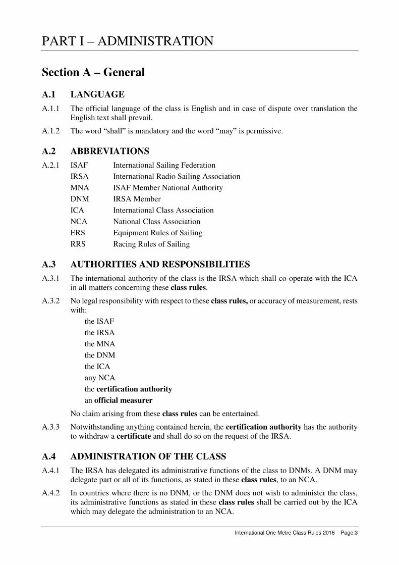
A.1 LANGUAGE
A.1.1 The official language of the class is English and in case of dispute over translation the
English text shall prevail.
A.1.2 The word “shall” is mandatory and the word “may” is permissive.
A.2 ABBREVIATIONS
A.2.1 ISAF International Sailing Federation
IRSA International Radio Sailing Association
MNA ISAF Member National Authority
DNM IRSA Member
ICA International Class Association
NCA National Class Association
ERS Equipment Rules of Sailing
RRS Racing Rules of Sailing
A.3 AUTHORITIES AND RESPONSIBILITIES
A.3.1 The international authority of the class is the IRSA which shall co-operate with the ICA
in all matters concerning these class rules.
A.3.2 No legal responsibility with respect to these class rules, or accuracy of measurement, rests
with:
the ISAF
the IRSA
the MNA
the DNM
the ICA
any NCA
the certification authority
an official measurer
No claim arising from these class rules can be entertained.
A.3.3 Notwithstanding anything contained herein, the certification authority has the authority
to withdraw a certificate and shall do so on the request of the IRSA.
A.4 ADMINISTRATION OF THE CLASS
A.4.1 The IRSA has delegated its administrative functions of the class to DNMs. A DNM may
delegate part or all of its functions, as stated in these class rules, to an NCA.
A.4.2 In countries where there is no DNM, or the DNM does not wish to administer the class,
its administrative functions as stated in these class rules shall be carried out by the ICA
which may delegate the administration to an NCA.

Page:4 International One Metre Class Rules 2016
A.5 ISAF RULES
A.5.1 These class rules shall be read in conjunction with the 2013-2016 ERS.
A.5.2 Except where used in headings, when a term is printed in “bold” the definition in the ERS
applies and when a term is printed in “italics” the definition in the RRS applies.
A.6 CHAMPIONSHIP RULES
A.6.1 The Class Championship Rules shall apply at World and Continental Championships.
A.7 SAILING INSTRUCTIONS
A.7.1 These class rules shall not be varied by sailing instructions except as provided by A.7.2.
A.7.2 At World or Continental Championships the sailing instructions may vary these class
rules only with the agreement of the ICA.
A.8 CLASS RULES AMENDMENTS
A.8.1 Amendments to these class rules shall be proposed by the ICA and are subject to the
approval of IRSA.
A.9 CLASS RULES INTERPRETATIONS
A.9.1 GENERAL
Interpretation of class rules, except as provided by A.9.2, shall be made in accordance
with the IOM ICA Regulations.
A.9.2 AT AN EVENT
Any interpretation of class rules required at an event may be made by an international
jury constituted in accordance with the RRS. Such interpretation shall only be valid during
the event and the organising authority shall, as soon as practical after the event, inform the
IRSA, the DNM and the ICA.
A.10 HULL REGISTRATION NUMBER
A.10.1 Registration numbers shall be issued by the certification authority.
A.10.2 Registration numbers shall be issued in consecutive order starting at “1”.
A.10.3 Each hull shall have a unique registration number which shall include the national letters
and the certification authority’s sequential registration number. Under no circumstances
may a registration number be used on a hull other than the hull on which it was first used.
A.11 CERTIFICATION
A.11.1 For a hull not previously certified, all items required by the measurement form(s) to be
measured shall be measured by an official measurer and the details of hull and owner
entered onto the certification measurement form.
A.11.2 The certification measurement form, and certification fee if required, shall be sent to
the certification authority in the country where the hull is to be registered within 4 weeks
after completion of certification measurement.
A.11.3 Upon receipt of a satisfactorily completed certification measurement form and
certification fee if required within the 4 week time limit, the certification authority
may issue a certificate.

International One Metre Class Rules 2016 Page:5
A.11.4 The certification authority shall retain the original certification measurement form,
which shall be transferred to the new certification authority upon request if the hull is
exported.
A.12 VALIDITY OF CERTIFICATE
A.12.1 A certificate becomes invalid upon:
(a) A change of ownership,
(b) Withdrawal by the certification authority,
(c) The issue of another certificate.
A.13 COMPLIANCE WITH CLASS RULES
A.13.1 A boat ceases to comply with the class rules upon:
(a) Use of equipment that does not comply with limitations in the class rules,
(b) Use of equipment that does not comply, or that causes the boat not to comply, with
limitations recorded on the certificate,
(c) Alteration or repair of equipment required by the measurement form(s) to be
measured, except where permitted by the class rules,
(d) A change of class rules that causes equipment in use to cease to be permitted, except
where the equipment may comply with the class rules in force at the time of its initial
certification measurement.
A.14 RE-CERTIFICATION
A.14.1 A hull may be issued with a new certificate, showing dates of initial and new certification
measurement as applicable:
(a) WHEN A CERTIFICATE BECOMES INVALID UPON CHANGE OF
OWNERSHIP
and the new owner applies to the certification authority in the country where the
hull is to be registered. The application shall include the old certificate and re-
certification fee if required. In the case of an imported hull the certification
authority shall request the certification measurement form from the previous
certification authority and a new hull registration number shall be issued,
(b) WHEN A CERTIFICATE HAS BEEN WITHDRAWN, OR WHEN THE
CERTIFICATE AND CERTIFICATION MEASUREMENT FORM CANNOT BE
LOCATED
and certification measurement as required for initial certification has been
undertaken.
A.14.2 A boat that has ceased to comply with the class rules may be brought into compliance:
(a) WHEN THE LIMITATIONS AFFECTING THE EQUIPMENT ARE IN THE
CLASS RULES
by carrying out certification measurement of affected equipment,
(b) WHEN THE LIMITATIONS AFFECTING THE EQUIPMENT ARE ON THE
CERTIFICATE
by carrying out certification measurement of affected equipment as required for
initial certification.
Page:6 International One Metre Class Rules 2016
Section B – Boat Eligibility
To be eligible to take part in racing, the rules in this section shall be complied with.
B.1 CERTIFICATE
B.1.1 The hull shall have a valid certificate.
B.1.2 A certificate issued prior to the effective date of these class rules remains valid until any
of the criteria in A.12.1 is met.
B.2 CLASS ASSOCIATION STICKER
B.2.1 A valid class association sticker, if required by the NCA or the ICA, shall be affixed to
the hull in a conspicuous position.
International One Metre Class Rules 2016 Page:7
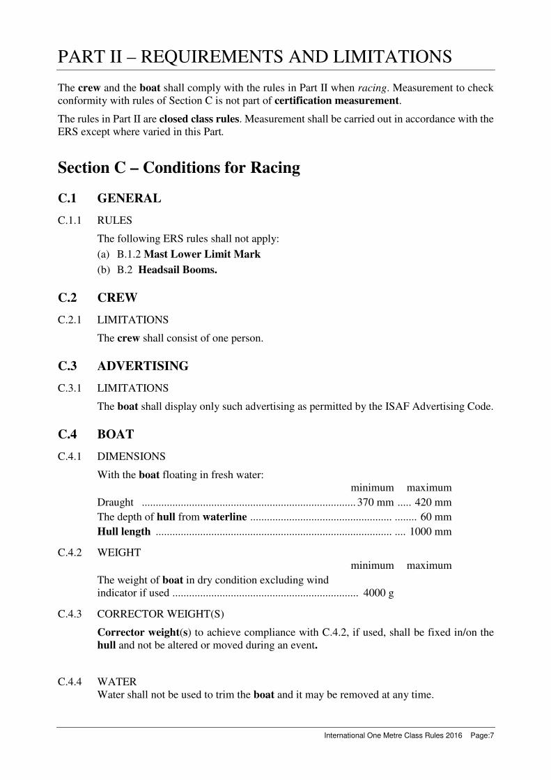
PART II – REQUIREMENTS AND LIMITATIONS
The crew and the boat shall comply with the rules in Part II when racing. Measurement to check
conformity with rules of Section C is not part of certification measurement.
The rules in Part II are closed class rules. Measurement shall be carried out in accordance with the
ERS except where varied in this Part.
Section C – Conditions for Racing
C.1 GENERAL
C.1.1 RULES
The following ERS rules shall not apply:
(a) B.1.2 Mast Lower Limit Mark
(b) B.2 Headsail Booms.
C.2 CREW
C.2.1 LIMITATIONS
The crew shall consist of one person.
C.3 ADVERTISING
C.3.1 LIMITATIONS
The boat shall display only such advertising as permitted by the ISAF Advertising Code.
C.4 BOAT
C.4.1 DIMENSIONS
With the boat floating in fresh water:
minimum maximum
Draught ............................................................................. 370 mm ..... 420 mm
The depth of hull from waterline ................................................... ........ 60 mm
Hull length ..................................................................................... .... 1000 mm
C.4.2 WEIGHT
minimum maximum
The weight of boat in dry condition excluding wind
indicator if used ................................................................... 4000 g
C.4.3 CORRECTOR WEIGHT(S)
Corrector weight(s) to achieve compliance with C.4.2, if used, shall be fixed in/on the
hull and not be altered or moved during an event.
C.4.4 WATER
Water shall not be used to trim the boat and it may be removed at any time.

Page:8 International One Metre Class Rules 2016
C.5 HULL
C.5.1 IDENTIFICATION
The hull registration number shall be displayed on the external surface of the hull shell or
deck clearly and legibly with a minimum height of 20 mm.
C.5.2 MAINTENANCE
Routine maintenance to the hull such as removing and adding fittings and remote control
equipment, replacing hull patches, painting, polishing, smoothing etc., is permitted
without re-measurement and re-certification provided the compliance with D.2 is not
affected.
C.5.3 REMOTE CONTROL EQUIPMENT
USE
(a) The rudder control unit shall control the rudder only.
(b) The sheet control unit shall control the mainsail sheet and headsail sheet only.
(c) Crew may use only the following radio transmissions from the boat:
(1) control unit positioning,
(2) radio link information,
(3) monitoring of onboard battery(s) conditions.
(d) During an event remote control and related equipment if temporarily removed and
or replaced:
(1) shall be refitted in the same position.
(2) shall be replaced by equipment of similar weight.
C.6 HULL APPENDAGES
C.6.1 MAINTENANCE
The hull appendages may be altered after certification measurement, without
undergoing new certification measurement, provided compliance with E.3 is not
affected.
C.6.2 LIMITATIONS
Except when a hull appendage has been lost or damaged beyond repair, only one keel
and one rudder shall be used during an event. Replacement may be made only with the
approval of the race committee. Unless the hull appendage has been lost, the race
committee shall remove or cancel any event limitation mark attached to the hull
appendage that has been replaced.
C.6.3 USE
(a) The keel shall not move or rotate relative to the hull, except by flexing.
(b) The hull appendages shall not project outboard of the hull.
(c) If removed:
(1) The keel shall be refitted in the same attitude and position in the hull.
(2) Parts of the keel shall be refitted in the same attitude and position relative to
the keel.
(3) The rudder shall be refitted in the same attitude and position relative to the
hull.

International One Metre Class Rules 2016 Page:9
C.6.4 WEIGHTS
minimum maximum
Keel, excluding fasteners to hull ........................................ 2200 g ....... 2500 g
Rudder, including stock ................................................................. ............ 75 g
C.7 RIG
C.7.1 LIMITATIONS
Except when an item has been lost or damaged beyond repair, one mast, one mainsail
boom and one headsail boom, for each of the three rigs, may be used during an event.
Replacement may be made only with the approval of the race committee. Unless the spar
is lost, the race committee shall remove or cancel any event limitation mark attached to
the spar that has been replaced.
C.7.2 USE
The rig shall not project beyond the fore and aft ends of the hull.
C.7.3 ADDED WEIGHTS
(a) Weights of any material may be positioned in and/or on a mast spar below the lower
point. Weights of density greater than 8000 kg/m3 may be positioned in and/or on a
mast spar above the lower point.
(b) Such weights may be removed or added at any time subject to C.4.1 and C.4.2.
C.7.4 MAST
(a) DIMENSIONS
minimum maximum
Lower point to deck limit mark
as defined in D.1.5 ................................................ 60 mm ..... 100 mm
Within these limits, the variation in height of
lower point for each rig ................................................... ....... ± 5 mm
Mast spar curvature between lower point and
upper point ..................................................................... unrestricted
(b) USE
The spar stepping position and wind indicator position are optional.
C.7.5 BOOMS
DIMENSIONS
minimum maximum
Boom spar curvature measured between points on
the top of the spar 10 mm from each end ................................ .......... 3 mm
C.7.6 STANDING RIGGING
USE
The headsail boom swivel shall be attached to the hull approximately on the hull
centreplane. The alignment of the swivel between the hull and the headsail boom shall
be controlled only by the rigging tension.

Page:10 International One Metre Class Rules 2016
C.7.7 RUNNING RIGGING
USE
(a) The mainsail sheet and the headsail sheet may be worked by a sheet control line
attached to the sheet control unit.
(b) The upper end of any headsail boom topping lift shall be attached to the headsail
halyard and/or stay, or their mast spar fitting(s).
(c) A headsail boom topping lift restraint line(s) attached to, or passing around, the
topping lift may be attached to and/or passed around any or all of the following:
topping lift; headsail; headsail halyard; headsail stay; headsail boom.
(d) A mainsail tack control line may be passed around or through the mast spar, the
mainsail boom spar and/or their fittings.
C.8 SAILS
C.8.1 MAINTENANCE
Routine maintenance such as replacement of battens and patching over damaged areas is
permitted without re-measurement and re-certification.
C.8.2 LIMITATIONS
Except when a sail has been lost or damaged beyond repair, no more than one mainsail
and one headsail, for each rig, shall be used during an event. Replacement may be made
only with the approval of the race committee. Unless the sail is lost, the race committee
shall remove or cancel any event limitation mark attached to the sail that has been
replaced.
C.8.3 IDENTIFICATION
Identification shall comply with the RRS. Sails certified before 1st January 2005 shall
comply with the sail identification rules in force at that time or at the time of certification
measurement.
C.8.4 USE
(a) GENERAL
(1) A sail of one rig shall not be used with another rig.
(2) A sail may not be used alone, except where the other sail of that rig has been lost
or damaged during the race.
(b) MAINSAIL
(1) The tack point shall not be set more than 25 mm forward of the forward end of
the boom spar and the clew point shall not be set more than 25 mm aft of the aft
end of the boom spar.
(2) Any luff bolt rope or luff slides shall be set in a mast spar track.
(3) Luff tabling may envelop a mast spar jackstay.
(c) HEADSAIL
(1) A line taken through the tack point and the head point shall cut the forward face
of the mast spar lower than the lower edge of the headsail stay limit mark at
the fore side of the spar when the boom spar is on the centreplane of the hull.
(2) The tack point shall not be set more than 25 mm forward of the forward end of
the boom spar and the clew point shall not be set more than 25 mm aft of the aft
end of the boom spar.

International One Metre Class Rules 2016 Page:11
(3) Luff tabling may envelop the headsail stay.
(4) Any luff slides shall be set on the headsail stay.
Section D – Hull
D.1 GENERAL
D.1.1 RULES
The hull shall either comply with the class rules in force at the time of its initial
certification measurement or comply with the current class rules.
D.1.2 CERTIFICATION
See rule A.11.
D.1.3 BUILDERS
(a) No building licence is required for hulls built in accordance with D.2.1.
(b) A building licence may be granted to commercial builders who wish to use mass
production methods to lower the cost of hulls, but which do not comply with D.2.1.
Such licence shall be based on a building specification approved by the ICA and the
IRSA and a contract between the IRSA and the builder.
D.1.4 IDENTIFICATION
The hull registration number shall be marked in an easily visible location on a non-
removable part of the hull excluding fittings and corrector weights by any of the
following means: painting on, engraving in, bonding in, moulding in.
D.1.5 DECK LIMIT MARK
The deck limit mark shall be displayed on the centreplane of the hull near to the mast
position. It shall be a minimum of 5 mm in diameter.
D.2 HULL
D.2.1 MATERIALS
(a) Subject to (b) and (c), the hull, excluding fittings and remote control equipment but
including any supports and containers for such items, shall be made of and joined
using one or more of the following materials:
(1) Metal,
(2) Wood; wood based products containing only permitted materials,
(3) Resin, which may be coloured and/or reinforced with glass fibres,
(4) Adhesive,
(5) Varnish; paint,
(6) Film covering materials which may be fibre reinforced,
(7) Elastomeric material,
(8) Thermoplastic, which may be moulded, containing only permitted materials.
(b) With the exception of elastomeric materials, materials shall not be: expanded,
foamed, honeycombed.

Page:12 International One Metre Class Rules 2016
(c) Unrestricted by (a) and (b):
(1) A builder’s mark may be applied,
(2) The hull registration number shall be applied.
(3) A hull made with Texalium and with a date of initial fundamental
measurement, prior to 1 September 2004 may be certified.
D.2.2 CONSTRUCTION
Construction is unrestricted subject to the following:
(a) The hull shall be a monohull.
(b) Except for trunking for the keel and rudder, the hull shall not have:
(1) Voids in the waterplane and/or the underwater profile,
(2) Hollows in the plan view and/or the underwater profile that exceed 3 mm,
(3) Transverse hollows in the undersurface of the hull that exceed 3 mm when tested
parallel to the waterplane as in figure H.2.
(c) The forward 10 mm of the hull shall be of elastomeric material.
(d) The rudder shall be attached to the hull aft of where the keel is attached.
D.2.3 FITTINGS
Fittings are unrestricted except that:
(a) Fittings that can contribute to the stiffness and/or strength and/or watertight integrity
of the hull shall be of materials permitted by D.2.1.
(b) Ball and/or roller bearings may only be used for: sheet control line blocks, mainsail
boom sheet blocks and headsail boom sheet blocks.
(c) Fittings shall not project outboard of the hull shell or deck.
D.2.4 REMOTE CONTROL EQUIPMENT
(a) The following is permitted:
(1) One or more receivers.
(2) One rudder control unit.
(3) One sheet control unit.
(4) Battery cells assembled in one or more packs.
(5) Electric cables, connectors and switches.
(6) One device to indicate the battery voltage. In addition, items listed under (1) to
(5) may have their own built-in battery voltage indication.
(7) A device to control downstream voltage delivered to permitted radio control
equipment as defined by items listed under (1) to (6) of this rule.
(b) The rudder control unit and the sheet control unit may contain ball and/or roller
bearings.
(c) Remote control equipment may be fastened using hook and loop fasteners and/or the
materials listed in D.2.1(a).

International One Metre Class Rules 2016 Page:13
Section E – Hull Appendages
E.1 PARTS
E.1.1 MANDATORY
(a) Keel, which may comprise a fin and a bulb.
(b) Rudder
E.2 GENERAL
E.2.1 RULES
Hull appendages shall comply with the current class rules.
E.2.2 BUILDERS
No licence is required.
E.3 KEEL AND RUDDER
E.3.1 MATERIALS
Materials shall not be of density higher than lead (11300 kg/m3).
E.3.2 CONSTRUCTION
Construction is unrestricted subject to the following:
(a) The keel and rudder shall be removable from the hull.
(b) The keel and rudder shall not
(1) be connected,
(2) be articulated,
(3) have openings through which water could flow when in use.
E.4 KEEL
E.4.1 DIMENSIONS
minimum maximum
The largest transverse dimension except for the
lowest 60 mm .......................................................................... ........ 20 mm
Section F – Rig
F.1 PARTS
F.1.1 MANDATORY
(a) Mast.
(b) Mainsail boom.
(c) Headsail boom.
(d) Standing rigging.
(e) Running rigging.
(f) Fittings.

Page:14 International One Metre Class Rules 2016
F.2 GENERAL
F.2.1 RULES
Rigs shall comply with the current class rules.
F.2.2 MANUFACTURERS
No licence is required.
F.2.3 LIMITATIONS
The function of items shall be limited to what is normally provided by items of their type.
F.2.4 CONSTRUCTION
(a) Fittings and/or control lines may be combined provided their function is not extended
beyond what is permitted.
(b) The position of parts, and the length and tension of rigging, may be adjustable unless
otherwise restricted.
(c) Ball and/or roller bearings may be used for: kicking strap fitting; gooseneck; mainsail
boom sheet blocks; headsail boom sheet blocks; headsail boom swivel.
(d) Where the mast kicking strap fitting and/or gooseneck:
(1) are exposed,
(2) are not of circular cross section, and
(3) rotate,
they shall not exceed 20 mm in any cross section perpendicular to the axis of rotation.
F.3 MAST
F.3.1 MATERIALS
(a) The spar shall be aluminium alloy of 2024, 5754, 6005, 6060, 6061, 6063, 6082 or
7075 grade, or wood.
(b) Other permitted materials in the spar are: adhesive; paint; powder coat; varnish; wax.
An aluminium alloy spar may be anodised.
F.3.2 CONSTRUCTION
(a) A mast stub arrangement is permitted and, if used, shall be taken to be part of the
mast spar.
(b) Between the lower point and the upper point the spar section shall be:
(1) of circular outer shape,
(2) constant
within the variations permitted by F.3.4 except for the following permitted items:
an internal sail track,
local cutaways for the insertion of a bolt rope or slides, openings for fittings
and/or rigging, internal and/or external spar joiners.
(c) Limit marks may be applied by the following means:
(1) paint,
(2) self adhesive tape,
(3) fittings.
International One Metre Class Rules 2016 Page:15
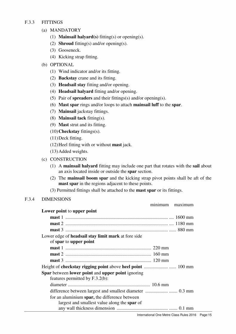
F.3.3 FITTINGS
(a) MANDATORY
(1) Mainsail halyard(s) fitting(s) or opening(s).
(2) Shroud fitting(s) and/or opening(s).
(3) Gooseneck.
(4) Kicking strap fitting.
(b) OPTIONAL
(1) Wind indicator and/or its fitting.
(2) Backstay crane and its fitting.
(3) Headsail stay fitting and/or opening.
(4) Headsail halyard fitting and/or opening.
(5) Pair of spreaders and their fittings(s) and/or opening(s).
(6) Mast spar rings and/or loops to attach mainsail luff to the spar.
(7) Mainsail jackstay fittings.
(8) Mainsail tack fitting(s).
(9) Mast strut and its fitting.
(10) Checkstay fittings(s).
(11) Deck fitting.
(12) Heel fitting with or without mast jack.
(13) Added weights.
(c) CONSTRUCTION
(1) A mainsail halyard fitting may include one part that rotates with the sail about
an axis located inside or outside the spar section.
(2) The mainsail boom spar and the kicking strap pivot points shall be aft of the
mast spar in the regions adjacent to these points.
(3) Permitted fittings shall be attached to the mast spar or its fittings.
F.3.4 DIMENSIONS
minimum maximum
Lower point to upper point
mast 1 ...................................................................................... .... 1600 mm
mast 2 ...................................................................................... .... 1180 mm
mast 3 ...................................................................................... ...... 880 mm
Lower edge of headsail stay limit mark at fore side
of spar to upper point
mast 1 ........................................................................ 220 mm
mast 2 ........................................................................ 160 mm
mast 3 ........................................................................ 120 mm
Height of checkstay rigging point above heel point .................... ...... 100 mm
Spar between lower point and upper point ignoring
features permitted by F.3.2(b):
diameter ..................................................................... 10.6 mm
difference between largest and smallest diameter ................... ....... 0.3 mm
for an aluminium spar, the difference between
largest and smallest value along the spar of
any wall thickness dimension ........................................... ....... 0.1 mm
Page:16 International One Metre Class Rules 2016
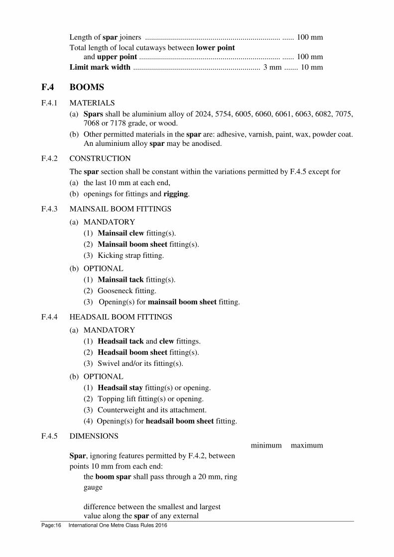
Length of spar joiners .................................................................... ...... 100 mm
Total length of local cutaways between lower point
and upper point ....................................................................... ...... 100 mm
Limit mark width ................................................................ 3 mm ....... 10 mm
F.4 BOOMS
F.4.1 MATERIALS
(a) Spars shall be aluminium alloy of 2024, 5754, 6005, 6060, 6061, 6063, 6082, 7075,
7068 or 7178 grade, or wood.
(b) Other permitted materials in the spar are: adhesive, varnish, paint, wax, powder coat.
An aluminium alloy spar may be anodised.
F.4.2 CONSTRUCTION
The spar section shall be constant within the variations permitted by F.4.5 except for
(a) the last 10 mm at each end,
(b) openings for fittings and rigging.
F.4.3 MAINSAIL BOOM FITTINGS
(a) MANDATORY
(1) Mainsail clew fitting(s).
(2) Mainsail boom sheet fitting(s).
(3) Kicking strap fitting.
(b) OPTIONAL
(1) Mainsail tack fitting(s).
(2) Gooseneck fitting.
(3) Opening(s) for mainsail boom sheet fitting.
F.4.4 HEADSAIL BOOM FITTINGS
(a) MANDATORY
(1) Headsail tack and clew fittings.
(2) Headsail boom sheet fitting(s).
(3) Swivel and/or its fitting(s).
(b) OPTIONAL
(1) Headsail stay fitting(s) or opening.
(2) Topping lift fitting(s) or opening.
(3) Counterweight and its attachment.
(4) Opening(s) for headsail boom sheet fitting.
F.4.5 DIMENSIONS
minimum maximum
Spar, ignoring features permitted by F.4.2, between
points 10 mm from each end:
the boom spar shall pass through a 20 mm, ring
gauge
difference between the smallest and largest
value along the spar of any external

International One Metre Class Rules 2016 Page:17
dimension .................................................................................. ....... 0.5 mm
for an aluminium spar, the difference between
the largest and smallest value along the
spar of any wall thickness dimension ..................................... ....... 0.1 mm
F.5 STANDING RIGGING
F.5.1 MATERIALS
Except for terminations and the headsail boom swivel, the standing rigging shall be of
steel and/or polymer.
F.5.2 CONSTRUCTION
(a) MANDATORY
(1) Pair of shrouds.
(2) Headsail boom swivel.
(b) OPTIONAL
(1) Pair of checkstays if a mast strut is not fitted.
(2) A headsail stay less than 1 mm in diameter.
(3) A mast spar jackstay less than 1 mm in diameter.
F.5.3 FITTINGS
OPTIONAL
(a) Terminations.
(b) Length and tension adjustments.
F.6 RUNNING RIGGING
F.6.1 MATERIALS
Materials of running rigging are unrestricted.
F.6.2 CONSTRUCTION
(a) MANDATORY
(1) Mainsail boom sheet.
(2) Mainsail boom kicking strap.
(3) Headsail halyard, if headsail stay is not fitted.
(4) Headsail boom sheet.
(5) Backstay.
(b) OPTIONAL
(1) Mainsail halyard(s).
(2) Mainsail clew trim line.
(3) Mainsail tack trim line
(4) Headsail halyard(s).
(5) Headsail clew trim line.
(6) Headsail tack trim line.
(7) Headsail boom topping lift.
(8) Headsail boom topping lift restraint line(s).

Page:18 International One Metre Class Rules 2016
F.6.3 FITTINGS
OPTIONAL
(a) Terminations.
(b) Length and tension adjustments.
(c) Mainsail boom sheet blocks, headsail boom sheet blocks.
(d) A wind indicator attached to the backstay.
Section G – Sails
G.1 PARTS
G.1.1 MANDATORY
(a) Mainsail.
(b) Headsail.
G.2 GENERAL
G.2.1 RULES
Sails shall comply with the class rules in force at the time of their initial certification
measurement.
G.2.2 CERTIFICATION
(a) The official measurer shall certify sails in the tack and shall date each with the date
of certification measurement.
(b) An MNA may appoint one or more persons at a sailmaker to measure and certify
sails produced by that manufacturer. A special licence shall be awarded for that
purpose.
G.2.3 SAILMAKERS
No licence is required.
G.2.4 DEFINITIONS
Batten Point
The batten point is defined as the intersection of the leech and
(a) the extended centreline of the batten or
(b) a line of minimum length 20 mm marked on the leech if there is no batten.
G.2.5 MEASUREMENT
(a) During measurement:
(1) battens need not be removed,
(2) mainsails with the luff not set in a mast spar track may be attached to spars,
(3) a headsail stay and mainsail mast spar jackstay need not be removed.
(4) tell tales shall be ignored.
(b) Where a mainsail has a luff bolt rope the luff shall be taken as the aft edge of the bolt
International One Metre Class Rules 2016 Page:19
rope.
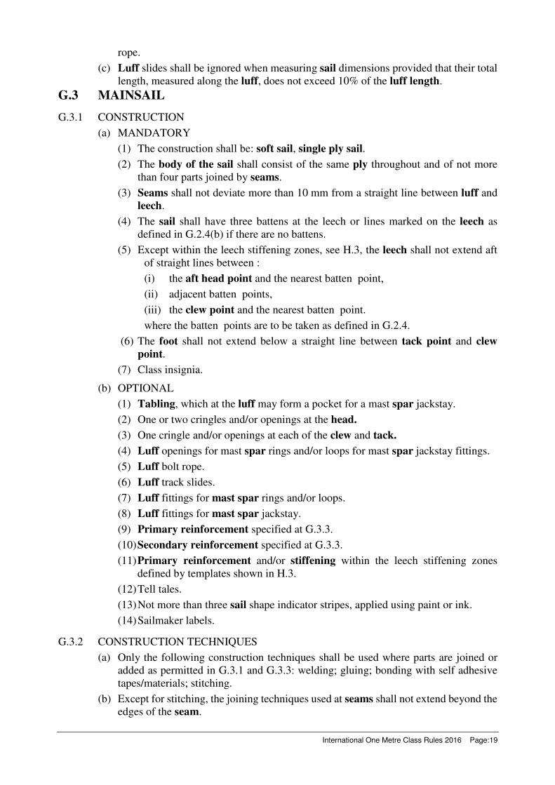
(c) Luff slides shall be ignored when measuring sail dimensions provided that their total
length, measured along the luff, does not exceed 10% of the luff length.
G.3 MAINSAIL
G.3.1 CONSTRUCTION
(a) MANDATORY
(1) The construction shall be: soft sail, single ply sail.
(2) The body of the sail shall consist of the same ply throughout and of not more
than four parts joined by seams.
(3) Seams shall not deviate more than 10 mm from a straight line between luff and
leech.
(4) The sail shall have three battens at the leech or lines marked on the leech as
defined in G.2.4(b) if there are no battens.
(5) Except within the leech stiffening zones, see H.3, the leech shall not extend aft
of straight lines between :
(i) the aft head point and the nearest batten point,
(ii) adjacent batten points,
(iii) the clew point and the nearest batten point.
where the batten points are to be taken as defined in G.2.4.
(6) The foot shall not extend below a straight line between tack point and clew
point.
(7) Class insignia.
(b) OPTIONAL
(1) Tabling, which at the luff may form a pocket for a mast spar jackstay.
(2) One or two cringles and/or openings at the head.
(3) One cringle and/or openings at each of the clew and tack.
(4) Luff openings for mast spar rings and/or loops for mast spar jackstay fittings.
(5) Luff bolt rope.
(6) Luff track slides.
(7) Luff fittings for mast spar rings and/or loops.
(8) Luff fittings for mast spar jackstay.
(9) Primary reinforcement specified at G.3.3.
(10) Secondary reinforcement specified at G.3.3.
(11) Primary reinforcement and/or stiffening within the leech stiffening zones
defined by templates shown in H.3.
(12) Tell tales.
(13) Not more than three sail shape indicator stripes, applied using paint or ink.
(14) Sailmaker labels.
G.3.2 CONSTRUCTION TECHNIQUES
(a) Only the following construction techniques shall be used where parts are joined or
added as permitted in G.3.1 and G.3.3: welding; gluing; bonding with self adhesive
tapes/materials; stitching.
(b) Except for stitching, the joining techniques used at seams shall not extend beyond the
edges of the seam.

Page:20 International One Metre Class Rules 2016
G.3.3 DIMENSIONS
minimum maximum
Leech length:
mainsail 1 ................................................................ 1610 mm ... 1620 mm
mainsail 2 ................................................................ 1200 mm ... 1210 mm
mainsail 3 .................................................................. 910 mm ..... 920 mm
Foot length:
mainsail 1 .................................................................. 350 mm ..... 360 mm
mainsail 2 .................................................................. 340 mm ..... 350 mm
mainsail 3 .................................................................. 310 mm ..... 320 mm
Quarter width:
mainsail 1 .................................................................. 305 mm ..... 315 mm
mainsail 2 .................................................................. 295 mm ..... 305 mm
mainsail 3 .................................................................. 265 mm ..... 275 mm
Half width:
mainsail 1 .................................................................. 235 mm ..... 245 mm
mainsail 2 .................................................................. 225 mm ..... 235 mm
mainsail 3 .................................................................. 205 mm ..... 215 mm
Three-quarter width:
mainsail 1 .................................................................. 135 mm ..... 145 mm
mainsail 2 .................................................................. 130 mm ..... 140 mm
mainsail 3 .................................................................. 115 mm ..... 125 mm
Top width ....................................................................................... ........ 20 mm
Primary reinforcement:
from nearest sail corner measurement point ........................ ...... 125 mm
Secondary reinforcement:
from nearest sail corner measurement point ........................ ...... 125 mm
for flutter patches ................................................................... ........ 50 mm
at luff fittings, luff slides and/or luff openings ....................... ........ 20 mm
Tabling width ................................................................................ ........ 15 mm
Seam width .................................................................................... ........ 15 mm
Seam to nearest sail corner measurement point ............ 150 mm
Batten length:
middle and lower ..................................................................... ...... 100 mm
upper ........................................................................................ ........ 75 mm
Batten width .................................................................................... ........ 10 mm
Batten point, as defined in G.2.4, to nearest leech point …………….... 20 mm
Largest cringle dimension ............................................................... ........ 10 mm
With the exception for luff slides, largest luff fitting
dimension ................................................................................. ........ 10 mm
Sail shape indicator stripe width .............................................. ........ 30 mm

International One Metre Class Rules 2016 Page:21
G.4 HEADSAIL
G.4.1 CONSTRUCTION
(a) MANDATORY
(1) The construction shall be: soft sail, single ply sail.
(2) The body of the sail shall consist of the same ply throughout and of not more
than three parts joined by seams.
(3) Seams shall not deviate more than 10 mm from a straight line between luff and
leech.
(4) Except within the leech stiffening zones, see H.3, the leech shall not extend aft
of a straight line between the aft head point and the clew point.
(5) The foot shall not extend below a straight line between tack point and clew
point.
(b) OPTIONAL
(1) Tabling, which at the luff may form a pocket for a headsail stay.
(2) One or two cringles and/or openings at the head.
(3) One cringle and/or openings at each of the clew and tack.
(4) Headsail stay slides and/or loops.
(5) Primary reinforcement specified at G.4.3.
(6) Secondary reinforcement specified at G.4.3.
(7) Not more than two battens at the leech.
(8) Primary reinforcement and/or stiffening within the leech stiffening zones
defined by templates as shown in H.3.
(9) Tell tales.
(10) Not more than two sail shape indicator stripes, applied using paint or ink.
(11) Sailmaker labels.
G.4.2 CONSTRUCTION TECHNIQUES
(a) Only the following construction techniques shall be used where parts are joined or
added as permitted in G.4.1 and G.4.3: welding; gluing; bonding with self adhesive
tapes/materials; stitching.
(b) Except for stitching, the joining techniques used at seams shall not extent beyond
the edges of the seam.
Page:22 International One Metre Class Rules 2016
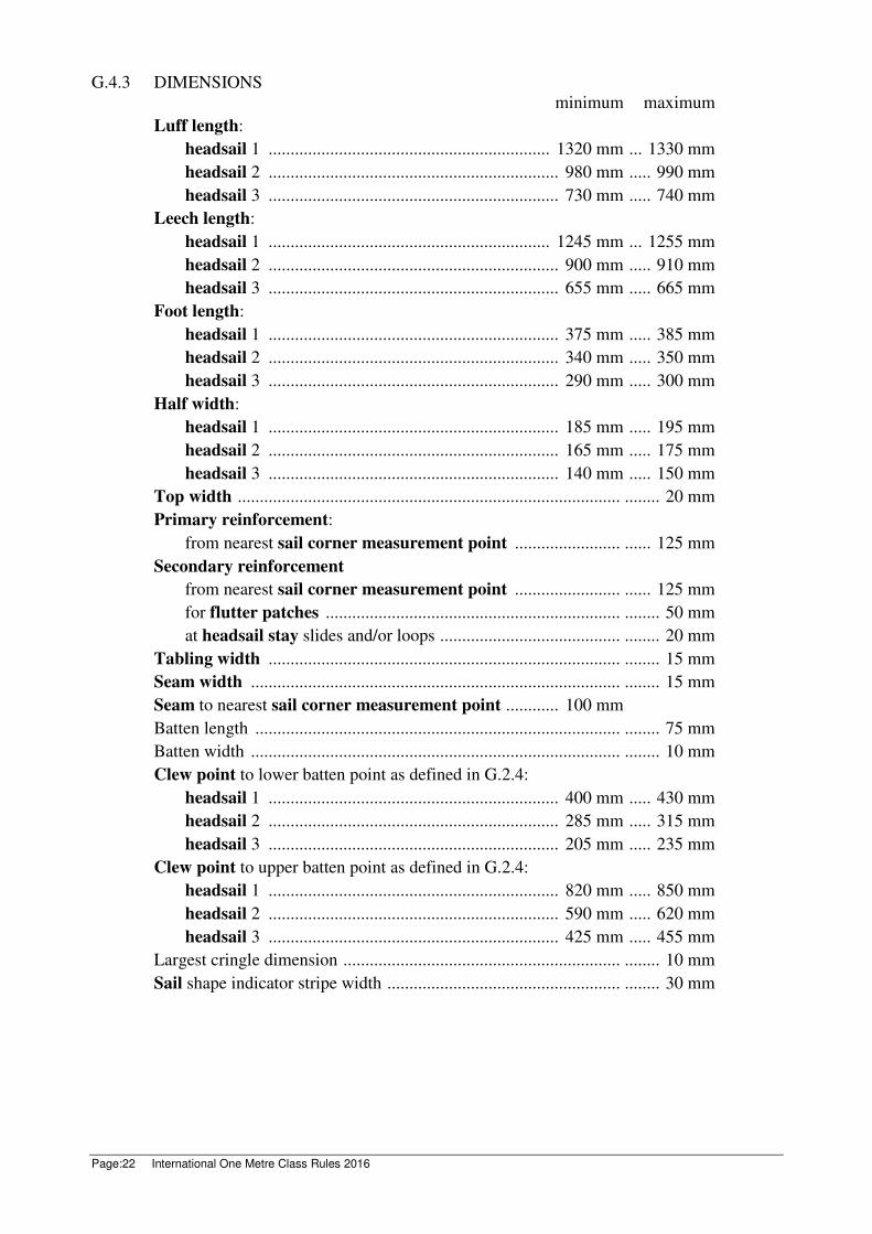
G.4.3 DIMENSIONS
minimum maximum
Luff length:
headsail 1 ................................................................ 1320 mm ... 1330 mm
headsail 2 .................................................................. 980 mm ..... 990 mm
headsail 3 .................................................................. 730 mm ..... 740 mm
Leech length:
headsail 1 ................................................................ 1245 mm ... 1255 mm
headsail 2 .................................................................. 900 mm ..... 910 mm
headsail 3 .................................................................. 655 mm ..... 665 mm
Foot length:
headsail 1 .................................................................. 375 mm ..... 385 mm
headsail 2 .................................................................. 340 mm ..... 350 mm
headsail 3 .................................................................. 290 mm ..... 300 mm
Half width:
headsail 1 .................................................................. 185 mm ..... 195 mm
headsail 2 .................................................................. 165 mm ..... 175 mm
headsail 3 .................................................................. 140 mm ..... 150 mm
Top width ....................................................................................... ........ 20 mm
Primary reinforcement:
from nearest sail corner measurement point ........................ ...... 125 mm
Secondary reinforcement
from nearest sail corner measurement point ........................ ...... 125 mm
for flutter patches ................................................................... ........ 50 mm
at headsail stay slides and/or loops ......................................... ........ 20 mm
Tabling width ................................................................................ ........ 15 mm
Seam width .................................................................................... ........ 15 mm
Seam to nearest sail corner measurement point ............ 100 mm
Batten length ................................................................................... ........ 75 mm
Batten width .................................................................................... ........ 10 mm
Clew point to lower batten point as defined in G.2.4:
headsail 1 .................................................................. 400 mm ..... 430 mm
headsail 2 .................................................................. 285 mm ..... 315 mm
headsail 3 .................................................................. 205 mm ..... 235 mm
Clew point to upper batten point as defined in G.2.4:
headsail 1 .................................................................. 820 mm ..... 850 mm
headsail 2 .................................................................. 590 mm ..... 620 mm
headsail 3 .................................................................. 425 mm ..... 455 mm
Largest cringle dimension ............................................................... ........ 10 mm
Sail shape indicator stripe width ..................................................... ........ 30 mm

International One Metre Class Rules 2016 Page:23
PART III – APPENDICES
Section H – Illustrations
H.1 CLASS INSIGNIA
H.2 TRANSVERSE HULL HOLLOWS
Rule D.2.2(b)(3)
The hull shall not have transverse hollows in the undersurface of the hull that exceed 3
mm when tested parallel to the waterplane.

Page:24 International One Metre Class Rules 2016
H.3 LEECH STIFFENING ZONE
H.3.1 DEFINITION
A leech stiffening zone is a part of a sail that may be covered by a leech stiffening zone
template as described in H.3.2 and positioned as described in H.3.3.
H.3.2 TEMPLATE AND TEMPLATE DATUM POINT
Leech stiffening zone template Length, L
Mainsail middle and lower……………………………… 120
Mainsail upper and headsail template…………………… 95
H.3.3 TEMPLATE POSITIONING
It shall be possible to position the template so that
(1) its datum point is over the relevant batten point,
(2) its long edges cut the leech and
(3) it covers any primary reinforcement and/or stiffening.
Effective: 1 March 2016
Previous issues: March 1988, March 1989, May 1992, amended June 1994, June 1995, 1 March
2002, 15 May 2003, 1 April 2007, 5 November 2009, 13 February 2011, 30
March 2012, 1 March 2013, 1 March 2015
© 2016, International One Metre International Class Association (IOM ICA)