rechargeable batteries, old and new john b. goodenough the ... · rechargeable batteries, old and...
TRANSCRIPT

Rechargeable Batteries, Old and NewJohn B. Goodenough
The University of Texas at Austin
Modern Society is enabled by the chemical energy stored in fossil fuels.Unsustainable Cost• National vulnerabilities from uneven, finite
distribution• Spoiled environment by extraction• Air pollution and global warming by use

Sustainable Energy Supply
• Generation of electrical energy by wind, solar, nuclear, and other sources
• Storage of electrical energy at an acceptable cost
• What is the status of rechargeable batteries? Electrochemical capacitors?

Battery Principle
Rechargeable Electrochemical Cell: Pcharge > Pdischarge Battery=Stack of cells connected in series to increase V, in
parallel (or electrode area) to increase I=dq/dt and/or Δt. Challenges: Cost, Safety, Energy Density, Life, Rate.
Chemical Energy(in electrodes)
Electrical Energy(P=IV for Δt)
I, V
Δt
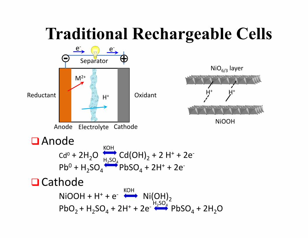
Traditional Rechargeable Cells
AnodeCd0 + 2H2O Cd(OH)2 + 2 H+ + 2e‐
Pb0 + H2SO4 PbSO4 + 2H+ + 2e‐
CathodeNiOOH + H+ + e‐ Ni(OH)2PbO2 + H2SO4 + 2H+ + 2e‐ PbSO4 + 2H2O
Reductant Oxidant
Anode CathodeElectrolyte
‐ +Separator
e‐e‐
M2+
H+
NiO6/3 layer
NiOOH
H+ H+
KOH
H2SO4
H2SO4
KOH

Vdis
Vocdis
I
(i) (ii) (iii)
Vdis = Voc − ηdis(I,q) Relectrolyte = (dV/dI)ii
Vch = Voc + ηch(I,q)
TYPICAL BATTERY DISCHARGE

V
t or q
VV
t or q
Two Phase
η
V
t or q
VOC
Diffusion‐limited (end of life)
VV
t or q
η
(i) (ii) (iii)
VOC
Cell Energy at Constant I = dq/dt
V(q) = VOC – η(q, I); VOC = (μA – μC)/e ≤ electrolyte Eg
η(q, I) increases with resistance to working-ion current
Problem: Maximize VOC, Q(I) and # cycles to Q/Q0 = 0.8; minimize η
Q(I)/wt or vol = specific or volumetric capacity
Energy = ; ∆ ∆

Electrolyte
Aqueous Electrolyte: Eg = 1.23 eV• LUMO = H2O/H2; HOMO = O2/H2O
Kinetic Stability• NiOOH/KOH/Cdo Voc = 1.5 V
Limited Life• PbO2/H2SO4/Pbo Voc = 2.0 V

LUMO
HOMO
1.1 eV
0.3 eV
4 eVoc
EF(Li)
3.2 eV
Electrolyte, Separator LixCLi1‐xCoO2
E
O2‐:2p6
Co4+/Co3+
S2‐:3p6
2.6 eV
First Li-ion Battery

LiCoO2//C Cell
SEI layer
Separator
LixC6Li1‐xCoO2

Lix[M2]O4 Spinel Electrodes
a0
8a16c
16dO2‐
2 quadrants of structureEdge‐shared MO6/5 octahedra3D Li+ insertion into close‐packed oxygen array
Note: Li1+x[Li1/3Ti5/3]O4: V=1.5 VLi1‐x[Ni0.5Mn1.5]O4: V=4.7 VNi(II) Ni(IV) with little step
Lix[Mn2]O4

NASICON Framework
NASICON
Na1+3xZr2(P1-xSixO4)3
LixFe2(SO4)3: V =3.6 V
LixFe2(MO4)3: M = Mo, W: V =3.0 V
Na3-xV2(PO4)3: V = 3.4 V
c
a

Capacity Challenge(Limited specific capacity further reduced by anode
SEI layer)
0 50 100 150 2001.5
2.0
2.5
3.0
3.5
4.0
4.5
5.0
Pot
entia
l (V
) vs.
Li+ /L
i
Capacity (mAh/g)0 50 100 150 200 250 300
2.0
2.5
3.0
3.5
4.0
4.5
5.0
Pot
entia
l (V
) vs.
Li+ /L
i
Capacity (mAh/g)
Li1‐xCoO2
Li1‐xFePO4
LixTiS2& Li2[Ti2]S4
Lix[Mn2]O4
Li1‐x[Ni0.5Mn1.5]O4

MO2
LiMO2
Li MO2
Li MO2
ELECTRODE MATERIALS
LUMO
Na2MnFe(CN)6 and Na3V2(PO4)3 : V 3.4 V, Q(10C) > 100 mAh/g

Framework of Prussian Blue Analogues

Anode Problem with Organic Liquid Electrolyte
• An EF (Anode) > LUMO requires an SEI• SEI on Li0 or Na0 creates dendrites, so C
anode• Need VCh < Vplate, so C-buffered alloys• Need SEI permeable to Li+ or Na+: if Li+,
Na+ come from cathode, get capacity loss on initial charge.
• Reforming SEI gives capacity fade limiting cycle life
• SEI slows Li+ or Na+ transfer

Separators
• Celgard membrane: penetrated by dendrites; insertion-compound cathode
• Polymer-gel membranes: blocks dendrites; adds choice of liquid flow-through cathode
• Anode/Solid-electrolyte interface: prevents dendrites, allows choice of sulfur or liquid flow-through and air cathode if solid electrolyte stable in alkaline water

Al2O3/PEO Separator(K.S. Park, J.-H. Cho, C.J. Ellison
Oxide: Dried (400C) Al2O3 Powder (300-400nm)Polymer: DEGDVE = Di(ethyleneglycol) divnylether with ethylne-
oxide (EO) units PETT = tetrathiol crosslinker
Preparation: AIBN = thermal initiator (80C, 4h)Yield: Quantitative, homogeneous network
AIBN = Azobisisobutyrolnitrile

Photographs of a PEO/Al2O3 (2/1 in weight) composite membrane (25 20 cm2)
PEO/Al2O3 Composite-Membrane SeparatorK. Park et al.

Mechanical Stability
• Tensile test shows a good mechanical stability, especially after Al2O3incorporation.
• Stability against Li dendrite
Minor surface dent by Li dendriteAfter full charging
It blocks Li dendrite.

Presence of Osmosis• Presence of concentration gradient of a redox-molecule across the PEO/Al2O3
membrane
• Balancing the concentrations between catholyte and anolyte is necessary, for example, with high-molecular-weight Ionic liquids and PEGDME.

Charge/Discharge Cycle Property
Anolyte: 1M LiTFSI in EC.DEC w/0.1M PEGDME 500Catholyte: 1M LiTFSI in EC/DEC w/0.1M 6-Bromohexyl ferrocene

0 10 20 30 40 500
40
80
120 0.5 C2 C1 C0.5 C
GF/PVDF-HFP/PDA GF/PVDF-HFP Glass fiber
Spe
cific
Cap
acity
(mA
h g-1
)
Cycle number
0.2 C
PVDF‐HFP: Widely used as host for gel‐polymerelectrolytesBut with unsatisfactory mechanical strengthGlass‐fiber paper: Used to enhance the mechanical properties
Polydopamine: Biomimetic polymer of mussel adhesive protein Polymerized at room temperature in aqueous solutionModify the surface properties of PVDF‐HFP
Gel‐polymer electrolytes: Improve rate and cycle performance of air‐dried cathode of Na2MnFe(CN)6The composite membranes have good thermal
stability and mechanical strength. Hongcai Gao, et al. Adv Energy Mater 2015

Current collector
Separator membrane
Solid electrolyte
cathode
Current collector
Separator membrane
cathode
Li+/Na+
Strategy for an Alkali-Metal Anode

Cost Targets• Cycle Life N > 10,000; calendar life
10 years
• Simple processing of inexpensive materials.
• Increased VQ(I) to reduce number of cells.
• Simplify battery management

Lithium-Sulfur Batteries