recent advances in variable fidelity mdo framework for
TRANSCRIPT

Recent Advances in Variable Fidelity MDO Framework for Collaborative and Integrated
Aircraft Configuration Development - CEASIOM
Mengmeng Zhang1 & Arthur Rizzi2
1Airinnova AB, 2Royal Institute of Technology (KTH)
Stockholm, 2015
1CEAS-TCAD, 12-14 October 2015Naples, Italy
Overview and Summary
• Introduction to aircraft conceptual-preliminary design
• Software for aircraft conceptual-preliminary design
• Wing design methodology
• Results and discussion of selected design studies
• Conclusions
2CEAS-TCAD, 12-14 October 2015Naples, Italy

Co
mp
lexity
Systems- Propulsion Airframe Integration- Wing aero- Controls- ⁞
Components design- Components
Nuts & Bolts- Isolated physics- Single physics
Right answer for the right reason
Top down: Requirements-based priorities for design concept
AircraftSystem of systems
Hie
rarc
hic
al d
ecom
positio
nH
igh-f
idelit
y p
redic
tions
Re-engineering the aircraft design process Goal From functional-oriented approachto an integration of all disciplines
Hig
h F
idel
ity
Pred
icti
on
s
Co
ncep
t D
esignP
relimin
ary D
esignD
etailD
esignIm
pro
ve p
red
icti
on
fi
del
ity
earl
y d
esig
n
Bottom up: Hi-fi predictions of concept performance
CEAS-TCAD, 12-14 October 2015Naples, Italy

Overall Aircraft Design:System
Tail:Wing: Fuselage: Controls, …ComponentDesign
Goals, DoFconstraints
More consistentPerformanceData across gaps
Information gap
Aero
Structures
Aero
Structures
Aero
Structures
Ways to Improve Prediction Fidelity in early Design
CEAS-TCAD, 12-14 October 2015Naples, Italy

Revised Layout Example: TCR T-tail TCR Canard
• Payload
• MTOW ~~108 t,
• No. Pax ~ 200
• Range
• ~10.000 km (5.500 nm)
• Design Cruise speed
• Mc = 0.97
5
SAAB Baseline
• Original TCR T-tail: poor trim ability
• large α, δ
• 3 revised layouts investigated
• Wing further fore (design parameter)
• Three lifting surfaces
• All-moving canard (vary location & size)
Initial Layout
Revised Layouts
CEASIOM
CEAS-TCAD, 12-14 October 2015Naples, Italy

Objectives, Scope & Structure
Objective: Improve CEASIOM software to better alleviate information gaps:
• Recent advances in CEASIOM• Extend CEASIOM by adopting CPACS data base and format higher order geometry• Define/import/create “Initial Layout” for CEASIOM higher fidelity analysis• Implement Data Fusion to build Database from various models • Create Aerodynamic shape optimization toolbox
• Scope• Demonstrate airframe geometry modeling and its import function on different aircraft concepts• But structural modeling & complete support for RANS modeling out of scope• Subtask within MDO, via task decomposition, focusses on aerodynamic shape optimization
• Structure of this talk• 2 explains early CEASIOM & “New” CEASIOM• 3 describes shape optimization techniques & tools• 4 presents results obtained with new CEASIOM contributions• 5 concludes with lessons learnt• 6 Future work
6CEAS-TCAD, 12-14 October 2015Naples, Italy
2. Software for aircraft conceptual-preliminary design
• Data-centric Scheme for MDO framework: CPACS
• Early CEASIOM
• Recent advances: New CEASIOM• Adoption of CPACS – support for collaborative and integration
• Baseline configurations from several sources
• Higher fidelity geometry and meshable models from CPACS
• Meshable models – the key to physical-based analysis
• Database building by data fusion
• Optimization process
7CEAS-TCAD, 12-14 October 2015Naples, Italy

8
Need for Open Data-Centric FrameworkFramework Challenges are: (Salas)• Extensibility & interfaces• Support collaborative design• Data compliance• Module exchangeability• Based on standards
Collaborative Design Enabled by Open Data-Centric Approach
Parametric Model XML Data FormatData-centric framework for MDO• Across DLR Laboratories• Open Source
Data-centric
advantage
Common Parametric Aircraft Configuration Schema
Different design teams Different fidelity analysis
Adoption of CPACS Support for Collaboration & IntegrationCEAS-TCAD, 12-14 October 2015Naples, Italy

Limitations in Old CEASIOM Design Framework
9Computerised Environment for Aircraft Synthesis & Integrated Optimisation Methods
Early CEASIOM
Contributions to NEW CEASIOM
1. Baseline configuration entered manually2. Dataset (xml) defined ad hoc:
1. Impairs collaboration & integration2. Geometry limited to
1. 2-kink wing2. Cone-tube fuselage
3. No support for building aero databases4. Difficult to model control surfaces &
effects5. No propeller model
1. cannot simulate nacelle/wing/slipstream
6. No Optimization !
CEAS-TCAD, 12-14 October 2015Naples, Italy

10
… 2CPACS
CAD Repair
CPACScreator
…
…
…
…
AAA
ADAS
RDS
DNS
CFDMeshable Model
CPACS
RDS2CPACS
ADAS2CPACS
AAA2CPACS
SUMO
wireframe
sumo surface model (meshable)
Euler grids
Simple lofting(non-meshable)
Recent advances: New CEASIOMMeshable Models - the Key to Physics-based Analysis
New CEASIOM
CEAS-TCAD, 12-14 October 2015Naples, Italy

CEASIOM / CPACS
11
New CEASIOM by adopting CPACS
CEAS-TCAD, 12-14 October 2015Naples, Italy

Higher fidelity geometry and meshable models from CPACS
12
• “N-airfoil” wing: N-2 kinks
• TE control surfaces
• Each section
• Airfoil (point cloud)• Camber, thickness
• Incidence
• Dihedral
CPACScreator: visual renderer/editor of CPACS XML file
CPACS Wing Airfoil stack
possible!
CEAS-TCAD, 12-14 October 2015Naples, Italy
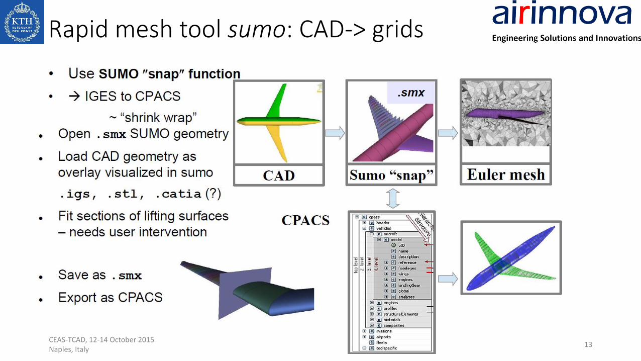
Rapid mesh tool sumo: CAD-> grids
13CEAS-TCAD, 12-14 October 2015Naples, Italy

Disciplinary Data Fusion ToolUtilize the DACE Toolbox
𝑓 𝑥∗ =
ℎ=1
𝑛
βℎ,𝑘𝑓(𝑥ℎ ) + ψ 𝑝𝑇𝚿−1 𝑓(𝑥) −
ℎ=1
𝑛
βℎ,𝑘𝑓(𝑥ℎ )
Mean value Linear regression weightings
ψ 𝑝(𝑥∗, 𝑥 𝑘 ) = exp(−
𝑘
θ𝑘|𝑥∗(𝑘) − 𝑥(𝑘)|𝑝𝑘)
𝚿 𝑖,𝑗 = ψ 𝑝(𝑥𝑖 , 𝑥𝑗)
CEAS-TCAD, 12-14 October 2015Naples, Italy
Kriging
Co-Kriging
Variable Fidelity
• Sampling• Fusion• Surrogate
modeling• Error tracking
Source 1
Aero-data from individual tools
1. text files
2. XML files
[data.Aero.Table, ...] Fused aero-data
Source 21. text files
2. XML files
[data.Aero.Table, ...]
SDSA table CPACS
3. Wing design methodology
• Aerodynamic wing design: historical trends
• Wing design procedure in industry
• Wing design approach: a procedure
• “mix” of 3 optimizer combinations • CEASIOM-OPT Matlab scripts
• SU2 black-box
• SCID inverse design
15CEAS-TCAD, 12-14 October 2015Naples, Italy

16
Aerodynamic wing design/optimization: Historic trends
1960 1970 1980 1990 2000 2010
Optimization /
MDO
transonicsJameson
FLO22
Euler
Equations
RANS
Turbulence
model
TSP; Full
potential
Virtual aircraft
Aerodynamics,
Structures, …
Linear
potential
Prandtl-Glauert
Fidelity
Software
Wind tunnel
Flight testFlight test
WT measure
Prediction
Reality
Prediction
WT measure
Fight test
CEAS-TCAD, 12-14 October 2015Naples, Italy

17
Sequential approach (break into sequence smaller steps).
Planform: given
1) Iterate
Determine thickness distribution:
● Min. Wave drag,
▪ maintaining wing box capacity
Determine camber & twist (combined):
● Min. Induced drag
▪ Check: ▪Span loading shape
▪ Root bending moment (RBM)
2) If winglet: optimize cant/fold angle, etc.
▪ reduce drag or improve RBM
3) Engineering know-how (applied at )
Swept isobars, span loading, thickness tapering,
Area ruling, tip wash, etc
Sequence of steps
Shape
Way it w
orks
Wing Design Approach: a procedure
User interaction
NOT an algorithm
Paper E
CEAS-TCAD, 12-14 October 2015Naples, Italy

Wing design optimization – 3 optimizer combinations
18
Engineer interaction • “baseline” shape• target C*p• geometry constraints,…
• Find geometry yielding target C*p
• Euler, RANS:
• Enables isobar “tailoring” at root and wing tip
• Use locally to improve pressure distribution• Maps shape to flow Cp
Engineer interaction limited to: • “baseline” shape• objective function• constraints,…
• Loosely coupled to flow solver, grid generator, etc• Parametric shape definition & re-meshing• Allows sequential treatment twist, thickness, camber,
etc• Flexible choice of objective function & constraints, …• Offers easy & plentiful Engineer interaction
Direct Optimization Minimize CD or L/D or …
INVERSE SOLVER
SCID
CEASIOM-OPT𝜕(∙)
𝜕𝒑𝒋SQP Matlab
Surface Curvature Inverse Design
User Interactive
Target Pressure
Editor
Geometry smoother/
Grid generator sumo
Working design Cp
Working design
Geometry
Target Cp*
sequential approach to shape opt
SU2All-in-box
Integrated design system
CEAS-TCAD, 12-14 October 2015Naples, Italy
• Tightly coupled - used as integrated closed system• Parameters determine shape perturbation & mesh
deformation• Shape defined by many parameters• Baseline mesh from CPACS/sumo• Built-in optimizer uses gradient from adjoint solution

4. Results and discussion of selected design studies
• Comparing 2 direction optimization methods: ONERA M6 wing
• Sequential optimization procedure: MOB blended wing body
• Inverse transonic wing design: joined wing configuration
• Propeller slipstream model Euler: Twin-prop 16 seater
• Control surfaces modelling in CEASIOM: Piaggio Avanti
• Flight motion analysis, data fusion: Transonic Trans-Cruiser
19CEAS-TCAD, 12-14 October 2015Naples, Italy

5. Conclusions• CEASIOM software improved
• Wing design toolbox: 2 direct opt methods, 1 inverse design• Loosely coupled direct optimization• Tightly coupled direct optimization• Inverse design
• Generalization of CEASIOM• airframe geometry modeling• Import function• CPACS dataset
• Demonstrated effectiveness on number of applications• Conventional as well as unconventional concepts
• BWB Inviscid drag is reduced around 45% at desired lift with fixed planform
• Transonic and low speed• Used to assess flying qualities
• Lessons learned• CEASIOM applied to the various design loops• Wing design is a procedure – therefore “cocktail mix” of opt methods is good strategy
• Engineer drive the process• Less tedious, better user interface, recommendation settings, …• Optimization with re-meshing technique robust
• Limitations of data fusion• Utilize DACE Toolbox, construct the meta-modelling procedures
• Optimization with re-meshing technique robust
CEAS-TCAD, 12-14 October 2015Naples, Italy

6. Future work • CEASIOM works better with CPACS
• Enhance CEASIOM capabilities in MDO • Better W&B module for flight simulation
• Better configuration modelling by adopting CPACS: CPACScreator
• Each individual module works with CPACS• CPACScreator CPACS
• Sumo CPACS
• Tornado CPACS (on progress)
• …
• Each individual module integrated into RCE
21CEAS-TCAD, 12-14 October 2015Naples, Italy