recent advances in the development and testing of hybrid ... · recent advances in the development...
TRANSCRIPT

RECENT ADVANCES IN THE DEVELOPMENT AND TESTING OF HYBRID PV-THERMAL COLLECTORS
Patrick Dupeyrat, Henning Helmers, Stefan Fortuin, Korbinian Kramer
Fraunhofer Institute for Solar Energy Systems ISE, Freiburg, Germany
Phone: +49 761 4588 5740, Fax:+49 761 4588 9000, E-Mail: [email protected]
1. Introduction
Hybrid photovoltaic and thermal (PVT) collectors combine photovoltaic (PV) cells and solar thermal components and enable the simultaneous conversion of solar energy into heat as well as into electricity. They provide potentially the most efficient conversion of solar radiation into useful energy. The combination of PV and Thermal for the co-generation of electricity and heat is not a new concept. Since the middle of the seventies, many regular journal articles have been published on this topic. In spite of the continuous interest in this concept, still no technological breakthroughs have been made to overcome the fact that with increasing temperature the electrical efficiency decreases. The best performance compromise caused by the combination of photovoltaic and thermal technologies is still to be found.
Many different configurations of PVT concepts have been investigated (different PV cell technologies, collector types, heat transfer media, heat removal constructions, system configurations, etc.). However, two main groups of PVT concepts can be identified: flat-plate PVT collectors (PVT) and concentrating PVT collectors (CPVT). Figure 1.1 shows a selection of different prototypes of PVT collectors: a non-covered flat-plate PVT air heating collector (a), a covered flat-plate PVT water heating collector (b), a CPVT collector with low concentration ratio using a trough concentrator (c) and a CPVT collector with high concentration ratio using a paraboloidal dish concentrator (d).
(a) (b) (c) (d)
Fig. 1.1: (a) Non-covered flat-plate PVT air collector (Joshi et al., 2009), (b) covered flat-plate PVT water collector (Fraunhofer ISE), (c) concentrating PVT collector with low concentration ratio using a trough concentrator (Coventry, 2005),
(d) concentrating PVT collector with high concentration ratio using a paraboloidal dish concentrator (Fraunhofer ISE).
Although the concept of PVT is not new, there is recent renewed interest in research and development in this field, not only regarding flat-plate PVT collectors but also regarding CPVT concepts.
Since PV and thermal components operate under conflicting conditions a straightforward integration of existing technologies has not resulted in a performance similar to separate PV and thermal performances. A fundamental analysis regarding materials, coatings, concepts and systems is currently undertaken for progress in this field. This includes accurate characterization of the components under various conditions, and determination of PV and thermal performance variations as a result of construction, material or geometric changes. Hence, appropriate and sufficiently accurate testing of the influence of these changes is required. In this paper, we present recent advances regarding both development and testing of flat-plate and concentrating PVT components at Fraunhofer ISE.

2. Development and testing of flat-plate PVT collectors
2.1. Development of flat-plate PVT collectors The focus of the first part of this paper is on the development and testing of a flat-plate PVT collector. Through broad numerical and experimental investigations on PV technologies (PV cell, module construction and materials) several prototypes of a covered flat-plate PVT collector were manufactured. In figure 2.1 the designs of two prototype PVT collectors are presented.
Thermal insulation (bottom)
Air layer
Thermal insulation (edge)
Glass cover
Thermal insulation (bottom)
Air layer
Thermal insulation (edge)
Glass cover Thin film module (CdTe)Crystalline silicon solar cell
Water channel(square shape)
Thermal glue
Solar cellGlass
Glass
PV-T absorber
PVT-A (c-Si) PVT-B (CdTe)
Water channel
Fig. 2.1: Cross sections of two covered flat-plate PVT water collectors. Left: (PVT-A) with laminated c-Si solar cells. Right:
(PVT-B) with CdTe thin film solar cells.
For the first collector (PVT-A), the PVT absorber was manufactured using an improved technique for the lamination of single-crystalline silicon solar cells on the top of an optimized flat heat exchanger (Dupeyrat et al., 2011). This PVT absorber was then encased in the frame of a solar collector. At the front, between the absorber plate and the high transmission glass cover (τ > 0.93), a static air layer with a thickness of 20 mm was set up to ensure good thermal insulation. The aperture area is Acol=1.01 m².
For the second collector (PVT-B), the PVT absorber was assembled connecting square copper channels mechanically and thermally on the back of a conventional thin film module (CdTe). CdTe modules have a lower efficiency than sc-Si modules, but their temperature dependency is much lower as well. The relative temperature coefficient of CdTe thin film is around -0.20 %/K, compared to -0.45 %/K for silicon cells. This PVT absorber was also encased in the frame of a solar collector. At the front, the static air layer has a thickness of 45 mm. The aperture area of the collector is Acol=1.55 m².
2.2. Testing of flat-plate PVT collectors: Test set-up In the second part of this chapter the performance evaluation of the developed PVT prototypes is presented. In spite of a recent and growing interest in the field of PVT, there is still no standardized test procedure for PVT collectors available.
Therefore, an appropriate test procedure to measure accurately both thermal and electrical performance was developed. The test procedure is based on the relevant standards for both solar thermal collectors (EN 12975-2) and for photovoltaic modules (IEC 61215). This paper only focuses on performance evaluation, collector durability is not subject of this work.
The performance measurements on the PVT collectors were carried out at the accredited test facility TestLab Solar Thermal Systems of Fraunhofer ISE, indoor test facilities. The thermal measurements on the developed PVT collector were carried out according to EN 12975. The collector was tilted with an angle of 45° and exposed to a constant average global irradiation in the solar simulator. This artificial sun is realized by a field of a 2 by 4 array of metal-halide lamps, each having a radiation output in a spectrum close to the AM1.5g spectrum.
In order to accurately account for losses from the collector to its surroundings, the simulator has an artificial sky and artificial wind, in accordance to EN 12975. The artificial sky is made of two highly transparent covers cooled by forced ventilated air, imitating the naturally cool sky. The artificial wind parallel to the collector simulates natural air convection (see figure 2.2).

Fig. 2.2: Schema of the test set-up at the indoor solar simulator. Parameters indicated in this figure are measured. Tamb,
ambient temperature; Tin and Tout, collector in- and outlet fluid temperature; Vwind, speed of the artificial airflow along the collector; G, solar radiation intensity; Tsky, artificial sky temperature; Pmpp, electrical power output.
In a first set of measurements, the PVT collectors are operated in open-circuit (oc) mode, i.e. the electric output of the PVT collector is not connected to an electrical load. Hence, there is no electric power output and the collector behaves like a normal ‘thermal only’ collector. In a second set of measurements, the PVT collector is connected to an electrical load in order to perform measurements of electrical and thermal performances in hybrid mode. The electrical output PPV is regulated by a maximum power point (MPP) tracker connected to an I-V scanner. This allows for measurements of the I-V characteristics under simulated operating conditions. The MPP tracker is connected with a four-wire system in order to not impact the fill factor.
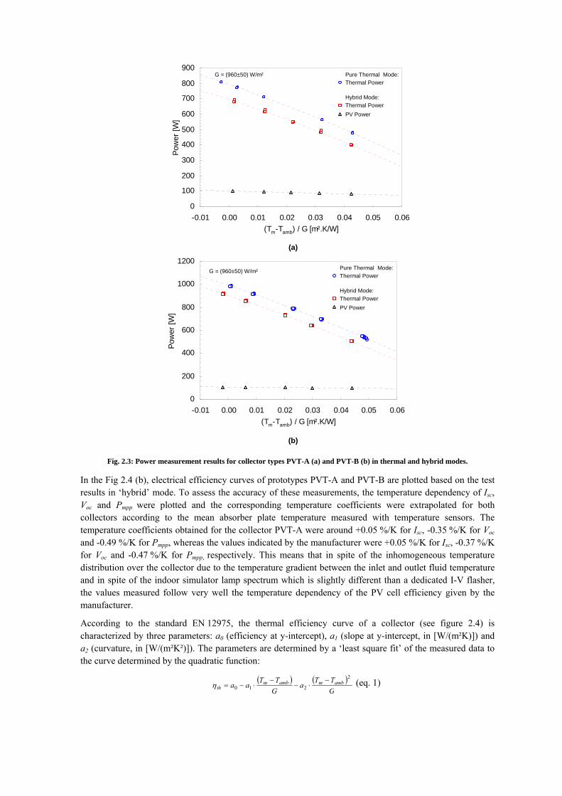
2.3. Testing of flat-plate PVT collectors: Performance evaluation in hybrid mode In figure 2.3 the measured thermal and photovoltaic power are plotted versus the reduced temperature for both collector types PVT-A (a) and PVT-B (b). The reduced temperature corresponds to the temperature difference between the fluid (Tm=(Tin+Tout)/2) and the ambient temperature (Tamb) divided by the global solar irradiance (G): (Tm-Tamb)/G.
For both collectors first, power measurements were carried out in open-circuit (oc) mode (‘thermal only’ mode) where no electrical power is extracted from the collector. Then, power measurements were carried out in maximum power point (‘hybrid’ mode) where the collector produces both thermal and electrical power.
In figure 2.4 (a), thermal efficiency curves of prototypes PVT-A and PVT-B are plotted based on the test results of both test sequences (‘thermal only’ mode and ‘hybrid’ mode).
The prototype is designed to replace a conventional thermal collector operating in a heating system. Therefore, the performance measured on the developed PV-T collector was compared to a benchmark thermal collector with a selectively coated absorber.
The thermal efficiency of the collector with selectively coated absorber at η0 was 0.82 whereas they were (in ‘thermal only’/’hybrid’ mode) 0.82/0.72 for the prototype PVT-A and 0.67/0.61 for the prototype PVT-B. This shows that the thermal efficiency η0 of the prototype PVT-A reached values almost as good as a conventional thermal collector. However, for both PVT collectors, the thermal losses (indicated by the downward slope) are still quite high.
0
200
400
600
800
1000
1200
-0.01 0.00 0.01 0.02 0.03 0.04 0.05 0.06(Tm-Tamb) / G [m².K/W]
Pow
er [W
]
PV PowerThermal Power
Thermal Power
Hybrid Mode:
Pure Thermal Mode:G = (960±50) W/m²
0
100
200
300
400
500
600
700
800
900
-0.01 0.00 0.01 0.02 0.03 0.04 0.05 0.06(Tm-Tamb) / G [m².K/W]
Pow
er [W
]
PV PowerThermal Power
Thermal Power
Hybrid Mode:
Pure Thermal Mode:G = (960±50) W/m²
(a)
(b) Fig. 2.3: Power measurement results for collector types PVT-A (a) and PVT-B (b) in thermal and hybrid modes.
In the Fig 2.4 (b), electrical efficiency curves of prototypes PVT-A and PVT-B are plotted based on the test results in ‘hybrid’ mode. To assess the accuracy of these measurements, the temperature dependency of Isc, Voc and Pmpp were plotted and the corresponding temperature coefficients were extrapolated for both collectors according to the mean absorber plate temperature measured with temperature sensors. The temperature coefficients obtained for the collector PVT-A were around +0.05 %/K for Isc, -0.35 %/K for Voc and -0.49 %/K for Pmpp, whereas the values indicated by the manufacturer were +0.05 %/K for Isc, -0.37 %/K for Voc and -0.47 %/K for Pmpp, respectively. This means that in spite of the inhomogeneous temperature distribution over the collector due to the temperature gradient between the inlet and outlet fluid temperature and in spite of the indoor simulator lamp spectrum which is slightly different than a dedicated I-V flasher, the values measured follow very well the temperature dependency of the PV cell efficiency given by the manufacturer.
According to the standard EN 12975, the thermal efficiency curve of a collector (see figure 2.4) is characterized by three parameters: a0 (efficiency at y-intercept), a1 (slope at y-intercept, in [W/(m²K)]) and a2 (curvature, in [W/(m²K²)]). The parameters are determined by a ‘least square fit’ of the measured data to the curve determined by the quadratic function:
( ) ( )GTT
aGTT
aa ambmambmth
2
210−
⋅−−
⋅−=η (eq. 1)

0%
10%
20%
30%
40%
50%
60%
70%
80%
90%
100%
0.00 0.01 0.02 0.03 0.04 0.05 0.06 0.07 0.08 0.09 0.10(Tm-Tamb) / G [m².K/W]
Ther
mal
Effi
cien
cy
0%1%2%3%4%5%6%7%8%9%
10%11%12%
0.00 0.01 0.02 0.03 0.04 0.05 0.06 0.07 0.08 0.09 0.10(Tm-Tamb) / G [m².K/W]
Elec
trica
l Effi
cien
cy
Pure Thermal Mode:PVT A (c-Si)
G = (960±50) W/m² Hybrid Mode:
PVT B (CdTe)
PVT A (c-Si)
G = (960±50) W/m² Hybrid Mode:
PVT B (CdTe)
(a)
(b)
PVT A (c-Si)
PVT B (CdTe)Thermal Collector
Fig. 2.4: Efficiency curves from PVT collector parameters based on the test results.
The curve fitting parameters obtained from the tests for each collector, in both ‘thermal only’ and ‘hybrid’ mode, are summarized in table 2.1.
Tab. 2.1: Curve fitting parameters for collectors PVT-A and PVT-B derived from the measured test results.
a0 a1 a2
Thermal collector 0.82 3.6 W/(m².K) 0.012 W/(m².K²) PVT-A in ‘thermal only’ mode (oc) 0.82 6.45 W/(m².K) 0.026 W/(m².K²) PVT-A in ‘hybrid’ mode (mpp) 0.67 5.52W/(m².K) 0.017 W/(m².K²) PVT-B in ‘thermal only’ mode (oc) 0.72 6.14 W/(m².K) 0.024 W/(m².K²) PVT-B in ‘hybrid’ mode (mpp) 0.61 5.46 W/(m².K) 0.015 W/(m².K²)

2.4. Testing of flat-plate PVT collectors: Summary The efficiency measurements of PVT collectors, involving the evaluation of both thermal and electrical performances, similar to testing of conventional solar components, are required for:
• An assessment of the collector’s performances in comparison with other PVT collectors as well as with other solar thermal collectors and with PV modules.
• As parameter input into computer models for the simulation of annual (thermal and electrical) system yields.
The ‘thermal only’ mode-tests allow for comparison of their performance with conventional ‘thermal only’ solar collectors as well as other PVT collectors in ‘thermal only’ mode. However, when electricity is generated less energy is available for thermal use, thus their thermal efficiency depends also on the electrical operation. It is foreseen that a PVT collector will be able to feed into the electricity grid whenever it receives incoming solar radiation, i.e. the collector will mostly operate in ‘hybrid’ mode. For annual thermal and electrical yield simulations ‘thermal only’ as well as ‘hybrid’ mode thermal efficiency tests (and curves) are required.
The efficiency of solar cells is temperature dependent. The temperature of PV cells which are part of a PVT collector depends partly on ambient conditions (i.e. solar irradiation, ambient temperature, wind), partly on the way the cells are integrated into the collector, and also depend on the operating mode of the collector (‘electrical only’ or ‘hybrid’ mode). The electrical performance of the PV cells thus depends on the operation of the thermal system in which the collector is integrated (e.g. domestic hot water system or combi-system for example) – whereas operation of a PV module only depends on its surroundings. However, for annual electrical and thermal yield simulations ‘thermal only’ as well as ‘hybrid’ mode efficiency tests (and curves) are sufficient (no ‘electrical only’ tests are needed) because the ‘electrical only’ operating point (i.e. temperature) is at the stagnation temperature in the ‘hybrid’ mode curve.
Measurement of ‘electrical only’ mode using a flash test under standard test conditions (i.e. 1000 W/m², AM1.5g, 25 °C cell temperature) to compare the PVT performance with conventional PV modules evaluated under the same standard test conditions is, from the fact that the PVT collector will practically never operate under these conditions, not relevant and even misleading. Therefore, the standard flash test is neither appropriate to make an assessment of the collector electrical performances nor to estimate the PVT electrical yield. In fact, the more appropriate way to compare the PV performances of PVT collectors is by comparing the simulated annual electrical yield of PVT collectors operating as part of the same thermal system in the same environmental situation. The thermal and electrical ‘hybrid’ mode efficiency curve (see Fig 2.4) of the PVT collector is sufficient for this.
The current test results show that the ‘thermal only’ and ‘hybrid’ mode method are accurate and that these modes characterize the performance of a PVT collector in a sufficiently realistic way. Current work focusses on further development of detailed collector models and their representation in simulation software, as this will make visible how effective the PVT collectors potentially are in comparison to ‘thermal only’ as well as ‘electrical only’ collectors.
There is also more work needed on PVT specific testing procedures addressing their durability (Hoffman et al., 2010).
3. Development and testing of concentrating PVT collectors
In the second part of this paper, the focus is on development and testing of concentrating PVT collectors. In a CPVT collector the receiver is illuminated by highly concentrated solar irradiation, focused by appropriate optics. As for non-concentrating PVT collectors, so far there is no standardized measurement routine for CPVT collectors available.
3.1. Development of CPVT receivers As CPVT receivers operate under highly concentrated sun light (>200 times), one main challenge for the design of an appropriate CPVT receiver is to remove a comparably large quantity of heat from a small area. At the same time the solar cell operating temperature should be as small as possible, i.e. the thermal resistance (Rth) between heat transfer fluid and solar cell has to be low. Additionally, the solar cells in use need to operate under high concentration ratios, i.e. special concentrator solar cells are used. Furthermore, the receiver is located in front of the concentrator and shades the optics. Therefore, the packaging density, i.e. the ratio of active photovoltaic area to total area, should be high.
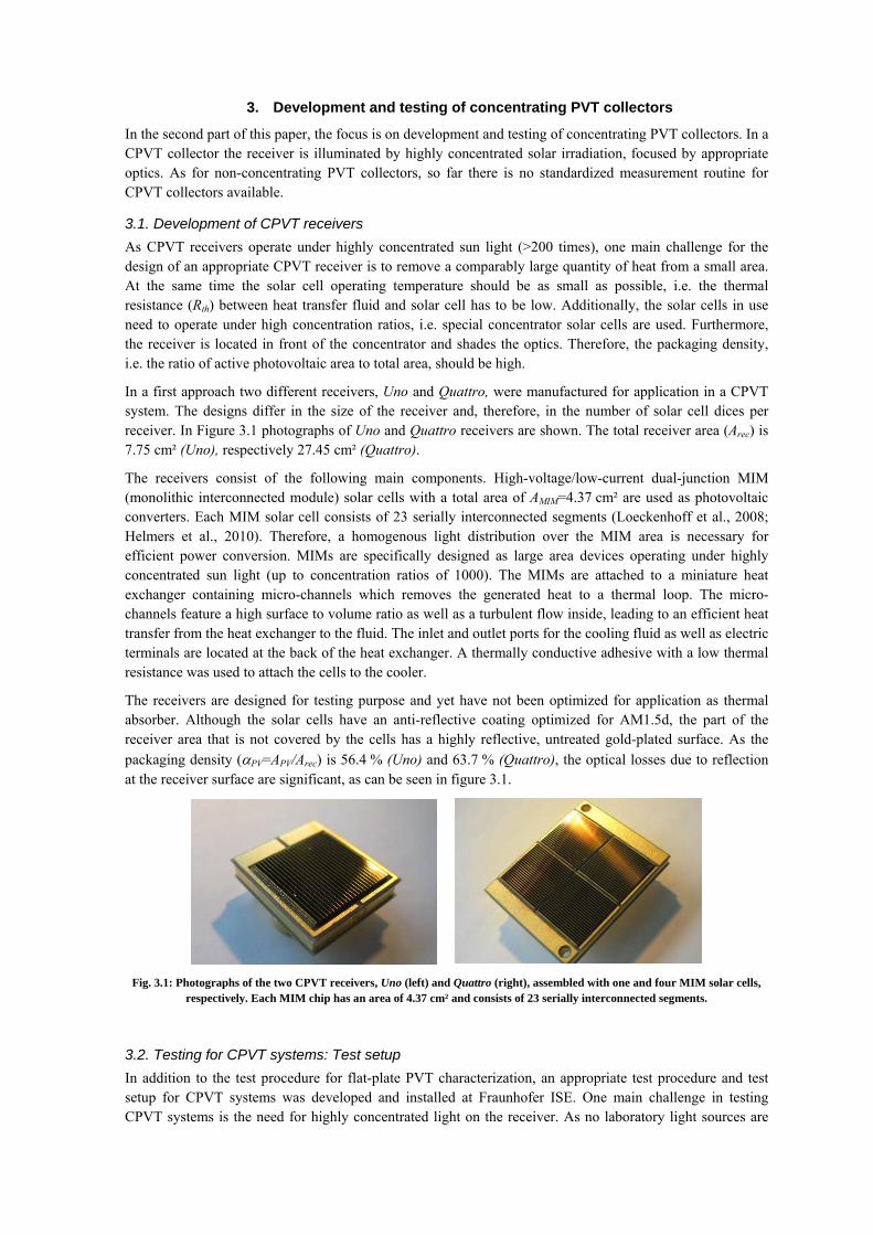
In a first approach two different receivers, Uno and Quattro, were manufactured for application in a CPVT system. The designs differ in the size of the receiver and, therefore, in the number of solar cell dices per receiver. In Figure 3.1 photographs of Uno and Quattro receivers are shown. The total receiver area (Arec) is 7.75 cm² (Uno), respectively 27.45 cm² (Quattro).
The receivers consist of the following main components. High-voltage/low-current dual-junction MIM (monolithic interconnected module) solar cells with a total area of AMIM=4.37 cm² are used as photovoltaic converters. Each MIM solar cell consists of 23 serially interconnected segments (Loeckenhoff et al., 2008; Helmers et al., 2010). Therefore, a homogenous light distribution over the MIM area is necessary for efficient power conversion. MIMs are specifically designed as large area devices operating under highly concentrated sun light (up to concentration ratios of 1000). The MIMs are attached to a miniature heat exchanger containing micro-channels which removes the generated heat to a thermal loop. The micro-channels feature a high surface to volume ratio as well as a turbulent flow inside, leading to an efficient heat transfer from the heat exchanger to the fluid. The inlet and outlet ports for the cooling fluid as well as electric terminals are located at the back of the heat exchanger. A thermally conductive adhesive with a low thermal resistance was used to attach the cells to the cooler.
The receivers are designed for testing purpose and yet have not been optimized for application as thermal absorber. Although the solar cells have an anti-reflective coating optimized for AM1.5d, the part of the receiver area that is not covered by the cells has a highly reflective, untreated gold-plated surface. As the packaging density (αPV=APV/Arec) is 56.4 % (Uno) and 63.7 % (Quattro), the optical losses due to reflection at the receiver surface are significant, as can be seen in figure 3.1.
Fig. 3.1: Photographs of the two CPVT receivers, Uno (left) and Quattro (right), assembled with one and four MIM solar cells,
respectively. Each MIM chip has an area of 4.37 cm² and consists of 23 serially interconnected segments.
3.2. Testing for CPVT systems: Test setup In addition to the test procedure for flat-plate PVT characterization, an appropriate test procedure and test setup for CPVT systems was developed and installed at Fraunhofer ISE. One main challenge in testing CPVT systems is the need for highly concentrated light on the receiver. As no laboratory light sources are

available that generate these high intensities, the developed test setup operates outdoors and uses an optical concentrator that focuses direct sunlight onto the receiver under test.
In the presented setup a paraboloidal solar mirror with a diameter (d) of 1.17 m is mounted on a two-axis tracking unit (see figure 1d) which follows the sun’s position over the day. The CPVT receiver is mounted on a three-axis positioning arm, enabling variable positioning on the optical axis as well as motorized scanning of the focal plane. Due to manipulation of the position of the receiver on the optical axis around the focal distance of the concentrator the size of the focal spot and the irradiated intensity onto the receiver area is adjustable. E.g. at 35 mm behind the focal distance of the mirror the focal spot expands to a diameter of about 7 cm (see also figure 3.3). Taking shading into account the effective aperture area (Aap) is 1.035 m².
Tout
Tin CPVT Receiver
Process Thermostat
Electr. Load
PC
Tamb
GDNI
vWind
GGNI
Ambient Conditions
Fig. 3.2: Schematic drawing of the main measurement equipment used for characterization of CPVT systems.
The procedure for characterization of the thermal performance of the CPVT collector follows a stationary approach based on EN 12975-2. Figure 3.2 shows a schematic drawing of the measurement equipment. The inlet temperature of the cooling fluid at the receiver is controlled by a process thermostat. The mass flow is regulated by a control valve and measured using a magnetic inductive flow meter. Inlet and outlet temperatures (Tin and Tout) are measured using calibrated Pt100 resistance thermometers. The closed thermal cycle can operate at a maximum pressure of 6 barabs. Hence, at temperatures above 100 °C water can still be used as cooling fluid. The maximum inlet temperature is 120 °C.
For characterization of the electrical performance, the CPVT receiver is connected with an electronic load through a four-wire system. Current-voltage characteristics and the photovoltaic parameters (short-circuit current Isc, open-circuit voltage Voc, fill factor FF, and maximum power Pmpp) can then be measured. For the characterization of ‘thermal only’ mode the photovoltaic module is held at open-circuit condition. In order to characterize the hybrid performance, a MPP tracking algorithm is integrated in the electronic load.
Furthermore, direct (beam) and global normal irradiation, wind speed and ambient temperature are measured during the tests.
3.3. Testing of CPVT collectors: Performance evaluation in hybrid mode The characterization of the operating performance of a CPVT collector follows in principle the routine described above for PVT collectors. However, the concentrating optics of the two-axis tracking system only focuses the incident radiation parallel to the optical axis, i.e. the direct (‘beam’) normal irradiance Gb. Hence, the reduced temperature difference for a concentrating system is defined by the difference between mean fluid and ambient temperatures divided by the direct normal irradiance (Gb) only: (Tm-Tamb)/Gb.
The thermal and photovoltaic conversion efficiencies of the system (ηth,System and ηPV,System) are defined by the output power (Pth and PPV, respectively) divided by the incident radiated power on the aperture area (Pin,ap=Aap·Gb), thus: ηth/PV,System=Pth/PV/Pin,ap. However, with changes in the receiver position around the focal distance (f) of the concentrator, the incident radiated power onto the receiver surface (Pin,rec) varies. This means there is an inhomogeneous light distribution in the focal plane and spilled light does not meet the receiver. As a result these spillage losses have to be taken into account for a system assessment of a complete CPVT system. However, if the aim of the characterization is the investigation of the receiver performance under different conditions these spillage losses should not be included when determining receiver efficiency.

This is done using only the incident radiated power onto the receiver area (Pin,rec) for normalizing the power outputs: ηth/PV =Pth/PV/Pin,rec.
In order to characterize different focal planes around the focal distance, the focal spot was scanned in x- and y-direction with a test module consisting of only one solar cell with an area of APV=1.1 cm². Normalizing the measured short-circuit currents Isc(x,y) with the short-circuit measured in the laboratory at one sun standard test conditions (STC; 1000 W/m², AM1.5d, 25 °C) leads to a map of the concentration ratio C(x,y)=Isc(x,y)/Isc(STC) over the investigated focal plane. Figure 3.3 shows the concentration map in the focal plane at z=f+35 mm.1
Fig. 3.3: Map of the concentration ratio C(x,y)=Isc(x,y)/Isc(STC) in the focal plane z=f+35 mm. Closer to the focal point, the
focal spot becomes smaller and the concentration ratio increases.
The Uno CPVT receiver was characterized while operating in ‘hybrid’ mode with maximum (electric) power point tracking. Due to the series connection of the segments the MIM solar cell is sensitive to inhomogeneous illumination. Therefore, the measurement was performed at a position on the optical axis of z=f+35 mm (i.e. 35 mm behind the focal point), where the concentration ratio over the MIM solar cell is C=267±7 (see figure 3.3) and, thus, sufficiently homogenous. However, in this position a significant part of the concentrated radiation does not hit the MIM solar cell with an edge length of 20.9 mm. In order to derive the respective thermal and electric efficiencies for the receiver, the measured thermal and electric power outputs were divided by the incident radiated power onto the receiver area, where for simplicity homogeneous illumination with C=267 is assumed: Pin=C.Arec.Gb.
In figure 3.4 the thermal and electric efficiencies are plotted versus the reduced temperature difference. The values A ‘least squares fit’ to the function determined by equation 1 resulted in the parameters listed in table 3.1. Because of the small receiver area, the thermal losses are lower than for non-concentrating PVT. The higher the concentration ratios the more significant this effect will be.
The photovoltaic efficiency is fitted linearly. The relative (reduced) temperature coefficient is: (∂ηPV/∂T*).Gb/ηPV(T*=0) = -0.077 %/K. The temperature coefficient is significantly lower than for non-concentrating systems. This is expected because (i) multi-junction concentrator solar cells feature low temperature coefficients because of the material properties of the III-V semiconductors they are made of, and (ii) the temperature coefficient of Pmpp (i.e. ηPV) decreases with increasing concentration.
Further, the measured ambient conditions and system parameters were fed into a theoretical model for CPVT systems [Helmers et al., 2011]. As can be seen in figure 3.4, the simulated efficiencies (simu: cross/plus) agree very well with the fitted experimental data (dashed lines).
1 The deviation of the shape from the expected circular symmetry is not part of this paper and will be described elsewhere.
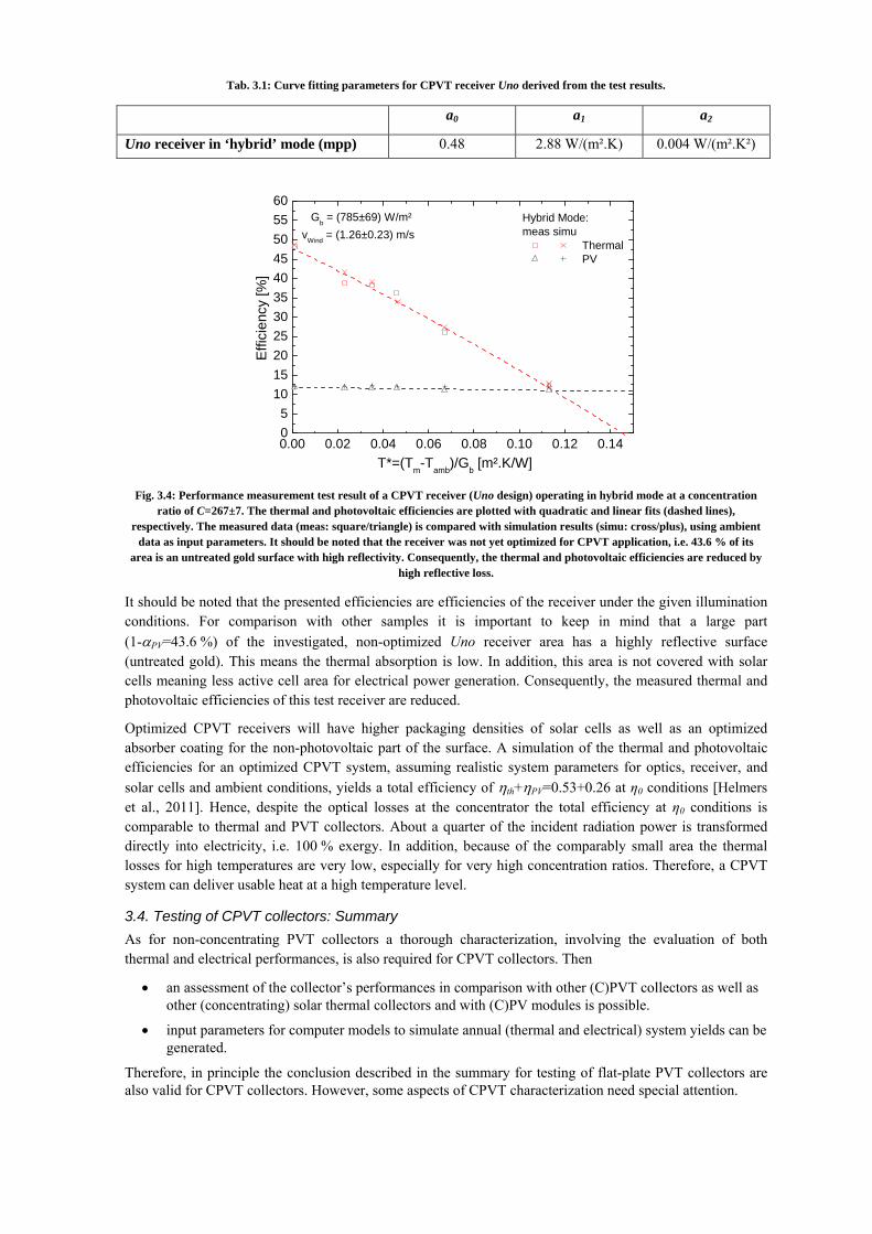
Tab. 3.1: Curve fitting parameters for CPVT receiver Uno derived from the test results.
a0 a1 a2
Uno receiver in ‘hybrid’ mode (mpp) 0.48 2.88 W/(m².K) 0.004 W/(m².K²)
0.00 0.02 0.04 0.06 0.08 0.10 0.12 0.1405
1015202530354045505560
Gb = (785±69) W/m²vWind = (1.26±0.23) m/s
Hybrid Mode:meas simu
Thermal PV
Effi
cien
cy [%
]
T*=(Tm-Tamb)/Gb [m².K/W] Fig. 3.4: Performance measurement test result of a CPVT receiver (Uno design) operating in hybrid mode at a concentration
ratio of C=267±7. The thermal and photovoltaic efficiencies are plotted with quadratic and linear fits (dashed lines), respectively. The measured data (meas: square/triangle) is compared with simulation results (simu: cross/plus), using ambient
data as input parameters. It should be noted that the receiver was not yet optimized for CPVT application, i.e. 43.6 % of its area is an untreated gold surface with high reflectivity. Consequently, the thermal and photovoltaic efficiencies are reduced by
high reflective loss.
It should be noted that the presented efficiencies are efficiencies of the receiver under the given illumination conditions. For comparison with other samples it is important to keep in mind that a large part (1-αPV=43.6 %) of the investigated, non-optimized Uno receiver area has a highly reflective surface (untreated gold). This means the thermal absorption is low. In addition, this area is not covered with solar cells meaning less active cell area for electrical power generation. Consequently, the measured thermal and photovoltaic efficiencies of this test receiver are reduced.
Optimized CPVT receivers will have higher packaging densities of solar cells as well as an optimized absorber coating for the non-photovoltaic part of the surface. A simulation of the thermal and photovoltaic efficiencies for an optimized CPVT system, assuming realistic system parameters for optics, receiver, and solar cells and ambient conditions, yields a total efficiency of ηth+ηPV=0.53+0.26 at η0 conditions [Helmers et al., 2011]. Hence, despite the optical losses at the concentrator the total efficiency at η0 conditions is comparable to thermal and PVT collectors. About a quarter of the incident radiation power is transformed directly into electricity, i.e. 100 % exergy. In addition, because of the comparably small area the thermal losses for high temperatures are very low, especially for very high concentration ratios. Therefore, a CPVT system can deliver usable heat at a high temperature level.
3.4. Testing of CPVT collectors: Summary As for non-concentrating PVT collectors a thorough characterization, involving the evaluation of both thermal and electrical performances, is also required for CPVT collectors. Then
• an assessment of the collector’s performances in comparison with other (C)PVT collectors as well as other (concentrating) solar thermal collectors and with (C)PV modules is possible.
• input parameters for computer models to simulate annual (thermal and electrical) system yields can be generated.
Therefore, in principle the conclusion described in the summary for testing of flat-plate PVT collectors are also valid for CPVT collectors. However, some aspects of CPVT characterization need special attention.

The need for high irradiation intensities requires the application of an appropriate concentrator as simulator light sources are not capable of delivering sufficient power densities to achieve steady operation conditions. This necessity leads to the requirement for outdoor characterization. Therefore, the main external parameters of a measurement, namely the direct normal irradiance, wind speed, and ambient temperature, cannot be kept arbitrarily constant.
Another effect of the application of a concentrator is that the shape of the focal spot has great influence on the performance (especially for series-connected photovoltaic cells) of the CPVT receiver. Hence, for a thorough evaluation of the performance, sufficient knowledge of the flux profile (i.e. the shape and illumination profile of the focal spot) at measurement conditions (meaning the focal plane where the receiver is located) is important. If the flux profile is not known it can be helpful to have results of laboratory measurements under standard test conditions, mainly the short-circuit current. Then the concentration ratio can be estimated by comparing the outdoor measurement at 25 °C to the laboratory measurements. However, it should be noted that besides temperature also other effects have an influence on the operating performance, in particular the influence of the spectrum should not be neglected especially for multi-junction solar cells.
To compare results from different CPVT receivers measured at various conditions, it is crucial to have a clear definition of the efficiency, i.e. the incident radiated power that is used for normalizing the power outputs: Without having sufficient information on the incident flux profile at the receiver surface, no meaningful efficiency value can be determined. This is also the case for comparisons using simulation models.
Furthermore, the safety requirements for the cooling cycle should be mentioned. Contrary to flat-plate PVT collectors, a CPVT collector without circulating heat transfer fluid will soon overheat and possibly become permanently damaged.
The presented test results in ‘hybrid’ mode fit very well with theoretically modeled data. One focus of current research lies on an extension of the CPVT model and continuous validation in order to enable yield estimations for a complete CPVT system depending on both, the applied optics and receiver parameters as well as location and ambient conditions. Further work also focuses on testing and optimization of different CPVT receiver designs.
4. Conclusion
The requirements for accurate and repeatable measurements when researching new materials, technologies and concepts for flat-plate PVT collectors as well as concentrating PVT collectors are high. Accurate characterization tests are also required for direct comparison of performance and for computer simulated yield estimations.
Flat-plate PVT collectors require ‘thermal only’ as well as ‘hybrid’ mode tests and performance curves. ‘Electrical only’ measurements do not make sense, as for PVT collectors the electrical performance depends on the thermal performance of the collector. In this case the ‘hybrid’ mode tests are sufficient. Separate PV flash tests under standard conditions for PV modules are not relevant and can even be misleading as the collector will never operate in practice under these conditions.
In principle, the characterization of CPVT collectors does not differ essentially from PVT performance evaluation. Here too the main interest is the evaluation of the performance in ‘hybrid’ mode. Additionally special attention has to be paid to the applied concentrating optics. Measurements and knowledge of the incident irradiated power onto the receiver is particularly important in order to define an efficiency value that allows for meaningful comparison of different CPVT receivers operating in different systems under different conditions.
The work at Fraunhofer ISE regarding both PVT and CPVT contributes to the development of standardized test routines, together with experts from the solar thermal and PV branches. The goal is to ultimately come to broadly accepted performance test standards for both PVT and CPVT collectors.
5. Acknowledgments
The authors would like to give special thanks to Alexander Boos, Felix Jetter, Jens Richter and Christophe Thoma for their support. H. Helmers gratefully acknowledges the scholarship support of the German Federal
Environmental Foundation (DBU). This work was partly funded by the Federal Ministry for the Environment, Nature Conservation and Nuclear Safety (BMU) under the “KoMGen” project (#0327567A). The authors are responsible for the content of this paper.
6. References
Coventry, J.S. 2005. Performance of a concentrating photovoltaic/thermal solar collector. Sol. Energy 78(2), 211-222.
Dupeyrat, P., Ménézo, C., Rommel, M., Henning, H-M., 2011, Efficient single glazed flat plate photovoltaic–thermal hybrid collector for domestic hot water system, Solar Energy, 85, 1457-1468.
Helmers, H., Oliva, E., Bronner, W., Dimroth, F., Bett, A.W., 2010. Processing Techniques for Monolithic Interconnection of Solar Cells at Wafer Level. IEEE Trans. Electron Devices 57(12), 3355-3360.
Helmers, H., Boos, A., Jetter, F., Heimsath, A., Wiesenfarth, M., Bett, A.W., 2011. Outdoor Test Setup for Concentrating Photovoltaic and Thermal (CPVT) Systems. AIP Conf. Proc. 7th Int. Conf. on Concentrating Photovoltaic Systems (CPV-7), Las Vegas, USA.
Hofmann, P., Dupeyrat, P., Kramer, K., Hermann, M., and Stryi-Hipp, G., 2010. Measurements and Benchmark of PV-T collectors according to EN12975 and development of a standardized measurement procedure ; In Proceedings, EuroSun 2010, 28.9-1.10.2010, Graz, Austria.
Joshi, A.S., Tiwari, A., Tiwari, G.N., Dincer, I., Reddy, B.V., 2009. Performance evaluation of a hybrid photovoltaic thermal (PV/T) (glass-to-glass) system. Int. J. Therm. Sci. 48(1), 154-164.
Loeckenhoff, R., Dimroth, F., Oliva, E., Ohm, A., Wilde, J., Faiman, D., Biryukov, S., Melnichak, V., Kabalo, S., Bokobza, D., Bett, A.W., 2008. Development, Characterisation and 1000 Suns Outdoor Tests of GaAs Monolithic Interconnected Module (MIM) Receivers. Prog. Photovoltaics Res. Appl. 16(2), 101-112.