receiving and inspection warning!!
TRANSCRIPT

AX0020123
July 2013 Rev. 2
Recirculating Hood
Installation, Operation, and Maintenance Manual
Save these instructions. This document is the property of the owner of this equipment and is required for future maintenance. Leave this document with the owner when installation or service is complete.
RECEIVING AND INSPECTION Upon receiving unit, check for any interior and exterior damage, and if found, report it immediately to the carrier. Also check that all accessory items are accounted for and are
damage free.
WARNING!!
Installation of this unit should only be performed by a qualified professional who has read and understands these instructions and is familiar with proper safety precautions. Read this
manual thoroughly before installing or servicing this equipment.

2
TABLE OF CONTENTS WARRANTY .................................................................................................................................................. 4 LISTINGS ...................................................................................................................................................... 4 INSTALLATION ............................................................................................................................................. 5
Site Preparation ........................................................................................................................................ 5 Mechanical Installation ............................................................................................................................. 5
Plumbing Connections for CORE Total Flood Protection .................................................................... 7 Table 1 – Clearances ........................................................................................................................... 8 Hanging Dimensions ............................................................................................................................ 8 Hanging Details .................................................................................................................................... 9 Copper Wire Ampacity ....................................................................................................................... 10 Electrical Connections ........................................................................................................................ 10 Wiring Distance Limitations ................................................................................................................ 11 Fire Alarm Contacts ............................................................................................................................ 11
OPERATION ............................................................................................................................................... 12 Start Up Procedure ................................................................................................................................. 12 Components............................................................................................................................................ 12 Hood Switch Plate .................................................................................................................................. 12 CORE Protection Fire System Printed circuit board ............................................................................... 13 CORE Protection Fire System ................................................................................................................ 16 CORE Protection Reset Overview .......................................................................................................... 16 CORE Total Flood Coverage .................................................................................................................. 17
Hazard Zone and Nozzle Placement.................................................................................................. 17 CORE Total Flood Protection Fire System Start Up............................................................................... 17
Special Tools Required ...................................................................................................................... 17 Reset Procedure – CORE Protection Fire System ............................................................................ 19
Start Up Checklists ................................................................................................................................. 20 Hood Start Up Checklist ..................................................................................................................... 20 CORE Protection System Start Up Checklist ..................................................................................... 20 CORE Protection System Reset Checklist ......................................................................................... 20 RH-2 CORE Component Overview .................................................................................................... 21 RH-2 CORE Spray Bar Component Details ....................................................................................... 22 CORE Protection Pull Station ............................................................................................................. 23 CORE Protection Firestat ................................................................................................................... 24 CORE Protection Waterline Supervision ............................................................................................ 25 Battery Backup ................................................................................................................................... 26 Electrical Board .................................................................................................................................. 27 Filters .................................................................................................................................................. 29 Filter Stages ....................................................................................................................................... 29 Filter Part Numbers ............................................................................................................................ 30
Troubleshooting ...................................................................................................................................... 31 Troubleshooting Chart ........................................................................................................................ 31 CORE Protection Fire System Troubleshooting Chart ....................................................................... 32
MAINTENANCE .......................................................................................................................................... 33 Every 6 months ....................................................................................................................................... 34 Every 2 Years ......................................................................................................................................... 34 After A Fire .............................................................................................................................................. 34
Start-Up and Maintenance Documentation ................................................................................................. 35 Job Information ................................................................................................................................... 35 Hood Information ................................................................................................................................ 35 Maintenance Record .......................................................................................................................... 36 Factory Service Department ............................................................................................................... 36

3

4
WARRANTY This equipment is warranted to be free from defects in materials and workmanship, under normal use and service, for a period of 12 months from date of shipment. This warranty shall not apply if:
1. The equipment is not installed by a qualified installer per the MANUFACTURER’S installation instructions shipped with the product,
2. The equipment is not installed in accordance with federal, state and local codes and regulations, 3. The equipment is misused or neglected, 4. The equipment is not operated within its published capacity, 5. The invoice is not paid within the terms of the sales agreement.
The MANUFACTURER shall not be liable for incidental and consequential losses and damages potentially attributable to malfunctioning equipment. Should any part of the equipment prove to be defective in material or workmanship within the 12-month warranty period, upon examination by the MANUFACTURER, such part will be repaired or replaced by MANUFACTURER at no charge. The BUYER shall pay all labor costs incurred in connection with such repair or replacement. Equipment shall not be returned without MANUFACTURER’S prior authorization, and all returned equipment shall be shipped by the BUYER; freight prepaid to a destination determined by the MANUFACTURER.
LISTINGS
This hood is ETL listed to standard UL-710B and EPA test method 202 when installed in accordance with these installation instructions and National Fire Protection Association Standard “NFPA 96, Standard for Ventilation Control and Fire Protection of Commercial Cooking Operations.”
5
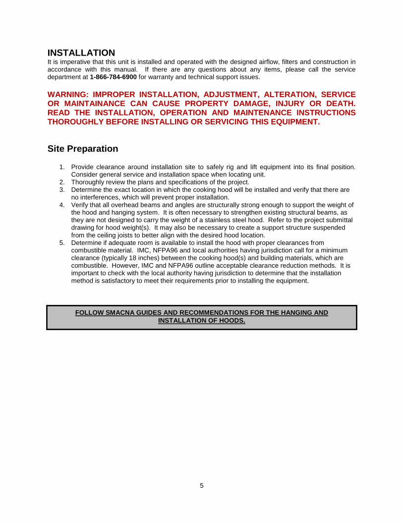
INSTALLATION It is imperative that this unit is installed and operated with the designed airflow, filters and construction in accordance with this manual. If there are any questions about any items, please call the service department at 1-866-784-6900 for warranty and technical support issues.
WARNING: IMPROPER INSTALLATION, ADJUSTMENT, ALTERATION, SERVICE OR MAINTAINANCE CAN CAUSE PROPERTY DAMAGE, INJURY OR DEATH. READ THE INSTALLATION, OPERATION AND MAINTENANCE INSTRUCTIONS THOROUGHLY BEFORE INSTALLING OR SERVICING THIS EQUIPMENT.
Site Preparation
1. Provide clearance around installation site to safely rig and lift equipment into its final position. Consider general service and installation space when locating unit.
2. Thoroughly review the plans and specifications of the project. 3. Determine the exact location in which the cooking hood will be installed and verify that there are
no interferences, which will prevent proper installation. 4. Verify that all overhead beams and angles are structurally strong enough to support the weight of
the hood and hanging system. It is often necessary to strengthen existing structural beams, as they are not designed to carry the weight of a stainless steel hood. Refer to the project submittal drawing for hood weight(s). It may also be necessary to create a support structure suspended from the ceiling joists to better align with the desired hood location.
5. Determine if adequate room is available to install the hood with proper clearances from combustible material. IMC, NFPA96 and local authorities having jurisdiction call for a minimum clearance (typically 18 inches) between the cooking hood(s) and building materials, which are combustible. However, IMC and NFPA96 outline acceptable clearance reduction methods. It is important to check with the local authority having jurisdiction to determine that the installation method is satisfactory to meet their requirements prior to installing the equipment.
FOLLOW SMACNA GUIDES AND RECOMMENDATIONS FOR THE HANGING AND
INSTALLATION OF HOODS.

6
Mechanical Installation
Step-by-step procedure for installation of the Recirculating Hood
1. Uncrate the hood, being very careful not to dent or scratch the outer surface. NOTE: Report any damage to the delivering freight carrier and file a claim if appropriate. Refer to the installation drawing for typical details of the ventilation system prior to hanging the hood. Check the nameplate on the equipment to make certain it meets the specifications provided by the architect and/or engineer. If discrepancies exist, notify the manufacturer immediately.
2. It’s important that you have read and understand “Site Preparation” before continuing with the installation of the hood. See Table 1 “Clearances.”
3. If being hung from above, determine the exact location of the hood. Ensure support beams are structurally strong enough to support the weight of the hood. The structural integrity of the structural support system is the responsibility of the contractor and the structural engineer
4. Use 1/2-16 threaded rod to hang the hood. Drill 5/8” holes in the structural support system or use Unistrut® to line up with the holes on the hood’s corner hanging angles. See Figure 1 for details.
5. Each corner of the hood has a pre-punched hanging angle. It is important that the 1/2-16 threaded rod that will be used to suspend the hood is secured at these locations.
6. Raise the hood into position using high lifts or equipment jacks at each end of the hood to ensure the hood is level. When the hood is elevated to the proper height, install 1/2-16 threaded rod between the hood hanging angles and the modified supports in the ceiling. Secure the threaded rod with nuts and appropriate sized fender washers above and below hanging angles.
7. Make final adjustments as needed to ensure that the hood is level. Maintain tension on all the rods to ensure hood weight is evenly distributed. Make fine adjustments to the height of the hood by simply moving the hardware up and down the threaded rod.
8. For further information detailing installation and dimensional data. See Figure 1, 1A & 1B.

7
Plumbing Connections for CORE Total Flood Protection
WARNING: APPLY THE APPROPRIATE WATER PRESSURE AND TEMPERATURE TO ALL FITTINGS TO PREVENT LEAKAGE AND COMPONENT FAILURE ATTENTION: SYSTEM MUST BE INSTALLED IN CONDITIONED SPACE BETWEEN 32°F AND 130°F Ensure there is 36 Inches of service clearance to the front of the Controls Cabinet. Field plumbing connections are required for proper CORE Total Flood Protection fire system operation. It is recommended that all plumbing connections be sealed with Teflon tape or pipe dope. Use care not to contaminate the interior surfaces of the water lines when plumbing the unit, as small particulate can clog the orifices of the spray nozzles.
1. All incoming plumbing connections are connected via minimum ¾” quick seal above the utility cabinet.
2. A supervised water supply must be connected to the CORE connection. This requires a water connection at 30 to 70 PSI operating pressure. Water pressure may not drop below 30 PSI while the fire system is operating. Pressure may not rise above 70 PSI when the fire system is operating. If the operating pressure is greater than 70 PSI, a water regulator must be connected. Max water static pressure is 125 PSI. Typical water flow rate is 1.5 GPM per foot of hood. The water connection must be minimum ¾” pipe. This must be connected to a water supply line immediately downstream from the building main shut-off valve or a fire sprinkler system. This main valve must be continuously supervised. If other appliances are connected to the CORE water supply line, those appliances must be operated during the CORE system testing, and taken into consideration when calculating the size of the waterline pipe.
Warning All drain lines, field connections between hoods, and incoming CORE Protection lines must be run with Steel, Stainless Steel, or Copper pipe. Plastic pipe cannot be used for drains, field connections between
hoods, or CORE Protection supply lines as it could fail and become hazardous.
IMPORTANT!! CORE Protection water connection requires a supervised supply line. This must be connected
immediately downstream from the building main shut-off valve or building sprinkler system. A minimum
water operating pressure of 30 psi (while the fire system is operating) must be achieved at the hood.

8
Table 1 – Clearances
Equipment Type Clearances
Ovens
X" maximum from hood skirt bottom to door top.
X" minimum from hood skirt bottom to oven top.
X" minimum hood skirt over hang to heated oven door.
Conveyor Ovens
X" maximum from hood skirt bottom to top of conveyor belt.
X" minimum from hood skirt bottom to oven top.
X" minimum hood skirt over hang to heated oven door.
Rotisseries
X" maximum from hood skirt bottom to door top.
X" minimum from hood skirt bottom to oven top.
X" minimum hood skirt over hang to heated oven door.
Hanging Dimensions
Figure 1

9
Figure 1A
Hanging Details
Figure 1B

10
Copper Wire Ampacity
Wire Size AWG Maximum Amps
14 15
12 20
10 30
8 50
6 65
4 85
Electrical Before connecting power to the hood, read and understand the entire section of this document. As-built wiring diagrams are furnished with each hood by the factory and are attached to the inside of Controls access door of the hood. Electrical wiring and connections should be done in accordance with local ordinances and the National Electric Code, ANSI/NFPA70. Be sure the voltage and phase of the power supply and the wire amperage capacity is in accordance with the unit nameplate.
Electrical Connections
1. Always disconnect power before working on or near this hood. Lock and tag the disconnect switch or breaker to prevent accidental power up.
2. (4) 7/8” knockouts have been provided in the top of the hood so conduit and/or electrical drops can be connected to an appropriate power source.
3. Make certain that the power source is compatible with the requirements of your hood. The hood wiring schematic identifies the proper phase and voltage of the hood and appliances.
4. Interlocks between the electrical appliance and the hood are provided. Interlocks will be identified on the as built wiring diagram; failure to use interlocks will void hood listing.
5. Before connecting hood to power source, verify power line wiring is de-energized. 6. Secure the power cables to prevent contact with sharp objects. 7. Do not kink power cable and never allow the cable to come in contact with oil, grease, hot
surfaces or chemicals. 8. Before powering up the hood make sure that the interior of the hood is free of loose debris or
shipping materials and that all wire connections have been inspected. 9. There are multiple electrical connections required for this control. 120VAC should be wired to
terminals H1 and N1. H1 and N1 should not be connected to a shunt trip breaker. Incoming Appliance power should be wired as shown in wiring schematic included with hood to L1, L2 & L3 for Contactors 1& 2.
10. Make certain that the power source is compatible with the requirements of your equipment. The system wiring schematic identifies the proper phase and voltage of the equipment.
11. Before connecting control to power source, verify power line wiring is de-energized. 12. Secure the power cable to prevent contact with sharp objects. 13. Do not kink power cable and never allow the cable to come in contact with oil, grease, hot
surfaces or chemicals. 14. Before powering up the system, make sure that the interior of the control is free of loose debris or
shipping materials. 15. If any of the original internal wire supplied with the system must be replaced, it must be replaced
with type THHN wire or equivalent. 16. All field supplied wire for the optional CORE Protection fire system solenoid or Firestat must be
high temp wire rated for 842°F minimum, part numbers CW04427 (WHT) and CW04427B (BLK). 17. The battery must be plugged into the connector labeled J1 on the CORE printed circuit board
after wiring is complete. 18. It is recommended to use Belden #88760 for the CORE interlock network and CAT-5 for Modbus
communications.
WARNING!!
Disconnect power before installing or servicing hood. High voltage electrical input is needed for this equipment. This work should only be performed by a qualified electrician.
IMPORTANT!! CORE Protection battery backup produces output power even when main power is disconnected from system. When performing major electrical service to the control, the battery backup must be disconnected then reconnected before commissioning.

11
Wiring Distance Limitations
Wire size is an important consideration when making the connections between the CORE Protection Fire System and a gas valve. The chart to the right should be consulted to verify wire gauge. Wiring connections to remote CORE Protection Fire Systems must be done using shielded twisted pair wire. The maximum length of this connection is 1000 feet.
Fire Alarm Contacts
The CORE Protection Fire System is equipped with normally open contacts that can be connected to the premise Fire Alarm Control Panel (FACP) (terminals AL1 and AL2). During a fire condition the contacts will close and trigger the premise FACP to initiate a general fire alarm.
Maximum Distance Between CORE System and Remote Gas
Valve
Wire Gauge Distance in feet
12 1049
14 660
16 414
18 260
20 164
22 103
24 64

12
OPERATION
Start Up Procedure
1. Work area should be free from debris. 2. Hood top should never be used for storage. 3. Check all electrical connection for tightness and continuity. 4. Check connection between the hood and the appliance power cords. 5. Use filters specified in this guide only. Failure to do so will void the warranty. 6. Make sure filters are in place and secure per instructions listed below. 7. Make sure blower wheel is secure and free from obstruction. 8. Inspect the airstream for obstruction; intake and discharge should be free and clear. 9. Inspect airflow tubes and high limit bulb as they should be secure. 10. Ensure timers are set correctly; “on delay” timer details are listed below. 11. Check high limit thermostat. Details are listed below. 12. Make sure access panels and access doors are secure. 13. Start the hood by turning the external disconnect switch to the ON position. The (GREEN) power
light will light up indicating power. Check motor amperage per the as built wiring diagram. The motor should not exceed FLA (full load amps). The other lights on the switch plate should remain off. The lights will only come on to indicate failure.
14. The (YELLOW) airflow light indicates an issue with airflow. Details are listed below. 15. The (RED) high limit light indicates an issue with temperature. Details are listed below. 16. If the (YELLOW) and (RED) lights remain off, then the hood is operating correctly. 17. There should be no excessive vibration or noise coming from the hood. Ensure heat and effluent
is being captured by the hood. Due to the triple pass filtration, the exhaust should be smoke and odor free.
Components
Hood Switch Plate
Airflow Reset
Hood On
Hood Off
Green – Power Light
Yellow – Airflow Light
Red – High Limit/ Fire Light

13
CORE Protection Fire System Printed circuit board
The CORE Fire System printed circuit board is a microprocessor based control that provides all the necessary monitoring, timing and supervision functions required for the reliable operation of the CORE Protection Fire System. Under normal conditions the “Fire System Activated” light is flashing one brief flash every 3 seconds, indicating the CORE system is armed and ready. If a fault is detected anywhere in the CORE system the audible alarm will periodically sound and the “Fire System Activated” light will flash a fault code to indicate the fault that was detected. This fault code consists of a series of flashes followed by a pause. Simply count the number of flashes between the pauses and refer to the chart below to find the cause of the fault. Any fault is extremely important and must be dealt with and rectified immediately to insure continued CORE protection. The connections for building fire panels are located at AL1 and AL2 as dry contacts. For remote mounted Ansul Automans, Use terminals AU1 and AU2. This will provide a dry contact connection point to provide power for activating the Ansul Automan.
Catastrophic faults for CORE Total Flood Protection
Number of flashes Fault condition Corrective Action 2 Main CORE water solenoid Check solenoid and wiring to solenoid, replace as
needed
3 CORE Appliance solenoid Check solenoid and wiring to solenoid, replace as needed
4 Auxiliary Fault Check supervised Pressure Regulating Valves (optional) and Pressure Switches (optional).
5 Microcontroller fault Replace CORE printed circuit board
Critical faults
Number of flashes Fault condition Corrective Action 6 CORE surfactant pump Check surfactant pump motor and wiring to the
motor, replace as needed
7 Supervised Loop Check the wiring to all the pull stations and fire sensors for loose connections, replace as needed
8 Ground Fault Check the wiring to all the pull stations and fire sensors for shorts to ground, replace as needed
Important faults
Number of flashes Fault condition Corrective Action 9 Surfactant Low Add surfactant, check/replace float switch
10 Battery voltage low Replace batteries, wait for batteries to recharge if there was a power failure
11 AC power failure Check breakers, call power company
12 Door tamper switch Close cabinet door
13 CORE Total Flood Test mode
Place switch in armed position when testing is complete.
14 CORE Interlock Check Dip Switches on all Boards and RS-485 Network Wires connecting boards
15 Fault on hood in network Check all hoods in CORE network for faults
16 Fault on PCU in network Check all PCUs in CORE network for faults

14
DIP switch Settings In the photo to the right switches 1 through 7 are shown in there open or OFF positions, switch 8 is shown in its closed or ON position. This is the factory default and should not normally be changed. The Table below describes each switch and its function.
DIP SWITCH #
Description
1 through 4
Dip Switch position
1 2 3 4 Interlock Network Address of this unit
ON OFF OFF OFF 1
OFF ON OFF OFF 2
ON ON OFF OFF 3
OFF OFF ON OFF 4
ON OFF ON OFF 5
OFF ON ON OFF 6
ON ON ON OFF 7
OFF OFF OFF ON 8
ON OFF OFF ON 9
OFF ON OFF ON 10
ON ON OFF ON 11
OFF OFF ON ON 12
ON OFF ON ON 13
OFF ON ON ON 14
ON ON ON ON 15
OFF OFF OFF OFF THIS UNIT IS NOT PART OF AN INTERLOCK NETWORK
5 Set this switch to ON if this unit has the highest address on the interlock network, otherwise this switch must be OFF (open)
6 Factory test, leave OFF (open)
7 Setting switch 7 to its closed, ON position connects a 120 Ohm terminating resistor to the interlock network. This switch must be ON if this unit is at either physical end of the interlock network cable, otherwise is must be OFF (open).
8 Setting switch 8 to its closed, ON position connects a 120 Ohm terminating resistor to the Modbus network. This switch is factory set and may be ON or OFF.
Each unit has a unique address based on the dip switch 1-4 settings, 15 units max on a network.
If address is 0 (all switches off) the unit will not accept or send any network traffic.
The unit that has switch 5 on will be the “master” and be in charge of polling all the units below it
and waiting for a reply. The lack of 3 replies in a row will cause an “interlock network supervision
fault”. All units will be polled in a burst every 3 seconds.
For all non-master units, the lack of being polled for 10 seconds will cause an “interlock network
supervision fault”
Any unit detecting a fire condition will broadcast the notification once every second for as long as
the condition persists
When the Fire condition is cleared, 10 notifications will be sent, one every second,
Any unit detecting a supervisory fault will broadcast the notification every 2 seconds until the
condition is cleared.
When the supervisory fault condition is cleared, 10 notifications will be sent, one every 2 seconds
15
Hood On Switch
Turns the Hood ON. The hood will continue to run even if the appliance being covered is turned off.
Hood Off Switch
Turns the Hood and appliances OFF. The hood is interlocked with the appliance being covered by the hood.
Airflow Reset Button
If there is a low or high airflow condition, the airflow light will come on indicating a fault. Incorrect airflows are a result of clogged filters, missing filters, loose access panels, intake or discharge blockage. Make sure the power is OFF before identifying the problem; correct the problem turn the power ON and push the reset button. Once the reset button has been pushed, the internal airflow switch will prove the airflow and the yellow light will go out. For more details refer to “AIRFLOW SWITCH.”
Power Light
This light indicates that there is power to the hood. When inspecting or maintaining the hood make sure the power is turned OFF; the light will go out indicating the hood is safe to work on.
Airflow Light
This light indicates that there is a low or high airflow condition. Incorrect airflows are a result of clogged filters, missing filters, lose access panels, intake or discharge blockage. For more details refer to “AIRFLOW RESET” or “AIRFLOW SWITCH.” Add Surfactant Light This light indicates a low surfactant level in the surfactant tank. To turn off this warning light open the control cabinet and fill the surfactant tank.
High Temp Light
This light indicates that the internal temperature of the hood has exceeded the temperature set point on the thermostat. If this light turns on the heat source will be turned off. Once the internal temperature is lower than the set point, the manual reset button on the thermostat can be reset and the light will go out.
Fire System Activated Light
This light indicates the fire system has been activated. Once the fire is out and temperatures have cooled to normal, resetting the fire system will turn this light off.
Lights & Interlocks
The yellow & red lights on the switch plate identify any changes in the operating conditions of the hood. There are two basic conditions that are monitored, “AIRFLOW” and “TEMPERATURE.” The controls that monitor these conditions are interlocked with the cooking appliance. If there is a change in either condition, the heat source at the appliance is turned OFF. The appliances will not come back on until the issue has been resolved and the hood has been reset to its normal operating condition. Interlocks are identified on the as built wiring diagram, which can be found on the inside of the control access door. Wiring diagrams should never be removed from the hood. Interlocks are discussed further under control details.

16
CORE Protection Fire System If the hood Firestat installed under the filters senses a temperature above the internal set point or if the remote manual pull station is pulled, an electric signal is sent to the fire system solenoid. An electric water solenoid is energized allowing the flow of water to the hood plenum and the appliance nozzles. At the same time, surfactant is continually injected into the water stream to help suppress the fire. Once the fire system is activated, a “Fire System Activated” light is illuminated on the hood control panel and an audible alarm sounds. All appliances under the hood must be electrically interlocked to shut off. The CORE Protection Fire System includes a timer which is energized upon fire system activation. This timer is factory set to 5 minutes, ensuring that all plenum and appliance nozzles spray continuously for a minimum of 5 minutes. This is necessary to ensure complete extinguishment of all fire potential. The fire system is electrically operated and thus requires a battery backup system. In the event of a loss of electrical power, appliances under the hood must be electrically interlocked to shut off. The battery backup will automatically energize upon loss of power. The battery backup will monitor the fire system circuit for up to three days and be able to operate the fire system circuit for a minimum of 30 minutes. Once power is restored, the battery will automatically recharge.
CORE Protection Reset Overview There are multiple actions required to reset the fire system. First, the duct Firestat must be cooled to below its internal set point and the remote pull station must be reset. Once both of these devices have been reset, the timer will automatically stop the fire system once its time duration has ended. An alternative method to bypassing the timer is to press the fire system reset button on the face of electrical control package. This will de-energize the timer and reset the system. NOTE: The Firestat must be cool and the remote pull station must be reset for this button to work. After a fire, full inspection by a certified professional must be conducted prior to restarting the fire system.
17
CORE Total Flood Coverage The CORE Protection System for appliances depends on proper placement of the fire suppression nozzles. The fire system can be tailored to suit the individual needs of the appliances. It is important to remember that the nozzles will need an unobstructed path to the cooking surface for proper fire suppression. The overall cooking surfaces of the appliances under the hood are called the hazard zone and will determine the fire protection system.
Hazard Zone and Nozzle Placement
The Hazard Zone consists of the cooking surface of each appliance underneath each hood. The lowest and highest cooking surface will determine the height of the fire suppression nozzles. This nozzle height can range between 30 and 55 inches. Proper placement of the appliance hazard zone will maximize the performance of the fire system. There are several factors which need to be accounted for when placing the appliances under the fire system, such as the front and side overhang measurements of the hoods with respect to the hazard zone, and the appliance clearances to combustibles. The common line placement will depend on where the appliance hazard zone is installed under the hood. The nozzles must be positioned along the hood length to allow Total Flood of each appliance in the hazard zone. The nozzles must be no more than 12” away from the end of the hazard zone and the nozzles cannot be spaced further than 36” from each other. The nozzle must be no more than 18” away from the front or back of the hazard zone. The pipe for the nozzle drops cannot be sleeved in stainless steel, but can be made from polished stainless steel or polished chrome plated black iron.
CORE Total Flood Protection Fire System Start Up This is the test method for hoods with CORE Total Flood Protection.
NOTE: Activating a CORE system will also activate any other PCU or HOOD fire system that is connected to this system. Ensure that all other systems are ready to be tested by placing the PCU panels in the test mode and ensuring hood filters and drains are in place.
Special Tools Required
AC Voltage Meter
Standard Hand Tools
Hand-held Propane Torch
Surfactant (Part Number WWDETER for 4 Gallons, WWDETER-1G for 1 Gallon)
High Temperature Wire (Part Number CW04427 (WHT) CW04427B (BLK))
Supervised Loop Wire (Belden Part Number 6320UL or similar)
Start Up Procedure – CORE Protection Fire System
1. The CORE Protection water connection must be minimum ¾” pipe. This must be connected to a water supply line immediately downstream from the building main shut-off valve or a water fire system. This main valve must be continuously supervised. If other appliances are connected to the CORE water supply line, those appliances must be operated during CORE system testing, and taken into consideration when calculating the size of the waterline pipe.
2. Ensure there are no supervision faults being reported by the “Fire System Activated” light and that the light flashes one brief flash every 3 seconds, indicating the CORE system is armed and ready.
3. Ensure that the maximum water static pressure on the panel is less than 125 PSI.

18
Start Up Procedure – Firestat Activation
1. Place any PCU CORE panel (if present) in “Test Mode” 2. Place Hood CORE Package in Test Mode to prevent Appliances from getting wet. 3. Locate Firestat just below hood baffle filters. 4. Use a portable heat source to apply heat to the Firestat. Heat should activate the fire system
and water should begin to spray. Air pressure may exit the appliance drops. 5. Verify that the water operating pressure is 30 PSI minimum and 70 PSI maximum. 6. Verify that surfactant is constantly being injected into the water stream. 7. Verify that all appliances have been disabled. 8. Verify that the “Fire System Activated” light illuminates on the control panel and that the audib le
alarm is sounding. 9. If all of the above is confirmed, reset the fire system by pressing the button on the face of the
electrical control package. 10. Place the PCU CORE panel (if present) in “Armed Mode” 11. Place Hood CORE Package in “Armed Mode”.
Start Up Procedure – Remote Pull Station Activation
1. Place the PCU CORE panel (if present) in “Test Mode 2. Place the Hood CORE Package in “Test Mode”.” 3. Lift clear, protective cover and depress push-button until it latches. 4. Verify that the water operating pressure is 30 PSI minimum and 70 PSI maximum. 5. Verify that surfactant is constantly being injected into the water stream. 6. Reset the remote pull station. Lift clear, protective cover and rotate push-button clockwise to
release push-button. 7. Verify that all appliances have been disabled. 8. Verify that the “Fire System Activated” light illuminates on the control panel and that the audible
alarm is sounding. 9. If all of the above is confirmed, reset the fire system by pressing the button on the face of the
electrical control package. 10. Place the PCU CORE panel (if present) in “Armed Mode” 11. Place Hood CORE Package in “Armed Mode”.
Start Up Procedure – Battery Back Up
1. Place the PCU CORE panel (if present) in “Test Mode” 2. Place the Hood CORE Package in “Test Mode”. 3. Remove 120VAC to the hood control panel by shutting down the circuit breaker to the panel.
After a few seconds, the “Fire System Activated” light will flash a power failure supervision fault code (11 flashes followed by a pause).
4. Lift clear, protective cover and depress push-button until it latches. 5. Verify that surfactant is constantly being injected into the water stream. 6. Reset the remote pull station. Lift clear, protective cover and rotate push-button clockwise to
release push-button. 7. Verify that all appliances have been disabled. 8. If all of the above is confirmed, reset the fire system by pressing the button on the face of the
electrical control package. 9. Reset the circuit breaker applying power to the hood panel. “Fire System Activated” light will
begin flashing one brief flash every 3 seconds, indicating the CORE system is armed and ready.
10. Place the PCU CORE panel (if present) in “Armed Mode” 11. Place the Hood CORE Package in “Armed Mode”.

19
Start Up Procedure – Final
1. Verify that the “Fire System Activated” light is flashing one brief flash every 3 seconds, indicating the CORE system is armed and ready.
2. Verify that remote pull station is reset.
3. Fill the surfactant tank with surfactant.
Reset Procedure – CORE Protection Fire System
1. Fully inspect system to make sure fire is extinguished. 2. If fire is out, Firestat should be cool. 3. Reset remote manual pull station if tripped. 4. Once the Firestat is cool and the pull station has been reset, the CORE system will automatically
reset once fire system timer expires after 5 minutes. Alternatively, the reset button on the face of the electrical control package can be pressed to reset system.
5. Fill the surfactant tank with surfactant. 6. Inspect or Replace the Appliance Coverage nozzles. 7. Inspect all piping connections, hood lights, wiring, and hood insulation for integrity.

20
Start Up Checklists
Hood Start Up Checklist
Action Completed (Yes/No)
Result
Check All Nozzles for Tightness
Open all Valves to Hood
Fill Surfactant Tank
Prime Surfactant Pump
Set All Timers
Check Fan Operation
Verify Surfactant Pump Operation
Verify Max Water Static Pressure (125 PSI)
Check For Leaks in Manifold
CORE Protection System Start Up Checklist
Action Completed (Yes/No)
Result
Main Water line ¾” or Larger
Main Water Line from Supervised Supply
“Fire System Activated” light flashing ready code (1 short flash every 3 seconds)
Test Firestat System Activation
Test Remote Pull Station System Activation
Verify Water Pressure (30-70 PSI).
Verify Max Water Static Pressure (125 PSI)
Verify Constant Surfactant Injection
Verify Appliance System Activates
All Appliances Shut Down
Fire System Activated Light Illuminates
Audible Alarm Sounds
Verify CORE Timer Works Correctly
Verify Reset Button Works Correctly
System Activates on Battery Backup
Verify Surfactant Tank is Full
Verify Test Switch is in Armed Mode
Reset Remote Pull Station
CORE Protection System Reset Checklist
Action Completed (Yes/No)
Result
Ensure Fire is Extinguished
Reset Remote Pull Station (if pulled)
Press The CORE Reset Button
Verify Surfactant Tank is Full
Verify Test Switch is in Armed Mode
Replace All Appliance Nozzles After a Fire
Inspect All Piping Connections After a Fire
Inspect All Hood Lights After a Fire
Inspect All Wiring and Hood Insulation After a Fire

21
RH-2 CORE Component Overview
RH-2 CORE Manifold Component Details

22
RH-2 CORE Spray Bar Component Details

23
CORE Protection Pull Station The pull station is a manual device to activate the fire system. This pull station contains one set of normally open contacts, and mounts to any standard junction box. When the front button is pressed, the electrical connection to the fire system is completed, thus activating the fire system. The remote pull station should be mounted at a point of egress and positioned at a height determined by the authority having jurisdiction (AHJ). This position is usually 10 to 20 feet from hood and 42 to 48 inches above the floor. Multiple pull stations are acceptable to use in the CORE system and are wired in parallel per the electrical schematic. The pull station is reset by twisting the push button clockwise until the internal latch is released. The clear protective cover must be installed to protect the pull station from accidental activations. This cover is provided as part of the pull station. Below are the part numbers for the pull stations and replacement parts.
Part Description Part Number
Push Button with Clear Cover STI-SS2431
Push Button with Clear Cover and Horn STI-SS2441
Replacement Clear Cover STI-COVER
Blue Extension for Surface Mounted Pull Stations STI-6531B
Surfactant Tank
The surfactant tank used on the CORE protection system has a capacity of 2 gallons. The tank contains a low surfactant switch to retain 1 gallon for CORE protection. In the event of a fire, surfactant is continuously injected into the water spray to help suppress the fire. One gallon of surfactant will last for approximately 15 minutes of fire protection. In the event that the low level sensor is activated, an “Add Surfactant” light will illuminate on the control panel. To reset light, simply fill the surfactant tank with surfactant. Figure 8 below shows tank details.
NOTE: SC-5 surfactant from 20/10 Products Incorporated must be used.
Figure 8

24
CORE Protection Firestat The Firestat is a device installed in the hood’s duct connection that measures temperature. The standard temperature setting is 360°F. Other temperatures are available. If a temperature higher than the set point is sensed, the Firestat contacts will close and energize the fire system. The fire system will run for a minimum of 5 minutes and then recheck the temperature. If the temperature is still higher than the setpoint, the process restarts immediately. The Firestat has 2 black wires and 2 white wires, which must be connected into the supervised loop. High temp wirenuts or terminal blocks must be used. There must be one sensor installed for every 12 feet of hood. Multiple sensors are wired in parallel in the supervised loop. The firestat may be installed on the opposite side of the quick seal for access in the duct. See Figure 9 below for details.
Figure 9

25
CORE Protection Waterline Supervision The Pressure Reducing Valve is capable of reducing the sprinkler line supply pressure and flow rate down to the CORE control package requirements. Since the valve is capable of shutting down the water flow, it must be monitored to ensure the valve is open. The pressure reducing valve is an Elkhart Brass UR series and is supervised by a Potter PCVS2 Switch. The valve is available in 1 1/2” NPT. The Pressure Supervision Switch, part number PL is used to verify incoming water pressure. This switch is preset at 40 PSI, but is adjustable, up to 60 PSI, to account for different length hood systems.
The CORE panel contains two isolated inputs for auxiliary supervision of pressure reducing valves and pressure switches. Each Supervision device above has two single pole, double throw switches. These switches may be wired in parallel to the CORE panel terminals H1D and 39. When a fault is detected, the CORE board will shut down the gas valve and shunt trip, trigger a local trouble signal, and alert all attached CORE packages. Alternatively, the switches from each device could be connected to the trouble input of the building fire alarm panel to indicate a trouble condition. Both methods are shown below.

26
Battery Backup
The CORE system contains a battery backup. In the event of a power loss, the battery backup will run the CORE system in its armed and ready state for up to 3 days. In the event of a fire, the battery will keep the fire system energized for a minimum of 30 minutes. During a power loss the “Fire System Activated” light will flash 11 times between pauses indicating the power loss. The batteries must be replaced every 2 years. Part number BP7-12-T2, two required. Although the batteries are hot swappable, which means they can be replaced while there is input power to the control, for your safety all sources of power must be removed from the control before replacing the batteries. To replace the batteries, unplug the battery cable from the J1 connector on the CORE printed circuit board. Then remove the retaining strap holding the batteries in place. Remove the batteries from the cabinet. Transfer the fuse and cable set from the old batteries to the new batteries being extremely careful to observe the RED and BLACK lead and terminal colors. Reinstall the batteries in the cabinet and reconnect the battery plug to J1. The batteries are lead acid type and are recyclable; please dispose of the old batteries properly. During extended periods of inactivity where the CORE system will be without AC power for more than 2 days, such as a shutdown or natural disaster, it is best to decommission the CORE system by disconnecting the batteries. This will prevent any damage to the batteries through complete discharge. When the system becomes active again, commission the system by reconnecting the batteries and allowing them to charge for 48 Hrs.
Power Supply Adjustment
To properly charge the batteries, the power supply must be adjusted to output 27.5Vdc. This can be checked with an accurate digital volt meter placed across Terminals H1D and N1D. To adjust the output voltage, place a small flat bladed screwdriver into the yellow dial. By turning this clockwise, you will increase the voltage.
IMPORTANT!!
CORE Protection battery backup system requires that the batteries be changed every 2
years maximum. Failure to do this will result in a void in product reliability and may
cause severe damage to facility due to loss of fire protection.

27
Electrical Board
The following and list outlines the hood components and their functions. More detailed information is listed below with regards to these specific components and settings.
1. On-Delay Timer – Preset timer allows the airflow switch to prove (preset at 48 seconds) 2. Airflow Switch – Safety device ensuring proper airflow during operation (.10 to .95 in. w.c.) 3. Manual Reset High Temperature Limit – Safety device that prevents hood from overheating 4. High Temp Relay – Disables hood and interlocked appliances when high temp limit is reached 5. Air Flow Relay – Disables hood and appliances when airflow is outside of acceptable limits 6. Fire Relay – Disables hood and appliances when in fire condition 7. Disable Equipment Relay – Disables appliances and interlocked equipment in fire condition 8. Trouble Relay – Triggers various fault codes generated by monitored components 9. Interlocked Automan Relay (not shown)– Activates interlocked fire suppression systems
installed on separate hoods 10. Terminal Strip – Central location to terminate control wiring 11. Surfactant Tank – Holds up to 2 gallons of surfactant to support fire suppression 12. CORE Circuit Board – Continuously monitors and activates fire suppression system. 13. ECM Speed Control – Adjusts and displays speed of blower motor 14. ECM Motor Transformer – 120V-24V control transformer 15. Surfactant Pump – Continuously pumps surfactant into water line when fire system is activated 16. Power Supply – Reduces supply voltage to properly charge batteries and supply power to CORE
Protection Fire System 17. Appliance Contactor – Supplies voltage to interlocked appliances 18. Appliance Receptacle Junction Box – Receptacle housing for interlocked appliances 19. CORE Battery Backup (not shown) – Allows CORE system to remain armed for up to 3 days
and energized for a minimum of 30 minutes after power loss
1
2
3
4 17
18
13
10
12
11
15
14
16
5
3
6 7
8

28
On-Delay Timer The On-Delay Timer is used to allow the airflow switch to prove. When supply voltage is applied, output contacts change state after time. The set point for this timer is factory set at 48 seconds. The smaller of the two dials sets the amount of time in seconds, minutes, or hours (this should be set to 1 minute). The larger of the two dials sets the percentage of time shown on the smaller dial (this should be set to .8). Using these set points the timer has been set to 48 seconds (1 minute x .8 = 48 seconds). To the right of the dials is a slide, which should be in the down position. The timer is wired per the as built wiring diagram, which can be found on the inside of the access door.
Airflow Switch The airflow switch in the hood is used to restrict operation of the cooking appliance if there is an incorrect amount of airflow. The hood is interlocked with the cooking appliance to shut down the heat source of the cooking appliance if proper conditions are not met. If there is an incorrect amount of airflow, the “Yellow Light” on the switch cover will illuminate indicating the condition. Correct the airflow problem first by starting with the intake and discharge of the unit. All of the filters should be in place per the instructions in this guide and access panels should be secure. Once the problem has been corrected, push the “Airflow Reset Button” on the switch cover. There are both high and low airflow switches contained within one housing to measure the pressure drop across the filters. This is to ensure proper airflow through the hood (.10 in. w.c. to .95 in. w.c.) at the same time monitoring clogged filters, open access panels and blocked intake or discharge.

29
High Temperature Limit The high temperature limit switch is a mechanical thermostat that measures the temperature inside the hood. If the factory set temperature of 165°F is exceeded, it will signal the heat source at the cooking appliance to shut down. A “Red Light” on the switch cover will indicate the high limit has tripped. The hood will continue to run to discharge the hot air and to help bring the temperature down so the thermostat can be reset. The manual reset button is on the thermostat. Once pushed, the cooking appliance will start to heat.
Filters
The hood is provided with a three stage air purification system, which consists of grease rated high efficiency baffle filter or Captrate Solo baffle filter, high efficiency or HEPA filter and odor control filter. This hood has been tested and complies with EPA test method 202, Determination of Condensable Particulate Emissions from Stationary Sources. Use only the filters listed. Failure to use listed filters will void the warranty of the hood. Filters must be installed per this guide, and filters must be in place and positioned as intended. Please see Figure 10.
Filter Stages
Figure 10

30
Filter Part Numbers
Stage Description Part Number Filter Size
1 CAPTRATE SOLO CSF1616 16 X 16 X 2
1 CAPTRATE SOLO CSF1620 16 X 20 X 2
2 AIRGAURD LEGACY HE LG4-N-909-P 16 X 20 X 4
2 AIRGAURD MICROPLEAT HEPA H1519X22-OB81Y0036 16 X 20 X 4
2 AIRGAURD LEGACY HEPA 2909329 16 X 20 X 4
3 50% CARBON / 50% PERMANGANATE BPSL31224 16 X 20 X 4
3 100% CARBON BPSL31230 16 X 20 X 4
3 100% PERMANGANATE BPSL31227 16 X 20 X 4
3 CAUSTIC IMPREGNATED BPSL31228 16 X 20 X 4
Stage 1 – Captrate Solo Baffle Filter Captrate Solo baffle filters are used to capture large particulates. Stainless steel construction provides added durability and corrosion resistance. This filter protects blower equipment and prolongs motor life. This filter is UL listed and meets the requirements of NFPA96 when properly installed. The stage 1 baffle filter should be kept clean. Inspect this filter weekly and clean if necessary; cleaning will depend on the cooking load. Keeping this filter clean will prolong the life of the more expensive HEPA filter. Do not substitute this filter for another brand. Failure to use this listed filter will void the warranty of the hood.
Stage 2 – High Efficiency Filter
High Efficiency filters are used to capture fine particulates. This filter must be in place per Figure 10, shown above. The stage 2 HEPA filter cannot be washed. The life of this filter will depend on cooking loads and should be replaced as needed. Do not substitute this filter for another brand. Failure to use this listed filter will void the warranty of the hood.
Stage 3 – Odor Control Filter
Charcoal and/or Potassium permanganate filters are used for odor control. The filter used in this hood contains high quality, virgin coconut shell with superior pore size
distribution specifically selected for its wide absorptive capacity. The filter must be in place per Figure 10, shown above. The stage 3 odor filter cannot be washed. The life of this filter will depend on cooking loads and should be replaced as needed. Do not substitute this filter for another brand. Failure to use this listed filter will void the warranty of the hood.
HE Filter
Odor Filter
Captrate Solo Baffle Filter
31
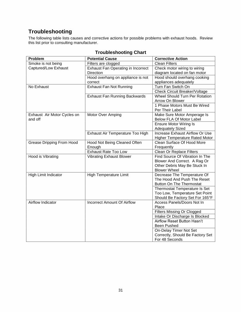
Troubleshooting
The following table lists causes and corrective actions for possible problems with exhaust hoods. Review this list prior to consulting manufacturer.
Troubleshooting Chart
Problem Potential Cause Corrective Action
Smoke is not being Captured/Low Exhaust
Filters are clogged Clean Filters
Exhaust Fan Operating in Incorrect Direction
Check motor wiring to wiring diagram located on fan motor
Hood overhang on appliance is not correct
Hood should overhang cooking appliances adequately
No Exhaust Exhaust Fan Not Running
Turn Fan Switch On
Check Circuit Breaker/Voltage
Exhaust Fan Running Backwards Wheel Should Turn Per Rotation Arrow On Blower
1 Phase Motors Must Be Wired Per Their Label
Exhaust Air Motor Cycles on and off
Motor Over Amping Make Sure Motor Amperage Is Below FLA Of Motor Label
Ensure Motor Wiring Is Adequately Sized
Exhaust Air Temperature Too High Increase Exhaust Airflow Or Use Higher Temperature Rated Motor
Grease Dripping From Hood Hood Not Being Cleaned Often Enough
Clean Surface Of Hood More Frequently
Exhaust Rate Too Low Clean Or Replace Filters
Hood is Vibrating Vibrating Exhaust Blower Find Source Of Vibration In The Blower And Correct. A Rag Or Other Debris May Be Stuck In Blower Wheel
High Limit Indicator High Temperature Limit Decrease The Temperature Of The Hood And Push The Reset Button On The Thermostat
Thermostat Temperature Is Set Too Low, Temperature Set Point Should Be Factory Set For 165°F
Airflow Indicator Incorrect Amount Of Airflow Access Panels/Doors Not In Place
Filters Missing Or Clogged
Intake Or Discharge Is Blocked
Airflow Reset Button Hasn’t Been Pushed
On-Delay Timer Not Set Correctly, Should Be Factory Set For 48 Seconds
32
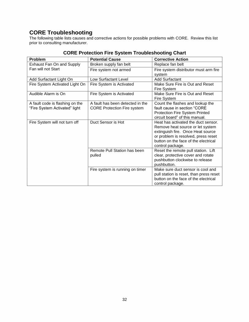
CORE Troubleshooting The following table lists causes and corrective actions for possible problems with CORE. Review this list prior to consulting manufacturer.
CORE Protection Fire System Troubleshooting Chart
Problem Potential Cause Corrective Action
Exhaust Fan On and Supply Fan will not Start
Broken supply fan belt Replace fan belt
Fire system not armed Fire system distributor must arm fire system
Add Surfactant Light On Low Surfactant Level Add Surfactant
Fire System Activated Light On Fire System is Activated Make Sure Fire is Out and Reset Fire System
Audible Alarm is On Fire System is Activated Make Sure Fire is Out and Reset Fire System
A fault code is flashing on the “Fire System Activated” light
A fault has been detected in the CORE Protection Fire system
Count the flashes and lookup the fault cause in section “CORE Protection Fire System Printed circuit board” of this manual.
Fire System will not turn off Duct Sensor is Hot Heat has activated the duct sensor. Remove heat source or let system extinguish fire. Once Heat source or problem is resolved, press reset button on the face of the electrical control package.
Remote Pull Station has been pulled
Reset the remote pull station. Lift clear, protective cover and rotate pushbutton clockwise to release pushbutton.
Fire system is running on timer Make sure duct sensor is cool and pull station is reset, than press reset button on the face of the electrical control package.

33
MAINTENANCE To guarantee trouble free operation of this system, the manufacturer suggests following these guidelines. Most problems associated with unit failures are directly related to poor service and maintenance. Record any maintenance or service performed on this equipment in the documentation section located at the end of this manual.
General Maintenance
1. Hood filters must be maintained on a daily basis to ensure proper airflow and grease extraction. If filters become clogged, replace immediately.
2. All water connections must be verified for tightness and leak-free operation. 3. The “Add Surfactant” indicating light will illuminate when the surfactant tank is ½ empty.
Surfactant must be added immediately to guarantee proper fire protection. 4. Carefully wipe away gritty substances clinging to stainless steel surfaces to avoid scratching. 5. Dilute ½ cup of laundry detergent (e.g. Tide) with one (1) gallon of warm water. 6. Soak a clean cloth in the water detergent solution and wring out the excess water. 7. Wipe the hood surfaces moving in the direction of the grain and periodically rinsing cloth in
detergent solution. 8. Using a different clean cloth soaked in clean warm water, wipe the hood surfaces to remove
all traces of the detergent solution. 9. Wipe hood surfaces dry with a clean, dry cloth. 10. Reapply stainless steel polish.
CAUTION
DO NOT use iron wool (Brillo or SOS pads), scrapers, or spatulas to clean hood!
DO NOT use the following substances on or around the hood:
1. Chlorine or chlorine based substances. 2. Acids (e.g. acetic, hydrochloric, sulfuric). 3. Chloride based substances (e.g. mercuric chloride, ferric chloride).
Vapors of the above substances can corrode stainless steel!

34
Every 6 months
1. Clean all temp sensors in hood (if equipped). 2. Check all nozzles for proper and evenly distributed water flow. If nozzles are clogged, clean or
replace. 3. Inspect the hood for grease or air leaks and repair leaks where required. 4. Clean hood plenum to prevent a mass accumulation of grease. 5. Replace HE/HEPA filter. 6. Inspect the motor and blower, remove any grease or debris. 7. Inspect hood plenum and wipe down. 8. Inspect the surfactant pump for proper operation and ensure liquid level sensor in surfactant tank
is operational. Test by manually lowering the sensor to see if the “Add Surfactant” light illuminates.
9. All plenum nozzle strainers should be removed and cleaned. Nozzles must be re-installed tightly. 10. A certified technician should test and inspect CORE system. This includes verifying proper
operation of the Firestat, all remote pull stations, proper surfactant injection and battery backup operation. Refer to the CORE Protection startup procedure to check the proper operation of these components.
Every 2 Years
1. Replace batteries for the CORE Protection Systems. The replacement battery part number is BP7-12-T2; two are required. Once the battery is disconnected, the connected equipment is not protected from power outages. The new battery must be installed immediately. Refer to the replacement battery installation guide for more details.
2. Inspect condition of all wires and plumbing. Plumbing should be free of corrosion and wire insulation must be in good condition.
After A Fire
1. Replace all nozzles. 2. Inspect all piping connections for tightness. 3. Inspect all hood lights for proper seals and security. 4. Inspect all wiring and Hood insulation to ensure all are in good condition.

35
Start-Up and Maintenance Documentation START-UP AND MEASUREMENTS SHOULD BE PERFORMED AFTER THE SYSTEM HAS BEEN AIR BALANCED (Warranty will be void without completion of this form)
Job Information
Job Name Service Company
Address Address
City City
State State
Zip Zip
Phone Number Phone Number
Fax Number Fax Number
Contact Contact
Purchase Date Start-Up Date
Hood Information
Refer to the start-up procedure in this manual to complete this section. Name Plate and Unit Information Voltage
Model Number High Limit Settings
Job Number Filters In Place
Fire System Information (When Supplied) Refer to the start-up procedure in this manual to complete this section.
Name Plate and Unit Information Field Measured Information
Serial Number Main Water line ¾” or Larger
Volts Main Water Line from Supervised Supply
Hertz Batteries plugged in and light flashes ready
Test Firestat System Activation
Test Remote Pull Station System Activation
Verify Pull Station Cover Installed
Verify Operating Water Pressure (30-70 PSI)
Verify Max Static Water Pressure (125 PSI)
Verify Constant Surfactant Injection
Verify System Activates
All Appliances Shut Down
Fire System Activated Light Illuminates
Audible Alarm Sounds
Verify Reset Button Works Correctly
System Activates on Battery Backup
Verify Surfactant Tank is Full
Verify Test Switch is in Armed Mode
36
Maintenance Record
Date Service Performed Date Service Performed
Factory Service Department
Phone: 1-866-784-6900 Fax: 1-919-554-9374