rebar and wall tie locator operating instructions · 2 thank you for your purchase of this...
TRANSCRIPT

Eng
lish
50
ator
s
Elcometer Protovale 1
Rebar and Wall Tie Loc
Operating Instruction

Eng
lish
This pr 2/31/EEC and 93/38/EEC. TheElcome tested in accordance with EUregulat he required directives.
Note: Performa frequency electromagnetic fieldstrength greater
uments Ltd.All other tradem
© Elcometer InsAll rights reserve transcribed, stored (in a retrievalsystem or otherw means (electronic, mechanical,magnetic, optica of Elcometer Instruments Ltd. A copy of this ebsite via www.elcometer.com/downloads.
Doc. No:TMA-0292 Iss. 02Part No: 18285
�
oduct meets the emc directive 89/336/EEC, amended 9ter Protovale 150 Rebar and Wall Tie Locator has been
ions governing Electromagnetic Compliance and it meets t
nce may be affected if the unit is operated within a radio than 3V/m.
and Protovale are registered trademarks of Elcometer Instrarks acknowledged.
truments Ltd. England 1994 - 2007.d. No part of this document may be reproduced, transmitted,ise) or translated into any other language in any form or by
l, manual or otherwise) without the prior written permission Instruction Manual is available for download on our W

�
1
Page
. . . . . . . . . . . . . . . . . . . . . . . . 2
. . . . . . . . . . . . . . . . . . . . . . . . 4
. . . . . . . . . . . . . . . . . . . . . . . . 6
. . . . . . . . . . . . . . . . . . . . . . . . 8
. . . . . . . . . . . . . . . . . . . . . . . . 9
. . . . . . . . . . . . . . . . . . . . . . . 14
. . . . . . . . . . . . . . . . . . . . . . . 15
. . . . . . . . . . . . . . . . . . . . . . . 15
. . . . . . . . . . . . . . . . . . . . . . . 16
CONTENTS
Section
1 About your Wall Tie and Stud Locator . . . . . . . . . . . . . . . . . . . . . . .
2 Getting started. . . . . . . . . . . . . . . . . . . . . . . . . . . . . . . . . . . . . . . . . . .
3 Locating wall ties . . . . . . . . . . . . . . . . . . . . . . . . . . . . . . . . . . . . . . . .
4 Search head orientation . . . . . . . . . . . . . . . . . . . . . . . . . . . . . . . . . . .
5 Locating rebars . . . . . . . . . . . . . . . . . . . . . . . . . . . . . . . . . . . . . . . . . .
6 Trouble shooting. . . . . . . . . . . . . . . . . . . . . . . . . . . . . . . . . . . . . . . . .
7 Maintenance . . . . . . . . . . . . . . . . . . . . . . . . . . . . . . . . . . . . . . . . . . . .
8 Spare parts and accessories . . . . . . . . . . . . . . . . . . . . . . . . . . . . . . .
9 Related equipment . . . . . . . . . . . . . . . . . . . . . . . . . . . . . . . . . . . . . . .

Wall Tie Locator. Welcome to
pection equipment for concrete
oncrete, and civil engineering inspection, from development
g product. With the purchase of network of Elcometer. For more
nstrument for fast and accurateonsists of a Control Unit and a
with two search heads for mild
s steel and is supplied with two
nze, copper and some types of
�
2
Thank you for your purchase of this Elcometer Protovale 150 Rebar andElcometer.Elcometer are world leaders in the design, manufacture and supply of insand coatings.Our concrete inspection products include a comprehensive range of cinspection equipment. Our coatings products cover all aspects of coatingthrough application to post application inspection.The Elcometer Protovale 150 Rebar and Wall Tie Locator is a world beatinthis instrument you now have access to the worldwide service and supportinformation visit our website at www.elcometer.com
1 ABOUT YOUR REBAR AND WALL TIE LOCATOR
The Elcometer Protovale 150 Rebar and Wall Tie Locator is a handheld ilocation of metallic objects in the construction industry. The instrument cSearch Head which are connected by a lead.There are two versions of the instrument:ELCOMETER P150/D: This instrument will detect mild steel and is suppliedsteel.ELCOMETER P150/E: This instrument will detect mild steel and and stainlessearch heads for mild steel and one search head for stainless steel.The 150mm (6”) search head allows the instrument to locate phosphor-brostainless steel wall tie.
�
3
int reinforcement and hoop iron.so an excellent stud locator/stud
witch on the control panel whichteel.
els only)
that this packaging is disposedal Authority for further guidance.
ties, positions and distance arest piece and check the reaction
The Elcometer P150 can also detect mild and stainless steel rebars, bed joFurthermore the Elcometer P150 can locate wiring in plaster walls and is aldetector which makes it an extremely versatile instrument.The control unit of the stainless steel version (model 150/E) is fitted with a sis used to select whether it should be sensitive or insensitive to stainless s
1.1 WHAT THE BOX CONTAINS• Elcometer Protovale 150 Rebar and Wall Tie Locator• Search head, 100 mm (4"), for mild steel - black face• Search head, 100 mm (4"), for mild steel - white face (directional)• Search head, 150 mm (6"), for stainless steel (Elcometer P150/E mod• 4 x LR6 (AA) alkaline batteries• Leather carry case• Plastic carry case• Operating instructionsThe instrument is packed in a cardboard and foam package. Please ensureof in an environmentally sensitive manner. Consult your local Environment
1.2 WALL TIE AND STUD LOCATIONAs situations in the building industry are so varied and the combination ofnot always standard, it is beneficial in non-standard situations to create a te
r detector ‘sees through’ all non
time to read these Operatingter supplier if you have any
batteries only. Sealed alkalinee used.
r output grille lines up with the
r a long period of time. This willes.
�
4
of the detector with various search heads. This can be done in air, as youmagnetic materials equally.
To maximise the benefits of your new instrument, please take someInstructions. Do not hesitate to contact Elcometer or your Elcomequestions.
2 GETTING STARTED
2.1 FITTING BATTERIESThe Elcometer Protovale 150 Rebar and Wall Tie Locator uses dry cellbatteries are recommended however rechargeable equivalents may also b4 x LR6 (AA) alkaline batteries are supplied in the kit.To fit or replace the batteries:1. Remove the instrument from the carrying case.2. Remove the battery compartment cover.3. Fit the batteries taking care to ensure correct polarity.4. Replace the battery compartment cover.5. Replace the instrument in the carrying case ensuring that the speake
hole in the case.
Note: Remove the batteries from the instrument if it is to remain unused foprevent damage to the instrument in the event of malfunction of the batteri
�
5
al contamination. Please consultn.
the batteries contain sufficientced - see “Fitting batteries” on
well clear of any metal), a point is displaying zero (0). Further
2 4 6 8 10
n
s audio
o
Elcometer 150/E only
Note: Alkaline batteries must be disposed of carefully to avoid environmentyour local Environmental Authority for information on disposal in your regio
Do not dispose of any batteries in fire.
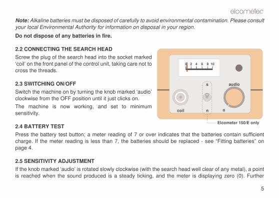
2.2 CONNECTING THE SEARCH HEADScrew the plug of the search head into the socket marked‘coil’ on the front panel of the control unit, taking care not tocross the threads.
2.3 SWITCHING ON/OFFSwitch the machine on by turning the knob marked ‘audio’clockwise from the OFF position until it just clicks on.The machine is now working, and set to minimumsensitivity.
2.4 BATTERY TESTPress the battery test button; a meter reading of 7 or over indicates thatcharge. If the meter reading is less than 7, the batteries should be replapage 4.
2.5 SENSITIVITY ADJUSTMENTIf the knob marked ‘audio’ is rotated slowly clockwise (with the search headis reached when the sound produced is a steady ticking, and the meter
0
coil

to increase in frequency through set to a low tick-over, and iswever, this setting gives moren be turned back as required.
nob until the unit is on the verget sensitive setting, and in use it this position.o that a signal is given at thell. In practice you may find that
(2") depth.
(which can happen where they and withdraw the search coile to search for the wall ties.pointing of wall ties is achievedckwise.
�
6
clockwise rotation will cause the meter to deflect to the right, and the sound a buzz to a whine. Maximum sensitivity is achieved when the sound isappropriate when searching for deeply-embedded objects. More often hosensitivity than is necessary or desirable, and the knob can and should the
3 LOCATING WALL TIES
3.1 USING MODEL 150/D (MILD STEEL)1. Connect the 100 mm (4") search head to the control unit.2. Hold the search head well away from any metal and adjust the Audio k
of producing a low frequency buzz or tickover sound. This is the moswill usually be found that the knob can be turned back somewhat fromIf a sample wall tie is available, the control knob can be adjusted sequivalent distance to which the wall ties are estimated to be in the wathe unit only needs to be switched ‘on’ to find a mild steel tie at 50 mm
3. Sweep the search head over the wall to locate wall ties or studs.If a signal is apparently being picked up from the bricks themselvesbricks contain iron ore), simply decrease the sensitivity as necessarfrom the surface of the walls until the signal reduces, and then continuThe most sensitive point of the search coil is at its centre. Accurate pinby steadily reducing the signal by turning the control knob back anticlo

�
7
n page 6.
at and fish-tail wall ties.
n page 6.
3.2 USING MODEL 150/E (MILD STEEL/STAINLESS STEEL)
TO LOCATE MILD STEEL WALL TIES1. Connect the 100 mm (4") search head to the control unit.2. Push the switch on the control panel to position ‘n’.3. Now follow the instructions given in “Using Model 150/D (mild steel)” o
TO LOCATE STAINLESS STEEL WALL TIESYour detector can be used to locate stainless-steel and phosphor-bronze b1. Connect the 150 mm (6") search head to the control unit.2. Push the switch on the control panel to position ‘s’.3. Now follow the instructions given in “Using Model 150/D (mild steel)” o
els only) orientated with its circular faceup).n either
to give ae searche head.bsence) head is throughsignal is
tation of
A
B
�
8
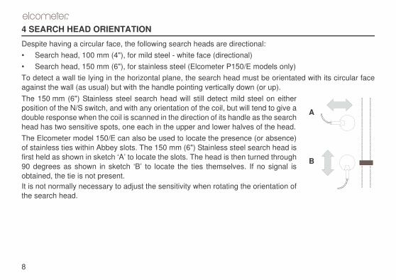
4 SEARCH HEAD ORIENTATION
Despite having a circular face, the following search heads are directional:• Search head, 100 mm (4"), for mild steel - white face (directional)• Search head, 150 mm (6"), for stainless steel (Elcometer P150/E modTo detect a wall tie lying in the horizontal plane, the search head must beagainst the wall (as usual) but with the handle pointing vertically down (or The 150 mm (6") Stainless steel search head will still detect mild steel oposition of the N/S switch, and with any orientation of the coil, but will tend double response when the coil is scanned in the direction of its handle as thhead has two sensitive spots, one each in the upper and lower halves of thThe Elcometer model 150/E can also be used to locate the presence (or aof stainless ties within Abbey slots. The 150 mm (6") Stainless steel searchfirst held as shown in sketch ‘A’ to locate the slots. The head is then turned90 degrees as shown in sketch ‘B’ to locate the ties themselves. If no obtained, the tie is not present.It is not normally necessary to adjust the sensitivity when rotating the orienthe search head.
�
9
and Wall Tie Locator to locatebar are known (or visible). Start
parallel bars, crossed bars; ande that since the machine is noteasured "in air" will be just as
16 and 2 x 12 rebars. Place on
d scan across sideways. If theroduced at all typical distances.me narrower, and it will become
axmin
5 LOCATING REBARS
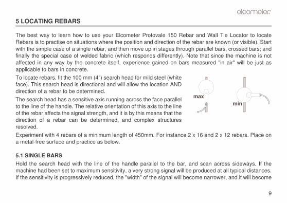
The best way to learn how to use your Elcometer Protovale 150 Rebar Rebars is to practise on situations where the position and direction of the rewith the simple case of a single rebar, and then move up in stages throughfinally the special case of welded fabric (which responds differently). Notaffected in any way by the concrete itself, experience gained on bars mapplicable to bars in concrete.To locate rebars, fit the 100 mm (4") search head for mild steel (whiteface). This search head is directional and will allow the location ANDdirection of a rebar to be determined.The search head has a sensitive axis running across the face parallelto the line of the handle. The relative orientation of this axis to the lineof the rebar affects the signal strength, and it is by this means that thedirection of a rebar can be determined, and complex structuresresolved.Experiment with 4 rebars of a minimum length of 450mm. For instance 2 xa metal-free surface and practice as below.
5.1 SINGLE BARSHold the search head with the line of the handle parallel to the bar, anmachine had been set to maximum sensitivity, a very strong signal will be pIf the sensitivity is progressively reduced, the "width" of the signal will beco
m
over the bar. The exact positione and then the other, and notingeen these two points. from the bar, the largest signalen at right angles.
�
10
apparent that the maximum signal occurs when the search head is exactly of the bar can also be found by moving the search head in, first from one sidin each case where the signal starts; the bar then lies exactly midway betwIf the search head is now rotated whilst being held at a constant distancewill be given when the handle is parallel to the bar, but little or no signal whThis direction-finding feature will be used in all situations.
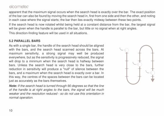
5.2 PARALLEL BARSAs with a single bar, the handle of the search head should be alignedwith the bars, and the search head scanned across the bars. Atmaximum sensitivity, a strong signal may well be producedeverywhere, but as the sensitivity is progressively reduced, the signalwill drop to a minimum when the search head is halfway betweenbars. Unless the search head is very close to the bars, furtherreduction in sensitivity will produce a "null" of silence between thebars, and a maximum when the search head is exactly over a bar. Inthis way, the centres of the spaces between the bars can be locatedjust as accurately as the bars themselves.
Note: If the search head is turned through 90 degrees so that the lineof the handle is at right angles to the bars, the signal will be muchweaker and the resolution reduced - so do not use this orientation innormal operation.
�
11
This time the vertical bars (andare largely ignored. (Note that ifr size or distance, the optimum
bar and aligned parallel to it; a space between bars, whatever
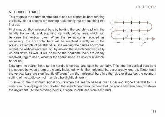
5.3 CROSSED BARSThis refers to the common structure of one set of parallel bars runningvertically, and a second set running horizontally but not touching thefirst set.First map out the horizontal bars by holding the search head with thehandle horizontal, and scanning vertically along lines which runbetween the vertical bars. When the sensitivity is reduced asnecessary, the horizontal bars will be resolved exactly as in theprevious example of parallel bars. Still keeping the handle horizontal,repeat the vertical traverses, but try moving the search head verticallyup and down as well; it will be found the horizontal bars are clearlyresolved, regardless of whether the search head is also over a verticalbar or not.Now turn the search head so the handle is vertical, and scan horizontally.the spaces between them) are clearly indicated, whilst the horizontal bars the vertical bars are significantly different from the horizontal bars in eithesetting of the audio control may also be slightly different).To sum up: the maximum signal occurs when the search head is over a minimum (or null) signal occurs when the search head is in the centre of thethe alignment. (At the crossing-points, a signal is obtained from each bar).
ally between vertical bars, the bar. Similarly, with the handleum signal at each vertical bar.
�
12
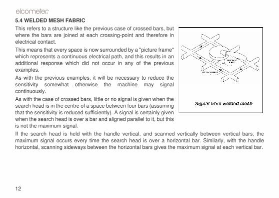
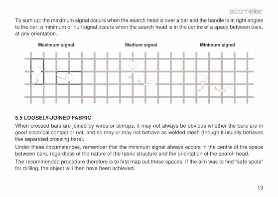
5.4 WELDED MESH FABRICThis refers to a structure like the previous case of crossed bars, butwhere the bars are joined at each crossing-point and therefore inelectrical contact.This means that every space is now surrounded by a "picture frame"which represents a continuous electrical path, and this results in anadditional response which did not occur in any of the previousexamples.As with the previous examples, it will be necessary to reduce thesensitivity somewhat otherwise the machine may signalcontinuously.As with the case of crossed bars, little or no signal is given when thesearch head is in the centre of a space between four bars (assumingthat the sensitivity is reduced sufficiently). A signal is certainly givenwhen the search head is over a bar and aligned parallel to it, but thisis not the maximum signal.If the search head is held with the handle vertical, and scanned verticmaximum signal occurs every time the search head is over a horizontalhorizontal, scanning sideways between the horizontal bars gives the maxim
�
13
and the handle is at right anglescentre of a space between bars,
bvious whether the bars are inesh (though it usually behaves
ccurs in the centre of the spacetation of the search head.
the aim was to find "safe spots"
Minimum signal
To sum up: the maximum signal occurs when the search head is over a barto the bar; a minimum or null signal occurs when the search head is in the at any orientation.
5.5 LOOSELY-JOINED FABRICWhen crossed bars are joined by wires or stirrups, it may not always be ogood electrical contact or not, and so may or may not behave as welded mlike separated crossing bars).Under these circumstances, remember that the minimum signal always obetween bars, regardless of the nature of the fabric structure and the orienThe recommended procedure therefore is to first map out these spaces. Iffor drilling, the object will then have been achieved.
Maximum signal Medium signal

nd so the bar locations are nowearch head orientation) over the
nnection.
Minimum signal
�
14
Having found all the spaces, the bars must now be between these spaces, adetermined. Investigation of the behaviour of the signal (and the effect of sbar positions will now reveal the nature of the structure itself.
6 TROUBLE SHOOTING
Any fault conditions encountered can usually be cleared by checking:• the battery voltage and cell polarity• the battery contacts for spring tension and corrosion• the search head plug and socket for good electrical and mechanical co
Maximum signalMedium signal
�
15
ive many years reliable service
n of dirt and moisture after use.
and free from mud and grit.t is switched OFF after use; and time.e unlikely event of a fault, the Elcometer. Contact details can
ebsite, www.elcometer.com
r or your local supplier.
Sales Part No.
TW999198D
TW999198F
TW999198E
7 MAINTENANCE
The Elcometer Protovale 150 Rebar and Wall Tie Locator is designed to gunder normal operating and storage conditions.No special maintenance is necessary, though the unit should be wiped cleaTwo points in particular will ensure long-term trouble free operation:• To prevent damage to the coil plug and socket, keep the threads dean• To prevent corrosion damage from leaking batteries: make sure the uni
remove the batteries if the unit is to be stored unused for any period ofThe instrument does not contain any user-serviceable components. In thinstrument should be returned to your local Elcometer supplier or directly tobe found on the outside cover of these instructions, or on the Elcometer w
8 SPARE PARTS AND ACCESSORIES
The following replacement and optional items are available from Elcomete
Description
100 mm (4") Locator Search Coil
100 mm (4") Directional Search Coil
150 mm (6") Stainless steel Search Coil - for Elcometer 150/E only

ipment. Users of the Elcometering Elcometer products:
www.elcometer.com
�
16
9 RELATED EQUIPMENT
Elcometer produces a wide range of concrete and coatings inspection equProtovale 150 Rebar and Wall Tie Locator may also benefit from the follow• Elcometer Adhesion and Bond Strength Testers• Elcometer Concrete Crack Microscopes• Elcometer Concrete Moisture Meters• Elcometer Concrete Test Hammers• Elcometer Concrete CovermetersFor further information contact Elcometer, your Elcometer supplier or visit