realtime workshop 7 getting started guide
TRANSCRIPT

Real-Time Workshop® 7Getting Started Guide
Downloaded from www.Manualslib.com manuals search engine
How to Contact The MathWorks
www.mathworks.com Webcomp.soft-sys.matlab Newsgroupwww.mathworks.com/contact_TS.html Technical Support
[email protected] Product enhancement [email protected] Bug [email protected] Documentation error [email protected] Order status, license renewals, [email protected] Sales, pricing, and general information
508-647-7000 (Phone)
508-647-7001 (Fax)
The MathWorks, Inc.3 Apple Hill DriveNatick, MA 01760-2098For contact information about worldwide offices, see the MathWorks Web site.
Real-Time Workshop® Getting Started Guide
© COPYRIGHT 2002–2010 by The MathWorks, Inc.The software described in this document is furnished under a license agreement. The software may be usedor copied only under the terms of the license agreement. No part of this manual may be photocopied orreproduced in any form without prior written consent from The MathWorks, Inc.
FEDERAL ACQUISITION: This provision applies to all acquisitions of the Program and Documentationby, for, or through the federal government of the United States. By accepting delivery of the Programor Documentation, the government hereby agrees that this software or documentation qualifies ascommercial computer software or commercial computer software documentation as such terms are usedor defined in FAR 12.212, DFARS Part 227.72, and DFARS 252.227-7014. Accordingly, the terms andconditions of this Agreement and only those rights specified in this Agreement, shall pertain to and governthe use, modification, reproduction, release, performance, display, and disclosure of the Program andDocumentation by the federal government (or other entity acquiring for or through the federal government)and shall supersede any conflicting contractual terms or conditions. If this License fails to meet thegovernment’s needs or is inconsistent in any respect with federal procurement law, the government agreesto return the Program and Documentation, unused, to The MathWorks, Inc.
Trademarks
MATLAB and Simulink are registered trademarks of The MathWorks, Inc. Seewww.mathworks.com/trademarks for a list of additional trademarks. Other product or brandnames may be trademarks or registered trademarks of their respective holders.
Patents
The MathWorks products are protected by one or more U.S. patents. Please seewww.mathworks.com/patents for more information.
Downloaded from www.Manualslib.com manuals search engine

Revision HistoryJuly 2002 First printing New for Version 5.0 (Release 13)June 2004 Second printing Revised for Version 6.0 (Release 14)October 2004 Third printing Revised for Version 6.1 (Release 14SP1)March 2005 Online only Revised for Version 6.2 (Release 14SP2)September 2005 Fourth printing Revised for Version 6.3 (Release 14SP3)March 2006 Online Only Revised for Version 6.4 (Release 2006a)September 2006 Online Only Revised for Version 6.5 (Release 2006b)March 2007 Fifth printing Revised for Version 6.6 (Release 2007a)September 2007 Online Only Revised for Version 7.0 (Release 2007b)March 2008 Online Only Revised for Version 7.1 (Release 2008a)October 2008 Sixth printing Revised for Version 7.2 (Release 2008b)March 2009 Online Only Revised for Version 7.3 (Release 2009a)September 2009 Online Only Revised for Version 7.4 (Release 2009b)March 2010 Online Only Revised for Version 7.5 (Release 2010a)
Downloaded from www.Manualslib.com manuals search engine

Contents
Getting Started with Real-Time WorkshopTechnology
1What You Need to Know to Use Real-Time WorkshopTechnology . . . . . . . . . . . . . . . . . . . . . . . . . . . . . . . . . . . . . 1-2
What You Can Accomplish Using Real-Time WorkshopTechnology . . . . . . . . . . . . . . . . . . . . . . . . . . . . . . . . . . . . . 1-3
How the Technology Can Fit Into Your DevelopmentProcess . . . . . . . . . . . . . . . . . . . . . . . . . . . . . . . . . . . . . . . . . 1-6Tools for Algorithm Development . . . . . . . . . . . . . . . . . . . . 1-6Target Environments . . . . . . . . . . . . . . . . . . . . . . . . . . . . . . 1-10Applications . . . . . . . . . . . . . . . . . . . . . . . . . . . . . . . . . . . . . . 1-14
How You Can Apply the Technology to the V-Model forSystem Development . . . . . . . . . . . . . . . . . . . . . . . . . . . . . 1-16What Is the V-Model? . . . . . . . . . . . . . . . . . . . . . . . . . . . . . . 1-16Types of Simulation and Prototyping . . . . . . . . . . . . . . . . . 1-18Types of In-the-Loop Testing for Verification andValidation . . . . . . . . . . . . . . . . . . . . . . . . . . . . . . . . . . . . . 1-19
How to Develop an Application Using Real-TimeWorkshop Software
2Workflow for Developing Applications Using Real-TimeWorkshop Software . . . . . . . . . . . . . . . . . . . . . . . . . . . . . . 2-2
Mapping Application Requirements to ConfigurationOptions . . . . . . . . . . . . . . . . . . . . . . . . . . . . . . . . . . . . . . . . . 2-4
v
Downloaded from www.Manualslib.com manuals search engine
Adjusting Configuration Settings . . . . . . . . . . . . . . . . . . . 2-6
Running the Model Advisor . . . . . . . . . . . . . . . . . . . . . . . . . 2-7
Generating Code . . . . . . . . . . . . . . . . . . . . . . . . . . . . . . . . . . 2-10
Building an Executable Program . . . . . . . . . . . . . . . . . . . . 2-11
Verifying the Executable Program . . . . . . . . . . . . . . . . . . 2-14
Naming and Saving the Configuration Set . . . . . . . . . . . 2-15Adding and Copying Configuration Sets . . . . . . . . . . . . . . . 2-15
Documenting the Project . . . . . . . . . . . . . . . . . . . . . . . . . . . 2-17
Working with the Real-TimeWorkshop Software
3Demonstration Model: rtwdemo_f14 . . . . . . . . . . . . . . . . . 3-3
Building a Generic Real-Time Program . . . . . . . . . . . . . . 3-4Tutorial Overview . . . . . . . . . . . . . . . . . . . . . . . . . . . . . . . . . 3-4Working and Build Directories . . . . . . . . . . . . . . . . . . . . . . . 3-4Setting Program Parameters . . . . . . . . . . . . . . . . . . . . . . . . 3-5Selecting the Target Configuration . . . . . . . . . . . . . . . . . . . 3-7Building and Running the Program . . . . . . . . . . . . . . . . . . . 3-13Contents of the Build Directory . . . . . . . . . . . . . . . . . . . . . . 3-15
Data Logging . . . . . . . . . . . . . . . . . . . . . . . . . . . . . . . . . . . . . . 3-18Tutorial Overview . . . . . . . . . . . . . . . . . . . . . . . . . . . . . . . . . 3-18Data Logging During Simulation . . . . . . . . . . . . . . . . . . . . . 3-19Data Logging from Generated Code . . . . . . . . . . . . . . . . . . . 3-22
Code Verification . . . . . . . . . . . . . . . . . . . . . . . . . . . . . . . . . . 3-27Tutorial Overview . . . . . . . . . . . . . . . . . . . . . . . . . . . . . . . . . 3-27Logging Signals via Scope Blocks . . . . . . . . . . . . . . . . . . . . . 3-27
vi Contents
Downloaded from www.Manualslib.com manuals search engine

Logging Simulation Data . . . . . . . . . . . . . . . . . . . . . . . . . . . 3-29Logging Data from the Generated Program . . . . . . . . . . . . 3-29Comparing Numerical Results of the Simulation and theGenerated Program . . . . . . . . . . . . . . . . . . . . . . . . . . . . . 3-31
First Look at Generated Code . . . . . . . . . . . . . . . . . . . . . . . 3-33Tutorial Overview . . . . . . . . . . . . . . . . . . . . . . . . . . . . . . . . . 3-33Setting Up the Model . . . . . . . . . . . . . . . . . . . . . . . . . . . . . . 3-33Generating Code Without Buffer Optimization . . . . . . . . . 3-35Generating Code With Buffer Optimization . . . . . . . . . . . . 3-39Further Optimization: Expression Folding . . . . . . . . . . . . . 3-41HTML Code Generation Reports . . . . . . . . . . . . . . . . . . . . . 3-44
Working with External Mode Using GRT . . . . . . . . . . . . . 3-47Tutorial Overview . . . . . . . . . . . . . . . . . . . . . . . . . . . . . . . . . 3-47Setting Up the Model . . . . . . . . . . . . . . . . . . . . . . . . . . . . . . 3-48Building the Target Executable . . . . . . . . . . . . . . . . . . . . . . 3-50Running the External Mode Target Program . . . . . . . . . . . 3-54Tuning Parameters . . . . . . . . . . . . . . . . . . . . . . . . . . . . . . . . 3-58
Generating Code for a Referenced Model . . . . . . . . . . . . 3-60Tutorial Overview . . . . . . . . . . . . . . . . . . . . . . . . . . . . . . . . . 3-60Creating and Configuring a Subsystem Within the vdpModel . . . . . . . . . . . . . . . . . . . . . . . . . . . . . . . . . . . . . . . . . 3-60
Converting the Model to Use Model Referencing . . . . . . . . 3-63Generating Model Reference Code for a GRT Target . . . . . 3-67Working with Project Directories . . . . . . . . . . . . . . . . . . . . . 3-70
Documenting a Code Generation Project . . . . . . . . . . . . 3-72Tutorial Overview . . . . . . . . . . . . . . . . . . . . . . . . . . . . . . . . . 3-72Generating Code for the Model . . . . . . . . . . . . . . . . . . . . . . 3-73Opening Report Generator . . . . . . . . . . . . . . . . . . . . . . . . . . 3-74Setting Report Output Options . . . . . . . . . . . . . . . . . . . . . . 3-75Specifying Models and Subsystems to Include in aReport . . . . . . . . . . . . . . . . . . . . . . . . . . . . . . . . . . . . . . . . 3-77
Setting Component Options . . . . . . . . . . . . . . . . . . . . . . . . . 3-77Generating the Report . . . . . . . . . . . . . . . . . . . . . . . . . . . . . 3-78Reviewing the Generated Report . . . . . . . . . . . . . . . . . . . . . 3-78
vii
Downloaded from www.Manualslib.com manuals search engine

Index
viii Contents
Downloaded from www.Manualslib.com manuals search engine

1
Getting Started withReal-Time WorkshopTechnology
• “What You Need to Know to Use Real-Time Workshop Technology” onpage 1-2
• “What You Can Accomplish Using Real-Time Workshop Technology” onpage 1-3
• “How the Technology Can Fit Into Your Development Process” on page 1-6
• “How You Can Apply the Technology to the V-Model for SystemDevelopment” on page 1-16
Downloaded from www.Manualslib.com manuals search engine

1 Getting Started with Real-Time Workshop® Technology
What You Need to Know to Use Real-Time WorkshopTechnology
Before you use Real-Time Workshop® technology, you should be familiar with
• Using the Simulink® and Stateflow® software to create models or statemachines as block diagrams, running such simulations in Simulink, andinterpreting output in the MATLAB® workspace
• High-level programming language concepts applied to real-time systems
While you do not need to program in C or other programming languages tocreate, test, and deploy real-time systems using the Real-Time Workshopsoftware, successful emulation and deployment of real-time systems requiresfamiliarity with parameters and design constraints. The Real-Time Workshopdocumentation assumes you have a basic understanding of real-time systemconcepts, terminology, and environments.
If you are familiar with C language constructs and want to learn about howto map commonly used C constructs to code generated from model designpatterns that include Simulink blocks, Stateflow charts, and EmbeddedMATLAB® functions, see Technical Solution 1-6AWSQ9 on the MathWorks™Web site.
1-2
Downloaded from www.Manualslib.com manuals search engine
What You Can Accomplish Using Real-Time Workshop® Technology
What You Can Accomplish Using Real-Time WorkshopTechnology
Real-Time Workshop technology generates C or C++ source code andexecutables for algorithms that you model graphically in the Simulinkenvironment or programmatically with the Embedded MATLAB languagesubset. You can generate code for any Simulink blocks and MATLABfunctions that are useful for real-time or embedded applications. Thegenerated source code and executables for floating-point algorithms matchthe functional behavior of Simulink simulations and Embedded MATLABcode execution to high degrees of fidelity. Using the Simulink® Fixed Point™product, you can generate fixed-point code that provides a bit-wise accuratematch to model simulation results. Such broad support and high degreesof accuracy are possible because Real-Time Workshop technology is tightlyintegrated with the MATLAB and Simulink execution and simulationengines. In fact, the built-in accelerated simulation modes in Simulink useReal-Time Workshop technology.
You apply Real-Time Workshop technology explicitly with the Real-TimeWorkshop and Real-Time Workshop® Embedded Coder™ products. Using theReal-Time Workshop product, you can
• Generate source code and executables for discrete-time, continuous-time(fixed-step), and hybrid systems modeled in Simulink
• Use the generated code for real-time and non-real-time applications,including simulation acceleration, rapid prototyping, andhardware-in-the-loop (HIL) testing
• Tune and monitor the generated code by using Simulink blocks and built-inanalysis capabilities, or run and interact with the code completely outsidethe MATLAB and Simulink environment
• Generate code for finite state machines modeled in Stateflow event-basedmodeling software, using the optional Stateflow® Coder™ product
• Produce source code for many Simulink products and blocksets providedby The MathWorks™ and third-party vendors.
The Real-Time Workshop Embedded Coder product extends the Real-TimeWorkshop product with features that are important for embedded software
1-3
Downloaded from www.Manualslib.com manuals search engine

1 Getting Started with Real-Time Workshop® Technology
development. Using the Real-Time Workshop Embedded Coder add-onproduct, you gain access to all aspects of Real-Time Workshop technologyand can generate code that has the clarity and efficiency of professionalhandwritten code. For example, you can
• Generate code that is compact and fast, which is essential for real-timesimulators, on-target rapid prototyping boards, microprocessors used inmass production, and embedded systems
• Customize the appearance of the generated code
• Optimize the generated code for a specific target environment
• Integrate existing (legacy) applications, functions, and data
• Enable tracing, reporting, and testing options that facilitate codeverification activities
The following table compares typical applications and key capabilities forthese two code generation products.
Product Typical Applications Key Capabilities
Real-Time Workshop Simulation acceleration
Simulink model encryption
Rapid prototyping
HIL testing
Generate code for discrete-time,continuous-time (fixed-step),and hybrid systems modeled inSimulink
Tune and monitor the execution ofgenerated code by using Simulinkblocks and built-in analysiscapabilities or by running andinteracting with the code outsidethe MATLAB and Simulinkenvironment
Generate code for finite statemachines modeled in Stateflowevent-based modeling software,using the optional Stateflow Coderproduct
1-4
Downloaded from www.Manualslib.com manuals search engine

What You Can Accomplish Using Real-Time Workshop® Technology
Product Typical Applications Key Capabilities
Generate code for manyMathWorks and third-partySimulink products and blocksets
Integrate existing applications,functions, and data
Real-Time WorkshopEmbedded Coder
All applications listed for theReal-Time Workshop product
Embedded systems
On-target rapid prototypingboards
Microprocessors used in massproduction
All capabilities listed for theReal-Time Workshop product
Generate code that has the clarityand efficiency of professionalhandwritten code
Customize the appearance andperformance of the code for specifictarget environments
Enable tracing, reporting, andtesting options that facilitate codeverification activities
1-5
Downloaded from www.Manualslib.com manuals search engine

1 Getting Started with Real-Time Workshop® Technology
How the Technology Can Fit Into Your DevelopmentProcess
In this section...
“Tools for Algorithm Development” on page 1-6
“Target Environments” on page 1-10
“Applications” on page 1-14
Tools for Algorithm DevelopmentYou can use Real-Time Workshop technology to generate standalone C or C++source code for algorithms that you develop the following ways:
• With MATLAB code, using the Embedded MATLAB language subset
• As Simulink models
• With MATLAB code that you incorporate into Simulink models
The Embedded MATLAB language subset supports MATLAB operatorsand functions for floating-point and fixed-point math. Simulink support fordynamic system simulation, conditional execution of system semantics, andlarge model hierarchies provides an environment for modeling periodic andevent-driven algorithms commonly found in embedded systems. Real-TimeWorkshop technology generates code for most Simulink blocks and manyMathWorks products.
If you are familiar with C language constructs and want to learn about howto map commonly used C constructs to code generated from model designpatterns that include Simulink blocks, Stateflow charts, and EmbeddedMATLAB functions, see Technical Solution 1-6AWSQ9 on the MathWorksWeb site.
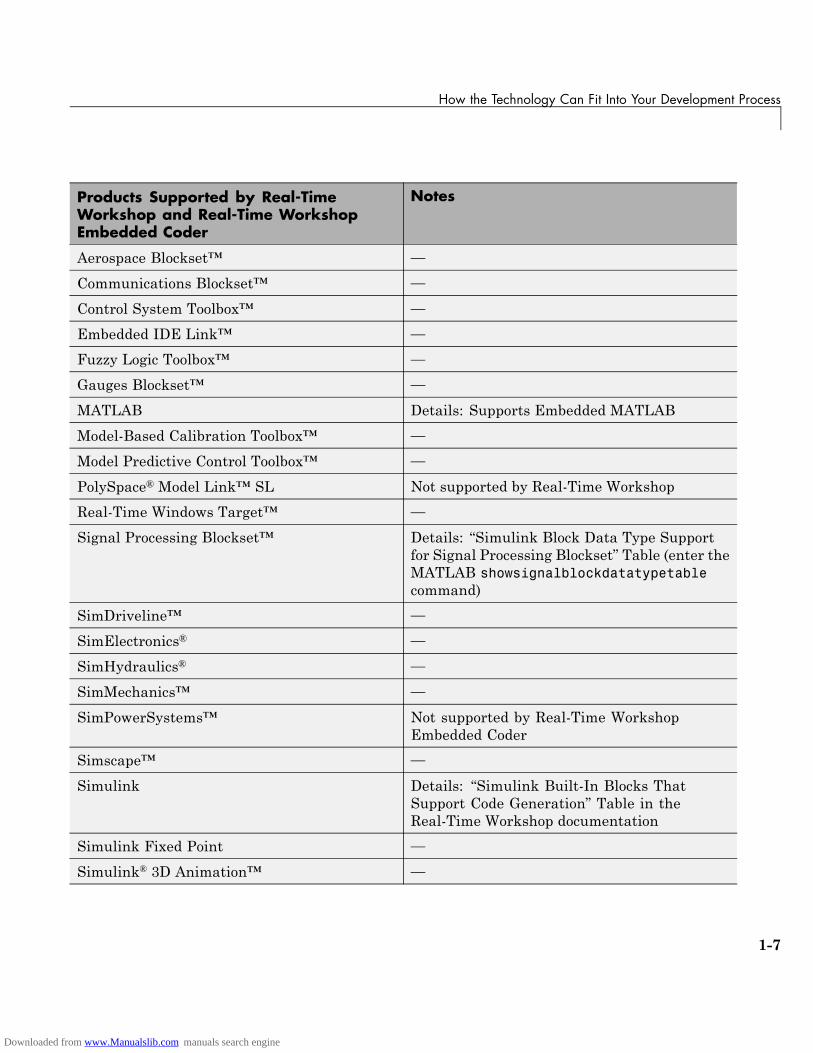
The following table lists products that the Real-Time Workshop andReal-Time Workshop Embedded Coder software support.
1-6
Downloaded from www.Manualslib.com manuals search engine
How the Technology Can Fit Into Your Development Process
Products Supported by Real-TimeWorkshop and Real-Time WorkshopEmbedded Coder
Notes
Aerospace Blockset™ —
Communications Blockset™ —
Control System Toolbox™ —
Embedded IDE Link™ —
Fuzzy Logic Toolbox™ —
Gauges Blockset™ —
MATLAB Details: Supports Embedded MATLAB
Model-Based Calibration Toolbox™ —
Model Predictive Control Toolbox™ —
PolySpace® Model Link™ SL Not supported by Real-Time Workshop
Real-Time Windows Target™ —
Signal Processing Blockset™ Details: “Simulink Block Data Type Supportfor Signal Processing Blockset” Table (enter theMATLAB showsignalblockdatatypetablecommand)
SimDriveline™ —
SimElectronics® —
SimHydraulics® —
SimMechanics™ —
SimPowerSystems™ Not supported by Real-Time WorkshopEmbedded Coder
Simscape™ —
Simulink Details: “Simulink Built-In Blocks ThatSupport Code Generation” Table in theReal-Time Workshop documentation
Simulink Fixed Point —
Simulink® 3D Animation™ —
1-7
Downloaded from www.Manualslib.com manuals search engine
1 Getting Started with Real-Time Workshop® Technology
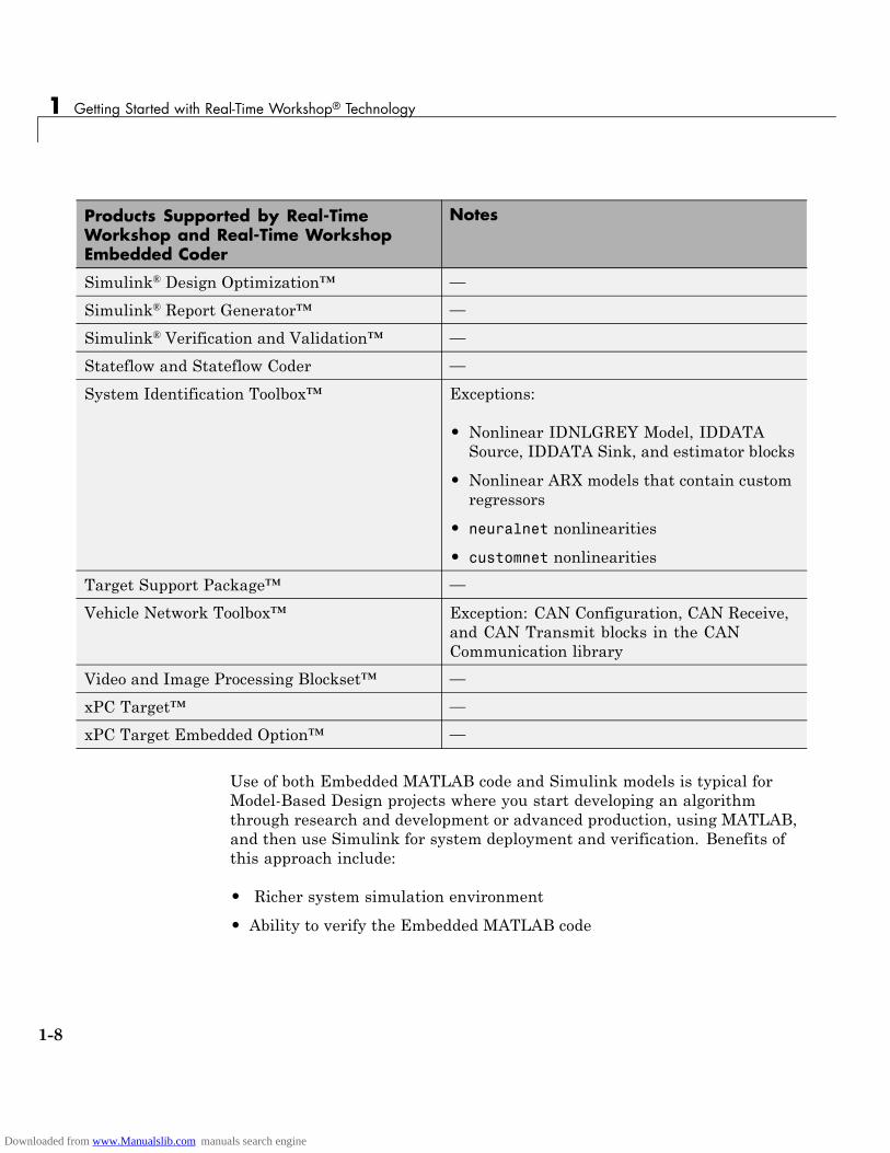
Products Supported by Real-TimeWorkshop and Real-Time WorkshopEmbedded Coder
Notes
Simulink® Design Optimization™ —
Simulink® Report Generator™ —
Simulink® Verification and Validation™ —
Stateflow and Stateflow Coder —
System Identification Toolbox™ Exceptions:
• Nonlinear IDNLGREY Model, IDDATASource, IDDATA Sink, and estimator blocks
• Nonlinear ARX models that contain customregressors
• neuralnet nonlinearities
• customnet nonlinearities
Target Support Package™ —
Vehicle Network Toolbox™ Exception: CAN Configuration, CAN Receive,and CAN Transmit blocks in the CANCommunication library
Video and Image Processing Blockset™ —
xPC Target™ —
xPC Target Embedded Option™ —
Use of both Embedded MATLAB code and Simulink models is typical forModel-Based Design projects where you start developing an algorithmthrough research and development or advanced production, using MATLAB,and then use Simulink for system deployment and verification. Benefits ofthis approach include:
• Richer system simulation environment
• Ability to verify the Embedded MATLAB code
1-8
Downloaded from www.Manualslib.com manuals search engine
How the Technology Can Fit Into Your Development Process
• Real-Time Workshop and Real-Time Workshop Embedded Coder C/C++code generation for the model and embedded MATLAB code
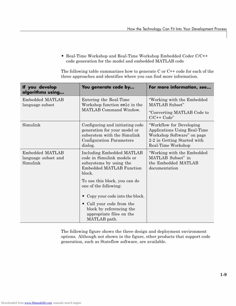
The following table summarizes how to generate C or C++ code for each of thethree approaches and identifies where you can find more information.
If you developalgorithms using...
You generate code by... For more information, see...
Embedded MATLABlanguage subset
Entering the Real-TimeWorkshop function emlc in theMATLAB Command Window.
“Working with the EmbeddedMATLAB Subset”
“Converting MATLAB Code toC/C++ Code”
Simulink Configuring and initiating codegeneration for your model orsubsystem with the SimulinkConfiguration Parametersdialog.
“Workflow for DevelopingApplications Using Real-TimeWorkshop Software” on page2-2 in Getting Started withReal-Time Workshop
Embedded MATLABlanguage subset andSimulink
Including Embedded MATLABcode in Simulink models orsubsystems by using theEmbedded MATLAB Functionblock.
To use this block, you can doone of the following:
• Copy your code into the block.
• Call your code from theblock by referencing theappropriate files on theMATLAB path.
“Working with the EmbeddedMATLAB Subset” inthe Embedded MATLABdocumentation
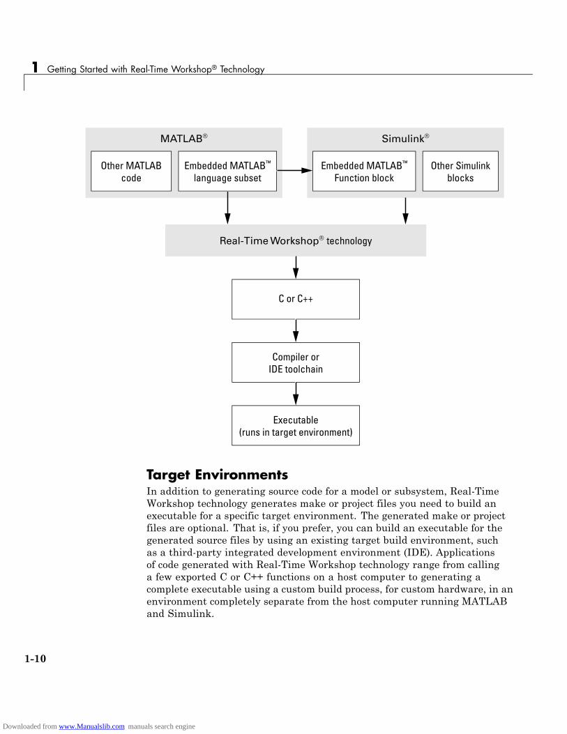
The following figure shows the three design and deployment environmentoptions. Although not shown in the figure, other products that support codegeneration, such as Stateflow software, are available.
1-9
Downloaded from www.Manualslib.com manuals search engine
1 Getting Started with Real-Time Workshop® Technology
MATLAB® Simulink®
Other MATLABcode
Embedded MATLAB™
language subsetEmbedded MATLAB™
Function block
Real-Time Workshop® technology
C or C++
Compiler orIDE toolchain
Executable(runs in target environment)
Other Simulinkblocks
Target EnvironmentsIn addition to generating source code for a model or subsystem, Real-TimeWorkshop technology generates make or project files you need to build anexecutable for a specific target environment. The generated make or projectfiles are optional. That is, if you prefer, you can build an executable for thegenerated source files by using an existing target build environment, suchas a third-party integrated development environment (IDE). Applicationsof code generated with Real-Time Workshop technology range from callinga few exported C or C++ functions on a host computer to generating acomplete executable using a custom build process, for custom hardware, in anenvironment completely separate from the host computer running MATLABand Simulink.
1-10
Downloaded from www.Manualslib.com manuals search engine
How the Technology Can Fit Into Your Development Process
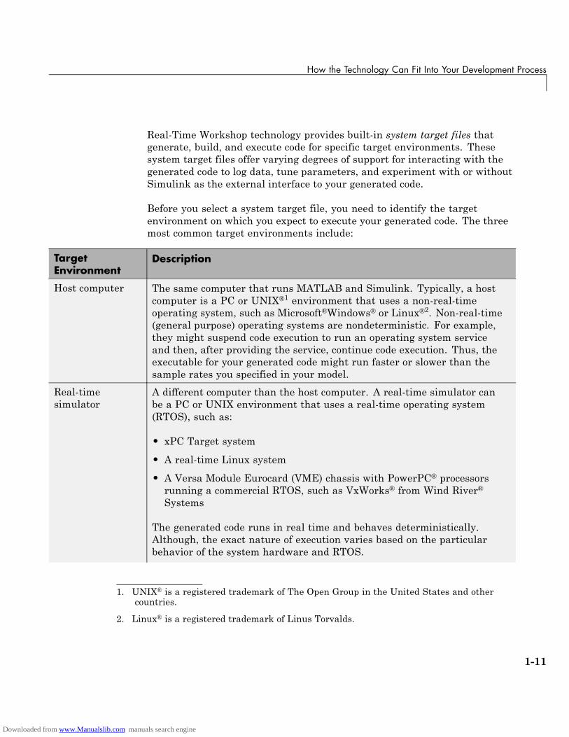
Real-Time Workshop technology provides built-in system target files thatgenerate, build, and execute code for specific target environments. Thesesystem target files offer varying degrees of support for interacting with thegenerated code to log data, tune parameters, and experiment with or withoutSimulink as the external interface to your generated code.
Before you select a system target file, you need to identify the targetenvironment on which you expect to execute your generated code. The threemost common target environments include:
TargetEnvironment
Description
Host computer The same computer that runs MATLAB and Simulink. Typically, a hostcomputer is a PC or UNIX®1 environment that uses a non-real-timeoperating system, such as Microsoft®Windows® or Linux®2. Non-real-time(general purpose) operating systems are nondeterministic. For example,they might suspend code execution to run an operating system serviceand then, after providing the service, continue code execution. Thus, theexecutable for your generated code might run faster or slower than thesample rates you specified in your model.
Real-timesimulator
A different computer than the host computer. A real-time simulator canbe a PC or UNIX environment that uses a real-time operating system(RTOS), such as:
• xPC Target system
• A real-time Linux system
• A Versa Module Eurocard (VME) chassis with PowerPC® processorsrunning a commercial RTOS, such as VxWorks® from Wind River®
Systems
The generated code runs in real time and behaves deterministically.Although, the exact nature of execution varies based on the particularbehavior of the system hardware and RTOS.
1. UNIX® is a registered trademark of The Open Group in the United States and othercountries.
2. Linux® is a registered trademark of Linus Torvalds.
1-11
Downloaded from www.Manualslib.com manuals search engine
1 Getting Started with Real-Time Workshop® Technology
TargetEnvironment
Description
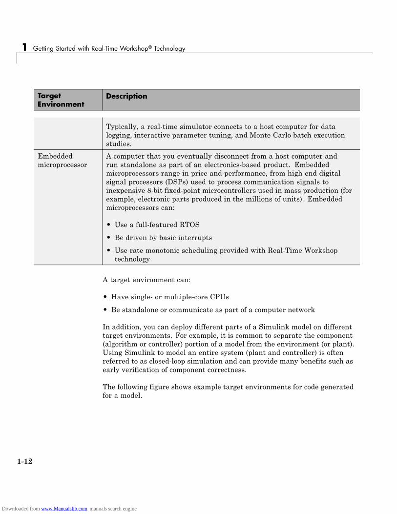
Typically, a real-time simulator connects to a host computer for datalogging, interactive parameter tuning, and Monte Carlo batch executionstudies.
Embeddedmicroprocessor
A computer that you eventually disconnect from a host computer andrun standalone as part of an electronics-based product. Embeddedmicroprocessors range in price and performance, from high-end digitalsignal processors (DSPs) used to process communication signals toinexpensive 8-bit fixed-point microcontrollers used in mass production (forexample, electronic parts produced in the millions of units). Embeddedmicroprocessors can:
• Use a full-featured RTOS
• Be driven by basic interrupts
• Use rate monotonic scheduling provided with Real-Time Workshoptechnology
A target environment can:
• Have single- or multiple-core CPUs
• Be standalone or communicate as part of a computer network
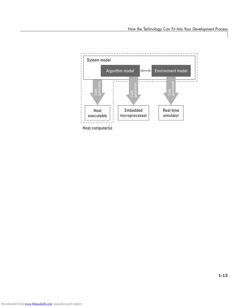
In addition, you can deploy different parts of a Simulink model on differenttarget environments. For example, it is common to separate the component(algorithm or controller) portion of a model from the environment (or plant).Using Simulink to model an entire system (plant and controller) is oftenreferred to as closed-loop simulation and can provide many benefits such asearly verification of component correctness.
The following figure shows example target environments for code generatedfor a model.
1-12
Downloaded from www.Manualslib.com manuals search engine
How the Technology Can Fit Into Your Development Process
Code
gene
ratio
n
Algorithm model
Hostexecutable
System model
Host computer(s)
Embeddedmicroprocessor
Real-timesimulator
Environment model
Code
gene
ratio
n
Code
gene
ratio
n
1-13
Downloaded from www.Manualslib.com manuals search engine
1 Getting Started with Real-Time Workshop® Technology
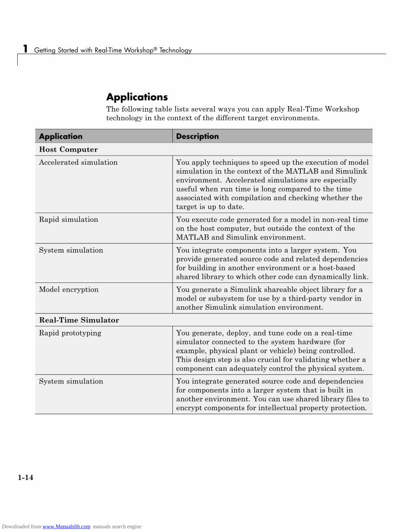
ApplicationsThe following table lists several ways you can apply Real-Time Workshoptechnology in the context of the different target environments.
Application Description
Host Computer
Accelerated simulation You apply techniques to speed up the execution of modelsimulation in the context of the MATLAB and Simulinkenvironment. Accelerated simulations are especiallyuseful when run time is long compared to the timeassociated with compilation and checking whether thetarget is up to date.
Rapid simulation You execute code generated for a model in non-real timeon the host computer, but outside the context of theMATLAB and Simulink environment.
System simulation You integrate components into a larger system. Youprovide generated source code and related dependenciesfor building in another environment or a host-basedshared library to which other code can dynamically link.
Model encryption You generate a Simulink shareable object library for amodel or subsystem for use by a third-party vendor inanother Simulink simulation environment.
Real-Time Simulator
Rapid prototyping You generate, deploy, and tune code on a real-timesimulator connected to the system hardware (forexample, physical plant or vehicle) being controlled.This design step is also crucial for validating whether acomponent can adequately control the physical system.
System simulation You integrate generated source code and dependenciesfor components into a larger system that is built inanother environment. You can use shared library files toencrypt components for intellectual property protection.
1-14
Downloaded from www.Manualslib.com manuals search engine
How the Technology Can Fit Into Your Development Process
Application Description
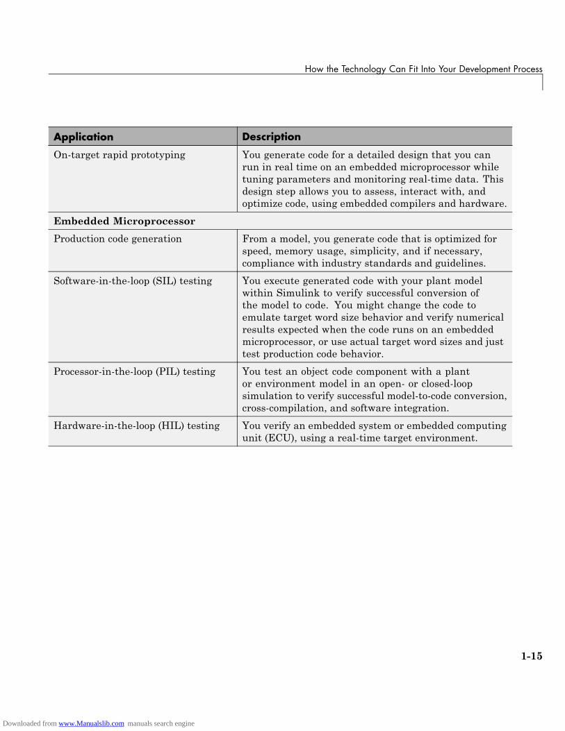
On-target rapid prototyping You generate code for a detailed design that you canrun in real time on an embedded microprocessor whiletuning parameters and monitoring real-time data. Thisdesign step allows you to assess, interact with, andoptimize code, using embedded compilers and hardware.
Embedded Microprocessor
Production code generation From a model, you generate code that is optimized forspeed, memory usage, simplicity, and if necessary,compliance with industry standards and guidelines.
Software-in-the-loop (SIL) testing You execute generated code with your plant modelwithin Simulink to verify successful conversion ofthe model to code. You might change the code toemulate target word size behavior and verify numericalresults expected when the code runs on an embeddedmicroprocessor, or use actual target word sizes and justtest production code behavior.
Processor-in-the-loop (PIL) testing You test an object code component with a plantor environment model in an open- or closed-loopsimulation to verify successful model-to-code conversion,cross-compilation, and software integration.
Hardware-in-the-loop (HIL) testing You verify an embedded system or embedded computingunit (ECU), using a real-time target environment.
1-15
Downloaded from www.Manualslib.com manuals search engine
1 Getting Started with Real-Time Workshop® Technology
How You Can Apply the Technology to the V-Model forSystem Development
In this section...
“What Is the V-Model?” on page 1-16
“Types of Simulation and Prototyping” on page 1-18
“Types of In-the-Loop Testing for Verification and Validation” on page 1-19
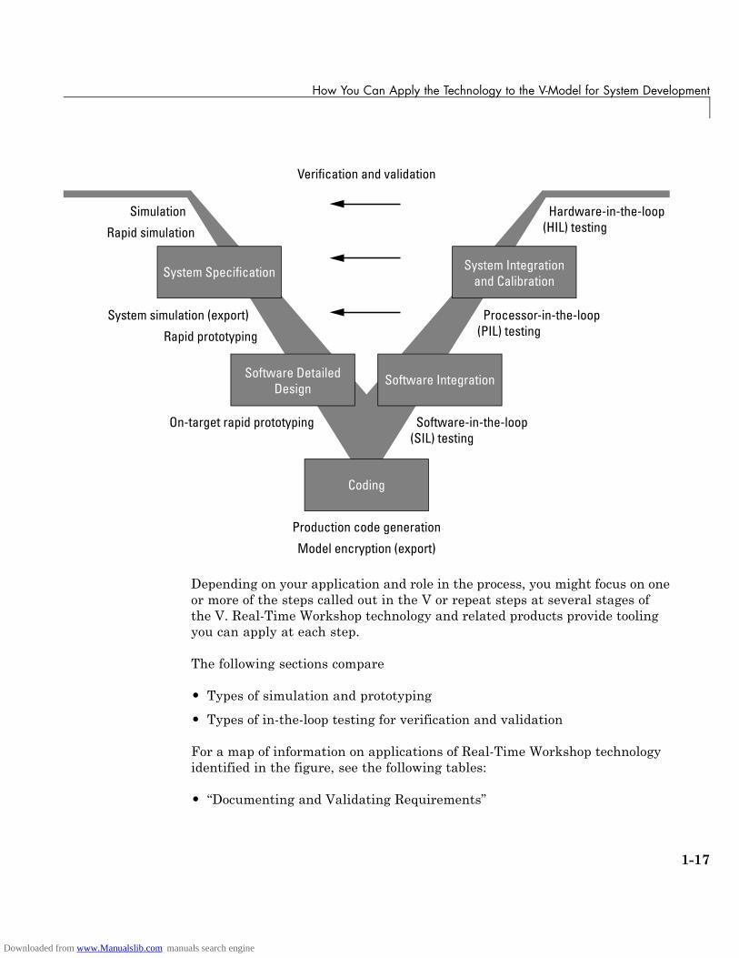
What Is the V-Model?The V-model is a representation of system development that highlightsverification and validation steps in the system development process. As thefollowing figure shows, the left side of the V identifies steps that lead to codegeneration, including requirements analysis, system specification, detailedsoftware design, and coding. The right side focuses on the verification andvalidation of steps cited on the left side, including software integration andsystem integration.
1-16
Downloaded from www.Manualslib.com manuals search engine
How You Can Apply the Technology to the V-Model for System Development
System Specification
Coding
Software DetailedDesign
System Integrationand Calibration
Hardware-in-the-loop(HIL) testing
Processor-in-the-loop(PIL) testing
Simulation
Rapid simulation
System simulation (export)
Rapid prototyping
Software-in-the-loop(SIL) testing
On-target rapid prototyping
Production code generation
Model encryption (export)
Verification and validation
Software Integration
Depending on your application and role in the process, you might focus on oneor more of the steps called out in the V or repeat steps at several stages ofthe V. Real-Time Workshop technology and related products provide toolingyou can apply at each step.
The following sections compare
• Types of simulation and prototyping
• Types of in-the-loop testing for verification and validation
For a map of information on applications of Real-Time Workshop technologyidentified in the figure, see the following tables:
• “Documenting and Validating Requirements”
1-17
Downloaded from www.Manualslib.com manuals search engine
1 Getting Started with Real-Time Workshop® Technology
• “Developing a Model Executable Specification”
• “Developing a Detailed Software Design”
• “Generating the Application Code”
• “Integrating and Verifying Software”
• “Integrating, Verifying, and Calibrating System Components”
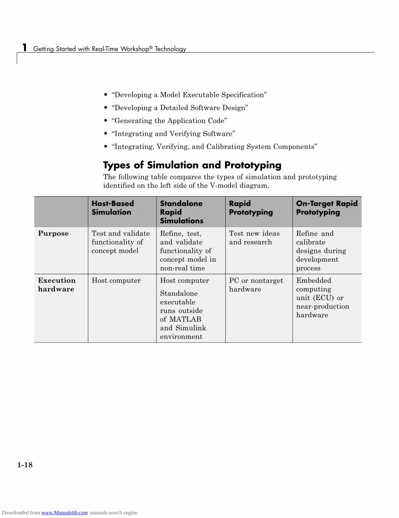
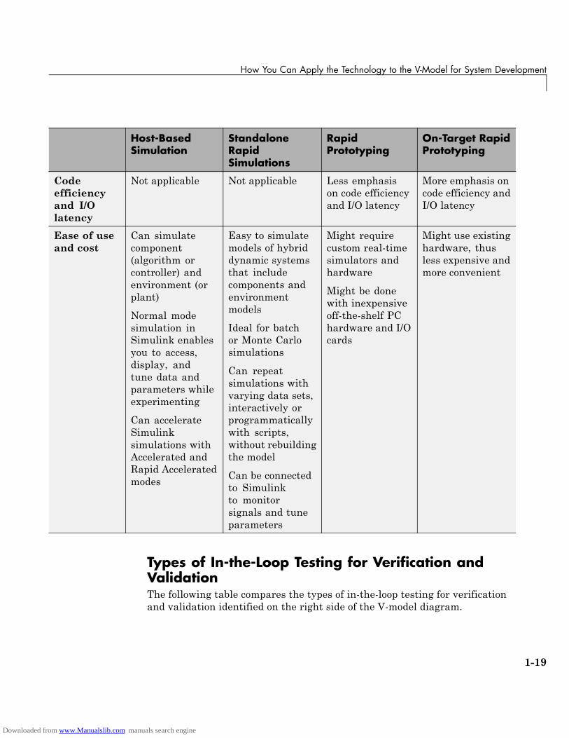
Types of Simulation and PrototypingThe following table compares the types of simulation and prototypingidentified on the left side of the V-model diagram.
Host-BasedSimulation
StandaloneRapidSimulations
RapidPrototyping
On-Target RapidPrototyping
Purpose Test and validatefunctionality ofconcept model
Refine, test,and validatefunctionality ofconcept model innon-real time
Test new ideasand research
Refine andcalibratedesigns duringdevelopmentprocess
Executionhardware
Host computer Host computer
Standaloneexecutableruns outsideof MATLABand Simulinkenvironment
PC or nontargethardware
Embeddedcomputingunit (ECU) ornear-productionhardware
1-18
Downloaded from www.Manualslib.com manuals search engine
How You Can Apply the Technology to the V-Model for System Development
Host-BasedSimulation
StandaloneRapidSimulations
RapidPrototyping
On-Target RapidPrototyping
Codeefficiencyand I/Olatency
Not applicable Not applicable Less emphasison code efficiencyand I/O latency
More emphasis oncode efficiency andI/O latency
Ease of useand cost
Can simulatecomponent(algorithm orcontroller) andenvironment (orplant)
Normal modesimulation inSimulink enablesyou to access,display, andtune data andparameters whileexperimenting
Can accelerateSimulinksimulations withAccelerated andRapid Acceleratedmodes
Easy to simulatemodels of hybriddynamic systemsthat includecomponents andenvironmentmodels
Ideal for batchor Monte Carlosimulations
Can repeatsimulations withvarying data sets,interactively orprogrammaticallywith scripts,without rebuildingthe model
Can be connectedto Simulinkto monitorsignals and tuneparameters
Might requirecustom real-timesimulators andhardware
Might be donewith inexpensiveoff-the-shelf PChardware and I/Ocards
Might use existinghardware, thusless expensive andmore convenient
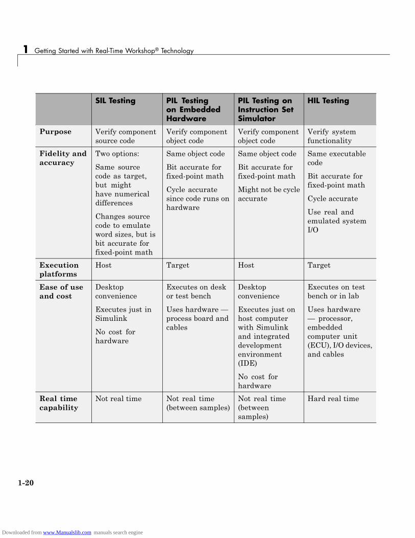
Types of In-the-Loop Testing for Verification andValidationThe following table compares the types of in-the-loop testing for verificationand validation identified on the right side of the V-model diagram.
1-19
Downloaded from www.Manualslib.com manuals search engine
1 Getting Started with Real-Time Workshop® Technology
SIL Testing PIL Testingon EmbeddedHardware
PIL Testing onInstruction SetSimulator
HIL Testing
Purpose Verify componentsource code
Verify componentobject code
Verify componentobject code
Verify systemfunctionality
Fidelity andaccuracy
Two options:
Same sourcecode as target,but mighthave numericaldifferences
Changes sourcecode to emulateword sizes, but isbit accurate forfixed-point math
Same object code
Bit accurate forfixed-point math
Cycle accuratesince code runs onhardware
Same object code
Bit accurate forfixed-point math
Might not be cycleaccurate
Same executablecode
Bit accurate forfixed-point math
Cycle accurate
Use real andemulated systemI/O
Executionplatforms
Host Target Host Target
Ease of useand cost
Desktopconvenience
Executes just inSimulink
No cost forhardware
Executes on deskor test bench
Uses hardware —process board andcables
Desktopconvenience
Executes just onhost computerwith Simulinkand integrateddevelopmentenvironment(IDE)
No cost forhardware
Executes on testbench or in lab
Uses hardware— processor,embeddedcomputer unit(ECU), I/O devices,and cables
Real timecapability
Not real time Not real time(between samples)
Not real time(betweensamples)
Hard real time
1-20
Downloaded from www.Manualslib.com manuals search engine

2
How to Develop anApplication UsingReal-Time WorkshopSoftware
• “Workflow for Developing Applications Using Real-Time WorkshopSoftware” on page 2-2
• “Mapping Application Requirements to Configuration Options” on page 2-4
• “Adjusting Configuration Settings” on page 2-6
• “Running the Model Advisor” on page 2-7
• “Generating Code” on page 2-10
• “Building an Executable Program” on page 2-11
• “Verifying the Executable Program” on page 2-14
• “Naming and Saving the Configuration Set” on page 2-15
• “Documenting the Project” on page 2-17
Downloaded from www.Manualslib.com manuals search engine
2 How to Develop an Application Using Real-Time Workshop® Software
Workflow for Developing Applications Using Real-TimeWorkshop Software
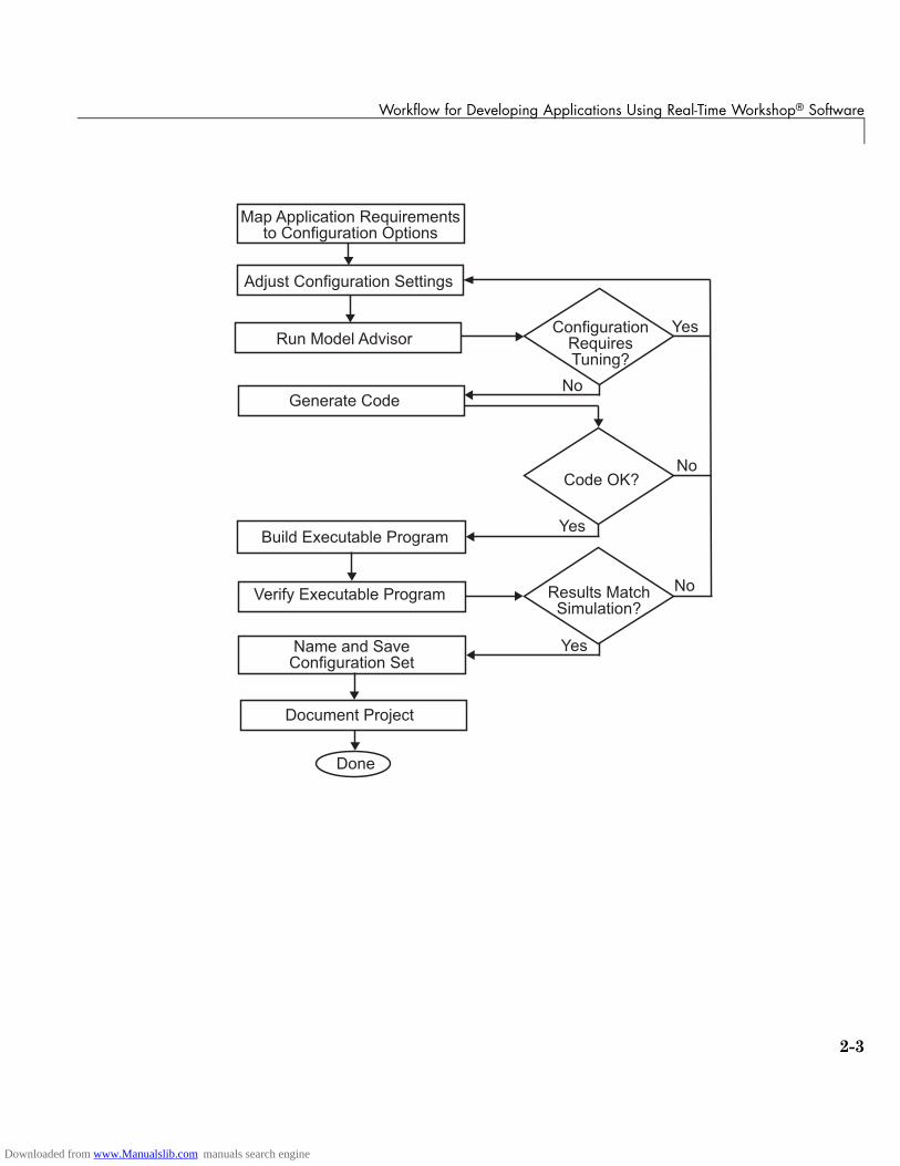
The typical workflow for applying the Real-Time Workshop software to theapplication development process involves the following steps:
1 Map your application requirements to available configuration options.
2 Adjust configuration options as necessary.
3 Run the Model Advisor tool.
4 If necessary, tune configuration options based on the Model Advisor report.
5 Generate code for your model.
6 Repeat steps 2 to 5, if necessary.
7 Build an executable program image.
8 Verify that the generated program produces results that are equivalentto those of your model simulation.
9 Save the configuration, and alternative ones with the model.
10 Use Simulink Report Generator to automatically document the project.
The following figure shows these steps in a flow diagram. Sections followingthe figure discuss the steps in more detail.
2-2
Downloaded from www.Manualslib.com manuals search engine
Workflow for Developing Applications Using Real-Time Workshop® Software
�������������� �������������������������������
�������������������������
����������������
������������
����������� ���!������
"����#������ ���!������
$���������������������������
%������!����
������������ �������&�����'
������('
��������)���������'
%���
*��
$�
*��
$�
$�
*��
2-3
Downloaded from www.Manualslib.com manuals search engine

2 How to Develop an Application Using Real-Time Workshop® Software
Mapping Application Requirements to ConfigurationOptions
The first step in applying the Real-Time Workshop software to the applicationdevelopment process is to consider how your application requirements,particularly with respect to debugging, traceability, efficiency, and safety,map to code generation options available through the Simulink ConfigurationParameters dialog box. The following screen display shows the Real-TimeWorkshop pane of the Configuration Parameters dialog box.
Parameters that you set in the various panes of the Configuration Parametersdialog box affect the behavior of a model in simulation and the code generatedfor the model. The Real-Time Workshop software automatically adjusts theavailable configuration parameters and their default settings based on yourtarget selection. For example, the preceding dialog box display shows defaultsettings for the generic real-time (GRT) target. However, you should becomefamiliar with the various parameters and be prepared to adjust settings tooptimize a configuration for your application.
As you review the parameters, consider questions such as the following:
• What settings will help you debug your application?
• What is the highest priority for your application — efficiency, traceability,extra safety precaution, or some other criterion?
• What is the second highest priority?
2-4
Downloaded from www.Manualslib.com manuals search engine

Mapping Application Requirements to Configuration Options
• Can the priority at the start of the project differ from the priority requiredfor the end? What tradeoffs can be made?
Once you have answered these questions, you can either:
• Use the Code Generation Advisor to identify changes to model constructsand settings that improve the generated code. For more information, see“Configuring Code Generation Objectives” in the Real-Time WorkshopUser’s Guide.
• Review “Recommended Settings Summary”, which summarizes the impactof each configuration option on efficiency, traceability, safety precautions,and debugging, and indicates the default (factory) configuration settings forthe GRT target. For additional details, click the links in the ConfigurationParameter column.
Note
• Review the “Recommended Settings Summary” to see the settings the CodeGeneration Advisor recommends.
• If you use a specific embedded target, a Stateflow target, or fixed-pointblocks, consider the mapping of many other configuration parameters. Fordetails, see the documentation specific to your target environment.
2-5
Downloaded from www.Manualslib.com manuals search engine
2 How to Develop an Application Using Real-Time Workshop® Software
Adjusting Configuration SettingsOnce you have mapped your application requirements to appropriateconfiguration parameter settings, adjust the settings accordingly. Usingthe Default column in “Mapping Application Requirements to the SolverPane”, identify the configuration parameters you need to modify. Then,open the Configuration Parameters dialog box or Model Explorer and makethe necessary adjustments.
Tutorials in Chapter 3, “Working with the Real-Time Workshop Software”guide you through exercises that modify configuration parameter settings.For more information on setting configuration parameters for code generation,see “Preparing Models for Code Generation”“Building Executables” in theReal-Time Workshop documentation. For descriptions of parameters specificto the Real-Time Workshop product, see “Configuration Parameters forSimulink Models” or “Configuration Parameters for Embedded MATLABCoder” in the Real-Time Workshop reference documentation.
Note In addition to using the Configuration Parameters dialog box, you canuse get_param and set_param to individually access most configurationparameters both interactively and in scripts. The configuration parametersyou can get and set are listed in the “Parameter Reference” in the Real-TimeWorkshop documentation.
2-6
Downloaded from www.Manualslib.com manuals search engine
Running the Model Advisor
Running the Model AdvisorBefore you generate code, it is good practice to run the Model Advisor. Basedon a list of options you select, this tool analyzes your model and its parametersettings, and generates results that list findings with advice on how to correctand improve the model and its configuration.
One way of starting the Model Advisor is to select Tools > Model Advisor inyour model window. A new window appears listing specific diagnostics youcan selectively enable or disable. Some examples of the diagnostics follow:
• Identify blocks that generate expensive saturation and rounding code
• Check optimization settings
• Identify questionable software environment specifications
2-7
Downloaded from www.Manualslib.com manuals search engine
2 How to Develop an Application Using Real-Time Workshop® Software
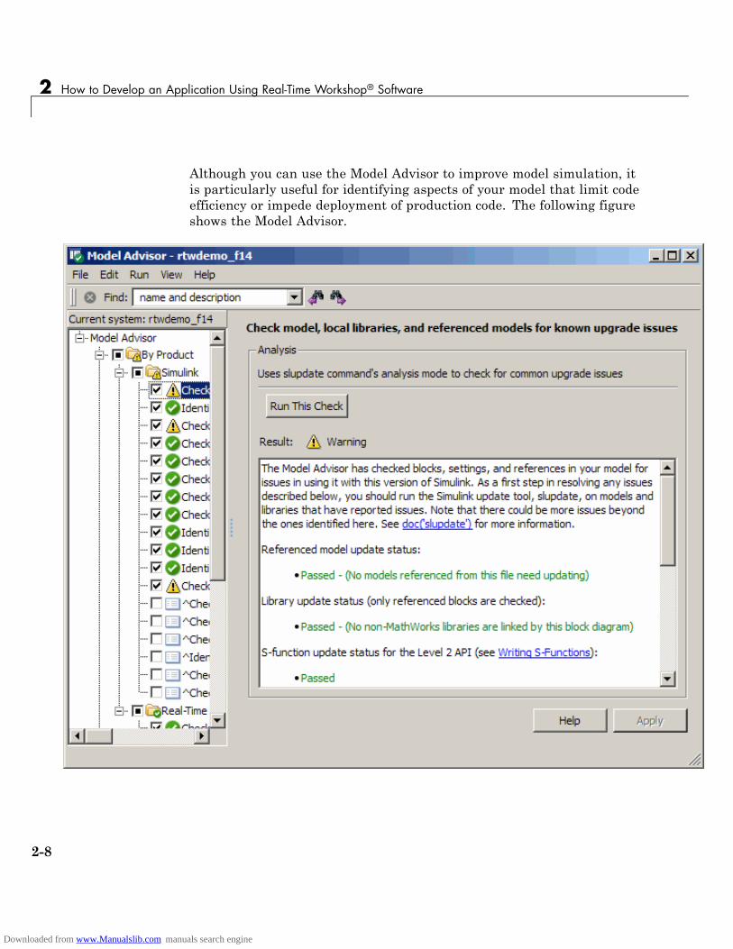
Although you can use the Model Advisor to improve model simulation, itis particularly useful for identifying aspects of your model that limit codeefficiency or impede deployment of production code. The following figureshows the Model Advisor.
2-8
Downloaded from www.Manualslib.com manuals search engine

Running the Model Advisor
For more information on using the Model Advisor, see “Getting AdviceAbout Optimizing Models for Code Generation” in the Real-Time Workshopdocumentation.
2-9
Downloaded from www.Manualslib.com manuals search engine
2 How to Develop an Application Using Real-Time Workshop® Software
Generating CodeAfter fine-tuning your model and its parameter settings, you are ready togenerate code. Typically, the first time through the process of applyingReal-Time Workshop software for an application, you want to generate codewithout going on to compile and link it into an executable program. Somereasons for doing this include the following:
• You want to inspect the generated code. Is the Real-Time Workshop codegenerator creating what you expect?
• You need to integrate custom handwritten code.
• You want to experiment with configuration option settings.
You specify code generation only by selecting the Generate code onlycheck box available on the Real-Time Workshop pane of the ConfigurationParameters dialog box (thus changing the label of the Build button toGenerate code). The Real-Time Workshop code generator responds byanalyzing the block diagram that represents your model, generating C code,and placing the resulting files in a build directory within your currentworking directory.
After generating the code, inspect it. Is it what you expected? If not,determine what model and configuration changes you need to make, rerunthe Model Advisor, and regenerate the code. When you are satisfied with thegenerated code, build an executable program image, as explained in “Buildingan Executable Program” on page 2-11.
For details on the Generate code only option, see “Generate code only” inthe Real-Time Workshop documentation.
2-10
Downloaded from www.Manualslib.com manuals search engine
Building an Executable Program
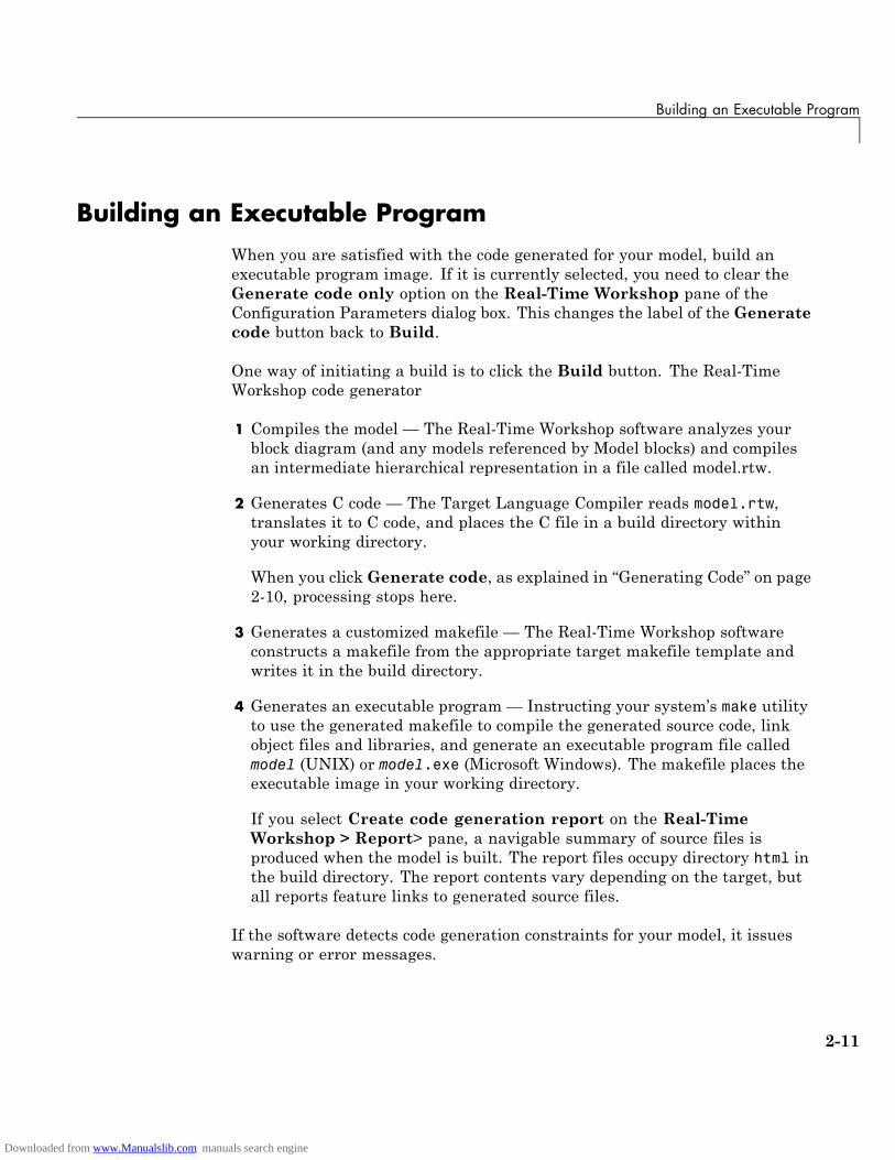
Building an Executable ProgramWhen you are satisfied with the code generated for your model, build anexecutable program image. If it is currently selected, you need to clear theGenerate code only option on the Real-Time Workshop pane of theConfiguration Parameters dialog box. This changes the label of the Generatecode button back to Build.
One way of initiating a build is to click the Build button. The Real-TimeWorkshop code generator
1 Compiles the model — The Real-Time Workshop software analyzes yourblock diagram (and any models referenced by Model blocks) and compilesan intermediate hierarchical representation in a file called model.rtw.
2 Generates C code — The Target Language Compiler reads model.rtw,translates it to C code, and places the C file in a build directory withinyour working directory.
When you click Generate code, as explained in “Generating Code” on page2-10, processing stops here.
3 Generates a customized makefile — The Real-Time Workshop softwareconstructs a makefile from the appropriate target makefile template andwrites it in the build directory.
4 Generates an executable program — Instructing your system’s make utilityto use the generated makefile to compile the generated source code, linkobject files and libraries, and generate an executable program file calledmodel (UNIX) or model.exe (Microsoft Windows). The makefile places theexecutable image in your working directory.
If you select Create code generation report on the Real-TimeWorkshop > Report> pane, a navigable summary of source files isproduced when the model is built. The report files occupy directory html inthe build directory. The report contents vary depending on the target, butall reports feature links to generated source files.
If the software detects code generation constraints for your model, it issueswarning or error messages.
2-11
Downloaded from www.Manualslib.com manuals search engine
2 How to Develop an Application Using Real-Time Workshop® Software
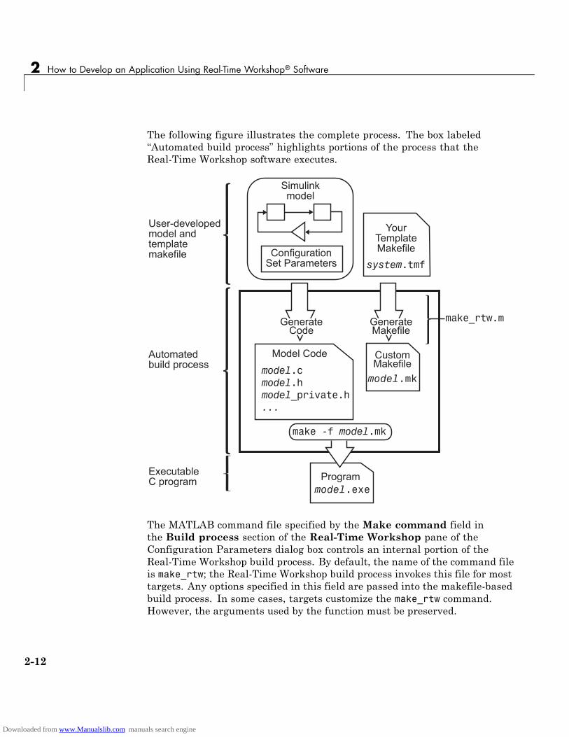
The following figure illustrates the complete process. The box labeled“Automated build process” highlights portions of the process that theReal-Time Workshop software executes.
�������+�����
���������������!��������
,���-��������������������������+�����
*���&��������+�����
����������
������� �����������
����� �����������
�����������
���������+�����
��������
����� ���������
�������+�����
�������
��������!������
����������
������������������������
The MATLAB command file specified by the Make command field inthe Build process section of the Real-Time Workshop pane of theConfiguration Parameters dialog box controls an internal portion of theReal-Time Workshop build process. By default, the name of the command fileis make_rtw; the Real-Time Workshop build process invokes this file for mosttargets. Any options specified in this field are passed into the makefile-basedbuild process. In some cases, targets customize the make_rtw command.However, the arguments used by the function must be preserved.
2-12
Downloaded from www.Manualslib.com manuals search engine

Building an Executable Program
Although the command may work for a stand-alone model, use of themake_rtw command at the command line can be error prone. For example, ifyou have multiple models open, you need to check whether
• The current subsystem, found by entering gcs in the MATLAB commandwindow, contains the model you want to build.
• TheMake command specified in the Configuration Parameters dialog boxfor the target environment is make_rtw.
• The model includes Model blocks. Models containing Model blocks do notbuild by using make_rtw directly.
To build (or generate code for) a model from the MATLAB Command Window,use one of the following rtwbuild commands, where model is the name ofthe model:
rtwbuild modelrtwbuild('model')
2-13
Downloaded from www.Manualslib.com manuals search engine
2 How to Develop an Application Using Real-Time Workshop® Software
Verifying the Executable ProgramOnce you have an executable image, run the image and compare the results tothe results of your model’s simulation. You can do this by
1 Logging output data produced by simulation runs
2 Logging output data produced by executable program runs
3 Comparing the results of the simulation and executable program runs
Does the output match? Are you able to explain any differences? Do you needto eliminate any differences? At this point, it might be necessary to revisitand possibly fine-tune your block and configuration parameter settings.
For an example, see “Code Verification” on page 3-27.
2-14
Downloaded from www.Manualslib.com manuals search engine
Naming and Saving the Configuration Set
Naming and Saving the Configuration SetWhen you close a model, you should save it to preserve your configurationsettings (unless you regard your recent changes as dispensable). If you wantto maintain several alternative configurations for a model (e.g., GRT andRapid Simulation targets, inline parameters on/off, different solvers, etc.), youcan set up a configuration set for each set of configuration parameters andgive it an identifying name. You can do this easily in Model Explorer.
To name and save a configuration,
1 Open Model Explorer by selecting Model Explorer from the model’sView menu.
2 In the Model Hierarchy pane, click the + sign preceding the model nameto reveal its components.
3 Click the Configuration (active) node under the model name.
The Configuration Parameters dialog box appears in the right pane.
4 In the Configuration Parameters pane, type a name you want to givethe current configuration in the Name field.
5 Click Apply. The name of the active configuration in the ModelHierarchy pane changes to the name you typed.
6 Save the model.
Adding and Copying Configuration SetsYou can save the model with more than one configuration so that youcan instantly reconfigure it at a later time. To do this, copy the activeconfiguration to a new one, or add a new one, then modify and name thenew configuration, as follows:
1 Open Model Explorer by selecting Model Explorer from the model’sView menu.
2 In the Model Hierarchy pane, click the + sign preceding the model nameto reveal its components.
2-15
Downloaded from www.Manualslib.com manuals search engine
2 How to Develop an Application Using Real-Time Workshop® Software
3 To add a new configuration set, while the model is selected in the ModelHierarchy pane, select Configuration Set from the Add menu, or clickthe yellow gear icon on the toolbar:
A new configuration set named Configuration appears in the ModelHierarchy pane.
4 To copy an existing configuration set, right-click its name in the ModelHierarchy pane and drag it to the + sign in front of the model name.
A new configuration set with a numeral (e.g., 1) appended to its nameappears lower in the Model Hierarchy pane.
5 If desired, rename the new configuration by right-clicking it, selectingProperties, and typing the new name in the Name field on theConfiguration Parameters dialog box that appears. Then click the Applybutton.
6 Make the new configuration the active one by right-clicking it in theModelHierarchy pane and selecting Activate from the context menu.
The content of the Is Active field in the right pane changes from no to yes.
7 Save the model.
2-16
Downloaded from www.Manualslib.com manuals search engine

Documenting the Project
Documenting the ProjectConsider documenting the design and implementation details of your projectto facilitate
• Project verification and validation
• Collaboration with other individuals or teams, particularly if dependenciesexist
• Archiving the project for future reference
One way of documenting a Real-Time Workshop code generation projectis to use the Simulink Report Generator software. You can generate acomprehensive Rich Text Format (RTF), Extensible Markup Language (XML),or Hypertext Markup Language (HTML) report that includes the followinginformation:
• Model name and version
• Real-Time Workshop product version
• Date and time the code generator created the code
• List of generated source and header (include) files
• Optimization and Real-Time Workshop target selection and build processconfiguration settings
• Mapping of subsystem numbers to subsystem labels
• Listings of generated and custom code for the model
To get started with generating a code generation report, see the demortwdemo_codegenrpt and tutorial “Documenting a Code Generation Project”on page 3-72. For details on using the Report Generator, see the SimulinkReport Generator User’s Guide.
2-17
Downloaded from www.Manualslib.com manuals search engine

2 How to Develop an Application Using Real-Time Workshop® Software
2-18
Downloaded from www.Manualslib.com manuals search engine

3
Working with the Real-TimeWorkshop Software
This chapter provides hands-on tutorials that help you get started generatingcode with the Real-Time Workshop software, as quickly as possible. Itincludes the following topics:
• “Demonstration Model: rtwdemo_f14” on page 3-3
• “Building a Generic Real-Time Program” on page 3-4
• “Data Logging” on page 3-18
• “Code Verification” on page 3-27
• “First Look at Generated Code” on page 3-33
• “Working with External Mode Using GRT” on page 3-47
• “Generating Code for a Referenced Model” on page 3-60
• “Documenting a Code Generation Project” on page 3-72
To get the maximum benefit from this book, The MathWorks recommendsthat you study and work all the tutorials, in the order presented.
These tutorials assume basic familiarity with the MATLAB and Simulinkproducts. You should also read Chapter 2, “How to Develop an ApplicationUsing Real-Time Workshop Software”, before proceeding.
The procedures for building, running, and testing your programs are almostidentical in UNIX and PC environments. The discussion notes differenceswhere applicable.
Downloaded from www.Manualslib.com manuals search engine

3 Working with the Real-Time Workshop® Software
Make sure that a MATLAB compatible C compiler is installed on your systembefore proceeding with these tutorials. For details on supported compilerversions, see
http://www.mathworks.com/support/compilers/current_release
3-2
Downloaded from www.Manualslib.com manuals search engine
Demonstration Model: rtwdemo_f14
Demonstration Model: rtwdemo_f14The first three tutorials use a demonstration Simulink model,rtwdemo_f14.mdl, from the directory:
matlabroot/toolbox/rtw/rtwdemos/
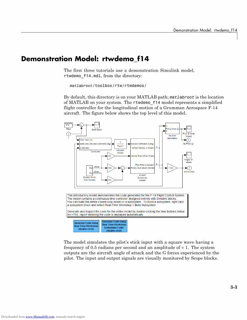
By default, this directory is on your MATLAB path; matlabroot is the locationof MATLAB on your system. The rtwdemo_f14 model represents a simplifiedflight controller for the longitudinal motion of a Grumman Aerospace F-14aircraft. The figure below shows the top level of this model.
The model simulates the pilot’s stick input with a square wave having afrequency of 0.5 radians per second and an amplitude of ± 1. The systemoutputs are the aircraft angle of attack and the G forces experienced by thepilot. The input and output signals are visually monitored by Scope blocks.
3-3
Downloaded from www.Manualslib.com manuals search engine
3 Working with the Real-Time Workshop® Software
Building a Generic Real-Time Program
In this section...
“Tutorial Overview” on page 3-4
“Working and Build Directories” on page 3-4
“Setting Program Parameters” on page 3-5
“Selecting the Target Configuration” on page 3-7
“Building and Running the Program” on page 3-13
“Contents of the Build Directory” on page 3-15
Tutorial OverviewThis tutorial walks through the process of generating C code and building anexecutable program from the demonstration model. The resulting stand-aloneprogram runs on your workstation, independent of external timing and events.
Working and Build DirectoriesIt is convenient to work with a local copy of the rtwdemo_f14 model, stored inits own directory, f14example. Set up your working directory as follows:
1 In the MATLAB Current Folder browser, navigate to a directory whereyou have write access.
2 Create the working directory from the MATLAB command line by typing:
mkdir f14example
3 Make f14example your working directory:
cd f14example
4 Open the rtwdemo_f14 model:
rtwdemo_f14
The model appears in the Simulink window.
3-4
Downloaded from www.Manualslib.com manuals search engine
Building a Generic Real-Time Program
5 In the model window, choose File > Save As. Navigate to your workingdirectory, f14example. Save a copy of the rtwdemo_f14 model asf14rtw.mdl.
During code generation, the Real-Time Workshop software creates a builddirectory within your working directory. The build directory name ismodel_target_rtw, derived from the name of the source model and thechosen target. The build directory stores generated source code and other filescreated during the build process. You examine the build directory contents atthe end of this tutorial.
Note When a model contains Model blocks (which enable one Simulink modelto include others), special project directories are created in your workingdirectory to organize code for referenced models. Project directories existalongside of Real-Time Workshop build directories, and are always namedslprj. “Generating Code for a Referenced Model” on page 3-60 describesnavigating project directory structures in Model Explorer.
Setting Program ParametersTo generate code correctly from the f14rtw model, you must change some ofthe simulation parameters. In particular, note that generic real-time (GRT)and most other targets require that the model specify a fixed-step solver.
Note The Real-Time Workshop software can generate code for models usingvariable-step solvers for rapid simulation (rsim) and S-function targets only.
To set parameters, use the Model Explorer as follows:
1 Open Model Explorer by selecting Model Explorer from the model’sView menu.
2 In the Model Hierarchy pane, click the + sign preceding the model nameto reveal its components.
3 Click Configuration (Active) in the left pane.
3-5
Downloaded from www.Manualslib.com manuals search engine
3 Working with the Real-Time Workshop® Software
4 Click Solver in the center pane. The Solver pane appears at the right.
5 Enter the following parameter values on the Solver pane (some mayalready be set):
• Start time: 0.0
• Stop time: 60
• Type: Fixed-step
• Solver: ode5 (Dormand-Prince)
• Fixed step size (fundamental sample time): 0.1
• Tasking mode for periodic sample times: SingleTasking
The Solver pane with the modified parameter settings is shown below.Note the tan background color of the controls you just changed. The coloralso appears on fields that were set automatically by your choices in otherfields. Use this visual feedback to verify that what you set is what youintended. When you apply your changes, the background color revertsto white.
3-6
Downloaded from www.Manualslib.com manuals search engine

Building a Generic Real-Time Program
6 Click Apply to register your changes.
7 Save the model. Simulation parameters persist with the model, for use infuture sessions.
Selecting the Target Configuration
Note Some of the steps in this section do not require you to make changes.They are included to help you familiarize yourself with the Real-TimeWorkshop user interface. As you step through the dialog boxes, place themouse pointer on any item of interest to see a tooltip describing its function.
To specify the desired target configuration, you choose a system target file, atemplate makefile, and a make command.
3-7
Downloaded from www.Manualslib.com manuals search engine

3 Working with the Real-Time Workshop® Software
In these tutorials (and in most applications), you do not need to specify theseparameters individually. Here, you use the ready-to-run generic real-timetarget (GRT) configuration. The GRT target is designed to build a stand-aloneexecutable program that runs on your workstation.
To select the GRT target via the Model Explorer:
1 With the f14rtw model open, open Model Explorer by selecting ModelExplorer from the model’s View menu.
2 In the Model Hierarchy pane, click the + sign preceding the model nameto reveal its components.
3 Click Configuration (Active) in the left pane.
4 Click Real-Time Workshop in the center pane. The Real-TimeWorkshop pane appears at the right. This pane has several tabs.
5 Click the General tab to activate the pane that controls target selection.
3-8
Downloaded from www.Manualslib.com manuals search engine
Building a Generic Real-Time Program
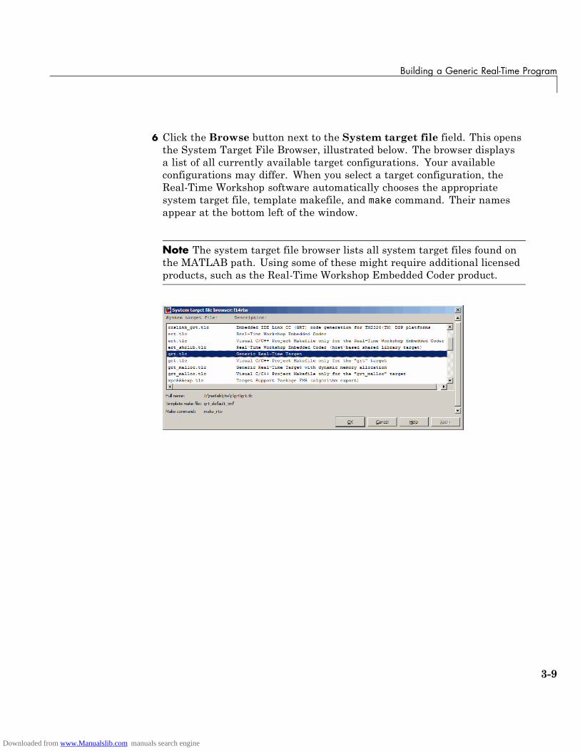
6 Click the Browse button next to the System target file field. This opensthe System Target File Browser, illustrated below. The browser displaysa list of all currently available target configurations. Your availableconfigurations may differ. When you select a target configuration, theReal-Time Workshop software automatically chooses the appropriatesystem target file, template makefile, and make command. Their namesappear at the bottom left of the window.
Note The system target file browser lists all system target files found onthe MATLAB path. Using some of these might require additional licensedproducts, such as the Real-Time Workshop Embedded Coder product.
3-9
Downloaded from www.Manualslib.com manuals search engine

3 Working with the Real-Time Workshop® Software
7 From the list of available configurations, select Generic Real-TimeTarget (as shown above) and then click OK.
The Real-Time Workshop pane displays the correct system targetfile (grt.tlc), make command (make_rtw), and template makefile(grt_default_tmf), as shown below:
3-10
Downloaded from www.Manualslib.com manuals search engine

Building a Generic Real-Time Program
8 Select the Debug tab of the Real-Time Workshop pane. The optionsdisplayed here control build verbosity and debugging support, and arecommon to all target configurations. Make sure that all options are setto their defaults, as shown below.
3-11
Downloaded from www.Manualslib.com manuals search engine

3 Working with the Real-Time Workshop® Software
9 Select the Symbols tab of the Real-Time Workshop pane. The options onthis pane control the look and feel of generated code.
3-12
Downloaded from www.Manualslib.com manuals search engine

Building a Generic Real-Time Program
10 Select the Comments tab of the Real-Time Workshop pane. The optionsdisplayed here control the types of comments included in generated code.Make sure that all options are set to their defaults, as shown below.
11 Make sure that the Generate code only check box at the bottom of thepane is cleared.
12 Save the model.
Building and Running the ProgramThe Real-Time Workshop build process generates C code from the model,and then compiles and links the generated program to create an executableimage. To build and run the program,
3-13
Downloaded from www.Manualslib.com manuals search engine
3 Working with the Real-Time Workshop® Software
1 With the f14rtw model open, go to the Model Explorer window. In theReal-Time Workshop pane, select the General tab, then click the Buildbutton to start the build process.
A number of messages concerning code generation and compilation appearin the MATLAB Command Window. The initial message is
### Starting Real-Time Workshop build procedure for model: f14rtw
The contents of many of the succeeding messages depends on your compilerand operating system. The final message is
### Successful completion of Real-Time Workshop build procedurefor model: f14rtw
The working directory now contains an executable, f14rtw.exe (MicrosoftWindows platforms) or f14rtw (UNIX platforms). In addition, theReal-Time Workshop build process has created a project directory, slprj,and a build directory, f14rtw_grt_rtw, in your working directory.
Note The Real-Time Workshop build process displays a code generationreport after generating the code for the f14rtw model. The tutorial “FirstLook at Generated Code” on page 3-33 provides more information abouthow to create and use a code generation report.
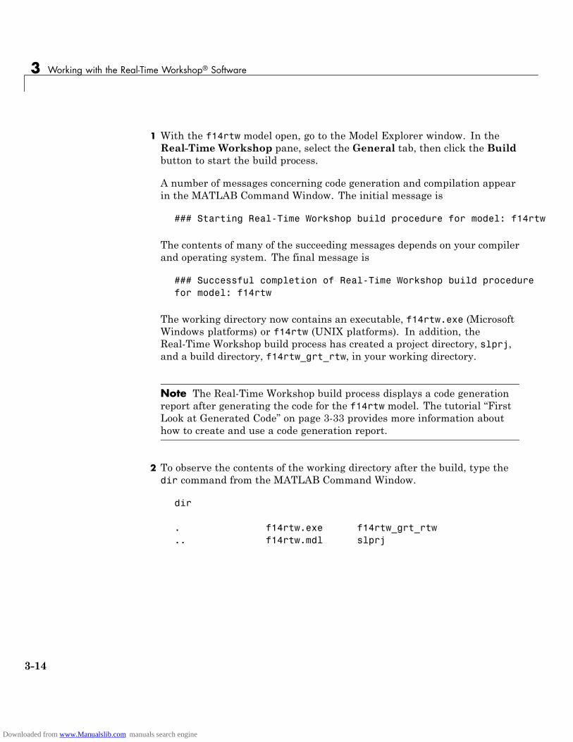
2 To observe the contents of the working directory after the build, type thedir command from the MATLAB Command Window.
dir
. f14rtw.exe f14rtw_grt_rtw
.. f14rtw.mdl slprj
3-14
Downloaded from www.Manualslib.com manuals search engine
Building a Generic Real-Time Program
3 To run the executable from the Command Window, type
!f14rtw
The ! character passes the command that follows it to the operating system,which runs the stand-alone f14rtw program.
The program produces one line of output in the Command Window:
**starting the model**
No data is output.
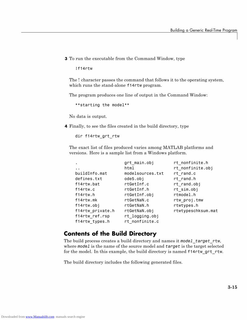
4 Finally, to see the files created in the build directory, type
dir f14rtw_grt_rtw
The exact list of files produced varies among MATLAB platforms andversions. Here is a sample list from a Windows platform.
. grt_main.obj rt_nonfinite.h
.. html rt_nonfinite.objbuildInfo.mat modelsources.txt rt_rand.cdefines.txt ode5.obj rt_rand.hf14rtw.bat rtGetInf.c rt_rand.objf14rtw.c rtGetInf.h rt_sim.objf14rtw.h rtGetInf.obj rtmodel.hf14rtw.mk rtGetNaN.c rtw_proj.tmwf14rtw.obj rtGetNaN.h rtwtypes.hf14rtw_private.h rtGetNaN.obj rtwtypeschksum.matf14rtw_ref.rsp rt_logging.objf14rtw_types.h rt_nonfinite.c
Contents of the Build DirectoryThe build process creates a build directory and names it model_target_rtw,where model is the name of the source model and target is the target selectedfor the model. In this example, the build directory is named f14rtw_grt_rtw.
The build directory includes the following generated files.
3-15
Downloaded from www.Manualslib.com manuals search engine

3 Working with the Real-Time Workshop® Software
Note The code generation report you created for the f14rtw model in theprevious section displays a link for each file listed below, which you can clickto explore the file contents.
File Description
f14rtw.c Standalone C code that implements the model
rt_nonfinite.crtGetInf.crtGetNaN.c
Functions to initialize nonfinite types (Inf,NaN, and -Inf)
rt_rand.c Random functions, included only if needed bythe application
f14rtw.h An include header file containing definitions ofparameters and state variables
f14rtw_private.h Header file containing common includedefinitions
f14rtw_types.h Forward declarations of data types used in thecode
rt_nonfinite.hrtGetInf.hrtGetNaN.h
Provides support for nonfinite numbers in thegenerated code, dynamically generates Inf,NaN, and -Inf as needed
rt_rand.h Imported declarations for random functions,included only if needed by the application
rtmodel.h Master header file for including generated codein the static main program (its name neverchanges, and it simply includes f14rtw.h)
rtwtypes.h Static include file for Simulink simstruct datatypes; some embedded targets tailor this file toreduce overhead, but GRT does not
The build directory contains other files used in the build process, most ofwhich you can disregard for the present:
• f14rtw.mk— Makefile generated from a template for the GRT target
3-16
Downloaded from www.Manualslib.com manuals search engine
Building a Generic Real-Time Program
• Object (.obj) files
• f14rtw.bat — Batch control file
• rtw_proj.tmw — Marker file
• buildInfo.mat — Build information for relocating generated code toanother development environment
• defines.txt— Preprocessor defines required for compiling the generatedcode
• f14rtw_ref.rsp — Data to include as command-line arguments to mex(Windows systems only)
The build directory also contains a subdirectory, html, which contains thefiles that make up the code generation report. For more information aboutthe code generation report, see the tutorial “First Look at Generated Code”on page 3-33.
3-17
Downloaded from www.Manualslib.com manuals search engine
3 Working with the Real-Time Workshop® Software
Data Logging
In this section...
“Tutorial Overview” on page 3-18
“Data Logging During Simulation” on page 3-19
“Data Logging from Generated Code” on page 3-22
Tutorial OverviewReal-Time Workshop MAT-file data logging facility enables a generatedprogram to save system states, outputs, and simulation time at each modelexecution time step. The data is written to a MAT-file, named (by default)model.mat, where model is the name of your model. In this tutorial, datagenerated by the model f14rtw.mdl is logged to the file f14rtw.mat. Referto “Building a Generic Real-Time Program” on page 3-4 for instructions onsetting up f14rtw.mdl in a working directory if you have not done so already.
To configure data logging, click Data Import/Export in the center paneof the Model Explorer. The process is the same as configuring a Simulinkmodel to save output to the MATLAB workspace. For each workspace returnvariable you define and enable, the Real-Time Workshop software definesa parallel MAT-file variable. For example, if you save simulation time tothe variable tout, your generated program logs the same data to a variablenamed rt_tout. You can change the prefix rt_ to a suffix (_rt), or eliminateit entirely. You do this by selecting Real-Time Workshop in the center paneof the Model Explorer, then clicking the Interface tab.
Note Simulink lets you log signal data from anywhere in a model via the Logsignal data option in the Signal Properties dialog box (accessed via contextmenu by right-clicking signal lines). The Real-Time Workshop softwaredoes not use this method of signal logging in generated code. To log signalsin generated code, you must either use the Data Import/Export optionsdescribed below or include To File or To Workspace blocks in your model.
In this tutorial, you modify the f14rtw model so that the generated programsaves the simulation time and system outputs to the file f14rtw.mat. Then
3-18
Downloaded from www.Manualslib.com manuals search engine

Data Logging
you load the data into the MATLAB workspace and plot simulation timeagainst one of the outputs. The f14rtw model should be open and configuredas it was at the end of the previous tutorial.
Data Logging During SimulationTo use the data logging feature:
1 Open Model Explorer by selecting Model Explorer from the model’sView menu.
2 In the Model Hierarchy pane, click the + sign preceding the model nameto reveal its components.
3 Click Configuration (Active) in the left pane.
4 Click Data Import/Export in the center pane. The Data Import/Exportpane appears at the right. Its Save to workspace section lets you specifywhich outport data is to be saved to the workspace and what variablenames to use for it.
5 Select the Time option. This tells Simulink to save time step data duringsimulation as a variable named tout. You can enter a different name todistinguish different simulation runs (for example using different stepsizes), but take the default for this tutorial. Selecting Time enables theReal-Time Workshop code generator to create code that logs the simulationtime to a MAT-file.
6 Select the Output option. This tells Simulink to save output signal dataduring simulation as a variable named yout. Selecting Output enablesthe Real-Time Workshop code generator to create code that logs the rootOutput blocks (Angle of Attack and Pilot G Force) to a MAT-file.
Note The sort order of the yout array is based on the port number of theOutport blocks, starting with 1. Angle of Attack and Pilot G Force arelogged to yout(:,1) and yout(:,2), respectively.
3-19
Downloaded from www.Manualslib.com manuals search engine
3 Working with the Real-Time Workshop® Software
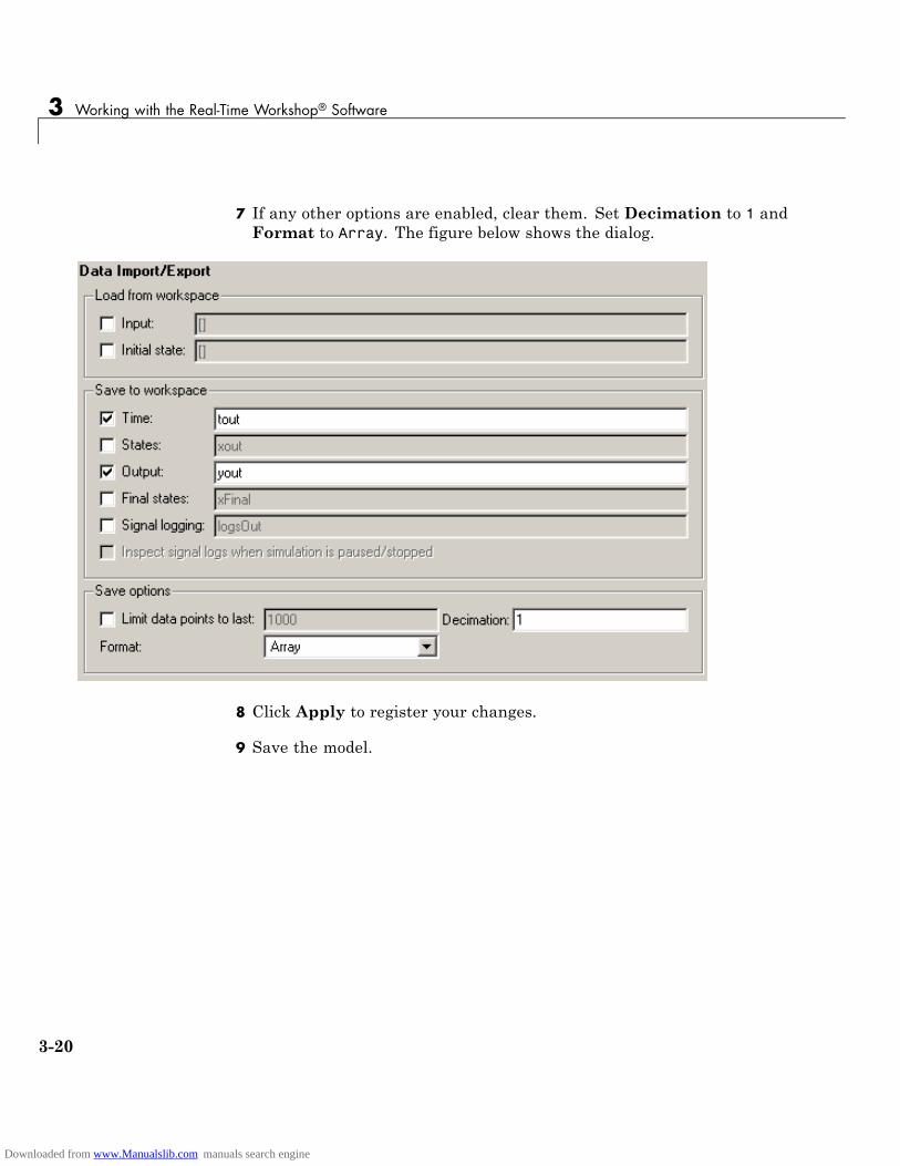
7 If any other options are enabled, clear them. Set Decimation to 1 andFormat to Array. The figure below shows the dialog.
8 Click Apply to register your changes.
9 Save the model.
3-20
Downloaded from www.Manualslib.com manuals search engine

Data Logging
10 Open the Pilot G Force Scope block of the model, then run the model bychoosing Simulation > Start in the model window. The resulting Pilot GForce scope display is shown below.
11 Verify that the simulation time and outputs have been saved to theMATLAB workspace in MAT-files. At the MATLAB prompt, type:
whos *out
Simulink displays:
Name Size Bytes Class Attributes
tout 601x1 4808 doubleyout 601x2 9616 double
3-21
Downloaded from www.Manualslib.com manuals search engine

3 Working with the Real-Time Workshop® Software
12 Verify that Pilot G Force was correctly logged by plotting simulation timeversus that variable. At the MATLAB prompt, type:
plot(tout,yout(:,2))
The resulting plot is shown below.
Data Logging from Generated CodeIn the second part of this tutorial, you build and run a Real-Time Workshopexecutable of the f14rtw model that outputs a MAT-file containing thesimulation time and outputs you previously examined. Even though you havealready generated code for the f14rtw model, you must now regenerate thatcode because you have changed the model by enabling data logging. Thesteps below explain this procedure.
To avoid overwriting workspace data with data from simulation runs, theReal-Time Workshop code generator modifies identifiers for variables loggedby Simulink. You can control these modifications from theModel Explorer:
1 Open Model Explorer by selecting Model Explorer from the model’sView menu.
3-22
Downloaded from www.Manualslib.com manuals search engine

Data Logging
2 In the Model Hierarchy pane, click the + sign preceding the model nameto reveal its components.
3 Click Configuration (Active) in the left pane.
4 In the center pane, click Real-Time Workshop. The Real-TimeWorkshop pane appears to the right.
5 Click the Interface tab.
6 Set MAT-file variable name modifier to _rt. This adds the suffix _rtto each variable that you selected to be logged in the first part of thistutorial (tout, yout).
3-23
Downloaded from www.Manualslib.com manuals search engine

3 Working with the Real-Time Workshop® Software
7 Clear the Generate code only check box, if it is currently selected. Thepane should look like this:
8 Click Apply to register your changes.
9 Save the model.
10 To generate code and build an executable, click the Build button.
11 When the build concludes, run the executable with the command:
3-24
Downloaded from www.Manualslib.com manuals search engine
Data Logging
!f14rtw
12 The program now produces two message lines, indicating that the MAT-filehas been written.
** starting the model **** created f14rtw.mat **
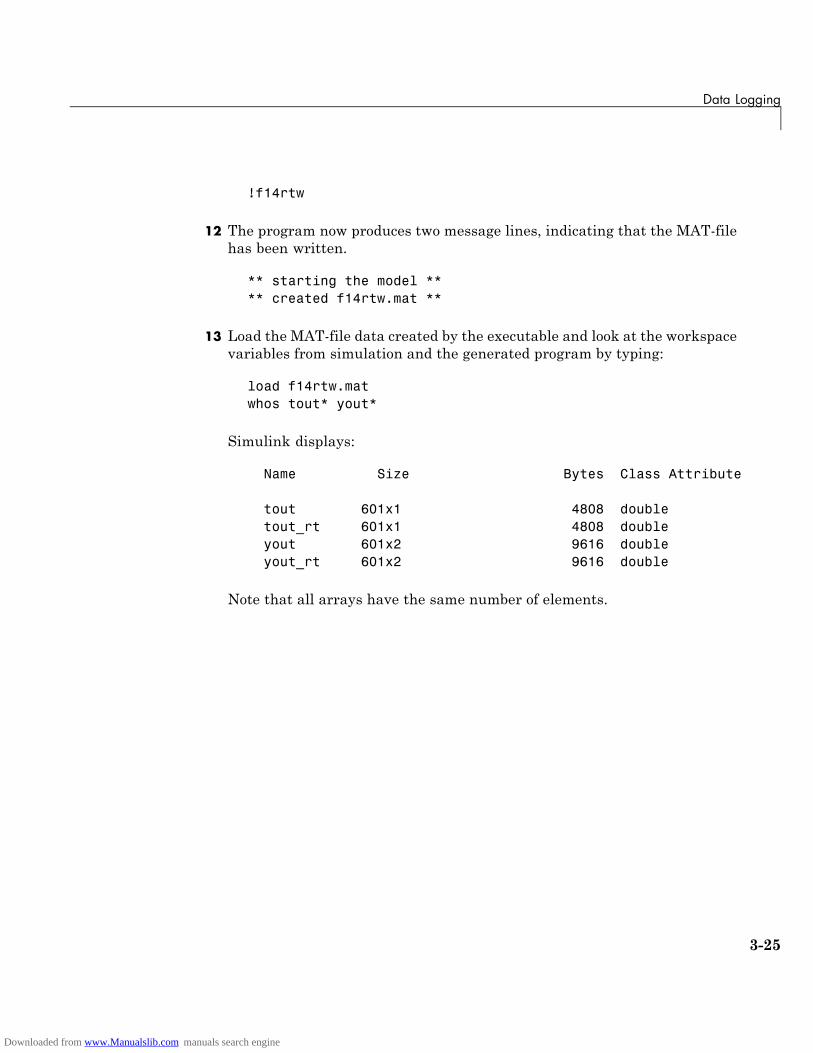
13 Load the MAT-file data created by the executable and look at the workspacevariables from simulation and the generated program by typing:
load f14rtw.matwhos tout* yout*
Simulink displays:
Name Size Bytes Class Attribute
tout 601x1 4808 doubletout_rt 601x1 4808 doubleyout 601x2 9616 doubleyout_rt 601x2 9616 double
Note that all arrays have the same number of elements.
3-25
Downloaded from www.Manualslib.com manuals search engine

3 Working with the Real-Time Workshop® Software
14 Observe that the variables tout_rt (time) and yout_rt (Pilot G Forceand Angle of Attack) have been loaded from the file. Plot Pilot G Forceas a function of time.
plot(tout_rt,yout_rt(:,2))
The resulting plot is identical to the plot you produced in step 10 of theprevious part of this tutorial:
3-26
Downloaded from www.Manualslib.com manuals search engine

Code Verification
Code Verification
In this section...
“Tutorial Overview” on page 3-27
“Logging Signals via Scope Blocks” on page 3-27
“Logging Simulation Data” on page 3-29
“Logging Data from the Generated Program” on page 3-29
“Comparing Numerical Results of the Simulation and the GeneratedProgram” on page 3-31
Tutorial OverviewIn this tutorial, you verify the answers computed by code generated fromthe f14rtw model. You do this by capturing two sets of output data andcomparing the sets. You obtain one set by running the Simulink model, andthe other set by executing the Real-Time Workshop generated code.
Note To obtain a valid comparison between outputs of the model and thegenerated program, you must use the same Solver options and the sameStep size for both the Simulink run and the Real-Time Workshop buildprocess, and the model must be configured to save simulation time, as shownin the preceding tutorial.
Logging Signals via Scope BlocksThis example uses Scope blocks (rather than Outport blocks) to log outputdata. The f14rtw model should be configured as it was at the end of theprevious tutorial, “Data Logging” on page 3-18.
To configure the Scope blocks to log data,
1 Save the model if any unsaved changes exist.
2 Clear the MATLAB workspace to eliminate the results of previoussimulation runs. At the MATLAB prompt, type:
3-27
Downloaded from www.Manualslib.com manuals search engine
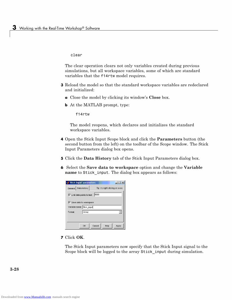
3 Working with the Real-Time Workshop® Software
clear
The clear operation clears not only variables created during previoussimulations, but all workspace variables, some of which are standardvariables that the f14rtw model requires.
3 Reload the model so that the standard workspace variables are redeclaredand initialized:
a Close the model by clicking its window’s Close box.
b At the MATLAB prompt, type:
f14rtw
The model reopens, which declares and initializes the standardworkspace variables.
4 Open the Stick Input Scope block and click the Parameters button (thesecond button from the left) on the toolbar of the Scope window. The StickInput Parameters dialog box opens.
5 Click the Data History tab of the Stick Input Parameters dialog box.
6 Select the Save data to workspace option and change the Variablename to Stick_input. The dialog box appears as follows:
7 Click OK.
The Stick Input parameters now specify that the Stick Input signal to theScope block will be logged to the array Stick_input during simulation.
3-28
Downloaded from www.Manualslib.com manuals search engine
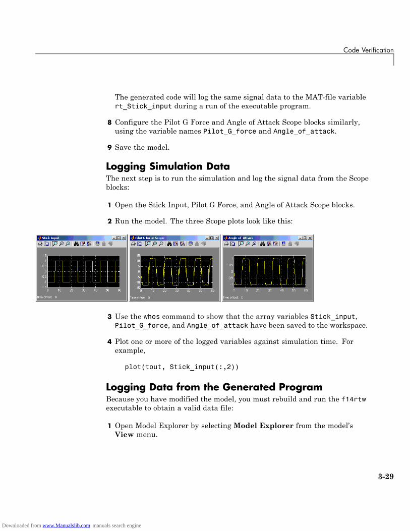
Code Verification
The generated code will log the same signal data to the MAT-file variablert_Stick_input during a run of the executable program.
8 Configure the Pilot G Force and Angle of Attack Scope blocks similarly,using the variable names Pilot_G_force and Angle_of_attack.
9 Save the model.
Logging Simulation DataThe next step is to run the simulation and log the signal data from the Scopeblocks:
1 Open the Stick Input, Pilot G Force, and Angle of Attack Scope blocks.
2 Run the model. The three Scope plots look like this:
3 Use the whos command to show that the array variables Stick_input,Pilot_G_force, and Angle_of_attack have been saved to the workspace.
4 Plot one or more of the logged variables against simulation time. Forexample,
plot(tout, Stick_input(:,2))
Logging Data from the Generated ProgramBecause you have modified the model, you must rebuild and run the f14rtwexecutable to obtain a valid data file:
1 Open Model Explorer by selecting Model Explorer from the model’sView menu.
3-29
Downloaded from www.Manualslib.com manuals search engine
3 Working with the Real-Time Workshop® Software
2 In the Model Hierarchy pane, click the + sign preceding the model nameto reveal its components.
3 Click Configuration (Active) in the left pane.
4 Select Real-Time Workshop on the center pane of theModel Explorer,and click the Interface tab. The Interface pane appears.
5 Set the MAT-file variable name modifier menu to rt_. This prefixesrt_ to each variable that you selected to be logged in the first part of thistutorial.
6 Click Apply.
7 Save the model.
8 Generate code and build an executable by clicking the Build button. Statusmessages in the MATLAB Command Window track the build process.
9 When the build finishes, run the stand-alone program from MATLAB.
!f14rtw
The executing program writes the following messages to the MATLABCommand Window.
** starting the model **** created f14rtw.mat **
10 Load the data file f14rtw.mat and observe the workspace variables.
>> load f14rtw
>> whos rt*
Name Size Bytes Class Attributes
rt_Angle_of_attack 601x2 9616 double
rt_Pilot_G_force 601x2 9616 double
rt_Stick_input 601x2 9616 double
rt_tout 601x1 4808 double
rt_yout 601x2 9616 double
3-30
Downloaded from www.Manualslib.com manuals search engine

Code Verification
11 Use MATLAB to plot three workspace variables created by the executingprogram as a function of time.
figure('Name','Stick_input')plot(rt_tout,rt_Stick_input(:,2))figure('Name','Pilot_G_force')plot(rt_tout,rt_Pilot_G_force(:,2))figure('Name','Angle_of_attack')plot(rt_tout,rt_Angle_of_attack(:,2))
Your Simulink simulations and the generated code have apparentlyproduced nearly identical output. The next section shows how to quantifythis similarity.
Comparing Numerical Results of the Simulation andthe Generated ProgramYou have now obtained data from a Simulink run of the model and from a runof the program generated from the model. It is a simple matter to compare thef14rtw model output to the Real-Time Workshop results. Your comparisonresults may differ from those shown below.
To compare Angle_of_attack (simulation output) to rt_Angle_of_attack(generated program output), type:
max(abs(rt_Angle_of_attack-Angle_of_attack))
MATLAB prints:
ans =1.0e-015 *
0 0.3331
3-31
Downloaded from www.Manualslib.com manuals search engine
3 Working with the Real-Time Workshop® Software
Similarly, the comparison of Pilot_G_force (simulation output) tort_Pilot_G_force (generated program output) is:
max(abs(rt_Pilot_G_force-Pilot_G_force))1.0e-013 *
0 0.4974
Overall agreement is within 10-13. The means of residuals are an order ofmagnitude smaller. This slight error can be caused by many factors, including
• Different compiler optimizations
• Statement ordering
• Runtime libraries
For example, a function call such as sin(2.0) might return a slightlydifferent value depending on which C library you are using. Such variationscan also cause differences between your results and those shown above.
3-32
Downloaded from www.Manualslib.com manuals search engine

First Look at Generated Code
First Look at Generated Code
In this section...
“Tutorial Overview” on page 3-33
“Setting Up the Model” on page 3-33
“Generating Code Without Buffer Optimization” on page 3-35
“Generating Code With Buffer Optimization” on page 3-39
“Further Optimization: Expression Folding” on page 3-41
“HTML Code Generation Reports” on page 3-44
Tutorial OverviewIn this tutorial, you examine code generated from a simple model to observethe effects of some of the many Real-Time Workshop code optimizationfeatures.
Note You can view the code generated from this example using the MATLABeditor. You can also view the code in the MATLAB Help browser if you enablethe Create HTML report option before generating code. See the followingsection, “HTML Code Generation Reports” on page 3-44, for an introductionto using the HTML report feature.
The source model, example.mdl, is shown below.
Setting Up the ModelFirst, create the model from Simulink library blocks, and set up basicSimulink and Real-Time Workshop parameters as follows:
3-33
Downloaded from www.Manualslib.com manuals search engine

3 Working with the Real-Time Workshop® Software
1 Create a directory, example_codegen, and make it your working directory:
!mkdir example_codegencd example_codegen
2 Create a new model and save it as example.mdl.
3 Add Sine Wave, Gain, and Out1 blocks to your model and connect them asshown in the preceding diagram. Label the signals as shown.
4 Open Model Explorer by selecting Model Explorer from the model’sView menu.
5 In the Model Hierarchy pane, click the + sign preceding the model nameto reveal its components.
6 Click Configuration (Active) in the left pane.
7 Select Solver in the center pane. The Solver pane appears at the right.
8 In the Solver Options pane:
a Select Fixed-step in the Type field.
b Select Discrete (no continuous states) in the Solver field.
c Specify 0.1 in the Fixed-step size field. (Otherwise, the Real-TimeWorkshop code generator posts a warning and supplies a default valuewhen you generate code.)
9 Click Apply.
10 Click Data Import/Export in the center pane and make sure all checkboxes in the right pane are cleared. Click Apply if you made any changes.
11 Select Real-Time Workshop in the center pane. Under Target Selectionin the right pane, select the default generic real-time (GRT) target grt.tlc.
12 Select Generate code only at the bottom of the right pane. This optioncauses the Real-Time Workshop software to generate code and a make file,then stop at that point, rather than proceeding to invoke make to compileand link the code. Note that the label on the Build button changes toGenerate code.
3-34
Downloaded from www.Manualslib.com manuals search engine

First Look at Generated Code
13 Click Apply.
14 Save the model.
Generating Code Without Buffer OptimizationWith buffer optimizations Real-Time Workshop software generates code thatreduces memory consumption and execution time. In this tutorial, you disablethe buffer optimizations to see what the nonoptimized generated code lookslike:
1 Select Optimization in the center pane. The Optimization pane appearsat the right. Clear the Signal storage reuse option, as shown below.Change any other attributes as needed to match the figure.
Note Clearing the Signal storage reuse option disables the followingoptions:
• Enable local block outputs
• Reuse block outputs
• Eliminate superfluous local variables (Expression folding)
• Minimize data copies between local and global variables
3-35
Downloaded from www.Manualslib.com manuals search engine
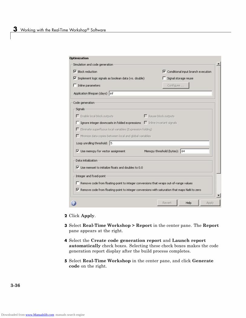
3 Working with the Real-Time Workshop® Software
2 Click Apply.
3 Select Real-Time Workshop > Report in the center pane. The Reportpane appears at the right.
4 Select the Create code generation report and Launch reportautomatically check boxes. Selecting these check boxes makes the codegeneration report display after the build process completes.
5 Select Real-Time Workshop in the center pane, and click Generatecode on the right.
3-36
Downloaded from www.Manualslib.com manuals search engine
First Look at Generated Code
6 Because you selected the Generate code only option, the Real-TimeWorkshop build process does not invoke your make utility. The codegeneration process ends with this message:
### Successful completion of Real-Time Workshopbuild procedure for model: example
7 The generated code is in the build directory, example_grt_rtw. The fileexample_grt_rtw/example.c contains the output computation for themodel. You can view this file in the code generation report by clickingthe example.c link in the left pane.
8 In example.c, find the function example_output near the top of the file.
The generated C code consists of procedures that implement the algorithmsdefined by your Simulink block diagram. The execution engine calls theprocedures in proper succession as time moves forward. The modules thatimplement the execution engine and other capabilities are referred tocollectively as the run-time interface modules. See the Real-Time WorkshopUser’s Guide for a complete discussion of how the Real-Time Workshopsoftware interfaces and executes application, system-dependent, andsystem-independent modules, in each of the two styles of generated code.
In code generated for example, the generated example_output functionimplements the actual algorithm for multiplying a sine wave by a gain.The example_output function computes the model’s block outputs. Therun-time interface must call example_output at every time step. Withbuffer optimizations turned off, example_output assigns unique buffersto each block output. These buffers (rtB.sin_out, rtB.gain_out) aremembers of a global block I/O data structure, called in this code example_Band declared as follows:
/* Block signals (auto storage) */BlockIO_example example_B;
The data type BlockIO_example is defined in example.h as follows:
/* Block signals (auto storage) */extern BlockIO_example example_B;
3-37
Downloaded from www.Manualslib.com manuals search engine
3 Working with the Real-Time Workshop® Software
The output code accesses fields of this global structure, as shown below:
/* Model output function */
static void example_output(int_T tid)
{
/* Sin: '<Root>/Sine Wave' */
example_B.sin_out = sin(example_P.SineWave_Freq * example_M->Timing.t[0] +
example_P.SineWave_Phase) * example_P.SineWave_Amp + example_P.SineWave_Bias;
/* Gain: '<Root>/Gain' */
example_B.gain_out = example_P.Gain_Gain * example_B.sin_out;
/* Outport: '<Root>/Out1' */
example_Y.Out1 = example_B.gain_out;
/* tid is required for a uniform function interface.
* Argument tid is not used in the function. */
UNUSED_PARAMETER(tid);
}
9 In GRT targets such as this, the function example_output is calledby a wrapper function, MdlOutputs. In example.c, find the functionMdlOutputs near the end. It looks like this:
void MdlOutputs(int_T tid){
example_output(tid);}
Note In previous releases, MdlOutputs was the actual output function forcode generated by all GRT-configured models. It is now implemented as awrapper function to provide greater compatibility among different targetconfigurations.
3-38
Downloaded from www.Manualslib.com manuals search engine
First Look at Generated Code
Generating Code With Buffer OptimizationWith buffer optimizations, Real-Time Workshop software generates code thatreduces memory consumption and execution time. In this tutorial, you turnbuffer optimizations on and observe how they improve the code. Enable signalbuffer optimizations and regenerate the code as follows:
1 Change your current working directory to example_codegen if you havenot already done so.
2 Select Optimization in the center pane. The Optimization pane appearsat the right. Select the Signal storage reuse option.
3 Note that the following parameters become enabled in the Codegeneration section:
• Enable local block outputs
• Reuse block outputs
• Eliminate superfluous local variables (Expression folding)
• Minimize data copies between local and global variables
3-39
Downloaded from www.Manualslib.com manuals search engine
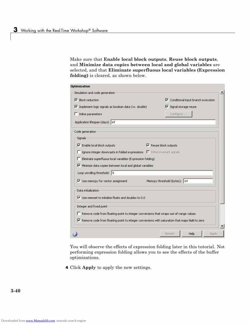
3 Working with the Real-Time Workshop® Software
Make sure that Enable local block outputs, Reuse block outputs,and Minimize data copies between local and global variables areselected, and that Eliminate superfluous local variables (Expressionfolding) is cleared, as shown below.
You will observe the effects of expression folding later in this tutorial. Notperforming expression folding allows you to see the effects of the bufferoptimizations.
4 Click Apply to apply the new settings.
3-40
Downloaded from www.Manualslib.com manuals search engine

First Look at Generated Code
5 Select Real-Time Workshop in the center pane, and click Generatecode on the right.
As before, the Real-Time Workshop software generates code in theexample_grt_rtw directory. The previously generated code is overwritten.
6 View example.c and examine the example_output function.
With buffer optimizations enabled, the code in example_output reuses theexample_Y.Out1 global buffer.
/* Model output function */
static void example_output(int_T tid)
{
/* Sin: '<Root>/Sine Wave' */
example_Y.Out1 = sin(example_P.SineWave_Freq * example_M->Timing.t[0] +
example_P.SineWave_Phase) * example_P.SineWave_Amp +
example_P.SineWave_Bias;
/* Gain: '<Root>/Gain' */
example_Y.Out1 = example_P.Gain_Gain * example_Y.Out1;
/* tid is required for a uniform function interface.
* Argument tid is not used in the function. */
UNUSED_PARAMETER(tid);
}
This code is more efficient in terms of memory usage and execution speed. Byeliminating a global variable and a data copy instruction, the data sectionis smaller and the code is smaller and faster. The efficiency improvementgained by selecting Enable local block outputs, Reuse block outputs,and Minimize data copies between local and global variables is moresignificant in a large model with many signals.
Further Optimization: Expression FoldingAs a final optimization, you turn on expression folding, a code optimizationtechnique that minimizes the computation of intermediate results and theuse of temporary buffers or variables.
Enable expression folding and regenerate the code as follows:
3-41
Downloaded from www.Manualslib.com manuals search engine

3 Working with the Real-Time Workshop® Software
1 Change your current working directory to example_codegen if you havenot already done so.
2 Select Optimization in the center pane. The Optimization pane appears.
3 Select the Eliminate superfluous local variables (Expressionfolding) option.
4 Click Apply.
3-42
Downloaded from www.Manualslib.com manuals search engine

First Look at Generated Code
5 Select Real-Time Workshop in the center pane, and click Generatecode on the right.
The Real-Time Workshop software generates code as before.
6 View example.c and examine the function example_output.
In the previous examples, the Gain block computation was computed in aseparate code statement and the result was stored in a temporary locationbefore the final output computation.
With Eliminate superfluous local variables (Expression folding)selected, there is a subtle but significant difference in the generated code:the gain computation is incorporated (or folded) directly into the Outportcomputation, eliminating the temporary location and separate code statement.This computation is on the last line of the example_output function.
/* Model output function */
static void example_output(int_T tid)
{
/* Outport: '<Root>/Out1' incorporates:
* Gain: '<Root>/Gain'
* Sin: '<Root>/Sine Wave'
*/
example_Y.Out1 = (sin(example_P.SineWave_Freq * example_M->Timing.t[0] +
example_P.SineWave_Phase) * example_P.SineWave_Amp +
example_P.SineWave_Bias) * example_P.Gain_Gain;
/* tid is required for a uniform function interface.
* Argument tid is not used in the function. */
UNUSED_PARAMETER(tid);
}
In many cases, expression folding can incorporate entire model computationsinto a single, highly optimized line of code. Expression folding is turned on bydefault. Using this option will improve the efficiency of generated code.
3-43
Downloaded from www.Manualslib.com manuals search engine

3 Working with the Real-Time Workshop® Software
HTML Code Generation ReportsWhen the Create code generation report check box on the Real-TimeWorkshop > Report pane is selected, a navigable summary of source files isproduced when the model is built. See the figure below.
Selecting this option causes the Real-Time Workshop software to producean HTML file for each generated source file, plus a summary and an indexfile, in a directory named html within the build directory. If the Launchreport automatically option (which is enabled by selecting Create codegeneration report) is also selected, the HTML summary and index areautomatically displayed.
In the HTML report, you can click links in the report to inspect source andinclude files, and view relevant documentation. In these reports,
• Global variable instances are hyperlinked to their definitions.
• Block header comments in source files are hyperlinked back to the model;clicking one of these causes the block that generated that section of codeto be highlighted (this feature requires a Real-Time Workshop EmbeddedCoder license and the ERT target).
3-44
Downloaded from www.Manualslib.com manuals search engine

First Look at Generated Code
An HTML report for the example.mdl GRT target is shown below.
One useful feature of HTML reports is the link on the Summary pageidentifying Configuration Settings at the Time of Code Generation. Clickingthis opens a read-only Configuration Parameters dialog box through whichyou can navigate to identify the settings of every option in place at the timethat the HTML report was generated.
You can refer to HTML reports at any time. To review an existing HTMLreport after you have closed its window, use any HTML browser to open thefile html/model_codgen_rpt.html within your build directory.
3-45
Downloaded from www.Manualslib.com manuals search engine

3 Working with the Real-Time Workshop® Software
Note The contents of HTML reports for different target types vary, andreports for models with subsystems feature additional information. Youcan also view HTML-formatted files and text files for generated code andmodel reference targets withinModel Explorer. See “Generating Code for aReferenced Model” on page 3-60 for more information.
For further information on configuring and optimizing generated code, consultthese sections of the Real-Time Workshop User’s Guide documentation:
• “Building Executables” contains overviews of controlling optimizationsand other code generation options.
• “Optimizing Generated Code” has additional details on signal reuse,expression folding, and other code optimization techniques.
• “Architecture Considerations” has details on the structure and executionof model.c files.
3-46
Downloaded from www.Manualslib.com manuals search engine
Working with External Mode Using GRT
Working with External Mode Using GRT
In this section...
“Tutorial Overview” on page 3-47
“Setting Up the Model” on page 3-48
“Building the Target Executable” on page 3-50
“Running the External Mode Target Program” on page 3-54
“Tuning Parameters” on page 3-58
Tutorial OverviewThis section provides step-by-step instructions for getting started withexternal mode, a very useful environment for rapid prototyping. The tutorialconsists of four parts, each of which depends on completion of the precedingones, in order. The four parts correspond to the steps that you follow insimulating, building, and tuning an actual real-time application:
1 Set up the model.
2 Build the target executable.
3 Run the external mode target program.
4 Tune parameters.
The example presented uses the generic real-time target, and does not requireany hardware other than the computer on which you run the Simulink andReal-Time Workshop software. The generated executable in this exampleruns on the host computer in a separate process from MATLAB and Simulink.
The procedures for building, running, and testing your programs are almostidentical in UNIX and PC environments. The discussion notes differenceswhere applicable.
For a more thorough description of external mode, including a discussion ofall the options available, see “Using the External Mode User Interface” in theReal-Time Workshop documentation.
3-47
Downloaded from www.Manualslib.com manuals search engine

3 Working with the Real-Time Workshop® Software
Setting Up the ModelIn this part of the tutorial, you create a simple model, extmode_example, anda directory called ext_mode_example to store the model and the generatedexecutable:
1 Create the directory from the MATLAB command line by typing
mkdir ext_mode_example
2 Make ext_mode_example your working directory:
cd ext_mode_example
3 Create a model in Simulink with a Sine Wave block for the input signal,two Gain blocks in parallel, and two Scope blocks. The model is shownbelow. Be sure to label the Gain and Scope blocks as shown, so thatsubsequent steps will be clear to you.
4 Define and assign two variables A and B in the MATLAB workspace asfollows:
A = 2; B = 3;
3-48
Downloaded from www.Manualslib.com manuals search engine
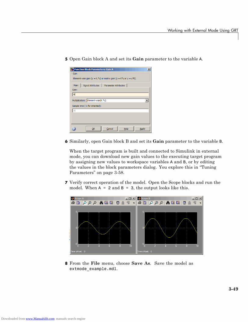
Working with External Mode Using GRT
5 Open Gain block A and set its Gain parameter to the variable A.
6 Similarly, open Gain block B and set its Gain parameter to the variable B.
When the target program is built and connected to Simulink in externalmode, you can download new gain values to the executing target programby assigning new values to workspace variables A and B, or by editingthe values in the block parameters dialog. You explore this in “TuningParameters” on page 3-58.
7 Verify correct operation of the model. Open the Scope blocks and run themodel. When A = 2 and B = 3, the output looks like this.
8 From the File menu, choose Save As. Save the model asextmode_example.mdl.
3-49
Downloaded from www.Manualslib.com manuals search engine
3 Working with the Real-Time Workshop® Software
Building the Target ExecutableIn this section, you set up the model and code generation parameters requiredfor an external mode compatible target program. Then you generate code andbuild the target executable:
1 Open Model Explorer by selecting Model Explorer from the model’sView menu.
2 In the Model Hierarchy pane, click the + sign preceding the model nameto reveal its components.
3 Click Configuration (Active) in the left pane.
4 Select Solver in the center pane. The Solver pane appears at the right.
5 In the Solver Options pane:
a Select Fixed-step in the Type field.
b Select Discrete (no continuous states) in the Solver field.
c Specify 0.1 in the Fixed-step size field. (Otherwise, the Real-TimeWorkshop build process posts a warning and supplies a value when yougenerate code.)
3-50
Downloaded from www.Manualslib.com manuals search engine
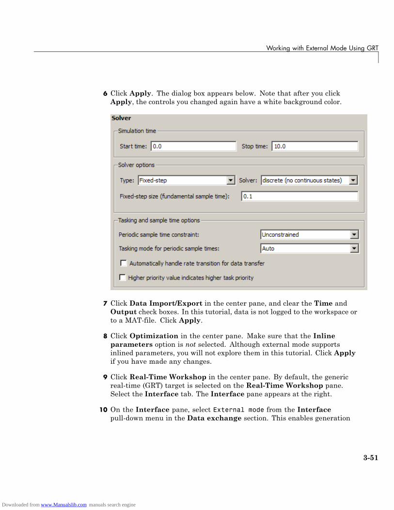
Working with External Mode Using GRT
6 Click Apply. The dialog box appears below. Note that after you clickApply, the controls you changed again have a white background color.
7 Click Data Import/Export in the center pane, and clear the Time andOutput check boxes. In this tutorial, data is not logged to the workspace orto a MAT-file. Click Apply.
8 Click Optimization in the center pane. Make sure that the Inlineparameters option is not selected. Although external mode supportsinlined parameters, you will not explore them in this tutorial. Click Applyif you have made any changes.
9 Click Real-Time Workshop in the center pane. By default, the genericreal-time (GRT) target is selected on the Real-Time Workshop pane.Select the Interface tab. The Interface pane appears at the right.
10 On the Interface pane, select External mode from the Interfacepull-down menu in the Data exchange section. This enables generation
3-51
Downloaded from www.Manualslib.com manuals search engine
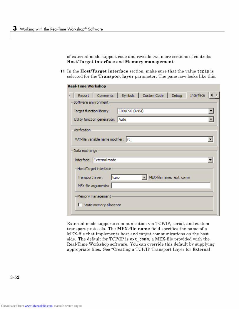
3 Working with the Real-Time Workshop® Software
of external mode support code and reveals two more sections of controls:Host/Target interface and Memory management.
11 In the Host/Target interface section, make sure that the value tcpip isselected for the Transport layer parameter. The pane now looks like this:
External mode supports communication via TCP/IP, serial, and customtransport protocols. The MEX-file name field specifies the name of aMEX-file that implements host and target communications on the hostside. The default for TCP/IP is ext_comm, a MEX-file provided with theReal-Time Workshop software. You can override this default by supplyingappropriate files. See “Creating a TCP/IP Transport Layer for External
3-52
Downloaded from www.Manualslib.com manuals search engine
Working with External Mode Using GRT
Communication” in the Real-Time Workshop documentation for details ifyou need to support other transport layers.
The MEX-file arguments field lets you specify arguments, such as aTCP/IP server port number, to be passed to the external interface program.Note that these arguments are specific to the external interface you areusing. For information on setting these arguments, see “MEX-File OptionalArguments for TCP/IP Transport” and “MEX-File Optional Arguments forSerial Transport” in the Real-Time Workshop documentation.
This tutorial uses the default arguments. Leave theMEX-file argumentsfield blank.
12 Click Apply to save the Interface settings.
13 Save the model.
14 Click Real-Time Workshop in the center pane of the Model Explorer.On the right, make sure that Generate code only is cleared, then clickthe Build button to generate code and create the target program. Thecontent of subsequent messages depends on your compiler and operatingsystem. The final message is
### Successful completion of Real-Time Workshopbuild procedure for model: extmode_example
In the next section, you will run the extmode_example executable and useSimulink as an interactive front end to the running target program.
3-53
Downloaded from www.Manualslib.com manuals search engine
3 Working with the Real-Time Workshop® Software
Running the External Mode Target ProgramThe target executable, extmode_example, is now in your working directory.In this section, you run the target program and establish communicationbetween Simulink and the target.
Note An external-mode program like extmode_example is a host-basedexecutable. Its execution is not tied to RTOS or a periodic timer interrupt, andit does not run in real time. The program just runs as fast as possible, andthe time units it counts off are simulated time units that do not correspond totime in the world outside the program.
The External Signal & Triggering dialog box (accessed via the ExternalMode Control Panel) displays a list of all the blocks in your model thatsupport external mode signal monitoring and logging. The dialog box also letsyou configure the signals that are viewed and how they are acquired anddisplayed. You can use it to reconfigure signals while the target program runs.
In this tutorial, you observe and use the default settings of the ExternalSignal & Triggering dialog box.
3-54
Downloaded from www.Manualslib.com manuals search engine
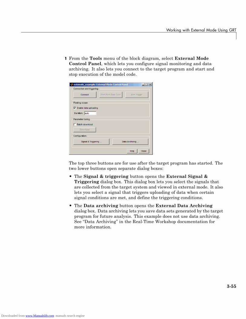
Working with External Mode Using GRT
1 From the Tools menu of the block diagram, select External ModeControl Panel, which lets you configure signal monitoring and dataarchiving. It also lets you connect to the target program and start andstop execution of the model code.
The top three buttons are for use after the target program has started. Thetwo lower buttons open separate dialog boxes:
• The Signal & triggering button opens the External Signal &Triggering dialog box. This dialog box lets you select the signals thatare collected from the target system and viewed in external mode. It alsolets you select a signal that triggers uploading of data when certainsignal conditions are met, and define the triggering conditions.
• The Data archiving button opens the External Data Archivingdialog box. Data archiving lets you save data sets generated by the targetprogram for future analysis. This example does not use data archiving.See “Data Archiving” in the Real-Time Workshop documentation formore information.
3-55
Downloaded from www.Manualslib.com manuals search engine
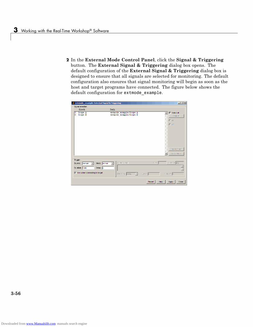
3 Working with the Real-Time Workshop® Software
2 In the External Mode Control Panel, click the Signal & Triggeringbutton. The External Signal & Triggering dialog box opens. Thedefault configuration of the External Signal & Triggering dialog box isdesigned to ensure that all signals are selected for monitoring. The defaultconfiguration also ensures that signal monitoring will begin as soon as thehost and target programs have connected. The figure below shows thedefault configuration for extmode_example.
3-56
Downloaded from www.Manualslib.com manuals search engine

Working with External Mode Using GRT
3 Make sure that the External Signal & Triggering dialog box is set tothe defaults as shown:
• Select all check box is selected. All signals in the Signal selection listare marked with an X in the Block column.
• Trigger Source: manual
• Trigger Mode: normal
• Duration: 1000
• Delay: 0
• Arm when connecting to target: selected
Click Close, and then close the External Mode Control Panel.
For information on the options mentioned above, see “External SignalUploading and Triggering” in the Real-Time Workshop documentation.
4 To run the target program, you must open a command prompt window(on UNIX systems, an Xterm window). At the command prompt, changeto the ext_mode_example directory that you created in step 1. The targetprogram is in this directory.
cd ext_mode_example
Next, type the following command:
extmode_example -tf inf -w
and press Return.
Note On Microsoft Windows platforms, you can also use the “bang”command (!) in the MATLAB Command Window (note that the trailingampersand is required):
!extmode_example -tf inf -w &
The target program begins execution. Note that the target program is in await state, so no activity occurs in the MATLAB Command Window.
3-57
Downloaded from www.Manualslib.com manuals search engine

3 Working with the Real-Time Workshop® Software
The -tf switch overrides the stop time set for the model in Simulink. Theinf value directs the model to run indefinitely. The model code runs untilthe target program receives a stop message from Simulink.
The -w switch instructs the target program to enter a wait state until itreceives a Start real-time code message from the host. This switch isrequired if you want to view data from time step 0 of the target programexecution, or if you want to modify parameters before the target programbegins execution of model code.
5 Open Scope blocks A and B. At this point, no signals are visible on thescopes. When you connect Simulink to the target program and begin modelexecution, the signals generated by the target program will be visible onthe scope displays.
6 The model itself must be in external mode before communication betweenthe model and the target program can begin. To enable external mode,select External from the simulation mode pull-down menu located on theright side of the toolbar of the Simulink window. Alternatively, you canselect External from the Simulation menu.
7 Reopen the External Mode Control Panel (found in the Tools menu)and click Connect. This initiates a handshake between Simulink and thetarget program. When Simulink and the target are connected, the StartReal-Time Code button becomes enabled, and the label of the Connectbutton changes to Disconnect.
8 Click the Start Real-Time Code button. The outputs of Gain blocks A andB are displayed on the two scopes in your model.
Having established communication between Simulink and the running targetprogram, you can tune block parameters in Simulink and observe the effectsthe parameter changes have on the target program. You do this in the nextsection.
Tuning ParametersYou can change the gain factor of either Gain block by assigning a new valueto the variable A or B in the MATLAB workspace. When you change blockparameter values in the workspace during a simulation, you must explicitly
3-58
Downloaded from www.Manualslib.com manuals search engine

Working with External Mode Using GRT
update the block diagram with these changes. When the block diagram isupdated, the new values are downloaded to the target program.
To tune the variables A and B,
1 In the MATLAB Command Window, assign new values to both variables,for example:
A = 0.5;B = 3.5;
2 Activate the extmode_example model window. Select Update Diagramfrom the Edit menu, or press Ctrl+D. As soon as Simulink has updatedthe block parameters, the new gain values are downloaded to the targetprogram, and the effect of the gain change becomes visible on the scopes.
3 You can also enter gain values directly into the Gain blocks. To do this,open the Block Parameters dialog box for Gain block A or B in the model.Enter a new numerical value for the gain and click Apply. As soon asyou click Apply, the new value is downloaded to the target program andthe effect of the gain change becomes visible on the scope. Similarly, youcan change the frequency, amplitude, or phase of the sine wave signalby opening the Block Parameters dialog box for the Sine Wave block andentering a new numerical value in the appropriate field.
Note that because the Sine Wave is a source block, Simulink pauses whilethe Block Parameters dialog box is open. You must close the dialog boxby clicking OK, which allows Simulink to continue and enable you to seethe effect of your changes.
Also note that you cannot change the sample time of the Sine Wave block.Block sample times are part of the structural definition of the model andare part of the generated code. Therefore, if you want to change a blocksample time, you must stop the external mode simulation, reset the block’ssample time, and rebuild the executable.
4 To simultaneously disconnect host/target communication and end executionof the target program, pull down the Simulation menu and select StopReal-Time Code. You can also do this from the External Mode ControlPanel.
3-59
Downloaded from www.Manualslib.com manuals search engine

3 Working with the Real-Time Workshop® Software
Generating Code for a Referenced Model
In this section...
“Tutorial Overview” on page 3-60
“Creating and Configuring a Subsystem Within the vdp Model” on page 3-60
“Converting the Model to Use Model Referencing” on page 3-63
“Generating Model Reference Code for a GRT Target” on page 3-67
“Working with Project Directories” on page 3-70
Tutorial OverviewThe Model block allows an existing Simulink model to be used as a block inanother model. When a model contains one or more Model blocks, it is calleda parent model. Models represented by Model blocks are called referencedmodels in that context.
Model blocks are particularly useful for large-scale modeling applications.They work by generating code and creating a binary file for each referencedmodel, then executing the binary during simulation. The Real-Time Workshopsoftware generates code for referenced models in a slightly different way thanfor top models and stand-alone models, and generates different code thanSimulink does when it simulates them. Follow this tutorial to learn howSimulink and the Real-Time Workshop software handle Model blocks.
In this tutorial, you create a subsystem in an existing model, convert it to areferenced model, call it from the top model via a Model block, and generatecode for both models. You accomplish some of these tasks automatically witha function called Simulink.Subsystem.convertToModelReference. You alsoexplore the generated code and the project directory using the Model Explorer.
Creating and Configuring a Subsystem Within thevdp ModelIn the first part of this tutorial, you define a subsystem for the vdpdemo model, set configuration parameters for the model, and use theSimulink.Subsystem.convertToModelReference function to convert it into
3-60
Downloaded from www.Manualslib.com manuals search engine

Generating Code for a Referenced Model
two new models — the top model (vdptop) and a referenced model vdpmultRMcontaining a subsystem you created (vdpmult):
1 In the MATLAB Command Window, create a new working directorywherever you want to work and cd into it:
mkdir tutorial6cd tutorial6
2 Open the vdp demo model by typing:
vdp
3 Drag a box around the three blocks on the left to select them, as shownbelow:
4 Choose Create Subsystem from the model’s Edit menu.
A subsystem block replaces the selected blocks.
5 If the new subsystem block is not where you want it, move it to a preferredlocation.
6 Rename the block vdpmult.
7 Right-click the vdpmult block and select Subsystem Parameters.
3-61
Downloaded from www.Manualslib.com manuals search engine

3 Working with the Real-Time Workshop® Software
The Function Block Parameters dialog box appears.
8 In the Function Block Parameters dialog box, select Treat as atomicunit, then click OK.
The border of the vdpmult subsystem thickens to indicate that it is nowatomic. An atomic subsystem executes as a unit relative to the parentmodel: subsystem block execution does not interleave with parent blockexecution. This property makes it possible to extract subsystems for use asstand-alone models and as functions in generated code.
The block diagram should now appear as follows:
You must set several properties before you can extract a subsystem for use asa referenced model. To set the necessary properties,
1 Open Model Explorer by selecting Model Explorer from the model’sView menu.
3-62
Downloaded from www.Manualslib.com manuals search engine
Generating Code for a Referenced Model
2 In the Model Hierarchy pane, click the + sign preceding the model nameto reveal its components.
3 Click Configuration (Active) in the left pane.
4 In the center pane, select Solver.
5 In the right pane, under Solver Options change the Type to Fixed-step,then click Apply. You must use fixed-step solvers when generating code,although referenced models can use different solvers than top models.
6 In the center pane, select Optimization. In the right pane, underSimulation and code generation, select Inline parameters. ClickApply.
7 In the center pane, select Diagnostics. In the right pane:
a Select the Data Validity tab. In the Signals area, set Signalresolution to Explicit only.
b Select the Connectivity tab. In the Buses area, setMux blocks usedto create bus signals to error.
8 Click Apply.
The model now has the properties that model referencing requires.
9 In the center pane, click Model Referencing. In the right pane, setRebuild options to If any changes in known dependencies detected.Click Apply. This setting prevents unnecessary code regeneration.
10 In the vdp model window, choose File > Save as. Save the model asvdptop in your working directory. Leave the model open.
Converting the Model to Use Model ReferencingIn this portion of the tutorial, you use the conversion functionSimulink.SubSystem.convertToModelReference to extract the subsystemvdpmult from vdptop and convert vdpmult into a referenced model namedvdpmultRM. To see the complete syntax of the conversion function, type atthe MATLAB prompt:
help Simulink.SubSystem.convertToModelReference
3-63
Downloaded from www.Manualslib.com manuals search engine

3 Working with the Real-Time Workshop® Software
For additional information, type:
doc Simulink.SubSystem.convertToModelReference
If you want to see a demo of Simulink.SubSystem.convertToModelReferencebefore using it yourself, type:
sldemo_mdlref_conversion
Simulink also provides a menu command, Convert to Model Block, thatyou can use to convert a subsystem to a referenced model. The command callsSimulink.SubSystem.convertToModelReference with default arguments.See “Converting a Subsystem to a Referenced Model” in the Simulinkdocumentation.
Extracting the Subsystem to a Referenced ModelTo use Simulink.SubSystem.convertToModelReference to extract vdpmultand convert it to a referenced model, type:
Simulink.SubSystem.convertToModelReference...('vdptop/vdpmult', 'vdpmultRM',...'ReplaceSubsystem', true, 'BuildTarget', 'Sim')
This command:
1 Extracts the subsystem vdpmult from vdptop.
2 Converts the extracted subsystem to a separate model named vdpmultRMand saves the model to the working directory.
3 In vdptop, replaces the extracted subsystem with a Model block thatreferences vdpmultRM.
4 Creates a simulation target for vdptop and vdpmultRM.
The converter prints a number of progress messages, and when successful,terminates with
ans =1
3-64
Downloaded from www.Manualslib.com manuals search engine
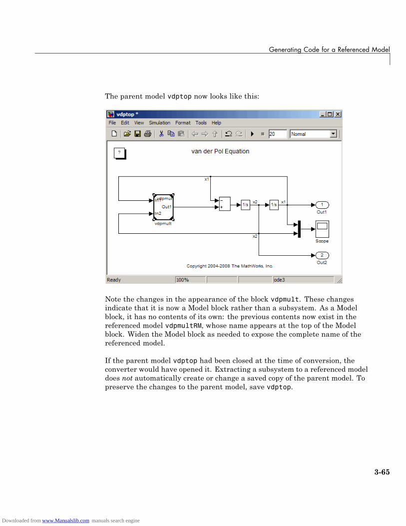
Generating Code for a Referenced Model
The parent model vdptop now looks like this:
Note the changes in the appearance of the block vdpmult. These changesindicate that it is now a Model block rather than a subsystem. As a Modelblock, it has no contents of its own: the previous contents now exist in thereferenced model vdpmultRM, whose name appears at the top of the Modelblock. Widen the Model block as needed to expose the complete name of thereferenced model.
If the parent model vdptop had been closed at the time of conversion, theconverter would have opened it. Extracting a subsystem to a referenced modeldoes not automatically create or change a saved copy of the parent model. Topreserve the changes to the parent model, save vdptop.
3-65
Downloaded from www.Manualslib.com manuals search engine
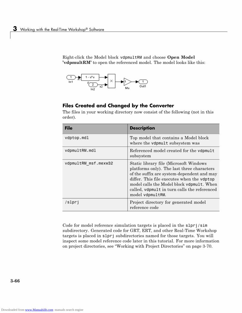
3 Working with the Real-Time Workshop® Software
Right-click the Model block vdpmultRM and choose Open Model’vdpmultRM’ to open the referenced model. The model looks like this:
Files Created and Changed by the ConverterThe files in your working directory now consist of the following (not in thisorder).
File Description
vdptop.mdl Top model that contains a Model blockwhere the vdpmult subsystem was
vdpmultRM.mdl Referenced model created for the vdpmultsubsystem
vdpmultRM_msf.mexw32 Static library file (Microsoft Windowsplatforms only). The last three charactersof the suffix are system-dependent and maydiffer. This file executes when the vdptopmodel calls the Model block vdpmult. Whencalled, vdpmult in turn calls the referencedmodel vdpmultRM.
/slprj Project directory for generated modelreference code
Code for model reference simulation targets is placed in the slprj/simsubdirectory. Generated code for GRT, ERT, and other Real-Time Workshoptargets is placed in slprj subdirectories named for those targets. You willinspect some model reference code later in this tutorial. For more informationon project directories, see “Working with Project Directories” on page 3-70.
3-66
Downloaded from www.Manualslib.com manuals search engine

Generating Code for a Referenced Model
Running the Converted ModelOpen the Scope block in vdptop if it is not visible. In the vdptop window, clickthe Start tool or choose Start from the Simulation menu. The model callsthe vdpmultRM_msf simulation target to simulate. The output looks like this:
Generating Model Reference Code for a GRT TargetThe function Simulink.SubSystem.convertToModelReference created themodel and the simulation target files for the referenced model vdpmultRM. Inthis part of the tutorial, you generate code for that model and the vdptopmodel, and run the executable you create:
1 Verify that you are still working in the tutorial6 directory.
2 If the model vdptop is not open, open it. Make sure it is the active window.
3 Open Model Explorer by selecting Model Explorer from the model’sView menu.
4 In the Model Hierarchy pane, click the + sign preceding the vdptopmodel to reveal its components.
5 Click Configuration (Active) in the left pane.
6 In the center pane, select Data Import/Export.
3-67
Downloaded from www.Manualslib.com manuals search engine

3 Working with the Real-Time Workshop® Software
7 In the Save to workspace section of the right pane, check Time andOutput and clear Data stores. Click Apply. The pane shows the followinginformation:
These settings instruct the model vdptop (and later its executable) to logtime and output data to MAT-files for each time step.
8 Generate GRT code (the default) and an executable for the top model andthe referenced model by selecting Real-Time Workshop in the centerpane and then clicking the Build button.
The Real-Time Workshop build process generates and compiles code. Thecurrent directory now contains a new file and a new directory:
File Description
vdptop.exe The executable created by theReal-Time Workshop build process
vdptop_grt_rtw/ The Real-Time Workshop builddirectory, containing generated codefor the top model
3-68
Downloaded from www.Manualslib.com manuals search engine
Generating Code for a Referenced Model
The Real-Time Workshop build process also generated GRT code for thereferenced model, and placed it in the slprj directory.
To view a model’s generated code in Model Explorer, the model mustbe open. To use the Model Explorer to inspect the newly created builddirectory, vdptop_grt_rtw:
1 Open Model Explorer by selecting Model Explorer from the model’sView menu.
2 In the Model Hierarchy pane, click the + sign preceding the model nameto reveal its components.
3 Click the + sign preceding Code for vdptop to reveal its components.
4 Click This Model that appears directly under Code for vdptop.
A list of generated code files for vdptop appears in the Contents pane:
rtmodel.hvdptop.cvdptop.hvdptop.mkvdptop_private.hvdptop_types.h
3-69
Downloaded from www.Manualslib.com manuals search engine
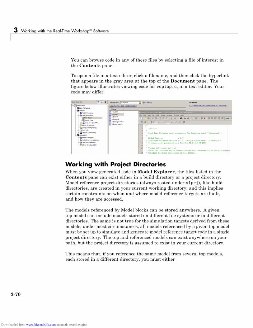
3 Working with the Real-Time Workshop® Software
You can browse code in any of these files by selecting a file of interest inthe Contents pane.
To open a file in a text editor, click a filename, and then click the hyperlinkthat appears in the gray area at the top of the Document pane. Thefigure below illustrates viewing code for vdptop.c, in a text editor. Yourcode may differ.
Working with Project DirectoriesWhen you view generated code in Model Explorer, the files listed in theContents pane can exist either in a build directory or a project directory.Model reference project directories (always rooted under slprj), like builddirectories, are created in your current working directory, and this impliescertain constraints on when and where model reference targets are built,and how they are accessed.
The models referenced by Model blocks can be stored anywhere. A giventop model can include models stored on different file systems or in differentdirectories. The same is not true for the simulation targets derived from thesemodels; under most circumstances, all models referenced by a given top modelmust be set up to simulate and generate model reference target code in a singleproject directory. The top and referenced models can exist anywhere on yourpath, but the project directory is assumed to exist in your current directory.
This means that, if you reference the same model from several top models,each stored in a different directory, you must either
3-70
Downloaded from www.Manualslib.com manuals search engine
Generating Code for a Referenced Model
• Always work in the same directory and be sure that the models are onyour path
• Allow separate project directories, simulation targets, and Real-TimeWorkshop targets to be generated in each directory in which you work
The files in such multiple project directories are generally quite redundant.Therefore, to avoid regenerating code for referenced models more times thannecessary, you might want to choose a specific working directory and remainin it for all sessions.
As model reference code generated for Real-Time Workshop targets as well asfor simulation targets is placed in project directories, the same considerationsas above apply even if you are generating target applications only. That is,code for all models referenced from a given model ends up being generated inthe same project directory, even if it is generated for different targets and atdifferent times.
3-71
Downloaded from www.Manualslib.com manuals search engine
3 Working with the Real-Time Workshop® Software
Documenting a Code Generation Project
In this section...
“Tutorial Overview” on page 3-72
“Generating Code for the Model” on page 3-73
“Opening Report Generator” on page 3-74
“Setting Report Output Options” on page 3-75
“Specifying Models and Subsystems to Include in a Report” on page 3-77
“Setting Component Options” on page 3-77
“Generating the Report” on page 3-78
“Reviewing the Generated Report” on page 3-78
Tutorial OverviewAs explained in “Documenting the Project” on page 2-17, one way ofdocumenting a Real-Time Workshop code generation project is to use theSimulink Report Generator software. In this tutorial, you adjust the SimulinkReport Generator settings to include custom code and then generate a reportfor the Real-Time Workshop demo rtwdemo_f14. A summary of the stepsfor the tutorial follows:
1 Generate code for the model.
2 Open Report Generator.
3 Set report output options.
4 Specify models and subsystems to be included.
5 Set component options.
6 Generate the report.
7 Review the generated report.
3-72
Downloaded from www.Manualslib.com manuals search engine
Documenting a Code Generation Project
Note You need a Simulink Report Generator license to complete steps 3through 5. If you omit those steps and use the default option settings, theresulting output will vary from what is documented in step 6.
For details on using Report Generator, see the Simulink Report GeneratorUser’s Guide.
Generating Code for the ModelBefore you can use Report Generator to document your project, you mustgenerate code for the model. To generate code for the rtwdemo_f14 demo,
1 In the MATLAB Current Folder browser, navigate to a directory whereyou have write access.
2 Create a working directory from the MATLAB command line by typing:
mkdir report_ex
3 Make report_ex your working directory:
cd report_ex
4 Open the rtwdemo_f14 model by clicking the model name below or byentering the model name on the MATLAB command line.
rtwdemo_f14
The model appears in a Simulink model window.
5 In the model window, choose File > Save As, navigate to the workingdirectory, report_ex, and save a copy of the rtwdemo_f14 model asmyf14.mdl.
6 Open Model Explorer by selecting Model Explorer from the model’sView menu.
7 In the Model Hierarchy pane, click the + sign preceding the model nameto reveal its components.
3-73
Downloaded from www.Manualslib.com manuals search engine
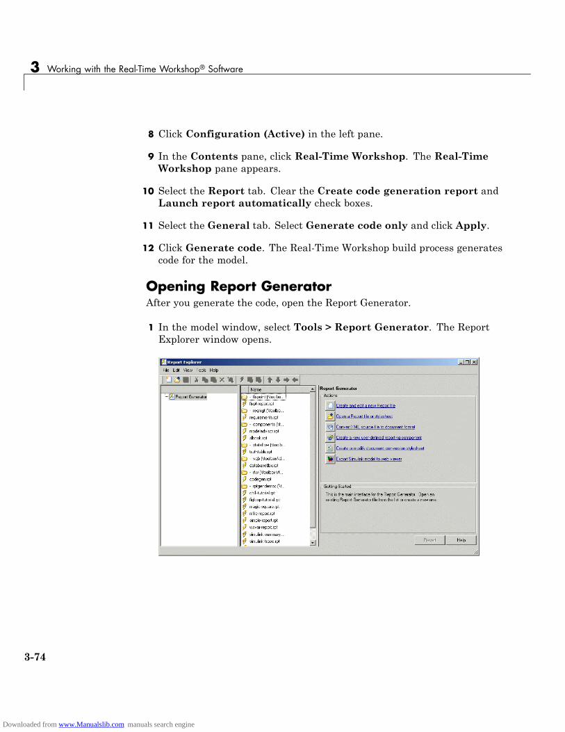
3 Working with the Real-Time Workshop® Software
8 Click Configuration (Active) in the left pane.
9 In the Contents pane, click Real-Time Workshop. The Real-TimeWorkshop pane appears.
10 Select the Report tab. Clear the Create code generation report andLaunch report automatically check boxes.
11 Select the General tab. Select Generate code only and click Apply.
12 Click Generate code. The Real-Time Workshop build process generatescode for the model.
Opening Report GeneratorAfter you generate the code, open the Report Generator.
1 In the model window, select Tools > Report Generator. The ReportExplorer window opens.
3-74
Downloaded from www.Manualslib.com manuals search engine
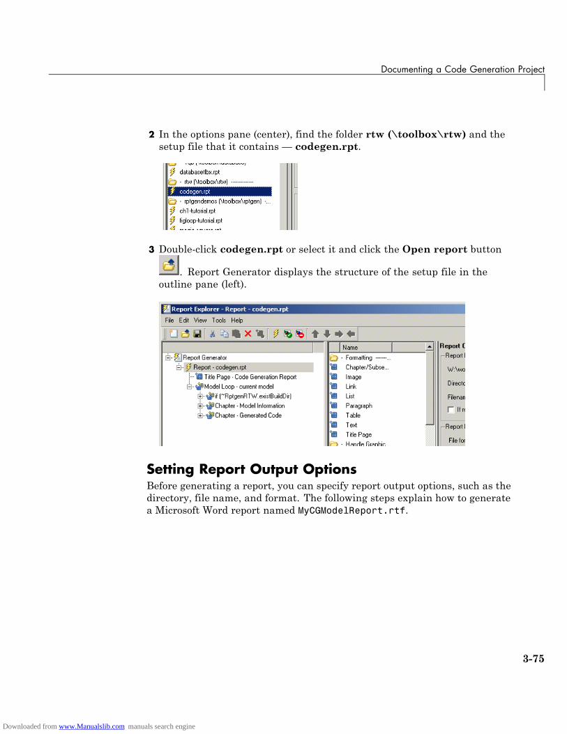
Documenting a Code Generation Project
2 In the options pane (center), find the folder rtw (\toolbox\rtw) and thesetup file that it contains — codegen.rpt.
3 Double-click codegen.rpt or select it and click the Open report button
. Report Generator displays the structure of the setup file in theoutline pane (left).
Setting Report Output OptionsBefore generating a report, you can specify report output options, such as thedirectory, file name, and format. The following steps explain how to generatea Microsoft Word report named MyCGModelReport.rtf.
3-75
Downloaded from www.Manualslib.com manuals search engine
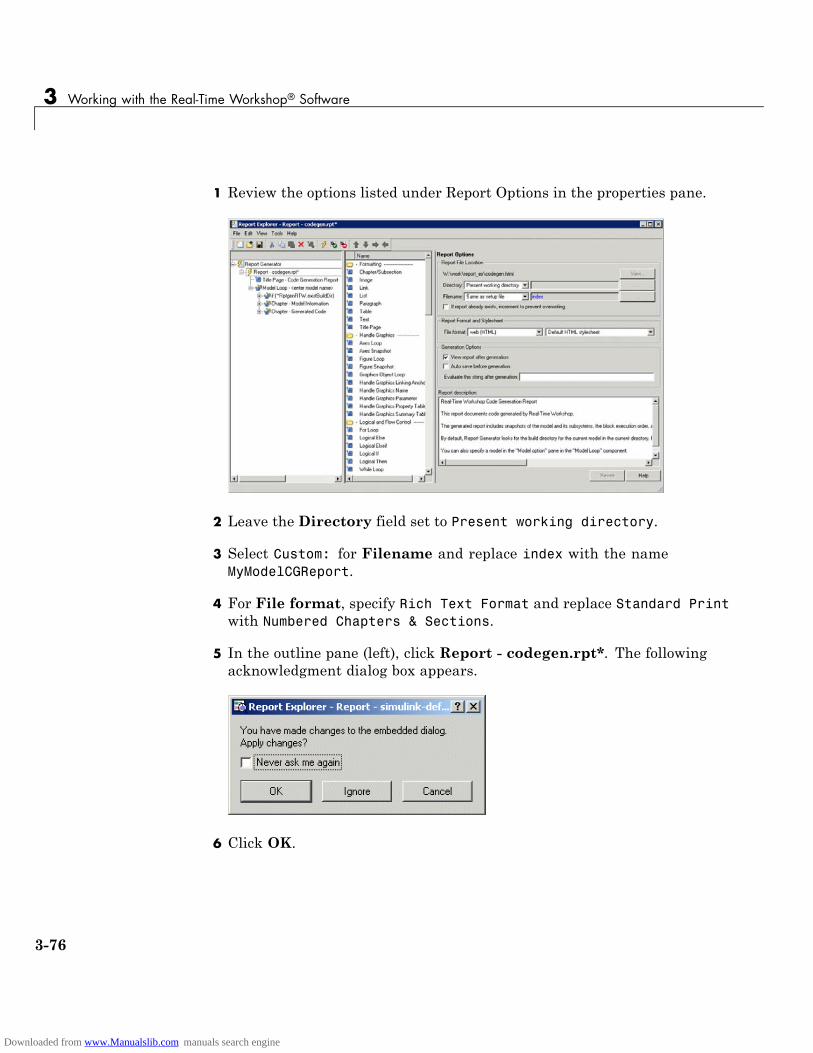
3 Working with the Real-Time Workshop® Software
1 Review the options listed under Report Options in the properties pane.
2 Leave the Directory field set to Present working directory.
3 Select Custom: for Filename and replace index with the nameMyModelCGReport.
4 For File format, specify Rich Text Format and replace Standard Printwith Numbered Chapters & Sections.
5 In the outline pane (left), click Report - codegen.rpt*. The followingacknowledgment dialog box appears.
6 Click OK.
3-76
Downloaded from www.Manualslib.com manuals search engine

Documenting a Code Generation Project
Specifying Models and Subsystems to Include in aReportSpecify the models and subsystems to be included in the generated report bysetting options in the Model Loop component.
1 In the outline pane (left), select Model Loop. Report Generator displaysModel Loop component options in the properties pane.
2 If not already selected, select Current block diagram for the Modelname option.
3 In the outline pane, click Report - codegen.rpt*. If you modified thevalue of the Model name option, the change acknowledgment dialog boxappears. If the dialog box appears, click OK.
Setting Component OptionsAfter setting the report output options, review and, if appropriate, adjustReal-Time Workshop component options.
1 In the outline pane (left), expand the node Chapter - Generated Code.By default, the report includes two sections, each containing one of twoReal-Time Workshop report components.
2 Expand the node Section 1 — Code Generation Summary. The CodeGeneration Summary component appears.
3 Select Code Generation Summary. Options for the component appear inthe properties pane.
4 Click Help to review the report customizations you can make with theCode Generation Summary component. For this tutorial, do not customizethe component.
5 Return focus to the Report Explorer window and expand the node Section1 — Generated Code Listing. The Import Generated Code componentappears.
6 Select Import Generated Code. Options for the component appear inthe properties pane.
3-77
Downloaded from www.Manualslib.com manuals search engine
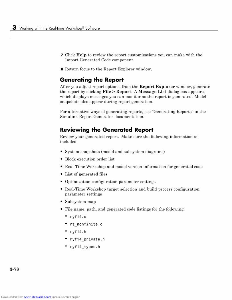
3 Working with the Real-Time Workshop® Software
7 Click Help to review the report customizations you can make with theImport Generated Code component.
8 Return focus to the Report Explorer window.
Generating the ReportAfter you adjust report options, from the Report Explorer window, generatethe report by clicking File > Report. A Message List dialog box appears,which displays messages you can monitor as the report is generated. Modelsnapshots also appear during report generation.
For alternative ways of generating reports, see “Generating Reports” in theSimulink Report Generator documentation.
Reviewing the Generated ReportReview your generated report. Make sure the following information isincluded:
• System snapshots (model and subsystem diagrams)
• Block execution order list
• Real-Time Workshop and model version information for generated code
• List of generated files
• Optimization configuration parameter settings
• Real-Time Workshop target selection and build process configurationparameter settings
• Subsystem map
• File name, path, and generated code listings for the following:
- myf14.c
- rt_nonfinite.c
- myf14.h
- myf14_private.h
- myf14_types.h
3-78
Downloaded from www.Manualslib.com manuals search engine
Documenting a Code Generation Project
- rt_nonfinite.h
- rtmodel.h
- rtwtypes.h
3-79
Downloaded from www.Manualslib.com manuals search engine

3 Working with the Real-Time Workshop® Software
3-80
Downloaded from www.Manualslib.com manuals search engine
Index
IndexAaccelerated simulation
as an application of Real-Time Workshoptechnology 1-14
algorithm developmenttools for 1-6
application requirements 2-4
Bbuild directory
rtwdemo_f14 example 3-15seeing files 3-15
build processmessages in MATLAB Command
Window 3-14
CCode Generation Summary component 3-77code generation tutorial 3-33code verification tutorial 3-27code with buffer optimization 3-41
efficiency 3-41code with expression folding 3-41code without buffer optimization 3-37comments options 3-13configuration parameters 2-6
questions to consider 2-4
Ddata logging 3-18
from generated code 3-29tutorial 3-18via Scope blocks
example 3-27debug options 3-11dialog boxes
Block Parameters 3-49
Configuration Parameters 2-4External Mode Control Panel 3-55External Signal and Triggering 3-56Model Explorer 2-6
directoriesbuild 3-4working 3-4
documentation 3-72
EEmbedded MATLAB Language Subset
for algorithm development 1-6embedded microprocessor
as target environment 1-10executable
running 3-15external mode
building executable 3-50control panel 3-55model setup 3-48parameter tuning 3-58running executable 3-54tutorial 3-47
Ffixed-step solver 3-5
Ggeneric real-time (GRT) target
tutorial 3-4
Hhardware-in-the-loop (HIL) testing
as an application of Real-Time Workshoptechnology 1-14
compared with other types of in-the-looptesting 1-19
Index-1
Downloaded from www.Manualslib.com manuals search engine

Index
host computeras target environment 1-10
host-based simulationcompared to standalone rapid simulations
and prototyping 1-18
IImport Generated Code component 3-77in-the-loop testing
types of 1-19
Mmake utility 2-11MAT-files
creating 3-22loading 3-30
MATLAB Report Generatoropening 3-74setting component options for 3-77setting report output options for 3-75specifying models and subsystems with 3-77
Model Advisor 2-7model encryption
as an application of Real-Time Workshoptechnology 1-14
Model Explorerviewing code in 3-69
model referencingconverting to 3-63definition of 3-60generating code 3-67tutorial 3-60
Oon-target rapid prototyping
as an application of Real-Time Workshoptechnology 1-14
optimizations
expression folding 3-41signal storage reuse 3-39
Pparameters
setting correctly 3-5pilot G Force plot 3-21processor-in-the-loop (PIL) testing
as an application of Real-Time Workshoptechnology 1-14
compared with other types of in-the-looptesting 1-19
production code generationas an application of Real-Time Workshop
technology 1-14project
documenting 3-72project directory
working with 3-70prototyping
types of 1-18
Rrapid prototyping
as an application of Real-Time Workshoptechnology 1-14
compared to simulations and on-targetprototyping 1-18
rapid simulationas an application of Real-Time Workshop
technology 1-14rapid simulations, standalone
compared to host-based simulations andprototyping 1-18
real-time simulatoras target environment 1-10
Real-Time Workshopreport 3-44
Index-2
Downloaded from www.Manualslib.com manuals search engine
Index
Real-Time Workshop Embedded Coder productapplication examples of 1-4key capabilities of 1-4
Real-Time Workshop productapplication examples of 1-4key capabilities of 1-4
Real-Time Workshop Report 3-44Real-Time Workshop technology
applications of 1-14introduction to 1-3prerequisite knowledge for 1-2products associated with 1-3
Report Generatoropening 3-74setting component options for 3-77setting report output options for 3-75specifying models and subsystems with 3-77
report output options 3-75reports
generating code generation 3-72rtwdemo_f14 GRT code generation tutorial 3-4rtwdemo_f14 model 3-3run-time interface modules 3-37
Ssave to workspace options 3-19simulation
types of 1-18Simulink
for algorithm development 1-6Simulink Report Generator
opening 3-74setting component options for 3-77setting report output options for 3-75specifying models and subsystems with 3-77
software-in-the-loop (SIL) testing
as an application of Real-Time Workshoptechnology 1-14
compared with other types of in-the-looptesting 1-19
subsystemsconverting to referenced models 3-63treating as atomic units 3-61
symbols options 3-12system simulation
as an application of Real-Time Workshoptechnology 1-14
Ttarget
how to specify 3-7target environments 1-10target-based (on-target) rapid prototyping
compared to simulations and rapidprototyping 1-18
testingtypes of 1-19
tuning parameters 3-58tutorials
building generic real-time program 3-4code generation 3-33code verification 3-27data logging 3-18external mode 3-47model referencing 3-60
VV-model
applying Real-Time Workshop technologyto 1-16
variable-step solver 3-5
Index-3
Downloaded from www.Manualslib.com manuals search engine