really simple animatronic tail · introduction what kid hasn’t imagined what it’s like having a...
TRANSCRIPT

Really Simple Animatronic TailCreated by Phillip Burgess
Last updated on 2015-05-11 12:50:10 PM EDT

23
45669
121213141516181920202123
2528
3
Guide Contents
Guide ContentsIntroductionWhat kid hasn’t imagined what it’s like having a tail? Let’s make it real!Parts and tools needed:But I don't have a 3D printer!WiringWiring for 3X AAA Battery HolderWiring for USB Power3D Printing and Assembly
PartsHardwareSecure Clip to BotMounting ServoMounting TrinketInstalling TopInstall Clip and Bot into BoxSecure servo horn to tailInstall attachment to servoInstall ZiptieTie the Tail
CodeHow does it work?
© Adafruit Industries https://learn.adafruit.com/really-simple-animatronic-tail Page 2 of 30

IntroductionWhat kid hasn’t imagined what it’s like having a tail? Let’smake it real!
Animatronics is tricky. In addition to the software and electrical engineering of most of our projects,it requires mechanical engineering. Normally when I talk with cosplayers just getting started withelectronics, I point them toward a light (http://adafru.it/f1i) or sound (http://adafru.it/f1j) project, tolimit the number of variables.
This project reduces animatronics to its simplest case. Mechanical tails are complex stuff, ofteninvolving armatures for bones and cable mechanisms (http://adafru.it/f1k) to simulate muscles andtendons. Rather that fighting against gravity, we’ll instead make it our ally. Thinking of the tail as apendulum, a single small servo and a little math is all it takes.
“The cheapest, fastest, and most reliable components are those that aren’t there.”
— Gordon Bell
It’s not the most realistic, but that’s not the goal. We’re learning…the project is modest in scope,with just a few inexpensive components and minimal soldering.
© Adafruit Industries https://learn.adafruit.com/really-simple-animatronic-tail Page 3 of 30
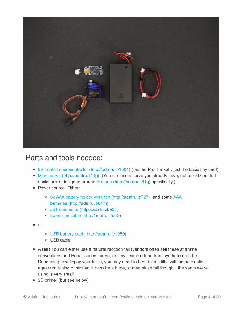
Parts and tools needed:5V Trinket microcontroller (http://adafru.it/1501) (not the Pro Trinket…just the basic tiny one!)Micro servo (http://adafru.it/f1g). (You can use a servo you already have, but our 3D-printedenclosure is designed around this one (http://adafru.it/f1g) specifically.)Power source. Either:
3x AAA battery holder w/switch (http://adafru.it/727) (and some AAAbatteries (http://adafru.it/617))JST connector (http://adafru.it/e2T)Extension cable (http://adafru.it/doS)
or:
USB battery pack (http://adafru.it/1959)USB cable
A tail! You can either use a natural raccoon tail (vendors often sell these at animeconventions and Renaissance faires), or sew a simple tube from synthetic craft fur.Depending how flopsy your tail is, you may need to beef it up a little with some plasticaquarium tubing or similar. It can’t be a huge, stuffed plush tail though…the servo we’reusing is very small.3D printer (but see below).
© Adafruit Industries https://learn.adafruit.com/really-simple-animatronic-tail Page 4 of 30

#4-40 and #2-56 machine screws and nuts for assembling the enclosure.Cable “zip tie” for joining tail to servo clip.
You will also need basic soldering tools and paraphernalia.
But I don't have a 3D printer!Fear not! With some crafting ingenuity, you can work around this…perhaps a cheap cell phoneholster can provide a belt clip. Mint tins make great electronics enclosures (just make sure there’sno electrical contact). Parts such as servos can be held at different angles using materialslike Shapelock plastic (aka Friendly Plastic, Instamorph, etc.).
You could also use a 3D printing service such as Shapeways (http://adafru.it/f1h).
© Adafruit Industries https://learn.adafruit.com/really-simple-animatronic-tail Page 5 of 30

WiringThere are a couple of different ways to power the project: either with a 3x AAA battery holder, orwith a USB battery pack. Which power source you choose determines how things should beconnected…
Wiring for 3X AAA Battery HolderAdvantages of using a 3x AAA battery holder are that it's inexpensive and the connection is robust;it’s not likely to fall out. You can also get replacement batteries just about anywhere. And the powerwire is more discreet.
Alkaline batteries are recommended for this configuration; rechargeable NiMH cells have a lowervoltage and won’t drive the servo with sufficient force. This is also why we’re not using a 3.7VLiPoly battery.
You’ll need to add a JST connector to the Trinket, and a JST extension cable. The battery pack canthen be carried in a pocket.
Start by “tinning” one of the JST pads on the backof the Trinket…heat the pad and apply solder sothe whole surface is covered.
Hold the JST socket in place (tweezersrecommended) and re-melt the solder, allowing thepart to sink into position.
Once this first pin is tacked down, the rest areeasy. Remember to heat the parts, then applysolder…do not melt solder on the iron and “wipe” iton the parts…that makes a weak cold solderjoint. Properly done, the connections should beshiny and smooth.
Congrats, you’ve done surface-mount soldering!
© Adafruit Industries https://learn.adafruit.com/really-simple-animatronic-tail Page 6 of 30

Clip off the connector from the servo, leaving about3 inches of cable attached, then strip and tin theends of the wires. Then solder the following
© Adafruit Industries https://learn.adafruit.com/really-simple-animatronic-tail Page 7 of 30
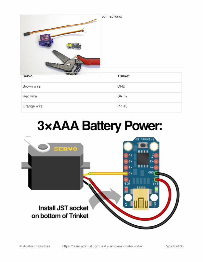
connections:
Servo Trinket
Brown wire GND
Red wire BAT +
Orange wire Pin #0
© Adafruit Industries https://learn.adafruit.com/really-simple-animatronic-tail Page 8 of 30

Wiring for USB PowerI'm not especially fond of USB batteries for wearable projects — USB plugs lack a latchingconnector and pull out too easily — but the fact remains that a lot of people already have thesebattery packs around for charging a cell phone, and may want to put it to other uses.
You don’t need the JST socket or extension when using USB power, just a suitable USB cable. Thebattery can be carried in a pocket.
Clip off the connector from the servo, leaving about3 inches of cable attached, then strip and tin theends of the wires. Then solder the followingconnections:
Servo Trinket
Brown wire GND
Red wire USB +
Orange wire Pin #0
© Adafruit Industries https://learn.adafruit.com/really-simple-animatronic-tail Page 9 of 30

�
Just three connections! Simple and adorable.
Why the different connections for USB vs AAA?Servos sometimes need a lot of current. Best way to ensure this is to wire directly to the powersource. The Trinket’s '5V' pin is only rated for 150 milliamps, but the servo may want as muchas 350 mA at times. The 'USB+' pin goes directly to USB, and 'BAT+' directly to the battery pack.
© Adafruit Industries https://learn.adafruit.com/really-simple-animatronic-tail Page 10 of 30

�
�
In reality, we probably could get away with using the 5V pin…the servo only operatesintermittently…but that would set a bad example. You might decide to adapt this project intonew things that make more vigorous use of servos…wired wrong, either the servoresponse would be anemic or one would risk burning out the voltage regulator. So instead,there’s different wiring for different power sources.
Can I use a 3V Trinket instead?Sure! In the Arduino IDE, select “Trinket 16 MHz” from the Tools®Board menu regardless.
I’m using a different servo with different-colored wires. Will it work?Most likely, yes. The +V wire is always red. Ground is usually black or sometimes brown. Signalmay be orange, yellow, white or blue.
© Adafruit Industries https://learn.adafruit.com/really-simple-animatronic-tail Page 11 of 30

3D Printing and AssemblyParts
This enclosure is four pieces that are fasten together with machine screws. These parts areoptimized to print on FDM based machines with no support material.
Download Files
http://adafru.it/f8W
© Adafruit Industries https://learn.adafruit.com/really-simple-animatronic-tail Page 12 of 30

Hardware
The holes in the parts are sized for #4-40 3/8 flat phillips machine screws. You'll need six screwsfor this project and a screw driver.
File Settings Print Time
servoTail-bot.stl
220c2 shells15% infill0.2 layer height40 speed
about 15 minutes
servoTail-box.stl - about 35 minutes
servoTail-clip.stl - about 25 minutes
servoTail-top.stl - about 10 minutes
servoTail-attachment.stl - about 5 minutes
© Adafruit Industries https://learn.adafruit.com/really-simple-animatronic-tail Page 13 of 30
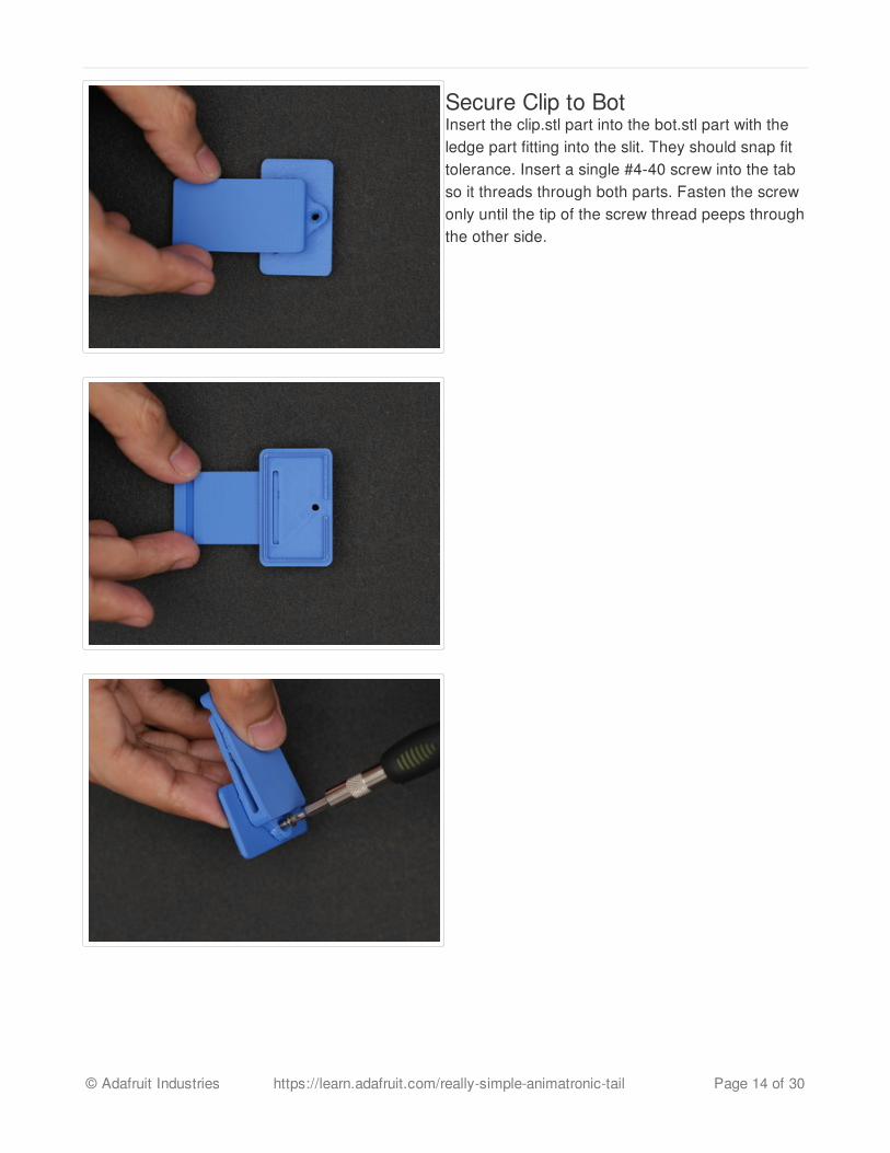
Secure Clip to BotInsert the clip.stl part into the bot.stl part with theledge part fitting into the slit. They should snap fittolerance. Insert a single #4-40 screw into the tabso it threads through both parts. Fasten the screwonly until the tip of the screw thread peeps throughthe other side.
© Adafruit Industries https://learn.adafruit.com/really-simple-animatronic-tail Page 14 of 30
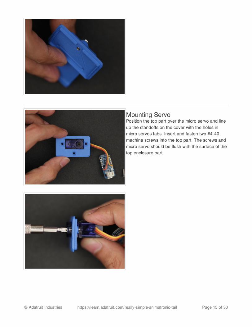
Mounting ServoPosition the top part over the micro servo and lineup the standoffs on the cover with the holes inmicro servos tabs. Insert and fasten two #4-40machine screws into the top part. The screws andmicro servo should be flush with the surface of thetop enclosure part.
© Adafruit Industries https://learn.adafruit.com/really-simple-animatronic-tail Page 15 of 30
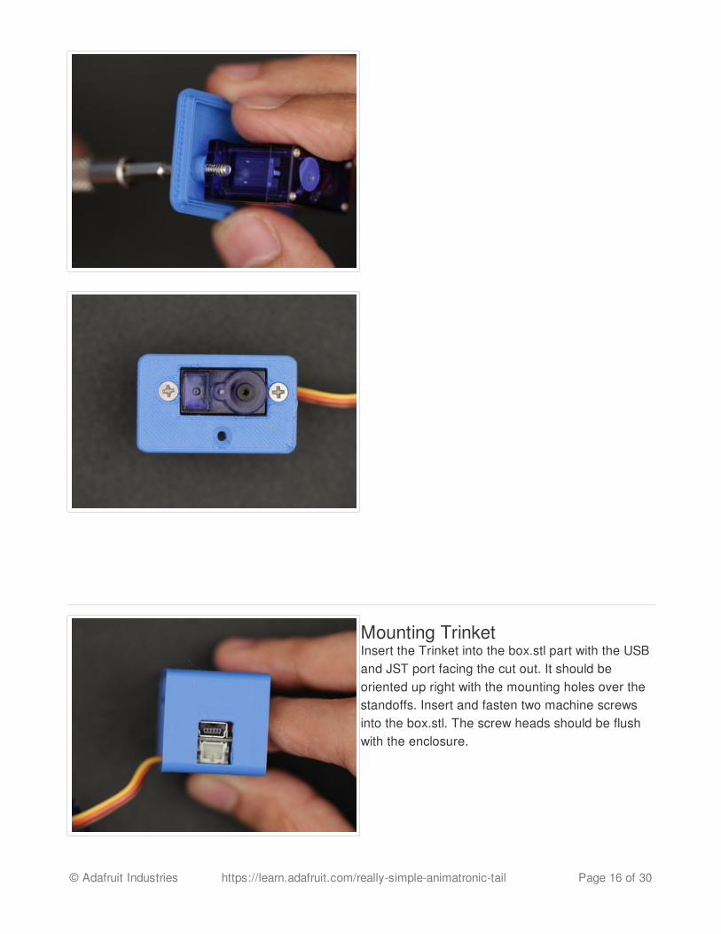
Mounting TrinketInsert the Trinket into the box.stl part with the USBand JST port facing the cut out. It should beoriented up right with the mounting holes over thestandoffs. Insert and fasten two machine screwsinto the box.stl. The screw heads should be flushwith the enclosure.
© Adafruit Industries https://learn.adafruit.com/really-simple-animatronic-tail Page 16 of 30
© Adafruit Industries https://learn.adafruit.com/really-simple-animatronic-tail Page 17 of 30

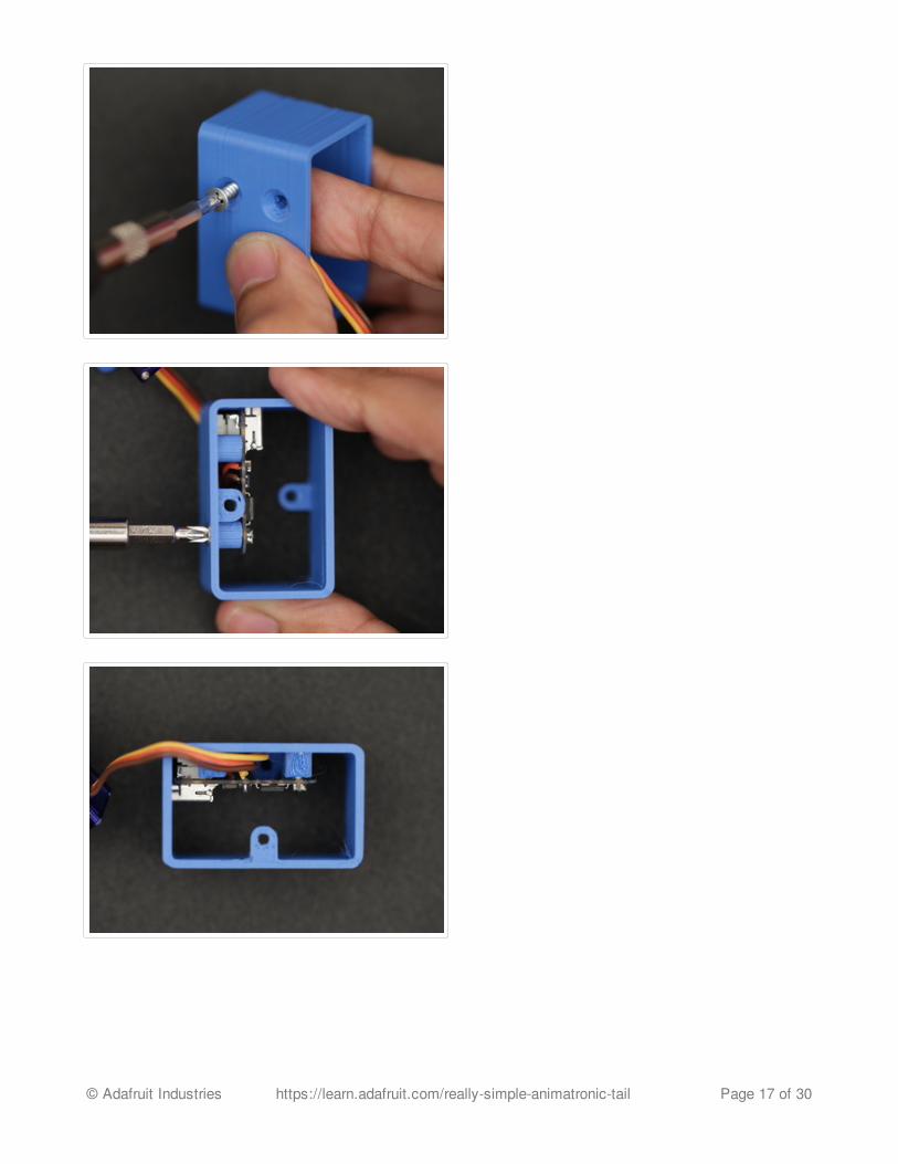
Installing TopPosition the top.stl part over the box.stl part wherethe lip inserts to the frame. Press it down intoplace. Insert and fasten a #4-40 machine screwinto the mounting hole near the bottom center ofthe top.stl part.
© Adafruit Industries https://learn.adafruit.com/really-simple-animatronic-tail Page 18 of 30
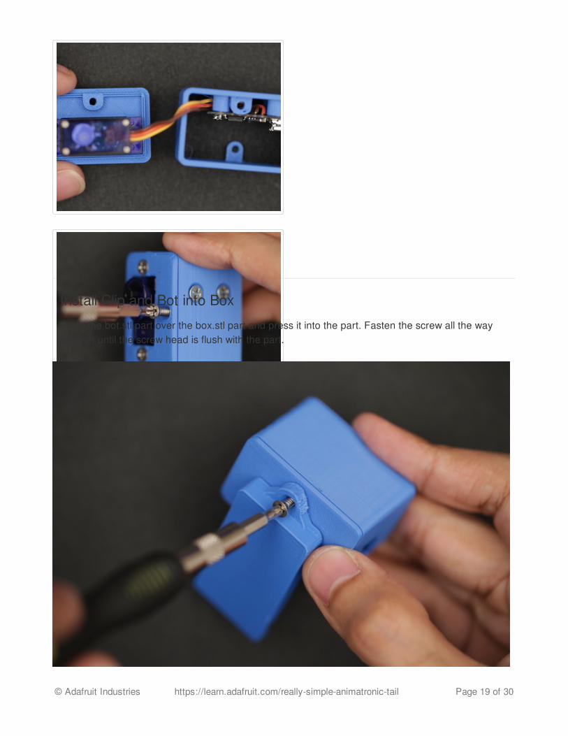
Install Clip and Bot into Box
Place the bot.stl part over the box.stl part and press it into the part. Fasten the screw all the waythrough until the screw head is flush with the part.
© Adafruit Industries https://learn.adafruit.com/really-simple-animatronic-tail Page 19 of 30
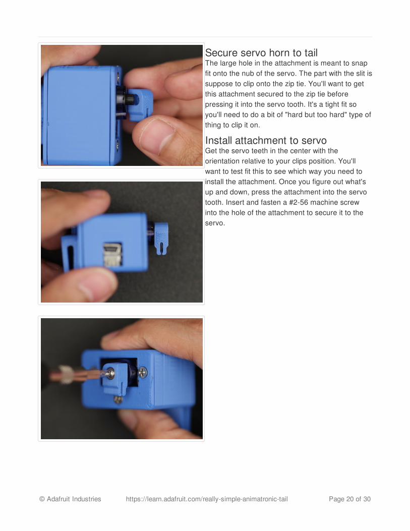
Secure servo horn to tailThe large hole in the attachment is meant to snapfit onto the nub of the servo. The part with the slit issuppose to clip onto the zip tie. You'll want to getthis attachment secured to the zip tie beforepressing it into the servo tooth. It's a tight fit soyou'll need to do a bit of "hard but too hard" type ofthing to clip it on.
Install attachment to servoGet the servo teeth in the center with theorientation relative to your clips position. You'llwant to test fit this to see which way you need toinstall the attachment. Once you figure out what'sup and down, press the attachment into the servotooth. Insert and fasten a #2-56 machine screwinto the hole of the attachment to secure it to theservo.
© Adafruit Industries https://learn.adafruit.com/really-simple-animatronic-tail Page 20 of 30

Install ZiptieThe slit in the servo horn is sized for a ziptie that's4.5mm wide by thick 1.4mm. Find the center of theziptie and gently fit it inside the slit of the servohorn. The ziptie is held in place with friction - applyadhesives for a perminent hold.
© Adafruit Industries https://learn.adafruit.com/really-simple-animatronic-tail Page 21 of 30

Tie the Tail
The tail we used in this project has an hoop near the top. It came with a small bead chain that wasthreaded through the hoop. It's a great pace to thread the ziptie. String it through and tie it howevertight you'd like.
© Adafruit Industries https://learn.adafruit.com/really-simple-animatronic-tail Page 22 of 30
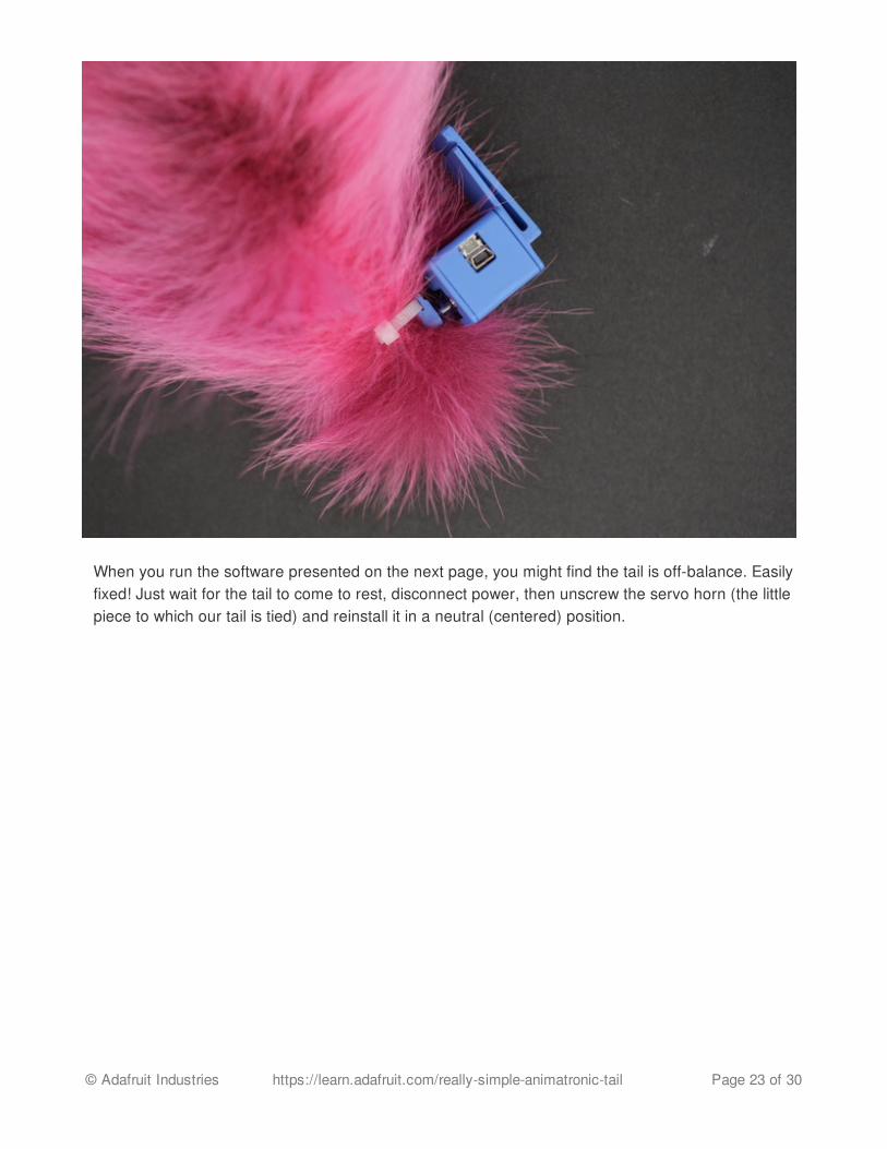
When you run the software presented on the next page, you might find the tail is off-balance. Easilyfixed! Just wait for the tail to come to rest, disconnect power, then unscrew the servo horn (the littlepiece to which our tail is tied) and reinstall it in a neutral (centered) position.
© Adafruit Industries https://learn.adafruit.com/really-simple-animatronic-tail Page 23 of 30

CodeYou’ll need to have the Arduino IDE software configured for use with the Adafruit Trinket. If you’venot done that before, it’s explained in this guide (http://adafru.it/eUF).
Copy the code below and paste it into a new Arduino sketch.
(Instructions continue below, after the code.)
/*Simple servo tail wagger for Adafruit 5V Trinket (not Pro) microcontroller.Uses servo on pin 0. The tail has no 'tendons' -- it's a passive thing,simply hanging off the servo -- though a weak 'spine' (such as aquarium tube)adds just enough body to help. Pendulum math is then used to induce areasonable wag effect.
To break up the repetition and appear a little more 'alive,' the speed,magnitude and duration of the tail wag is randomized (within certain ranges),and it periodically settles down and stops (adds variety and also saves somebattery). There's an optimal period (single-swing time) for a given taillength, but it may randomly go a little faster or slower than this to addsome 'english' to the wag.
You'll need to calibrate this, editing a few lines below. TAIL_LENGTH is thelength of the tail in meters (e.g. a 40 cm tail is 0.4 meters); for inches,multiply by 2.54 to get centimeters, then divide by 100 for meters.SERVO_MIN and SERVO_MAX are the pulse times (in microseconds) for the leftmostand rightmost servo positions; though nominally these are 1000 and 2000 usec(1.0 to 2.0 milliseconds), every servo in reality is a little different, andyou'll need to tune these values for your actual desired swing range.*/
#ifdef __AVR_ATtiny85__ #include <avr/power.h>#endif
// CONFIGURABLE STUFF --------------------------------------------------------
#define TAIL_LENGTH 0.4 // Nominal tail length (meters)#define SERVO_PIN 0 // Servo is connected here#define SERVO_MIN 500 // Servo pulse times#define SERVO_MAX 1800 // in microseconds
// Tail cycles through four states: off, ramp up, steady wag, ramp down.// Durations are semi-random; this table sets min & max times for each.static const uint8_t PROGMEM modeTime[4][2] = {
© Adafruit Industries https://learn.adafruit.com/really-simple-animatronic-tail Page 24 of 30

static const uint8_t PROGMEM modeTime[4][2] = { { 4, 9 }, // 4 to 9 second off time { 3, 6 }, // 3 to 6 second ramp up { 4, 12 }, // 4 to 12 sec steady wag { 2, 5 } // 2 to 5 sec ramp down};
// SHOULDN'T NEED TO EDIT BELOW THIS LINE ------------------------------------
#define SERVO_RANGE (SERVO_MAX - SERVO_MIN)#define MODE_OFF 0#define MODE_RAMP_UP 1#define MODE_HOLD 2#define MODE_RAMP_DOWN 3
uint8_t tailMode = MODE_OFF;float wagnitude = 0.8, // Magnitude of current wag cycle period = M_PI * 2.0 * sqrt(TAIL_LENGTH / 9.8);uint32_t modeStartTime = 0, modeDuration = 0, lastPulseTime = 0;
// SETUP just configures prescaler & enables servo output --------------------
void setup() {#if defined(__AVR_ATtiny85__) && (F_CPU == 16000000L) clock_prescale_set(clock_div_1); // 16 MHz Trinket (not Pro) requires this#endif pinMode(SERVO_PIN, OUTPUT); randomSeed(analogRead(1));}
// LOOP does all the tail-waggling math --------------------------------------
void loop() { uint32_t t = millis(); // Elapsed time, milliseconds
// Compare time in current mode against planned duration if((t - modeStartTime) > modeDuration) { // Time's up! for(;;) { if(++tailMode > MODE_RAMP_DOWN) // Cycle to next mode, tailMode = MODE_OFF; // wrap if needed modeDuration = 1000 * random( // Randomize mode duration pgm_read_byte(&modeTime[tailMode][0]), pgm_read_byte(&modeTime[tailMode][1])); if(tailMode != MODE_OFF) break; // If 'off' mode... // Randomize magnitude of next wag cycle (70% to 100%)
© Adafruit Industries https://learn.adafruit.com/really-simple-animatronic-tail Page 25 of 30
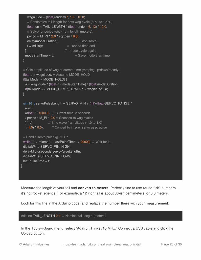
Measure the length of your tail and convert to meters. Perfectly fine to use round “ish” numbers…it’s not rocket science. For example, a 12 inch tail is about 30-ish centimeters, or 0.3 meters.
Look for this line in the Arduino code, and replace the number there with your measurement:
In the Tools®Board menu, select “Adafruit Trinket 16 MHz.” Connect a USB cable and click theUpload button.
// Randomize magnitude of next wag cycle (70% to 100%) wagnitude = (float)random(7, 10) / 10.0; // Randomize tail length for next wag cycle (60% to 120%) float len = TAIL_LENGTH * (float)random(6, 12) / 10.0; // Solve for period (sec) from length (meters): period = M_PI * 2.0 * sqrt(len / 9.8); delay(modeDuration); // Stop servo, t = millis(); // revise time and } // mode-cycle again modeStartTime = t; // Save mode start time }
// Calc amplitude of wag at current time (ramping up/down/steady) float a = wagnitude; // Assume MODE_HOLD if(tailMode != MODE_HOLD) { a = wagnitude * (float)(t - modeStartTime) / (float)modeDuration; if(tailMode == MODE_RAMP_DOWN) a = wagnitude - a; }
uint16_t servoPulseLength = SERVO_MIN + (int)((float)SERVO_RANGE * ((sin( ((float)t / 1000.0) // Current time in seconds / period * M_PI * 2.0 // Seconds to wag cycles ) * a) // Sine wave * amplitude (-1.0 to 1.0) + 1.0) * 0.5); // Convert to integer servo usec pulse
// Handle servo pulse @ 50 Hz... while(((t = micros()) - lastPulseTime) < 20000); // Wait for it... digitalWrite(SERVO_PIN, HIGH); delayMicroseconds(servoPulseLength); digitalWrite(SERVO_PIN, LOW); lastPulseTime = t;}
#define TAIL_LENGTH 0.4 // Nominal tail length (meters)
© Adafruit Industries https://learn.adafruit.com/really-simple-animatronic-tail Page 26 of 30

Normally the reset button is used to start the Trinket bootloader and upload code…but inside theenclosure, this can’t be reached. Plugging in the USB cable has the same effect…there’s about a10 second window to start uploading code to the board.
After uploading…if using the 3xAAA battery pack, unplug the USB cable and switch the batterypack on. The servo will not run off USB in this configuration. This is normal.
If all goes well, the tail will be quiet for a moment, then gradually start to wag. After a few secondsit’ll settle down, then start up again, perhaps with a slightly different speed.
If the swinging is off-center, there’s a fix. Look for these two lines in the code:
Servos expect a continuous series of pulses (about 50 times per second…50 Hz). The “on” time ofeach pulse indicates the servo position. Nominally this time is said to be between 1 and 2milliseconds (1,000 and 2,000 microseconds) to represent the full range of motion…but everyservo’s a little different, and the range of values could go higher or lower. So you may need toexperiment with different values and upload the revised code to the board.
If the amount of rotation is acceptable, and it’s not running up against the left or right limits of theservo…just off-center…an easier option is just to unscrew the servo horn (the bit to which thetail is tied) and re-attach it at the desired angle.
How does it work?The code is based on a formula devised by Galileo Galilei (http://adafru.it/f1l) in the early 1600s…that the period (swing time) of a pendulum is much more dependent on its length than theamplitude of its swing…in fact, for small swing ranges the amplitude can be ignored.
#define SERVO_MIN 500 // Servo pulse times#define SERVO_MAX 1800 // in microseconds
© Adafruit Industries https://learn.adafruit.com/really-simple-animatronic-tail Page 27 of 30

L is the length of the pendulum (our tail), in meters. g is acceleration due to gravity — about 9.8meters/second² on Earth. T is the resulting approximate period in seconds. Then we just use a sinewave matching that period.
The code cycles through four states: resting (no wagging), ramp up, steady wag, and ramp down.During all but the resting phase, the period of the swing remains the same (using the aboveformula)…only the amplitude changes. Gradually ramping up imparts just a little bit of extra energyon each cycle…a bit like kicking your legs on a swing. This is how we’re able to use such a smalland inexpensive servo.
The four states are slightly randomized…it may rest or wag a little more or less on some cycles,
© Adafruit Industries https://learn.adafruit.com/really-simple-animatronic-tail Page 28 of 30

and may go a bit faster or swing higher at times. A little unpredictability like this helps make it a littlemore believable or “alive” — our brains pick up very quickly on obvious repeating patterns!
© Adafruit Industries https://learn.adafruit.com/really-simple-animatronic-tail Page 29 of 30