real-time vision-based tracking control...
TRANSCRIPT

Pergamon
0957-4158 (95) 00060-7
Mechatronics Vol. 5, No. 8, pp. 973-991, 1995 ~) 1995 Elsevier Science Ltd
Printed in Great Britain. All rights reserved. 0957-4158/95 $9.50+0.00
REAL-TIME VISION-BASED TRACKING CONTROL OF AN UNMANNED VEHICLE
KOK-MENG LEE, ZHI ZHOU, ROBERT BLENIS and ERIK BLASCH
The George W. Woodruff School of Mechanical Engineering, Georgia Institute of Technology, Atlanta, GA 30332-0405, U.S.A.
(Received 10 January 1995; revised and accepted 10 July 1995)
Abstract--Recent advances in manufacturing automation have motivated vision-based control of autonomous vehicles operated in unattended factories, material handling processes, warehouse operations, and hazardous environment explorations. Existing vision-based tracking control systems of autonomous vehicles, however, have been limited in real-time applications due to slow and/or expensive visual feedback and complicated dynamics and control with nonholonomic constraints. This paper presents a practical real-time vision-based tracking control system of an unmanned vehicle, ViTra. Unlike the conventional RS170 video-based machine vision systems, ViTra uses a DSP-based flexible integrated vision system (FIVS) which is characterized by low cost, computational efficiency, control flexibility, and a friendly user interface.
In particular, this paper focuses on developing a framework for vision tracking systems, designing generic fiducial patterns, and applying real-time vision systems to tracking control of autonomous vehicles. A laboratory prototype vision-based tracking system developed at Georgia Institute of Technology permits the uniquely designed fiducial landmarks to be evaluated experimentally, the control strategy and the path planning algorithm derived in the paper to be validated in real-time, and the issues of simplifying nonlinear dynamics and dealing with nonholonomic constraints to be addressed in practice. Experimental results reveal interesting insights into the design, manufacture, modeling, and control of vision-based tracking control systems of autonomous vehicles.
1. INTRODUCTION
Advances in manufacturing automation have increased the demand for autonomous vehicles which can be operated in unattended factories, material handling processes, warehouse operations, and hazardous environment explorations. Automatic control of an unmanned vehicle requires real-time position and/or velocity feedback. One way to provide the feedback information is to use machine vision. However, commonly used RS170 video-based machine vision systems for the feedback have generally been computationally expensive and/or slow [1]. This paper investigates a practical machine vision system for locating and tracking, in real-time, a moving vehicle, and addresses the control issues of simplifying nonlinear dynamics and dealing with nonholonomic constraints of an unmanned vehicle.
Autonomous vehicles can be used in a structured and/or unstructured environment. Although extensive research on autonomous vehicle navigation and localization has been conducted in an unstructured environment, these efforts have largely been directed towards applications for exploratory tasks [2, 3]. In many material handling and automated manufacturing processes, such as warehouse operation and automated vehicle control, however, time schedule, flexibility, and high repeatability are of
973

974 KOK-MENG LEE et al.
primary concerns. Creative use of structured optics can effectively enhance vehicle operation in an unstructured environment. Wargocki and Ray used a retroreflective field tracker as a position-measuring instrument in a space solar array application [4]. Recently, Lee and Qian demonstrated the application of a flexible integrated vision system for pursuing a moving target [5]. Clearly, potential applications of reliable and cost-effective autonomous vehicles operated in a structured environment are abundant although many technical issues remain to be addressed and the cost of implementa- tion has often been underestimated.
The major difficulties encountered in vision-based tracking control are two-fold: slow and/or expensive visual feedback and complicated dynamics and control with nonholonomic constraints in "target-space" where the vehicle is located and oriented. Many attempts have been made in recent years to address the problem from the vision and/or the control perspectives. Due to the nonlinear dynamics and nonholo- nomic constraints inherent to the problem, controlling the vehicle in target-space has remained an unsolved research subject. In practice, however, the current strategy is to control the vehicle in "drive-space", where the vehicle is controlled, with an implementation of a path planning mechanism communicating between the target- space and drive-space. The feedback information in target-space is acquired by a machine vision system, then passed through the path planning algorithm into the controller in drive-space. Therefore machine vision and motion path planning play critical roles on the overall system performance in this control scheme.
Many vision systems today employ a camera that outputs a video signal limited by the traditional TV standard and an object-dependent structured illumination. For use in automated vehicle control, the video camera must be accompanied by a frame grabber board and a high performance host computer. The conventional vision approach generally requires a substantial amount of memory, data communication time, and sophisticated vision interpretation. As a result, these video-based machine vision systems have been computationally expensive and slow, and so are not generally suitable for real-time, on-line applications. Potential improvements could be made on hardware innovation, embedded and efficient algorithm and software development, and generic fiducial landmark design. In addition, the nonholonomic constraints which restrict the range of motion and degrade the maneuverability of the vehicle also need to be addressed in vehicle tracking control. It has been well recognized that there is a continuing need for better, cheaper and more novel vision sensors that exploit the domain-specific characteristics, and that offer real-time operation, high-resolution, and low computational overhead. For these reasons, this paper focuses on real-time, robust, and cost-effective vision sensor development and its applications in autonomous vehicle control.
Specifically, this paper focuses on developing a framework for vision tracking systems, designing generic fiducial patterns, and applying real-time vision systems to tracking control of autonomous vehicles. A control strategy is developed in drive- space to allow for a quick and analytical design and implementation. A simple yet effective path planning mechanism is devised to transform the information between the target-space and drive-space. The nonholonomic constraint problem is also addressed in terms of vehicle design to enlarge the range of motion and to improve the maneuverability of an autonomous vehicle. The major contributions of this paper are: (1) the development of a practical method for implementing real-time

Tracking control of unmanned vehicle 975
vision-based control of autonomous vehicles; (2) concept development, design and experimentation of cost-effective generic fiducial landmarks; (3) derivation and experimental verification of compact motion planning algorithms which effectively simplify nonlinear dynamics and controller design; and (4) the development of an intelligent mechatronic control system which effectively integrates vision sensor, optical illumination, and tracking controller. The concepts, principles and methods presented in the paper are applicable to vision-based control of a spectrum of auto- nomous vehicles.
The rest of the paper is organized as follows. Section 2 presents the fundamentals of vision tracking control with emphases placed on the framework of vision tracking control systems and fiducial pattern design. Section 3 develops the dynamic models and the control strategy for a class of autonomous vehicles driven by D.C. servo motors. Section 4 describes a laboratory prototype vision tracking system including a real-time flexible integrated vision system (FIVS), a FIVS-guided autonomous vehicle, and a digital signal processor (DSP)-based experimental testbed with multi- media development environment. Section 5 details the system calibration and tracking experiments and summarizes the experimental results. Finally, conclusions are drawn in section 6.
2. INTEGRATED VISION-BASED CONTROL
Two commonly used configurations for vision-based vehicle control systems are space-fixed and on-the-vehicle (on-board) vision systems. In the space-fixed configura- tion, a stationary vision system is fixed in space and tracks a moving vehicle through a minimum set of landmarks placed on the vehicle. The trade off, however, is that the range of motion is restricted or more than one vision system is required. For a cost-effective solution to a large range of motion the vision system can be integrated on the vehicle. As a result, this on-the-vehicle configuration requires a set of landmarks or fiducial patterns as a medium, when analyzed by the vision system, to locate the vehicle. Figure 1 shows a conceptual schematic of a vision-based unmanned vehicle control system with the on-the-vehicle configuration. During operation, the vision system takes pictures of the fiducials periodically while the vehicle is moving, captures the patterns within its field of view, stores and analyzes the images, then returns the vehicle's locations. In the following subsections, the design concept along with an illustrative example and the associated algorithm for interpreting the patterns are discussed.
2.1. Fiducial patterns
2.1.1. Design concept. Fiducial patterns are used as landmarks to determine the vehicle's location. A typical fiducial pattern usually consists of pattern members or primitives which are the basic elements or building blocks making up the pattern and the configuration or arrangement of the members. Fiducial patterns can be effectively characterized using attributes in combination with structural information. The geomet- ric features of a pattern member can, in general, be described in terms of its shape and size using a feature set PE = (shape, size}, where the elements themselves are

976 KOK-MENG LEE et al.
H
V Vision System
i.~- . . . . . . . . . . . . . . . . . . . . . L
~' ~ ~ - ~" Fiducials
\ . /
tion
Vehicle Trajectory
Fig. 1. Schematic setup of FIVS measurement.
geometric and numerical subsets, such as shape = {square, circular, triangular . . . . }, and size = {size1, size2 . . . . . size,,}. Commonly used measures for the geometric variable, size, are the area or perimeter of the element. However, it could also be the side for a square and radius for a circle, etc. [6]. The characteristics of a complete pattern can be represented by a pattern characteristic set F P = { P E s , spacing, orientation}, where P E s = {PE1 PE2 . . . . . P E n } , spacing = {spacing1, spacing z . . . . . spacingn,~}, and orientation = {orientation1, orientationz . . . . . orientation,0 }. The fiducial pattern design, in particular, the geometric shapes and sizes of the pattern members and configuration of the members, is not unique and application-dependent. A good fiducial design, however, should (1) have simple and compact elements and structure, (2) require less computation for pattern recognition, and (3) provide reliable and accurate measurement information.
To eliminate background noise and thus to ensure the robustness of the fiducial patterns, it is preferable that the fiducials are made of retroreflective material. An ideal retroreflector returns light in the direction in which the light is incident. Retro- reflective material appears bright and distinct in contrast to its background as seen by the photo-receptor. Detailed methods of achieving the effect of retroreflective fiducials can be found in [7]. The following example illustrates the method of giving retroreflective fiducial pattern a role in vision-based motion control.
2.1.2. A n illustrative example. To illustrate the design concept, sample fiducial patterns are designed where two-size square pattern elements are employed, in other words, the feature sets are chosen as shape = {square} and area = {small, large}, where the geometric dimension, size, is represented in terms of area. To construct a fiducial pattern, six members ( P E s = { P E I, PE2 . . . . . PE6} ) are arranged with five placed at the tips (vertices) and intersection point of a plus sign and one at the upper-left corner. Two distinct distances between two elements (spacing = {spl , sp2}) are used to position the elements in a pattern. Two elements, the corner and center

Tracking control of unmanned vehicle 977
elements (orientation = {PEcona~, PEcenter}), are designated to describe the pattern orientation. The following criteria illustrate the generic fiducial design.
(a) The number of large blobs. Seven patterns with large blobs ranging from 0 to 6, as shown in Fig. 2.
(b) Spacing of the four cross blobs. Three characteristic resultant spacings between the four cross blobs are shown in Fig. 3. The ratio of the sums of the blob spacings is small:medium:large, where small = 4spl, medium -- 2spl + 2sp2, and large = 4sp2.
(c) Orientation of the corner blob relative to the center blob. Four possible combinations of the relative position and size of the corner and center blobs determine the orientation of the patterns (see Fig. 4).
It is worth noting that the number of patterns for the illustrative example is 2 × 3 x 1 + 2 x 3 × 3 + 3 x 3 × 4 = 60. An implementation example of the designed fiducials is shown in Fig. 5. A typical image of the fiducial patterns is given in Fig. 6.
[] [] = [] M m
[] [] ,m [] U [] "" N m m m
[] u m Fig. 2. Patterns with different numbers of large blobs.
n
[ ]
[ ]
II
Fig. 3. Patterns with three distinct characteristic distances.
[] [] [] m u m []
[] • m m m • • [] [] m
[] [ ] [ ] [ ]
Fig. 4. Possible combinations of center and corner blobs.
[ ]

978 KOK-MENG LEE et al.
L
Fig. 5. Ceiling fiducials.
Fig. 6. A typical image of the fiducial patterns.
Notice that the intended background noises, the white strips, on the fiducial board in Fig. 5 do not appear in the fiducial image. That is due to the use of retroreflective material for the fiducial patterns.
2.2. Pattern recognition algorithm
The fiducial patterns are recognized through a pattern recognition algorithm of template matching [8, 9]. A template matching pattern recognition algorithm for vision tracking control usually performs two major functions: (1) identifies primitives, composes image patterns, and matches the constructed image patterns with fiducial patterns; and (2) computes measurement (e.g. position and orientation) information

Tracking control of unmanned vehicle 979
and transforms the information from image coordinate to world coordinate. A basic template matching pattern recognition system consists of two basic modules, segmen- tation or decomposition and "triangulation" or composition involving pattern primi- tives (including relations among primitives and subpatterns), and structural analysis. The segmentation module uses algorithms, for example a region-growing algorithm [10], to find all the primitives or elements within the field of view of the CCD camera. It also computes the numerical attributes, such as the center of gravity, ( tx , ty) and the area of the primitives found. The triangulation module then constructs image patterns by finding relations among primitives or subpatterns. As an example, the six blobs closest to the center of gravity are used to compose an image pattern for the illustrative fiducial design described in section 2.1. The triangulation module uses the information from segmentation to uniquely match the image with one of the patterns stored in the fiducial pattern database. The patterns in the database are used to determine the vehicle position since each pattern has a known, fixed position associated with it. Since the image is not always aligned with the fiducial patterns, the triangulation module also uses a matrix algorithm to convert the vehicle position from the image coordinate to a real world coordinate through the transformation
Qworld = w°rldTimageQimage, (1)
where Qworld and Qimage are the vehicle positions in world coordinate and image coordinate, respectively; and w°r~dTimag e is the transformation between the two coordi- nates. For the example given in Fig. 1 the transformation is given by the following matrix equation:
-'] E ~ FXcenter Xc°rner 1 FXcenter Xcorner = COS0 i -s in 0i tx L ycTter Ycorner , [_Ycenter Ycorner_..l world -sin 0 i -cos 0 i ty 1 image
where tx, ty, and 0i are translation and rotation displacements of the pattern image relative to the corresponding fiducial pattern. On matching an image with one of the patterns, the triangulation module returns the (x, y, 0) position and orientation of the vehicle. This information is used by a control algorithm to determine appropriate control action. A flowchart of the recognition algorithm is given in Fig. 7.
3. DYNAMIC MODELING AND CONTROL STRATEGY
In this section, we present dynamic modeling, path planning, and control strategy development for three-wheeled autonomous vehicles. First, we obtain the complete set of dynamic models including vehicle dynamics and motor characteristics. We then propose a path planning mechanism, a transformation from the target-space to the drive-space, to simplify the nonlinear dynamics and the controller design. Finally, we outline the control strategy development in the drive-space.

980 KOK-MENG LEE et al.
i Initialization ]
Taking Picture
Seg. mentation
f I Fiducial Pattern ~ l,~riangulation-- 4.j -Matrix Manipulationl
Data Base J / ~ / Libra~ . . . . [
Return Position 1 i and Orientation
Fig. 7. Flowchart of the pattern recognition algorithm.
3.1. D y n a m i c model ing and path planning
A comprehensive motion description of a vehicle should be a dynamic model in terms of the motor armature voltages as inputs and the vehicle position and orientation as outputs. However, the dynamic modeling of the vehicle can be decomposed into vehicle dynamics and motor characteristics for simplicity.
3.1.1. Vehicle dynamics. The following two assumptions are made in deriving the vehicle dynamics. (1) The vehicle is modeled as a rectangular plate of dimensions l × b × h with uniform mass distribution. (2) The axes of the driving motor shafts are perfectly aligned and are located directly below the transversal axis of the vehicle. Using the Lagrangian formulation, equations of motion for the vehicle are obtained in terms of position x, y of the center of gravity of the vehicle and orientation 0 of the axis of the drive shafts; the results are given in Eqns (2)-(4)
(3m + M ) £ - ½MJcOsin20 + (3m + M cos2 0)OS~ = - - 771 + 77r
R sin 0 (2)
- ( 3 m + M ) y + (3m + M sin 2 0)02 - M 0 2 - 1 . . • ~MOy sin20 - 771 "~- Tr
R - - c o s 0 ( 3 )
(0 .75mi 2 + ~ M ( b 2 + 1 2 ) ) 0 _ TI - - 77r l , (4) 2R
where 771 and rr are the torques applied at the left and right wheels respectively, R is the radius of the rear wheels, and M and m represent the masses of the wheel and the body of the vehicle, respectively.
3.1.2. Path planning. Notice that the vehicle dynamics, described by Eqns (2)-(4) , are highly nonlinear and coupled. Even the linearized version of the dynamics is time-varying due to the large range of motion. It is, therefore, preferable that the controller is designed in drive-space based on the motor characteristics which relate
Tracking control of unmanned vehicle 981
angular displacement of each wheel to the respective armature control voltage. A typical transfer function for an armature controlled D.C. motor is given by G(s) - -Om(s) /V(s ) = K/s(rs + 1) with armature voltage as the input and shaft angular displacement as the output; K and r are the gain and time-constant, respectively. The implementation of this simplified controller design, however, requires transformations relating the drive-space to the target-space parameters in path planning.
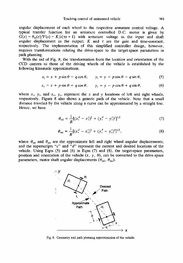
With the aid of Fig. 8, the transformation from the location and orientation of the CCD camera to those of the driving wheels of the vehicle is established by the following kinematic approximations.
X 1 = X q" p sin 0 -- q COS 0, Yl = Y -- P COS 0 -- q sin 0, (5)
x~ = x + p sin 0 + q cos 0, Yr = Y - P cos 0 + q sin 0, (6)
where xl, yl, and Xr, Yr, represent the x and y locations of left and right wheels, respectively. Figure 8 also shows a generic path of the vehicle. Note that a small distance traveled by the vehicle along a curve can be approximated by a straight line. Hence, we have
1 d 0.,, = ~ - [ ( X , -- X~) 2 + ( y l d -- y~)2],/2 (7) R
0,.r = l [ ( x d -- X~) 2 + ( y d _ y~)211/2, (8)
where 0m~ and Omr are the approximate left and right wheel angular displacements; and the superscripts " c " and " d " represent the current and desired locations of the vehicle. Using Eqns (5) and (6) in Eqns (7) and (8), the target-space parameters, position and orientation of the vehicle (x, y , 0), can be converted to the drive-space parameters, motor shaft angular displacements (0ml, 0mr).
-~y
Desired . ~ Path
L \ \ ",
Approximate \ ' , ~ f ~ \ Path . / ~ . ~ . \
> x
Fig. 8. Geometry and path planning approximation of the vehicle.

982 KOK-MENG LEE et al.
3.2. Digital tracking controller
The control objective here is to maneuver a vehicle to follow a prescribed path/ trajectory utilizing the visual feedback and modern digital control techniques. As control functions will be implemented using DSP and/or computers, we design the controllers in the discrete-time domain. First, we give a discretized state-space representation of the motor dynamics. The pole placement technique is then used to design the regulator in order to obtain the specified time response of the system. In the case where the vision system is used to measure only the vehicle's position, a reduced-order observer can be designed to estimate the vehicle's velocity necessary for full state feedback. Finally, a digital tracking filter is designed to generate the reference input for following a desired trajectory.
The discretized state-space model of the motor dynamics with the zero-order hold is given by
X ( k + 1) = A X ( k ) + Bu(k) (9)
y(k) = CX(k), (lO)
where
= L x 2 ( k ) J " A22J' B = B2 ' C = [1 0],
and where A12 . . . . ~ r(1 - e-T/~), A22 A e T.., B1 A K(T + Alz ), and B2 A K(1 - A22 ). T is the sampling period. Note that in Eqns (9) and (10), xl(k) and xz(k ) denote the angular displacement and angular velocity of the motor shaft respectively, u(k) represents the voltage input to the motor armature, and y(k) is the angular position output, all at the kth sampling instant. Based on the state-space representation and the seperation principle, the regulator and the observer for the discretized system are designed independently in the following.
3.2.1. Regulator with reduced-order observer. The time response specifications for the regulator design are denoted as: settling time = ts sec and maximum percent overshoot ~< Mp. These specifications of time response characteristics correspond to the desired pole locations o d -4-J'(/)d for the closed-loop system. Since the full state feedback control law is u(k )= -Krx (k ) , where Kr is the regulator gain matrix, the closed-loop system dynamics are then given by x(k + 1)= ,4x(k), where P, = A
- BK,. The regulator gain, Kr, can be determined by placing the poles of .A at the desired locations. In the case where a reduced-order observer is designed to estimate the angular velocity x2(k), the observer gain, L, , can be determined by placing the poles of Ae = A22 - L,A12 at a desired location, ~0.
3.2.2. Digital tracking filter. In the previous subsection, we outlined the design procedure for the digital state feedback regulator and reduced-order observer to achieve specified time response characteristics. Furthermore, in order to follow an arbitrary desired time-varying trajectory, we need to implement a digital tracking filter in the feedforward loop. The tracking filter design for the vehicle control system is based on the resultant closed-loop transfer function

Tracking control of unmanned vehicle 983
/(cl(z + z0) G d ( z ) --
(z - Od -- jtOd)(Z -- (~d ÷ jtad)' where Kd is the closed-loop gain constant and - z0 is a closed-loop zero. Notice that when the closed-loop zero, z -- -z0, is near the point ( - 1 ÷ j0) in the complex plane it is not advisable to perform direct zero-pole cancellation since the closed-loop zero, z - - - z 0 , becomes a pole of G~II(Z) which will generate an oscillatory reference signal. In this case, a zero phase error tracking filter (ZPETF) [11] can be designed. The following ZPETF generates the reference input for the closed-loop system consisting of the state feedback regulator and the reduced-order observer.
r(k) = Kt[a-lyd(k - 1) + aoYd(k) + alYd(k + 1) + aEYd(k ÷ 2)],
where r(k) denotes the reference input to the closed-loop system at the sampling instant k; ai(i-- - 1 , 0, 1, 2) is a constant coefficient to be determined based upon the motor parameters, controller design specifications, and sampling period; Yd(" ) represents the desired wheel angular displacement at the sampling instant ( . ) ; and Kt is the tracking filter gain which is determined experimentally.
4. INTEGRATED VISION-BASED TRACKING CONTROL SYSTEM
To demonstrate the principle and concept of vision tracking control of an un- manned vehicle, a prototype system has been designed and constructed. The laboratory prototype system consists of three basic subassemblies, a real-time flexible integrated vision system (FIVS), a three-wheeled autonomous vehicle, ViTra, and a DSP-based experimental testbed with a multimedia development environment.
4.1. Flexible integrated vision system (FIVS)
To form a feedback control loop and to enhance real-time path planning and trajectory tracking, a vehicle's position needs to be measured, then compared with the reference or desired position, and the resulting error fed back to the controller for appropriate control action. The ViTra solution to providing the feedback information is the FIVS [12], developed at Georgia Institute of Technology.
The FIVS, as its name refers, is a stand-alone machine vision system which integrates imaging sensors, control, illumination, signal processing, and data com- munication in a single unit. A prototype system is shown in Fig. 9. The FIVS has five basic functional modules: (1) an on-board DSP 56001 digital signal processor made by Motorola and the associated EEPROM, scratch RAM, and communication hardware; (2) a video head including an image sensor (TC-211 CCD by Texas Instruments), a high-bandwidth signal conditioning amplifier, a flash A/D converter, and a video RAM (VRAM); (3) an optic system with lens and illumination; (4) an off-line host- interface for system calibration, image analysis, and application-dependent software implementation; and (5) a real-time video record/playback for failure-mode detection.
An application development environment accompanying the hardware is developed to: (1) provide users with the flexibility to control the CCD array scanning, integration time, and illumination intensity; (2) allow image processing to be done on-board in real-time using the DSP; and (3) permit the process controller to setup

984 KOK-MENG LEE et al.
Fig. 9. Flexible integrated vision system (FIVS).
and calibrate the vision system, and to analyze any possible failure modes. Inter- grating the hardware and software, the FIVS is characterized by low cost, computa- tional efficiency, flexibility, and a friendly user interface.
Unlike the off-the-shelf conventional RS170-based systems, which strictly require pixel data to be stored in a video buffer before processing of the pixel data can commence, the FIVS design provides an option to completely bypass the video buffer. Thus the design offers a means to process and/or to store the digitized pixel data by directly transferring the A/D converter output to the DSP. For real-time vision-based object tracking and motion control system applications, the scheme represents a significant saving in time and video buffer size required for processing an image. The option to completely bypass the video buffer offers a potentially useful solution to eliminate the prerequisite of frame storage that is often required in off-the-shelf systems. Furthermore, this scheme completely eliminates the special hardware needed in acquiring the digitized pixel data for storage.
4.2. Prototype FIVS-guided autonomous vehicle
Maneuverability of a vehicle is essential to determine tracking performance of the vehicle since the effectiveness of control action depends on the vehicle's dynamics. For a quick and smooth dynamic response, the vehicle should have a smooth driving and transmission mechanism, must be able to turn freely in all directions, and contain minimum inertia yet enough weight to provide necessary contact force on the ground to prevent slipping.
To meet the vehicle design criteria, a three-wheel configuration with two rear driving wheels and a ball-joint-like universal front wheel is chosen for the autonomous vehicle, ViTra. The two rear driving wheels are geared to two D.C. motors controlled by power amplifiers. Use of two, instead of three or four, driving wheels simplifies the drive mechanism and the control of the vehicle, reduces the backlash, friction and stiction of the transmission system, and lowers the system inertia. The ball-joint-like front wheel allows the vehicle to maneuver in all directions without slip. Also, the universal front wheel eliminates the nonholonomic constraints inherent in conven- tional wheeled vehicles. The prototype design of the vehicle is shown in Fig. 10.
Tracking control of unmanned vehicle 985
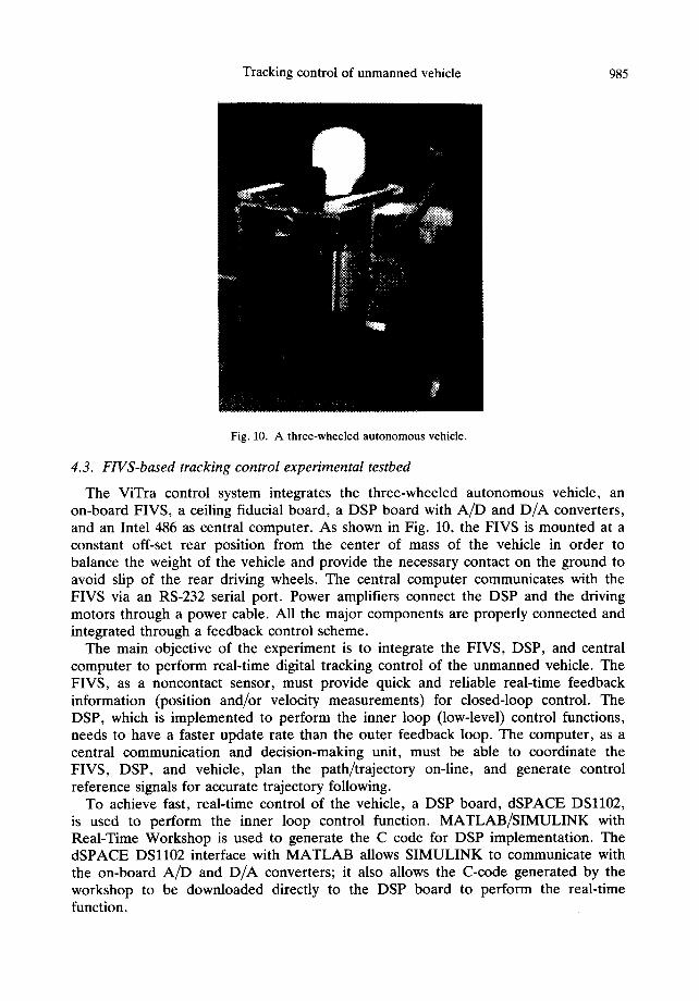
Fig. 10. A three-wheeled autonomous vehicle.
4.3. FIVS-based tracking control experimental testbed
The ViTra control system integrates the three-wheeled autonomous vehicle, an on-board FIVS, a ceiling fiducial board, a DSP board with A/D and D/A converters, and an Intel 486 as central computer. As shown in Fig. 10, the FIVS is mounted at a constant off-set rear position from the center of mass of the vehicle in order to balance the weight of the vehicle and provide the necessary contact on the ground to avoid slip of the rear driving wheels. The central computer communicates with the FIVS via an RS-232 serial port. Power amplifiers connect the DSP and the driving motors through a power cable. All the major components are properly connected and integrated through a feedback control scheme.
The main objective of the experiment is to integrate the FIVS, DSP, and central computer to perform real-time digital tracking control of the unmanned vehicle. The FIVS, as a noncontact sensor, must provide quick and reliable real-time feedback information (position and/or velocity measurements) for closed-loop control. The DSP, which is implemented to perform the inner loop (low-level) control functions, needs to have a faster update rate than the outer feedback loop. The computer, as a central communication and decision-making unit, must be able to coordinate the FIVS, DSP, and vehicle, plan the path/trajectory on-line, and generate control reference signals for accurate trajectory following.
To achieve fast, real-time control of the vehicle, a DSP board, dSPACE DSll02, is used to perform the inner loop control function. MATLAB/SIMULINK with Real-Time Workshop is used to generate the C code for DSP implementation. The dSPACE DSll02 interface with MATLAB allows SIMULINK to communicate with the on-board AiD and D/A converters; it also allows the C-code generated by the workshop to be downloaded directly to the DSP board to perform the real-time function.

986 KOK-MENG LEE et al.
To ensure accurate trajectory tracking, the outer position feedback loop is formed based on the FIVS measurement. As discussed in section 4.1, the FIVS by itself is an independent unit with an on-board DSP. All the functions of taking fiducial pictures, storing and analyzing images, and returning position and orientation information, are performed on-board in real-time. A ceiling fiducial board with the fiducial patterns uniquely designed as in section 2.1 is placed on a ceiling as the landmarks of the FIVS measurement system. Since the field of motion is restricted to 5 ft x 6 ft for the experiment, only 30 patterns are used for simplicity and computational efficiency. All the 30 patterns are properly spaced on the ceiling board of 5 ft × 6 ft, so that at least one complete pattern will be captured by the FIVS at each exposure. The experi- mental implementation of the designed fiducials is shown in Fig. 5. An Intel 486 (66 Hz) is used to coordinate the DSP and the FIVS, and to execute the functions such as path planning and reference signal generation for trajectory tracking. It is worth emphasizing that this experimental testbed aims at demonstrating the concepts of integrated vision-based motion control. Once the concepts are proven, modifica- tions of the existing prototype to eliminate the communication and power cables using wireless communication or radio-controlled devices and on-board battery power supply are relatively straightforward.
5. EXPERIMENTAL INVESTIGATION
Experiments are performed to calibrate the FIVS, to test the fiducial patterns, and to control the vehicle to track a specified circular path/trajectory.
5.1. Experimental parameters
The characteristics of the motors used to drive ViTra have been determined experimentally, and the results are summarized as: the gain K = 103.85 rad/sec. V and the time constant r = 0.05 sec. Based on the motor characteristics, a regulator is designed to achieve the desired time response specified by settling time ts = 0.1 sec and maximum percent overshoot Mp <~ 5. These specifications correspond to the desired closed-loop locations 0.9717 + j0.0275. The regulator gains which place the closed-loop pole at the desired locations are determined to be K r = [0.3979 0.0095]. A reduced-order observer is designed in the experiment to estimate the vehicle's velocity. The observer gain, L~, is determined by placing the poles of the estimation error system at the desired position, cr 0 = 0.5, and the result is found to be L~ = 486.7650. Implementation of the regulator and observer yields the following closed- loop z-transfer function:
Gd(z) = 0.002(z + 0.9937)
(z - 0.9717 - j0.0275)(z - 0.9717 + j0.0275)"
A zero phase error tracking filter with unit gain is then designed to be
r(k) = 1.0063yd(k -- 1) + 3.0695yd(k) + 0.9916yd(k + 1) -- 1.0582yd(k + 2).

T r a c k i n g c o n t r o l o f u n m a n n e d veh ic l e 987
5.2. FIVS static tests and calibration
For the experiment, the location of the ceiling fiducial board on which the patterns are placed is approximately 9.75 ft above the CCD lens (focal point) or H = 9.75 ft as shown in Fig. 1. The CCD is a fixed known distance behind the lens. This information is used to compute the scale factor between the actual and computed images in calibration.
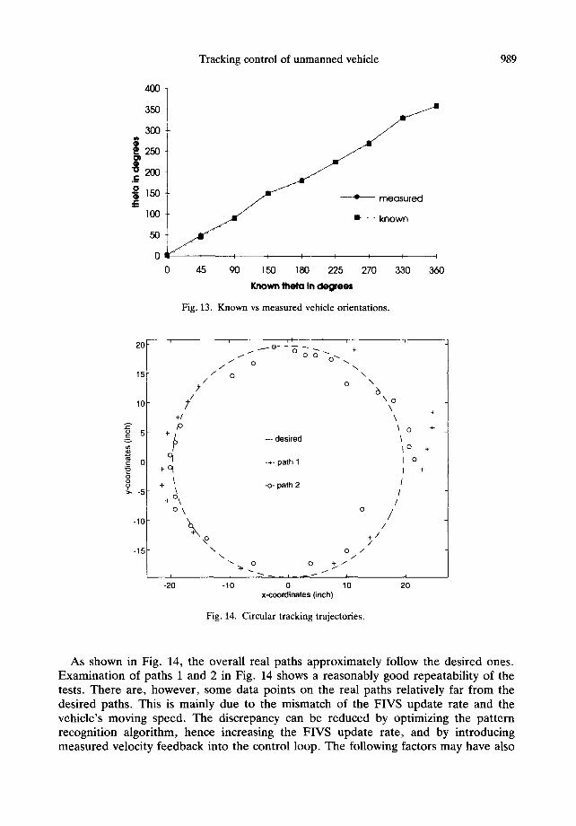
A calibration module, which operates on ".pcx" files and performs all the functions of segmentation and triangulation, is developed to calibrate the FIVS measurement system. Sample experiments were carried out for different vehicle positions and orientations around a predetermined trajectory. The characteristic trajectory was selected to be a circle of 20 in. radius centered at the geometric center of the ceiling board projection on the ground. Tables 1 and 2 list the known and measured vehicle positions. Figures 11-13 give the corresponding plots.
From Fig. 13, we observe that the measured orientations of the vehicle accurately match the known, world orientations. The average deviation from the known orientation is about 1.16 ° which is small considering the difficulty encountered in aligning the vehicle with the known coordinate system. The accuracy defined as the ratio of average deviation to workspace is about 0.32%. The measured (x, y) position data, as shown in Figs 11 and 12, are slightly off from the known positions. The
Table 1. Known and measured position data
Known positions Measured positions
x y 0 x y 0
1 - 1 9 - 4 0.00 -21 .19 - 5 . 9 3 - 3 . 4 4 2 - 6 19 0.00 - 8 . 9 9 15.25 0.64 3 20 4 0.00 16.69 1.88 - 0 . 0 7 4 15 - 1 2 0.00 12.34 -13 .58 1.32 5 2 - 1 9 0.00 - 1 . 0 9 -22 .21 0.52 6 - 7 - 1 8 0.00 -9 .41 -21 .00 -0 .31 7 - 1 5 - 1 2 0.00 -17 .75 -13 .58 -0 .31 8 0 0 0.00 -3 .01 - 1 . 7 5 0.46 9 22 - 1 8 0.00 18.88 -20 .18 - 0 . 8 0
10 - 2 0 21 0.00 -23 .65 17.50 -0 .31
Table 2. Known and measured orientation data
Known orientations Measured orientations
x y 0 x y 0
1 0.00 15 - 1 2 2.89 12.26 -13 .48 2 45.00 15 - 1 2 48.78 11.02 -11 .08 3 90.00 15 - 1 2 91.22 11.54 - 8 . 9 2 4 150.00 15 - 1 2 150.88 15.05 - 7 . 8 7 5 180.00 15 - 1 2 181.52 16.95 - 9 . 0 5 6 225.00 15 - 1 2 225.00 16.55 -12 .46 7 270.00 15 - 1 2 271.41 16.83 -13 .91 8 330.00 15 - 1 2 331.22 13.96 -14 .52 9 360.00 15 - 1 2 359.93 12.23 -12 .68

988 KOK-MENG LEE et al.
t,I. u
25
20 :
15~
10,
5 ,
O ,
-5-20
-10
-15 •
-19
-20 i ~ / j
-25 gr-
• 1 1 0 measured
known , ~ , ~ /
~ m : • I
-15 -7 -~ ~ 2 15 20 22
Known x in inches
Fig. l 1. Known vs measured vehicle x-positions.
25
20 o measured I j ~
15 ~ • known
10 . / /
¢ -
U
.c _5_119 -18 -18 -12 -12 19 21
-10 ' /
-- 1 5 I / [ ~ -- ~
-25 -
Known y in inches
Fig. 12. Known vs measured vehicle y-positions.
average position deviation from the true position is about 2.92 and 2.63 in. with the accuracies of 4.86 and 3.65% for the (x, y) coordinates, respectively. The discrepancy between the known and the measured positions is due to the level of the CCD lens and the lighting conditions etc. The CCD lens must be perfectly leveled (pointing vertically to the ceiling pattern board) to ensure precise measurement. Overall, the pattern recognition algorithm and the fiducial patterns worked fairly well for the experiment.
5.3. Trajectory tracking results and discussion
The control algorithms designed in sections 3.2 and 5.1 are implemented through host and DSP programs to track a desired circular path with radius of 20 in. A number of trajectory tests are performed, and two typical paths are recorded and plotted in Fig. 14.
Tracking control of unmanned vehicle
400
350
300
| 250
m
100 ~ m- - - known
50 ~ " "
Off" + I I I I I I I
0 45 90 1,50 180 225 270 330 360
Known ll1@la In d e g r e e s
Fig. 13. Known vs measured vehicle orientations.
989
20
15
10
. lZ
o:ii -15
/
/ +I ,o
+q
+ \
i LI I i
0 0 u ~ 0
/ 0 \ 0
- - desired
-+- path 1
-o- path 2
+ o k o\
\
t -20
0 J
o + / /
-10 o lO x-coordinates (inch)
Fig. 14. Circular tracking trajectories.
\
6 \o \ \
\ o \ ~o
I o
l / / /
/ /
+ / /
/
I
20
+
+
+
+
As shown in Fig. 14, the overall real paths approximately follow the desired ones. Examination of paths 1 and 2 in Fig. 14 shows a reasonably good repeatability of the tests. There are, however, some data points on the real paths relatively far from the desired paths. This is mainly due to the mismatch of the FIVS update rate and the vehicle's moving speed. The discrepancy can be reduced by optimizing the pattern recognition algorithm, hence increasing the FIVS update rate, and by introducing measured velocity feedback into the control loop. The following factors may have also
990 K O K - M E N G L E E et al.
contributed to the trajectory discrepancy: (1) unmodeled friction, (2) ceiling board not perfectly leveled, and (3) approximation in path planning. It is expected that the discrepancy can be further minimized by improved modeling and more sophisticated system calibration and controller design.
6. CONCLUSIONS
A practical vision-based tracking control system for an unmanned vehicle, ViTra, has been presented in this paper. Unlike conventional machine vision systems, ViTra uses a DSP-based flexible integrated vision system (FIVS) which is characterized by low cost, computational efficiency, flexibility, and a friendly user interface. The uniquely designed fiducial patterns and corresponding pattern recognition algorithm better facilitated the FIVS machine vision system. The unique design of ViTra improved the maneuverability of the vehicle, and eliminated the nonholonomic constraints of the front wheel inherent in traditional wheeled vehicles. The DSP implementation of the digital controllers and observer designed in the paper showed the practicability of using modern control techniques to enhance the system perform- ance. Practical control issues such as simplifying nonlinear dynamics and dealing with nonholonomic constraints have also been addressed in the paper.
A number of static tests demonstrated the FIVS's precision measurement of the vehicle's position and allowed accurate calibration of the FIVS. Sample circular trajectory tracking experiments illustrated the possibility of using the FIVS in real-time tracking applications of unmanned vehicles. Research work is currently being directed toward optimizing the fiducial patterns and pattern recognition algorithm, further improving the maneuverability of the vehicle, and conducting various trajectory tracking tests.
Acknowledgements--This work is partially supported by the National Science Foundation under the grant number DDM-8958383 and the CIMS/AT&T Intelligent Mechatronics Laboratory at Georgia Institute of Technology. Contributions to the initial phase of this work made by Vikram Kapila, Dan Ezenekwe, Tam Cam, and Xiao Wu are greatly appreciated.
REFERENCES
I. Lee K. M., Flexible part-feeding system for machine loading and assembly. Part I. A state-of-the-art survey. Part II. A cost-effective solution. Int. J. Prod. Econ. 25, 141-168 (1991).
2. Harris C. J. and Charnley D., Intelligent autonomous vehicles: recent progress and central research issues. Comput. Contr. Engng Jl July, 164-171 (1992).
3. Thorpe C., Stentz A. and Sharer S., Architecture for Autonomous Vehicle Navigation. AIAA/ACM/ NASA/IEEE Computers in Aerospace V Conference, pp. 22-27, Long Beach, CA, October (1985).
4. Wargocki F. E. and Ray A. J., Retroreflective field tracker. SPIE Vol. 501, State-of-the-art Imaging Arrays and Their Applications, San Diego, CA, August (1984).
5. Lee K. M. and Qian Y. F., Development of a flexible intelligent control for target pursuit. Recent Advances in Mechatronics, ICRAM '95, Istanbul, Turkey, August (1995).
6. Bose B. C. and Amir I., Design of fiducials for accurate registration using machine vision. 1EEE Trans. Pattern Anal. Machine Intell. 12, 1196-1200 (1990).
7. Lee K. M. and Li D., Retroreflective vision sensing for generic part presentation. J. Robotic Syst. 8(I), 55-73 (1991).
8. Fu K. S. and Rosenfeld A., Pattern recognition and computer vision. Computer 17(10), 274-282 (1984).
Tracking control of unmanned vehicle 991
9. Lee K. M. and Janakiraman S., A model-based vision algorithm for real time flexible part feeding and assembly. Applied Machine Vision Conference '92, Atlanta, GA, June (1992).
i0. Haralick R. M. and Shapiro L. G., Image segmentation techniques. Comput. Vision, Graphics, Image Proc. 29(1), 100-132 (1985).
11. Tomizuka M., Zero phase error tracking algorithm for digital control. J. Dynam. Syst., Meas., Control 109, 65-68 (1987).
12. Lee K. M. and Blenis R. Jr, Design concept and prototype development of a flexible integrated vision system. J. Robotic Syst. 11(5), 387-398 (1994).