real-time system management information program data ... · a real-time system management...
TRANSCRIPT

Real-Time System Management Information Program Data Exchange Format Specification
August 2013

Produced by DTFH61-06-D-00004 Real-Time System Management Information Program Data Exchange Format Specification Implementation and Guidance U.S. Department of Transportation
Notice
This document is disseminated under the sponsorship of the U.S. Department of Transportation in the interest of information exchange. The U.S. Government assumes no liability for the use of the information contained in this document.
The U.S. Government does not endorse products or manufacturers. Trademarks or manufacturers’ names appear in this report only because they are considered essential to the objective of the document.
Quality Assurance Statement
The Federal Highway Administration (FHWA) provides high-quality information to serve Government, industry, and the public in a manner that promotes public understanding. Standards and policies are used to ensure and maximize the quality, objectivity, utility, and integrity of its information. FHWA periodically reviews quality issues and adjusts its programs and processes to ensure continuous quality improvement.

Technical Report Documentation Page 1. Report No.
FHWA-HOP-13-047 2. Government Accession No.
3. Recipient’s Catalog No.
4. Title and Subtitle
Real-Time System Management Information Program Data Exchange Format Specification
5. Report Date
August 2013
6. Performing Organization Code
7. Author(s)
Consensus Systems Technologies (“ConSysTec”) and Cambridge Systematics, Inc.
8. Performing Organization Report No.
9. Performing Organization Name And Address
Consensus Systems Technologies Cambridge Systematics, Inc. 17 Miller Avenue / POB 517 4800 Hampden Lane, Suite 800 Shenorock, NY 10587 Bethesda, MD 20814
10. Work Unit No. (TRAIS) 11. Contract or Grant No.
DTFH61-06-D-00004 12. Sponsoring Agency Name and Address
U.S. Department of Transportation Federal Highway Administration Office of Operations 1200 New Jersey Ave., SE Washington, DC 20590
13. Type of Report and Period Covered
14. Sponsoring Agency Code
HOP
15. Supplementary Notes
Mr. Robert Rupert, Federal Highway Administration, GTM 16. Abstract
Section 1201 of SAFETEA-LU, published in August 2005, instructed the Secretary of Transportation to establish a real-time system management information program to provide, in all states, the capability to monitor, in real-time, the traffic and travel conditions of the major highways of the United States and to share that information to improve the security of the surface transportation system, to address congestion problems, to support improved response to weather events and surface transportation incidents, and facilitate national and regional highway traveler information. In response to these requirements, U.S. Code of Federal Regulations (CFR) 23 Part 511 was developed. Title 23 CFR Part 511 requires each state to establish and operate a Real-Time System Management Information Program (RTSMIP) capable of gathering and making available the data for traffic and travel conditions. However, Title 23 CFR 511 does not require the dissemination of real-time information in any particular manner, only that the states make the information available. It also does not require states to apply any particular technology, technology-dependent application, or business model for collecting, processing and disseminating information. As a result, development of a Data Exchange Format Specification (DXFS) and implementation guidance was initiated to support the need of states for a specification that satisfies the essential elements of the rule. In 2011, U.S. DOT began development of the Data Exchange Format Specification (DXFS) to facilitate the development of interoperable real-time traffic and travel information between public agencies, with other public agencies, and with private entities. The DXFS has been developed to assist users to specify and then develop an RTSMIP implementation. 17. Key Words
DXFS, RTSMIP, real-time information 18. Distribution Statement
No restrictions. 19. Security Classif. (of this report)
Unclassified 20. Security Classif. (of this page)
Unclassified 21. No. of Pages
132 22. Price
N/A
Form DOT F 1700.7 (8-72) Reproduction of completed page authorized


iii
TABLE OF CONTENTS
EXECUTIVE SUMMARY ...........................................................................................................1
REAL-TIME SYSTEM MANAGEMENT INFORMATION PROGRAM (RTSMIP) ............................................................................................................................. 1
DATA EXCHANGE FORMAT SPECIFICATION (DXFS) .......................................... 1
USERS OF THE DXFS ....................................................................................................... 2
1. INTRODUCTION.................................................................................................................3
1.1 SCOPE ......................................................................................................................... 3
1.2 REFERENCES ............................................................................................................ 3
1.3 GENERAL STATEMENTS ...................................................................................... 4
1.4 TERMS ........................................................................................................................ 4
1.5 ABBREVIATIONS ..................................................................................................... 5
2. CONCEPT OF OPERATIONS ...........................................................................................9
2.1 INTRODUCTION....................................................................................................... 9
2.2 BACKGROUND, OBJECTIVES, AND CURRENT SYSTEM OR SITUATION ....................................................................................................................... 10
2.2.1 Background ................................................................................................................ 10
2.2.2 Objectives of the DXFS .............................................................................................. 11
2.2.3 Description of the Current Situation ......................................................................... 12
2.2.4 Stakeholders ............................................................................................................... 14
2.3 REFERENCE PHYSICAL ARCHITECTURE .................................................... 15
2.3.1 Transportation Agency Systems................................................................................. 17
2.3.2 Transit Agency Systems ............................................................................................. 18
2.3.3 Peer Transportation Agency Systems ........................................................................ 18
2.3.4 Public Safety Agency Systems.................................................................................... 18
2.3.5 Private Data Collection Organization Systems ......................................................... 18
2.3.6 Travelers ..................................................................................................................... 18
2.3.7 Public Traveler Information Provider Systems ......................................................... 18
2.3.8 Private Third Party Providers Systems ...................................................................... 18
2.3.9 Other Public Agencies Systems.................................................................................. 19
2.4 ARCHITECTURAL NEEDS ................................................................................... 19
2.5 FEATURES ............................................................................................................... 19
2.5.1 Introduction to User Needs ........................................................................................ 19

Table of Contents, continued
iv
2.5.2 Travel Time User Needs ............................................................................................. 20
2.5.3 Incident Information User Needs .............................................................................. 21
2.5.4 Construction Information User Needs ...................................................................... 22
2.5.5 Weather Information User Needs .............................................................................. 23
2.5.6 Transit Information User Needs ................................................................................ 24
2.5.7 Roadway Network Information Needs ...................................................................... 25
2.5.8 Connection Management User Needs ....................................................................... 25
2.6 SECURITY ................................................................................................................ 25
2.7 OPERATIONAL POLICIES AND CONSTRAINTS ........................................... 25
2.8 RELATIONSHIP TO THE NATIONAL ITS ARCHITECTURE ...................... 27
2.8.1 Entities ........................................................................................................................ 27
2.8.2 Interfaces .................................................................................................................... 28
2.9 OPERATIONAL SCENARIOS .............................................................................. 33
2.9.1 Introduction to Operational Scenarios ...................................................................... 33
2.9.2 Managing the Surface Transportation System Using Real Time Information ....... 36
2.9.3 Maintaining the Surface Transportation System Using Real Time Road Weather Information .............................................................................................................. 39
2.9.4 Share information with the traveling public ............................................................. 40
2.9.5 Share information with state and local government agencies .................................. 42
2.9.6 Share Information with Public Traveler Information Providers ............................. 45
2.9.7 Share information with private third party providers ............................................... 46
3. FUNCTIONAL REQUIREMENTS ..................................................................................49
3.1 TUTORIAL ............................................................................................................... 49
3.2 SCOPE OF THE REQUIREMENTS ..................................................................... 50
3.3 NEEDS TO REQUIREMENTS TRACEABILITY MATRIX (NRTM) ............. 50
3.3.1 Notation ...................................................................................................................... 51
3.3.2 Needs to Requirements Traceability Matrix (NRTM) Table .................................... 53
3.4 ARCHITECTURAL REQUIREMENTS ............................................................... 54
3.4.1 Connection Management ........................................................................................... 54
3.4.2 Support Request-Response ......................................................................................... 55
3.4.3 Support Subscription-Publication ............................................................................. 56
3.4.4 Support Error Handling Report ................................................................................ 56
3.5 FUNCTIONAL REQUIREMENTS ........................................................................ 56
3.5.1 Provide Information on Organizations and Centers................................................. 56

v
3.5.2 Events Information Sharing ...................................................................................... 57
3.5.3 Share Roadway Network Data ................................................................................... 77
3.5.4 Provide Device Inventory and Status. ........................................................................ 90
3.5.5 Transit Related Requirements ................................................................................. 108
3.5.6 Weather Alert Requirements .................................................................................... 115
3.6 PERFORMANCE REQUIREMENTS ................................................................. 117
3.6.1 Message Transmission Time – Publication Updates .............................................. 117
3.6.2 Response Time .......................................................................................................... 117
4. DESIGN REFERENCE ...................................................................................................119
4.1 DESIGN SCOPE ..................................................................................................... 119
4.2 REQUIREMENTS TRACEABILITY MATRIX (RTM) ................................... 119
4.2.1 Requirement ID and Requirement .......................................................................... 119
4.2.2 Data Concept Type (DC Type) ................................................................................. 119
4.2.3 DC Instance Name, DC ID, and DC Class Name ................................................... 119
4.2.4 Comment ................................................................................................................... 120
4.2.5 RTM Table Selection ................................................................................................ 120


vii
LIST OF TABLES
Table 1. Terms and Definitions..................................................................................................................... 4 Table 2. Abbreviations. ................................................................................................................................. 6 Table 3. Minimum Service Quality Levels. ................................................................................................ 16 Table 4. Mapping to National ITS Architecture Entities. ........................................................................... 27 Table 5. Private Data Collection Organization to Transportation Agency Interface. ................................. 28 Table 6. Transportation Agency to Peer Transportation Agency. .............................................................. 29 Table 7. Transportation Agency to Public Traveler Information Provider. ................................................ 30 Table 8. Transportation Agency to Private Third Party Provider. .............................................................. 30 Table 9. Public Traveler information Provider to Private Third Party Provider. ........................................ 31 Table 10. Transportation Agency to Travelers. .......................................................................................... 32 Table 11. Public Traveler Information Provider to Travelers. .................................................................... 32 Table 12. Transportation Agency to Other Public Agency. ........................................................................ 33 Table 13. Other Public Agency to Transportation Agency. ........................................................................ 33 Table 14. Actor Definitions and Associated Stakeholders. ......................................................................... 34 Table 15. Operational Scenario – Using Real Time Information. .............................................................. 36 Table 16. Operational Scenario - Using Real Time Weather Information .................................................. 39 Table 17. Operational Scenario – Sharing Information with Traveling Public. ......................................... 40 Table 18. Operational Scenario – Sharing Information with State and Local Government Agencies ........ 42 Table 19. Operational Scenario – Sharing Information with Public Traveler Information Providers. ....... 45 Table 20. Sharing Information with Private Third Party Providers. ........................................................... 46 Table 21. Conformance Symbols. ............................................................................................................... 51 Table 22. Predicate Notations. .................................................................................................................... 52 Table 23. Predicates. ................................................................................................................................... 52
LIST OF FIGURES
Figure 1. Diagram. RTSMIP Context Diagram. ......................................................................................... 17


1
EXECUTIVE SUMMARY REAL-TIME SYSTEM MANAGEMENT INFORMATION PROGRAM (RTSMIP) Section 1201 of the Safe, Accountable, Flexible, Efficient Transportation Equity Act: A Legacy for Users (SAFETEA-LU), published in August 2005, instructed the Secretary of Transportation to “… establish a real-time system management information program (RTSMIP) to provide, in all states, the capability to monitor, in real-time, the traffic and travel conditions of the major highways of the United States and to share that information to improve the security of the surface transportation system, to address congestion problems, to support improved response to weather events and surface transportation incidents, and facilitate national and regional highway traveler information.” Additional information about Section 1201 is available at http://www.ops.fhwa.dot.gov/1201/.1
In response to these requirements, U.S. Code of Federal Regulations (CFR) 23 Part 511 was developed. Title 23 CFR Part 511 requires each state to establish and operate a Real-Time System Management Information Program (RTSMIP) as part of its Intelligent Transportation System (ITS)capable of gathering and making available the data for traffic and travel conditions. However, Title 23 CFR 511 does not require the dissemination of real-time information in any particular manner, only that the states make the information available. It also does not require states to apply any particular technology, technology-dependent application, or business model for collecting, processing and disseminating information. As a result, development of a Data Exchange Format Specification (DXFS) and implementation guidance was initiated to support the need of states for a specification that satisfies the essential elements of the rule. DATA EXCHANGE FORMAT SPECIFICATION (DXFS) In 2011, U.S. DOT began development of the Data Exchange Format Specification (DXFS) to facilitate the development of interoperable real-time traffic and travel information between public agencies, with other public agencies, and with private entities.
A primary objective of the DXFS is to establish a standards-based specification of key RTSMIP interfaces. To align with the objective the scope of the DXFS is the set of interfaces used to send traffic, transit, transportation-related weather, and traveler information from one agency to another. The provision of this data directly to travelers is not part of the scope of the specification. While the DXFS covers all the information defined in Rule 23 CFR 511, the scope of the DXFS has been expanded beyond the information defined in the rule to include transit information and additional traffic information that is relevant to the exchange of data between agencies (and other parties). The DXFS is a specification that can be used to define the
1 Real-Time System Management Information Program – FHWA Operations,
http://www.ops.fhwa.dot.gov/1201/.

2
information exchanges across a system-to-system interface, thus providing interoperability of systems that implement the DXFS. The DXFS does not specify communication protocols, but it does refer to existing standardized protocols that can be used for transferring the data. USERS OF THE DXFS The DXFS has been developed to assist the following groups of users to specify and then develop an RTSMIP implementation:
• Transportation Agencies. This group includes state DOTs and regional transportation
related organizations (e.g., a municipal DOT or Public Works or a transit agency) that are developing systems that implement aspects of the RTSMIP.
• Public Safety Agencies. This group includes state, county, or local public safety agencies that develop systems that support RTSMIP.
• Traveler Information Organizations (Public or Private). This group includes providers of traveler information whether public or private that are involved in the development of systems that support RTSMIP.
• Development Contractors. This group includes contractors who have been hired by transportation or public safety agencies to develop procurement packages that would specify aspects of RTSMIP, or contractors who have been selected to perform the development of RTSMIP related project.

3
INTRODUCTION 1. 1.1 SCOPE This document describes the Data Exchange Format Specification (DXFS) for specifying the implementation of a Real-Time System Management Information Program (RTSMIP) at a state or regional level. The RTSMIP provides access to traffic and travel conditions information, prepared by State DOTs and other responsible agencies operating transportation infrastructure, to other public agencies, the traveling public, and entities who may deliver value-added information products. The DXFS is a detailed specification of the key interfaces defined as part of the RTSMIP. The DXFS is not a new ITS standard; rather it is a specification of existing ITS standards that can address a set of user needs which support a RTSMIP. 1.2 REFERENCES The references cited or used in this document are listed below. 1. Institute of Electrical and Electronics Engineers (IEEE) Standard 1362-1998 IEEE Guide for
Information Technology, System Definition, Concept of Operations (ConOps) Document. 2. Cambridge Systematics Inc. Report: Real-Time System Management Information Program
(RTSMIP) Data Exchange Format Specification, and Implementation Guidance, User Needs Interview Summary, Technical Memorandum, January 31, 2012.
3. Federal Highway Administration 23 CFR Part 511, Real-Time System Management Information Program, November 8, 2010.
4. American Association of State Highway and Transportation Officials (AASHTO) and Institute of Transportation Engineers (ITE). Traffic Management Data Dictionary (TMDD) Standard for the Center to Center Communications. Version 3.03a. Volume II, Design Content. August 8, 2013.
5. Technical Committee CEN/TC 278 “Road transport and traffic telematics”. Draft European Standard Public transport — Service interface for real-time information relating to public transport operations — Part 1: Context and framework, prEN_15531-1_(E)-SIRIv2.0 Part1-v05.doc STD Version 2.1c, 2012-01.
6. Technical Committee CEN/TC 278 “Road transport and traffic telematics”. Draft European Standard Public transport — Service interface for real-time information relating to public transport operations — Part 3: Functional service interfaces, prEN_15531-3_(E)-SIRIv2.0 Part3-v06.doc STD Version 2.1c, 2012-01.
7. APTA TCIP-S-001 3.0.6, APTA Draft Standard for Transit Communications Interface Profiles, Version 3.0.6 Volume II TCIP Data and Dialog Definitions.
8. OASIS Emergency Management Technical Committee, OASIS Common Alerting Protocol, v. 1.1, October 2005.
9. National Weather Service, NWS Watches, Warnings, and Advisories using CAP and ATOM based Formats, Service Description Document.

4
10. NTCIP 2306 version 01 National Transportation Communications for ITS Protocol Application Profile for XML Message Encoding and Transport in ITS Center-to-Center Communications, December 2008.
11. SAE-J2266 Location Referencing Message Specification (LRMS), SAE International, October 2004.
1.3 GENERAL STATEMENTS Not applicable. 1.4 TERMS For the purposes of this document, the following terms and definitions apply.
Table 1. Terms and Definitions.
Term Description
23 CFR 511 FHWA rule defining the Real-Time System Management Information Program. This rule establishes minimum parameters and requirements for States to make available and share traffic and travel conditions information via real-time information programs.
Aftermarket Safety Device
A connected device that may operate while it is mobile, but which is not connected to the data bus of a vehicle.
Average Speed
The summation of the instantaneous or spot-measured speeds at a specific location of vehicles divided by the number of vehicles observed (MUTCD Section 1A.13)
Block The daily sequence of revenue and non-revenue trips assigned to a transit vehicle in revenue service from pull-out to pull-in.
Connected Vehicle RSU
Any roadside unit device used to transmit to or receive messages from similar devices located on vehicles.
Connected Vehicle
A vehicle containing an on-board unit or aftermarket safety device. .
Public Safety Center
Public Safety centers, as discussed in the context of RTSMIP user needs include 911 centers, PSAPs, and other first responder dispatch functions. Under certain conditions the EMC could include Emergency Operations Centers.

5
Table 1. Terms and Definitions.
Term Description
Environmental Conditions Data
Current road conditions (e.g., surface temperature, subsurface temperature, moisture, icing, treatment status) and surface weather conditions (e.g., air temperature, humidity, air pressure, wind speed, precipitation, visibility) as measured and reported by fixed and/or mobile environmental sensors and aggregated by the data collector. Attributes relating to the data collection (and aggregation) are also included.
Identifier A unique number assigned to an item (bus, employee, trip, stop, stop point etc.) to provide a short and uniform way to reference that item, as distinct from all other items of the same type.
Intelligent Transportation Systems (ITS)
Systems that apply modern technology to transportation problems. Another appropriate meaning of the ITS acronym is integrated transportation systems, which stressed that ITS systems will often integrate components and users from many domains, both public and private.
Node A point within a network. Nodes provide a geographic location that can represent the beginning and end points of a link, location of a device, intersection, or location of an event.
On-Board Unit
A vehicle mounted device used to transmit and receive a variety of message traffic to and from other connected devices (other OBUs and RSUs). Among the message types and applications supported by this device are vehicle safety messages, a primary subject of this standard, used to exchange information on each vehicle's dynamic movements for coordination and safety.
Peer Transportation Agencies
Since the RTSMIP is meant primarily for state DOTs and transportation agencies in large metropolitan areas, peer transportation agencies would include state DOTs, as well as regional and municipal transportation agencies
Planned Event A planned event is a construction event or special event that is projected to occur and may include timeline schedule elements.
Roadway Link A roadway between two nodes.
Service Alert Transit service alerts provide updates whenever there is disruption on the network, including route delays or route cancellations.
1.5 ABBREVIATIONS The abbreviations used in this Document are defined as follows:

6
Table 2. Abbreviations.
Abbreviation Description
AVL Automatic Vehicle Location
CAP Common Alerting Protocol
CCTV Closed Circuit Television
ConOps Concept of Operations
DMS Dynamic Message Sign
DXFS Data eXchange Format Specification
EM Emergency Management Subsystem
HAR Highway Advisory Radio
ISPS Information Service Provider Subsystem
MTA Metropolitan Transportation Authority
MTC Metropolitan Transportation Commission
NRTM Needs to Requirements Traceability Matrix
OBU On-board Unit
PSAP Public Safety Answering Point
RDS Radio Data System
RS Roadside Subsystem
RSU Roadside Unit
RTSMIP Real-Time System Management Information Program
SAFETEA-LU Safe, Accountable, Flexible, Efficient Transportation Equity Act: A Legacy for Users
SIRI Service interface for real-time information relating to public transport operations
TCIP Transit Communications Interface Profile
TMC Traffic Management Center
TMDD Traffic Management Data Dictionary

7
Table 2. Abbreviations.
Abbreviation Description
TMS Traffic Management Subsystem
TPEG Transport Protocol Experts Group
TRMS Transit Management Subsystem
VS Vehicle Subsystem


9
CONCEPT OF OPERATIONS 2. This section describes the Concept of Operations (ConOps) for the DXFS. A ConOps describes the ways a proposed system will be used from the users’ perspective. The ConOps is one of the first key outputs of the systems engineering process and forms the basis for the definition of requirements. The ConOps stage of the systems engineering process is used to ensure that the system developers document a thorough understanding of the users’ needs. The ConOps provides the reader with a detailed description of the scope of the DXFS, the user needs which the DXFS will address, and the operational scenarios that consider the center to center interfaces that will be a part of the DXFS. Readers will find this section useful for understanding the type of information that will be a part of the DXFS. It serves as the starting point in the procurement and specification process. Procurers and specification writers, such as the transportation agencies, can become familiar with each capability addressed by the DXFS and determine whether that capability is appropriate for their implementation. If it is, then their implementation will require the capability and all of the mandatory requirements related to that capability. 2.1 INTRODUCTION A concept of operations describes a proposed system from the users' perspective. Typically, a concept of operations is used on a project to ensure that the system developers understand the users' needs. Within the RTSMIP effort, the concept of operations documents the scope of the DXFS, and presents a user’s view of the program. The concept of operations also serves as the starting point for agencies to select those features that may be appropriate for a specific procurement that will use the DXFS. The concept of operations starts with a discussion of the background surrounding the development of the DXFS, the objectives of the DXFS, and the current situation and issues that have led to the need to deploy systems within the scope of the standard and to the development of the standard itself. This discussion permits both potential users and system developers to understand the situation. The concept of operations then documents key aspects of the proposed system, including: • Reference Physical Architecture (Section 2.3) – The reference physical architecture defines
the overall context of the proposed system and defines which specific interfaces are addressed.
• Architectural Needs (Section 2.4) – The architectural needs discuss issues and needs relative to the system architecture. Because the RTSMIP does not define any particular system architecture, this section is not used.
• Features (Section 2.5) – The features identify and describe the various functions that users may want the system to perform. These features are derived from the high level user needs identified

10
in the problem statement but are refined and organized into a more manageable structure that forms the basis of the traceability table contained in Section 3 (Functional Requirements).
Architectural needs and features are collectively called “user needs”. In Section 3, these user needs are traced to the various functional requirements of the RTSMIP environment. Basic systems engineering requires that:
• Each user need traces to one or more functional requirement(s). • Each functional requirement derives from at least one user need.
This traceability is shown in the Needs to Requirements Traceability Matrix (NRTM) in Section 3.3.3. The DXFS is intended to support a broad range of prospective implementations. Within the NRTM, each user need and requirement is identified as mandatory, optional, or conditional, and users of this standard may complete the NRTM to clearly define unique aspects of their implementation. Within the DXFS, items marked mandatory are those that relate to the most basic functionality of providing real time traffic, transit, or traveler information. For specific implementations, the user identifies those optional or conditional needs appropriate for a specific implementation. The concept of operations concludes by: • Describing the extent to which policies or constraints relative to the operational environment
have a direct impact on the implementation of this standard (Section 2.7). • Providing a description of how the interfaces to be described in the DXFS relate to the
National ITS Architecture (Section 2.8). • Presenting operational scenarios that demonstrate how a proposed system that is part of an
RTSMIP and uses the DXFS should operate and interact with its users under a various sets of specific circumstances (Section 2.9).
2.2 BACKGROUND, OBJECTIVES, AND CURRENT SYSTEM OR SITUATION This section provides a discussion of the background that lead to the creation of the DXFS, the objectives of the DXFS, and an overview of the current situation regarding real time traveler information. 2.2.1 Background Section 1201 of the Safe, Accountable, Flexible, Efficient Transportation Equity Act: A Legacy for Users (SAFETEA-LU), published in August 2005, instructed the Secretary of Transportation to “… establish a real-time system management information program (RTSMIP) to provide, in all states, the capability to monitor, in real-time, the traffic and travel conditions of the major highways of the United States and to share that information to improve the security of the surface transportation system, to address congestion problems, to support improved response to weather events and surface transportation incidents, and facilitate national and regional highway traveler information.”

11
A Final Rule was published on November 8, 2010, establishing the provisions and parameters for the Real-Time System Management Information Program to be established by State DOTs, other responsible agencies, and partnerships with other commercial entities. The Program is to be established on all Interstate routes within 4 years (November 8, 2014) and on other significant roadways as identified by the States and local agencies within 6 years (November 8, 2016). In response to these requirements, U.S. Code of Federal Regulations (CFR) 23 Part 511 was developed. 23 CFR Part 511 requires each state to establish and operate a RTSMIP as part of its Intelligent Transportation System (ITS). Title 23 CFR 511 does not require the dissemination of real-time information in any particular manner, only that the states make the information available. It also does not require states to apply any particular technology, technology-dependent application, or business model for collecting, processing and disseminating information. Additional information about Section 1201 is available at http://www.ops.fhwa.dot.gov/1201/2. Section 1201 also required the Secretary to establish data exchange formats to ensure that the data provided by highway and transit monitoring systems, including statewide incident reporting systems, can readily be exchanged across jurisdictional boundaries; facilitating nationwide availability of information. In 2011, U.S. DOT began development of this DXFS to facilitate the development of interoperable real-time traffic and travel information between public agencies, with other public agencies, and with private entities. 2.2.2 Objectives of the DXFS The objective of the DXFS is to create a standards-based definition of key RTSMIP interfaces. This approach addresses three major issues that threaten center to center exchanges of real-time information: • More than one standard (as well as proprietary solutions) may exist to encode and define the
same information. For example incident information could be defined by data concepts from Traffic Management Data Dictionary (TMDD) or from IEEE 1512- Standard for Common Incident Management Message Sets for use by Emergency Management Centers. An agreement must be reached between each pair of agencies or regionally as to what encoding, meaning (derivation), and logical relationships are to be used to describe the information for information exchanges to be effective.
• Each agency may have its own goals and objectives for the data it collects, and the data quality attributes (metadata) will likely be adjusted to meet the intended local uses of the data. Data with inadequate quality attributes may be of little or no value to agencies in other
2 Real-Time System Management Information Program – FHWA Operations, http://www.ops.fhwa.dot.gov/1201/ May, 2013.

12
regions. There is no agency/entity expectation as to data quality received from other entities, nor is there a uniformly accepted method for representing data quality (metadata).
• There may be competing methods for communicating encoded transportation information between entities. While today structured implementations of XML are popular over the Internet, there are still organizations that have substantial investments in ASN.1.
The RTSMIP DXFS has been developed to eliminate all the above uncertainties and thus measurably accelerate the investment in and deployment of ITS systems that can share real-time traffic and travel conditions information effectively between public entities, or between public and private entities. The RTSMIP DXFS has been developed with consideration of the many stakeholders’ independent goals and objectives. A systems engineering process of verification and especially validation at each key stage of the RTSMIP DXFS development was employed to achieve this stakeholder focused result. 2.2.3 Description of the Current Situation The current situation regarding collection, processing, and dissemination of real time information is summarized below.
Data Collection 2.2.3.1 Collection of real time data is occurring at almost all transportation agencies. The primary difference between agencies is the scope of the collection. Almost every agency collects freeway speed data. In most cases this is done using agency field equipment, but a subset of agencies purchase the speed data from private companies. Most state agencies have speed collection capabilities on the freeways near the major urban areas of the state, while many have collection capabilities throughout interurban corridors. What is less common is the collection of real time speed data for major arterials, although this is becoming more common, and is included in many regional ITS architectures as a planned capability. Regarding the collection of incident information, most transportation agencies have a network of CCTV cameras monitored at some center facility that they use to identify and classify incidents which are then entered into a software system at the center where they then track the status of the incident as it is cleared. Another major (and sometimes primary) source of incident information is via data feed from the CAD systems of public safety centers such as PSAPs. Construction related road or lane closure information is primarily entered manually by transportation agency personnel into software systems. One common issue that was identified during the stakeholder interviews was that this data entry is often not done in a timely fashion, particularly as construction plans change. Road weather data is collected from a network of environmental sensor stations. Located primarily in states that experience ice and snow, these sensors provide general environmental information as well as pavement (and subpavement) data. In some cases the data is collected by private organizations and provided to the transportation agencies.

13
Real time data collection for transit agencies consists primarily of vehicle location information. The deployment of AVL systems is widespread for large and medium transit agencies. In most cases the transit agency receives the AVL data directly from transit vehicles through wireless communications links, but in some cases a third party collects the data and provides real-time location information to the agency.
Data Processing 2.2.3.2 Transportation agencies perform a wide array of processing on the real time data collected. From the standpoint of the RTSMIP, one of the primary outputs of the data processing is to create travel time information, which is disseminated to travelers. Each state or region has its own approach to creating travel times as the outputs are highly dependent on the freeway network, the locations of the DMS, and the availability of real time data. As discussed below under the Information Dissemination section, additional processing of the speed data is used to create various summary information to create maps or other web/smartphone based outputs. Incident, road or lane closure information, or hazardous weather information is also put into useful forms as described below. Transit agencies typically process their bus location data to create next bus arrival information for dissemination to travelers or other agencies.
Information Dissemination 2.2.3.3 The dissemination of real time traffic and travel information is done for two primary purposes: • Providing information directly to travelers so that they can make better travel decisions. • Providing information to other agencies and third party providers so that they can make
better decisions operating and maintaining the transportation network. Providing information to travelers is currently occurring to some extent in every state and metropolitan region. Information is currently provided directly to travelers on the network via DMS or HAR. The former is now very widely deployed, although the amount of real time data provided varies widely from state to state. Many states, including Illinois, Washington, California, and Virginia display travel times for various freeway segments. In addition other information, such as average speed data (which is currently displayed by Georgia DOT in the Atlanta area), is put onto the DMS. Incident and road/lane closure information is also displayed in almost all locations possessing DMS or HAR. Weather related information, primarily where hazardous conditions can exist, is the primary output to travelers resulting from the collection of road weather data. Another aspect of real time information to travelers is web/smartphone based information. In the past decade this has gone from being primarily static or dynamic web pages (originally viewed on personal computers, but increasingly viewed on smart phones or other mobile devices) to include various social media outlets such as Twitter. The full web pages often contain travel time data, average speed data, or a color coded zoomable map of the region showing the traffic congestion. In addition, incidents and road or lane closures are most commonly displayed. The

14
social media outlets, with their short messages tend to focus on incidents, road closures, or hazardous weather conditions. In the case of transit, bus locations along with next bus arrival times are the most common types of information provided. At the roadside the next bus information is provided via displays at transit stops. Because travelers need this information during their trips, providing information via mobile web or social networking has become commonplace with large (and some medium) size transit agencies. Dissemination of real time information to other agencies and third party providers is occurring in only a few states and regions. The usual approach to this type of information sharing is to provide a data feed of link based speed or travel time data that can be subscribed to by traveler information providers or third party providers and further processed or used as an input to applications. A somewhat more common occurrence is to provide incident, road or lane closure, or hazardous weather conditions information as a data feed to peer transportation or public safety agencies. In the case of transit agencies, the provision of a data feed of real time bus locations is happening in many (but by no means most) of the large and medium size agencies. These data streams are used by third party providers as inputs to smartphone applications that travelers access via mobile web. 2.2.4 Stakeholders This section describes the Stakeholders who will create, process, and use the real time information that makes up the RTSMIP. The complete set of stakeholders includes: • Transportation Agencies. This type of stakeholder represents the staff at Transportation
Agencies which include traffic operations agencies and maintenance operations at any level of government (e.g., state or city). These agencies acquire real time data, process it, and provide it to other stakeholders, including travelers, public safety agencies, travel information providers, third party providers and peer transportation agencies. Transportation agencies may have traveler information responsibilities, but they also have clear traffic or maintenance operations responsibilities.
• Transit Agencies. This type of stakeholder has a primary role of providing public transportation services to a region, including fixed route and/or demand response services. They have an additional role of providing transit information to travelers, travel information providers and third party providers.
• Public safety. This type of stakeholder represents the center staff of providers of emergency services, including public safety providers. Examples include the dispatch function for law enforcement, fire department, and emergency services, as well as the staff for public safety answering points and public safety/operations centers.
• Public Traveler Information Providers. This type of stakeholder represents the staff at agencies whose primary function is to provide traveler information. In general these providers do not collect the data traffic or transit data directly, but obtain data feeds from transportation and transit agencies. An example of this type of stakeholder is MTC in the Bay Area which operates the TravInfo system.

15
• Private Third Party Providers. This type of stakeholder represents private companies or individuals that use the information collected and processed by the transportation and transit agencies to develop customized traveler information products. Examples are the companies that create smart phone applications driven by data feeds from a transportation and/or transit agency.
• Private Data Collection Organizations. This type of stakeholder represents private companies that collect their own traffic or transit data (or aggregate it from other sources such as probe data from private fleet operators) and provide this data for a fee to the transportation or transit agencies (as well as other customers).
• Other Public Agencies. This type of stakeholder represents public agencies that may be a source or destination of real time data. Examples of this type of stakeholder are the National Weather Service, which may provide weather information to transportation agencies or may receive the same from the agency. Additional examples of this type of stakeholder are the National Park Service or military bases.
• Travelers. This type of stakeholder is the traveling public who uses traveler information in its many forms and from the many providers of the information.
2.3 REFERENCE PHYSICAL ARCHITECTURE As defined in Section 1201 and in Title 23 CFR 511, the RTSMIP should include the capability to monitor travel and traffic conditions and provide that information to travelers and other users of the information. As described in the rule, section 511.309 defines the minimum information categories for traffic and travel conditions to be made available by real-time information programs: • Construction activities that impact travel conditions, particularly lane and roadway closures. • Roadway or lane-blocking traffic incident information. • Roadway weather observations. • Travel times or speeds for limited access roadways in metropolitan areas. Further, the rule goes on to list requirements on the timeliness and accuracy of the information. Title 23 CFR 511 requires construction activities, roadway or lane-blocking incidents, and roadway weather observations be delivered with 20 minutes of the observed event; highway-segment travel times are not required at the statewide level. For designated metropolitan statistical areas with populations greater than one million, 23 CFR 511 requires a timeliness of 10 minutes for delivery of construction activities and highway-segment travel times, and 20 minutes for roadway weather observation updates. The requirement for travel time information in metropolitan areas only applies to roads of the interstate system and limited-access roads designated as routes of significance. Criteria for selecting routes of significance were defined in the draft rule (23 CFR Part 11, Federal Register Volume 74, No. 9, January 14, 2009) as follows: “States shall select routes of significance based on various factors relating to roadway safety (e.g., crash rate, routes affected by environmental events), public safety (e.g., routes used for evacuations), economic productivity, severity of congestion, frequency of congestion, and utility of the highway to serve as a diversion route for congestion locations.” Selection criteria for routes of significance include frequent congestion, use as a diversion route, and susceptibility for other mobility and safety-limiting impacts. Minimum service quality levels required by Title 23 CFR 511, which define performance constraints for the system, are summarized in Table 3.

16
Table 3. Minimum Service Quality Levels.
Category of Information
Timelines
Availability Accuracy
Interstate Highways
(Statewide)
Limited Access Roadways In
Metropolitan Areasa
Construction activitiesb 20 minutes 10 minutes 90% 85%
Roadway or lane-blocking incidentsc
20 minutes 10 minutes 90% 85%
Roadway weather observationsd
20 minutes 20 minutes 90% 85%
Travel time/speed informatione
N/A 10 minutes 90% 85%
a Designated Metropolitan Statistical Areas (greater than one million population). Metropolitan
areas means the geographic areas designated as Metropolitan Statistical Areas by the Office of Management and Budget in the Executive Office of the President with a population exceeding 1,000,000 inhabitants (Sec. 511.303).
b The timeliness for the availability of information about full construction activities that close or reopen roadways or lanes will be x minutes or less from the time of the closure or reopening. Short-term or intermittent lane closures of limited duration that are less than the required reporting times are not included as a minimum requirement under this section (Sec. 511.309).
c The timeliness for the availability of information related to roadway or lane-blocking traffic incidents will be x minutes or less from the time that the incident is verified (Sec. 511.309).
d The timeliness for the availability of information about hazardous driving conditions and roadway or lane closures or blockages because of adverse weather conditions will be 20 minutes or less from the time the hazardous conditions, blockage, or closure is observed (Sec. 511.309).
e The timeliness for the availability of travel time information along limited access roadway segments within Metropolitan Areas will be 10 minutes or less from the time that the travel time calculation is completed (Sec. 511.309).
While the rule directly addresses only the four areas shown above, it does indirectly consider the contributions of public safety agencies and transit agencies to the provision of travel conditions information. Section 511.311 c) says “The establishment, or the enhancement, of a real-time information program should include participation from the following agencies: Highway agencies; public safety agencies (e.g., police, fire, emergency/medical); transit operators; and other operating agencies necessary to sustain mobility through the region and/or the metropolitan area.” In addition, section 511.311 d), which is titled Update of Regional ITS

17
Architecture says that “All States and regions that have created a Regional ITS Architecture in accordance with Section 940 in Title 23 CFR shall evaluate their Regional ITS Architectures to determine whether the Regional ITS Architectures explicitly address real-time highway and transit information needs and the methods needed to meet such needs. Traffic and travel conditions monitoring needs for all Interstate system highways shall be considered. If necessary, the Regional ITS Architectures shall be updated to address coverage, monitoring systems, data fusion and archiving, and accessibility to highway and transit information for other States and for value added information product providers.” Based on these descriptions of the RTSMIP from the rule, a context diagram of the systems that would be involved in the collection and dissemination of travel and traffic conditions is shown in Figure 1. The solid lines in the figure represent those interfaces that are the subject of the DXFS. The dashed lines represent additional interfaces that will be discussed in this ConOps as part of the overall description of the RTSMIP.
Peer Transportation Agency Systems
Public Safety Agency Systems
Other Public Agency Systems
TravelersTransportation Agency Systems
Public Traveler Information Provider Systems
Private Data Collection Organization Systems
Transit Agency Systems Private Third-Party Systems
Figure KeyInterfaces that will be the subject of the DXFSAdditional interfaces discussed in ConOps
Figure 1. Diagram. RTSMIP Context Diagram.
(Source: Consensus Systems Technologies.) The following subsections provide an overview of the aspects of the system addressed by each box in the Context Diagram. 2.3.1 Transportation Agency Systems Transportation agency systems represent the field devices and center based systems that transportation agencies use to collect traffic, incident, construction, and weather data, process it, and use it to manage the transportation network and provide traveler information to travelers either directly at the roadway (e.g. with DMS/HAR) or through web based outputs.

18
2.3.2 Transit Agency Systems Transit agency systems represent the center based systems that transit agencies use to monitor the locations of their transit vehicles. They also represent the systems that use that information to determine the arrival or departure times of the vehicles. The vehicle location information can come from transit agency operated systems, or from a private data collection organization. 2.3.3 Peer Transportation Agency Systems Peer transportation agency systems represent the center based systems that state, regional, or municipal transportation agencies use to manage traffic in their jurisdictions. 2.3.4 Public Safety Agency Systems Public safety agency systems represent the center based systems that public safety agencies use to dispatch emergency vehicles, enter incident information, and share information with other agencies. 2.3.5 Private Data Collection Organization Systems Private data collection organization systems represent the field equipment and center based systems used to collect either traffic or transit data. This data is provided to transportation or transit agencies for a fee. The data may be collected from probe based information or from other types of sensors. 2.3.6 Travelers Travelers are one of the end users of the real time traveler information. They receive this information through a variety of devices including computers, smart phones, or even in-vehicle devices. In some cases they receive the information without the use of any of their devices, receiving information directly from systems such as DMS. 2.3.7 Public Traveler Information Provider Systems Public traveler information provider systems represent those publically owned or operated center based systems that develop traveler information outputs. Public traveler information providers may collect their own data, but usually obtain most or all of the data from transportation or transit agencies. 2.3.8 Private Third Party Providers Systems Private third party providers have computer based systems that use data streams obtained from transportation agencies, transit agencies, or from public traveler information providers to create value added products that are used by travelers.

19
2.3.9 Other Public Agencies Systems Other public agency systems represent those center based systems of agencies who do not have transportation as their primary function, but who provide or receive real time information. The receipt of weather forecasts from the National Weather Service is an example of the interface with these types of systems. 2.4 ARCHITECTURAL NEEDS Due to the nature of the RTSMIP (defining a program for real time data exchange), no specific architectural needs are defined in the DXFS. 2.5 FEATURES 2.5.1 Introduction to User Needs The user needs provide an expression of the end users’ operational needs that can be met by information that is used by agencies to support an RTSMIP.
The following criteria were used as the basis for documenting well-written needs: 1. Uniquely Identifiable. Each need must be uniquely identified (i.e., each need shall be
assigned a unique number and title). 2. Major Desired Capability (MDC). Each need must express a major desired capability in the
system, regardless of whether the capability exists in the current system or situation or is a gap.
3. Solution Free. Each need must be solution free, thus giving designers flexibility and latitude to produce the best feasible solution.
4. Capture Rationale. Each need must capture the rationale or intent as to why the capability is needed in the system.
The RTSMIP User Needs defined in this DXFS are organized around the four areas described in Rule 23 CFR 511: • Travel Time. • Incident Information. • Construction Information. • Weather Information.
Three additional areas of user needs are included in the DXFS as shown below: • Transit information, which is not directly covered by the Rule, but is considered to be a part
of the broader RTSMIP. • Roadway Network, which describes the need that agencies or organizations receiving the
information have in order to properly understand the information described in the Rule 23 CFR 511 areas.

20
• Connection – coming from the TMDD standard, this need is essential for providing the basic connection management functions essential for receiving information relating to any of the other needs.
2.5.2 Travel Time User Needs
Speed Data for Roads 2.5.2.1 Transportation agencies need to receive speed data on roads (both limited access and arterials) so the transportation agency can manage the road network in order to reduce recurring and non-recurring congestion. This capability is intended to support Integrated Corridor Management and other Advanced Traffic Management strategies, which could include variable speed limits, lane control devices, and ramp metering on limited access roads and adaptive traffic signal control on arterials.
Travel Time Data for Roads 2.5.2.2 Transportation agencies need to receive travel time data on roads (limited access and arterials) in order to provide this information to travelers through roadway devices (e.g., DMS, HAR, and Connected Vehicle RSUs) and through traveler information outlets (e.g., 511, websites, social media). This capability is intended to provide a key real time output to travelers regarding travel on roads. This capability to provide traveler information can also be expressed as average speed over some section of roadway as defined by the transportation agency.
Speed Data for Public Traveler Information Providers 2.5.2.3 Traveler information providers need to receive speed data on limited access or arterial roads in order to provide this information to travelers. This capability is intended to give traveler information providers access to speed data that will allow them to provide the data to travelers as part of regional maps and also allow traveler information providers to calculate travel times.
Travel Time Data for Public Traveler Information Providers 2.5.2.4 Traveler information providers need to receive travel time data on limited access or arterial roads. This capability is intended to allow public traveler information providers access to travel time data that they can then provide to travelers and other transportation agencies.
Travel Time Data for Parties who Create added Information Products 2.5.2.5 Transportation agencies and public traveler information providers need to make travel time data available to other parties who deliver value-added information products (e.g., third party providers). This capability is intended to support sharing of travel time data with private sector entities that may develop applications or other products that use the information.

21
Transit Vehicle Travel Time 2.5.2.6 Transit Agencies need to provide transit vehicle travel times to travelers, travel information providers and other parties. This capability is intended to provide transit users with the travel times they can expect to experience as they use the system. The capability is also intended to provide similar information to travel information providers for use in their traveler information systems and to other parties who develop applications or other products that use the information. 2.5.3 Incident Information User Needs
Incident Information from Public Safety for Network Management 2.5.3.1 Transportation agencies need to receive incident information from public safety centers to support management of the network. Incident information includes lane or road closures. This capability is intended to allow transportation agencies to use the information to develop real time response to incidents and alternate route strategies. The agencies can also use the information to support the dispatch of other response services (e.g., Service Patrols).
Incident Information from Public Safety for Traveler Information 2.5.3.2 Transportation agencies need to receive incident information from public safety to provide information regarding the incident to travelers via roadway devices (e.g., DMS, HAR, and Connected Vehicle RSUs) and through traveler information outlets (e.g., 511, websites, social media). This capability is intended to allow transportation agencies to inform travelers about incidents.
Incident Information from Transportation Agencies for Public Safety Centers 2.5.3.3 Public Safety Centers need to receive incident information from transportation agencies. This capability is intended to allow public safety agencies to improve their ability to respond to and manage incidents.
Incident Information from Peer Transportation Agencies 2.5.3.4 Transportation agencies need to receive incident information from peer transportation agencies, including transit agencies, regarding incidents on the networks managed by the peer transportation agency or operated on in the case of a transit agency to support regional incident management. This capability is intended to support regional incident response since incidents on the roadway managed by one agency can impact the traffic on roadways managed by other agencies. In addition transit agencies may recognize and report on incidents for roadways on which the transit agency buses operate.
Incident Information for Transit Agencies 2.5.3.5 Transit agencies need to receive information on incidents so they can reroute or inform passengers of delays if necessary. This capability is intended to allow transit agencies to improve

22
the operations of their transit system. Incidents have a negative impact on transit operations, delaying passengers and potentially requiring rerouting of the transit vehicles.
Incident Information for Public Traveler Information Providers 2.5.3.6 Public Traveler information providers need to receive incident information on the road network in order to create traveler information outputs for use by travelers or transportation agencies. This capability is intended to allow public traveler information providers to identify the incident location and backups relating to the incidents, which is a key output of their traveler information.
Incident Information for Parties who Create Value added Information Products 2.5.3.7 Transportation agencies and public traveler information providers need to make incident information available to other parties who deliver value-added information products (e.g., private third party providers). This capability is intended to support sharing of incident information (including road or lane closures) with private sector entities that may develop applications or other products that use the information.
Planned Event Information for Traveler Information 2.5.3.8 Transportation agencies need to receive planned event information in order to provide this information to travelers through roadway devices (e.g., DMS, HAR, and Connected Vehicle RSUs) and through traveler information outlets (e.g., 511, websites, social media). This capability is intended to provide important non real time information to travelers. Planned events include road/lane closures due to planned construction or special events.
Planned Event Information for Peer Transportation Agencies and Other Parties 2.5.3.9 Transportation agencies need to distribute planned event information to peer transportation agencies, public traveler information providers, and private third parties. This capability is intended to provide important non real time information to other agencies. In addition, public traveler information providers need to distribute planned event information to private third party providers. 2.5.4 Construction Information User Needs
Construction Information for Traveler Information 2.5.4.1 Transportation agencies need to receive construction information relating to current road or lane closures due to construction in order to provide this information to travelers through roadway devices (e.g., DMS, HAR, or Connected Vehicle RSUs) and through traveler information outlets (e.g., 511, websites, social media). This capability is intended to allow transportation agencies to provide information directly to travelers about road and lane closures, which are the key aspects of construction activities affecting travel.

23
Construction Information for Road Management 2.5.4.2 Transportation agencies need to receive construction information relating to current road or lane closures due to construction in order to implement road management and rerouting strategies. This capability is intended to provide transportation agencies with up to date information about road and lane closures due to construction activities.
Construction Information for Peer Transportation Agencies and Other Parties 2.5.4.3 Transportation agencies need to provide information relating to current road or lane closures due to construction to peer transportation agencies, public traveler information providers, private third party providers and other agencies. The information can include road restrictions. This capability is intended to allow sharing of construction information relating to road or lane closures with agencies or other parties that can use it to support management of their road networks or to support applications or other products that are intended for travelers use. 2.5.5 Weather Information User Needs
Road Weather Environmental Conditions Data to support Traveler Information 2.5.5.1 Transportation agencies need to collect road weather environmental conditions data in order to create weather related traveler information to provide to travelers via roadway devices (e.g., DMS, HAR, and Connected Vehicle RSUs) and through traveler information outlets (e.g., 511, websites, social media). This capability is intended to provide transportation agencies with the raw or aggregated sensor data that are the key source of information the transportation agencies use to determine that there are adverse conditions on the roadways that will affect travelers.
Road Weather Environmental Conditions Data for Maintenance Operations 2.5.5.2 Transportation agencies need to collect road weather environmental conditions data to perform weather related maintenance operations such as roadway treatment and snow removal. This capability is intended to provide transportation agencies with the raw or aggregated sensor data that are the key source of information the transportation agencies use to determine the weather related maintenance activities needed to keep the road network open and safe.
Receive Forecasts of Upcoming Adverse Weather Related Conditions 2.5.5.3 Transportation agencies need to receive forecasts of upcoming adverse weather related conditions (e.g., ice, snow, fog, heavy rain) in order to provide information to travelers via roadway devices (e.g., DMS, HAR, and Connected Vehicle RSUs) and through traveler information outlets (e.g., 511, websites, social media). The forecasts are also needed for maintenance operations. This is a future capability that will be supported by enhanced capabilities to forecast road weather.

24
Provide Forecasts of Upcoming Adverse Weather Related Conditions 2.5.5.4 Transportation agencies need to send forecasts of upcoming adverse weather related conditions (e.g., ice, snow, fog, heavy rain) to peer transportation agencies, public traveler information providers, private third parties, and other agencies to support their traveler information services or other operations.
Road Weather Information for Peer Transportation Agencies and Other Parties 2.5.5.5 Transportation agencies need to provide information about road weather (typically collected from an environmental sensor station or road weather information system) which might restrict or adversely affect travel to peer transportation agencies, public traveler information providers, private third parties and other public agencies (e.g., National Weather Service).This capability is intended to support sharing road weather information affecting travel with agencies or other parties external to the transportation agency. The external agencies would include other transportation agencies in the same region, or who manage adjacent transportation networks. 2.5.6 Transit Information User Needs Real Time Bus Locations: Transit agencies need to share real time bus locations with peer transportation/transit agencies, public traveler information providers, private third party providers, and travelers. This capability is intended to provide a key transit system output, real time bus location to the travelers using the system and to external agencies or other parties who can use the information.
Real Time Transit Passenger Loading 2.5.6.1 Transit agencies need to share real time transit vehicle passenger loading with peer transit agencies, public traveler information providers and private third parties. This capability allows travelers to receive information from various sources regarding the passenger loading of the transit vehicles they intend to use.
Predicted Bus or Train Arrival/Departure Times 2.5.6.2 Transit agencies need to share predicted bus or train arrival or departure times with peer transit agencies, public traveler information providers, and private third party providers. This capability is intended to provide both travelers and external agencies, travel information providers or other parties with information key to the use of the transit system. In order to support this real time user need, the agencies and organizations receiving the information need static information such as routes and bus stop locations.

25
2.5.7 Roadway Network Information Needs
Roadway Network and Device Information 2.5.7.1 In order to understand and interpret real time information relating to travel times, incidents, construction based road closures, and road weather information, the agencies or organizations receiving the information need to have a complete definition of the road network relevant to the information received. While the focus of RTSMIP is on real time information exchange, in order for the exchange to be meaningful to the receiving center, that center must have a complete and up to date definition of the network, including the definition of points, links, routes, and an inventory of ESS devices. 2.5.8 Connection Management User Needs The following sections describe the needs for connection management – verifying that a connection is alive, which is a fundamental need relevant to providing real time data from one center to another.
Verify Connection Active 2.5.8.1 Centers need to verify that a connection with another center is alive or active. If the connection between centers is alive then the information between centers is flowing and C2C functionality is working.
Need to Support Requests 2.5.8.2 Centers need to respond to requests for information or changes to information.
Need to Support Subscriptions 2.5.8.3 Centers need to publish information to other centers that have subscribed to receive the information. External centers do not have the ability to determine when information at an owner center has been collected or updated. But by subscribing to information (or information updates), the external center can receive updated information at regular intervals or when the information is updated. 2.6 SECURITY Due to the nature of the RTSMIP, security needs are not defined by the DXFS. 2.7 OPERATIONAL POLICIES AND CONSTRAINTS It is expected that the operational policies and constraints in an RTSMIP will be similar to the existing operational policies and constraints discussed in Section 2.2 above, with the exception that:

26
• The data exchange communication format specifications will be documented for the data that agencies choose to exchange, eliminating the need to reach “regional agreement” on those data exchange format specifications.
• There will be minimum requirements for traffic and travel conditions and requirements on the timeliness and accuracy of the information made available by the RTSMIP.
The collection, distribution and use of real time transportation system information must operate within the framework of existing policies and constraints that exist at the public agencies and other entities that participate in the RTSMIP. Variability of policies: The public agencies as a group generally operate independently, and the actual policies and constraints affecting specific agencies will vary based on the specific state, regional and municipal policy environments. Differences exist on specific agency policies for creating: • Operational dependencies on data from other entities (especially on private sector entities). • Supplying data to other entities (either public or private sector entities). • Fiscal constraints. • Licensing constraints on the use of private data.
Operational dependencies on data from other entities: While some public agencies have procured data from private sector sources (e.g., the I-95 Corridor Coalition and their well know relationship with INRIX), other agencies have resisted a dependency on private sources of data because of concerns that the supplier may failing financially, causing the supply of data to suddenly halt. Managing risk associated with supplying data to other entities: Some agencies have historically resisted sharing detailed operational data with the public (or with private sector information service providers that would use the data in products used by the public) because of liability concerns regarding any defects or perceived defects in the data they supply. Other agencies have decided (sometimes reversing a past policy) to make operational data freely and openly available to application developers (e.g., see the TRANSCOM Data Feed at http://www.xcm.org/, the MTA developers resources (see http://www.mta.info/developers/) or the MTC developer resources (see http://511.org/developer-resources.asp). Fiscal constraints to implement an RTSMIP: Public agencies may have investments in systems that don’t follow all the requirements of an RTSMIP (when it’s ready for deployment) or will have no such systems at all. Funds to deploy (or replace or upgrade existing systems for) an RTSMIP at the agency level may have to compete with other transportation projects. The idea that sharing agency collected information (at some agency expense) will sufficiently further the transportation safety and efficiency goals of the agency may not be universally accepted. Licensing constraints on the use of privately supplied data: Public agencies may purchase transportation information collected by private entities. These arrangements generally included negotiated licensing restrictions on the use and distribution of the purchased information. These licensing constraints are unique to each individual arrangement. For example, information purchased by an agency may in some cases be used in a public agency website providing traveler information,

27
but may not be included in a free data feed that might be used by other information service providers to develop other traveler information services for revenue (by sale or advertising). 2.8 RELATIONSHIP TO THE NATIONAL ITS ARCHITECTURE The Physical Architecture of the National ITS Architecture is defined by Entities, Interfaces, and Service Packages. The following section provides a mapping of the proposed system against these concepts of the National ITS Architecture (Version 7.0). This mapping will be useful in placing the interfaces defined by the DXFS into the context of regional ITS architectures. 2.8.1 Entities Using the context diagram of Figure 1, based upon the system description the following is the mapping to the National ITS Architecture shown in Table 4.
Table 4. Mapping to National ITS Architecture Entities.
RTSMIP Element National ITS Architecture Entity
Transportation Agency Systems Traffic Management Subsystem (TMS)
Transit Agency Systems Transit Management System (TMS)
Peer Transportation Agency Systems
Other Traffic Management
Public Safety Agency Systems Emergency Management Subsystem (EM)
Private Data Collection Organization Systems
Information Service Provider Subsystem (ISPS) Surface Transportation Weather Service Other Transit Management
Travelers Personal Information Access Subsystem (PIAS) Vehicle Subsystem (VS)
Public Traveler information Provider Systems
Information Service Provider Subsystem (ISPS)
Private Third Party Provider Systems
Information Service Provider Subsystem (ISPS)
Other Public Agency Systems Weather Service Emergency Management Subsystem (EM)

28
2.8.2 Interfaces The following discussion of interfaces will use the context diagram of Figure 1 as the basis for the development of the how the key DXFS interfaces would be mapped to the National ITS Architecture interfaces (defined as source entity, destination entity and architecture flow).
Private Data Collection Organization Systems to Transportation Agency Systems 2.8.2.1 This interface corresponds to two interfaces as shown in Table 5, mapping to the following architecture flows:
Table 5. Private Data Collection Organization to Transportation Agency Interface.
Source Entity Destination Entity
Architecture Flow
ISPS TMS Road network traffic probe data
Surface Transportation Weather Service TMS Environmental conditions data
Surface Transportation Weather Service TMS Transportation weather information
Road network traffic probe data - Aggregated route usage, travel times, and other aggregated data collected from probe vehicles that can be used to estimate current traffic conditions. Environmental conditions data - Current road conditions (e.g., surface temperature, subsurface temperature, moisture, icing, treatment status) and surface weather conditions (e.g., air temperature, wind speed, precipitation, visibility) as measured and reported by fixed and/or mobile environmental sensors and aggregated by the data collector. Attributes relating to the data collection (and aggregation) are also included. Transportation weather information - Current and forecast road conditions and weather information (e.g., surface condition, flooding, wind advisories, visibility, etc.) associated with the transportation network. This information is of a resolution, timeliness, and accuracy to be useful in transportation decision making.
Private Data Collection Organization Systems to Transit Agency Systems 2.8.2.2 This interface, which describes the provision of AVL data from a private data collection system to the transit agency, is not directly addressed in the National ITS Architecture, but its closest mapping is the Other Transit Management to TRMS interface with the following architecture flow: Transit service coordination - Schedule coordination information shared between local/regional transit organizations. (Note, while the definition of the architecture flow does not

29
appear to cover AVL data, closer inspection of the underlying data flows of the Logical Architecture show that information to be present on this architecture flow).
Transportation Agency Systems to Peer Transportation Agency Systems 2.8.2.3 This interface corresponds to two interfaces as shown in Table 6, mapping to the following architecture flows:
Table 6. Transportation Agency to Peer Transportation Agency.
Source Entity Destination Entity Architecture Flow
TMS Other Traffic Management Road network conditions
TMS Other Traffic Management Incident information
Other Traffic Management TMS Road network conditions
Other Traffic Management TMS Incident information
MCMS TMS Maint and constr work plans
MCMS TMS Road weather information
Road network conditions – Current and forecasted traffic information, road and weather conditions, and other road network status. Either raw data, processed data, or some combination of both may be provided by this architecture flow. Information on diversions and alternate routes, closures, and special traffic restrictions (lane/shoulder use, weight restrictions, width restrictions, HOV requirements) in effect is included along with a definition of the links, nodes, and routes that make up the road network. Incident information – Notification of existence of incident and expected severity, location, time and nature of incident. As additional information is gathered and the incident evolves, updated incident information is provided. Incidents include any event that impacts transportation system operation ranging from routine incidents (e.g., disabled vehicle at the side of the road) through large-scale natural or human-caused disasters that involve loss of life, injuries, extensive property damage, and multi-jurisdictional response. This also includes special events, closures, and other planned events that may impact the transportation system. Maint and constr work plans – Future construction and maintenance work schedules and activities including anticipated closures with anticipated impact to the roadway, alternate routes, anticipated delays, closure times, and durations. Road weather information – Road conditions and weather information that are made available by road maintenance operations to other transportation system operators.

30
Transportation Agency Systems to Public Safety Agency Systems 2.8.2.4 This interface corresponds to the TMS to EM interface and maps to the following architecture flow (which is bi directional): Incident information – Notification of existence of incident and expected severity, location, time and nature of incident. As additional information is gathered and the incident evolves, updated incident information is provided. Incidents include any event that impacts transportation system operation ranging from routine incidents (e.g., disabled vehicle at the side of the road) through large-scale natural or human-caused disasters that involve loss of life, injuries, extensive property damage, and multi-jurisdictional response. This also includes special events, closures, and other planned events that may impact the transportation system.
Transportation Agency Systems to Public Traveler information Provider Systems 2.8.2.5 This interface corresponds to two interfaces as shown in Table 7, mapping to the following architecture flows:
Table 7. Transportation Agency to Public Traveler Information Provider.
Source Entity Destination Entity Architecture Flow
TMS ISPS Road network conditions
TMS ISPS Incident information
MCMS ISPS Maint and constr work plans
MCMS ISPS Road weather information
Transportation Agency Systems to Private Third Party Provider Systems 2.8.2.6
This interface corresponds to two interfaces from the National ITS Architecture as shown in Table 8, mapping to the following architecture flows:
Table 8. Transportation Agency to Private Third Party Provider.
Source Entity Destination Entity Architecture Flow
TMS ISPS Road network conditions
TMS ISPS Incident information
MCMS ISPS Maint and constr work plans
MCMS ISPS Road weather information

31
Transportation Agency Systems to Transit Agency Systems 2.8.2.7
This interface corresponds to the TMS to TRMS interface and maps to the following architecture flow: incident information.
Transit Agency Systems to Public Traveler Information Provider Systems 2.8.2.8 This interface corresponds to the TRMS to ISP interface and maps to the following architecture flow: Transit schedule adherence information – Dynamic transit schedule adherence and transit vehicle location information.
Transit Agency Systems to Private Third Party Provider Systems 2.8.2.9 This interface corresponds to the TRMS to ISP interface and maps to the following architecture flow: transit schedule adherence information.
Public Traveler Information Provider Systems to Private Third Party Provider 2.8.2.10Systems
This interface corresponds to the ISP to Other ISP interface and maps to the architecture flows shown in Table 9:
Table 9. Public Traveler information Provider to Private Third Party Provider.
Source Entity Destination Entity Architecture Flow
ISPS Other ISPS Road network conditions
ISPS Other ISPS Incident information
ISPS Other ISPS Transit service information
Transit service information – Transit service information including routes, schedules, and fare information as well as dynamic transit schedule adherence and transit vehicle location information.
Transportation Agency Systems to Travelers 2.8.2.11 This interface corresponds to the two interfaces shown in Table 10 and maps to the following architecture flows:
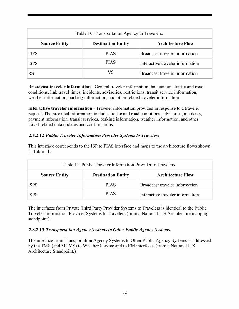
32
Table 10. Transportation Agency to Travelers.
Source Entity Destination Entity Architecture Flow
ISPS PIAS Broadcast traveler information
ISPS PIAS Interactive traveler information
RS VS Broadcast traveler information
Broadcast traveler information - General traveler information that contains traffic and road conditions, link travel times, incidents, advisories, restrictions, transit service information, weather information, parking information, and other related traveler information. Interactive traveler information - Traveler information provided in response to a traveler request. The provided information includes traffic and road conditions, advisories, incidents, payment information, transit services, parking information, weather information, and other travel-related data updates and confirmations.
Public Traveler Information Provider Systems to Travelers 2.8.2.12 This interface corresponds to the ISP to PIAS interface and maps to the architecture flows shown in Table 11:
Table 11. Public Traveler Information Provider to Travelers.
Source Entity Destination Entity Architecture Flow
ISPS PIAS Broadcast traveler information
ISPS PIAS Interactive traveler information
The interfaces from Private Third Party Provider Systems to Travelers is identical to the Public Traveler Information Provider Systems to Travelers (from a National ITS Architecture mapping standpoint).
Transportation Agency Systems to Other Public Agency Systems: 2.8.2.13 The interface from Transportation Agency Systems to Other Public Agency Systems is addressed by the TMS (and MCMS) to Weather Service and to EM interfaces (from a National ITS Architecture Standpoint.)

33
Table 12. Transportation Agency to Other Public Agency.
Source Entity Destination Entity Architecture Flow
Weather Service TMS Road network conditions
TMS EM Incident information
EM TMS Incident information
MCMS Weather Service Road weather information
MCMS Weather Service Environmental conditions data
Other Public Agency to Transportation Agency Systems 2.8.2.14
The interface from Other Public Agency Systems to Transportation Agency Systems is addressed by the Weather Service or EM to TMS or MCMS interfaces (from a National ITS Architecture Standpoint).
Table 13. Other Public Agency to Transportation Agency.
Source Entity Destination Entity Architecture Flow
EM TMS Incident information
Weather Service TMS Qualified environmental conditions data
Weather Service TMS Weather information
Qualified environmental conditions data – Current road conditions (e.g., surface temperature, subsurface temperature, moisture, icing, treatment status) and surface weather conditions (e.g., air temperature, wind speed, precipitation, visibility) that has had quality checks performed on it and has been formatted and consolidated by the Clarus system. Attributes relating to the data collection (and aggregation) are also included. Weather information- Accumulated forecasted and current weather data (e.g., temperature, pressure, wind speed, wind direction, humidity, precipitation, visibility, light conditions, etc.). 2.9 OPERATIONAL SCENARIOS 2.9.1 Introduction to Operational Scenarios Operational scenarios provide the overview of the system processes. They comprise the steps taken as actors accomplish tasks and pass information to another actor. These operational

34
scenarios represent only a subset of the total possible. They also include the rationales and user needs described earlier. While the collection of real time data by transportation or transit agencies and the data distribution to travelers may involve internal interfaces (e.g., collection of speed data from agency owned field devices), these internal interfaces are not the focus of this concept of operations. Rather this concept of operations focuses on the center to center interfaces that are used for the collection and distribution of data. The format that describes the operational scenario is defined as follows: • Operational Scenario Name. Title and identification of the Operational Scenario • Description. A short paragraph that describes the operational scenario and its general flow
of events. • Actors Involved. The actors who participate in the operational scenario. • Initiator (actor). The actor who initiates the scenario is explicitly identified. • Prerequisites. Information that is needed to implement the operational scenario. • Flow of Events. The typical flow of events that occurs as part of the operational scenario. • Alternative Scenarios. These are the exception and special cases that characterize
alternative information or information flows to meet the Operational Scenario. • User Needs. The user needs that are addressed by the Operational Scenario.
Actor Definitions 2.9.1.1 Actors are people or subsystems that interact within the system. In the RTSMIP environment, they are agencies or organizations that are involved in the collection and use of real time information. Actors also represent the external users who may interact with the systems operated by the primary actors, for example, travelers. Table 14 lists the actors, their primary role, and the related stakeholders who apply to the actor category.
Table 14. Actor Definitions and Associated Stakeholders.
Actor Description/Role Stakeholder Examples
Transportation Agencies
Transportation agencies are responsible for managing the road network, either highway or arterials. They collect traffic, incident, and weather data, either with their own field equipment, or by purchasing the data from private data collection organizations). They are also responsible for providing traveler information through roadside devices or through web based means.
State DOT, Municipal DOT or DPW, such as Ohio or Arizona DOT.

35
Table 14. Actor Definitions and Associated Stakeholders.
Actor Description/Role Stakeholder Examples
Transit Agencies
Agencies that operate public transit service operating over the road network. May include busses as well as trains that share right-of-way with roads (light rail).
Regional Bus System such as King County Transit or MTA New York City Transit.
Public Safety Agencies
Agencies that provide public safety answering points (PSAPs) and provide the first response to incidents that occur on the road network.
Police Department, Fire Department, EMS, PSAPs.
Private Data Collection Organizations
Private companies or organizations that collect travel data (e.g., speed data) or road weather data, which they provide to transportation agencies. This also includes companies that collect transit vehicle AVL data and provide it to transit agencies.
Travelers Traveling public- the primary end user of traveler information in its many forms.
Motorists and Transit Passengers.
Public Traveler Information Providers
Public providers of traveler information or other traveler services. These agencies usually do not collect the travel and traffic conditions data themselves, but obtain their data from transportation or transit agencies. They perform data processing to create a regional (or statewide) traveler information view that travelers can access through web based means.
Regional Transportation Agencies such as TRANSCOM in the New York City area or MTC in the San Francisco Bay Area.
Private Third Party Providers
Private companies or organizations that use real time information to create traveler information products such as smart phone applications. This would also include the media, who provide real time traveler information to their listeners/viewers (in the case of radio/television) as part of their overall news and entertainment efforts.
Smartphone Application Developers, radio/TV stations.
Other Public Agencies
Public agencies that do not have a primary transportation role, but still have a need to obtain or provide various real time information.
National Weather Service, National Park Service, US Military

36
2.9.2 Managing the Surface Transportation System Using Real Time Information
Table 15. Operational Scenario – Using Real Time Information.
Operational Scenario Element
Description
Operational Scenario Name:
Managing the surface transportation system using real time information.
Description: Using real time information such as vehicle speeds, incident information, lane closures, and road weather information to manage and operate the transportation network.
Actors Involved: Transportation agencies, Private Data Collections Organizations, Public Safety Agencies.
Initiator (actor): Transportation agencies.
Prerequisites: Availability of information about the road network.

37
Table 15. Operational Scenario – Using Real Time Information.
Operational Scenario Element
Description
Flow of Events: 1. The transportation agency collects real time information from the following sources: • Link speed data from peer transportation agencies. • Incident information from (or combined from) one or more public
safety agencies (e.g., local PSAP 9-1-1 call-taker agencies) or from peer transportation agencies.
• Lane or road closure information from peer transportation agencies 2. Road weather data from peer transportation agencies. 3. The transportation agency collects real time information from the
following sources: • Link speed data from peer transportation agencies. • Incident information from (or combined from) one or more public
safety agencies (e.g., local PSAP 9-1-1 call-taker agencies) or from peer transportation agencies.
• Lane or road closure information from peer transportation agencies. • Road weather data from peer transportation agencies.
4. The transportation agency uses the real time information to manage highway traffic flow through adjustment of: • Ramp meter timing. • Variable speed limits. • Lane control devices. (Note that communication with the traveling public is illustrated in the Section 2.9.4 scenario.)

38
Table 15. Operational Scenario – Using Real Time Information.
Operational Scenario Element
Description
Alternative scenarios:
Alternative 1: Data Collection from private data collection organizations or other public agencies. As an alternate data collection method, transportation agencies may get real time information for speed or road weather conditions from Private Data Collection Organizations instead of the transportation agency equipment. The Private Data Collection Organization aggregates data collected and provides it to the transportation agency. Road weather data may also be obtained from other public agencies such as the National Weather Service. In many cases agencies may use both this alternative and the basic scenario. Alternative 2: Managing arterial networks using real time data. In an alternative to step 2 above, arterial traffic flow can also be managed by adjusting the timing of the traffic signal control systems. Alternative 3: Data provided from Transportation Agency internal sources. An alternative data collection scenario (that involves internal agency interfaces only) is to collect the following data from agency owned field devices- link speed data, incident information and road weather sensor data. A second internal interface for data is data on road or lane closure due to construction which is obtained from transportation agency construction staff (usually through an agency internal interface or system).
User Needs: 2.5.2.1 Speed Data for Roads. 2.5.3.1 Incident Information from Public Safety for Network Management. 2.5.3.4 Incident Information from Peer Transportation Agencies. 2.5.4.2 Construction Information for Road Management.

39
2.9.3 Maintaining the Surface Transportation System Using Real Time Road Weather Information
Table 16. Operational Scenario - Using Real Time Weather Information
Operational Scenario Element
Description
Operational Scenario Name:
Maintaining the surface transportation system using real time road weather information
Description: Transportation agencies use road weather information to support maintenance of the roadway network.
Actors Involved: Transportation agencies, Private Data Collections Organizations, and Other Public Agencies.
Initiator (actor): Transportation agencies
Prerequisites: Availability of road weather data for the road network
Flow of Events: 1. The transportation agency collects real time weather data/ information from the following sources: • Peer Transportation Agencies. • Private Data Collection Organizations. • Other Public Agencies (e.g., NWS). The data received may be raw sensor data or aggregated data collected and provided to the transportation agency.
2. The weather information is used to direct maintenance crews to respond
to a weather event, either proactively or retroactively. • Maintenance vehicles can be dispatched to deposit surface treatments
on roadways ahead of a snow or ice storm. • Maintenance vehicles can be dispatched to plow and deposit surface
treatments on roadways after a snow or ice storm.
Alternative scenarios:
Alternative 1: Data Collection using Transportation Agency Devices. An alternative data collection scenario (that involves internal agency interfaces only) is to collect road weather sensor data from agency owned field devices. In most cases agencies may use both this alternative and the basic scenario for data collection.
User Needs: 2.5.5. Road Weather Environmental Conditions Data for Maintenance Operations. 2.5.5.3 Receive Forecasts of Upcoming Adverse Weather Related Conditions.

40
2.9.4 Share Information with the Traveling Public
Table 17. Operational Scenario – Sharing Information with Traveling Public.
Operational Scenario Element
Description
Operational Scenario Name:
Share information with the traveling public
Description: Dissemination of information such as vehicle speeds, incident information, lane closures to the general public
Actors Involved:
Transportation Agencies, Transit Agencies, Private Data Collection Organizations, Travelers, Public Traveler Information Providers, Public Safety Agencies
Initiator (actor):
Transportation Agencies
Prerequisites: Availability of information about the road network.
Flow of Events:
1. The transportation agency collects real time information from the following sources: • Link speed or travel time data from peer transportation agencies • Incident information from one or more public safety agencies (e.g.,
local PSAP 9-1-1 call-taker agencies) or from peer transportation agencies.
• Lane or road closure information from peer transportation agencies. • Road weather data from peer transportation agencies or Other Public
Agencies.
2. The transportation agency compiles information for travelers: • Travel time and delays • Location of incidents and extent of traffic impacts • Road or lane closures and detours • Severe weather information
3. Information is delivered to travelers via roadside devices: • DMS - Display information to motorists • HAR - Read information to motorists • Connected Vehicle Roadside Units

41
Table 17. Operational Scenario – Sharing Information with Traveling Public.
Operational Scenario Element
Description
Flow of Events: (continued)
4. Information is updated as additional real time data becomes available 5. As incidents are resolved and delays clear, alerts are removed.
Alternative scenarios:
Alternative 1: Transit Information for Travelers. An alternative scenario is providing transit information to travelers. 1. In this scenario the transit agency collects real time vehicle location
information from AVL systems. 2. Information is prepared to be disseminated to travelers:
• Delay and service change information. • Next arrival/departure at a given stop. • Travel time information.
3. Information is delivered to travelers: • Transit agency website or smartphone applications. • DMS at transit stops. • Telephone information system.
Alternative 2: Traveler Information Service. In this alternative scenario, information is disseminated to travelers via a traveler information service (often known as 5-1-1). Information can be obtained in several ways:
• Visiting a website or using a smartphone application to obtain real time travel information in either a map or list format.
• Calling 5-1-1 from a mobile or landline phone and using a series of voice or touch-tone keypad prompts to obtain audible travel information.
Alternative 3: Public Traveler Information Provider. Roadway and transit information may be disseminated to travelers via a Traveler Information Provider instead of a Transportation or Transit Agency. The flow of events is the same.

42
Table 17. Operational Scenario – Sharing Information with Traveling Public.
Operational Scenario Element
Description
User Needs: 2.5.2.2 Travel Time Data for Roads. 2.5.2.3 Speed Data for Public Traveler Information Providers. 2.5.2.6 Transit Vehicle Travel Time. 2.5.3.2 Incident Information from Public Safety for Traveler Information. 2.5.3.8 Planned Event Information for Traveler Information. 2.5.4.1 Construction Information for Traveler Information. 2.5.5.1 Road Weather Environmental Conditions Data to support Traveler Information. 2.5.5.3 Receive Forecasts of Upcoming Adverse Weather Related Conditions. 2.5.6.1 Real Time Bus Locations. 2.5.6.2 Real Time Transit Passenger Loading. 2.5.6.3 Predicted Bus of Train Arrival/Departure Times.
2.9.5 Share Information with State and Local Government Agencies
Table 18. Operational Scenario – Sharing Information with State and Local Government Agencies
Operational Scenario Element
Description
Operational Scenario Name:
Share information with state and local government agencies.
Description: Sharing real time information with peer transportation agencies and public safety agencies.
Actors Involved:
Transportation Agencies, Public Safety Agencies, Transit Agencies.
Initiator (actor):
Transportation Agencies.
Prerequisites: Availability of real time information for the road network, data sharing agreements.

43
Table 18. Operational Scenario – Sharing Information with State and Local Government Agencies
Operational Scenario Element
Description
Flow of Events:
1. The transportation agency collects real time information from the following sources: • Link speed data from agency owned field devices, private data
collection organizations, and/or from peer transportation agencies • Incident information from Public Safety agencies or from agency owned
CCTV. • Lane or road closure information from peer transportation agencies or
from transportation agency construction staff. • Road weather data from private data collection organizations, other
public agencies, peer transportation agencies, or from agency owned sensor.
2. The transportation agency sends collected data in real time to peer transportation agencies that have data sharing agreements. The agency also sends data about planned events and construction.
3. The peer transportation agency uses this data to manage its network of limited access and arterial roadways as a result of conditions in the jurisdiction of the agency submitting data.

44
Table 18. Operational Scenario – Sharing Information with State and Local Government Agencies
Operational Scenario Element
Description
Alternative scenarios:
Alternative 1: Sharing Real Time Information with Public Safety Agencies In event 2, real time transportation information is shared with public safety agencies that have a real time information sharing agreement. The agency also sends information about planned events and construction. In event 3, the information from the transportation agency is used by public safety agencies to dispatch first responders to the scene of an incident. It is also used to assist first responders in using the most efficient route to reach the scene of an incident and to manage the incident on scene. Alternative 2: Sharing Real Time Information with Transit Agencies In event 2, real time transportation information is shared with transit agencies that have a real time information sharing agreement. The agency also sends information about planned events and construction. Sharing can be from transportation agency or from public traveler information provider. In event 3, the information is used by the transit agency to adjust transit service as a result of current conditions.
User Needs: 2.5.3.3 Incident Information from Transportation Agencies for Public Safety 2.5.3.5 Incident Information for Transit Agencies 2.5.3.9 Planned Event Information for Peer Transportation Agencies and Other Parties 2.5.4.3 Construction Information for Peer Transportation Agencies and Other Parties 2.5.5.5 Road Weather Information for Peer Transportation Agencies and Other Parties

45
2.9.6 Share Information with Public Traveler Information Providers
Table 19. Operational Scenario – Sharing Information with Public Traveler Information Providers.
Operational Scenario Element
Description
Operational Scenario Name:
Share information with public traveler information providers
Description: Sharing real time information with regional public traveler information providers
Actors Involved:
Transportation Agencies, Public Traveler Information Providers
Initiator (actor):
Transportation Agencies
Prerequisites: Availability of real time information for the road network, information sharing agreements.
Flow of Events:
1. The transportation agency collects real time data from the following sources: • Link speed data from agency owned field devices and/or from peer
transportation agencies • Incident information from Public safety agencies or from agency owned
CCTV. • Lane or road closure information from transportation agency
construction staff • Road weather data from agency owned sensors, private data collection
organizations , or other public agencies
2. The transportation agency sends collected information in real time to a public traveler information provider that it has an information sharing agreement with. The agency also sends information about planned events and construction.
3. The traveler information agency or public traveler information provider redistributes real time information and planned event and construction information to transportation agencies that it has agreements with. It will also output the information to the public.

46
Table 19. Operational Scenario – Sharing Information with Public Traveler Information Providers.
Operational Scenario Element
Description
Alternative scenarios:
None.
User Needs: 2.5.2.3 Speed Data for Public Traveler Information Providers 2.5.2.4 Travel Time Data for Public Traveler Information Providers 2.5.3.6 Incident Information for Public Traveler Information Providers 2.5.3.8 Planned Event Information for Traveler Information 2.5.3.9 Planned Event Information for Peer Transportation Agencies and Other Parties 2.5.4.3 Construction Information for Peer Transportation Agencies and Other Parties 2.5.5.3 Receive Forecasts of Upcoming Adverse Weather Related Conditions 2.5.5.5 Road Weather Information for Peer Transportation Agencies and Other Parties
2.9.7 Share Information with Private Third Party Providers
Table 20. Sharing Information with Private Third Party Providers.
Operational Scenario Element
Description
Operational Scenario Name:
Share information with private third party providers
Description: Sharing real time information with private third party providers who create applications to inform the traveling public of current conditions
Actors Involved:
Transportation Agencies, Transit Agencies, Traveler Information Providers, Private Third Party Providers
Initiator (actor):
Transportation Agencies, Public Traveler Information Providers
Prerequisites: Availability of real time information for the road network, information sharing agreements.

47
Table 20. Sharing Information with Private Third Party Providers.
Operational Scenario Element
Description
Flow of Events:
1. The transportation agency collects real time information from the following sources: • Link speed data from agency owned field devices or from peer
transportation agencies • Incident information from Public safety agencies or from agency owned
CCTV. • Lane or road closure information from transportation agency
construction staff • Road weather data from agency owned sensors
2. The transportation agency aggregates transportation real time information
that is suitable to be released to the public. This may include speed and travel time information, incident information, construction information, and weather forecasts and conditions information. Additionally, information about planned events and planned construction may be included.
3. The transportation agency provider distributes a data feed of real time information and planned event and construction information to third party providers.
4. The private third party provider disseminates relevant information to the
traveling public via a web, mobile application, or other media. The application may have a very limited scope (e.g., just providing construction information), or may be very broad in scope (e.g., providing total situational awareness of regional traffic conditions).
Alternative scenarios:
Alternative 1: Information from Traveler information Providers Information to private third party providers is provided by public traveler information provider instead of transportation agencies. Alternative 2: Information from Transit Agencies Information to private third party providers is provided by transit agencies instead of transportation agencies. In the case of event 1, the transit agency collects transit vehicle information to support distribution of information. In event 2, the transit agency aggregates the raw data to create data streams that can be provided to other agencies. Events 3 and 4 unfold as described above.

48
Table 20. Sharing Information with Private Third Party Providers.
Operational Scenario Element
Description
User Needs: 2.5.2.5 Travel Time Data for Parties who Create Value added Information Products 2.5.2.6 Transit Vehicle Travel Time 2.5.3.7 Incident Information for Parties who Create Value Added Information Products 2.5.4.3 Construction Information for Peer Transportation Agencies and Other Parties 2.5.5.4 Provide Forecasts of Upcoming Adverse Weather Related Conditions 2.5.5.5 Road Weather Information for Peer Transportation Agencies and Other Parties 2.5.6.1 Real Time Bus Locations 2.5.6.3 Real Time Bus or Train Arrival/Departure Times

49
FUNCTIONAL REQUIREMENTS 3. This section defines the Functional Requirements based on the user needs identified in the Concept of Operations (see Section 2). This section includes: • A tutorial which describes the type of requirements contained in this document and gives
some indication of how requirements are written. • Scope of the Interface – Describes the nature of the interfaces covered by this document. • The Needs to Requirements Traceability Matrix – A Functional Requirement is a requirement
to satisfy a given feature and therefore is only required to be implemented if the associated feature (e.g., user need) is selected through the use of the Needs to Requirements Traceability Matrix (NRTM). The NRTM also indicates which of the items are mandatory, conditional, or optional. The NRTM can be used by procurement personnel to specify the desired features of a connected device or can be used by a manufacturer to document the features supported by their implementation. Due to the size of the NRTM it is contained in a separate Annex A.
• Architectural Requirements – This section defines basic modes of operation. • Data Exchange Requirements – These are requirements related to the features identified in
Section 2.5 that can be realized through a data exchange. For example, this includes the requirement to be able to transmit a vehicle’s position and speed.
• Performance Requirements – These are some basic performance requirements derived from TMDD.
3.1 TUTORIAL This systems requirements specification (SRS) defines the formal requirements that are intended to satisfy the user needs identified in Section 2.5 of this document. This is achieved through the development of a NRTM that traces each user need to one or more requirements defined in this section. The details of each requirement are then presented following the NRTM. The functional requirements are presented in three broad categories as follows: • Architectural Requirements – These requirements define the required behavior of the system
in exchanging data across the communications interface, including any restrictions to general architectural requirements, based upon the architectural needs identified in this document.
• Data Exchange and Operational Environmental Requirements – These requirements define the required behavior of the system in exchanging data across the communications interface based upon the features identified in this document.
The SRS is a specification for a particular product that performs certain functions in a specific environment. The purpose of this SRS is to document the full set of functions to meet the user needs defined in this DXFS. This SRS will address the functionality needed to meet the user needs of the RTSMIP as defined by this DXFS. The following criteria are used when documenting and writing requirements:

50
1. Is it a well-formed requirement? Some of the attributes of well-formed requirements are:
a. Necessary – Is the requirement an essential part of the system? b. Clear – Can the requirement be interpreted one and only one way? c. Complete – Can the requirement stand on its own without further clarification? d. Consistent – Does the requirement contradict or duplicate another requirement? e. Achievable – Is the requirement technically feasible at a reasonable cost and in a
reasonable time? f. Verifiable – Can one unambiguously determine if the requirement has been met? g. Concise – Is the requirement described succinctly and without superfluous text? h. Technology independent – Is the requirement statement technology independent?
2. Is the requirement mapped to one or more user needs? This will also address whether the
requirement is in fact needed.
3. Does the requirement, with its sibling requirements, satisfy the intent and all key items of the need?
The well-formed requirements will generally take the form: [Actor] [Action] [Target] [Constraint] [Localization]. The localization and constraint portions are important, but not all requirements will have both. The constraint identifies how you will measure success or failure of the requirement. The localization identifies the circumstances under which the requirement applies. For example: The System [Actor] shall generate [Action] event reports [Target] containing the following information [Constraint] on a scheduled interval [localization]. 3.2 SCOPE OF THE REQUIREMENTS The DXFS addresses information that is sent from an owning center to another external center. There are several stakeholders that can represent either owning center or external center, but fundamentally all the information sharing is between these two types of centers. This same situation applies to the Traffic Management Data Dictionary (TMDD) standard as well. This standard is the only ITS center to center standard that contains a set of requirements, and many of these requirements apply to RTSMIP. Where requirements from TMDD Vol 1 satisfy RTSMIP needs defined in this DXFS (e.g., providing link or route travel times), the DXFS does not reproduce the requirement, but contains a reference to the requirement name and paragraph number in the TMDD. Because some but not all of the TMDD requirements are used here, the paragraph numbering of the DXFS (in Section 3) does not match that found in the TMDD standard. 3.3 NEEDS TO REQUIREMENTS TRACEABILITY MATRIX (NRTM) The Needs to Requirements Traceability Matrix (NRTM) discussed in Section 3.3.3 (and contained in Annex A), maps the user needs defined in Section 2.5 to the requirements defined in Section 3.5-3.6 of this document. The table lists each user need to be addressed by the DXFS,

51
followed immediately by the requirement(s) that supports (and traces to) that user need. The table can be used by: • A user or specification writer to indicate which requirements are to be implemented in a
project-specific implementation. • The interface implementer, as a checklist to reduce the risk of failure to conform to the
standard through oversight. • The supplier and user, as a detailed indication of the capabilities of the implementation. • The user, as a basis for initially checking the potential interoperability with another
implementation. Annex A – Needs to Requirements Traceability Matrix (NRTM), contained in a separate volume, includes a Needs to Requirements Traceability Matrix (Table A-1) followed by a smaller table (Table A-2) which maps user needs to requirements in Section 3.4 Architecture Requirements. 3.3.1 Notation The following notations and symbols are used to indicate status and conditional status in the NRTM within this standard. Not all of these notations and symbols are necessarily used within this standard.
Conformance Symbols 3.3.1.1 The following symbols are used to indicate status in the NRTM table (Section 3.3.3):
Table 21. Conformance Symbols.
Symbol Value
M Mandatory – This requirement(s) is required to support the specified user need.
M.# Support of every item of the group labeled by the same numeral # is required, but only one is active at a time
O Optional - This requirement may be included in support of the specified user need
O.# (range) Part of an option group. Support of the number of items indicated by the ‘(range)’ is required from all options labeled with the same numeral #
N/A Not-applicable (i.e. logically impossible in the scope of the standard)
The O.# (range) notation is used to show a set of selectable options (e.g., O.2 (1..*)) would indicate that one or more of the option group 2 options must be implemented. Much of the NRTM is based upon the NTRM from TMDD Volume 1 (meaning that the conformance indication for requirements equals that given in TMDD). In some cases the entry in the NRTM is different due to the specific user need. For example user need 2.5.2.1 Speed Data

52
for Limited Access Roads will have requirement 3.5.3.3.2.5.2.5 Link Average Speed as M, in this DXFS while in TMDD this requirement is O. Where the conformance requirement differs from TMDD the entry in the NRTM will indicated with a “*”.
Conditional Status Notation 3.3.1.2 The following predicate notation may be used:
Table 22. Predicate Notations.
Symbol Value
<predicate>: This notation introduces a single item that is conditional on the <predicate>.
<predicate>:: This notation introduces a table or a group of tables, all of which are conditional on the <predicate>.
(predicate) This notation introduces the first occurrence of the predicate either in the NRTM or in that specific user need. The feature associated with this notation is the base feature for all options that have this predicate in their conformance column.
The <predicate>: notation means that the status following it applies only when the NRTM states that the feature or features identified by the predicate are supported. In the simplest case, <predicate> is the identifying tag of a single NRTM item. When the group predicate is true then the associated section shall be completed. The symbol <predicate> also may be a Boolean expression composed of several indices. .AND., .OR., and .NOT. shall be used to indicate the Boolean logical operations. The predicates used in the NRTM map to the following sections.
Table 23. Predicates.
Predicate Section
AreaLocation 3.5.2.6.4.7.1
Detour 3.5.2.6.4.6.2
EventComments 3.5.2.7.4
EventDescription 3.5.2.6.4.6
EventHazMat 3.5.2.6.5.1
EventIndicator 3.5.2.7.2
EventLane 3.5.2.6.4.9
EventLocation 3.5.2.6.4.7

53
Table 23. Predicates.
Predicate Section
EventPeriod 3.5.2.6.4.1.2.1
EventReferences 3.5.2.7.3
EventReports 3.5.2.7.5
EventTime 3.5.2.6.4.1
HazMatCode 3.5.2.6.5.1.1
HazMatPlacard 3.5.2.6.5.1.2
Landmark 3.5.2.6.4.7.6
LinkLocation 3.5.2.6.4.7.2
PointOnALink 3.5.2.6.4.7.4
ProjectReference 3.5.2.7.1
SiteMetadata 3.5.4.2.4.3.7
StationMetadata 3.5.4.2.4.3.8
Subscription 3.4.2
3.3.2 Needs to Requirements Traceability Matrix (NRTM) Table In addition to the conformance column and the support column, which were discussed in Section 3.3.1, the additional columns in the NRTM table are the User Need ID and User Need columns, FR ID and Functional Requirement columns.
User Need ID and User Needs Column 3.3.2.1 The user needs are defined within the Section 2.5 of this document and the NRTM is based upon the user need within that Section. The section number and user need name are indicated within these columns.
FR ID Requirements Type and Requirements Columns 3.3.2.2 The requirements are defined within Sections 3.4 to 3.6 and the NRTM references the traces from user needs to these requirements. The requirement type, section number and requirements name are indicated within these columns.

54
Using the NRTM to define a system 3.3.2.3 This document is an informational level specification used to define information exchanges between a center and other centers. In order to use the specification to define a system the developer should first select the user needs that will be addressed by the system. For each user need, the NRTM identifies the set of requirements that relate to that user need. All Mandatory requirements must be selected in order to satisfy the user need. Depending on the deployment some (or all, or none) of the optional requirements will be selected. The requirements identified in the NRTM are mapped in Section 4 of this document to data concepts (dialogs, messages, data frames, or data elements) of other ITS standards (e.g., Traffic Management Data Dictionary). In order to facilitate the selection of the optional requirements, all the requirements under each user need in the NRTM have been organized to indicate what type of data concept will be implemented to satisfy the requirement. This mapping can be categorized as one of four types of data concept: • Dialog – a requirement to describe the sequence or conditions for information exchanges
between a center and other centers. • Request Message – the requirement used to describe the message sent from an external center
to an owner center. • Response Message – a requirement to describe the message sent from an owner center to an
external center. • Error Message – a requirement to describe the error report message. Note that many requirements are mapped in Section 4 to data concepts that form a part of a message (e.g., data frames or data elements), but these lower level data concepts are never exchanged by themselves, but always as a part of a message. Hence the characterization of requirements into the four categories shown above. A more detailed discussion of how to use the DXFS to define a system is provided in the DXFS Implementation Guidance Document. 3.4 ARCHITECTURAL REQUIREMENTS The requirements to manage the interface connections between centers are as follows: 3.4.1 Connection Management The requirements to manage the interface connections between centers are as follows:
Exchange Center Active Verification 3.4.1.1 Each center that is part of the C2C network supports the exchange of center active information with the following requirements. 3.4.1.1.1 Send Center Active Verification Upon Request The requirement for Send Center Active Verification Upon Request is defined by Section 3.3.1.1.1 of the TMDD standard.

55
3.4.1.1.2 Publish Center Active Verification Information The requirement for Publish Center Active Verification Information is defined by Section 3.3.1.1.2 of the TMDD standard. 3.4.1.1.3 Subscribe to Center Active Verification Information The requirement for Subscribe to Center Active Verification Information is defined by Section 3.3.1.1.3 of the TMDD standard. 3.4.1.1.4 Contents of the Center Active Verification Request The requirement for Contents of the Center Active Verification Request is defined by Section 3.3.1.1.4 of the TMDD standard. 3.4.1.1.5 Required Center Active Verification Request Content The requirement for Required Center Active Verification Request Content is defined by Section 3.3.1.1.4.1 of the TMDD standard. 3.4.1.1.6 Contents of the Center Active Information The requirement for Contents of the Center Active Information is defined by Section 3.3.1.1.5 of the TMDD standard. 3.4.1.1.7 Required Center Active Information The requirement for Required Center Active Information is defined by Section 3.3.1.1.5.1 of the TMDD standard. 3.4.1.1.8 Optional Center Active Information The following are optional requirements that an owner center may include in the center active information sent to an external center. 3.4.1.1.9 Restrictions – Center Active The requirement for Restrictions – Center Active is defined by Section 3.3.1.1.5.2.1 of the TMDD standard. 3.4.2 Support Request-Response The requirement for Support Request-Response is defined by Section 3.3.1.2 of the TMDD standard.

56
3.4.3 Support Subscription-Publication The requirements to support subscription-publication of messages between centers are as follows:
Support Periodic Updates 3.4.3.1 The requirement for Support Periodic Updates is defined by Section 3.3.1.3.1 of the TMDD standard.
Support Event-Driven Updates 3.4.3.2 The requirement for Support Event-Driven Updates is defined by Section 3.3.1.3.2 of the TMDD standard. 3.4.4 Support Error Handling Report The following are requirements for reporting errors encountered during the exchange of information between centers.
Contents of the Error Report 3.4.4.1 The requirement for Contents of the Error Report is defined by Section 3.3.1.4.1 of the TMDD standard. 3.4.4.1.1 Required Error Report Contents The requirement for Required Error Report Contents is defined by Section 3.3.1.4.1.1 of the TMDD standard. 3.4.4.1.2 Optional Error Report Contents The following are optional requirements that an owner center may include in the error report information sent to an external center. 3.4.4.1.3 Restrictions - Error Report: The requirement for Restrictions - Error Report is
defined by Section 3.3.1.4.1.2.1 of the TMDD standard.
3.5 FUNCTIONAL REQUIREMENTS 3.5.1 Provide Information on Organizations and Centers This section covers the relevant requirements for the information regarding organizations that will be sent as part of the real time network, event and device information that addresses the RTSMIP user needs. A more complete set of organizational data that could form part of information exchange between centers in contexts beyond those defined by the DXFS is contained in TMDD Section 3.3.2.

57
Contents of the Organization and Centers Information 3.5.1.1
The requirement for Contents of the Organization and Centers Information is defined by Section 3.3.2.5 of the TMDD standard. 3.5.1.1.1 Required Organization Information Content The requirement for Required Organization and Information Content is defined by Section 3.3.2.5.1 of the TMDD standard. 3.5.2 Events Information Sharing The key needs of RTSMIP described in this DXFS for the sharing of incident information and construction related road or lane closures is addressed by the TMDD requirements for Events Information Sharing. The following set of requirements represents a subset of the complete event information requirements that are relevant to RTSMIP.
Send Event Information Upon Request 3.5.2.1 The requirement for Send Event Information Upon Request is defined by Section 3.3.3.1 of the TMDD standard.
Publish Event Information 3.5.2.2 The requirement for Publish Event Information is defined by Section 3.3.3.2 of the TMDD standard.
Subscribe to Event Information 3.5.2.3 The requirement for Subscribe to Event Information is defined by Section 3.3.3.3 of the TMDD standard.
Contents of Event Information Request 3.5.2.4 The requirement for Contents of Event Information Request is defined by Section 3.3.3.4 of the TMDD standard. 3.5.2.4.1 Required Event Information Request Content The requirements for Required Event Information Request Content are defined by Section 3.3.3.4.1 of the TMDD standard.
58
3.5.2.4.2 Optional Event Message Header Information The following are optional requirements that an external center may include in the event information request sent to an external center. 3.5.2.4.2.1 Authentication – Events The requirement for Authentication - Events is defined by Section 3.3.3.4.2.1 of the TMDD standard. 3.5.2.4.2.2 Operator Identifier – Events The requirement for Operator Identifier - Events is defined by Section 3.3.3.4.2.1.1 of the TMDD standard. 3.5.2.4.2.3 Requesting Organization – Events The requirement for Requesting Organization - Events is defined by Section 3.3.3.4.2.2 of the TMDD standard. 3.5.2.4.3 Event Information Request Filter Content Centers may be tracking multiple events at any one time, with each event containing lengthy pieces of information. Centers may wish to search for only those events that meet specific criteria, such as a specific type of event, events at a specific location or a recap of current events that had been updated since a specified date and time. If the owner center supports filtering of event information, the following are optional filtering requirements that an external center may include in the event information request sent to the owner center. Multiple filters may be sent. 3.5.2.4.3.1 Event Unique Identifier Filter The requirement for Event Unique Identifier Filter is defined by Section 3.3.3.4.3.1 of the TMDD standard. 3.5.2.4.3.2 Event Response Plan Identifier Filter The requirement for Event Response Plan Identifier Filter is defined by Section 3.3.3.4.3.2 of the TMDD standard. 3.5.2.4.3.3 Event Category Filter The requirement for Event Category Filter is defined by Section 3.3.3.4.3.3 of the TMDD standard.

59
3.5.2.4.3.4 Event Priority Filter The requirement for Event Priority Filter is defined by Section 3.3.3.4.3.4 of the TMDD standard. 3.5.2.4.3.5 Event Description Confidence Level Filter The requirement for Event Description Confidence Level Filter is defined by Section 3.3.3.4.3.5 of the TMDD standard. 3.5.2.4.3.6 Event Access Level Filter The requirement for Event Access Level Filter is defined by Section 3.3.3.4.3.6 of the TMDD standard. 3.5.2.4.3.7 Event Action Flag Filter The requirement for Event Action Flag Filter is defined by Section 3.3.3.4.3.7 of the TMDD standard. 3.5.2.4.3.8 Event Severity Filter The requirement for Event Severity Filter is defined by Section 3.3.3.4.3.8 of the TMDD standard. 3.5.2.4.3.9 External Center Organization Filter The requirement for External Center Organization Filter is defined by Section 3.3.3.4.3.9 of the TMDD standard. 3.5.2.4.3.10 Event Location Filter The requirements for Event Location Filter are defined by Section 3.3.3.4.3.10 of the TMDD standard. 3.5.2.4.3.11 Request Start Time Filter The requirement for Request Start Time Filter is defined by Section 3.3.3.4.3.11 of the TMDD standard. 3.5.2.4.3.12 Request End Time Filter The requirement for Request End Time Filter is defined by Section 3.3.3.4.3.12 of the TMDD standard.

60
3.5.2.4.3.13 Hazardous Material Codes Filter The requirement for Hazardous Material Codes Filter is defined by Section 3.3.3.4.3.13 of the TMDD standard. 3.5.2.4.3.14 Hazardous Material Placard Codes Filter The requirement for Hazardous Material Placard Codes Filter is defined by Section 3.3.3.4.3.14 of the TMDD standard. 3.5.2.4.3.15 Event Headline Filter The requirement for Event Headline Filter is defined by Section 3.3.3.4.3.15 of the TMDD standard.
Contents of the Event Information: 3.5.2.5 The requirement for Contents of the Event Information is defined by Section 3.3.3.5 of the TMDD standard.
Required Event Information Content 3.5.2.6 The requirements for Required Event Information Content are defined by Section 3.3.3.6 of the TMDD standard. The requirements for each aspect of the event information are given below. 3.5.2.6.1 Event Message Header The following are requirements for the contents of the event message header information sent from an owner center to an external center. 3.5.2.6.2 Required Event Message Header Information The requirements for Required Event Message Header Information are defined by Section 3.3.3.6.1.1 of the TMDD standard. 3.5.2.6.3 Optional Event Message Header Information The following are optional requirements that an owner center may include in the event message header information sent to an external center. 3.5.2.6.3.1 External Center Organization - Events The requirement for External Center Organization - Events is defined by Section 3.3.3.6.1.2.1 of the TMDD standard.

61
3.5.2.6.3.2 Responding Organization The requirement for Responding Organization is defined by Section 3.3.3.6.1.2.2 of the TMDD standard. 3.5.2.6.3.3 Message Expiry Time The requirement for Message Expiry Time is defined by Section 3.3.3.6.1.2.3 of the TMDD standard. 3.5.2.6.4 Event Reference The following are requirements for the contents of the event reference information sent to an external center. 3.5.2.6.4.1 Required Event Reference Information The requirement for Required Event Reference Information is defined by Section 3.3.3.6.2.1 of the TMDD standard. 3.5.2.6.4.2 Optional Event Reference Information The following are optional requirements that an owner center may include in the event reference information sent to an external center. 3.5.2.6.4.3 Event Response Plan Identifier The requirement for Event Response Plan Identifier is defined by Section 3.3.3.6.2.2.1 of the TMDD standard. 3.5.2.6.4.4 Event Headline The following are requirements for the contents of the event headline information sent from an owner center to an external center. There may be multiple instances of event headline information. Note: The event headline information is optional IF and ONLY IF the event information message is used to close an open event. 3.5.2.6.4.5 Required Event Headline Information The requirement for Required Event Headline Information is defined by Section 3.3.3.6.3.1 of the TMDD standard.

62
3.5.2.6.4.6 Optional Event Headline Information The following are optional requirements that an owner center may include in the event headline information sent to an external center. 3.5.2.6.4.6.1 Event Headline Element The requirement for Event Headline Element is defined by Section 3.3.3.6.3.2.1 of the TMDD standard. 3.5.2.6.5 Event Element Details The following are requirements for the contents of the event element details information sent to an external center. There may be multiple instances for the event element details information. Note: The event element details information is optional IF and ONLY IF the event information message is sent to close an open event. 3.5.2.6.5.1 Event Time The requirement for Event Time is defined by Section 3.3.3.6.4.1 of the TMDD standard. 3.5.2.6.5.1.1 Required Event Time Information The requirement for Required Event Time Information is defined by Section 3.3.3.6.4.1.1 of the TMDD standard. 3.5.2.6.5.1.2 Optional Event Time Information The following are optional requirements that an owner center may include in the event time information sent to an external center. 3.5.2.6.5.1.2.1 Event Valid Period The requirement for Event Valid Period is defined by Section 3.3.3.6.4.1.2.1 of the TMDD standard. 3.5.2.6.5.1.2.1.1 Required Event Effective Period Information The requirement for Required Event Effective Period Information is defined by Section 3.3.3.6.4.1.2.1.1 of the TMDD standard.

63
3.5.2.6.5.1.2.1.2 Optional Effective Period Information If the event valid period is defined by an effective period, then the following are optional requirements that an owner center may include in the event valid period sent to an external center. 3.5.2.6.5.1.2.1.3 Effective Period Qualifier The requirement for Effective Period Qualifier is defined by Section 3.3.3.6.4.1.2.1.2.1 of the TMDD standard. 3.5.2.6.5.1.2.1.4 Days Event Not In Effect The requirement for Days Event Not In Effect is defined by Section 3.3.3.6.4.1.2.1.2.2 of the TMDD standard. 3.5.2.6.5.1.2.2 Planned Event Schedule Element Identifier The requirement for Planned Event Schedule Element Identifier is defined by Section 3.3.3.6.4.1.2.2 of the TMDD standard. 3.5.2.6.5.1.2.3 Sequence Date/Time The requirement for Sequence Date/Time is defined by Section 3.3.3.6.4.1.2.3 of the TMDD standard. 3.5.2.6.5.1.2.4 Event Start Date/Time The requirement for Event Start Date/Time is defined by Section 3.3.3.6.4.1.2.4 of the TMDD standard. 3.5.2.6.5.1.2.5 Alternate Start Date/Time The requirement for Alternate Start Date/Time is defined by Section 3.3.3.6.4.1.2.5 of the TMDD standard. 3.5.2.6.5.1.2.6 Alternate End Date/Time The requirement for Alternate End Date/Time is defined by Section 3.3.3.6.4.1.2.6 of the TMDD standard. 3.5.2.6.5.1.2.7 Expected Start Date/Time The requirement for Expected Start Date/Time is defined by Section 3.3.3.6.4.1.2.7 of the TMDD standard.

64
3.5.2.6.5.1.2.8 Expected End Date/Time The requirement for Expected End Date/Time is defined by Section 3.3.3.6.4.1.2.8 of the TMDD standard. 3.5.2.6.5.1.2.9 Recurrent Times Event in Effect The requirement for Recurrent Times Event in Effect is defined by Section 3.3.3.6.4.1.2.9 of the TMDD standard. 3.5.2.6.5.1.2.10 Planned Event Continuous Flag The requirement for Planned Event Continuous Flag is defined by Section 3.3.3.6.4.1.2.10 of the TMDD standard. 3.5.2.6.5.2 Element Identifier The requirement for Element Identifier is defined by Section 3.3.3.6.4.2 of the TMDD standard. 3.5.2.6.5.3 Schedule Element Identifier The requirement for Schedule Element Identifier is defined by Section 3.3.3.6.4.3 of the TMDD standard. 3.5.2.6.5.4 Event Category The requirement for Event Category is defined by Section 3.3.3.6.4.4 of the TMDD standard. 3.5.2.6.5.5 Event Source If the owner center supports event source, the elements details information sent from an owner center to an external center may include the event source information as described in the following. 3.5.2.6.5.5.1 Information Source Organization
The requirement for Information Source Organization is defined by Section 3.3.3.6.4.5.1 of the TMDD standard.
3.5.2.6.5.5.2 Event Detection Method The requirement for Event Detection Method is defined by Section 3.3.3.6.4.5.2 of the TMDD standard. 3.5.2.6.5.6 Event Description The requirement for Event Description is defined by Section 3.3.3.6.4.6 of the TMDD standard.

65
Each event may support multiple instances of event description information. 3.5.2.6.5.6.1 Event Quantity The requirement for Event Quantity is defined by Section 3.3.3.6.4.6.1 of the TMDD standard. 3.5.2.6.5.6.2 Detour The requirement for Detour is defined by Section 3.3.3.6.4.6.2 of the TMDD standard. 3.5.2.6.5.6.2.1 Required Detour Information The requirement for Required Detour Information is defined by Section 3.3.3.6.4.6.2.1 of the TMDD standard. 3.5.2.6.5.6.2.2 Optional Detour Information The following are optional requirements that an owner center may include in the detour information sent to an external center. 3.5.2.6.5.6.2.2.1 Destination The requirement for Destination is defined by Section 3.3.3.6.4.6.2.2.1 of the TMDD standard. 3.5.2.6.5.6.2.2.2 Location on Alternate Route The requirement for Location on Alternate Route is defined by Section 3.3.3.6.4.6.2.2 of the TMDD standard. 3.5.2.6.5.6.3 Additional Text Description Information The following are optional requirements that an owner center may include in the event description information sent to an external center. 3.5.2.6.5.6.3.1 Description Language The requirement for Description Language is defined by Section 3.3.3.6.4.6.3.1 of the TMDD standard. 3.5.2.6.5.6.3.2 Report Medium The requirement for Report Medium is defined by Section 3.3.3.6.4.6.3.2 of the TMDD standard. 3.5.2.6.5.7 Event Location The requirement for Event Location is defined by Section 3.3.3.6.4.7 of the TMDD standard.

66
3.5.2.6.5.7.1 Area Location Information If area location is used to describe the event location, then the following are optional requirements that an owner center may include in the event location information sent to an external center. 3.5.2.6.5.7.1.1 Area Identifier The requirement for Area Identifier is defined by Section 3.3.3.6.4.7.1.1 of the TMDD standard. 3.5.2.6.5.7.1.2 Name of Area The requirement for Name of Area is defined by Section 3.3.3.6.4.7.1.2 of the TMDD standard. 3.5.2.6.5.7.1.3 Area Location Rank The requirement for Area Location Rank is defined by Section 3.3.3.6.4.7.1.3 of the TMDD standard. 3.5.2.6.5.7.1.4 Secondary Area Location Reference The requirement for Secondary Area Location Reference is defined by Section 3.3.3.6.4.7.1.4 of the TMDD standard. 3.5.2.6.5.7.2 Required Link Location Information The requirement for Required Link Location Information is defined by Section 3.3.3.6.4.7.2 of the TMDD standard. 3.5.2.6.5.7.3 Optional Link Location Information If link location information is used to describe event location, then the following are optional requirements that an owner center may include in the event location information sent to an external center. 3.5.2.6.5.7.3.1 Link Ownership The requirement for Link Ownership is defined by Section 3.3.3.6.4.7.3.1 of the TMDD standard. 3.5.2.6.5.7.3.2 Route Designator The requirement for Route Designator is defined by Section 3.3.3.6.4.7.3.2 of the TMDD standard.

67
3.5.2.6.5.7.3.3 Second Route Designator The requirement for Second Route Designator is defined by Section 3.3.3.6.4.7.3.3 of the TMDD standard. 3.5.2.6.5.7.3.4 Link Identifier The requirement for Link Identifier is defined by Section 3.3.3.6.4.7.3.4 of the TMDD standard. 3.5.2.6.5.7.3.5 Link Name – Events The requirement for Link Name - Events is defined by Section 3.3.3.6.4.7.3.5 of the TMDD standard. 3.5.2.6.5.7.3.6 Secondary Point The requirement for Secondary Point is defined by Section 3.3.3.6.4.7.3.6 of the TMDD standard. 3.5.2.6.5.7.3.7 Link Direction The requirement for Link Direction is defined by Section 3.3.3.6.4.7.3.7 of the TMDD standard. 3.5.2.6.5.7.3.8 Link Alignment The requirement for Link Alignment is defined by Section 3.3.3.6.4.7.3.8 of the TMDD standard. 3.5.2.6.5.7.3.9 Linear Reference – Events The requirement for Linear Reference - Events is defined by Section 3.3.3.6.4.7.3.9 of the TMDD standard. 3.5.2.6.5.7.3.10 Alternate Link Location The requirement for Alternate Link Location is defined by Section 3.3.3.6.4.7.3.10 of the TMDD standard. 3.5.2.6.5.7.4 Required Point on a Link Location Information The requirement for Required Point on a Link Location Information is defined by Section 3.3.3.6.4.7.4 of the TMDD standard.

68
3.5.2.6.5.7.5 Optional Point on a Link Location Information If point on a link location information is used to describe event location, then the following are optional requirements that an owner center may include in the event location sent to an external center. 3.5.2.6.5.7.5.1 Linear Reference Location The requirement for Linear Reference Location is defined by Section 3.3.3.6.4.7.5.1 of the TMDD standard. 3.5.2.6.5.7.5.2 Link Name - Event Point The requirement for Link Name – Event Point is defined by Section 3.3.3.6.4.7.5.2 of the TMDD standard. 3.5.2.6.5.7.5.3 Point Name The requirement for Point Name is defined by Section 3.3.3.6.4.7.5.3 of the TMDD standard. 3.5.2.6.5.7.5.4 Cross Street Identifier The requirement for Cross Street Identifier is defined by Section 3.3.3.6.4.7.5.4 of the TMDD standard. 3.5.2.6.5.7.5.5 Cross Street Name The requirement for Cross Street Name is defined by Section 3.3.3.6.4.7.5.5 of the TMDD standard. 3.5.2.6.5.7.5.6 Signed Destination The requirement for Signed Destination is defined by Section 3.3.3.6.4.7.5.6 of the TMDD standard. 3.5.2.6.5.7.5.7 Point Location Rank The requirement for Point Location Rank is defined by Section 3.3.3.6.4.7.5.7 of the TMDD standard. 3.5.2.6.5.7.5.8 Landmark Type The requirement for Landmark Type is defined by Section 3.3.3.6.4.7.5.8 of the TMDD standard.

69
3.5.2.6.5.7.5.9 Secondary Link Location The requirement for Secondary Link Location is defined by Section 3.3.3.6.4.7.5.9 of the TMDD standard. 3.5.2.6.5.7.6 Required Landmark Location Information The requirement for Required Landmark Location Information is defined by Section 3.3.3.6.4.7.6 of the TMDD standard. 3.5.2.6.5.7.7 Optional Landmark Location Information If landmark location is used to describe the event location, then the following are optional requirements that an owner center may include in the event location information sent to an external center. 3.5.2.6.5.7.7.1 Landmark Point Name The requirement for Landmark Point Name is defined by Section 3.3.3.6.4.7.7.1 of the TMDD standard. 3.5.2.6.5.7.7.2 Landmark Location Rank The requirement for Landmark Location Rank is defined by Section 3.3.3.6.4.7.7.2 of the TMDD standard. 3.5.2.6.5.7.7.3 Landmark Location The requirement for Landmark Location is defined by Section 3.3.3.6.4.7.7.3 of the TMDD standard. 3.5.2.6.5.7.7.4 Secondary Landmark Location The requirement for Secondary Landmark Location is defined by Section 3.3.3.6.4.7.7.4 of the TMDD standard. 3.5.2.6.5.7.8 Geographic Location The requirement for Geographic Location is defined by Section 3.3.3.6.4.7.8 of the TMDD standard. 3.5.2.6.5.8 Event Name The requirement for Event Name is defined by Section 3.3.3.6.4.8 of the TMDD standard.

70
3.5.2.6.5.9 Event Lane The requirement for Event Lane is defined by Section 3.3.3.6.4.9 of the TMDD standard. 3.5.2.6.5.9.1 Optional Event Lane Information The following are optional requirements that an owner center may include in the event lane information sent to an external center. 3.5.2.6.5.9.1.1 Lane Type The requirement for Lane Type is defined by Section 3.3.3.6.4.9.1.1 of the TMDD standard. 3.5.2.6.5.9.1.2 Direction of Travel The requirement for Direction of Travel is defined by Section 3.3.3.6.4.9.1.2 of the TMDD standard. 3.5.2.6.5.9.1.3 Total Number of Lanes The requirement for Total Number of Lanes is defined by Section 3.3.3.6.4.9.1.3 of the TMDD standard. 3.5.2.6.5.9.1.4 Number of Lanes Affected The requirement for Number of Lanes Affected is defined by Section 3.3.3.6.4.9.1.4 of the TMDD standard. 3.5.2.6.5.9.1.5 Lane Number Affected The requirement for Lane Number Affected is defined by Section 3.3.3.6.4.9.1.5 of the TMDD standard. 3.5.2.6.5.9.1.6 Lane Status The requirement for Lane Status is defined by Section 3.3.3.6.4.9.1.6 of the TMDD standard. 3.5.2.6.5.10 Event Description Confidence Level The requirement for Event Description Confidence Level is defined by Section 3.3.3.6.4.11 of the TMDD standard. 3.5.2.6.6 Event Access Level The requirement for Event Access Level is defined by Section 3.3.3.6.4.12 of the TMDD standard.

71
3.5.2.6.6.1 Event Hazardous Material Code The requirement for Event Hazardous Material Code is defined by Section 3.3.3.6.4.13 of the TMDD standard. The following are optional requirements that an owner center may include in the event hazardous materials information sent to an external center. 3.5.2.6.6.1.1 Event HazMat Code The requirement for Event HazMat Code is defined by Section 3.3.3.6.4.13.1 of the TMDD standard. 3.5.2.6.6.1.2 Event HazMat Placard Code The requirement for Event HazMat Placard Code is defined by Section 3.3.3.6.4.13.2 of the TMDD standard. 3.5.2.6.6.1.3 Placard Code Displayed Correctly on Vehicle The requirement for Placard Code Displayed Correctly on Vehicle is defined by Section 3.3.3.6.4.13.3 of the TMDD standard.
Optional Event Information Content 3.5.2.7 The following are optional requirements that an owner center may include in the full event update information sent to an external center. 3.5.2.7.1 Restrictions – Events The requirement for Restrictions - Events is defined by Section 3.3.3.7.1 of the TMDD standard. 3.5.2.7.2 Project Reference The requirement for Project Reference is defined by Section 3.3.3.7.2 of the TMDD standard. 3.5.2.7.2.1 Project Reference Information The requirement for Project Reference Information is defined by Section 3.3.3.7.2.1 of the TMDD standard. 3.5.2.7.2.2 Permit Reference Information The requirement for Permit Reference Information is defined by Section 3.3.3.7.2.2 of the TMDD standard.

72
3.5.2.7.2.3 Owner Organization – Project Reference The requirement for Owner Organization – Project Reference is defined by Section 3.3.3.7.2.3 of the TMDD standard. 3.5.2.7.2.4 Project Description The requirement for Project Description is defined by Section 3.3.3.7.2.4 of the TMDD standard. 3.5.2.7.3 Event Indicator The requirement for Event Indicator is defined by Section 3.3.3.7.3 of the TMDD standard. Multiple instances of event indicator information may be sent. Each instance of event indicator information consists of one of the following: 3.5.2.7.3.1 Event Status The requirement for Event Status is defined by Section 3.3.3.7.3.1 of the TMDD standard. 3.5.2.7.3.2 Event Duration Exceeded Flag The requirement for Event Duration Exceeded Flag is defined by Section 3.3.3.7.3.2 of the TMDD standard. 3.5.2.7.3.3 Event Priority Level The requirement for Event Priority Level is defined by Section 3.3.3.7.3.3 of the TMDD standard. 3.5.2.7.3.4 Event Severity The requirement for Event Severity is defined by Section 3.3.3.7.3.4 of the TMDD standard. 3.5.2.7.3.5 Event Impact Level The requirement for Event Impact Level is defined by Section 3.3.3.7.3.5 of the TMDD standard. 3.5.2.7.3.6 Event Active Flag The requirement for Event Active Flag is defined by Section 3.3.3.7.3.6 of the TMDD standard. 3.5.2.7.3.7 Event Class The requirement for Event Class is defined by Section 3.3.3.7.3.7 of the TMDD standard.

73
3.5.2.7.4 Other References Center can associate one event with another event, regardless if the other event was originated by the owner center or by an external center. Two separate centers may enter the same event into their own systems (each event having a unique event identifier), or a single event, such as a crash, may cause a secondary accident nearby. In these situations, it is helpful to associate one event with another event to obtain a complete picture of a situation. The requirement for Other References is defined by Section 3.3.3.7.4 of the TMDD standard. Multiple instances of other reference information may be sent. Each instance of other reference information consists of one of the following: 3.5.2.7.4.1 Trip Reference The requirement for Event Active Flag is defined by Section 3.3.3.7.4.1 of the TMDD standard. 3.5.2.7.4.2 Responsible Reference The requirement for Responsible Reference is defined by Section 3.3.3.7.4.2 of the TMDD standard. 3.5.2.7.4.3 Related Event The requirement for Related Event is defined by Section 3.3.3.7.4.3 of the TMDD standard. 3.5.2.7.4.4 Previous Event The requirement for Previous Event is defined by Section 3.3.3.7.4.4 of the TMDD standard. 3.5.2.7.4.5 Split Event The requirement for Split Event is defined by Section 3.3.3.7.4.5 of the TMDD standard. 3.5.2.7.4.6 Merged Event The requirement for Merged Event is defined by Section 3.3.3.7.4.6 of the TMDD standard. 3.5.2.7.4.7 Sibling Event The requirement for Sibling Event is defined by Section 3.3.3.7.4.7 of the TMDD standard. 3.5.2.7.4.8 Associated Device The requirement for Associated Device is defined by Section 3.3.3.7.4.8 of the TMDD standard. 3.5.2.7.4.9 Associated URL The requirement for Associated URL is defined by Section 3.3.3.7.4.9 of the TMDD standard.

74
3.5.2.7.5 Event Comments The requirement for Event Comments is defined by Section 3.3.3.7.5 of the TMDD standard. 3.5.2.7.5.1 Required Event Comments The requirement for Required Event Comments is defined by Section 3.3.3.7.5.1 of the TMDD standard. 3.5.2.7.5.2 Optional Event Comments The following are optional requirements that an owner center may include in the event comments information sent to an external center. 3.5.2.7.5.2.1 Operator Identifier - Event Comments The requirement for Operator Identifier – Event Comments is defined by Section 3.3.3.7.5.2.1 of the TMDD standard. 3.5.2.7.5.2.2 Operator Comments The requirement for Operator Comments is defined by Section 3.3.3.7.5.2.2 of the TMDD standard. 3.5.2.7.5.2.3 Comment Description Language The requirement for Comment Description Language is defined by Section 3.3.3.7.5.2.3 of the TMDD standard. 3.5.2.7.6 Event Reports The requirement for Event Reports is defined by Section 3.3.3.7.6 of the TMDD standard. 3.5.2.7.6.1 Required Event Reports The requirement for Required Event Reports is defined by Section 3.3.3.7.6.1 of the TMDD standard. 3.5.2.7.6.2 Optional Event Reports The following are optional requirements that an owner center may include in the event reports information sent to an external center.

75
3.5.2.7.6.2.1 Report Description Language The requirement for Report Description Language is defined by Section 3.3.3.7.6.2.1 of the TMDD standard.
Action Logs 3.5.2.8 The action logs are used to exchange information that accompanies a basic or full event message. The action logs act as a timeline for the event where each action log element represents a change to an event, or a free text description that describes an operator or device function that is associated with an event. The requirements for exchanging action logs information between centers are as follows: 3.5.2.8.1 Send Action Logs Upon Request The requirement for Send Action Logs Upon Request is defined by Section 3.3.3.8.1 of the TMDD standard. 3.5.2.8.2 Publish Action Log Information The requirement for Publish Action Log Information is defined by Section 3.3.3.8.2 of the TMDD standard. 3.5.2.8.3 Subscribe to Action Log Information The requirement for Subscribe to Action Log Information is defined by Section 3.3.3.8.3 of the TMDD standard. 3.5.2.8.4 Contents of Action Log Information The requirement for Contents of Action Log Information is defined by Section 3.3.3.8.4 of the TMDD standard. 3.5.2.8.4.1 Required Action Log Information Content The requirement for Required Action Log Information Content is defined by Section 3.3.3.8.4.1 of the TMDD standard. 3.5.2.8.4.2 Optional Action Log Information Content The following are optional requirements that an owner center may include in the action log information sent to an external center.

76
3.5.2.8.4.2.1 Restrictions - Action Logs The requirement for Restrictions - Action Log is defined by Section 3.3.3.8.4.2.1 of the TMDD standard.
Event Index 3.5.2.9 The event index message is used to determine a list of events that an owner center is currently tracking. The requirements for exchanging event index information between centers are as follows: 3.5.2.9.1 Send Event Index Information Upon Request The requirement for Send Event Index Information Upon Request is defined by Section 3.3.3.9.1 of the TMDD standard. 3.5.2.9.2 Publish Event Index Information The requirement for Publish Event Index Information is defined by Section 3.3.3.9.2 of the TMDD standard. 3.5.2.9.3 Subscribe to Event Index Information The requirement for Subscribe to Event Index Information is defined by Section 3.3.3.9.3 of the TMDD standard. 3.5.2.9.4 Contents of Event Index Request The requirement for Contents of Event Index Request is defined by Section 3.3.3.9.4 of the TMDD standard. 3.5.2.9.4.1 Required Event Index Request Content The requirement for Required Event Index Request Content is defined by Section 3.3.3.9.4.1 of the TMDD standard. 3.5.2.9.4.2 Optional Event Index Request Information The following are optional requirements that an external center may include in the event index request sent to an external center. 3.5.2.9.4.2.1 Authentication – Event Index The requirement for Authentication - Event Index is defined by Section 3.3.3.9.4.2.1 of the TMDD standard.

77
3.5.2.9.4.2.2 Operator Identifier - Event Index The requirement for Operator Identifier - Event Index is defined by Section 3.3.3.9.4.2.1.1 of the TMDD standard. 3.5.2.9.4.2.3 Requesting Organization - Event Index The requirement for Requesting Organization - Event Index is defined by Section 3.3.3.9.4.2.2 of the TMDD standard. 3.5.2.9.5 Contents of the Event Index Information The requirement for Contents of the Event Index Information is defined by Section 3.3.3.9.5 of the TMDD standard. 3.5.2.9.5.1 Required Event Index Information Content The requirement for Required Event Index Information Content is defined by Section 3.3.3.9.5.1 of the TMDD standard. 3.5.2.9.5.2 Optional Event Index Information Content The following are optional requirements that an owner center may include in the event index information sent to an external center. 3.5.2.9.5.3 Event URL File Update Date and Time Information The requirement for Event URL File Update Date and Time Information is defined by Section 3.3.3.9.5.2.1 of the TMDD standard. 3.5.2.9.5.4 Event URL Reference Medium The requirement for Event URL Reference Medium is defined by Section 3.3.3.9.5.2.2 of the TMDD standard 3.5.3 Share Roadway Network Data This section of requirements covers the sharing of link speed and travel time to support data sharing user needs. In order to share speed and travel time, centers need to have GIS-based traffic network inventory and location attributes including linear reference and geographic coordinates to support the location of devices and the location of events between operational centers. This includes requirements for the sharing of traffic data and traffic detector based link status, which can be attributed to the underlying link and route-based traffic network. The requirements to exchange traffic network inventory and status information between centers, which are derived from the TMDD standard are as follows:

78
Share Traffic Network Information 3.5.3.1
The requirements to exchange traffic network information between centers are as follows: 3.5.3.1.1 Contents of the Traffic Network Information Request The requirement for Contents of the Traffic Network Information Request is defined by Section 3.3.4.1.1 of the TMDD standard. 3.5.3.1.1.1 Required Traffic Network Information Request Content The requirement for Required Traffic Network Information Request Content is defined by Section 3.3.4.1.1.1 of the TMDD standard. 3.5.3.1.1.2 Optional Traffic Network Information Request Content If the owner center supports it, the following are optional requirements that an external center may include in the traffic network information request sent to an owner center. 3.5.3.1.1.2.1 Authentication - Network The requirement for Authentication - Network is defined by Section 3.3.4.1.1.2.1 of the TMDD standard. 3.5.3.1.1.2.1.1 Operator Identifier - Network The requirement for Operator Identifier - Network is defined by Section 3.3.4.1.1.2.1.1 of the TMDD standard. 3.5.3.1.1.2.2 Roadway Network Identifier The requirement for Roadway Network Identifier is defined by Section 3.3.4.1.1.2.2 of the TMDD standard. 3.5.3.1.1.2.3 Traffic Network Identifier The requirement for Traffic Network Identifier is defined by Section 3.3.4.1.1.2.3 of the TMDD standard.
Share Node Information 3.5.3.2 The requirements to exchange node information between centers are as follows:

79
3.5.3.2.1 Share Node Inventory Information The requirements to exchange node inventory information between centers are as follows: 3.5.3.2.1.1 Send Node Inventory Information Upon Request The requirement for Send Node Inventory Information Upon Request is defined by Section 3.3.4.2.1.1 of the TMDD standard. 3.5.3.2.1.2 Publish Node Inventory Information The requirement for Publish Node Inventory Information is defined by Section 3.3.4.2.1.2 of the TMDD standard. 3.5.3.2.1.3 Subscribe to Node Inventory Information The requirement for Subscribe to Node Inventory Information is defined by Section 3.3.4.2.1.3 of the TMDD standard. 3.5.3.2.1.4 Contents of the Node Inventory Request The requirement for Contents of the Node Inventory Request is defined by Section 3.3.4.2.1.4 of the TMDD standard. 3.5.3.2.1.5 Contents of the Node Inventory Information The requirement for Contents of the Node Inventory Information is defined by Section 3.3.4.2.1.5 of the TMDD standard. 3.5.3.2.1.5.1 Required Node Inventory Information Content The requirement for Required Node Inventory Information Content is defined by Section 3.3.4.2.1.5.1 of the TMDD standard. 3.5.3.2.1.5.2 Optional Node Inventory Information Content The following are optional requirements that an owner center may include in the node inventory information sent to an external center. 3.5.3.2.1.5.2.1 Restrictions – Node Inventory The requirement for Restrictions - Node Inventory is defined by Section 3.3.4.2.1.5.2.1 of the TMDD standard.

80
3.5.3.2.1.5.2.2 Roadway Network Name – Node Inventory The requirement for Roadway Network Name – Node Inventory is defined by Section 3.3.4.2.1.5.2.2 of the TMDD standard. 3.5.3.2.1.5.2.3 Node Name – Node Inventory The requirement for Node Name - Node Inventory is defined by Section 3.3.4.2.1.5.2.3 of the TMDD standard. 3.5.3.2.1.5.2.4 Node Description The requirement for Node Description is defined by Section 3.3.4.2.1.5.2.4 of the TMDD standard. 3.5.3.2.1.5.2.5 Route Designator – Node Inventory The requirement for Route Designator - Node Inventory is defined by Section 3.3.4.2.1.5.2.5 of the TMDD standard. 3.5.3.2.1.5.2.6 Node Direction The requirement for Node Direction is defined by Section 3.3.4.2.1.5.2.6 of the TMDD standard. 3.5.3.2.1.5.2.7 Linear Reference - Node Inventory The requirement for Linear Reference - Node Inventory is defined by Section 3.3.4.2.1.5.2.7 of the TMDD standard. 3.5.3.2.1.5.2.8 Node Type The requirement for Node Type is defined by Section 3.3.4.2.1.5.2.8 of the TMDD standard. 3.5.3.2.1.5.2.9 Number of Links The requirement for Number of Links is defined by Section 3.3.4.2.1.5.2.9 of the TMDD standard. 3.5.3.2.1.5.2.10 Node Inventory Date and Time Change Information The requirement for Node Inventory Date and Time Change Information is defined by Section 3.3.4.2.1.5.2.10 of the TMDD standard.
Share Link Information 3.5.3.3 The requirements to exchange link information between centers are as follows:

81
3.5.3.3.1 Share Link Inventory Information The requirements to exchange link inventory information between centers are as follows: 3.5.3.3.1.1 Send Link Inventory Information Upon Request The requirement for Send Link Inventory Information Upon Request is defined by Section 3.3.4.3.1.1 of the TMDD standard. 3.5.3.3.1.2 Publish Link Inventory Information The requirement for Publish Link Inventory Information is defined by Section 3.3.4.3.1.2 of the TMDD standard. 3.5.3.3.1.3 Subscribe to Link Inventory Information The requirement for Subscribe to Link Inventory Information is defined by Section 3.3.4.3.1.3 of the TMDD standard. 3.5.3.3.1.4 Contents of the Link Inventory Request The requirement for Contents of the Link Inventory Request is defined by Section 3.3.4.3.1.4 of the TMDD standard. 3.5.3.3.1.5 Contents of the Link Inventory Information The requirement for Contents of the Link Inventory Request is defined by Section 3.3.4.3.1.5 of the TMDD standard. 3.5.3.3.1.5.1 Required Link Inventory Information Content The requirement for Required Link Inventory Information Content is defined by Section 3.3.4.3.1.5.1 of the TMDD standard. 3.5.3.3.1.5.2 Optional Link Inventory Information Content The following are optional requirements that an owner center may include in the link inventory information sent to an external center. 3.5.3.3.1.5.2.1 Restrictions – Link Inventory The requirement for Restrictions – Link Inventory is defined by Section 3.3.4.3.1.5.2.1 of the TMDD standard.

82
3.5.3.3.1.5.2.2 Roadway Network Name – Link Inventory The requirement for Roadway Network Name – Link Inventory is defined by Section 3.3.4.3.1.5.2.2 of the TMDD standard. 3.5.3.3.1.5.2.3 Link Name – Link Inventory The requirement for Link Name– Link Inventory is defined by Section 3.3.4.3.1.5.2.3 of the TMDD standard. 3.5.3.3.1.5.2.4 Alternate Names – Link Inventory The requirement for Roadway Network Name – Link Inventory is defined by Section 3.3.4.3.1.5.2.4 of the TMDD standard. 3.5.3.3.1.5.2.5 Route Designator – Link Inventory The requirement for Route Designator– Link Inventory is defined by Section 3.3.4.3.1.5.2.5 of the TMDD standard. 3.5.3.3.1.5.2.6 Secondary Route Designator The requirement for Secondary Route Designator is defined by Section 3.3.4.3.1.5.2.6 of the TMDD standard. 3.5.3.3.1.5.2.7 Linear Reference – Link Inventory The requirement for Linear Reference – Link Inventory is defined by Section 3.3.4.3.1.5.2.7 of the TMDD standard. 3.5.3.3.1.5.2.8 Link Length The requirement for Link Length is defined by Section 3.3.4.3.1.5.2.8 of the TMDD standard. 3.5.3.3.1.5.2.9 Link Capacity The requirement for Link Capacity is defined by Section 3.3.4.3.1.5.2.9 of the TMDD standard. 3.5.3.3.1.5.2.10 Link Speed Limit - Link Inventory The requirement for Link Speed Limit – Link Inventory is defined by Section 3.3.4.3.1.5.2.10 of the TMDD standard.

83
3.5.3.3.1.5.2.11 Link Truck Speed Limit - Link Inventory The requirement for Link Truck Speed Limit –Link Inventory is defined by Section 3.3.4.3.1.5.2.11 of the TMDD standard. 3.5.3.3.1.5.2.12 Speed Limit Units– Link Inventory The requirement for Speed Limit Units – Link Inventory is defined by Section 3.3.4.3.1.5.2.12 of the TMDD standard. 3.5.3.3.1.5.2.13 Link Law Enforcement Jurisdiction The requirement for Link Law Enforcement Jurisdiction is defined by Section 3.3.4.3.1.5.2.13 of the TMDD standard. 3.5.3.3.1.5.2.14 Designated Owner The requirement for Designated Owner is defined by Section 3.3.4.3.1.5.2.14 of the TMDD standard. 3.5.3.3.1.5.2.15 Left Shoulder Width The requirement for Left Shoulder Width is defined by Section 3.3.4.3.1.5.2.15 of the TMDD standard. 3.5.3.3.1.5.2.16 Right Shoulder Width The requirement for Right Shoulder Width is defined by Section 3.3.4.3.1.5.2.16 of the TMDD standard. 3.5.3.3.1.5.2.17 Median Type The requirement for Median Type is defined by Section 3.3.4.3.1.5.2.17 of the TMDD standard. 3.5.3.3.1.5.2.18 Link Inventory Date and Time Change Information The requirement for Link Inventory Date and Time Change Information is defined by Section 3.3.4.3.1.5.2.18 of the TMDD standard. 3.5.3.3.2 Share Link Status Information The requirements to exchange link status information between centers are as follows:

84
3.5.3.3.2.1 Send Link Status Information Upon Request The requirement for Send Link Status Information Upon Request is defined by Section 3.3.4.3.2.1 of the TMDD standard. 3.5.3.3.2.2 Publish Link Status Information The requirement for Publish Link Status Information is defined by Section 3.3.4.3.2.2 of the TMDD standard. 3.5.3.3.2.3 Subscribe to Link Status Information The requirement for Subscribe to Link Status Information is defined by Section 3.3.4.3.2.3 of the TMDD standard. 3.5.3.3.2.4 Contents of the Link Status Request] The requirement for Contents of the Link Status Request is defined by Section 3.3.4.3.2.4 of the TMDD standard. 3.5.3.3.2.5 Contents of the Link Status Information The requirement for Contents of the Link Status Information is defined by Section 3.3.4.3.2.5 of the TMDD standard. 3.5.3.3.2.5.1 Required Link Status Information Content The requirement for Required Link Status Information Content is defined by Section 3.3.4.3.2.5.1 of the TMDD standard. 3.5.3.3.2.5.2 Optional Link Status Information Content The following are optional requirements that an owner center may include in the link status information sent to an external center. 3.5.3.3.2.5.2.1 Restrictions – Link Status The requirement for Restrictions – Link Status is defined by Section 3.3.4.3.2.5.2.1 of the TMDD standard. 3.5.3.3.2.5.2.2 Link Name – Link Status The requirement for Link Name – Link Status is defined by Section 3.3.4.3.2.5.2.2 of the TMDD standard.

85
3.5.3.3.2.5.2.3 Link Direction – Link Status The requirement for Link Direction – Link Status is defined by Section 3.3.4.3.2.5.2.3 of the TMDD standard. 3.5.3.3.2.5.2.4 Link Travel Time The requirement for Link Travel Time is defined by Section 3.3.4.3.2.5.2.25 of the TMDD standard. 3.5.3.3.2.5.2.5 Link Average Speed The requirement for Link Average Speed is defined by Section 3.3.4.3.2.5.2.28 of the TMDD standard. 3.5.3.3.2.5.2.6 Link Estimated Speed The requirement for Link Estimated Speed is defined by Section 3.3.4.3.2.5.2.29 of the TMDD standard. 3.5.3.3.2.5.2.7 Link Speed Limit – Link Status The requirement for Link Speed Limit – Link Status is defined by Section 3.3.4.3.2.5.2.30 of the TMDD standard. 3.5.3.3.2.5.2.8 Link Current Advisory Speed The requirement for Link Current Advisory Speed is defined by Section 3.3.4.3.2.5.2.31 of the TMDD standard. 3.5.3.3.2.5.2.9 Link Truck Speed Limit – Link Status The requirement for Link Truck Speed Limit – Link Status is defined by Section 3.3.4.3.2.5.2.32 of the TMDD standard. 3.5.3.3.2.5.2.10 Speed Limit Units – Link Status The requirement for Speed Limit Units – Link Status is defined by Section 3.3.4.3.2.5.2.33 of the TMDD standard. 3.5.3.3.2.5.2.11 Link Status Date and Time Change Information The requirement for Link Status Date and Time Change Information is defined by Section 3.3.4.3.2.5.2.38 of the TMDD standard.

86
Share Route Information 3.5.3.4 The requirements to exchange route information between centers are as follows: 3.5.3.4.1 Share Route Inventory Information The requirements to exchange route inventory information between centers are as follows: 3.5.3.4.1.1 Send Route Inventory Information Upon Request The requirement for Send Route Inventory Information Upon Request is defined by Section 3.3.4.4.1.1 of the TMDD standard. 3.5.3.4.1.2 Publish Route Inventory Information The requirement for Publish Route Inventory Information is defined by Section 3.3.4.4.1.2 of the TMDD standard. 3.5.3.4.1.3 Subscribe to Route Inventory Information The requirement for Subscribe to Route Inventory Information is defined by Section 3.3.4.4.1.3 of the TMDD standard. 3.5.3.4.1.4 Contents of the Route Inventory Request The requirement for Contents of the Route Inventory Request is defined by Section 3.3.4.4.1.4 of the TMDD standard. 3.5.3.4.1.5 Contents of the Route Inventory Information The requirement for Contents of the Route Inventory Information is defined by Section 3.3.4.4.1.5 of the TMDD standard. 3.5.3.4.1.5.1 Required Route Inventory Information Content The requirement for Required Route Inventory Information Content is defined by Section 3.3.4.4.1.5.1 of the TMDD standard. 3.5.3.4.1.5.2 Optional Route Inventory Information Content The following are optional requirements that an owner center may include in the route inventory information sent to an external center.

87
3.5.3.4.1.5.2.1 Restrictions – Route Inventory The requirement for Restrictions - Route Inventory is defined by Section 3.3.4.4.1.5.2.1 of the TMDD standard. 3.5.3.4.1.5.2.2 Roadway Network Name The requirement for Roadway Network Name is defined by Section 3.3.4.4.1.5.2.2 of the TMDD standard. 3.5.3.4.1.5.2.3 Route Name – Route Inventory The requirement for Route Name - Route Inventory is defined by Section 3.3.4.4.1.5.2.3 of the TMDD standard. 3.5.3.4.1.5.2.4 Alternate Names – Route Inventory The requirement for Alternative Name- Route Inventory is defined by Section 3.3.4.4.1.5.2.4 of the TMDD standard. 3.5.3.4.1.5.2.5 Route Length The requirement for Route Length is defined by Section 3.3.4.4.1.5.2.5 of the TMDD standard. 3.5.3.4.1.5.2.6 Node List The requirement for Node List is defined by Section 3.3.4.4.1.5.2.6 of the TMDD standard. 3.5.3.4.1.5.2.7 Route Image URL The requirement for Route Image URL is defined by Section 3.3.4.4.1.5.2.7 of the TMDD standard. 3.5.3.4.1.5.2.8 Route Image URL Reference Medium The requirement for Route Image URL Reference Medium is defined by Section 3.3.4.4.1.5.2.8 of the TMDD standard. 3.5.3.4.1.5.2.9 Route Inventory Date and Time Change Information The requirement for Route Inventory Date and Time Change Information is defined by Section 3.3.4.4.1.5.2.9 of the TMDD standard. 3.5.3.4.2 Share Route Status Information The requirements to exchange route status information between centers are as follows:

88
3.5.3.4.2.1 Send Route Status Information Upon Request The requirement for Send Route Status Information Upon Request is defined by Section 3.3.4.4.2.1 of the TMDD standard. 3.5.3.4.2.2 Publish Route Status Information The requirement for Publish Route Status Information is defined by Section 3.3.4.4.2.2 of the TMDD standard. 3.5.3.4.2.3 Subscribe to Route Status Information The requirement for Subscribe to Route Status Information is defined by Section 3.3.4.4.2.3 of the TMDD standard. 3.5.3.4.2.4 Contents of the Route Status Request The requirement for Contents of the Route Status Request is defined by Section 3.3.4.4.2.4 of the TMDD standard. 3.5.3.4.2.5 Contents of the Route Status Information The requirement for Contents of the Route Status Information is defined by Section 3.3.4.4.2.5 of the TMDD standard. 3.5.3.4.2.5.1 Required Route Status Information Content The requirement for Required Route Status Information Content is defined by Section 3.3.4.4.2.5.1 of the TMDD standard. 3.5.3.4.2.5.2 Optional Route Status Information Content The following are optional requirements that an owner center may include in the route status information sent to an external center. 3.5.3.4.2.5.2.1 Restrictions – Route Status The requirement for Restrictions - Route Status is defined by Section 3.3.4.4.2.5.2.1 of the TMDD standard. 3.5.3.4.2.5.2.2 Route Name – Route Status The requirement for Route Name- Route Status is defined by Section 3.3.4.4.2.5.2.2 of the TMDD standard.

89
3.5.3.4.2.5.2.3 Route Detour Status Flag The requirement for Route Detour Status Flag is defined by Section 3.3.4.4.2.5.2.3 of the TMDD standard. 3.5.3.4.2.5.2.4 Route Surface Conditions The requirement for Route Surface Conditions is defined by Section 3.3.4.4.2.5.2.4 of the TMDD standard. 3.5.3.4.2.5.2.5 Route Data Stored Type The requirement for Route Data Stored Type is defined by Section 3.3.4.4.2.5.2.8 of the TMDD standard. 3.5.3.4.2.5.2.6 Route Traffic Algorithm Data Type The requirement for Route Traffic Algorithm Data Type is defined by Section 3.3.4.4.2.5.2.9 of the TMDD standard. 3.5.3.4.2.5.2.7 Route Travel Time The requirement for Route Travel Time is defined by Section 3.3.4.4.2.5.2.13 of the TMDD standard. 3.5.3.4.2.5.2.8 Route Average Speed The requirement for Route Average Speed is defined by Section 3.3.4.4.2.5.2.16 of the TMDD standard. 3.5.3.4.2.5.2.9 Route Current Advisory Speed The requirement for Route Current Advisory Speed is defined by Section 3.3.4.4.2.5.2.19 of the TMDD standard. 3.5.3.4.2.5.2.10 Speed Limit Units – Route Status The requirement for Speed Limit Units – Route Status is defined by Section 3.3.4.4.2.5.2.20 of the TMDD standard. 3.5.3.4.2.5.2.11 Event Description Time – Route Status The requirement for Event Description Time – Route Status is defined by Section 3.3.4.4.2.5.2.21 of the TMDD standard.

90
3.5.3.4.2.5.2.12 Route Status Date and Time Change Information The requirement for Route Status Date and Time Change Information is defined by Section 3.3.4.4.2.5.2.22 of the TMDD standard. 3.5.4 Provide Device Inventory and Status. In the context of RTSMIP, the section below provides requirements for sharing road weather data between centers. These requirements fall into two general types-sharing of static data such as device inventory and location, and sharing of dynamic data such as the status and observations of the road weather devices. The requirements are taken from TMDD.
Generic Devices 3.5.4.1 This section contains those requirements from TMDD that apply to all types of devices, although in the context of RTSMIP, these requirements apply only to road weather measurement devices. The requirements to share device information between centers are as follows: 3.5.4.1.1 Share Device Information The following should be considered when exchanging device information between centers: • It is not necessary to send the device inventory when organization, center or contact
information is updated, unless the unique identifier changes. • The object IDs should be unique within the TMC but concatenating with NTCIP 1104
naming convention (use as prefixes) in a regional environment. NTCIP 1104 naming convention uses the following: country ID, state ID, agency ID, center ID, entity kind, entity type and entity instance.
The requirements for a device information request are as follows: 3.5.4.1.1.1 Contents of Device Information Request The requirement for Contents of Device Information Request is defined by Section 3.3.5.1.1.1 of the TMDD standard. 3.5.4.1.1.1.1 Required Device Information Request Content The requirement for Required Device Information Request Content is defined by Section 3.3.5.1.1.1.1 of the TMDD standard. 3.5.4.1.1.1.2 Optional Device Information Request Content If the owner center supports it, the following are optional requirements that an external center may include in the device information request sent to an owner center.

91
3.5.4.1.1.1.2.1 Authentication - Device Information The requirement for Authentication - Device Information is defined by Section 3.3.5.1.1.1.2.1 of the TMDD standard. 3.5.4.1.1.1.2.1.1 Operator Identifier- Device Information The requirement for Operator Identifier - Device Information is defined by Section 3.3.5.1.1.1.2.1.1 of the TMDD standard. 3.5.4.1.1.1.2.2 External Center Organization - Device Information The requirement for External Center Organization- Device Information is defined by Section 3.3.5.1.1.1.2.2 of the TMDD standard 3.5.4.1.1.1.3 Content of Device Information Request Filter The requirement for Content of Device Information Request Filter is defined by Section 3.3.5.1.1.1.3 of the TMDD standard. 3.5.4.1.1.1.3.1 Device Identifier Filter The requirement for Device Information Filter is defined by Section 3.3.5.1.1.1.3.1 of the TMDD standard. 3.5.4.1.1.1.3.2 Roadway Network Identifier Filter The requirement for Roadway Network Identifier Filter is defined by Section 3.3.5.1.1.1.3.2 of the TMDD standard. 3.5.4.1.1.1.3.3 Link Identifier Filter The requirement for Link Identifier Filter is defined by Section 3.3.5.1.1.1.3.3 of the TMDD standard. 3.5.4.1.1.1.3.4 Route Designator Filter The requirement for Route Designator Filter is defined by Section 3.3.5.1.1.1.3.4 of the TMDD standard. 3.5.4.1.1.1.3.5 Linear Reference Filter The requirement for Linear Reference Filter is defined by Section 3.3.5.1.1.1.3.5 of the TMDD standard.

92
3.5.4.1.2 Share Device Inventory Header Information The requirements to exchange device inventory information between centers are as follows: 3.5.4.1.2.1 Contents of the Device Inventory Header The requirement for Contents of the Device Inventory Header is defined by Section 3.3.5.1.2.1 of the TMDD standard. 3.5.4.1.2.1.1 Required Device Inventory Content The requirement for Required Device Inventory Content is defined by Section 3.3.5.1.2.1.1 of the TMDD standard. 3.5.4.1.2.1.2 Optional Device Inventory Content The following are optional requirements that an owner center may include in the device inventory information sent to an external center. 3.5.4.1.2.1.2.1 Restrictions - Device Inventory The requirement for Restrictions- Device Inventory is defined by Section 3.3.5.1.2.1.2.1 of the TMDD standard 3.5.4.1.2.1.2.2 Device Description The requirement for Device Description is defined by Section 3.3.5.1.2.1.2.2 of the TMDD standard. 3.5.4.1.2.1.2.3 Device Control Type The requirement for Device Control Type is defined by Section 3.3.5.1.2.1.2.3 of the TMDD standard. 3.5.4.1.2.1.2.4 Roadway Network Identifier - Device Inventory The requirement for Roadway Network Identifier - Device Inventory is defined by Section 3.3.5.1.2.1.2.5 of the TMDD standard. 3.5.4.1.2.1.2.5 Node Identifier- Device Inventory The requirement for Node Identifier - Device Inventory is defined by Section 3.3.5.1.2.1.2.6 of the TMDD standard.

93
3.5.4.1.2.1.2.6 Node Name - Device Inventory The requirement for Node Name - Device Inventory is defined by Section 3.3.5.1.2.1.2.7 of the TMDD standard. 3.5.4.1.2.1.2.7 Link Identifier - Device Inventory The requirement for Link Identifier - Device Inventory is defined by Section 3.3.5.1.2.1.2.8 of the TMDD standard. 3.5.4.1.2.1.2.8 Link Name - Device Inventory The requirement for Link Name - Device Inventory is defined by Section 3.3.5.1.2.1.2.9 of the TMDD standard. 3.5.4.1.2.1.2.9 Link Direction - Device Inventory The requirement for Link Direction - Device Inventory is defined by Section 3.3.5.1.2.1.2.10 of the TMDD standard. 3.5.4.1.2.1.2.10 Linear Reference - Device Inventory The requirement for Linear Reference - Device Inventory is defined by Section 3.3.5.1.2.1.2.11 of the TMDD standard. 3.5.4.1.2.1.2.11 Linear Reference Version The requirement for Linear Reference Version is defined by Section 3.3.5.1.2.1.2.12 of the TMDD standard. 3.5.4.1.2.1.2.12 Route Designator - Device Inventory The requirement for Route Designator - Device Inventory is defined by Section 3.3.5.1.2.1.2.13 of the TMDD standard. 3.5.4.1.2.1.2.13 Device Uniform Resource Locator (URL) The requirement for Device Uniform Resource Locator (URL) is defined by Section 3.3.5.1.2.1.2.14 of the TMDD standard. 3.5.4.1.2.1.2.14 Device URL Reference Medium The requirement for Device URL Reference Medium is defined by Section 3.3.5.1.2.1.2.15 of the TMDD standard

94
3.5.4.1.2.1.2.15 Device Inventory Date and Time Change Information The requirement for Device Inventory Date and Time Change Information is defined by Section 3.3.5.1.2.1.2.16 of the TMDD standard. 3.5.4.1.3 Share Device Status Header Information The requirements to exchange device status information between centers are as follows: 3.5.4.1.3.1 Contents of the Device Status Header The requirement for Contents of the Device Status Header is defined by Section 3.3.5.1.3.1 of the TMDD standard. 3.5.4.1.3.1.1 Required Device Status Header Content The requirement for Required Device Status Header Content is defined by Section 3.3.5.1.3.1.1 of the TMDD standard. 3.5.4.1.3.1.2 Optional Device Status Header Content The following are optional requirements that an owner center may include in the device status header sent to an external center. 3.5.4.1.3.1.2.1 Restrictions - Device Status The requirement for Restrictions - Device Status is defined by Section 3.3.5.1.3.1.2.1 of the TMDD standard. 3.5.4.1.3.1.2.2 Unique Identifier of the Controlling Center The requirement for Unique Identifier of the Controlling Center is defined by Section 3.3.5.1.3.1.2.2 of the TMDD standard. 3.5.4.1.3.1.2.3 Device Communications Status The requirement for Device Communications Status is defined by Section 3.3.5.1.3.1.2.3 of the TMDD standard. 3.5.4.1.3.1.2.4 Operator Identifier - Device Status The requirement for Operator Identifier - Device Status is defined by Section 3.3.5.1.3.1.2.4 of the TMDD standard.

95
3.5.4.1.3.1.2.5 Event Identifier - Device Status The requirement for Event Identifier – Device Status is defined by Section 3.3.5.1.3.1.2.5 of the TMDD standard. 3.5.4.1.3.1.2.6 Event Response Plan – Device Status The requirement for Event Response Plan – Device Status is defined by Section 3.3.5.1.3.1.2.6 of the TMDD standard. 3.5.4.1.3.1.2.7 Device Status Date and Time Change Information The requirement for Device Status Date and Time Change Information is defined by Section 3.3.5.1.3.1.2.7 of the TMDD standard.
Environment Sensors 3.5.4.2The environmental sensor station (ESS) model assumes that each environmental sensor station may have multiple environmental sensors. Each environmental sensor may collect different types of environmental or roadway data. Each environmental sensor may also be located on different links (roadways), on different lanes, bodies of water, or different elevations. The requirements to exchange ESS information between centers are as follows: 3.5.4.2.1 Share ESS Inventory Information The requirements for sharing ESS inventory information with other authorized centers are as follows: 3.5.4.2.1.1 Send ESS Inventory Information Upon Request The requirement for Send ESS Inventory Information Upon Request is defined by Section 3.3.5.6.1.1 of the TMDD standard. 3.5.4.2.1.2 Publish ESS Inventory Information The requirement for Publish ESS Inventory Information is defined by Section 3.3.5.6.1.2 of the TMDD standard. 3.5.4.2.1.3 Subscribe to ESS Inventory Information Subscribe to ESS Inventory Information is defined by Section 3.3.5.6.1.3 of the TMDD standard. 3.5.4.2.1.4 Contents of the ESS Inventory Request The requirement for Contents of the ESS Inventory Request is defined by Section 3.3.5.6.1.4 of the TMDD standard.

96
3.5.4.2.1.5 Contents of the ESS Inventory Information The requirement for Contents of the ESS Inventory Information is defined by Section 3.3.5.6.1.5 of the TMDD standard. 3.5.4.2.1.6 Required ESS Inventory Content Information The requirement for Required ESS Inventory Content Information is defined by Section 3.3.5.6.1.5.1 of the TMDD standard. 3.5.4.2.1.6.1 Optional ESS Inventory Content The following are optional requirements that an owner center may include in the ESS inventory information sent to an external center. 3.5.4.2.1.6.2 Lane Number – ESS The requirement for Lane Number - ESS is defined by Section 3.3.5.6.1.5.2.1 of the TMDD standard. 3.5.4.2.1.6.3 Device Elevation The requirement for Device Elevation is defined by Section 3.3.5.6.1.5.2.2 of the TMDD standard. 3.5.4.2.1.6.4 Device Height The requirement for Device Height is defined by Section 3.3.5.6.1.5.2.3 of the TMDD standard. 3.5.4.2.1.6.5 Device Type The requirement for Device Type is defined by Section 3.3.5.6.1.5.2.4 of the TMDD standard. 3.5.4.2.1.6.6 Device Operation Type The requirement for Device Operation Type is defined by Section 3.3.5.6.1.5.2.5 of the TMDD standard. 3.5.4.2.1.6.7 Device Mobility Type The requirement for Device Mobility Type is defined by Section 3.3.5.6.1.5.2.6 of the TMDD standard.

97
3.5.4.2.2 Share ESS Status Information The requirements for sharing ESS status information with other authorized centers are as follows: 3.5.4.2.2.1 Send ESS Status Information Upon Request The requirement for Send ESS Status Information Upon Request is defined by Section 3.3.5.6.2.1 of the TMDD standard. 3.5.4.2.2.2 Publish ESS Status Information The requirement for Publish ESS Status Information is defined by Section 3.3.5.6.2.2 of the TMDD standard. 3.5.4.2.2.3 Subscribe to ESS Status Information The requirement for Subscribe to ESS Status Information is defined by Section 3.3.5.6.2.3 of the TMDD standard. 3.5.4.2.2.4 Contents of the ESS Status Request The requirement for Contents of the ESS Status Request is defined by Section 3.3.5.6.2.4 of the TMDD standard. 3.5.4.2.2.5 Contents of the ESS Status Information The requirement for Contents of the ESS Status Information is defined by Section 3.3.5.6.2.5 of the TMDD standard. 3.5.4.2.3 Share ESS Observation Data Information The requirements for sharing ESS observation data information with other authorized centers are as follows: 3.5.4.2.3.1 Send ESS Observation Data Information Upon Request The requirement for Send ESS Observation Data Information Upon Request is defined by Section 3.3.5.6.3.1 of the TMDD standard. 3.5.4.2.3.2 Publish ESS Observation Data Information The requirement for Publish ESS Observation Data Information is defined by Section 3.3.5.6.3.2 of the TMDD standard.

98
3.5.4.2.3.3 Subscribe to ESS Observation Data Information The requirement for Subscribe to ESS Observation Data Information is defined by Section 3.3.5.6.3.3 of the TMDD standard. 3.5.4.2.3.4 Contents of the ESS Observation Data Information Request The requirement for Contents of the ESS Observation Data Information Request is defined by Section 3.3.5.6.3.4 of the TMDD standard. 3.5.4.2.3.5 Contents of the ESS Observation Data Information The requirement for Contents of the ESS Observation Data Information is defined by Section 3.3.5.6.3.5 of the TMDD standard. 3.5.4.2.3.5.1 Required ESS Observation Data Information Content The requirement for Required ESS Observation Data Information Content is defined by Section 3.3.5.6.3.5.1 of the TMDD standard. 3.5.4.2.3.5.2 Optional ESS Observation Data Information Content The following are optional requirements that an owner center may include in the ESS observation data information sent to an external center. 3.5.4.2.3.5.2.1 Restrictions – ESS Data The requirement for Restrictions – ESS Data is defined by Section 3.3.5.6.3.5.2.1 of the TMDD standard. 3.5.4.2.4 Share ESS Metadata The requirements for sharing ESS metadata information with other authorized centers are as follows: 3.5.4.2.4.1 Send ESS Metadata Information Upon Request The requirement for Send ESS Metadata Information Upon Request is defined by Section 3.3.5.6.4.1 of the TMDD standard. 3.5.4.2.4.2 Contents of the ESS Metadata Request The requirement for Contents of the ESS Metadata Request is defined by Section 3.3.5.6.4.2 of the TMDD standard.

99
3.5.4.2.4.3 Contents of the ESS Metadata Information The requirement for Contents of the ESS Metadata Information is defined by Section 3.3.5.6.4.3 of the TMDD standard. 3.5.4.2.4.3.1 Required ESS Metadata Information Content The requirement for Required ESS Metadata Information Content is defined by Section 3.3.5.6.4.3.1 of the TMDD standard. 3.5.4.2.4.3.2 Optional ESS Metadata Information Content The following are optional requirements that an owner center may include in the ESS observation metadata information sent to an external center. 3.5.4.2.4.3.2.1 Username The requirement for Username is defined by Section 3.3.5.6.4.3.2.1 of the TMDD standard. 3.5.4.2.4.3.2.2 Password The requirement for Password is defined by Section 3.3.5.6.4.3.2.2 of the TMDD standard. 3.5.4.2.4.3.3 Collector Configuration Information The requirement for Collector Configuration Information is defined by Section 3.3.5.6.4.3.3 of the TMDD standard. 3.5.4.2.4.3.4 Optional Collector Configuration Information Content The following are optional requirements that an owner center may include in the ESS observation metadata information sent to an external center.
3.5.4.2.4.3.4.1 Observation Type The requirement for Observation Type is defined by Section 3.3.5.6.4.3.4.1 of the TMDD standard. 3.5.4.2.4.3.4.2 Null Value The requirement for Null Value is defined by Section 3.3.5.6.4.3.4.2 of the TMDD standard. 3.5.4.2.4.3.5 Owner Organization – ESS Metadata The requirement for Owner Organization – ESS Metadata is defined by Section 3.3.5.6.4.3.5 of the TMDD standard.

100
3.5.4.2.4.3.6 Sensor Specific Information The requirement for Sensor Specific Information is defined by Section 3.3.5.6.4.3.6 of the TMDD standard. 3.5.4.2.4.3.6.1 Required Sensor Specific Metadata Information The requirement for Required Sensor Specific Metadata Information is defined by Section 3.3.5.6.4.3.6.1 of the TMDD standard. 3.5.4.2.4.3.6.2 Optional Sensor Specific Metadata Information Content The following are optional requirements that an owner center may include in the sensor specific metadata information sent to an external center. 3.5.4.2.4.3.6.2.1 Sensor Description The requirement for Sensor Description is defined by Section 3.3.5.6.4.3.6.2.1 of the TMDD standard. 3.5.4.2.4.3.6.2.2 Minimum Value of the Sensor Range The requirement for Minimum Value of the Sensor Range is defined by Section 3.3.5.6.4.3.6.2.2 of the TMDD standard. 3.5.4.2.4.3.6.2.3 Maximum Value of the Sensor Range The requirement for Maximum Value of the Sensor Range is defined by Section 3.3.5.6.4.3.6.2.3 of the TMDD standard. 3.5.4.2.4.3.6.2.4 Maximum Positive Rate of Change The requirement for Maximum Positive Rate of Change is defined by Section 3.3.5.6.4.3.6.2.4 of the TMDD standard. 3.5.4.2.4.3.6.2.5 Maximum Negative Rate of Change The requirement for Maximum Negative Rate of Change is defined by Section 3.3.5.6.4.3.6.2.5 of the TMDD standard. 3.5.4.2.4.3.6.2.6 Rate Interval The requirement for Rate Interval is defined by Section 3.3.5.6.4.3.6.2.6 of the TMDD standard.

101
3.5.4.2.4.3.6.2.7 Persistence Interval The requirement for Persistence Interval is defined by Section 3.3.5.6.4.3.6.2.7 of the TMDD standard. 3.5.4.2.4.3.6.2.8 Persistence Threshold The requirement for Persistence Threshold is defined by Section 3.3.5.6.4.3.6.2.8 of the TMDD standard. 3.5.4.2.4.3.6.2.9 Like Instrument Threshold The requirement for Like Instrument Threshold is defined by Section 3.3.5.6.4.3.6.2.9 of the TMDD standard. 3.5.4.2.4.3.6.2.10 Date of Calibration The requirement for Date of Calibration is defined by Section 3.3.5.6.4.3.6.2.10 of the TMDD standard. 3.5.4.2.4.3.6.2.11 Date of Last Maintenance The requirement for Date of Last Maintenance is defined by Section 3.3.5.6.4.3.6.2.11 of the TMDD standard. 3.5.4.2.4.3.6.2.12 Serial Number The requirement for Serial Number is defined by Section 3.3.5.6.4.3.6.2.12 of the TMDD standard. 3.5.4.2.4.3.6.2.13 Sensor Resolution The requirement for Sensor Resolution is defined by Section 3.3.5.6.4.3.6.2.13 of the TMDD standard. 3.5.4.2.4.3.6.2.14 Sensor Accuracy The requirement for Sensor Accuracy is defined by Section 3.3.5.6.4.3.6.2.14 of the TMDD standard. 3.5.4.2.4.3.6.2.15 Minimum Value Output The requirement for Minimum Value Output is defined by Section 3.3.5.6.4.3.6.2.15 of the TMDD standard.
102
3.5.4.2.4.3.6.2.16 Maximum Value Output The requirement for Maximum Value Output is defined by Section 3.3.5.6.4.3.6.2.16 of the TMDD standard. 3.5.4.2.4.3.6.2.17 Sensor to Station North South Offset The requirement for Sensor to Station North South Offset is defined by Section 3.3.5.6.4.3.6.2.17 of the TMDD standard. 3.5.4.2.4.3.6.2.18 Sensor to Station East West Offset The requirement for Sensor to Station East West Offset is defined by Section 3.3.5.6.4.3.6.2.18 of the TMDD standard. 3.5.4.2.4.3.6.2.19 Sensor to Station Elevation Offset The requirement for Sensor to Station Elevation Offset is defined by Section 3.3.5.6.4.3.6.2.19 of the TMDD standard. 3.5.4.2.4.3.6.2.20 Sensor to Surface Offset The requirement for Sensor to Surface Offset is defined by Section 3.3.5.6.4.3.6.2.20 of the TMDD standard. 3.5.4.2.4.3.6.2.21 Embedded Material Description The requirement for Embedded Material Description is defined by Section 3.3.5.6.4.3.6.2.21 of the TMDD standard. 3.5.4.2.4.3.6.2.22 Output Average Interval The requirement for Output Average Interval is defined by Section 3.3.5.6.4.3.6.2.22 of the TMDD standard. 3.5.4.2.4.3.6.2.23 Output Internal Units The requirement for Output Internal Units is defined by Section 3.3.5.6.4.3.6.2.23 of the TMDD standard. 3.5.4.2.4.3.6.2.24 Initial Installation Date - ESS Sensor The requirement for Initial Installation Date - ESS Sensor is defined by Section 3.3.5.6.4.3.6.2.24 of the TMDD standard.

103
3.5.4.2.4.3.6.2.25 Begin Date/Time of Out of Service Period The requirement for Begin Date/Time of Out of Service Period is defined by Section 3.3.5.6.4.3.6.2.25 of the TMDD standard. 3.5.4.2.4.3.6.2.26 End Date/Time of Out of Service Period The requirement for End Date/Time of Out of Service Period is defined by Section 3.3.5.6.4.3.6.2.26 of the TMDD standard. 3.5.4.2.4.3.6.2.27 Sampling Interval The requirement for Sampling Interval is defined by Section 3.3.5.6.4.3.6.2.27 of the TMDD standard. 3.5.4.2.4.3.7 Site Specific Information If available, the following are requirements for site specific metadata information that an owner center may include in the ESS metadata information sent to an external center. 3.5.4.2.4.3.7.1 Required Site Specific Metadata Information The requirement for Required Site Specific Metadata Information is defined by Section 3.3.5.6.4.3.7.1 of the TMDD standard. 3.5.4.2.4.3.7.2 Roadway Name The requirement for Roadway Name is defined by Section 3.3.5.6.4.3.7.2 of the TMDD standard. 3.5.4.2.4.3.7.3 Linear Reference– ESS Metadata The requirement for Linear Reference – ESS Metadata is defined by Section 3.3.5.6.4.3.7.3 of the TMDD standard. 3.5.4.2.4.3.7.4 Linear Reference Units The requirement for Linear Reference Units is defined by Section 3.3.5.6.4.3.7.4 of the TMDD standard. 3.5.4.2.4.3.7.5 Distance to Roadway The requirement for Distance to Roadway is defined by Section 3.3.5.6.4.3.7.5 of the TMDD standard.

104
3.5.4.2.4.3.7.6 Elevation from Roadway The requirement for Elevation from Roadway is defined by Section 3.3.5.6.4.3.7.6 of the TMDD standard. 3.5.4.2.4.3.7.7 Jurisdiction The requirement for Jurisdiction is defined by Section 3.3.5.6.4.3.7.7 of the TMDD standard. 3.5.4.2.4.3.7.8 State The requirement for State is defined by Section 3.3.5.6.4.3.7.8 of the TMDD standard. 3.5.4.2.4.3.7.9 Country The requirement for Country is defined by Section 3.3.5.6.4.3.7.9 of the TMDD standard. 3.5.4.2.4.3.7.10 Access Directions The requirement for Access Directions is defined by Section 3.3.5.6.4.3.7.10 of the TMDD standard. 3.5.4.2.4.3.7.11 Site Representativeness The requirement for Site Representativeness is defined by Section 3.3.5.6.4.3.7.11 of the TMDD standard. 3.5.4.2.4.3.7.12 Site Obstructions The requirement for Site Obstructions is defined by Section 3.3.5.6.4.3.7.12 of the TMDD standard. 3.5.4.2.4.3.7.13 Site Landscape The requirement for Site Landscape is defined by Section 3.3.5.6.4.3.7.13 of the TMDD standard. 3.5.4.2.4.3.7.14 Site Access Control The requirement for Site Access Control is defined by Section 3.3.5.6.4.3.7.14 of the TMDD standard. 3.5.4.2.4.3.7.15 Site Slope The requirement for Site Slope is defined by Section 3.3.5.6.4.3.7.15 of the TMDD standard.

105
3.5.4.2.4.3.7.16 Site Grade Direction The requirement for Site Grade Direction Information is defined by Section 3.3.5.6.4.3.7.16 of the TMDD standard. 3.5.4.2.4.3.7.17 Site Wind Roughness The requirement for Site Wind Roughness Information is defined by Section 3.3.5.6.4.3.7.17 of the TMDD standard. 3.5.4.2.4.3.7.18 Site Soil Type The requirement for Site Soil Type is defined by Section 3.3.5.6.4.3.7.18 of the TMDD standard. 3.5.4.2.4.3.7.19 Unique Site Identifier The requirement for Unique Site Identifier is defined by Section 3.3.5.6.4.3.7.19 of the TMDD standard. 3.5.4.2.4.3.8 Station Specific Information If available, the following are requirements for station specific metadata information that an owner center may include in the ESS metadata information sent to an external center. 3.5.4.2.4.3.8.1 Required Station Specific Metadata Information The requirement for Required Station Specific Metadata Information is defined by Section 3.3.5.6.4.3.8.1 of the TMDD standard. 3.5.4.2.4.3.8.2 Station Description The requirement for Station Description is defined by Section 3.3.5.6.4.3.8.2 of the TMDD standard. 3.5.4.2.4.3.8.3 Station Operation Type The requirement for Station Operation Type is defined by Section 3.3.5.6.4.3.8.3 of the TMDD standard. 3.5.4.2.4.3.8.4 Station Geo-coordinate Referencing Model The requirement for Station Geo-coordinate Referencing Model is defined by Section 3.3.5.6.4.3.8.4 of the TMDD standard.

106
3.5.4.2.4.3.8.5 Station Power Source The requirement for Station Power Source is defined by Section 3.3.5.6.4.3.8.5 of the TMDD standard. 3.5.4.2.4.3.8.6 Door Status The requirement for Door Status is defined by Section 3.3.5.6.4.3.8.6 of the TMDD standard. 3.5.4.2.4.3.8.7 Battery Status The requirement for Battery Status is defined by Section 3.3.5.6.4.3.8.7 of the TMDD standard. 3.5.4.2.4.3.8.8 Line Volts The requirement for Line Volts is defined by Section 3.3.5.6.4.3.8.8 of the TMDD standard. 3.5.4.2.4.3.8.9 Station Maintenance Group Name The requirement for Station Maintenance Group Name is defined by Section 3.3.5.6.4.3.8.9 of the TMDD standard. 3.5.4.2.4.3.8.10 Preventive Maintenance Interval The requirement for Preventive Maintenance Interval is defined by Section 3.3.5.6.4.3.8.10 of the TMDD standard. 3.5.4.2.4.3.8.11 Maintenance Calibration Interval The requirement for Maintenance Calibration Interval is defined by Section 3.3.5.6.4.3.8.11 of the TMDD standard. 3.5.4.2.4.3.8.12 Maintenance Status The requirement for Maintenance Status is defined by Section 3.3.5.6.4.3.8.12 of the TMDD standard. 3.5.4.2.4.3.8.13 Initial Installation Date The requirement for Initial Installation Date is defined by Section 3.3.5.6.4.3.8.13 of the TMDD standard. 3.5.4.2.4.3.8.14 Number of Devices The requirement for Number of Devices is defined by Section 3.3.5.6.4.3.8.14 of the TMDD standard.

107
3.5.4.2.4.3.8.15 Communications Method The requirement for Communications Method is defined by Section 3.3.5.6.4.3.8.15 of the TMDD standard. 3.5.4.2.4.3.8.16 Station Phone Number The requirement for Station Phone Number is defined by Section 3.3.5.6.4.3.8.16 of the TMDD standard. 3.5.4.2.4.3.8.17 Station IP Address The requirement for Station IP Address is defined by Section 3.3.5.6.4.3.8.17 of the TMDD standard. 3.5.4.2.4.3.8.18 Station Manufacturer The requirement for Station Manufacturer is defined by Section 3.3.5.6.4.3.8.18 of the TMDD standard. 3.5.4.2.4.3.8.19 Observation Collection Interval The requirement for Observation Collection Interval is defined by Section 3.3.5.6.4.3.8.19 of the TMDD standard. 3.5.4.2.4.3.8.20 Observation Collection Offset The requirement for Observation Collection Offset is defined by Section 3.3.5.6.4.3.8.20 of the TMDD standard. 3.5.4.2.4.3.8.21 Transmission Interval The requirement for Transmission Interval is defined by Section 3.3.5.6.4.3.8.21 of the TMDD standard. 3.5.4.2.4.3.8.22 Transmission Offset The requirement for Transmission Offset is defined by Section 3.3.5.6.4.3.8.22 of the TMDD standard. 3.5.4.2.4.3.8.23 Transmission Format The requirement for Transmission Format is defined by Section 3.3.5.6.4.3.8.23 of the TMDD standard.

108
3.5.4.2.4.3.8.24 Station Maintenance Contact Information The requirement for Station Maintenance Contact Information is defined by Section 3.3.5.6.4.3.8.24 of the TMDD standard. 3.5.4.2.4.3.9 Climate Record Information The requirement for Climate Record Information is defined by Section 3.3.5.6.4.3.9 of the TMDD standard. 3.5.4.2.4.3.10 Data Collector Information The requirement for Data Collector Information is defined by Section 3.3.5.6.4.3.10 of the TMDD standard. 3.5.4.2.4.3.11 Image Information The requirement for Image Information is defined by Section 3.3.5.6.4.3.11 of the TMDD standard. 3.5.4.2.4.3.12 Restrictions – ESS Metadata The requirement for Restrictions – ESS Metadata is defined by Section 3.3.5.6.4.3.12 of the TMDD standard. 3.5.5 Transit Related Requirements The following sections define requirements for sharing real time information on transit vehicle location and passenger loading as well as transit vehicle arrival and departure times.
Transit Vehicle Location and Passenger Loading 3.5.5.1 This feature enables a transit agency to provide transit vehicle location and passenger load information. 3.5.5.1.1 Request Transit Vehicle Location and Passenger Loading Information An owner center shall respond to an authorized external center requesting transit vehicle and passenger loading information with a message containing the owner center’s transit vehicle and passenger loading information. 3.5.5.1.2 Subscribe to Transit Vehicle Location and Passenger Loading Information An external center shall send a subscription message to an owner center requesting its transit vehicle location and passenger loading information.

109
3.5.5.1.3 Publish Transit Vehicle Location and Passenger Loading Information An owner center shall publish a message containing its transit vehicle location and passenger loading information to all authorized, subscribing external centers. 3.5.5.1.4 Contents of Transit Vehicle Location and Passenger Loading Information
Request The owner center shall provide to an external center transit vehicle travel time information. 3.5.5.1.4.1 Transit Vehicle Location and Passenger Loading Request – Transit Vehicle
Identifier An external center shall include the transit vehicle identifier as part of transit vehicle travel time information request. 3.5.5.1.4.2 Transit Vehicle Location and Passenger Loading Request – Trip Identifier An external center shall include the trip identifier as part of transit vehicle travel time information request. 3.5.5.1.4.3 Transit Vehicle Location and Passenger Loading Request – Route Identifier An external center shall include the route identifier as part of transit vehicle travel time information request.
3.5.5.1.5 Contents of Transit Vehicle Location Information The owner center shall provide to an external center transit vehicle location information. 3.5.5.1.5.1 Transit Vehicle Location – Measurement Time The owner center shall provide to an external center the measurement time of the vehicle location information. The measurement time, in hours, minutes, and seconds, is the time when the owner center measured the transit vehicle location information. 3.5.5.1.5.2 Transit Vehicle Location – Transit Vehicle Identifier The owner center shall provide to an external center the identifier of the transit vehicle as part of transit vehicle location information. 3.5.5.1.5.3 Transit Vehicle Location – Trip Identifier The owner center shall provide to an external center the trip identifier of the transit vehicle as part of the transit vehicle location information.

110
3.5.5.1.5.4 Transit Vehicle Location – Route Identifier A RSU shall provide to an external center the route identifier of the transit vehicle as part of the transit vehicle location information. 3.5.5.1.5.5 Transit Vehicle Location – Block Identifier The owner center shall provide to an external center the identifier of the block of the transit vehicle as part of the transit vehicle location information. 3.5.5.1.5.6 Transit Vehicle Location – Vehicle Position The owner center shall provide to an external center the transit vehicle geographic position (latitude, longitude, elevation) at the measurement time as part of the transit vehicle location information. The latitude and longitude are measured in units of 1/10th micro degree. The elevation represents the location of the surface of the roadway above or below the reference ellipsoid in units of 1 decimeter. 3.5.5.1.5.7 Transit Vehicle Location – Vehicle Heading The owner center shall provide to an external center the transit vehicle heading at the measurement time as part of the transit vehicle location information. The vehicle heading is measured in heading sectors and each heading sector is 22.5 degrees wide. 3.5.5.1.5.8 Transit Vehicle Location – Passenger Load The owner center shall provide to an external center the total number of passengers onboard the transit vehicle at the measurement time as part of the transit vehicle location information.
Transit Vehicle Arrival and Departure Times 3.5.5.2 This feature enables a transit agency to provide current transit vehicle arrival and departure time information. 3.5.5.2.1 Request Transit Vehicle Arrival and Departure Time Information An owner center shall respond to an authorized external center requesting transit vehicle arrival and departure times with a message containing the owner center’s transit vehicle arrival and departure time information. 3.5.5.2.2 Subscribe to Transit Vehicle Arrival and Departure Time Information An external center shall send a subscription message to an owner center requesting its transit vehicle arrival and departure time information.

111
3.5.5.2.3 Publish Transit Vehicle Arrival and Departure Time Information An owner center shall publish a message containing its transit vehicle arrival and departure time information to all authorized, subscribing external centers. 3.5.5.2.4 Contents of Transit Vehicle Arrival and Departure Time Information Request The owner center shall provide to an external center transit vehicle travel time information. 3.5.5.2.4.1 Transit Vehicle Arrival and Departure Time Information Request – Transit
Vehicle Identifier An external center shall include the transit vehicle identifier as part of transit vehicle travel time information request. 3.5.5.2.4.2 Transit Vehicle Arrival and Departure Time Information Request – Trip
Identifier An external center shall include the trip identifier as part of transit vehicle travel time information request. 3.5.5.2.4.3 Transit Vehicle Arrival and Departure Time Information Request – Route
Identifier An external center shall include the route identifier as part of transit vehicle travel time information request.
3.5.5.2.4.4 Transit Vehicle Arrival and Departure Time Information Request –Stop
Identifier An external center shall include the trip identifier as part of transit vehicle travel time information request.
3.5.5.2.5 Contents of Transit Vehicle Arrival and Departure Time Information The owner center shall provide to an external center transit vehicle arrival and departure time information. 3.5.5.2.5.1 Transit Vehicle Arrival/ Departure Time – Publication Time The owner center shall provide to an external center the publication time as part of the transit vehicle arrival/departure time information. The publication time is the time at which the passenger load information is provided by the external center and is in the format of hour, minute, and seconds (hhmmss).

112
3.5.5.2.5.2 Transit Vehicle Arrival/ Departure Time – Transit Vehicle Identifier The owner center shall provide to an external center the identifier of the transit vehicle as part of transit vehicle arrival/departure time information. 3.5.5.2.5.3 Transit Vehicle Arrival/ Departure Time – Trip Identifier The owner center shall provide to an external center the trip identifier of the transit vehicle as part of the transit vehicle location information. 3.5.5.2.5.4 Transit Vehicle Arrival/ Departure Time – Route Identifier The owner center shall provide to an external center the route identifier of the transit vehicle as part of the transit vehicle arrival/departure time information. 3.5.5.2.5.5 Transit Vehicle Arrival/ Departure Time – Block Identifier The owner center shall provide to an external center the identifier of the block of the transit vehicle as part of the transit vehicle arrival/departure time information. 3.5.5.2.5.6 Transit Vehicle Arrival/ Departure Time – Stop Identifier The owner center shall provide to an external center the transit stop identifier as part of the transit vehicle arrival/departure time information. 3.5.5.2.5.7 Transit Vehicle Arrival/ Departure Time – Stop Location The owner center shall provide to an external center the geographic location of the transit stop as part of the transit vehicle arrival/departure time information. The geographic location is defined as latitude and longitude. The latitude and longitude are measured in units of 1/10th micro degree. 3.5.5.2.5.8 Transit Vehicle Arrival/ Departure Time – Expected Stop Arrival Time The owner center shall provide to an external center the expected arrival time at the stop as part of the transit vehicle arrival/departure time information. The arrival time is in the format hour, minute, and seconds (hhmmss). 3.5.5.2.5.9 Transit Vehicle Arrival/ Departure Time – Expected Stop Departure Time The owner center shall provide to an external center the expected departure time from the stop as part of the transit vehicle arrival/departure time information. The departure time is in the format hour, minute, and seconds (hhmmss).

113
3.5.5.2.5.10 Transit Vehicle Arrival/Departure Time – Uncertainty The owner center shall provide to an external center the expected uncertainty (defined in seconds) associated with the expected arrival or departure times. 3.5.5.2.5.11 Transit Vehicle Arrival/Departure Time – Service Alerts The owner center shall provide to an external center service alerts that to provide updates whenever there is disruption on the network.
Transit Vehicle Travel Time 3.5.5.3 This feature enables a transit agency to provide current transit vehicle travel times for specific routes. 3.5.5.3.1 Request Transit Vehicle Travel Time Information An owner center shall respond to an authorized external center requesting transit vehicle travel time with a message containing the owner center’s transit vehicle travel time information. 3.5.5.3.2 Subscribe to Transit Vehicle Travel Time Information An external center shall send a subscription message to an owner center requesting its transit vehicle travel time information. 3.5.5.3.3 Publish Transit Vehicle Travel Time Information An owner center shall publish a message containing its transit vehicle travel time information to all authorized, subscribing external centers 3.5.5.3.4 Contents of Transit Vehicle Travel Time Information Request The owner center shall provide to an external center transit vehicle travel time information. 3.5.5.3.4.1 Transit Vehicle Travel Time Request – Transit Vehicle Identifier An external center shall include the transit vehicle identifier as part of transit vehicle travel time information request. 3.5.5.3.4.2 Transit Vehicle Travel Time Request – Trip Identifier An external center shall include the trip identifier as part of transit vehicle travel time information request.

114
3.5.5.3.4.3 Transit Vehicle Travel Time Request – Route Identifier An external center shall include the route identifier as part of transit vehicle travel time information request. 3.5.5.3.4.4 Transit Vehicle Travel Time Request – Start Stop Identifier An external center shall include the start stop identifier as part of transit vehicle travel time information request. 3.5.5.3.4.5 Transit Vehicle Travel Time Request – End Stop Identifier An external center shall include the end stop identifier as part of transit vehicle travel time information request. 3.5.5.3.5 Contents of Transit Vehicle Travel Time Information The owner center shall provide to an external center transit vehicle travel time information. 3.5.5.3.5.1 Transit Vehicle Travel Time – Publication Time The owner center shall provide to an external center the publication time as part of the transit vehicle travel time information. The time is in the format hour, minute, and seconds (hhmmss). 3.5.5.3.5.2 Transit Vehicle Travel Time – Transit Vehicle Identifier The owner center shall provide to an external center the identifier of the transit vehicle as part of transit vehicle travel time information. 3.5.5.3.5.3 Transit Vehicle Travel Time – Trip Identifier The owner center shall provide to an external center the trip identifier of the transit vehicle as part of the transit vehicle travel time information. 3.5.5.3.5.4 Transit Vehicle Travel Time – Route Identifier A owner center shall provide to an external center the route identifier of the transit vehicle as part of the transit vehicle travel time information. 3.5.5.3.5.5 Transit Vehicle Travel Time – Block Identifier The owner center shall provide to an external center the identifier of the block of the transit vehicle as part of the transit vehicle travel time information.

115
3.5.5.3.5.6 Transit Vehicle Travel Time – Start Stop Identifier The owner center shall provide to an external center the stop identifier of the starting stop for the determination of transit vehicle travel time. 3.5.5.3.5.7 Transit Vehicle Travel Time – End Stop Identifier The owner center shall provide to an external center the stop identifier of the ending stop for the determination of transit vehicle travel time. 3.5.5.3.5.8 Transit Vehicle Travel Time – Trip Travel Time The owner center shall provide to an external center the estimated travel time for the trip from the starting to ending stop as part of the transit vehicle travel time information. The time is in the format hour, minute, and seconds (hhmmss). 3.5.6 Weather Alert Requirements The following subsections define requirements for providing weather related alerts.
Request Weather Alert Information 3.5.6.1 An owner center shall respond to an authorized external center requesting weather alerts with a message containing the owner center’s transit vehicle travel time information.
Contents of Weather Alerts Request 3.5.6.2The owner center shall provide to an external center all weather based alerts that are currently in effect for the road network managed by the owner center.
Contents of Weather Alerts Information 3.5.6.3 The contents of the weather alert are contained in the following requirements 3.5.6.3.1 Weather Alerts – Links The owner center shall provide to an external center the roadway links associated with the weather alerts. 3.5.6.3.2 Weather Alerts – Node The owner center shall provide to an external center the roadway node associated with the weather alert. 3.5.6.3.3 Weather Alerts – Area The owner center shall provide to an external center the geographic area associated with the weather alert.

116
3.5.6.3.4 Weather Alerts – Start Time of Alert The owner center shall provide to an external center the start time of the weather alert. 3.5.6.3.5 Weather Alerts – End Time of Alert The owner center shall provide to an external center the end time of the weather alert. 3.5.6.3.6 Weather Alerts – Duration of Alert The owner center shall provide to an external center the duration of the weather alert. 3.5.6.3.7 Weather Alerts – Hazardous Wind Speeds The weather alert shall include indication of hazardous wind speed conditions. Hazardous wind speeds are defined as speeds in excess of 40 MPH. 3.5.6.3.8 Weather Alerts – Hazardous Precipitation The weather alert shall include an indication of hazardous precipitation conditions. Hazardous precipitation conditions are defined as moderate or heavy rain, snow, or mixed precipitation. The definition of moderate or heavy precipitation is given in NTCIP 1204, Section 5.8.9. 3.5.6.3.9 Weather Alerts – Storm Cell Warning The weather alert shall include a warning of hazardous storm cells. Hazardous storm cells include tornado, thunderstorm, and hail related cells.
Request Weather Alerts – NWS Bulletins 3.5.6.4 An owner center shall respond to an authorized external center requesting weather alert- NWS Bulletins with a message containing the owner center’s weather alert-NWS Bulletins upon request. 3.5.6.4.1 Contents of Weather Alerts – NWS Bulletins Request The owner center shall provide to an external center all weather based alert-NWS Bulletins that are currently in effect for the road network managed by the owner center. 3.5.6.4.2 Contents of Weather Alerts – NWS Bulletins The weather alert shall include National Weather Service Bulletins, including warnings for tornado, severe thunderstorm, flood, flash flood, dense fog, high wind, winter storm, snow, blizzard, or ice storm.

117
3.6 PERFORMANCE REQUIREMENTS The performance requirements for RTSMIP, as defined below in this DXFS, are taken from TMDD. The purpose of the performance requirements is to specify the communications performance requirements for the information exchanges between two centers. This section defines the range of allowable time intervals between when an event takes place at an owner center (e.g., an action, a change in status, or a change in the data) to when it transmits the updated information to an external center, and the allowable time intervals between when a receiving center first receives a request to when it must begin transmitting a response. The time intervals for each implementation will vary based on the message, the importance and size of the message, and environmental conditions, such as the communications network used and congestion on the network. For example, an external center monitoring another agency’s traffic signal controller may be interested in receiving second-by-second information from the owner center, but may receive the owner center’s traffic signal inventory only when the inventory changes. Also, the response time to a request for an owner center’s complete traffic signal inventory will be different than the response time to a request for event data of a single event. 3.6.1 Message Transmission Time – Publication Updates The owner center shall begin sending information update message to an authorized external center within 15 minutes after the information is updated in the owner center. This requirement is for owner centers that transmit updates to subscribing external centers, and assumes that the owner center has approved an external center’s subscription for information updates on an event-driven basis (See 3.4.2.2). The maximum time for an owner center to begin sending information update messages after the information is updated shall be between a range from 100 milliseconds to 24 hours. 3.6.2 Response Time The owner center shall process a request from an external center within 1 minute of receiving the request. The response time is measured as the time, in milliseconds, between when a receiving center receives the last byte of a request message from another center, to the transmission of the first byte of the response. During the response time, the receiving center shall process the request in accordance with all of the rules of the relevant standards, including updating any values in its database and initiating the transmission of the appropriate response. The maximum response time for an owner center to process a request shall be between a range from 100 milliseconds to 1 hour.


119
DESIGN REFERENCE 4. 4.1 DESIGN SCOPE Section 4 of this document contains references to design elements of existing standards that fulfill the requirements of Section 3 Functional Requirements. Therefore, the design is not included in this document, but rather exists in the various standards referenced to fulfill the requirements defined in this DXFS. As such, this section is entitled a Design Reference. 4.2 REQUIREMENTS TRACEABILITY MATRIX (RTM) For the purposes of tracing a requirement to its design elements this section provides four (4) Requirements Traceability Matrices, one for each of the standards whose design elements and data concepts are used to fulfill one of more requirements of the DXFS. Annex B, contained in a separate volume, contains the RTMs for the TMDD, SIRI standard, TCIP, and for the OASIS CAP standard. 4.2.1 Requirement ID and Requirement The RTMs contain columns titled Requirement ID, and Requirement, which reference a DXFS requirement. The Requirement ID is the paragraph identifier as shown in Section 3, and the Requirement is the paragraph title. 4.2.2 Data Concept Type (DC Type) A column in the RTM describes the data concept type that fulfills a particular requirement. Data concept types are described below. • Dialog – The dialog data concept describes the sequence or conditions for information
exchanges between a center and other centers. The dialog rows are shown in bold to help the reader identify where a sequence of messages, accompanying data-frames and data-elements beings.
• Message – a data concept to describe the message sent from an external center to an owner center.
• Data-frame – a data concept to describe a portion of a message that may contain other data-frames and data-elements.
• Data-element – a data concept that cannot be broken down into smaller units. A data-element is generally a text string, number, or enumeration, with a set of value and/or size constraints.
4.2.3 DC Instance Name, DC ID, and DC Class Name The data concept name, data concept identifier, and data concept class name columns are used to identify the design element in one of the four standards documents referenced by this DXFS: TMDD, SIRI, TCIP, or OASIS CAP. As a point of clarification, the DC ID is a look-up reference to allow easy navigation into the referenced standard, and is usually a paragraph

120
identifier. The TMDD, for example, is structured such that a paragraph in the design volume references a generic type name, e.g., 3.4.14.32 Link-speed-limit. The ‘3.4.14.32’ is the Data Concept ID, and the ‘Link-speed-limit’ is the Data Concept Class Name. Several data concepts, or instances, may be of class, or type, Link-speed-limit, for example, speed-limit, and speed-average. Because a message may contain several data concept instances of a particular class, the RTM shows the data concept instance name. Several data concept instances may be included in a TMDD message that are of class Link-speed-limit. For example, the LinkStatusMsg (Link Status Message) contains speed-limit and speed-average. 4.2.4 Comment A comment column is included to capture any additional information the author feels may benefit a reader. 4.2.5 RTM Table Selection The RTM table that is selected for definition of data concepts depends upon the requirements selected when the NRTM is completed for a deployment. In the case of requirements that map to the TMDD standard (Table B-1 in Annex B) or requirements that map to OASIS CAP (Table B 4 in Annex B) there is a unique mapping of requirements to the data concepts in the tables. In the case of requirements mapping to transit related data concepts, the mapping is not unique, but will require the agency make a choice between the use of TCIP or SIRI as the source of the data concepts. The decision of which standard to employ is left to individual agencies. A set of considerations regarding which standard to choose are provided in Section 4.2 of the DXFS Implementation Guide.


U.S. Department of Transportation Federal Highway Administration Office of Operations 1200 New Jersey Avenue, SE Washington, DC 20590 www.ops.fhwa.dot.gov August 2013 FHWA-HOP-13-047