real-time software design and analysis of reconfigurable
TRANSCRIPT

Real-Time Software Design and Analysis ofReconfigurable Multi-Sensor Based Systems
David Bernard Stewart
Submitted in partial fulfillmentof the requirements for the degree of
Doctor of Philosophyin Electrical Engineering
Department of Electrical and Computer EngineeringCarnegie Mellon University
Pittsburgh, Pennsylvania 15213-3890
April 1, 1994
Copyright © 1994 Carnegie Mellon University

ii

iii
Table of Contents
List of Illustrations......................................................................................vii
List of Abbreviations and Acronyms .........................................................ix
Abstract.........................................................................................................xi
Acknowledgments ..................................................................................... xiii
Chapter 1Introduction...................................................................................................1
1.1 Overview...............................................................................................................1
1.2 Motivation.............................................................................................................1
1.3 Goals and Contributions .......................................................................................4
1.4 Organization of Thesis..........................................................................................5
Chapter 2A Review of Related Research .....................................................................7
2.1 Introduction...........................................................................................................7
2.2 Software Reuse for Real-Time Applications ........................................................7
2.2.1 Software Synthesis.......................................................................................7
2.2.2 Interface Adaptation Methods......................................................................9
2.2.3 Object-based and Object-oriented design ..................................................10
2.3 Port automaton theory.........................................................................................11
2.4 Reconfigurable Real-Time Systems ...................................................................12
2.5 Software Architectures for Robotics...................................................................13
2.6 Real-Time Systems Theory.................................................................................14
2.7 Real-time operating systems...............................................................................16
2.8 Summary.............................................................................................................17

iv
Chapter 3Port-Based Objects......................................................................................19
3.1 Introduction.........................................................................................................19
3.2 Terminology........................................................................................................19
3.3 Port-Based Objects..............................................................................................24
3.3.1 Configuration Verification.........................................................................27
3.4 Control Module Integration ................................................................................28
3.5 Generic Framework of a Port-Based Object.......................................................30
3.6 C-language Interface Specification for Port-Based Objects ...............................35
3.7 Automatic Generation of the C-Language Framework ......................................42
3.8 Reconfigurable Module Specification: The .rmod file .......................................43
3.8.1 Combining Objects ....................................................................................46
3.9 Software Libraries...............................................................................................47
3.10 Dynamic Reconfigurability.................................................................................48
3.11 Summary.............................................................................................................52
Chapter 4Software Assembly ......................................................................................53
4.1 Introduction.........................................................................................................53
4.2 Structure of SBS master task ..............................................................................53
4.3 The Subsystem Definition (.sbs) File..................................................................54
4.4 Interface Commands ...........................................................................................55
4.4.1 Command-line interface.............................................................................55
4.4.2 External Subsystem Interface ....................................................................59
4.4.3 Graphical User Interface............................................................................60
4.4.4 Autonomous Program................................................................................61
4.5 SBS Subsystem Internals ....................................................................................63
4.5.1 SBS Master Task Initialization ..................................................................64
4.5.2 Spawn: creating a new task........................................................................67
4.5.3 Sending Signals to Tasks ...........................................................................68
4.6 Summary.............................................................................................................69

v
Chapter 5Multiprocessor Real-Time Communication .............................................71
5.1 Introduction.........................................................................................................71
5.2 Review Of A Typical Backplane Configuration.................................................72
5.3 Express Mail .......................................................................................................75
5.3.1 Mailbox Structure ......................................................................................77
5.3.2 Interfacing with the Host Workstation.......................................................82
5.4 Basic IPC ............................................................................................................84
5.4.1 Dynamically Allocatable Global Shared Memory.....................................86
5.4.2 Remote Semaphores...................................................................................87
5.4.3 Prioritized Message Passing ......................................................................88
5.5 Global State Variable Table Mechanism............................................................92
5.5.1 Implementation Overview .........................................................................94
5.5.2 State Variable Configuration File ..............................................................96
5.6 Inter-subsystem Communication ........................................................................98
5.6.1 Chimera Implementation of TBUF..........................................................101
5.7 Summary...........................................................................................................102
Chapter 6Real-time Scheduling for Reconfigurable Systems ................................103
6.1 Introduction.......................................................................................................103
6.2 Local Real-Time Scheduling ............................................................................104
6.2.1 Rate Monotonic Algorithm......................................................................104
6.2.2 Earliest-Deadline-First Scheduling Algorithm ........................................105
6.2.3 Maximum-Urgency-First Algorithm (MUF) ...........................................106
6.2.4 Considering Data Flow in Scheduling Priority Assignment....................110
6.3 Timing Failure Detection and Handling ...........................................................113
6.4 Soft Real-Time Tasks .......................................................................................116
6.4.1 Implementation ........................................................................................118
6.5 Aperiodic Servers..............................................................................................119
6.5.1 Aperiodic Servers for the RM Algorithm................................................120
6.5.2 MUF Aperiodic Servers...........................................................................121
6.5.3 Comparison of Aperiodic Servers............................................................127

vi
6.6 Multiprocessor Synchronization and Communication......................................128
6.6.1 Performance.............................................................................................133
6.7 Automatic Real-Time Task Profiling................................................................136
6.7.1 Implementation ........................................................................................137
6.7.2 Manual Task Timing................................................................................141
6.8 Summary...........................................................................................................142
Chapter 7Generic Hardware/Software Interfaces ..................................................143
7.1 Introduction.......................................................................................................143
7.2 Reconfigurable I/O Device Drivers ..................................................................144
7.2.1 IOD Programmer’s Interface ...................................................................146
7.3 Sensor/Actuator Independent Interface.............................................................152
7.4 Special Purpose Processors...............................................................................155
7.4.1 SPP Objects..............................................................................................156
7.4.2 Chimera SPP Real-Time Executive .........................................................158
7.5 Summary...........................................................................................................160
Chapter 8Fault Detection and Handling ..................................................................161
8.1 Introduction.......................................................................................................161
8.2 Global Error Handling ......................................................................................162
8.2.1 Implementation ........................................................................................163
8.3 Summary...........................................................................................................164
Chapter 9Summary, Contributions, and Future Research ....................................165
Appendix ....................................................................................................169
Bibliography ..............................................................................................173

vii
List of Illustrations
Figure 3.1: Reusable software control modules within a reconfigurable system..............20
Figure 3.2: Software framework for reconfigurable systems ............................................22
Figure 3.3: Typical target hardware for a reconfigurable sensor-based control system....25
Figure 3.4: Simple model of a port-based object, also called a control module................26
Figure 3.5: Fanning an output into multiple inputs ...........................................................26
Figure 3.6: Joining multiple outputs into a single input ....................................................26
Figure 3.7: Example of PID joint control. .........................................................................27
Figure 3.8: Structure of state variable table mechanism for control module integration29
Figure 3.9: Example of module integration: Cartesian teleoperation................................31
Figure 3.10: Generic framework of a port-based object....................................................33
Figure 3.11: Sample control module to be implemented...................................................42
Figure 3.12: Example of reconfigurable module specification (.rmod) files.....................44
Figure 3.13: Example of combining modules: a computed torque controller ...................47
Figure 3.14: Sample control module library......................................................................49
Figure 3.15: Example of visual servoing using inverse dynamics control module ...........50
Figure 3.16: Example of visual servoing using damped least squares control module ...50
Figure 4.1: The client-server model used for implementing the SBS mechanism ............54
Figure 4.2: Structure of Chimera real-time IPC mechanisms............................................64
Figure 5.1: Memory map of express mail buffers for a system with 3 RTPUs. ................77
Figure 5.2: Initial structure of a message queue object. ....................................................89
Figure 5.3: Flowchart of the sender and receiver for triple-buffered communication ...100

viii
Figure 6.1: Example comparing RM, EDF, and MUF algorithms ..................................109
Figure 6.2: Encodedn-bit Urgency Value .......................................................................110
Figure 6.3: Example of a simple two-task configuration.................................................111
Figure 6.4: The effect of not considering data-flow in real-time scheduling. .................112
Figure 6.5: Average error due to data-flow as a function of the tasks’ periods...............113
Figure 6.6: Sample execution profile of a soft real-time task..........................................116
Figure 6.7: Server size as a function of periodic task utilization
for various aperiodic servers................................................................................128
Figure 6.8: Worst-case schedulable bound as a function of periodic task utilization when
using various aperiodic servers............................................................................129
Figure 6.9: Worst-case schedulable bound as a function of the
server size for various aperiodic servers.............................................................130
Figure 6.10: Configuration for joint teleoperation of a PUMA manipulator...................134
Figure 7.1: Sample PID control loop, demonstrating the use of constants for
configuring a controller to a specific manipulator...............................................153

ix
List of Abbreviations and Acronyms
ADC Analog-to-Digital Converter
BLK Block (when used as a prefix)
CF Cross Reference (“see also”)
CFIG Chimera Configuration FileReading Utility
CMU Carnegie Mellon University
CPU Central Processing Unit (i.e. amicroprocessor)
CRIT Criticality
DAC Digital-to-Analog Converter
DDARM Direct Drive Arm [27], [78]
DH Denavit-Hartenberg RobotParameters
DOF Degrees of Freedom
EDF Earliest-Deadline-First
ENET Chimera Ethernet Interface
FIFO First-In First-Out
FPA Floating Point Accelerator
FREQ Frequency
HPF Highest Priority First
HZ Hertz (cycles per second)
INCONSTInput Port Constant
INVAR Input Port Variable
I/O Input/Output
IOD Input/Output Device
IPC Interprocessor Communication
LAN Local-Area Network
LIFO Last-In First-Out
MAX Maximum
MDS MUF Deferrable Server
MEM Memory or Memory Board
MEZ Measured
MIN Minimum
MSEC Milliseconds
MSG Message
MSS MUF Sporadic Server
MUF Maximum-Urgency-First
NDOF Number of Degrees ofFreedom
OODB Object Oriented Database
OOPL Object Oriented ProgrammingLanguage
OS Operating System
OUT-CONST
Output Port Constant
OUTVAR Output Port Variable
PIO Parallel Input/Output
Q Joint Position

x
Q^ or QD “Q-dot”, Joint Velocity
R&A Robotics and Automation
RCB Robot Control Board
RDS RM Deferrable Server
REF Reference
RIPE Robot Indepent ProgrammingEnvironment [42]
RM Rate-Monotonic
RMMS Reconfigurable ModularManipulator System [54]
RMOD Reconfigurable SoftwareModule
RMW Read-Modify-Write intrusction
RPC Remote Procedure Call
RSS RM Sporadic Server
RT Real-time
RTOS Real-Time Operating System
RTPU Real-Time Processing Unit(i.e. a Single Board Computer)
SAI Sensor-Actuator Interface
SBS Chimera Subsystem interfacemechanism
SEM Semaphore
SHM Shared Memory
SIG Signal
SIO Serial Input/Output
SPP Special Purpose Processor
STASK Subsystem Task
SVAR State Variable
TAS Test-and-set.
TBUF Chimera Triple-bufferCommunication Mechanism
USEC Microseconds (alsoµsec)
X Cartesian Position (SVARprefix)
X^ or XD “X-dot” Cartesian Velocity(SVAR prefix)
XM Express Mail
xi
Abstract
Development time and cost of software for real-time multi-sensor based systems can be sig-
nificantly reduced by reusing software from previous applications. With today’s systems,
however, even if some software is reused, a large amount of new code is still required to
create the “glue” which integrates modules created by programmers at different sites.
In this dissertation, the design and analysis of reconfigurable real-time software which sup-
ports a software assembly paradigm is presented. The primary contributions of the work are
a framework based on modelling software modules as dynamically reconfigurable port-
based objects; and the identification, design, and implementation of operating system ser-
vices required to support the new paradigm.
A port-based object combines the design of software using objects with the use of the port-
automata theory for formally modelling concurrent processes. Each object executes asyn-
chronously, and has a predefined set of methods. Communication with other objects occurs
only through its ports, which are implemented as state variables within a distributed shared
memory hardware environment. The operating system services that have been designed
and implemented to support the integration of reconfigurable port-based objects without
the need for writing or generating new glue code include a global state variable communi-
cation mechanism, multiprocessor subsystem control, automatic task profiling, reconfig-
urable device drivers, global error handling, and external subsystem interfaces.
In order to support the real-time scheduling of these dynamically reconfigurable task sets,
a mixed-priority algorithm has been developed which combines the advantages of the rate

xii
monotonic and earliest-deadline-first algorithms, and provides improved support of aperi-
odic servers and guarantees for soft real-time tasks.
Our reconfigurable software has been demonstrated in a joint Sandia National Laboratory
and Carnegie Mellon University virtual laboratory demo, and is already being used by sev-
eral institutions including NASA’s Jet Propulsion Laboratory, Wright Patterson Air Force
Base, and NIST (National Institute of Standards and Technology).

xiii
Acknowledgments
In the last several years that I have studied at Carnegie Mellon, I have accumulated a large
list of people whom I would like to thank for their help, support, and friendship.
First, I would like to thank my advisor, Pradeep Khosla, for standing behind me the entire
way, even though many of my ideas represented a radical change from traditional research
in robotics. Not only did Pradeep provide guidance for me through my Masters and Ph.D.
work, but he has also been a great publicist, giving me valuable exposure to the “real
world.” I would also like to thank my undergraduate advisor at Concordia University, Rajni
Patel, for encouraging me to apply to Carnegie Mellon, and hooking me up with Pradeep.
Looking back through the years, I feel that coming to Carnegie Mellon is the best decision
I could have made. I would also like to thank my committee members Takeo Kanade, Zary
Segall, Jon Peha, and Samad Hayati for all of their useful comments and recommendations,
as well as Mary Shaw, Ragunathan Rajkumar, Jay Strosnider, and Dan Katcher for their
constructive criticism on draft copies of my technical reports and papers.
I am extremely grateful to Debbie Scappatura for all of the time and work she contributed
to making my life as a graduate student much easier, even though she was under no obliga-
tion to do any of it. She and the other Porter Hall secretary and very good friend, Beth Cum-
mins have also been great in bringing life to Porter Hall through their unique view of all of
us engineers. I sincerely wish the best to both Debbie and Beth in finding an “I told you
so.” I would like to thank Takeo’s secretaries Pauletta Pan and Carolyn Kraft for their help
through the years. I am also grateful to Lynn Phillibin and Elaine Lawrence from the grad-
uate office who continually provided guidance, especially in my first year at Carnegie Mel-
lon when I was a lost puppy wandering aimlessly through the halls of Hammerschlag.

xiv
Three months after I started at Carnegie Mellon, I remember telling my Dad that I felt that
I did not belong here, as everybody around seemed so much more knowledgeable and ex-
perienced than me. That quickly changed in the spring of 1989 when I met and began to
work with Don Schmitz and Rich Volpe. Don had developed Chimera, and with him we
worked on the initial designs of Chimera II. Although Don left Carnegie Mellon shortly af-
ter, the many hours of meetings every day got me up to par with the design and implemen-
tation of real-time operating systems. Rich was not only a colleague but a great friend. As
a colleague we spent many late hours in the lab, discussing the needs and requirements of
a software environment for robotics. The origins of the reconfigurable software methodol-
ogy presented in this dissertation came from those meetings with him. As a friend, we hung
out regularly and explored many places in Pittsburgh and surrounding areas. Even now that
we live on opposite ends of the continent we still get together yearly to catch up and remi-
nisce about old times and old girlfriends.
I would like to thank my friend and office-mate Matthew Gertz who was the first person,
and may be the only person, to ever read through this dissertation word-for-word cover-to-
cover. We spent several years working together, and I have to thank him for developing On-
ika which provides a colorful way for me to show off my work! He was also the source of
many interesting stories over the years which broke the monotony of spending countless
hours in the office, even though his puns are sometimes worse than my jokes. I would like
to thank my other office-mates through the years: Wayne Carriker, Dean Hering, Marcel
Bergerman, Fred Au, and Arun Krishnan. They provided a very friendly and often amusing
atmosphere in Porter Hall B51. Many thanks to Matt Vea as well, who was my original of-
fice-mate in the dungeons of Porter Hall before the big move, and who taught me all of the
ins and outs of life at Carnegie Mellon.
I would like to thank all the other members of the Advanced Manipulators Laboratory, in-
cluding Nikolaous Papanikolopoulos, Chris Paredis, Brad Nelson, Richard Voyles, Dan
Morrow, Anne Murray, Raju Matikalli, Eric Hoffman, Ben Brown, Todd Newton, and
Mark Delouis, who constantly provided feedback to me about Chimera and the reconfig-

xv
urable software, provided hardware support, and put up with constant revisions and bugs
that creeped up during the initial test versions of the software. I would like to thank Darin
Ingimarson for coming to Carnegie Mellon and taking over the grunt work in maintaining
and continuing to develop Chimera so that my work will live on beyond my stay as a grad-
uate student. He is not only an excellent engineer, but a great friend. I would also like to
thank his wife Carolyn for the delicious dinners that she made during holidays when I could
not be with my family back home.
While in Pittsburgh I have met many new people and made many friends. I would like to
extend a heartfelt thank you to those friends for making these years my most memorable
ones, especially to Becks Anderson, Bryce Cogswell, Amy Evans, Jill Hackenberg, Linda
Helble, Maral Halajian, Machele Jaquai, Dipti Jani, Padma Lakshman, Jonathan Luntz,
Parastu Mehta, Julie Reyer, Michael Schwartz, Dana Siciliano, and Joni Tornichio. I also
want to thank one special friend, Laurie McNair, for all of our TB dinners and long talks.
She was great for cheering me up when I was down, giving me a women’s point of view,
and being a great listener whenever I needed to confide in someone.
Pinball is my greatest diversion from the everyday dealings of work at Carnegie Mellon. I
used the sport to meet new people, relieve any stress built up at school, as a fun pasttime,
and to satisfy my competitive urges. I would like to acknowledge my pinball buddies, who
are all great friends and were always ready to play whenever I needed to get away from the
office, including Robert Chesnavich, Ellen Frankel, Nancee Kumpfmiller, Jennifer Merri-
man, Bill Kurtz, Steve Zumoff, Leslie Donovan, Jacki Hays, Kim McGuire, Melissa Scha-
fer, and Paul Sonier. I would also like to thank them for their support which propelled me
to a second place finish at the 1994 World Pinball Championships.
I would like to thank the many organizations who have provided financial support for my
research, including the Electrical and Computer Engineering Department and The Robotics
Institute at Carnegie Mellon University, The Natural Sciences and Engineering Research
Council (NSERC) of Canada, The Jet Propulsion Laboratory, NASA, ARPA, and Sandia
National Laboratories.

xvi
Over five years ago I left my entire family to come to Pittsburgh. I would like to thank both
the Propoggio family and the Pelaia family for making me part of their families.
Finally, and most importantly, I must thank my immediate family for their continued sup-
port and encouragement, which gave me the motivation and confidence necessary to com-
plete my studies. In deepest appreciation, I dedicate my work and this dissertation to my
Mom, Theresa, my Dad, John, and my brothers Andrew, Peter and John.

1.1 Overview 1
Chapter 1
Introduction
1.1 Overview
This dissertation addresses the software engineering of real-time systems as applied to
multi-sensor based systems which are implemented in a multiprocessor environment. We
present a comprehensive domain-specific software framework for the design and analysis
of reconfigurable real-time systems, which can be used as the basis for software assembly.
The framework includes software models for control modules, sensors, actuators, I/O de-
vices, and special purpose processors. It includes analytical models for real-time schedul-
ing of hard and soft real-time tasks, aperiodic servers, and communication mechanisms.
System services have been incorporated into a real-time operating system in order to ease
the development of multiprocessor applications, automatically profile user tasks, generate
and handle various user and error signals, and communicate with external subsystems and
hypermedia user interfaces.
The remainder of this chapter is organized as follows: we first present the motivation for
our research in Section 1.2. The goals and contributions of this work are summarized in
Section 1.3. Finally, in Section 1.4, the organization of the rest of this dissertation is out-
lined.
1.2 Motivation
Transfer and reuse of real-time application software is difficult and often seemingly impos-
sible due to the incompatibility between hardware and systems software at different sites.
This has meant that new technology developed at one site must be reinvented at other sites,
if in fact it can be incorporated at all. Technology transfer, therefore, has been a very ex-
pensive endeavor, and the reuse of software from previous applications has been virtually
non-existent.
2 Chapter 1. Introduction
For example, a user developing a real-time application may be in need of a specific soft-
ware algorithm developed elsewhere. Currently, users may go to the library or search
through the network for keywords, then find a book or journal article describing the math-
ematical theory or computer science algorithm, and perhaps also providing a description of
their implementation. After they have printed a copy of the paper, they read the article
closely, then spend significant time writing, testing, and debugging code to implement the
algorithm. Once that is done, they write more code to integrate the new algorithm into their
existing system, and perform further testing and debugging. This process can easily take
days or weeks of the person’s time for each algorithm needed for their application, and thus
take many months to complete the programming of an entire application.
The ultimate application programming environment, however, would allow for complete
software reuse and the ability to quickly transfer technology from remote sites. There
would exist a global distributed software library based on the information super-highway,
similar to the hypertext information system currently available through Mosaic. The user
who needs the algorithm searches the library to find the appropriate book or article as they
do today. However, when they find a suitable article, they not only get the theory from the
article, but they can also follow a link to a reusable software module created by the authors
with the algorithm already programmed and fully tested and debugged. With an action as
simple as a mouse-click, that software algorithm is copied into the user’s personal library,
and is ready to be used in their application. This process takes a few minutes at most. The
user can then assemble their software application by putting together these software build-
ing-blocks through use of a graphical user interface. Within hours, a complete application
could have been assembled, as compared to the months that it would take using conven-
tional methods.
These capabilities directly lead to the development of virtual laboratories, wherein applica-
tions for a sensor-based system located at a particular location can be created by assembling
software modules designed at other sites, and executed in combination upon a hardware
setup at yet another site. Ultimately, such systems will lead to the development of rapidly
deployable systems and virtual factories, wherein sensor-based applications can be per-
1.2 Motivation 3
formed remotely, using network-accessible time-shared facilities, from sites which other-
wise would lack the necessary resources to accomplish the task. [17]
The transition from current programming practices to supporting the desirable environment
outlined above for developing multi sensor-based systems can only occur if the following
two issues are resolved:
• Development of reconfigurable software modules, and
• Automatic integration of these modules.
A reconfigurable software module is defined as being both modular and reusable, and im-
plemented such that it is independent of the target application and independent of the target
hardware setup [68]. Software that is stored in a global library and made available for im-
mediate use by others must have these characteristics. Solving this issue involves develop-
ing models and interface specifications for software components that are independent of
both the final application and semantics of the module, thus allowing it to be sufficiently
general for implementing any functionality.
The integration of reconfigurable software modules involves providing the inter-module
communication, executing the tasks in a multiprocessor environment, and guaranteeing
that the time and resource constraints of all modules are met, thus ensuring the predictabil-
ity of the real-time system. Software integration of reusable modules has been addressed
by using software synthesis and interface adaptation methods. These methods involve in-
tegrating software by adding extra middle layers onto existing code and operating systems
in order to allow the existing code to cooperate. The added software layers account for the
deficiencies of the underlying operating system or the incompatible interfaces of the soft-
ware modules. Although these solutions attempt to solve the problem, they do so without
attacking the root of the problem, which is that the underlying software modules are not
reconfigurable and that the operating system services are not designed for providing auto-
matic integration and dynamic reconfigurability. The result is that these methods require
complex knowledge bases and expert systems, and generally do not provide the perfor-
mance or predictability required by real-time applications.

4 Chapter 1. Introduction
An alternate more desirable solution to the integration problem is to use software assembly,
where reconfigurable modules can be integrated without the need for any “glue” code or
middle layers. This can only be accomplished by attacking the problem at its source. First,
software modules must be designed with reconfigurable interfaces from the outset. Second,
at the core of any implementation are the real-time kernel and operating system, and they
must be designed to provide the mechanisms and services necessary for integrating and dy-
namically reconfiguring these modules. Since there is no glue code, the overhead and com-
plexity is reduced as compared to the software synthesis and interface adaptation methods.
This results in better performance and reliability for the resulting systems.
In the next section we present the goal of this dissertation, which is to provide the interface
specifications and operating system services to support the development and integration of
reconfigurable software modules.
1.3 Goals and Contributions
The goal of the dissertation is to provide a comprehensive domain-specific software frame-
work which supports software assembly. It is targeted towards the programmers and users
of multi-sensor based systems, in order to improve the capabilities, reliability, and perfor-
mance of the systems while at the same time significantly reducing development time and
cost. To achieve this goal, our research was focused in two areas: software engineering and
real-time systems. As a result, the primary contributions presented in this dissertation are
twofold.
First, we modelled a reconfigurable software module as a port-based object. This involved
combining the design of object-based software with the port-automaton theory. The model
includes the port interface specifications for software integration, the timing specifications
for ensuring that real-time constraints of the module are met, techniques for analyzing the
correctness of software that has been assembled, and definition of the internal structure of
a port-based object.
Second, we have identified the systems support services required by a real-time operating
system to support automatic integration and dynamic reconfiguration through software as-

1.4 Organization of Thesis 5
sembly. We have designed the Chimera RTOS [69] which incorporates these services. The
unique services provided include a global state variable table mechanism, subsystem inter-
face mechanisms, mixed-priority real-time scheduling which supports both hard and soft-
ware real-time tasks, automatic task profiling, external subsystem interfaces, and
reconfigurable device drivers.
The research presented in this dissertation is already in use by several projects at CMU and
by labs at several outside institutions. At CMU, the projects currently using Chimera and
the reconfigurable software include the Reconfigurable Modular Manipular System, the
Troikabot System for Rapid Assembly, and the Self-Mobile Space Manipulator. Outside
institutions using the reconfigurable software framework include NASA’s Jet Propulsion
Laboratory, Wright Patterson Air Force Base, Air Force Institute of Technology, Univer-
sity of Alberta, Concordia University, and the National Institute of Standards and Technol-
ogy (NIST). A license to distribute Chimera 3.0 commercially has also been obtained by a
Pittsburgh-based company.
1.4 Organization of Thesis
Having provided the motivation for our research we proceed to outline the contents of this
dissertation. In Chapter 2, we discuss previous work related to designing reusable software
for real-time applications. In Chapter 3, we present our novel concept of port-based objects,
which form the basis for dynamically reconfigurable real-time software.
In Chapters 4 through 6, we present the the operating system services that have been devel-
oped especially to support the software assembly using the model of port-based objects de-
tailed in Chapter 3. The user and program interfaces enabling software assembly are
discussed in Chapter 4. The multi-processor communication which support the automatic
integration and dynamic reconfiguration of port-based objects is described in Chapter 5.
The real-time scheduling of a task set, made up of port-based objects, is described in
Chapter 6.
In Chapters 7 and 8, we present additional operating system services which have been de-
signed to improve the generality and reconfigurability of software modules. In Chapter 7

6 Chapter 1. Introduction
we present our designs of reconfigurable device drivers for I/O devices, sensors and actu-
ators, and special purpose processors. In Chapter 8 we present some support for fault de-
tection and handling within a reconfigurable system.
Finally, in Chapter 9, we summarize the research and contributions presented in this disser-
tation, and discuss several possible directions for continued research into the development
of the software assembly of reconfigurable software for real-time applications.
2.1 Introduction 7
Chapter 2
A Review of Related Research
2.1 Introduction
In order to create a software framework for reconfigurable real-time systems, there are
many areas of research which must be considered. These include software engineering,
real-time systems theory and implementation, and software architectures for the application
domain of sensor-based systems. This chapter presents previous work in those areas that is
related to the research presented in this dissertation.
2.2 Software Reuse for Real-Time Applications
There has been significant research in the area of software reuse, with three major direc-
tions emerging: software synthesis, interface adaptation, and object-oriented design. In
many cases, a combination of these methods are used to obtain software reuse. Most of the
proposed methods were not originally designed for real-time systems, although some of
them have been adapted to real-time systems. In this section, these various approaches to
software reuse are described.
2.2.1 Software Synthesis
A significant amount of work aimed at the automatic integration of software from a library
of reusable modules has been performed in the area of software synthesis, also known as
automatic code generation. Software synthesizers generally employ artificial intelligence
techniques, such as knowledge bases [1] [5] [8] [62] and expert systems [26] [51], to gen-
erate the glue code for automatically integrating reusable modules. As input, they receive
information about the software modules, the interface specifications and the target applica-
tion, and as output produce code using both formal computation and heuristics.
For a truly generic framework, however, it is desirable that the integration of software be
based on the interfaces alone, and not on the semantics of the modules or application, as the

8 Chapter 2. A Review of Related Research
latter results in an application-dependent framework. Furthermore, software synthesis only
allows for statically configuring an application, and does not support dynamic reconfigura-
tion, as is possible with the software assembly.
The software assembly paradigm proposed in this dissertation gives the ability to reuse
software without the need for any code to be generated or written. This paradigm has many
major advantages over software synthesis, including the following:
• Our software assembly methodology does not require knowledge about the
semantics of a reusable module nor of the target application. The software
integration is based strictly on generic interface specifications. As a result our
paradigm does not require the use of the complex artificial intelligence
techniques nor huge knowledge bases of information.
• Since no code has to be written when using the software assembly paradigm,
there is no need to re-compile applications each time a change of modules is
made, as is necessary with software synthesis. Therefore configurations can be
dynamically modified, and creation and testing of applications can be
performed interactively.
• Multiprocessor target execution environments provide an even greater
challenge for software synthesis, which must then take into account the
additional synchronization, communication, and parallel computations
required. Using our software assembly paradigm, generic IPC mechanisms are
used for transparent multiprocessor communication.
• In real-time systems, the timing constraints must be met; any additional code
created by a software synthesis system may affect those timing constraints and
potentially cause the resulting system to fail in practice. Since no new code is
required for software assembly, existing code can be exactly characterized
a priori. Most of the systems referenced above do not make any provisions for
supporting real-time applications.
Only RT-SYN [62] is designed especially to consider the real-time aspects of the applica-
tion. However RT-SYN only considers the execution time and required memory spaced to

2.2 Software Reuse for Real-Time Applications 9
constrain tasks in a uni-processor system, and cannot deal with a multiprocessor system in
this way. Although RT-SYN generates code which ensures that timing constraints and
memory usage are correct, the system makes no provisions for integrating dependent tasks
which must communicate. In addition, RT-SYN is knowledge-based, and requires detailed
models of the algorithms which may be synthesized into an application. Our software
framework for reconfigurable systems allows for software assembly in which no code has
to be generated, and yet it can guarantee that the timing constraints are met and can inte-
grate tasks that communicate with each other in a multiprocessor architecture. The integra-
tion of reusable software is also done such that the modules are black boxes defined strictly
by their ports and timing constraints and hence requires no knowledge about the semantics
of the module or final application.
For the above reasons, software assembly is highly desirable over software synthesis for
developing dynamically reconfigurable real-time systems. The work presented in this dis-
sertation forms the basis for the software assembly of real-time applications.
2.2.2 Interface Adaptation Methods
There has been some work in reusing software by modifying the interfaces of software
modules based on the other software modules that they must communicate with, in order to
obtain the required software integration.
In these systems, an interface specification language is used to provide a general wrapper
interface and to allow meaningful data to be interchanged between the modules [19] [20]
[31] [38]. This method has led to the notion of a software bus, where an underlying server
or transport mechanism adapts to the software module, rather than having the software
modules adapt to the transport mechanism [6] [47] [48].
There are two major problems with using interface adaptation methods. First, an interface
specification language is itself a programming language, and thus is the equivalent of writ-
ing glue code, which prevents the use of this method for software assembly. Second, none
of the methods have been adapted to real-time systems, and there are no clear extensions
which would ensure that communication between modules can be performed in real-time.

10 Chapter 2. A Review of Related Research
Both the software synthesis and interface adaptation methods create middle layers of soft-
ware to overcome the deficiencies caused by incompatible module interfaces and lack of
underlying operating systems support. A better way to obtain software reuse is by ensuring
that modules have compatible interfacesab initio. These interfacing requirements leads to
the notion of using objects for maximum flexibility and configurability in software reuse.
2.2.3 Object-based and Object-oriented design
The use ofobjects is increasingly becoming a popular method for designing reusable
software [9]. An object is defined as a software entity which encapsulates data and provides
methods as the only access to that data. Wegner distinguishes between two types of object
design methodologies:object-based design(OBD) andobject-oriented design (OOD) [80].
Whereas object-based technology only defines the encapsulation of data and access to that
data, object-oriented design also defines the interrelation and interaction between objects.
The interrelation of objects in OOD is defined through inheritance using the notions of
classes, superclasses, and meta-classes [80]. This decomposition allows an object of a class
to inherit some qualities, methods, and data from a superclass. Objects of different classes
communicate with each other through messages, where the message invokes the method of
another object. The message passing can be divided into two stages: the first is to bind the
message to a particular object and the second is to actually transfer the message.
An object-oriented programming language (OOPL) generally performs runtime dynamic
binding to support this inheritance. Such dynamic binding, however, creates unpredictable
execution delays and as a result is not suitable for the design of real-time systems [7]. The
Chaos real-time operating system [56] addresses this issue by performing static binding
during the compilation and linking stages, thus allowing for predictable execution of the
real-time application. Although object-oriented design is suitable for dynamically reconfig-
urable systems, the use of static binding for a real-time application eliminates that capabil-
ity, and results in a system that is only statically configurable.
In a real-time system, the transfer of the message must also be performed in real-time. This
becomes even more complex in a multiprocessor environment where a shared communica-
tion resource, such as a common backplane, can cause unpredictable delays in the sending

2.3 Port automaton theory 11
and receiving of messages. The Chaos system addressed this issued by creating a variety of
specialized messages which are tailored to the target application. As stated in [7] this, to
some extent, ruins the object model’s uniformity, and thus partially defeats the purpose of
using the object-oriented methodology.
In this dissertation, we have taken an alternate approach which avoids the real-time prob-
lems associated with object-oriented design, while maintaining the advantages of using ob-
jects for software reusability and reconfigurability. We combine the use of objects with the
port-automaton formal computation model (described in Section 2.3) for interaction be-
tween the objects, instead of classifying objects by their inheritance or by their interrelation
through messages. As a result of this approach, we have succeeded in developing a software
framework for dynamically reconfigurable systems, and have demonstrated both interac-
tive and automatic software assembly for various robotic applications. Since the use of
port-based objects follows a control-systems model, our approach has the further advantage
of being targetted towards control engineers. In contrast, the OOD methodology requires
advanced training in computer science and software engineering in order to fully take ad-
vantage of its capabilities, which is training that control engineers generally do not possess.
2.3 Port automaton theory
Streenstrup and Arbib [65] formally defined a concurrent process as aport automaton,
where an output response is computed as a function of an input response. The automaton
executes asynchronously, and whenever input is needed, the most recent data available is
obtained. The automaton may have internal states; however all communication with other
concurrent processes are through the ports. The port-automaton theory was first applied to
robotics by Lyons and Arbib [37], who constructed a special model of computation based
on it, which was calledRobot Schemas. The schema used the port-automaton theory to for-
malize the key computational characteristics of robot programming into a single mathemat-
ical model.
Arbib and Ehrig extended the work on robot schemas for algebraically specifying modular
software for distributed systems by usingport specifications to link modules [4]. The spec-
ification presented requires that there be exactly one input for every output link, and vice

12 Chapter 2. A Review of Related Research
versa. The specification does not include any notions of objects in order to obtain reusabil-
ity of the modules and reconfigurability of a task set, and there is no implementation pre-
sented that can map their specification into an actual system.
In this dissertation, these port specifications are combined with object-based design in or-
der to create theport-based object model of a reconfigurable software module. The port
specifications are also extended so that an input port can be spanned into multiple outputs
and outputs can be joined into a single input. In addition, operating system services are pro-
vided such that the communication through these ports can be performed in real-time and
port-based objects can be reconfigured dynamically.
2.4 Reconfigurable Real-Time Systems
The systems described in the previous sections all have a similar goal of reusing software.
However, such software reuse does not imply reconfigurability. The termconfigurability
refers to the ability to create an application based on reusable software. The termreconfig-
urability refers to the ability to modify those applications either by reorganizing or chang-
ing existing modules, adding new modules, or changing the underlying hardware setup.
Adan and Magalhaes have designed the STER programming model for reconfigurable dis-
tributed systems [2]. Their target application domain is that of network-based distributed
real-time applications, as compared to our target application domain of sensor-based con-
trol systems. The communication mechanisms, scheduling algorithms, real-time configu-
ration analysis and hardware independent interfaces that are used for applications based on
local-area-networks are very different from the ones that can be used in an open-architec-
ture hardware environment. Although their approach and reasoning in developing modules
as reconfigurable and reusable components is similar to ours, the details of their design are
very different in order to correspond to the different target domain.
Schneider, Ullman, and Chen developedControlShell to provide a reconfigurable platform
for control systems [55]. Their system was developed as a layer above VxWorks, and as a
result is limited by the features of the operating system, such as single-processor execution.
The work presented in this dissertation solves those problems by providing interface spec-

2.5 Software Architectures for Robotics 13
ifications for reconfigurable software modules, and creating the necessary operating system
services to support the execution of those modules in a multiprocessor RTOS.
Blokland and Sztipanovits proposed using a knowledge-based approach to designing
reconfigurable control systems [8]. This approach led to the use of software synthesis for
signal processing applications [1]. The work included automatic selection of software mod-
ules to execute, followed by the use of automatically generated code to execute them. Their
approach for selecting modules is complimentary to the research described in this disserta-
tion; however, their implementation which uses software synthesis for the module integra-
tion suffers from the problems described in Section 2.2.1. The software assembly
methodology presented in this dissertation can be used in conjunction with their algorithms
for module selection in order to provide an environment for quickly creating dynamically
reconfigurable signal processing applications. However, in order to limit our focus, the sig-
nal processing domain is not considered further in this disseration.
2.5 Software Architectures for Robotics
There has been some research into software architectures for robotics and control. How-
ever, the work generally differs from any research presented in this dissertation, as it deals
primarily with the semantics of the application decomposition, and not the software engi-
neering concepts or real-time systems theory required for supporting generic systems.
The Task Control Architecture (TCA) was developed as a centralized software architecture
for autonomous robotic systems [61]. As part of the architecture, some communication and
synchronization mechanisms are provided. As with the interface adaptation methods, these
features were provided to overcome the deficiencies of the underlying VxWorks
RTOS [82]. The TCA architecture also does not make any provisions for reusing or recon-
figuring software.
The NASA/NBS standard reference model for telerobot control system architecture (NAS-
REM) was proposed by Albus, McCain, and Lumia [3]. The model describes the semantics
of system decomposition only, and not the concepts or theory behind implementing such a

14 Chapter 2. A Review of Related Research
model. Our software framework for reconfigurable systems purposely does not describe the
semantics of an application in order to remain general for all sensor-based systems.
The Robot Independent Program Environment (RIPE) concentrates on the semantics of an
application and the user interface, and not the underlying real-time system [42]. The soft-
ware assembly methodology and operating system mechanisms described in this disserta-
tion can be used for implementing the real-time layer of a system which uses RIPE at the
higher levels.
2.6 Real-Time Systems Theory
As the functionality of real-time systems increases, programmers tend towards concurrent
programming techniques to keep the complexity of the software manageable. Possibly the
most influential factor which can affect the real-time performance, predictability, and flex-
ibility of a concurrent program is the scheduler. In developing reconfigurable software, it
is necessary that appropriate real-time scheduling strategies are used and are incorporated
into the framework in order to maintain or improve performance and predictability of the
real-time application. In this section, the real-time systems theory that forms the basis of
the theory described in this dissertation is described.
The rate monotonic (RM) algorithm [36] is a static-priority scheduling algorithm which
provides the predictability required to ensure that time-critical periodic tasks always meet
their timing constraints, even in the presence of transient overloads. However, the static na-
ture of this algorithm causes it to have poorer performance than dynamic scheduling algo-
rithms.
The earliest-deadline first (EDF) algorithm [36] is a dynamic-priority scheduling algo-
rithm which provides an improvement in performance over RM. However, unlike RM,
there is no way to ensure that critical tasks always meet their deadlines if there is a transient
overload. Since predictability is generally more important in a real-time system than getting
the best performance and flexibility, many people use the RM algorithm to schedule tasks
in their real-time systems.

2.6 Real-Time Systems Theory 15
A compromise solution is to use a mixed-priority scheduling algorithm, which uses both
static and dynamic priorities in order to get the same predictability as with RM, while im-
proving performance and flexibility to the level of EDF. In this dissertation a mixed-prior-
ity algorithm, which we call themaximum-urgency-first (MUF) algorithm, is presented.
In many sensor-based control applications, it may be acceptable for some of the tasks to
miss occasional deadlines without significantly affecting the overall performance of the
system; we call these taskssoft real-time. However, previous work on real-time scheduling
has primarily concentrated onhard real-time tasks: tasks that must always meet deadlines.
In order to analyze these systems, the worst-case execution time is always considered, even
if that execution time is much worse than the average-case. This results in pessimistic uti-
lization of a processor. In this dissertation, a method for scheduling soft-real-time tasks
with guarantees which can coexist with hard real-time tasks is presented. We also describe
an implementation of a timing failure detection and handling mechanism, which allows soft
real-time tasks to execute predictably even if their deadline for a cycle is not met.
Real-time systems do not necessarily consist only of periodic tasks. Random incoming
events may have to be processed based on software or hardware interrupts. It is desirable
to provide good response time to these events; however, in doing so, the time constraints
of the periodic tasks in the system must not be compromised.
A popular approach to handling these events is to implement an aperiodic server with a lim-
ited amount of execution time. Several types of aperiodic servers have been used, including
the background server, polling server, priority exchange server, deferrable server[34],
andsporadic server[64].
A background server executes at low priority, and makes use of any extra CPU cycles,
without any guarantee that it ever executes. The polling server executes as a high-priority
periodic task, and every cycle checks if an event needs to be processed. If not, it goes to
sleep until its next cycle and its reserved execution time for that cycle is lost, even if an ape-
riodic event arrives only a short time after. This results in poor aperiodic response time.
The purpose of the priority exchange and deferrable servers is to improve the aperiodic re-
sponse time by preserving execution time until required. The priority exchange server al-

16 Chapter 2. A Review of Related Research
lows for better CPU utilization, but is much more complex to implement than the deferrable
server. A variant of the priority exchange server is theextended priority exchange server,
which makes use of unused CPU time after the periodic tasks have been scheduled for ser-
vicing aperiodic events, instead of creating a high-priority task to service the requests [63].
The sporadic server is based on the deferrable server; but provides with less complexity the
same schedulable utilization as the priority exchange server.
These aperiodic servers are designed to operate in conjunction with the RM algorithm. In
this dissertation, the deferrable and sporadic servers are adapted to the MUF algorithm.
This results in better CPU utilization and a larger server size, which leads to improved ape-
riodic response time.
The traditional implementation of aperiodic servers requires that the real-time kernel and
scheduler be modified. We show that by using the same mechanisms which are used to ob-
tain guarantees for soft-real-time tasks, aperiodic servers can be implemented without any
modifications to the real-time kernel or MUF scheduler.
2.7 Real-time operating systems
In order to address the root of the problem of that has prevented the use of software assem-
bly in the past, we must provide operating system services in order to support the integra-
tion and reconfiguration of real-time software modules. Incorporating these services into
an RTOS eliminates the need for writing custom middle-levels of software to perform the
integration, as is done with the software synthesis and interface adaptation methods. We
have designed the Chimera RTOS [67] especially for supporting the execution of reconfig-
urable software.
Had we chosen to use a commercial RTOS, such as VxWorks [81], VRTX [52], or
OS-9 [41], we would not only be at the mercy of the implementation of their kernels and
hence would require the same middle layers as other systems. These RTOS have little or
no multi-processor support, and their communication mechanisms are generally limited to
single-processor shared memory, local semaphores, and message passing. If multi-proces-
sor support is available, it is generally obtained by implementing a network protocol over

2.8 Summary 17
the backplane, which is both inefficient and unpredictable. Many of the system services re-
quired to support reconfigurable software deal with the multiprocessing nature of the target
hardware environment.
The commercial RTOS are generally implemented with a static priority real-time sched-
uler. In this dissertation we present a mixed priority scheduling algorithm which not only
provides better performance than a static scheduling algorithm, but also allows us to pro-
vide guarantees for soft real-time tasks. Our kernel also incorporates a novel deadline fail-
ure detection and handling system, as well as providing the capability for automatically
profiling real-time tasks. Since these features are an integral part of the RTOS, implement-
ing them as extensions to existing RTOS would be inefficient or impossible.
In this dissertation, we have identified the system support services that are required in next
generation RTOS, and incorporated them into the baseline distribution of Chimera.
2.8 Summary
In this chapter the previous work related to the research presented in this dissertation were
discussed. These included methods of reusing, integrating, modelling, and generating soft-
ware that have been proposed in the past. We also discussed some software architectures,
programming environments, and real-time operating systems that have been used with sen-
sor-based systems in the past.

18 Chapter 2. A Review of Related Research

3.1 Introduction 19
Chapter 3
Port-Based Objects
3.1 Introduction
A reconfigurable software module forms the basis of our software assembly paradigm.
These modules can be stored in generic distributed libraries, and quickly assembled to cre-
ate an application. In this chapter we model real-time reconfigurable software as port-based
objects which can be automatically integrated and dynamically reconfigured. The model
includes the port interface specifications for software integration, configuration analysis
and verification, and a definition of the internal structure of a port-based object.
We begin in Section 3.2 by discussing our terminology. We then introduce our new abstrac-
tion of port-based objects in Section 3.3. In Section 3.4 the integration of modules based on
using global state variables for communication is described. In Section 3.5 the generic
framework for a port-based object is given. In Section 3.6 a C-language interface specifi-
cation for supporting the framework is provided. A large portion of the framework code for
a port-based object can be automatically generated, as presented in Section 3.7. External
modules, however, need not know about the internal programming details of the port-based
objects. The exported interface of the object is specified in a configuration file, as described
in Section 3.8. These objects can be placed into libraries to later be assembled to create an
application. A brief discussion of these software libraries is given in Section 3.9. In
Section 3.10 we discuss the reusability and dynamic reconfigurability of software designed
using the port-based objects abstraction. Finally in Section 3.11 the abstractions we use as
the basis of our software framework for reconfigurable systems are summarized.
3.2 Terminology
We define areconfigurable system as a sensor-based subsystem which is capable of sup-
porting multiple applications, which can support multiple jobs or hardware setups within a

20 Chapter 3. Port-Based Objects
single application. An example of a reconfigurable system is shown in Figure 3.1.Config-
uration i has the modulesA, B, C,andD, whereaseconfiguration jhas the modulesA, D,
E, andF. Analysis of multiple configurations within a subsystem falls into two broad cat-
egories:
• For static configurability, we are concerned with the correctness of each
configuration, based on the inter-module communication, timing constraints
and resource requirements of each module.
• For dynamic reconfigurability, we are concerned with maintaining the integrity
of the subsystem while performing the transition fromconfiguration i to
configuration j.
In our example, modulesA andD are shared by both configurations. We consider a soft-
ware module to be reconfigurable only if it meets the following two criteria:
1. Module design and implementation isindependent of the target application;
2. Module design and implementation isindependent of the target hardware con-
figuration.
A E
F
D
A B C D
Configuration i
Configuration j
Figure 3.1: Reusable software control modules within a reconfigurable system

3.2 Terminology 21
The first point ensures that the software can be used in multiple applications. The second
point ensures that the software supports various hardware configurations. Note that the sec-
ond point stresseshardware configuration, and not just hardware. A software module may
be hardware dependent, but all hardware dependencies must be hidden within that module,
so that if the configuration changes, and that special piece of hardware is still part of the
new configuration, then the module can still be used. Similarly, if that special piece of hard-
ware is replaced with different hardware that performs the same function, then only that one
hardware dependent software module should be changed.
A diagram of our software framework for reconfigurable R&A systems is shown in
Figure 3.2. The framework has a clear separation between the real-time control code and
the user interface and programming environment. In this dissertation we concentrate on the
real-time control components of the framework, which are supported by the Chimera 3.0
Real-Time Operating System [67], [70]. A multi-level graphical user interface and iconic
programming environment have been developed to support applications based on our soft-
ware framework. The interface and programming environment are collectively calledOn-
ika, and are discussed in [16].
A control module is a instance of a class of port-based objects. Details of port-based objects
are given in Section 3.3. Acontrol task is the real-time thread of execution corresponding
to a control module. Since there is at most one control task per control module, we use the
termsmodule andtask interchangeably. Control tasks may be eitherperiodic or aperiodic,
and can perform any real-time or non-real-time function, including motion control, data
processing, servoing, communication with other subsystems, event handling, or user in-
put/output (I/O). Periodic tasks block on time signals, whereas aperiodic tasks block while
waiting for incoming events such as messages, semaphore signals, or device interrupts.
Control tasks can perform either local or remote procedure calls, invoke methods of other
objects such as device drivers, and communicate with other subsystems.
A module library is an object-oriented database (OODB) of control modules that are avail-
able for use in building the system. For example, modules in a robotics control library typ-
ically include digital controllers, teleoperation input modules, trajectory generators,

22 Chapter 3. Port-Based Objects
differentiators and integrators, subsystem interfaces, and sensor and actuator modules, each
of which is a sub-class of control modules.
Figure 3.2: Software framework for reconfigurable systems
configuration
programmer
and editorjob R
Configuration R
special purposeprocessor F
raw data out
C, math,
libraries
and utilitysubroutine
i/o device
raw data in
to/from othersubsystem
job Sjob T
job Qjob P
to actuator Zfrom sensor Y
raw data in
from sensor X
iconic
programming
language
iconic programs (jobs)
graphical interfaces
device driver objects
subroutine calls
graphical
user interface
driver yi/o devicedriver z
i/o devicedriver x
Onika
Subsystem W
Chimera 3
User
control module (port-based object)
sensor-actuator interface (port-based object)
ab
cd
e
fh
g

3.2 Terminology 23
A subroutine library is a collection of software routines which create output based on the
input arguments, and returned either as a return variable or as one of the arguments, based
on input arguments. Subroutines in a subroutine library should not maintain any state be-
tween calls, and should not access any external hardware devices. That is, ify=f(x), then
for any given value ofx, the same value ofy should always be produced. If that is not the
case, then either the subroutine has an internal state or it communicates with hardware, and
therefore it is better suited for one of the other libraries.
A device driver library is an OODB of device drivers, which are one of three classes: in-
put/output device (IOD) drivers, sensor-actuator independent (SAI) drivers, and special
purpose processor (SPP) drivers. The IOD drivers provide hardware independence to non-
intelligent I/O devices, such as serial ports, parallel ports, analog-to-digital and digital-to-
analog converters, and frame grabbers. The SAI drivers provide hardware independence to
sensors, such as force/torque sensors, tactile sensors, and cameras, and to actuators, such as
robots, grippers, and computer-controlled switches. The SPP drivers provide a generic
hardware-independent interface to special purpose processors, such as floating point accel-
erators, digital signal processors, image processors, intelligent I/O devices, LISP machines,
and transputers.
A task set (or configuration, the names are used interchangeably) is formed by integrating
objects from a module library to form a specific configuration. Objects from the subroutine
and device driver libraries are automatically linked in based on the needs of each module
in the task set. A task set is used to implement functions such as motion control, world mod-
elling, behavior-based feedback, multi-agent control, or integration of multiple subsystems.
A job is a high-level description of the function to be performed by the task set. Examples
of jobs include a command in a robot programming language such asmove to point x, a
pick-up operation, or visual tracking of a moving target. Each job corresponds to a pre-
defined task set, and has a set of pre-conditions and post-conditions. If both the post-con-
ditions of the current job and the pre-conditions of the next job in the sequence are met, then
a dynamic reconfiguration can be performed within the system. A job can also be a collec-
tion of other jobs, allowing for hierarchical decomposition of an application.

24 Chapter 3. Port-Based Objects
A control subsystem is a collection of jobs which are executed one at a time, and can be
programmed by a user. Multiple control subsystems can execute in parallel, and operate ei-
ther independently or cooperatively.
An application is one or moresubsystems executing in parallel. These subsystems can in-
clude control subsystems based on our software framework for reconfigurable systems, as
well as subsystems based on other software frameworks, such as vision subsystems, path
planners, neural networks, and expert systems.
A typical target hardware platform for a reconfigurable R&A system is shown in
Figure 3.3. It contains one or more open-architecture buses and can house multiple single
board computers, which we callreal-time processing units (RTPUs). Each subsystem exe-
cutes on one or more RTPUs within one of the buses, and a control task executes on one of
the RTPUs. Special purpose processors, I/O devices, a host workstation, and other hard-
ware communication links may also be part of the target hardware platform.
3.3 Port-Based Objects
We have defined a new abstraction, which we call port-based objects [72], that combines
the object-based design with port automaton design. A port-based object, which we also
call acontrol module, is defined as an object, but also has various ports for real-time com-
munication. As with any standard object [9], each module has a state and is characterized
by its methods. The internals of the object are hidden from other objects. Only the ports of
an object are visible to other objects. A simplified model of a port-based object is shown in
Figure 3.4; a more detailed model is given in Section 3.5. Each module has zero or more
input ports, zero or moreoutput ports, and may have any number ofresource ports. Input
and output ports are used for communication between tasks in the same subsystem, while
resource ports are used for communication external to the subsystem, such as with the phys-
ical environment, other subsystems, or a user interface.
A link between two objects is created by connecting an output port of one module to a cor-
responding input port of another module. A configuration can be legal only if every input
port in the system is connected to one, and only one, output port. A single output may be

3.3 Port-Based Objects 25
used as input by multiple tasks. In our diagrams, we represent such fanning of the output
with just a dot at the intersection between two links, as shown in Figure 3.5. In this exam-
ple, both modulesA andB require the same inputp, and therefore the moduleC fans the
single outputp into two identical outputs, one for eachA andB.
mainframehost
workstation file servergraphics
workstation
Real-TimeProcessing
Unit #1
Real-TimeProcessing
Unit #2
SpecialHigh-SpeedProcessor
Real-TimeProcessing
Unit #3
Real-TimeProcessing
Unit #1
Serial andParallelI/O ports
VisionSystem
Real-TimeProcessing
Unit #4
Gateway
Gateway
High Speed Local Bus
Primary VME bus
Secondary VME bus
Host VME bus
AlternateCommunication Link(e.g. Fiber Optics)
Ethernet
SupervisoryLevels
(May consist ofmore than one
VME bus)
Servo Levels(may consist ofmore than one
VME bus)
PlanningLevels
User Interfaceand
Software Development and Simulation (non-real-time)
Real-Time Execution
Figure 3.3: Typical target hardware for a reconfigurable sensor-based control system.

26 Chapter 3. Port-Based Objects
If two modules have the same output ports, then a join connector is required, as shown in
Figure 3.6. A join connector is a special object which takes two or more conflicting inputs,
and produces a single non-conflicting output based on some kind of combining operation,
such as a weighted average. In this example modulesA andB are both generating a com-
mon, hence conflicting outputp. In order for any other module to usep as an input, it must
only connect to a single outputp. The modules with conflicting outputs have their output
port variables modified, such that they are two separate, intermediate variables. In our ex-
Figure 3.4: Simple model of a port-based object, also called a control module
controlmodule :: output portsinput ports
resource ports, forcommunication with sensors,
x1xn
y1
ym
actuators, and other subsystems
Figure 3.5: Fanning an output into multiple inputs
A
B
Cp
Figure 3.6: Joining multiple outputs into a single input
q
p
p
r
q
p’
p’’
r
pjoinconnector
A
B
A
B

3.3 Port-Based Objects 27
ample, the output of moduleA becomesp’, and the output of moduleB becomesp” . The
join connector takesp’ andp” as inputs, and produces a single unambiguous outputp.
A task is not required to have both input and output ports. Some tasks instead receive input
from or send output to the external environment or to other subsystems, through the re-
source ports. Other tasks may generate data internally or receive data from an external sub-
system (e.g. trajectory generator and vision subsystem interface) and hence not have any
input ports, or just gather data (e.g. data logger and graphical display interface), and hence
have no output ports.
3.3.1 Configuration Verification
A task set is formed by linking multiple objects together to form either an open-loop or
closed-loop system. Each object executes as a separate task on one of the RTPUs in the
real-time environment. An example of a fairly simple task set is the PID joint control of a
robot, as shown in Figure 3.7. It uses three modules: thejoint position trajectory generator,
thePID joint position controller, and thetorque-mode robot interface.
A legal configuration exists when there is exactly one output port for every input port in the
task set, and that there are not two modules producing the same output.
The correctness of a configuration can be verified analytically using set equations, where
the elements of the sets are the state variables. A configuration is legal only if
, for all i,j such that 1 ≤ i,j ≤ k ∧ i≠j (1)
torque-moderobot
interface
to robot:joint movecommand
from robot:raw joint
pos/vel data
θm
θm
from user
trajectorygenerator τr
θm
joint position
Figure 3.7: Example of PID joint control.
PID jointposition
controller
θd
θd
θm
Yi Yj∩( ) ∅=

28 Chapter 3. Port-Based Objects
and
(2)
whereXj is a set representing the input variables of modulej, Yj is a set representing the
output variables of modulej, andk is the number of modules in the configuration.
As an example, consider the configuration shown in Figure 3.7. Assume that module 1 is
the trajectory generator joint position, module 2 is thePID joint position controller, and
module 3 is thetorque-mode robot interface. Therefore . ,
, , , and .
From these sets we can easily see thatY1, Y2, andY3 do not intersect, and hence (1) is sat-
isfied.
To satisfy (2), the union of the input sets and output sets must be taken and compared.
We get
∪X = X1 ∪ X2 ∪ X3 = (3)
and
∪Y = Y1 ∪ Y2 ∪ Y3 = . (4)
Since ∪X = ∪Y, Equation (2) is also satisfied and thus the configuration shown in
Figure 3.7 is legal.
3.4 Control Module Integration
In order to support our abstraction of port-based objects, a real-time communication mech-
anism which allows for the multi-threaded communication of multiple tasks in a multipro-
cessor system is required. In addition, the communication mechanism must be flexible for
adding and deleting communication channels as the task set may be dynamically changing.
The overhead of the mechanism must also be low, so as to not dominate usage of the CPU.
To address this problem, we have designed a novelstate variable table mechanism (which
we abbreviate as SVAR) for providing the real-time intertask communication of a task set
Xjj 1=
k
∪
Yjj 1=
k
∪
⊆
X1 ∅= Y1 θd θd,{ }=
X2 θd θd θm θm, , ,{ }= Y2 τr{ }= X3 τr{ }= Y3 θm θm,{ }=
θd θd θm θm τr, , , ,{ }
θd θd θm θm τr, , , ,{ }

3.4 Control Module Integration 29
in a multiprocessor environment. The communication mechanism is based on the combined
use of global shared memory and local memory for the exchange of data between modules,
as shown in Figure 3.8. Every input port and output port is a state variable. Aglobal state
variable table is stored in the shared memory. The variables in this table are a union of the
input port and output port variables of all the modules that may be configured into the sys-
tem. Tasks corresponding to each control module cannot access this table directly. Instead,
every task has its own local copy of the table, called thelocal state variable table.
Only the variables used by the task are kept up-to-date in the local table. Since each task
has its own copy of the local table, mutually exclusive access is not required. At the begin-
ning of every cycle of a task, the variables which are input ports are transferred into the lo-
cal table from the global table. At the end of the task’s cycle, variables which are output
ports are copied from the local table into the global table. This design ensures that data is
always transferred as a complete set, since the global table is locked whenever data is trans-
ferred between global and local tables.
By using global state variables, tasks can be developed independent of the target applica-
tion, as the only requirement is that the input constants and variables required by that task
are produced by some other task. The underlying operating system mechanisms take care
Figure 3.8: Structure of state variable table mechanism for control module integration
Global State Variable Table
local statevariable table
local statevariable table
task moduleA1
task moduleAj
Processor A
local statevariable table
local statevariable table
task moduleK1
task moduleKj
Processor K

30 Chapter 3. Port-Based Objects
of all of the synchronization and setting up the communication paths to ensure that the data
is at the correct place when it is required. Furthermore, tasks can be dynamically reconfig-
ured, as a new task being swapped into the system immediately has access to the constants
and variables which were used by the task being swapped out of the system. More details
of such reconfiguration is given in Section 3.10. The details of the global state variable ta-
ble communication mechanism are given in Section 5.5.
3.5 Generic Framework of a Port-Based Object
In the previous section we briefly described how control tasks communicate with each
other through a state variable table. We have yet to address the issue of when such commu-
nication is to occur. We now refine our software abstraction of a port-based object by de-
scribing its components, the actions taken by the object in response to external signals, and
the communication performed by the object before and after each of those actions.
A port-based object can have two kinds of input: constant input that needs to be read in only
once during initialization (in-const), and variable input which must be read in at the begin-
ning of each cycle (in-var) for periodic tasks, or at the start of event processing for aperi-
odic tasks. Similarly, a task can have output constants (out-const) or output variables (out-
var). Both the constants and variables are transferred through the global state variable table.
The input and output connections shown in the control module library in Figure 3.14 are all
variable; constant inputs and outputs were omitted for the sake of simplicity in presenting
the software framework. In Figure 3.9 we show a sample Cartesian teleoperation configu-
ration which does include both the constants and variables. The constant connections are
shown with a dotted line, while the variable connections are shown with solid lines. The
Cartesian controller can be designed for any robotic system if it uses generalized forward
and inverse kinematics [28]. In such a case, theforward kinematics and Jacobian andin-
verse dynamics modules require theDenavit-Hartenberg parameters (DH)[14] as input
during initialization. In addition, many modules require thenumber of degrees-of-freedom
(NDOF) of the robot. The robot interface module can be designed so that it is dependent on
the robotic hardware, but provides a hardware independent interface to the rest of the sys-
tem. It generates the constantsNDOF andDH, therefore these constants areout-consts.

3.5 Generic Framework of a Port-Based Object 31
Other modules can then have these constants as input during initialization, and configure
themselves for the robot being used. If the robot is changed, then only the robot interface
module needs to be changed. For fixed-configuration robots, the values ofNDOF andDH
are typically hard-coded within the module or stored in a configuration file, while for
reconfigurable robots [54], these values are read in from EPROMs on the robot during ini-
tialization of the robot interface module.
The use ofin-consts andout-consts by the modules create a necessary order for initializa-
tion of tasks within the configuration. Tasks that generateout-consts must be initialized be-
fore any other task that uses that constant as anin-const is initialized.
The code for a control module is decomposed into several components, which are imple-
mented as methods of the control object, or as subroutines if the control object is defined
as an abstract data type. The components areinit, on, cycle, off, kill, error, andclear. The
init andon components are for a two-step initialization. Thecycle component executes
once for each cycle of a periodic task, or once for each event to be processed by an aperiodic
Figure 3.9: Example of module integration: Cartesian teleoperation
to robot:raw torquecommand
from robot:raw joint
position data
from trackball:raw reference
data
torque-moderobot
interface
6-DOFtrackballx-velocity xd
θm
forwardkinematics
and Jacobian
resolvedacceleration
xm
controllerxd
xd
xd=0
xm
xu
Jacobianmultiply
θmxm
J
zero
θm
θmxu
τrinversedynamics
θmtimeintegrator
θm
xd
ndofdh
ndof
dhndof
JJ-1
xu
inverseacceleration
mapping

32 Chapter 3. Port-Based Objects
server. Theoff andkill components are for a two-step termination. Theerror andclear
components are for automatic and manual recovery from errors respectively. We now go
into more detail on the functionality of each of these components, and the intertask com-
munication which occurs before and after each component is executed. Refer to Figure 3.10
for a diagram of these components, and how they relate to the state variable table transfers
and events in the system.
A task is created from an object by sending that object aspawn signal. In response to that
signal, a new thread of execution is created within the real-time system. The task performs
any initialization it requires, including allocating memory, initializing the local state vari-
able table, and initializing resources, by executing itsinit component. When using an ob-
ject-oriented programming language such as C++ for implementation, theinit component
is the constructor method of the object. Before calling theinit component, anyin-consts are
read from the state variable table, allowing the task to configure itself based on other tasks
in the system. If the task has anyout-consts, these are sent to the state variable table follow-
ing the execution of theinit component, allowing for the subsequent initialization of other
tasks that require those constants. After the task is created and initialized, it remains in the
OFF state until it receives anon signal.
Once a task is created, it can be turned on (executing) and off (not executing) quickly by
sending the taskon andoff signals respectively. When the task receives anon signal, both
its in-vars andout-vars are transferred from the global state variable table into the local ta-
ble. Theon component is then executed to perform a small amount of initialization in order
to place the task into a known internal state which is consistent with the rest of the system.
It is obvious that thein-vars must be read in to update a task’s internal state, but it is not as
obvious why theout-vars must also be read in. Control algorithms generally compute a new
output as a function of its inputs and previous outputs. Normally, the control algorithm re-
members its outputs, and therefore only has to read in the inputs from the state variable ta-
ble. When turning a task on, the control algorithm requires initial values for those output
variables to ensure that the system remains stable. These initial values must represent the
current state of the system, which is reflected only by the current values in the state variable

3.5 Generic Framework of a Port-Based Object 33
Figure 3.10: Generic framework of a port-based object.
init
on
cycle
NOT
OFF
ON
ERRORspawn
>out-vars
>in-consts
out-vars>
out-consts>
on
>in-vars
out-vars>
off
off
out-vars>
kill
clear
clear
on any errorafter task receives
‘on’ signal
on any errorbefore task
reaches‘off’ state
block until specified
call specified >xxx: copy from global into
event occurs
wakeup
local state variable tablemethod of object
Legend:
state of task
kill
kill
CREATED
error
if SBS_CONTINUEreturned
if SBS_ERRORreturned
if SBS_OFFreturned
>in-vars
xxx>: copy from local intoglobal state variable table
off
out-vars>
>in-consts
reinit
>out-consts
reinit
off
out-vars>
syncclockinterrupt
externalsignal
Periodic Aperiodic

34 Chapter 3. Port-Based Objects
table. During system start-up initial values are often copied into the state variable table by
the overseeing task, while during a dynamic reconfiguration a different control algorithm
that is being turned off may have been producing those output variables. Therefore, by
reading theout-vars before execution of theon component, the control algorithm can prop-
erly update its internal view of the system. The task then enters theON state.
For as long as the task is in theON state, thecycle component is executed every time the
task receives awakeup signal. For periodic tasks, the wakeup signal comes from the oper-
ating system timer, whereas for aperiodic tasks, the wakeup signal can result from an in-
coming message or other asynchronous signalling mechanism supported by the underlying
operating system. Before thecycle component is called,in-vars are transferred from the
global state variable table into the local table. After thecycle component finishes, theout-
vars are transferred from the local to the global table.
Theoff component is called in response to a signal which tells the task to stop executing. It
is useful for disabling interrupts and placing final values on the output ports and output re-
sources, to ensure that the stability of the system is maintained while that task is not exe-
cuting, and to save any internal state or logged data onto more permanent storage. Thekill
component is used to terminate a task and free up any resources it had previously allocated.
When using an object-oriented programming language, thekill component is the object’s
destructor method.
The signalsspawn, on, off, andkill are issued externally from the task set, either by the user
interface or by the underlying job control software which performs automatic integration
and dynamic reconfiguration of task sets. The format of these signals is flexible within the
framework, and is usually dependent on the programming environment. In our implemen-
tation, these signals can come from a planning task overseeing the application, a command-
line or graphical user interface, or over the network from an external subsystem.
Until now, we have made no mention of errors which may occur during the initialization,
execution, or termination of a task. Within our framework, we have adopted the global error
handling paradigm, as supported by Chimera [67] and described in more detail in
Chapter 8. Using global error handling, an error signal is generated whenever an error is

3.6 C-language Interface Specification for Port-Based Objects 35
encountered. The signal can then be caught by either a user-defined or system-defined error
handler.
By default, an error generated during initialization prevents the creation of the task, and im-
mediately calls thekill component which can free any resources that had been allocated be-
fore the error occurred. If an error occurs after a task is initialized, then theerror component
is called. The purpose of theerror component is to either attempt to clear the error, or to
perform appropriate alternate handling, such as a graceful degradation or shutdown of the
system. If for any reason the task is unable to recover from an error, the task becomes sus-
pended in theERROR state, and a message sent to the job control task that operator inter-
vention is required. After the problem is fixed, the operator sends aclear signal (from the
user interface), at which time theclear component is called. This code can do any checks
to ensure the problem has indeed been fixed. If everything is fine to proceed, then the task
returns to theOFF state, and is ready to receive anon signal. If the error has not been cor-
rected, then the task remains in theERROR state.
Software modules can be designed such that they can be configured based on the input con-
stants. Such configuration is performed during the task’s initialization. If one of those con-
stants changes as a configuration changes (which occurs, for example, when the tool on the
end-effector changes) the task must be re-initialized, which is accomplished through the
reinit routine. A large bulk of a task’s initialization, including creating the task’s context
and translating symbolic names into pointers, does not have to be re-performed. Only that
part of the initialization which is based on the input constants needs to be executed during
a re-initialization. Thereinit routine is called automatically when a task that generates an
out-const is swapped out, and a new task generating a potentially different value for the
same out-const is started. The re-initialization ensures that the entire system is dealing with
the same constants always, and should a conflict occur, it can be flagged as an error imme-
diately.
3.6 C-language Interface Specification for Port-Based Objects
This section describes the structure of the actual code which forms a reconfigurable module
(RMOD). Although not yet supported, other languages (such as C++) may have their own

36 Chapter 3. Port-Based Objects
compatible module interface specification. We chose C for the original interface specifica-
tion because it is the language best known to most control engineers, who are the primary
programmers of RMODs. Communication between port-based objects is restricted to the
ports, and is language independent; therefore, objects implemented in different languages
can still operate cooperatively, assuming that the underlying SBS mechanism supports calls
to objects written in that language.
Each RMOD is a port-based object and has several standard methods, which in the C-lan-
guage specification are implemented as subroutine components. These methods are called
by the underlying SBS utilities in response to signals which may be generated from within
the configuration, or be external, either from another subsystem or from a user. The meth-
ods that are defined for every port-based object areinit, reinit, on, cycle, off, kill, clear, er-
ror, set, get, andsync. They are related to each other and are called in response to signals
as shown in Figure 3.10 on page 33. These methods are grouped into a C module with a
unique name. Assuming that the module name issample, Listing 1 shows the required
header information and the function prototypes for the port-based objects. Note that given
the module name, and itsin-consts, in-vars, out-consts, andout-vars, much of the C frame-
work can be automatically generated (as described in Section 3.7), leaving only module-
specific code to be written by the control systems engineer.
sampleLocal_t
ThesampleLocal_t structure defines the state variables that are local to the module. Gen-
erally, pointers to the local state variable table (as obtained by doingsvarTranslate() calls
in thesampleInit() routine) are stored in this structure, as well as any other state information
required by the module. A module should not have global variables defined. A variable that
is considered global to the entire module should be placed within thesampleLocal_t struc-
ture, so that separate instances of the module each have their own copy of that variable.
SBS_MODULE(sample)
After the definition ofsampleLocal_t, the module must be declared as an SBS module by
using the declarationSBS_MODULE(sample), wheresample is the prefix used by all the
other routines. This macro automatically forward declares all of the module’s components

3.6 C-language Interface Specification for Port-Based Objects 37
(e.g.sampleInit()), and places them in a structure with the namesampleFunc, so that the
underlying SBS mechanism can perform a symbolic translation of a known name (i.e.sam-
pleFunc) for the modulesample. This declaration allows reconfigurable modules to be dy-
namically loaded and referenced through their logical names. The exact contents of the
macro definition can be operating system dependent, as long as the declarations are encap-
sulated into the singleSBS_MODULE()macro call. The Chimera implementation of this
macro is given in Listing A-2 in the Appendix.
sampleInit()
ThesampleInit() routine is called to initialize the local state of a task whenever a control
module is spawned. This routine is called through the ChimeraCFIG configuration file
#include <sbs.h>#include <cfig.h> /* if this module requires cfig info */
typedef struct {/* pointer to svars (i.e. global state) required by this *//* module goes here */
etc./* internal module state information also goes here*/
etc.} sampleLocal_t;
SBS_MODULE(sample);
sampleInit(cfigInfo_t *cinfo,sampleLocal_t *local,sbsTask_t *stask)
sampleOn(sampleLocal_t *local,sbsTask_t *stask)
sampleCycle(sampleLocal_t *local,sbsTask_t *stask)
sampleOff(sampleLocal_t *local,sbsTask_t *stask)
sampleKill(sampleLocal_t *local,sbsTask_t *stask)
sampleSet(sampleLocal_t *local,sbsTask_t *stask)
sampleGet(sampleLocal_t *local,sbsTask_t *stask)
sampleReinit(sampleLocal_t *local,sbsTask_t *stask)
sampleSync(sampleLocal_t *local,sbsTask_t *stask)
sampleError(sampleLocal_t *local,sbsTask_t *stask,errModule_t *mptr,char *errmsg, int errcode)
sampleClear(sampleLocal_t *local,sbsTask_t *stask,errModule_t *mptr,char *errmsg, int errcode)
Listing 1: C-language framework for control modulesample.

38 Chapter 3. Port-Based Objects
utility [70], which allows for easy reading of module-dependent configuration files. Gen-
erally, the following module-dependent operations should be performed bysampleInit()
(not necessarily in the order given):
• Read local info from the configuration file, if any.
• Create or attach to any resources required by the task, such as global shared
memory, semaphores, message passing, triple-buffer communication, etc.
• Initialize any sensors or actuators used by the module.
• Initialize any special purpose processors used by the module.
• Get pointers to any state variables (SVARs) used by the task, using
svarTranslate() or svarTranslateValue().
• Initialize and SVARs that are OUTCONSTs for this module, as they are
automatically copied into the global table aftersampleInit() exits.
In order to perform the initialization of the task, configuration information about the task is
often required, such as the information specified in the.rmod file. The configuration infor-
mation that is available to the task is passed through thestask argument to the task’s meth-
ods. It is a pointer to the task’ssbsTask_t structure, and includes the following fields:
state current state of the task as this method executes
nextstate the next state of the task, after this method finishes executing
errmsg last error or warning message
errnum last error or warning number (or 0 if no errors/warnings)
svar pointer to the task’s local SVAR table
errmod pointer for use in global error handling
crit the criticality of the task
cyclecount number of cycles executed since last status command
nwarnings number of warnings since last status command
freq frequency of the task, in Hz.
period period of the task, in seconds

3.6 C-language Interface Specification for Port-Based Objects 39
The information in thesbsTask_t structure does not have to be stored in the local state of
the task, as it is always available to the task within any of the task’s methods. Obviously
some fields have more importance depending on the method being called, but all the fields
are always available.
Once thesampleInit() routine completes execution, theout-consts are copied to the global
table, and the task enters theOFF state. If an error occurs duringsampleInit(), then the error
signal is caught (global error handlingmust be enabled; refer to Section 8.2), the initializa-
tion of the task is aborted, and the task callssampleKill(), following which the task is
aborted and the module returns to having theNOT-CREATED state. If thesampleInit() rou-
tine detects the error, it can either generate the error signal (usingerrInvoke()) or return
NULL, in which case the underlying system generates the error signal on behalf of the task.
sampleKill()
The sampleKill() routine should be designed to not only cleanup after execution of the task
has finished, but also to cleanup in case of an error during the task’s initialization. Since it
might be called in the middle of the initialization, a check should first be made as to whether
or not the resource was initialized.
sampleOn()
The task remains in theOFF state until anon signal is received. The sending of these sig-
nals is discussed in Section 4.5.3. When theon signal is received, thesampleOn() routine
is called. The purpose of this routine is to bring the task up to date with the current state of
the system. Before the routine is called, thein-vars andout-vars are read in from the global
state variable table. ThesampleOn() routine can then use these values to update its local
view of the state of the system before executing its main algorithm in the cycle component.-
signal a bitmap of SBS signals that have been sent to this task
sigmask a bitmap of SBS signals to catch
argsize size of command line argument passed to the method
argptr command line argument passed to the method

40 Chapter 3. Port-Based Objects
Theout-vars are also copied back to the global state table aftersampleOn() returns. Some-
times, interrupts for a device used by the task must also be enabled in this routine.
If the task cannot yet be started (e.g. a missing resource, or some other required co-task not
yet started), then the routinesampleOn() should returnsSBS_OFF, in which case the task
returns to theOFF state.
sampleCycle()
Once the task enters theON state, it can enter any of the Chimera kernel states, which are
running, ready, orblocked on either a time or resource signal. If the task is periodic, it en-
ters atime-blocked stat; otherwise, it enters in theresource-blocked state. It remains in that
state until a wakeup signal arrives, which places the task in the ready state. The wakeup
signal is a timer interrupt for periodic tasks, or a resource signal (e.g. incoming message,
semaphore signal, or device interrupt) for aperiodic tasks. The task is then selected to run
according to the scheduling policy in use. When the task runs, it first reads thein-vars from
the global SVAR table, then it calls thesampleCycle() routine, then writes itsout-vars back
to the global SVAR table. After that, it goes back into its blocked state until its next cycle.
sampleSync()
For tasks which are of typeperiodic, the wakeup signal comes from the internal operating
system clock. For other task types, such assynchronous andaperiodic, the wakeup signal
comes from some kind of external event. ThesampleSync() routine allows a task to block
in a module-dependent fashion, waiting for the external event to occur. When the external
event occurs,sampleSync() returns, at which time the wakeup signal is generated by the op-
erating system.
sampleOff()
The task remains in theON state as long as it does not receive theoff orkill signal, nor have
any errors. Theoff andkill signals both cause the routinesampleOff() to be called. The pur-
pose of this routine is to turn off the task in a predictable manner, by ensuring that theout-
vars are written to the global SVAR table one more time, and possibly to disable interrupts
on a device used by the task. ThesampleOff() routine is also useful to save information

3.6 C-language Interface Specification for Port-Based Objects 41
gathered by the task onto secondary storage if that information is required for system anal-
ysis or later use.
WhensampleOff() returns, the task goes into theOFF state if theoff signal was received,
or the routinesampleKill() is called if thekill signal was received. As mentioned above, the
sampleKill() routine must free up any resources used by the task, after which the task goes
back into theNOT-CREATED state.
sampleError()
If an error occurs in any of thesampleOn(), sampleOff(), sampleCycle(), or sampleSync()
methods, an error signal is generated (cf. Section 8.2) and thesampleError() routine is
called. The purpose of thesampleError() routine is to attempt to clear the error or perform
some appropriate alternate handling, such as a graceful degradation or shutdown of the sys-
tem. This method is called from a global error handler. Upon completion of the error han-
dling, the routine should return one of the following values:
sampleClear()
The sampleClear() method is called after an operator intervened to correct and error con-
dition. The method should perform any checks to ensure the problem has been fixed. It then
returns eitherSBS_OFF if the task can later be restarted, orSBS_ERRORif there is still an
SBS_OFF Error has been cleared; put the routine into theOFF state (but it
doesn’t callsampleOff()), so that it is ready to turn on again.
SBS_CONTINUE Continue execution of the task at the instruction after where the
error occurred. This option should only be used if the error
condition was successfully cleared and it is safe to continue.
SBS_ERROR Place the task into theERROR state; the task is suspended while
in this state. This option is usually used when operator
intervention is required to restart the task. After the problem is
fixed, the operator sends a clear signal (from the user interface),
at which timesampleClear() is called

42 Chapter 3. Port-Based Objects
error in the system. It is not possible for a task to continue its execution (i.e.SBS_CON-
TINUE) after it has entered theERROR state.
A task in theERROR state can also receive thekill signal, in which casesampleKill() is
called, and the task terminated altogether.
3.7 Automatic Generation of the C-Language Framework
One of the goals in developing a software framework is to reduce the amount of code that
must be written. Since the framework of a port-based object is common for all modules, the
C-code for that framework can automatically be generated. Note that this code generation
is not software synthesis, in that we are not producing code to integrate modules based on
the knowledge of the application. Rather, we are simply performing the cutting, pasting,
searching, and replacing that a control engineer would otherwise do themselves rather than
building a software module from scratch
As an example, consider the modulemysample shown in Figure 3.11, which has twoout-
consts (DH andNDOF), threein-vars (Q_REF, Q^_REF, andT_GRAV) and twoout-vars
(Q_MEZ andQ^_MEZ). From this information alone, a large portion of the C code for the
module can be automatically generated, as shown in Listing A-1 in the Appendix.
Since control engineers can generally create configurations or applications by assembling
software modules from a library when using the software assembly paradigm. Writing new
code is only required when a desired module is not available anywhere. By automatically
generating the framework for a new module, the control engineer now only has to “fill in
the blanks” with control algorithms or hardware dependent code, relative to the pointers
T_GRAV
Q_REF
Q^_REF
mysampleQ_MEZ
Q^_MEZ
Figure 3.11: Sample control module to be implemented
DH NDOF

3.8 Reconfigurable Module Specification: The .rmod file 43
provided by the automatically generated code. The amount of C code required to build an
application has thus been reduced to only the code that is required to implement the control
engineer’s algorithm. All other code for communication and synchronization in a real-time
multiprocessor environment is automatically taken care of by the operating system.
3.8 Reconfigurable Module Specification: The .rmod file
In order to successfully use port-based objects for software assembly, the objects must be
packaged so that they can easily be placed into a library, and subsequently assembled based
on the task’s interface specification alone.
The exported interface of every reconfigurable software module (abbreviated RMOD) is
described by a unique specification file, called the.rmod file. It contains information about
the RMOD that can be used for assembling the module into a configuration. Sample listings
of .rmod files are shown in Figure 3.12.
The fields within the.rmod file are defined as follows:
MODULE: The name of the C-language module which corresponds to this RMOD.
This entry is a mapping from this high-level specification file to the underlying
code. This separation allows multiple RMODs to specify and use the same
underlying C code. For example, C code can be written to differentiate any data
over time. One RMOD can be defined to differentiate joint positions into joint
velocities, while another differentiates Cartesian positions into Cartesian veloc-
ities. However, both use the same underlying C-code. The other fields in the
.rmod file allow the same C-code to be configured differently to perform differ-
ent tasks.
DESC: A brief 1-line description of the module. This entry is for informational pur-
poses only. In addition, comments can be placed into the .rmod file (using the #
symbol), allowing these configuration files to be well documented.
SVARALIAS: An optional field which allows the re-definition of SVAR names.
There should be a separateSVARALIAS line for each SVAR that is renamed.
The SVARALIAS is a powerful mechanism which allows tasks to be created

44 Chapter 3. Port-Based Objects
File qmdiff.rmod:MODULE diffDESC measured joint position differentiatorSVARALIAS Z=Q_MEZSVARALIAS Z^=Q^_MEZINCONST NDOFOUTCONST noneINVAR ZOUTVAR Z^TASKTYPE periodicFREQ 100EOF
File qrdiff.rmod:MODULE diffDESC reference joint position differentiatorSVARALIAS Z=Q_REFSVARALIAS Z^=Q^_REFINCONST NDOFOUTCONST noneINVAR ZOUTVAR Z^TASKTYPE periodicFREQ 40EOF
File fwdkin.rmod:MODULE fwdkinDESC forward kinematicsSVARALIAS JPOS=Q_MEZSVARALIAS XPOS=X_MEZINCONST NDOF DHOUTCONST noneINVAR JPOSOUTVAR XPOSTASKTYPE synchronousPERIOD 0.005EOF
File invdyn.rmod:MODULE invdynDESC specialized inverse dynamics for flexible manipulatorINCONST LINKS COGLINKS MASSOUTCONST noneINVAR CTRLSGNL FMEZJPOS REFJPOS NNTORQ CTRLSCALE REFJACCOUTVAR REFTORQ MODTORQTASKTYPE periodicFREQ 100
LOCALFC 0.0 400.0 0.0 500.0 600.0 700.0 500.0 500.0 500.0FCLIMIT 0.002 0.004 0.004 0.002 0.001 0.002 0.002 0.002 0.002EOF
Figure 3.12: Example of reconfigurable module specification (.rmod) files
3.8 Reconfigurable Module Specification: The .rmod file 45
independent of the state variables that may require use of the task. This is nec-
essary for developing generic software modules that can be assembled. For
example, a differentiator will take the variablez and create the time derivative
, regardless of whatz is. To implement such modules, the C-programmer
chooses a generic name for the variables, and theSVARALIAS command is used
by the control systems engineer to configure the module to use a specific vari-
able from the SVAR table. For example, suppose we wanted to differentiate the
measured joint positionQ_MEZ into joint velocityQ^_MEZ, and the internal
variables used by the C-programmer in creating the generic C-modulediff areZ
andZ (the internal names should be explicitly included in a module’s docu-
mentation). The linesSVARALIAS Z=Q_MEZ andSVARALIAS Z^=Q^_MEZ
can be added to the fileqmdiff.rmod, as shown in Figure 3.12 to accomplish the
task. Now, suppose that we want to use the same module, but to differentiate the
reference position instead. This is shown with theqrdiff.rmod file, which uses
the same C-modulediff (as specified by theMODULE line), but changes the
portnames to use the different SVAR names. Therefore, the same C code can be
used with multiple tasks in the same subsystem simply by configuring the code
through a.rmod file. The SVARALIAS command can also be used to rename
variables in cases where modules are incorporated from a remote library that
does not use the same variable name conventions. For example, consider a
modulefwdkin developed at a remote site which is defined to useJPOS for input
andXPOS for output. However, at he local site the namesQ_MEZ andX_MEZ
are used for the same variables. Thefwdkin.rmod in Figure 3.12 shows the
renaming of the ports by using theSVARALIAS command. Thus the code devel-
oped at the remote site can immediately be used in the application, without any
need for code recompilation, despite the differences in naming conventions.
TASKTYPE entry represents the type of the task, which can be one ofperiodic for
a periodic task,synchronous for a periodic task that is to be timed by an external
device, or eithersporadic, deferrable, orbackground if it is an aperiodic server.
z

46 Chapter 3. Port-Based Objects
FREQ orPERIOD: In each.rmod file that represents a periodic task, the default fre-
quency or period must be specified, using either theFREQ or PERIOD entries.
If one of them is specified, then the other must not be.
LOCAL: Module-dependent local configuration information. The documentation
for the module should clearly indicate what local information is required. Some
examples of local information include gains for a controller (e.g.invdyn.rmod
in Figure 3.12), the I/O port to which a sensor is physically connected, an option
on how a computation should be performed (e.g. linear trajectory vs. parabolic
trajectory). By using this local information, the same C code can be used for
multiple modules, and each instance of the module is unique based on the local
configuration information.
EOF: End-of-file: the last line in any.rmod file. It is used as a safety check.
The.rmod files represent the necessary and sufficient information required about a module
in order to be able to automatically assemble it. This information is stored in a software li-
brary, along with a copy of the object code required by the module. If multiple.rmod files
use the same code (e.g.qrdiff.rmod andqmdiff.rmod both use thediff module), then only a
single copy of thediff object code needs to be stored with the.rmod files.
3.8.1 Combining Objects
Our model of port-based objects allows multiple modules to be combined into a single
module. This has two major benefits: 1) complex modules can be built out of smaller, sim-
pler modules, some or all of which may already exist, and hence be reused; and 2) the bus
and processor utilization for a particular configuration can be improved.
For maximum flexibility, every object is executed as a separate task. This structure allows
any object to execute on any processor, and hence provides the maximum flexibility when
assigning tasks to processors. However, the operating system overhead of switching be-
tween these tasks can be eliminated if each object executes at the same frequency on the
same processor. Multiple objects then make up a single larger module, which can then be
a single task.

3.9 Software Libraries 47
The bus utilization and execution times for accessing the global state variable table may
also be reduced by combining objects. If data from the interconnecting ports of the objects
forming the combined module is not needed by any other module, the global state variable
table does not have to be updated. Since the objects are combined into a single task, they
have a single local state variable table between them. Communication between those tasks
remains local, and thus reduces the bus bandwidth required by the overall application.
The computed torque controller[39] shown in Figure 3.13 is an example of a combined
module. It combines thePID joint position computation object with theinverse dynamics
object. The resulting module has the inputs of the PID joint position computation, and the
output of the inverse dynamic object. The intermediate variablexu does not have to be up-
dated in the global state variable table. In addition, the measured joint position and velocity
is only copied from the global state variable once, since by combining the two modules,
both modules use the same local table. Combining modules is desirable only if they can ex-
ecute at the same frequency on the same RTPU at all times, as a single module cannot be
distributed among multiple RTPUs.
3.9 Software Libraries
The goal of defining control modules as port-based objects is to make them reusable and
reconfigurable. To do this, these control modules are placed into a software library, so that
Figure 3.13: Example of combining modules: a computed torque controller
PID jointposition
θmcontroller
xu
τrinverse
dynamics
θm
θd
θd
θd
θm
θm
computedtorque
θm controller
θd
θd
θd
θm
τ
computed torque controller

48 Chapter 3. Port-Based Objects
assembling a software application is a matter of selecting the desired control modules from
the library.
In Figure 3.14 a sample control module library is shown. It divides the control modules into
various classes, (e.g. digital controllers, robot interface modules, etc.) The following vari-
able notation is used in the diagram:
: joint position : Cartesian position: joint velocity : Cartesian velocity: joint acceleration : Cartesian acceleration: joint torque f: Cartesian force/torque
J: Jacobian z: wild-card: match any variable
The following subscript notation is used in our diagram:
d: desired (the final goal)r: reference (the goal for each cycle)m: measured (obtained from sensors on each cycle)u: control signal (a computed control value after each cycle)y: wild-card: match any subscript
The structure of a software library of control modules is not defined in this dissertation. In
our implementation a library is a specific directory in the file system, and the objects are
stored in that directory as a combination of a source code file, an object code file, and the
.rmod configuration file. However, more advanced structures for software libraries can be
used. For example, Onika, a graphical user interface which uses the software framework
described in this dissertation, defines a hierarchy of distributed software libraries and uses
hypermedia techniques for searching and selecting modules from them [17]. In this disser-
tation it is assumed that the modules are easily placed into such a library, and that they can
be retrieved at any time as necessary.
3.10 Dynamic Reconfigurability
Our software framework is designed especially to support dynamically reconfigurable soft-
ware. In this section, we demonstrate that capability by use of an example. Figure 3.15 and
Figure 3.16 show two different visual servoing configurations. Both configurations obtain
a new desired Cartesian position from a visual servoing subsystem [46], and supply the ro-
θ xθ xθ xτ

3.10 Dynamic Reconfigurability 49
Figure 3.14: Sample control module library
position-moderobot
interfaceθr
to robot:joint movecommand
from robot:raw joint
pos/vel data
to robot:raw torquecommand
from robot:raw joint
position data
from trackball:raw reference data
torque-moderobot
interfaceτr
6-DOFtrackballx-velocity
xd
from trackball:raw reference data
6-DOFtrackball
forcefd
θm
θm
trajectorygeneratorCartesian
xd
trajectorygenerator
joint-position
θd
Robot Interface Modules
Differentiators and Integrators
Trajectory Generators
from f/t sensorraw strain
6-DOFforce/torque
sensorfm
Sensor Modules
from visionsubsystem
visualservoing xd
xd
xmθm
forwardkinematics
and Jacobian
zytime
differentiator zy
zytime
integratorzy
Teleoperation Input Modules
Digital Controllers
θyxyinverse
kinematics
PID jointpositionθm
controller
xuτr
inversedynamics
from user, file,or path-planning
subsystem
from user, file,or path-planning
subsystem
J
θm
θmθd
θd
θm
τr
resolvedacceleration
xm controller
xd
xd
xd
xm
Jacobianmultiplyθm
xm
J
Cartesiantrajectory
interpolator
xm
xd xr
xr
joint pos/veltrajectory
interpolator
θm
θd θr
θr
xm
xd
xd
xm
xuimpedancecontroller
fm
dampedleast squaresxr
θr
J
0zero
θm
θm
gauge data
interface
J
J-1
xu
inverseacceleration
mappingxu
JJ-1
θmxu
θd
from f/t sensorraw strain
6-DOFforce/torque
sensorfm
Subsystem Interface Modules
from visionsubsystem
visualservoing xd
xd
gauge data
interface

50 Chapter 3. Port-Based Objects
bot with new reference joint positions. The configuration in Figure 3.15 uses standard in-
verse kinematics, while the configuration in Figure 3.16 uses a damped least squares
algorithm to prevent the robot from going through a singularity [79]. Thevisual servoing,
forward kinematics and Jacobian, andposition-mode robot interface modules are the same
in both configurations; only the controller module is different.
For static configuration analysis, only the objects required for a particular configuration are
created. For dynamic reconfigurability, the union of all objects required for the application
are created during initialization of the system. Assuming the configuration shown in
Figure 3.15 is the first to execute, then theinverse kinematics task is turned on immediately
position-moderobot
interface
to robot:joint movecommand
from robot:raw joint
pos/vel data
θm
θm
from visionsubsystem
visualservoing
xd
xd θrinversekinematics
Cartesiantrajectory
interpolator
xm
xr
xr
θm
forwardkinematics
and JacobianJ
xm
interface
Figure 3.15: Example of visual servoing using inverse dynamics control module
Figure 3.16: Example of visual servoing using damped least squares control module
position-moderobot
interface
to robot:joint movecommand
from robot:raw joint
pos/vel data
θm
θm
from visionsubsystem
visualservoing
θr
dampedleast squares
θm
forwardkinematics
and JacobianJ
xm
timeintegrator
xd
xdCartesiantrajectory
interpolator
xm
xr
xr
J
θr
interface

3.10 Dynamic Reconfigurability 51
after initialization, causing it to run periodically, while thedamped least squares andtime
integrator tasks remain in theOFF state. At the instant that a dynamic change in controllers
is required, anoff signal is sent to the inverse kinematics task and anon signal to the
damped least squares andtime integrator tasks. On the next cycle, the new tasks automat-
ically update their own local state variable table, and begin periodic cycling, while the the
inverse kinematics task becomes inactive. Assuming theon andoff operations are fairly
low overhead, the dynamic reconfiguration can be performed without any loss of cycles.
For a dynamic reconfiguration which takes longer than a single cycle, the stability of the
system becomes a concern. In such cases, when the dynamic reconfiguration begins, a glo-
bal illegal configuration flag is set, which signals to all tasks that a potentially illegal con-
figuration exists. Critical tasks which send signals directly to hardware or external
subsystems (e.g. the robot interface module) can go into locally stable execution, in which
the module ignores all input variables from other tasks, and instead implements a simple
internally-codedlocal-stability feedback loop which maintains the integrity of the system.
The feeback loop can keep a robot’s position constant or gradually reduce the velocity
while the dynamic configuration takes place. The actions to be executed are module depen-
dent and not part of the software framework, thus are not described further in this disserta-
tion. When the dynamic reconfiguration is complete, the global flag is reset, and the critical
tasks resume taking input from the state variable table.
The illegal configuration flag can also be used when an error is detected in the system. If
the execution of one or more modules is halted because of an error, then the state variable
data may no longer be valid. To prevent damage to the system, critical tasks go into their
locally stable execution until the error is cleared or the system properly shut down. Note
that any task with locally stable execution should be considered a critical task for real-time
scheduling purposes and thus have highest priority in the system. This ensures that in the
case of a transient overload of the processor during the dynamic reconfiguration, the ini-
tialization code of the new tasks does not preempt the execution of the real-time feedback
loopsin the critical tasks.

52 Chapter 3. Port-Based Objects
3.11 Summary
In this chapter the software engineering abstractions used to develop dynamically reconfig-
urable real-time software were presented. An application can be decomposed into multiple
subsystems. Within a subsystem we defined a new software model called the port-based ob-
ject, which combines the use of objects with the port-automaton theory. Our structure of
the port-based object was presented in detail. The port-based object forms the heart of a
reconfigurable task set, and is integrated through the use of a global state variable table
mechanism. This mechanism allows for the multi-threaded real-time communication be-
tween multiple tasks on multiple processors. The static and dynamic reconfiguration of task
sets were presented, as well as software libraries and a method of combining objects in or-
der to reduce bus bandwidth and improve CPU performance.

4.1 Introduction 53
Chapter 4
Software Assembly
4.1 Introduction
One of the goals of developing reconfigurable software is to support software assembly;
that is given a library of software modules, integrate the modules without writing or gener-
ating any glue code. In Chapter 3 we modelled reconfigurable software modules as port-
based objects which can quickly be integrated.
The subsystem (SBS) interface described in this section is a novel operating system service
designed to support software assembly of port-based objects. The features provided by the
service allow assembly to be performed from a command-line or graphical user interface,
by external subsystems, or by an autonomous program also executing in the real-time en-
vironment.
The Chimera implementation of the SBS service uses a client-server model as shown in
Figure 4.1. Each RTPU has a server which accepts commands for managing the tasks local
to that RTPU. On one of the RTPUs is a user-defined master task, which sends out the com-
mands for controlling execution of the other tasks.
4.2 Structure of SBS master task
The master task is a user-defined task which in most cases requires very few lines of code.
Making this task user-definable provides the necessary flexibility for allowing software to
be assembled in various ways. The basic structure for an SBS master task follows:
main() {SBS *mysbs;sbsServer(); /* start up the SBS server on this RTPU */
mysbs = sbsInit(filename);interface_commands go heresbsFinish(mysbs);
}
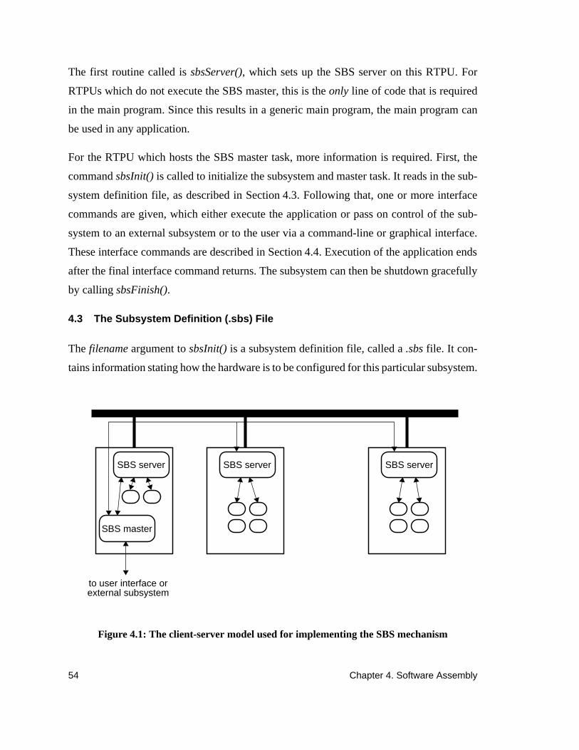
54 Chapter 4. Software Assembly
The first routine called issbsServer(), which sets up the SBS server on this RTPU. For
RTPUs which do not execute the SBS master, this is theonly line of code that is required
in the main program. Since this results in a generic main program, the main program can
be used in any application.
For the RTPU which hosts the SBS master task, more information is required. First, the
commandsbsInit() is called to initialize the subsystem and master task. It reads in the sub-
system definition file, as described in Section 4.3. Following that, one or more interface
commands are given, which either execute the application or pass on control of the sub-
system to an external subsystem or to the user via a command-line or graphical interface.
These interface commands are described in Section 4.4. Execution of the application ends
after the final interface command returns. The subsystem can then be shutdown gracefully
by callingsbsFinish().
4.3 The Subsystem Definition (.sbs) File
The filename argument tosbsInit() is a subsystem definition file, called a.sbs file. It con-
tains information stating how the hardware is to be configured for this particular subsystem.
SBS master
SBS server SBS server SBS server
to user interface orexternal subsystem
Figure 4.1: The client-server model used for implementing the SBS mechanism

4.4 Interface Commands 55
For most application users, this file will already be available, as it usually only needs to be
changed when default subsystem configuration parameters must be changed.
The .sbs file contains general information about the subsystem, including the name, the
state variable table to use, and the name of the RTPU on which to execute the SBS interface.
It contains a list of one or more RTPUs, which represent the RTPUs which the subsystem
can use to execute modules. It also includes options which can be modified to control fea-
tures of the RTPU, such as the type of real-time scheduling algorithm to use, and whether
or not the RTPU can be shared with other subsystems. Specific details of the fields and syn-
tax of the.sbs file are given in the Chimera program documentation [70].
4.4 Interface Commands
The key components of the master task are the interface commands. The interface com-
mands are designed so that any one of them can be executed in any order. For example, the
user may begin autonomous execution, but at some point in the session call up the com-
mand-line interface. From the command-line interface, the user may call up the external
subsystem interface, or alternately start up the external subsystem interface autonomously.
Next, we describe the different interfaces.
4.4.1 Command-line interface
The command-line interface allows a user to perform software assembly by typing in com-
mands at a prompt. The only interface command that needs to be added to the master task
is the following:
sbsCmdi(mysbs);
Execution of this command invokes the operating system service which provides a full-fea-
tured command-line interface. It allows the user to send commands to create tasks on any
of the subsystem’s RTPUs, turn them on and off as necessary, display real-time status in-
formation or state variable data, send signals to tasks, provide standard input and standard
output streams, and destroy tasks when they are no longer needed.

56 Chapter 4. Software Assembly
To accept the user’s commands, the SBS service displays the following prompt to the user:
SBSsbsname<rmodname>
wheresbsname is the name of the subsystem, obtained from the.sbs file, andrmodname is
the name of the default RMOD task to use in subsequent interface commands if no RMOD
name is specified. The default RMOD is automatically updated by the interface to always
be the RMOD to which the previous command was directed.
From this prompt, any of the subsystem commands may be given. The available commands
are outlined below (in alphabetical order). Syntactic details are given in the Chimera pro-
gram documentation [70].
clear Send aclear error signal to the RMOD.
display Show state variable table information. Many options are
available for selectively choosing which variables to display.
kill Destroy an existing task.
module Display module information or list modules available.
network Create an external subsystem network connection.
off Sendoff signal to RMOD.
on Sendon signal to RMOD.
quit Quit from the command-line interface. Note that this does not
necessarily exit the subsystem; it only passes control over to the
next interface command in the master task. It only causes the
subsystem to exit if the next line in the master task issbsFinish().
set View and modify module parameters and RMOD-dependent
configuration information.
spawn Create a new task in the subsystem, based on the information in
the configuration file for the specified RMOD.
status Display status information of one or all the tasks in the
subsystem. See the list of status information given below.

4.4 Interface Commands 57
The list of what is available in response to a status command generally includes more in-
formation than the users want. The users can issue astatus set command to configure the
interface to only display the status information they wish to see. The information that is cur-
rently available is the following:
rmod RMOD name of this task.
rtpu RTPU on which the task is executing.
tid Task ID.
S Type of task: ‘P’ for periodic, ‘Y’ for synchronous, ‘S’ for sporadic
server, ‘D’ for deferable server.
crit The criticality (i.e. priority) of the task.
state Current state of the task.
cycle Number of cycles executed since last ‘status’ command, or since
the task was turned ‘on’ if no previous ‘status’ command.
miss Number of missed cycles since laststatus command, or since the
task was turnedon if no status command was given before then.
refF The reference (desired) frequency in cycles per second of a task.
refT The reference (desired) period in seconds of a task. Note that
refT= 1/refF always.
mezF The average number of cycles per second executed. This value
should normally be within 1% ofrefF, unless there are missed
deadlines, in which case it will be lower thanrefF.
mezT The measured period of the task, as detected by the automatic
profiling. The profiling assumes that the period is a multiple of the
clock rate, and rounds to the nearest such multiple. However, if
refF is set to 400Hz, thenref-T should be set to 0.0025. If the tick
rate is 0.001 seconds, then there is an uneven split for the period;
i.e. in milliseconds that task would execute using periods 2, 3, 2, 3,
and so on, such that the average is 1/400 = 2.5 milliseconds. For
this reason,mezT is not necessarily1/mezF as it will be detected as
either 2 or 3, but not 2.5.
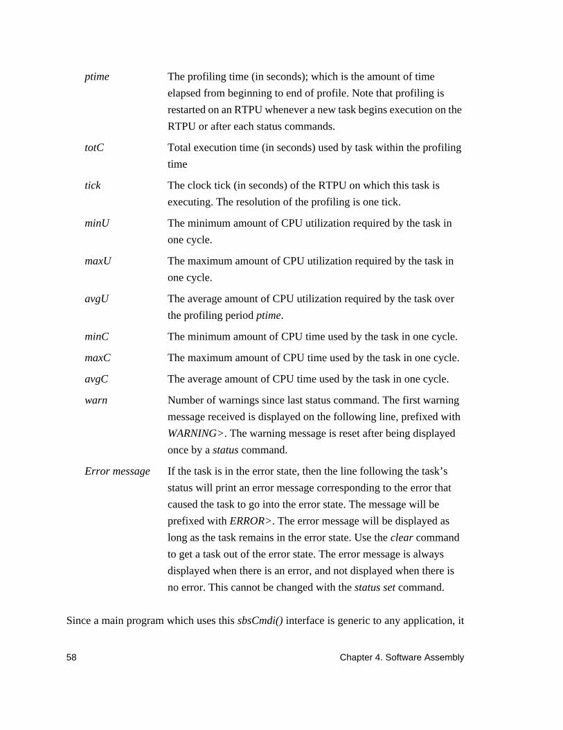
58 Chapter 4. Software Assembly
Since a main program which uses thissbsCmdi() interface is generic to any application, it
ptime The profiling time (in seconds); which is the amount of time
elapsed from beginning to end of profile. Note that profiling is
restarted on an RTPU whenever a new task begins execution on the
RTPU or after each status commands.
totC Total execution time (in seconds) used by task within the profiling
time
tick The clock tick (in seconds) of the RTPU on which this task is
executing. The resolution of the profiling is one tick.
minU The minimum amount of CPU utilization required by the task in
one cycle.
maxU The maximum amount of CPU utilization required by the task in
one cycle.
avgU The average amount of CPU utilization required by the task over
the profiling periodptime.
minC The minimum amount of CPU time used by the task in one cycle.
maxC The maximum amount of CPU time used by the task in one cycle.
avgC The average amount of CPU time used by the task in one cycle.
warn Number of warnings since last status command. The first warning
message received is displayed on the following line, prefixed with
WARNING>. The warning message is reset after being displayed
once by astatus command.
Error message If the task is in the error state, then the line following the task’s
status will print an error message corresponding to the error that
caused the task to go into the error state. The message will be
prefixed withERROR>. The error message will be displayed as
long as the task remains in the error state. Use theclear command
to get a task out of the error state. The error message is always
displayed when there is an error, and not displayed when there is
no error. This cannot be changed with thestatus set command.

4.4 Interface Commands 59
can be stored in a library itself, and thus an application can be assembled by way of this
interface without having to write any code.
4.4.2 External Subsystem Interface
The external subsystem interface allows any external program to communicate with the
master task via ethernet, and thus allow an external program to control the execution of
tasks in the subsystem. As with the command-line interface, only a single line of code is
required:
sbsNetwork(“portname”,mysbs);
The first argumentportname is a logical name that the master task is using to call the con-
nection. An external program can attach to this task through the network by using the same
portname as an argument toenetCreate(), which is part of theENET facility provided by
Chimera [70] as a user-friendly front-end to sockets.
The external subsystem can then issue commands by sending SBS messages through this
network connection. The SBS messages available for controlling the subsystem are de-
scribed in the Chimera program documentation, and offer all of the functionality available
with the command-line interface through the network interface.
Note that one of the commands for the command-line interface isnetwork, which in effect
allows the user to issue ansbsNetwork() command. The advantage of this feature is that the
user can start up the command-line interface, then after issuing a few instructions, follow-
up by letting an external subsystem assume control. When the external subsystem termi-
nates, or if the network connection is lost, control returns to the user via the command-line
interface. A similar effect can also be achieved which bypasses the necessity of giving the
initial network command at the command line by following thesbsNetwork() line with an
sbsCmdi() line. It is even possible to start-up with one external subsystem controlling this
subsystem, and part-way through the application dynamically disconnect and reconnect to
a different external subsystem, without ever having to shutdown any part of the control sub-
system.
As with the command-line interface, this network interface to external subsystems is ge-
neric, with only a single argument (theportname) to be provided. Since this argument can

60 Chapter 4. Software Assembly
easily be provided by an environment variable or by requesting input from a user, the main
program for a network interface to assembling software is generic and can be placed into a
library. This eliminates the need to write any new code when assembling an application
from existing modules.
4.4.3 Graphical User Interface
TheOnika Iconic Programming Environment[16] is a hypermedia graphical user interface
designed especially for assembling software. It uses the reconfigurable software paradigm
described in this thesis.
Onika is written to communicate with the master task through the external subsystem inter-
face, and therefore the interface command required in the master task is again only one line:
sbsNetwork(“chimera”,mysbs);
Onika is set up so that by default it uses a portname specified in a user environment vari-
able. However, different port names can be substituted during the actual process of con-
necting to Chimera. Since this same main program is used whenever Onika is used,
regardless of the application, the main program itself can be placed into a library and that
code need not be written again.
Control systems engineers and real-time systems engineers can use the “engineer’s level”
of the Onika interface, which greatly reduces development and testing time by presenting
an interface designed to facilitate control feedback loop programming. The “application
level” of the Onika interface, in which complete goal-oriented applications can be assem-
bled from software previously stored in libraries by the control systems engineers. is avail-
able to those programming the applications.
Onika and the Chimera SBS mechanism were developed in parallel and designed to coop-
erate. As a result, the same terminology is used within the two systems, and the systems
complement each other to provide an environment for software assembly that can be used
in programming and using virtual laboratories and virtual factories.

4.4 Interface Commands 61
4.4.4 Autonomous Program
The autonomous program interface commands are designed especially for the use in em-
bedded systems, where an interface to an external subsystem is not feasible. A user-inter-
face may be used to assemble, test, and debug an application. However, it is desirable that
the same software modules used in an open-architecture environment not need to be repro-
grammed for use in an embedded system. To address the need for creating such embedded
code, we have designed the autonomous program interface, which mirrors the capabilities
of the other software assembly interfaces, but allows the assembly instructions to be coded
in C then compiled and stored in an EPROM along with the software libraries. The C code
is may be placed directly into the themain program of the master task, or can be placed in
a separate module and called from the master task.
The complete set of commands available for controlling a subsystem autonomously are de-
scribed in the Chimera program documentation [70]. We present some of the more impor-
tant commands in this section.
To create a task on one of the RTPUs in the subsystem, the program issues thesbsSpawn()
command. This routine mirrors thespawn command that can be issued from the ofther soft-
ware assembly interfaces. It takes the names of a.rmod file and RTPU as arguments, and
creates a corresponding task in the subsystem. It returns a pointer to asubsystem task infor-
mation structure (called thestask structure), which is used in the subsequent SBS autono-
mous program interface commands.
Once the task is created and initialized, it moves to the OFF state (refer to Figure 3.10 on
page 33). Control signals are then sent to the task by calling thesbsControl() routine. The
types of signals that can be sent includeon, off, kill , andclear, which cause the task to tran-
sit into a new state. User input that is needed by the module and generally passed along
through a user interface can instead be coded in with the signal.
In order to perform dynamic reconfiguration of the system, it is often necessary to send
multiple signals at once. Multiple signals are sent to multiple tasks using thesbsReconfig()
command. The argument to this routine is an ordered list of signals to be sent. The items in
the list are processed sequentially in the specified order. Only a single acknowledgment

62 Chapter 4. Software Assembly
upon success is sent in response tosbsReconfig(). If an error occurs, then an error message
is returned which identifies which signal was being processed, and all subsequent signals
are not sent. Should the other signals be still need to be sent, then the master task can re-
issue thesbsReconfig() command, but only with those items that have not yet been pro-
cessed.
Certain aspects of the task can be controlled autonomously as well. For example, tasks are
generally created with a default frequency specified in that task’s.rmod configuration file
(see Section 3.8). Those default frequencies can be obtained using the commandsb-
sFreqGet() and reset using the commandsbsFreqSet().
A task may have module-dependent local information specified in its configuration file.
That information can also be obtained or overridden, by using the commands sbsGet() and
sbsSet() respectively.
The current status of a task in the subsystem can be obtained using thesbsStatus() routine.
Alternately, the status of all tasks can be obtained simultaneously usingsbsStatusAll(). The
information returned for each task is the same as the information returned by the command-
line interface, as described in Section 4.4.1.
Since the master task is responsible for instigating dynamic reconfigurations, it must wait
for a signal from a task in one configuration before issuing the interface commands for per-
forming the reconfiguration. The master task waits for a signal from one of the subsystem’s
RMOD tasks using thesbsSigWait() routine. The master task blocks until one of the spec-
ified signals is received. Signals which the master task is not interested in are automatically
ignored and discarded. In response to that signal, the master task wakes up and continues
execution with the next interface command. The master task can also execute conditionals
based on the value of the signal, or the task that sent it.
For example, the following code segment exits if there is an error signal, and continues
upon reaching any other signal:
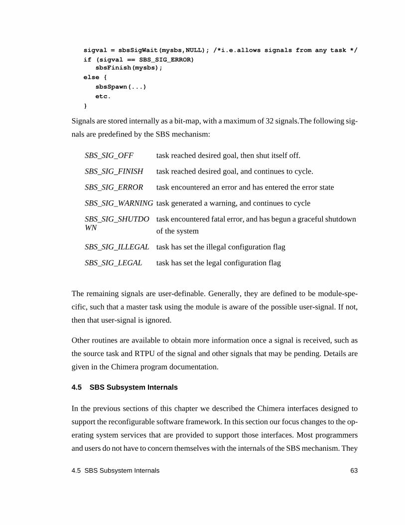
4.5 SBS Subsystem Internals 63
sigval = sbsSigWait(mysbs,NULL); /*i.e.allows signals from any task */
if (sigval == SBS_SIG_ERROR)sbsFinish(mysbs);
else {
sbsSpawn(...)
etc.
}
Signals are stored internally as a bit-map, with a maximum of 32 signals.The following sig-
nals are predefined by the SBS mechanism:
The remaining signals are user-definable. Generally, they are defined to be module-spe-
cific, such that a master task using the module is aware of the possible user-signal. If not,
then that user-signal is ignored.
Other routines are available to obtain more information once a signal is received, such as
the source task and RTPU of the signal and other signals that may be pending. Details are
given in the Chimera program documentation.
4.5 SBS Subsystem Internals
In the previous sections of this chapter we described the Chimera interfaces designed to
support the reconfigurable software framework. In this section our focus changes to the op-
erating system services that are provided to support those interfaces. Most programmers
and users do not have to concern themselves with the internals of the SBS mechanism. They
SBS_SIG_OFF task reached desired goal, then shut itself off.
SBS_SIG_FINISH task reached desired goal, and continues to cycle.
SBS_SIG_ERROR task encountered an error and has entered the error state
SBS_SIG_WARNINGtask generated a warning, and continues to cycle
SBS_SIG_SHUTDOWN
task encountered fatal error, and has begun a graceful shutdown
of the system
SBS_SIG_ILLEGAL task has set the illegal configuration flag
SBS_SIG_LEGAL task has set the legal configuration flag

64 Chapter 4. Software Assembly
are provided here for completeness and as a reference for readers interesting in designing
similar or compatible subsystem control mechanisms.
The SBS Subsystem Mechanism makes use of the Chimera IPC systerm services, as shown
in Figure 4.2. It does not contain any hardware dependent code.
Upon system start-up, the first thing to be initialized is an SBS server on each RTPU. This
server handles all subsystem requests for the RTPU which comes from a single master task
if the RTPU is used in exclusive mode. If the RTPU is used in shared mode, then it handles
the initial requests for each subsystem, and spawns duplicate SBS server tasks for each sub-
system using this RTPU.
During the server’s initialization, it sets up a message queue with the globally known name
“ rtpuname:sbsserver,” wherertpuname is the logical name of the RTPU.
The server also sets up a shared memory segment which includes the status information of
all tasks local to that RTPU. Status information is then available to the master task through
this shared memory.
Once the message queue and shared memory segment are initialized, the server blocks and
waits for an incoming message from a master task.
4.5.1 SBS Master Task Initialization
The SBS master task is initialized by calling sbsInit(), as described in Section 4.4.4. The
initialization routine first opens the specified.sbs configuration file. Syntactic details are
global sharedmemory
remotesemaphores
prioritizedmessage passingspin-locks
global state variabletable mechanism
SBS Subsystem Mechanism
Figure 4.2: Structure of Chimera real-time IPC mechanisms
express mail

4.5 SBS Subsystem Internals 65
given in the Chimera program documentation [70]. The following subsystem information
is specified in the.sbs file:
SUBSYSTEM: This entry specifies a logical name for the subsystem. This is espe-
cially useful in multi-subsystem applications where modules can be reused in
the different subsystems. Each module’s name can be prepended with the sub-
system name to identify it.
SVARFILE: Specifies a.svar file to be used to configure the global state variable
table (SVAR) mechanism, and should include the union of all input and output
ports that may be part of the subsystem. Further details of the SVAR mechanism
are given in Section 5.5.
MASTER: This optional entry is used to specify which RTPU will host all of the
communication mechanisms required for the SBS interface. If not specified, the
default is the RTPU on which the SBS master task is executing.
In addition to the above information, the following information is included for every RTPU
that is part of the subsystem:
RTPU: This entry specifies the logical name of an RTPU that is to be accessible to
the subsystem, meaning that tasks can be created and executed on that RTPU.
SCHEDULER: The SCHEDULER entry selects the type of scheduling strategy to
use. Currently it can be one of RM for rate monotonic, EDF for earliest-dead-
line-first, or MUF for maximum-urgency-first. The real-time scheduler is
described in more detail in Chapter 6. The Chimera RTOS also allows for
custom real-time scheduling; however the SBS interface currently does not pro-
vide any special provisions to interface with them.
USAGE: This field controls access to the RTPU. It must be either exclusive (the
default) or shared. In exclusive mode, no other subsystem can use this RTPU.
In the shared mode, other subsystems can make use of the RTPU. Care must be
taken when using the shared mode, since the real-time scheduling must cross
between multiple subsystems, and hence real-time scheduling analysis of the
66 Chapter 4. Software Assembly
subsystem or application may break down. The primary purpose of the shared
mode is to allow multiple subsystems to share I/O devices or SPPs, which must
be hosted by a single RTPU
ERRPRINT: This field controls the verbosity of error messages during run-time. It
must be either errors, warnings (the default), or none. In errors mode, only
errors are displayed on the user’s console at run-time. In warnings mode, both
errors and warnings are displayed at run-time. In none mode, neither errors nor
warnings are displayed during run-time. Note that regardless of the setting of
this variable, errors and warnings will always be displayed in response to a
status command given by the user.
MINFREQ, MAXFREQ: The minimum and maximum frequency of a task expected
on this RTPU, in cycles per second (Hz). Default is 1.0 Hz. These options are
used to control the scaling of the criticality of the task’s frequency. All tasks
with frequencies less than or equal to MINFREQ assume the lowest criticality,
and all tasks with frequencies greater than MAXFREQ get the highest critical-
ity. The criticality of tasks in between are scaled logarithmically. If too small a
range is given between MINFREQ and MAXFREQ, then tasks outside the
range will have the same criticality, and hence decrease real-time scheduling
performance. Similarly, if the range is too large, then tasks in between may have
the same criticality, and hence decrease scheduling performance. For example,
in MINFREQ is 0.1, and MAXFREQ is 1000.0, then the frequencies 25 Hz and
30 Hz map into the same criticality value (the number of criticality values is
scheduler dependent). On the other hand, if MINFREQ is 10.0, and MAXFREQ
is 100.0, then tasks with frequencies of 25 Hz and 27 Hz might still get different
criticalities. With the default Chimera 3.0 scheduler, 62 criticality values are
used (values 0 and 63 are reserved by the SBS software).
Once the configuration file has been read, the initialization routine proceeds to create the
necessary IPC mechanisms. First, an incoming message queue for reply messages from

4.5 SBS Subsystem Internals 67
SBS servers is created. A remote semaphore is initialized, which will allow the master task
to block while waiting for signals to arrive from RMOD tasks.
For each RTPU specified in the .sbs file, the master task attaches to that RTPU’s SBS server
message queue, then sends a message requesting use of the subsystem. If the subsystem is
to be used in exclusive mode, and no other subsystems have reserved the RTPU, then the
server sends a reply allowing the master task to continue. If the RTPU is already in use by
another subsystem, then an error is returned. If the subsystem requests that the RTPU be
used in shared mode, and no other subsystems are using the subsystem in exclusive mode,
then the SBS server spawns a duplicate server task, and returns a message indicating the
new message queue to which the master task should send all subsequent messages.
When the server receives the message, it updates its internal tables to reflect that it is now
connected to a master task, then blocks waiting for commands from that task.
The entire setup process described above is totally transparent to the programmer and user.
They only have to ensure thatsbsInit() is called by the master task, and thatsbsServer() is
executed on every other RTPU.
Once the master task is initialized, interface commands as described in Section 4.4 can be
issued to execute the tasks on the RTPUs. The internals of these commands are now de-
scribed.
4.5.2 Spawn: creating a new task
A new task is created by issuing thesbsSpawn() command, or sending a spawn interface
command via one of the other interfaces. For these other interfaces, the command is con-
verted intosbsSpawn() internally.
The two arguments tosbsSpawn() are the target RTPU and the name of a.rmod file. A mes-
sage is sent to the SBS server on the target RTPU which includes the name of the file. Upon
reception of the message, the server spawns a new task locally, with the filename as the ar-
gument. The new task then reads the.rmod file, and configures itself accordingly by attach-
ing to the SVAR table and setting up its local state to reflect the task type, frequency and
SVAR variables specified in the file. Symbol translations are performed based on the name

68 Chapter 4. Software Assembly
of the name of the module which provides the C code for executing the different methods
through the lifetime of the task. For example, if the module name issample, then symbol
translations are performed for the routinessampleInit(), sampleOn(), sampleCycle(),etc.
The new task then reads thein-consts from the SVAR table, and executes thesampleInit()
routine, as was shown in Figure 3.10 on page 33, and described in Section 3.6. Whensam-
pleInit() returns, a message is sent back to the master task acknowledging success of the
spawn command. Should an error occur, then an error is sent back instead and the initial-
ization of the task aborted. There is no error recovery routine for the initialization routine.
Instead, since this is still non-critical execution of a task, the problem should be fixed, and
the task re-spawned.
4.5.3 Sending Signals to Tasks
Once a task is created, a variety of signals can be sent to it, such ason, off, kill, andclear,
using eithersbsControl() or one of the corresponding interface commands which in turn
call sbsControl(). The internals for sending each of these signals is the same. A message is
sent to the SBS server on the RTPU of the task which should receive the signal. The server
applies the signal to the internal finite state machine it maintains for the task (which is based
on the internal port-based object structure shown in Figure 3.10 on page 33), and ensures
that the signal is valid. Examples of invalid signals include sending anon signal to a task
that is already cycling, or sending aclear signal to a task that is not in theERROR state.
These signals are ignored, and an error returned to the master task. Valid signals are passed
along to the task, and the task makes a transition according to Figure 3.10 only after com-
pleting execution of its current component. If the task is not executing one of its compo-
nents, then the transition occurs immediately. This method of transitioning ensures that if
a task begins executing its cycle component (or any other component for that matter) it
completes the execution and leaves the system in a known state before transitioning to a
new state.
If an error occurs during the transition of states (which usually would occur as a result of
executing one of the methods of the object in response to the signal) then the task sends
4.6 Summary 69
back an error message to the master task, otherwise an acknowledgment of success is sent
to the master task.
With this synchronization, the master task must always wait for a reply before sending any
other signals. This type of synchronization despite the blocking of the master task was se-
lected for several reasons:
• If a problem occurs, the task causing the problem is quickly isolated.
• The master task is not involved in the critical execution of tasks; the critical
tasks continue to execute at high priority.
• If several tasks need to be swapped at the same time, then thesbsReconfig()
routine should be used to send multiple signals, and avoid the overhead of
communicating between the master and server tasks.
The master task can also receive signals synchronously. Generally after the master task has
created and turned on some tasks, it waits for a return signal to indicate the status of the job,
such as completed, error, or reaching some kind of midpoint. The signals that are available
are described in Section 4.5.3.
The master task can setup signal masks to ignore certain signals, either on a subsystem-
wide basis or an individual per-task basis. When the master task performs ansbsSigWait(),
then it blocks on the remote signal semaphore that was created during initialization.
A task sends a signal by using thesbsSigSend(). When it does, it first checks the current
signal mask. If that mask has not been set, then it defaults to checking the subsystem-wide
signal mask instead. If the signal is not masked, then the remote semaphore is signalled,
causing the master task to wake up and continue with its execution. The master task knows
which task and which signal were sent, by checking the return value of thesbsSigWait()
routine.
4.6 Summary
Reconfigurable software can be used to support software assembly, where, given a library
of software modules, the modules can be integrated and executed in real-time without the
need for any glue code. In this chapter various interfaces for such software assembly were

70 Chapter 4. Software Assembly
presented, including command-line, graphical user interface, external subsystem, and au-
tonomous programs. Details of sending signals between the master task, server tasks, and
user tasks were also presented.
5.1 Introduction 71
Chapter 5
Multiprocessor Real-Time Communication
5.1 Introduction
High performance real-time communication and synchronization is required in multipro-
cessor real-time applications, such as robotics, process control, and manufacturing. The
communication must be predictable, such that no signals or messages are lost. Worst-case
execution and blocking times must be calculable, so that real-time analysis of task sets us-
ing multiprocessor communication is feasible. Also, the communication mechanisms must
be efficient and have little overhead, so that they do not dominate CPU utilization.
Previous research has concentrated on real-time multiprocessor communication using spe-
cialized network hardware [74], or require shared memory hardware which guaranteed
bounded communication time [11] [50]. However, none of these protocols support the use
an open-architecture bus, such as the VMEbus, which was not originally intended for real-
time applications. The protocols require that processors have software control of dynamic
priorities to use the bus; however, the VMEbus only has fixed priority which is set in hard-
ware. We first provided practical real-time communication mechanisms especially for such
backplanes in Chimera II [69]. The mechanisms included dynamically allocatable global
shared memory (SHM), remote semaphores (SEM), and prioritized message passing
(MSG). Due to the non-real-time aspects of the bus, these mechanisms were designed pri-
marily for soft real-time communication. These mechanisms form the basis for the global
state variable table (SVAR) mechanism, in which the amount of data that must be trans-
ferred between real-time tasks is minimized and bounded. As a result, a bounded waiting
time for real-time communication is possible, even without dynamic software control of
priorities on the bus.
Furthermore, in order to use any communication mechanism in a reconfigurable software
application, it is necessary that the communication be transparent across processors. The

72 Chapter 5. Multiprocessor Real-Time Communication
SHM, SEM, and MSG all provide this capability by using a novel underlying communica-
tion mechanism, called express mail, which allows non-blocking communication between
the kernels on each RTPU in a multiprocessor system. The SVAR mechanism goes a step
further and not only supports processor transparency, but also supports port-based objects.
It allows for both static configuration and dynamic reconfiguration without the need for any
glue code, allowing it to be used as the basis for software assembly.
The remainder of this chapter describes the IPC mechanisms that have been developed to
support reconfigurable real-time applications, and is organized as follows: a review of an
open-architecture backplane is given Section 5.2 in order to highlight the target architecture
for our communication mechanisms. In Section 5.3 the Chimera express mail mechanism
is described, which is the basis for the multiprocessing capabilities of Chimera as it pro-
vides real-time communication between the kernels on different RTPUs. In Section 5.4 ba-
sic Chimera IPC mechanisms are described, which include dynamically allocatable global
shared memory, remote semaphores, and prioritized message passing. In Section 5.5 a
more elaborate communication mechanism is described, call the state variable table mech-
anism, which has been designed especially for real-time communication between reconfig-
urable port-based objects. In Section 5.6 mechanisms for real-time communication to
external subsystems are described. Finally, in Section 5.7 the multiprocessor communica-
tion mechanisms which have been designed into Chimera to support reconfigurable soft-
ware are summarized.
5.2 Review Of A Typical Backplane Configuration
An RTPU is typically a single-board computer or multiprocessing engine (e.g. [23]), which
has its own general purpose processor, local memory, timers, and both master and request
access to the common bus.Master access refers to the ability of the RTPU to request the
use of a common bus, and initiate transactions on that bus. Arequest access refers to the
RTPU’s ability to respond to the request of other RTPUs. The RTPU executes a real-time
kernel which provides multitasking and hardware independence to the underlying hard-
ware. The RTPU’s local memory is dual ported so that it can also be accessed by other
RTPUs via the backplane. The memory can also be accessed from at least two physical ad-
dress spaces: the first is thelocal base address which is the address used by the local pro-

5.2 Review Of A Typical Backplane Configuration 73
cessor; the second is the remote base address which is used by other RTPUs on the
backplane1. Although these two addresses could be the same, they usually are not. Some
RTPUs have multiple remote base addresses, in cases where the backplane in use has mul-
tiple address spaces. For example, the VMEbus [44] has both A24 (i.e. 24 address lines
used) and A32 (i.e. 32 address lines used) address spaces, which are distinctly separate. An
RTPU must have a remote base address within at least one of those address spaces, but op-
tionally it can have an address in both address spaces.
A typical multiprocessor backplane configuration was shown in Figure 3.3 on page 25.
Each RTPU is in a different slot of the backplane. Sample local and remote base addresses
of each RTPU’s memory are also shown. The addresses are static for a particular hardware
configuration, they are always knowna priori, and made available to all the RTPUs in the
system during bootup. Unlike LANs, where new computers can be added to the network
without shutting the remaining computers, all RTPUs on a backplane must be powered
down whenever an RTPU is added or removed. We therefore can assume that the maximal
set of RTPUs, and their remote base addresses, are known to all RTPUs during the bootup
process. Obviously, some RTPUs may not be running even though they are powered; nev-
ertheless, their addresses are still known by other RTPUs.
In order to perform a memory transfer across the bus, an RTPU must first arbitrate for use
of the bus. If multiple RTPUs request the bus simultaneously, then only one of them is
awarded the bus. On the VMEbus there are two possibilities: round-robin or fixed priority.
Predictable real-time communication has been performed using the round-robin
technique [66]. Unfortunately, the VMEbus hardware restricts to a maximum of four bus
masters, and thus the combination of RTPUs, bus adaptors, and special purpose processors
cannot be more than four. In addition, since supporting the round-robin mode is optional,
not all hardware can make use of it. These two factors are far too limiting for most appli-
cations; thus, we must use the alternative, which is a fixed priority arbitration scheme. With
this scheme each bus master is assigned a fixed priority on the bus, and when a task on that
1 Theremote base address is often referred to by the bus name instead; e.g. for the VMEbus it isoften known as theVME base address, while for the Multibus II it is known as theMultibus baseaddress.
74 Chapter 5. Multiprocessor Real-Time Communication
RTPU requests use of the bus, it then inherits the priority of the RTPU. The problem with
this scheme is that a low priority task on a high priority RTPU may indefinitely lock out a
higher priority task on a lower priority RTPU. In order to provide practical real-time com-
munication mechanisms for the VMEbus, this issue must be addressed.
In addition to providing dual-ported memory, most RTPUs have some other hardware sup-
port for multiprocessor synchronization. One common form is the atomicread-modify-
write (RMW) operation. An RMW operation involves reading the current value of a mem-
ory location, and possibly updating it with a new value, implemented in such a way that it
is guaranteed to be atomic. For example, the MC68030 single board computers used to im-
plement Chimera support thetest-and-set (TAS) and compare-and-swap (CAS)
instructions [43].
There are two common methods of implementing these RMW instructions over a shared
bus, only one of which works correctly. The correct way is for the processor to lock both
the shared bus and the local bus of the remote RTPU which owns the memory. This method
ensures that no other processor can access the same memory location, as both the backplane
bus and processor’s local bus are locked. An alternate (and faulty) method of implementing
these instructions is to lock the shared bus only1. In such a case, an RTPU performing an
RMW operation on remote memory will successfully lock out all other RTPUs on the bus.
However, since the RTPU which owns the memory does not go through the bus to access
the local memory, it is not locked out. Hence this violates the criterion of being atomic, thus
making the instruction useless for performing atomic operations. The method of imple-
menting the RMW instruction over the bus is usually dependent on the manufacturer of the
RTPU, and not on the processor itself, but sometimes is jumper selectable.
1 The most reliable way of checking which implementation of an RMW instruction is used by a par-ticular model of RTPU is to use a bus analyzer (e.g. VMETRO VBT 321 for a VMEbus [77]) andtrace an RMW operation. Also, different RMW operations may be implemented in a different wayfor the same RTPU. For example, the Ironics IV3230 which has an MC68030 processor properlyimplements the TAS instruction by holding the address strobe, which results in locking the remoteRTPU’s local bus, thus providing the proper atomicity of the operation. However, the CAS instruc-tion is implemented by locking the VMEbus only, which means that although other RTPUs cannotgain access to the memory through the VMEbus, an RTPU which can access that memory locally(which is generally the case for at least one RTPU in the system) can still modify the memory, thuscreating a race condition and causing the instruction to not be atomic.

5.3 Express Mail 75
A second form of synchronization usually made available by the hardware is interrupts.
These generally come in two forms: bus interruptsandmailbox interrupts. The implemen-
tation of the bus interrupts is hardware dependent. For example, the VMEbus has seven lev-
els of interrupts (IRQ1 through IRQ7), with level 7 having the highest priority. Several
limitations occur with VMEbus interrupts, such as the limited number available, and the
restriction that the same processor must handle all interrupts on the same level. The bus in-
terrupts are thus a valuable resource which must not be wasted. In addition, many I/O de-
vices on the bus also use the bus interrupts, and hence the RTPUs may not be able to use
them among themselves. An increasingly popular alternative are mailbox interrupts. These
interrupts do not require any special support from the shared bus. Instead, an RTPU which
wants to interrupt another RTPU performs a memory operation over the bus. The receiving
RTPU translates this memory write into a local interrupt for the RTPU. The number of
mailbox interrupts available on an RTPU is hardware dependent. However, we show in
Section 5.3 that, as long as the hardware supports at least one mailbox interrupt, an arbitrary
number of mailbox interrupts can efficiently be multiplexed in software. Using mailbox in-
terrupts for all interprocessor interrupts is recommended, as it frees the bus interrupts to be
used exclusively by I/O devices and special purpose processors which do not have the abil-
ity to become a bus master.
In the remainder of this chapter, a variety of communication mechanisms are presented,
which have been developed especially for backplane interprocessor communication and
synchronization for reconfigurable systems.
5.3 Express Mail
Reconfigurable software modules must be able to execute on any of the RTPUs in a multi-
processor system. Since these modules must also be designed independent of the target
hardware setup, the interprocessor communication between the target RTPUs must be
transparent to the software module.
The necessary transparency for the communication has been achieved by developing Chi-
mera as a multiprocessor operating system, in which the kernels on each RTPU communi-
cate with each other. All of the hardware dependencies of the communication can then be

76 Chapter 5. Multiprocessor Real-Time Communication
hidden within this lower level communication, so that the user-level communication mech-
anisms, as described in the subsequent sections of this chapter, are transparent.
When the real-time kernels on two RTPUs communicate with each other, it is necessary
that the kernel on one RTPU does not block while waiting to synchronize with the other
RTPU, as remote kernel blocking results in increased unpredictability when scheduling the
local real-time tasks. In addition, the communication should be fast and require minimal
overhead, so as not to lock up the RTPU or shared resources such as the bus for any ex-
tended period of time.
In this section, theexpress mail mechanism (abbreviatedXM) that was developed and im-
plemented in Chimera is described. It is the single most important feature that makes Chi-
mera a true multiprocessor real-time operating system. It provides high-performance
communication, targeted to a shared-memory architecture with a small number of RTPUs
(where “small” is defined as less than 10), as is typical with most VMEbus-based systems
(see Figure 3.3 on page 25). For systems with many more processors, they should be di-
vided into multiple subsystems, each with its own isolated bus. The buses are isolated by
the use of gateways, which allow for the exchange of data between the subsystems, but do
not allow the local bus usage of one subsystem to interfere with the bus usage of the other
subsystem. The inter-subsystem communication described in Section 5.6 can then be used
to communicate between these different subsystems.
The mechanism is called express mail because it is based on setting up structured mailboxes
on each RTPU. These mailboxes are the only remote memory locations known to a kernel
at bootup time. A kernel sends a message to another kernel by placing the message in the
other kernel’s mailbox, then sending a mailbox interrupt to notify the remote RTPU of the
pending message. An express mail server reads and processes the message. The server pro-
vides several services: it acts as a name server for dynamically setting up user-level inter-
processor communication channels; it provides system information about the local RTPU;
it signals or forwards messages to local tasks, and is used to implement an extended file
system, where a task on one RTPU can transparently access the file system that is local to
a different RTPU.

5.3 Express Mail 77
5.3.1 Mailbox Structure
The XM mailbox consists of several components. It includes analive status value,ntasks
wakeup words,nrtpu mailbox headers,nrtpu mailbox buffers of sizebufsize, andnmbox
mailbox interrupts, wherentasks is the maximum number of tasks for an RTPU,nrtpu is
the number of RTPUs in the system, andnmbox is an arbitrary number of unique mailbox
interrupts that can be sent to the RTPU. A copy of this mailbox structure exists on each
RTPU. The memory map of an XM mailbox withntasks=8,nrtpu=3,bufsize=1Kbyte, and
nmbox=8 is shown in Figure 5.1.
Thealive status value shows the current status of the RTPU. This value allows one RTPU
to check whether or not an RTPU is executing before attempting to send a message.
Thewakeup words are used for interprocessor blocking. It allows a task on one RTPU to
block, while waiting for a task on the same or different RTPU to wake it up.
Themailbox headers contain information about mail messages sent between RTPUs; the
messages themselves are stored in themailbox buffers. The structure of each mailbox
xmalive
xmmbox interrupt
base+0base+4
xmwakeup
base+36
xmheader[0]
xmbuffer[2]
locations
base+68
base+100
base+132
base+1156
base+2180
base+3204
base+3268
bidin
out*xmalive
*xmwakeup*xmheader*xmbuffers*xmmbox
048121620242832
for incoming messagesfrom RTPU 2
xmbuffer[1]for incoming messages
from RTPU 1
xmbuffer[0]for incoming messages
from RTPU 0
xmheader[1]
xmheader[2]
Figure 5.1: Memory map of express mail buffers for a system with 3 RTPUs.
78 Chapter 5. Multiprocessor Real-Time Communication
header is shown in the blowup portion of Figure 5.1. The fields in the structure are defined
as follows:
Thexmalive, xmwakeup, xmheaders, xmbuffers, andxmmbox pointers are usable by the XM
routines on the local RTPU, and point to the different components of the XM mailboxes on
remote RTPUs.
Themailbox interrupts are used to expand the interrupt capabilities of the RTPUs. A mail-
box interrupt refers to a write operation into a remote RTPU’s memory which is converted
into a local interrupt on that RTPU. Its use eliminates the need to use VMEbus interrupts
for synchronization between RTPUs, freeing them for use by I/O devices. Most RTPUs,
however, only support one or two mailbox interrupts. To expand on that number, the ex-
press mail mechanism also provides a number of mailboxes. A mailbox interrupt is then
sent by first writing to one of these locations, then by a write to a secondtrigger location,
which is one of the hardware supported mailbox locations. Therefore, when using the ex-
press mail system, two write operations are required to send a mailbox interrupt. For
RTPUs that do not support mailbox interrupts at all, the trigger can instead be a bus inter-
bid The RTPU ID of the currentxmheader, such that
xmheaders[bid]=bid.
in A pointer, relative toxmbuffer[bid], into the intended recipient’s
buffer, for the next message.
out A pointer, relative toxmbuffer[bid], into the buffer of messages
received from RTPUbid, which is where the next message
retrieved should be read from.
*xmalive A pointer to the alive status value on RTPUbid.
*xmwakeup A pointer to the XM wakeup words on RTPUbid.
*xmheaders A pointer to the XM headers on RTPUbid.
*xmbuffers A pointer to the XM buffers on RTPUbid.
*xmmbox A pointer to the mailbox interrupt locations on RTPUbid.

5.3 Express Mail 79
rupt, and thus a combination of a write operation and a single bus interrupt is used to im-
plement the arbitrary number of mailbox interrupts.
The express mail mechanism reserves use of three of the mailboxes: one for resetting a re-
mote RTPU, a second for signalling that a task should wakeup, and the third for signalling
that a message has been placed in an XM buffer. The remaining mailboxes are user-defin-
able.
Given the above structure of mailboxes for implementation of the express mail, the follow-
ing functions can then be implemented. These functions are generally made from other sys-
tem calls, and not by user code. For example, theshmCreate() call, which sets up a shared
memory segment on an RTPU, sends an express mail message to the RTPU on which the
shared memory should be allocated. The express mail messages are transparent to the pro-
gram which callsshmCreate().
xmInit: Initialize the cross reference pointers to the XM buffers of all the RTPUs.
This routine is called during the kernel start-up. The base address of the shared
memory to be used for the mailbox structure on each RTPU is passed as an argu-
ment by the kernel, based on the current hardware setup of the system.
xmInitLocal:Initialize the local XM buffer, by setting all the indexes to 0, indicat-
ing empty buffers. The XM mechanism defines three mailbox interrupts:
XM_MBOX_RESET, which signals the board to do a warm boot;XM_MBOX_-
SIGBUF, which signals that an XM message has been placed into a buffer; and
XM_MBOX_SIGWKUP, which indicates that a task that is blocked must be sig-
nalled to wake up. ThexmInitLocal() routine installs the interrupt handlers for
each of these possible mailbox interrupts. The other mailbox interrupt locations
are user-definable, using thexmMboxInstall() routine described below.
xmBlock:The task calling this routine blocks until the reception of an xmWakeup()
signal. It performs aP() operation on a local semaphore. The local semaphores
are stored in an array called _xmwaitsem[ntasks]; note that this array is not in
the shared memory express mail structure, since the values are all local.
80 Chapter 5. Multiprocessor Real-Time Communication
xmWakeup:Send a wakeup signal to a task on a remote RTPU. If that task is not
blocked, then the signal is ignored. When this routine is called, the wakeup bit
for the target task is set, and anXM_MBOX_SIGWKUP mailbox interrupt is
sent to RTPUbid. When the interrupt handler on the target RTPU is called, it
performs aV() operation on the local semaphore that the blocked task is waiting
on. The task that callsxmWakeup does not block, thus does not wait for any
acknowledgment that the remote task has been signalled.
xmWrite:Write a message into the XM buffer of the destination RTPU. Since the
local RTPU has a reserved mailbox for itself on the destination RTPU, there is
no need to lock out any of the other RTPUs. The problem of multiprocessor syn-
chronization is thus reduced to one of local synchronization, and hence elimi-
nates the multiprocessor synchronization problems. Once the message has been
placed in the remote buffer, thein pointer on the remote RTPU is updated, and
anXM_MBOX_SIGBUF mailbox interrupt is sent to the remote RTPU. A task
on the remote RTPU (which in Chimera is always the XM server task, although
it does not have to be) then wakes up and performs anxmRead. As far as the
express mail mechanism is concerned, messages are untyped, and are placed in
the buffer on a first-come-first-serve manner. It is the responsibility of the rou-
tines which make use of the express mail to add semantics to the messages and
signals that are sent through this mechanism. Priority-based communication
(such as user-level message passing) is obtained by first using the express mail
to set up the prioritized queues, and then bypassing the express mail once the
queues have been created.
xmRead:This routine is called by the XM server in response to receiving and
XM_MBOX_SIGBUF mailbox interrupt. Every XM buffer is checked for a pos-
sible message. The check is simple, where a message is present ifin != out. It
is possible that more than one buffer holds messages, as the mailbox interrupts
are not stacked (i.e. if multiple RTPUs send the same mailbox interrupt, only
one will be received). Therefore, it is necessary to check every mailbox for
incoming messages. Since there is only one comparison required per incoming

5.3 Express Mail 81
mailbox to check for messages, and there is only one mailbox per RTPU in the
system, the overhead for checking all the mailboxes is low and bounded. Read-
ing the message is a simple matter of first retrieving the number of bytes to
copy, which is at the location pointed to by theout pointer, then copying the data
from the mailbox to the memory pointed to by the argumentmsg. Once the data
is read, theout pointer is updated. Ifin != out, then there is still data to be read.
xmMboxSend:This routine sends a mailbox interrupt to a destination RTPU. When
it sends the interrupt, it places the non-zero value in the buffer, which is passed
along to the interrupt handler on the remote RTPU. ThexmWrite andxmWakeup
calls automatically call this routine to send theXM_MBOX_SIGBUF and
XM_MBOX_SIGWKUP interrupts respectively. For any of the user-defined
mailbox interrupts, this routine must be called explicitly.
xmAlive:This routine checks if the RTPU bid is executing. If it isn’t it returns an
error. This routine is automatically called byxmWrite andxmWakeup before
performing any remote operations.
xmLock, xmUnlock:These routines use the atomic test-and-set instruction to pro-
vide the lowest level locking available in a multiprocessor system, which is a
spin-lock. A time-out mechanism is built-in so that obtaining a lock can be time-
bounded.
The exact syntax for the Chimera implementation for the functions is given in the Chimera
program documentation [70].
The total shared memory consumed by the mailbox structure on each RTPU is
size = 4*(1+ntasks+nmbox) + nrtpu*(sizeof(xmheader)+bufsize) (5)
wheresizeof(xmheader) is 32 bytes. For the example shown in Figure 5.1, the total is 3268
bytes per RTPU. Note that this is with 1KByte buffers. The size of the buffers should be
chosen based on the sizes of the messages to be sent. The only time thatxmWrite() blocks
waiting for another RTPU is if the remote RTPU’s XM buffer is full. In Chimera, the ex-
press mail is used for system messages which are usually less than 32 bytes long, with the

82 Chapter 5. Multiprocessor Real-Time Communication
occasional longer message of approximately 256 bytes. By setting the buffers to 1KByte or
longer, we have found that such blocking has never occurred in our applications.
5.3.2 Interfacing with the Host Workstation
One major advantage of using express mail is that an RTPU does not block waiting for an-
other RTPU to complete its computation. For this reason, even if a single-board-computer
involved in the express mail communication is non-real-time, it does not affect the real-
time performance of the RTPUs communicating with it. By taking advantage of this char-
acteristic of the XM mechanism, the host workstation can be viewed as an RTPU within
the real-time environment, even though it is non-real-time. Processes and an XM server on
the host workstation can communicate with the real-time kernels on the RTPUs using the
same mechanism. The result is that most of the IPC mechanisms in Chimera, including the
global shared memory, remote semaphores, message passing, global state variable table,
and subsystem interface commands not only work between tasks on RTPUs, but also work
to communicate between the host workstation and the real-time tasks.
Involving the host workstation in the express mail communication does require some addi-
tional support because of differences in the host operating system. First, the memory of the
host workstation is often reserved by the host operating system, which uses virtual memory
to page data in and out of that memory. This is not suitable for the XM mailboxes. There-
fore the memory required by the host workstation is stored remotely, using one of the fol-
lowing methods:
• If there is a gateway between the host workstation and the target bus, and that
gateway has memory, then store the host’s XM mailboxes in that memory.
• If there is no gateway, but the target bus has a memory board installed, then
store the XM mailboxes in that memory.
• If there is neither a gateway nor a memory board, then store the XM mailboxes
in the memory of one of the RTPUs in the system.
In addition, the host workstation generally does not support mailbox interrupts, thus requir-
ing that bus interrupts be used. The bus interrupt causes an interrupt handler on the host
workstation to be called, which in turn sends a signal to the XM server.

5.3 Express Mail 83
Often, the host workstation does not support the TAS instruction, which is required for
proper mutual exclusion usingxmLock. To alleviate this problem, thexmLockFix routine
was developed, which implements a two-step synchronization to guarantee mutually exclu-
sive access to shared memory between the host workstation and the RTPUs. The algorithm
combines the use of the TAS hardware synchronization used forxmLock with a software
synchronization presented in [60].
1: struct xmlock {2: byte rtpumutex;3: byte hostmutex;4: byte turn;5: byte flag[2];6: }7:8: enum xmwho {RTPU, HOST};9:10:xmLockFix(struct xmlock *xml,enum xmwho mytype) {11: if (mytype == RTPU)12: while (tas(&xml->rtpumutex) != 0) delay(0.0001);13: else14: while (bset(&xml->hostmutex) != 0) delay(0.0001);15: xml->flag[mytype] = 1;16: xml->turn = NOT mytype;17: while (xml->flag[NOT mytype] && xml->turn == NOT mytype)18: delay(0.0001);19: return;20:}21:22:xmUnlockFix(struct xmlock *xml,enum xmwho mytype)23: if (mytype == RTPU)24: xml->rtpumutex = 0;25: else26: xml->hostmutex = 0;27: return;28:}
In lines 11 through 14, the first lock is obtained. If it is an RTPU trying to obtain the lock,
then thertpumutex lock is obtained, using theTAS instruction, which is guaranteed to be
atomic among multiple RTPUs that support the instruction. If it is the host trying to obtain
the lock, which does not have theTAS instruction, then theBSET (byte-set) instruction is
used to obtain thehostmutex lock, which is guaranteed to be atomic on a single processor,
but not on multiple processors.

84 Chapter 5. Multiprocessor Real-Time Communication
When a task reaches line 15, then it is guaranteed that there is a maximum of two tasks that
can by trying to obtain the second lock: one task from one of the RTPUs, and one task on
the host workstation. At this point, since the host does not support the TAS instruction, we
use the two-process software mutual exclusion algorithm from [60], which is shown above
in lines 15 through 18. Only one of those two tasks can proceed at a time, and the other
waits until the task getting the lock callsxmUnlockFix().
The express mail also allows for the implementation of an extended file system, where any
task on any RTPU can use of the file system on the host workstation. This is accomplished
by making use the express mail to implement transparent remote procedure call versions of
system calls such asopen(), read() andwrite(). The result is that all tasks on any RTPU can
share the same file system in a transparent manner, thus ensuring the hardware and appli-
cation independence of software modules that require use of the filesystem.
5.4 Basic IPC
The basic interprocessor communication (IPC) facilities required to support the more ad-
vanced reconfigurable software communication mechanisms are dynamically allocatable
global shared memory, remote semaphores, and message passing. Chimera provides a con-
venient hardware-independent interface to these IPC mechanisms by designing them as ob-
jects which make implicit use of the express mail described in the previous section.
The operating system takes care of the details such as the physical locations and address
spaces of the RTPUs. The interface to the different mechanisms is similar: acreate routine
is to be called by only one task to create the object. Once created, any other task may attach
to it to make use of the shared object. The task that creates the object is already attached to
it. Most objects require some initialization, and thus the create/attach separation is designed
to provide a clear distinction for which task is responsible for initializing, and if necessary
maintaining the resource. Once attached, other primitives are available for accessing the
object, depending on the object type. When a task if finished, it can detach from the object.
The final task to finish with the resource can then destroy it. The interfaces for the basic
IPC are described in this section.

5.4 Basic IPC 85
The basic IPC objects are created dynamically with a call to anxxxCreate() routine, where
xxx is replaced by the module nameshm, sem, ormsg for the shared memory, remote sema-
phores, and message passing IPC respectively. There is no need to pre-specify these ob-
jects. Each object has a logical name in two parts, the first part is the name of the RTPU or
memory board on which the object is to be physically located, and the second is a name for
the object. The compounded name has the form:
“ rtpuname:resourcename”
and is used only for thexxxCreate andxxxAttach routines. There is no need to specify any
physical addresses of the RTPUs, thus making the code much more portable. A pointer to
the object is returned by the create or attach routine, and that pointer is then used by the
local task in all subsequent accesses to the object. Since the resources are allocated dynam-
ically and accessed through hardware-independent interfaces, they can be configured based
on application information at run-time, which is a necessary feature for using these mech-
anisms with reconfigurable software.
Rtpuname is the logical name of the RTPU in the system whose memory is to be physically
used to store the shared object. The memory on a bus adaptor joining the host workstation
and real-time VME chassis, if available, can also be used by using the RTPU name of the
host workstation. IPC segments can also be created on memory boards in the system, by
specifying the logical name of the memory board instead of the RTPU name.
The IPC mechanisms can also be used for local communication without any modification
or special casing. Therefore, when one task communicates with another task, it makes no
difference whether the two tasks reside on the same RTPU or different RTPUs (except pos-
sibly in speed of transfers over a bus), which is another necessity for IPC in a reconfig-
urable system.
The following sections provide more detail on the basic IPC, and explains the way the XM
server is used in the process of allocating and deallocating these segments. Syntactic details
are given in the Chimera program documentation [70].

86 Chapter 5. Multiprocessor Real-Time Communication
5.4.1 Dynamically Allocatable Global Shared Memory
In reconfigurable systems, the global shared memory requirements are typically application
dependent, and the physical location of that memory is only known at run-time. Reconfig-
urable software modules, however, must be developed independent of the application and
target hardware setup. Therefore, any software written to use shared memory must be done
relative to the base pointer of that segment, which will only be available at run-time.
The global shared memory (abbreviated SHM) capabilities of Chimera provide the dy-
namic allocation of shared memory segments as required by reconfigurable systems. They
are used as the basis for the global state variable table mechanism which allows for the in-
tegration of port-based objects.
One task in the system can create the SHM segment, which is defined as an object, by is-
suing a call toshmCreate()and specifying the logical name and memory size as arguments.
The Chimera software parses the logical name of the segment, then sends a message to the
XM server on the RTPU where the SHM segment is to be physically located. The XM
server on that RTPU receives the message then allocates the memory locally for the shared
memory segment usingmalloc() (or remotely on a memory board usingmemAlloc()), then
marks that memory as global by using the Chimera routinemglobal(). The XM server then
returns a message which contains a pointer to that new SHM segment, relative to the base
address of that RTPU’s memory. The XM server on the RTPU of the task originally making
the request then takes the memory pointer, and adds appropriate base offset pointers de-
pending on the hardware configuration of the system. TheshmCreate() routine returns that
pointer. The SHM segment pointer can then be used by the task as though the memory ob-
ject is local; that is, all of the hardware dependencies for accessing the remote SHM object
are taken care of by the operating system and are thus transparent to the task.
Other tasks can then attach to the shared memory segment using theshmAttach() routine.
As with theshmCreate() routine, the logical name of the SHM segment is passed toshmAt-
tach(). The XM servers operate as a distributed name server for converting the logical name
into a physical address of the memory segment that was dynamically created. The XM
server on each RTPU keeps a database of IPC segments created locally; therefore, if the
segment was created on a remote RTPU, a message is sent to the remote XM server, and

5.4 Basic IPC 87
the reply contains the physical address. The local XM server then adds the necessary base
offsets as was done withshmCreate(), and the resulting pointer is returned byshmAttach().
Note that the task that performs theshmCreate() does not have to also callshmAttach(),
since the pointer returned by these two different routines both point to the same memory
location.
After a task performsshmAttach(), it can then use the shared memory at will. Of course,
synchronization may be required in order to protect critical sections. In that case, the remote
semaphores can be used to provide synchronization.
5.4.2 Remote Semaphores
Remote semaphores (SEM) provide a higher-level synchronization than the spin-locks pro-
vided by the express mail. They are used by the subsystem interface commands for signal-
ling tasks on remote RTPUs, and by aperiodic servers which must wait for an interrupt from
an external device, as interrupts are converted by interrupt handlers to semaphore signals.
The Chimera mechanism implements the traditionalP() and V() semaphore operations
across multiple processors. Semaphores can be eitherbinary, to protect a critical section,
or counting, to use it to protect limited resources. TheP() operation may cause a task to
block if the resource is not available. That task is signalled when the resource becomes
available. In a single-processor system, both the semaphore and the signalling can be per-
formed locally. However, in a multiprocessor environment, the semaphore value must be
stored in shared memory, and the signal may have to be sent to a remote RTPU. In this case,
even the semaphore value itself must be shared, and synchronization is required for that.
The express mail mechanism is used to provide the underlying support, including the
shared memory allocation, spin-locks, and remote signalling mechanism. ThesemCreate()
routine operates similarly toshmCreate(), in that it first creates a small shared memory seg-
ment which contains a remote semaphore object. Since this structure is of a fixed size, there
is no need to specify the segment size; instead, the initial value of the semaphore is speci-
fied as an argument to semCreate(). For binary semaphores, the initial value should be 0 or
1, while for counting semaphores the initial value should be greater than or equal to 0.

88 Chapter 5. Multiprocessor Real-Time Communication
ThesemAttach() routine operates analogously toshmAttach(), and allows a task to attach
to an already-created semaphore.
The semaphore structure has a lock for the shared memory value, and usesxmLock() to ob-
tain the lock. Once the lock is obtained, the semaphore value can be decremented or incre-
mented usingsemP() orsemV() respectively. If a task callssemP()and the semaphore value
decreases below zero, then the resource is in use, and the task blocks on the local_xmwait-
sem semaphore. If a task callssemV()and another task is waiting on that semaphore, then
anxmWakeup() is performed to signal the blocked task.
5.4.3 Prioritized Message Passing
A common form of communication between processors is message passing. The underly-
ing express mail is a real-time message passing mechanism; however, it is designed such
that a single express mail server reads messages from the queue in a first-in-first-out (FIFO)
manner. This message passing is in a reconfigurable system primarily for sending messages
between the master and server tasks, as well as for synchronous inter-subsystem commu-
nication.
The prioritized message passing mechanism uses the express mail to set up objects which
form the message queues, then uses the message queues to send real-time prioritized mes-
sages between tasks which can be either on the same RTPU or on different RTPUs. The
structure of the message object is such that it can be arbitrarily-sized, messages can be
transferred data with little overhead, and messages can be retrieved from the queue using
any policy. The policies currently supported are FIFO, last-in-first-out (LIFO), or highest-
priority-first (HPF). This section describes this flexible real-time prioritized message pass-
ing scheme.
Message queues are created with themsgCreate() routine, which operates similarly tosem-
Create(), in that it creates an object of typemsgQueue in shared memory and includes XM
locks for ensuring proper synchronization. The object is of the typemsgQueue with blknum
message headers. An argument tomsgCreate() is used to specify the policy for retrieving
the messages; currently the flagsMSG_FIFO, MSG_LIFO, or MSG_HPF are supported.
ThemsgCreate() routine returns a pointer to the sharedmsgQueue object.

5.4 Basic IPC 89
Once a message queue is created, any other task may attach to it usingmsgAttach(). As with
msgCreate(), this routine returns a pointer to the sharedmsgQueue object. Afterwards, a
task may place a message into the queue usingmsgSend(), or retrieve a message from the
queue usingmsgReceive().
In the next section we describe the structure of the msgQueue object which allows the same
mechanism to efficiently support various types of prioritized message passing schemes.
5.4.3.1 Message Queue Object
ThemsgQueue object is created with the initial structure shown in Figure 5.2. Thesegname
field is the logical name of the object.Blknum is the number of blocks to create for the seg-
ment, which translates into the maximum number of messages. Theblksize field is the size
of each block as defined by the programmer; it should be at least the size of the average
message for best performance. Theflags field is obtained as an argument from the call to
msgCreate() and specifies the type of policy to use for inserting messages into the message
queue. Themutex field is used to lock the object usingxmLock(), while themutexfix field
is for locking withxmLockFix(). The use of these fields are described in more detail below.
Several linked lists are created:headfree, which contains a list of free headers;headused,
which contains a list of used headers and is initially empty, andblkfree, which contains a
typepriority
sizelinknext
tstamp
link
mutexfixmutex
segnameblknumblksizeflags
headfreeheadusedtailusedblkfree
head 1 head 2 head blknum. . .nil
block 1 block 2 block blknum. . .
data(blksize bytes)
nil
nil
Figure 5.2: Initial structure of a message queue object.
waitlist
nil
msgQueue
msgHead
msgBHead

90 Chapter 5. Multiprocessor Real-Time Communication
list of free blocks, and is for the body of messages.Tailused points to the tail of thehead-
used list. The header blocks are of typemsgHead and store information including thetype,
priority, andsize of each message.Link points to the first block of a message. When the
queue is initialized, there are no messages, and hence thislink pointer isnil. At the head of
each data block is themsgBHead structure, which also includes alink pointer, allowing the
linking of multiple blocks in cases where the size of message is greater thanblksize.
When a message is placed into the message queue using themsgSend() routine, the next
free header is removed from theheadfree list, and inserted into theheadused list. When us-
ing a LIFO message queue, the message is placed at the head of the list. When using a FIFO
message queue, the message is placed at the end of the list, which is pointed to bytailused.
If a highest-priority-first message queue is used, then an insertion sort is performed on the
list, such that the highest-priority message remains at the head of the queue.
The next free data block is removed from theblockfree list. The link pointer in the message
header points to this block which contains the message data. If the size of the message is
less thanblksize, then only a single block is required. However, if the message is larger than
blksize, then more than one blocks can be used to store the message, and they are linked
together using thelink pointer at the head of each block.
When a task retrieves a message, usingmsgReceive(), the next message to be retrieved is
always at the head of theheadused list. The data from the blocks pointed to by that header
is passed back to the user, then the header is placed back on theheadfree list, and any blocks
that were used by that message are placed on theblkfree list.
This structure of the message queue was selected for several reasons:
• Any policy can be used for assigning priorities to the messages. The mechanism
remains the same, the only difference is the policy required for inserting a new
message into the headused list. To change the method in which messages are
retrieve is a simple matter of providing an alternate policy for inserting
messages into the message queue.

5.4 Basic IPC 91
• It is very inefficient to callmalloc() every time to allocate memory based on the
size of a message. Therefore, the memory required is allocated when the queue
is created, and is separated into several blocks which can quickly be claimed as
necessary when messages arrive.
• Since messages are not necessarily retrieved FIFO, storing messages in a FIFO
manner as could result in significant fragmentation, and would require memory
management similar tomalloc() to keep track of the free memory. Our
implementation of using blocks eliminates the need for a complex dynamic
memory management scheme.
• It is possible to have queues such that the average size of a message is quite
small, but the worst-case message size is much larger. To allocate each memory
block based on the worst-case size is inefficient. The linking of memory blocks
supported by this mechanism allows such a long message to be sent, while only
having to allocate memory blocks which are large enough to store the average
message size. The maximum size of a message using this mechanism is
blksize*blknum.
• The algorithms for inserting and retrieving both the headers and blocks from the
free and used lists are trivial, only requiring two operations for each insert or
retrieval. The only exception is when the highest-priority-first policy is used, in
which case an insertion sort is required, and thus requires one additional
compare operation per message already in the queue.
• All of the pointers are offset pointers, which mean that they are relative to the
base of the message queue. This allows tasks on multiple RTPUs to access the
same object, and use and update pointers in a manner such that the pointers
remain meaningful to other RTPUs. Themutex andmutexfix fields are used to
ensure mutual exclusion among the RTPUs when these pointers are being
updated.
If a task attempts to retrieve a message, but there is no message in the queue, then it is
placed on thewaitlist and performs anxmBlock(). If a task sends a message to the queue

92 Chapter 5. Multiprocessor Real-Time Communication
and thewaitlist is not empty, then it callsxmWakeup() to signal the first task on that list. As
with theheadused list, the policy for inserting tasks into thewaitlist can be specified by the
user such that the highest priority task can be placed at the head of thatwaitlist if no mes-
sages are available. If no policy is specified, then the default action is to signal tasks to
wakeup in a highest-priority-first manner.
Tasks that no longer require use of a message queue perform amsgDetach() to free any lo-
cal resources. If the message queue object is no longer required by any other tasks, then the
global resources can also be freed by callingmsgDestroy().
5.5 Global State Variable Table Mechanism
In the previous sections, we presented some of the basic IPC mechanisms which are re-
quired to support reconfigurable software. In this section, we describe a more elaborate IPC
mechanism, the global state variable table (abbreviated SVAR for “state variable”), which
was designed especially to support our notion of port-based objects.
The communication mechanism is based on using a combination of global and local shared
memory for the multi-threaded exchange of real-time data between multiple tasks. A dia-
gram of the data flow was shown in Figure 3.8 on page 29. Although the mechanism is de-
signed especially for port-based objects, it can be used for any type of shared memory
communication which is to be split between a global and local memory. The mechanism
assumes that each task involved in the communication is self-contained on a single proces-
sor, and that the set of tasks involved in the communication are contained within a single
open-architecture backplane. The rest of this section describes the mechanism relative to
using it with port-based objects.
A global state variable table is stored in the shared memory. The variables in this table are
a union of the input port and output port variables of all the modules that may be configured
into the system. Tasks corresponding to each control module cannot access this table di-
rectly. Rather, every task has its own local copy of the table, called thelocal state variable
table.
Only the variables used by the task are kept up-to-date in the local table. Since each task
has its own copy of the local table, mutually exclusive access is not required. At the begin-

5.5 Global State Variable Table Mechanism 93
ning of every cycle of a task, the variables which are input ports are transferred into the lo-
cal table from the global table. At the end of the task’s cycle, variables which are output
ports are copied from the local table into the global table. This design ensures that data is
always transferred as a complete set, since the global table is locked whenever data is trans-
ferred between global and local tables.
Each task executes asynchronously. That is, it executes according to its own internal timer,
and not according to a signal received from a different task. This method allows tasks to
execute at different rates, and minimizes the inter-dependency of tasks, thus simplifying the
real-time analysis of a configuration. A real-time scheduling algorithm for dynamically
reconfigurable systems, such as themaximum-urgency-first algorithm [71] described in
Section 6.2, can be used to guarantee the time and resource constraints of the task set, as-
suming that the state variable table mechanism used for communication is predictable. We
now show that our mechanism is predictable when a proper locking mechanism for the glo-
bal state variable table is selected.
First, we consider the utilization of the open-architecture bus, which is a shared resource
among tasks which execute on different processors. When using the global state variable
table for inter-module communication, the number of transfers per second (Zj) for module
Mj can be calculated as follows:
(6)
wherenj is the number of input ports forMj, mj is the number of output ports forMj, xij is
input variablexi for Mj, yij is output variableyi for Mj, S(x) is the transfer size of variable
x, Tj is the period ofMj, and∆ is the locking overhead required for locking and releasing
the state variable table for each set of transfers.
Whether multiple modules run on the same RTPU, or each module runs on a separate
RTPU, the bus bandwidth required for a particular configuration is bounded, and we de-
fined that bound asB. Therefore,B can be used to determine whether there is sufficient bus
bandwidth for a given configuration with k modules as follows:
Zj
S xij( )i 1=
nj
∑ S yij( )i 1=
mj
∑ ∆+ +
Tj----------------------------------------------------------------------------=

94 Chapter 5. Multiprocessor Real-Time Communication
(7)
whereZj is the number of transfers per second for moduleMj, as computed in (6).
Since the global state variable table must be accessed by tasks on multiple RTPUs, appro-
priate synchronization is required to ensure data integrity. A task which is updating the ta-
ble must first lock it, to ensure that no other task reads the data while it is changing. The
value of∆ depends on the type of locking used.
Two locking possibilities exist: keep a single lock for the entire table or lock each variable
separately. The main advantage of the single lock is that locking overhead is minimized. A
module with multiple input or output ports only has to lock the table once before transfer-
ring all of its data. There appear to be two main advantages of locking each variable sepa-
rately: 1) multiple tasks can read or write different parts of the table simultaneously, and 2)
transfers of data for multiple variables by a low priority task can be preempted by a higher
priority task. Closer analysis, however, shows that locking each variable separately does
not have these two advantages. First, because the bus is shared, only one of multiple tasks
holding a per-variable lock can access the table at any one time. Second, we show later that
the overhead of locking the table, which in effect is the cost of preempting a lower priority
task, is often greater than the time for a task to complete its transfer. A single lock for the
entire table is thus recommended.
An analysis of the timing and blocking of tasks when using the SVAR mechanism is given
in Section 6.6.
5.5.1 Implementation Overview
The contents of the state variable table are specified in a configuration file, called the.svar
file. The configuration file can either be created manually by the programmer (generally for
testing purposes) or automatically generated by a higher level interface based on the needs
of an application.
The state variable table is created usingsvarCreate(), where the logical name of an SHM
segment and the.svar file to use are specified as an argument. A global shared memory seg-
B Zjj 1=
k
∑=

5.5 Global State Variable Table Mechanism 95
ment is dynamically allocated by automatically callingshmCreate(), and the.svar file is
read to structure the SHM segment for this multi-threaded communication. Any task can
then callsvarAttach() to attach to the previously created table, at which time a local copy
of the table is made by allocating the space usingmalloc(). The local copy of the table only
contains the variables which are required by the task, based on thein-const, out-const, in-
vars, andout-vars as specified in the.rmod file of that task (cf. Section 3.8).
ThesvarTranslate() routine is used to translate logical variable names into physical point-
ers to the local state table. The programmer can then make use of any of the local state vari-
ables through these pointers. The local state variable table can be updated at any time by
performing either an svarRead() for a single-variable update orsvarCopyFromShm() for a
multi-variable update. Similarly,the svarWrite() andsvarCopyToShm() routines can be
used for updating the global table based on the values in the local table.
There is no error checking inside thesvarRead(), svarWrite(), svarCopyFromShm(), and
svarCopyToShm() routines. These routines assume valid pointers. The removal of error
checking allows these routines, which are generally called from time critical code, to exe-
cute as fast as possible. The only exception is a time-out error occuring when trying to ob-
tain the lock. If the routinestime-out, then the global error handling is invoked with a time-
out warning, and the lock is reset. Although it is potentially dangerous, the lock is reset in
case of a time-out error. This may cause corruption of one data item; however, this is less
dangerous than if every task in the subsystem eventually times out because the task holding
the lock crashed or went into an infinite loop. The latter would eventually result in the entire
system crashing which obviously must be avoided.
At times, it may be desirable to loop through part or all of the state variables. Instead of
accessing the variables by their logical names, it is possible to loop through these variables
through their indices, which are a unique integers given to each variable. An entire set of
routines, of the formsvarYyyyyIx(), are provided, which are similar in functionality to their
svarYyyyy() counterparts, except that they use indices instead of the variable pointers.

96 Chapter 5. Multiprocessor Real-Time Communication
When a task no longer needs access to the state variable table, it performs ansvarDetach(),
which frees the memory used for the local table. The global table is only freed when the last
task to detach from the table performs an svarDestroy().
5.5.2 State Variable Configuration File
The contents of a state variable table is fully user-defined, via astate variable configuration
file (which we refer to as the.svar file; it can have any legal filename and usually has the
extension.svar). Each subsystem within an application has its own state variable table, in
which case each subsystem have its own .svar file.
A sample.svar file with four variables (Q_REF, Q^_REF, SG_MEZ, and TRAJ_REF) is
given below:
DEFINE DOF 7DEFINE PI 3.141592653589793DEFINE TWOPI 6.283185307179586
NAME Q_REFTYPE doubleDESC reference joint positionUNITS radiansNELEM DOFINIT -PI 0.00 TWOPI 0.00 0.00 -PI 0.00MIN -PI -PI -TWOPI -PI -TWOPI -PI -TWOPIMAX PI 0.00 TWOPI 0.00 TWOPI 0.00 TWOPI
NAME Q^_REFTYPE doubleDESC reference joint velocityUNITS radians/secondsNELEM DOFINIT 0.00 0.00 0.00 0.00 0.00 PI 0.00MIN -PI -PI -PI -PI -PI -PI -PIMAX PI PI PI PI PI PI PI
AME SG_MEZTYPE intDESC measured strain guage valuesUNITS noneNELEM 8MIN -1000 -1000 -1000 -1000 -1000 -1000 -1000 -1000MAX 1000 1000 1000 1000 1000 1000 1000 1000
NAME TRAJ_REF# struct requires size of structure as second argTYPE struct[32]DESC measured strain gauge valuesUNITS noneNELEM 4
EOF

5.5 Global State Variable Table Mechanism 97
The configuration file is read in using the Chimera CFIG utility [70]. The first few lines of
the table containdefines, which allow constants to be defined and be used as arguments
anywhere in the file. Lines beginning with a ‘#’ and blank lines are ignored.
Each variable is defined separately through several entries which supply key information.
The order of these entries is significant; they must be in the order shown above.
The first line of a variable definition contains the keyword “NAME”, followed by the name
of the variable. The variable can be a maximum of 15 characters long.
The next line must be the type of the variable, specified using the “TYPE” keyword. Valid
types are “byte”, “char”, “word”, “short”, “unsigned”, “int”, “float”, “double”, and
“struct[xx]”. These valid types are a subset of the Chimera variable type facility [70]. The
size of these variables follow the standard C and Chimera 3.0 conventions (i.e. byte is “un-
signed char”, word is “unsigned short”). With the exception of the “struct[xx]” type, the
size of each type is fixed to the compiler size of that particular type. For the “struct[xx]”
type, the argumentxx specifies the size of the structure. Variables of type “struct[xx]” are
considered untyped as far as the state variable table is concerned. It is the application’s re-
sponsibility to ensure that the data stored in such a variable is properly type-cast.
The next line is the “DESC” line, which is a word description of the variable. This infor-
mation is available to applications for use in user-interactive programs. Similarly, the
“UNITS” line is strictly informative, and specifies the units of the state variable.
Variables may be either a single instance, or a vector (array) of variables. The “NELEM”
line specifies the number of elements in the variable. A value of “1” is used for single vari-
ables, while a value greater than 1 is used for vectors. The maximum size of variables is
limited only by available memory for the table.
The “INIT” line is optional, and can be used to specify initial values for the variable. Entries
must all be placed on a single line, separated by spaces and/or tabs. If this line is omitted,
then all variables are initialized to 0. If less than NELEM values are given on the line, then
all others are set to 0. Variables of type “struct” cannot be initialized using this command.
They must be initialized explicitly by the application.

98 Chapter 5. Multiprocessor Real-Time Communication
The “MIN” and “MAX” lines are also optional. They can be used to specify a range of valid
values for the variable. If the lines are used, then both must be present, and all NELEM el-
ements must be set. If omitted, then variables have no specified range, and any value for
that type is legal. Note that the MIN and MAX values are made available to the application;
they are not used for range checking when writing to shared memory using either the
svarWrite() or svarCopyToShm() routines. It is the application’s responsibility to ensure
that range checks are performed if necessary. Variables of type “struct” cannot have mini-
mum or maximum values.
The last line of the file must contain the word “EOF”, to signify the end of file. This explicit
specification of the end-of-file is used as a safety-feature to detect incomplete or corrupted
configuration files.
5.6 Inter-subsystem Communication
Large applications may be decomposed into several subsystems. These subsystems must
communicate with each other in order to reach the desired goal of the application. This can
be done either synchronously or asynchronously:
Synchronous: one subsystem sends a message or data item, then waits for a reply;
the other subsystem receives the message, then when finished, sends the reply.
The reply could be as simple as an acknowledgment of success or an indication
of failure, or it may contain data requested by the originating subsystem.
Asynchronous: neither subsystem ever waits for the other subsystem. Both sub-
systems operate independently, and whenever they require data from the other
subsystem, the data is assumed to be present and up-to-date in a known location.
Synchronous communication can easily be implemented by using messages or interrupts.
Aperiodic servers within a configuration then handle the incoming events, and send return
messages or interrupts if required.
Asynchronous communication is more desirable, as it isolates the real-time concerns be-
tween subsystems, and allows inter-subsystem communication to be performed by more
predictable periodic tasks rather than aperiodic tasks with unknown arrival times. However,

5.6 Inter-subsystem Communication 99
when multiple subsystems must communicate with each other asynchronously, there are
several real-time concerns to be addressed, including the following:
• Communication should be non-blocking, so that the real-time considerations of
each subsystem can be isolated from other subsystems.
• Interfacing modules in each subsystem may not be executing at the same rate;
whenever the receiving module requires new information, the most recent and
complete data must be obtained.
• The two subsystems may be on different buses; although some shared memory
is available, hardware synchronization such as semaphores or thetest-and-set
instruction is not available.
We have designed and implemented thetriple buffer communication mechanism (abbrevi-
ated TBUF) which addresses these issues. It provides non-blocking periodic real-time com-
munication with other subsystems. Like the state variable table mechanism, it relies on state
information, where the most recent data is always read by the receiving module.
Between subsystems, we assume that there is a one-to-one communication link and a fixed
amount of data to be transferred on each cycle. One task is thesender, and writes data into
shared memory periodically, while the other task is thereceiver, and reads from that shared
memory periodically. Such communication has sometimes been implemented using a dou-
ble-buffer technique. While the sender is writing the data into one buffer, the receiver can
read the data from the other buffer. When both are finished, they swap buffer pointers, and
can continue with the next buffer. This method insures that the sender and receiver are
never accessing the same data at the same time. There are major problems with this scheme,
however. It requires that both tasks operate at the same frequency and be properly synchro-
nized. Alternately, the tasks may be at different frequencies, but if those frequencies are not
multiples of each other, then one task ends up constantly blocking while the other task tries
to finish using the buffer. Another problem exists if there is a skew between the clocks on
the RTPUs on which the two tasks are executing, which can also cause undesirable block-
ing between the tasks.

100 Chapter 5. Multiprocessor Real-Time Communication
A solution to this problem is to use three buffers instead of two. At any given time, there is
always one buffer not in use. When one of the two tasks finishes with its buffer, it can im-
mediately use the free buffer. This allows both tasks to execute independently and not
block. Flowcharts of the algorithms used for the sender and receiver are shown in
Figure 5.3. The receiver always reads the most recent data, and neither the receiver nor
sender ever block because a buffer is not ready.
A time-stamp is attached to each data item, which keeps track of when the data was gener-
ated. The time-stamp may be either the physical time when the data was generated, or a
counter that is incremented once for each data item generated. In the Chimera implementa-
tion, both are provided. The physical time is useful if a task must differentiate or integrate
the data over time. The counter makes it easier to check how many data packets were lost
if the receiver is slower than the sender. If the time-stamp of the current data read by the
receiver is the same as the time-stamp of the previous data read, then the receiver is execut-
ing faster than the sender, and hence it must reuse the old data.
acquire an
EMPTY buffer
anybuffers
EMPTY?
acquire oldest
unused buffer
fill buffer
with new data
mark buffer
as FULL
wait for start of
cycle signal
reuse buffer from
previous cycle
anybuffersFULL?
acquire newest
FULL buffer
copy data out
of buffer
mark buffer
as EMPTY
wait for start of
cycle signal
sender receiver
Figure 5.3: Flowchart of the sender and receiver for triple-buffered communication

5.6 Inter-subsystem Communication 101
Since there is usually notest-and-set or equivalent hardware synchronization available be-
tween the subsystems, the TBUF mechanism uses the same software mutual exclusion
algorithm [60] as used inxmLockFix() (cf. Section 5.3) to ensure the integrity of all buffers
in the case where both the sender and receiver are trying to switch buffers simultaneously.
The algorithm uses polling if the lock is not obtained on the first try. However, since the
lock is only kept for as long as it takes to switch the buffer pointer (less than 5µsec on an
MC68030), setting a polling time equal to 5µsec on an MC68030 ensures that the task
never has to retry more than once, and its maximum waiting time for the lock is less than
twice the polling time. For real-time analysis, this time can be considered execution time,
and not blocking time, since the task never swaps out if the lock cannot be obtained imme-
diately. In the Chimera implementation, the synchronization is completely transparent to
the user.
In a multi-subsystem application, there is no requirement that all subsystems use the same
byte-ordering. When these subsystems must communicate with each other, byte-swapping
must be performed. The TBUF mechanism automatically handles byte-swapping of the
synchronization flags internally. When the buffers are first created, an internal code is writ-
ten into the header of the buffer. When a task on the other subsystem attaches to the buffer,
it reads that internal code. Based on what is read, the software automatically detects the
type of byte-ordering of the remote system, and adjusts the synchronization and buffering
automatically. Therefore, the code works on Big Endian, Little Endian, and Mixed Endian1
ordering. Note that the internal TBUF byte-swapping is only for the maintenance and syn-
chronization of the buffers; it is the responsibility of the programmer, however, to ensure
that any necessary byte-swapping be performed on the application-dependent data.
5.6.1 Chimera Implementation of TBUF
The TBUF communication is designed for one-to-one communication, and hence one task
will create and initialize the buffers usingtbufCreate(), and the other task will attach to it
usingtbufAttach(). Generally the name of a shared memory segment that can be used by
both tasks is specified. However, if one of the tasks is not executing on an RTPU, but rather
1 Either Big Endian or Little Endian, with some hardware byte swapping.

102 Chapter 5. Multiprocessor Real-Time Communication
is executing on an intelligent device, special purpose processor, or external subsystem (i.e.
not in the same VMEbus, but an adaptor is used to provide a small amount of shared mem-
ory between the subsystems), then a pointer to a physical memory location can be specified
instead of the logical name.
The TBUF mechanism only provides one-way communication. Two way communication
is possible by creating two separate buffers, one of which the task is a producer, and the
other it is a consumer.
Both tbufCreate() andtbufAttach() return a pointer to theTBUF object. This pointer must
be used in subsequent calls to TBUF routines. The producer can place a block of data into
the buffer usingtbufWrite(). A time-stamp and counter-stamp are automatically placed on
the data. The time-stamp is set to the current value of the operating system’s clock. The
counter-stamp begins at zero, and is incremented by one for each call totbufWrite(). The
consumer can retrieve the most recent data from a buffer by using thetbufRead(). When
communication is terminated, the task that performed thetbufAttach() must perform atbuf-
Detach(). After that, the task that performedtbufCreate() must perform atbufDestroy() to
free up any allocated resources.
5.7 Summary
In this chapter, we described the various interprocessor communication services that have
been incorporated into a real-time operating system in order to support the development of
reconfigurable software. The basic communication primitives presented include dynami-
cally allocatable global shared memory, remote semaphores, prioritized message passing.
The more advanced concepts presented include the express mail mechanism which pro-
vides the support for the basic IPC, the global state variable table mechanism which allows
for the integration of port-based objects, and the triple-buffer mechanism for asynchronous
communication to external subsystems.

6.1 Introduction 103
Chapter 6
Real-time Scheduling for Reconfigurable Systems
6.1 Introduction
The main criteria for evaluating real-time software for control applications are predictabil-
ity, performance, and flexibility. Predictability is required to ensure that the system always
operates within its specifications, and to prevent catastrophic damage or personal injury.
Better performance allows real-time systems to execute with limited hardware resources,
and thus keeps the hardware costs lower. Flexibility is required to support dynamically
reconfigurable systems, which can significantly reduce the development time of new sys-
tems and maintenance cost of existing systems.
As the functionality of real-time systems increases, programmers tend towards concurrent
programming techniques to keep the complexity of the software manageable. Possibly the
most influential factor which can affect the real-time performance, predictability, and flex-
ibility of a concurrent program is the scheduler.
In this chapter, we consider the real-time scheduling and analysis of a reconfigurable task
set created through software assembly. The remainder of this chapter is organized as fol-
lows: In Section 6.2 we discuss the real-time scheduling of a task set and present the MUF
algorithm, assuming that tasks are hard real-time, periodic, and independent. In Section 6.4
we consider more general task sets, where not all the tasks are hard real-time. We present
a novel deadline timing failure detection and handling mechanism, and describe a method
of providing guarantees for soft real-time tasks. In Section 6.5 we relax the constraint that
all tasks are periodic, and present an extension to previous work on aperiodic servers which
is compatible with the MUF algorithm. In Section 6.6 we relax the constraint of tasks being
independent, and discuss a real-time communication mechanism that is compatible with the
notion of dynamically reconfigurable systems. Finally in Section 6.8 we summarize our
work which has introduced several new notions, including the maximum-urgency-first

104 Chapter 6. Real-time Scheduling for Reconfigurable Systems
scheduling algorithm, timing failure detection and handling, guaranteed execution of soft
real-time tasks, improved aperiodic servers which can be scheduled without any modifica-
tions to an operating system kernel, and the global state variable table mechanism which
minimizes intertask dependencies to avoid problems with priority inversion.
6.2 Local Real-Time Scheduling
In a reconfigurable subsystem, a configuration can span one or more RTPUs. Each RTPU
has its own real-time kernel and scheduling. Since tasks are statically bound to an RTPU,
we consider the scheduling on each RTPU separately. The tasks which execute on that
RTPU are a subset of the tasks in the configuration. In this section, it is assumed that each
task is periodic, hard real-time, and does not block waiting for a resource. In the subsequent
sections, each of these constraints are relaxed.
One important aspect of the reconfigurable software framework is that it is independent of
the local real-time scheduling algorithm used. In this section, we first discuss the rate-
monotonic algorithm followed by the earliest-deadline-first algorithm. We then present the
maximum-urgency-first algorithm which we have developed, which combines static and
dynamic priority scheduling. It provides the flexibility of a dynamic scheduler such as
EDF, while providing the guarantees that critical tasks always meet their deadlines as does
RM.
6.2.1 Rate Monotonic Algorithm
Liu and Layland presented the rate monotonic (RM) algorithm as an optimal fixed priority
scheduling algorithm [36]. It assigns the highest priority to the highest frequency tasks in
the system and lowest priority to the lowest frequency tasks. At any time, the scheduler
chooses to execute the ready task with the highest priority. By specifying the period and
computational time required by the task, the behavior of the system can be categorized
a priori.
One problem with the rate monotonic algorithm is that the schedulable bound is less than
100%. Theschedulable boundof a task set is defined as the maximumCPU utilization for
which the set of tasks can be guaranteed to meet their deadlines. The CPU utilization of task

6.2 Local Real-Time Scheduling 105
τi is computed as the ratio of worst-case computing timeCi to the periodTi. The total uti-
lizationUn for n tasks is calculated as follows:
(8)
For the RM algorithm, the worst-case schedulable boundWn for n tasks is (from [36])
(9)
All tasks are guaranteed to meet their deadlines ifUn ≤ Wn. From (9),W1 = 100%,W2 =
83%,W3 = 78%, and in the limit,W∞ = 69% (ln 2). Thus a set of tasks whose total worst-
case CPU utilization is less than 69% will always meet all deadlines. IfUn > Wn, then there
is a subset of highest-priority tasksS such thatUs ≤ Ws, s ≤ n, which are guaranteed to meet
all deadlines. These form the critical set. The worst case valuesWn are pessimistic, and it
has been shown that for the average caseW∞ = 88% [33].
The RM algorithm can be used to schedule a task set within a reconfigurable subsystem.
However, since the schedulable bound for the critical set is as low as 69%, a scheduler
might not make as efficient use of limited CPU resources for a particular task set as can
dynamic priority scheduling algorithms, which can have a schedulable bound of 100%.
Next we look at the use of dynamic priority assignments for scheduling reconfigurable real-
time systems.
6.2.2 Earliest-Deadline-First Scheduling Algorithm
The earliest-deadline-first (EDF) algorithm interprets the deadline of a task as its
priority [36]. The task with the earliest deadline has the highest priority, while the task with
the latest deadline has the lowest priority. One advantage of this algorithm over the RM al-
gorithm is that the schedulable bound is 100% for all task sets.
The major problem with the EDF algorithm is that there is no way to guarantee which tasks
will fail in a transient overload. In the RM algorithm, low priority tasks are always the first
to fail. However, no such priority assignment exists with EDF. As a result, it is possible that
a critical task will fail at the expense of a lesser important task.
Un
Ci
Ti-----
i 1=
n
∑=
Wn n 21 n/ 1–( )=
106 Chapter 6. Real-time Scheduling for Reconfigurable Systems
For dynamically reconfigurable systems, it is desirable to have the dynamic priority assign-
ment with a constant 100% schedulable bound for the critical set, while ensuring that crit-
ical tasks do not miss deadlines during a transient overload of the system. In the next
section, we present a new scheduling algorithm which satisfies these requirements.
6.2.3 Maximum-Urgency-First Algorithm (MUF)
Themaximum-urgency-first scheduling algorithm which we have developed [71] is a com-
bination of fixed and dynamic priority scheduling, also calledmixed priority scheduling. In
this algorithm, each task is given anurgency. The urgency of a task is defined as a combi-
nation of two fixed priorities and a dynamic priority. One of the fixed priorities, called the
criticality, has higher precedence over the dynamic priority. The other fixed priority, called
user priority, has lower precedence than the dynamic priority. The dynamic priority is
based on the deadline of the task, where the earliest deadline has the highest dynamic pri-
ority.
The MUF algorithm consists of two parts. The first part is the assignment of the criticality
and user priority, which is donea priori. The second part involves the actions of theMUF
scheduler during run-time.
The steps in assigning the criticality and user priority are the following:
1. As with RM, order the tasks from shortest period to longest period.
2. Define the critical set as the firstN tasks such that the total worst-case CPU uti-
lization does not exceed 100%. These will be the tasks that do not fail, even dur-
ing a transient overload of the system. If a critical task does not fall within the
critical set, then period transformation[57] can be used.
3. Assign a criticality of 5 to all tasks in the critical set, and a criticality of 3 to all
other tasks. (Other criticality values are used for scheduling aperiodic servers,
and are described in Section 6.5.)
4. Optionally assign a unique user priority to every task in the system, based on the
data-flow within the task set.

6.2 Local Real-Time Scheduling 107
The static priorities are defined once, and do not change during execution. The dynamic pri-
ority of each task is assigned at run-time, inversely proportional to the deadline of the task.
Before its cycle, each task must specify its deadline time.
Whenever a task is added to the ready queue, a reschedule operation is performed. The
MUF scheduler is used to determine which task is to be selected for execution, using the
following algorithm:
1. Select the task with the highest criticality.
2. If two or more tasks share highest criticality, then select the task with the highest
dynamic priority (i.e. earliest deadline). Only tasks with pending deadlines have
a non-zero dynamic priority. Tasks with no deadlines have a dynamic priority
of zero.
3. If two or more tasks share highest criticality, and have equal dynamic priority,
then the task among them with the highest user priority is selected.
4. If there are still two or more tasks that share highest criticalness, dynamic pri-
ority, and highest user priority, then they are servicedfirst-come-first-serve.
The optional assignment of unique user priorities for each task ensures that the scheduler
never reaches step 4, thus providing a deterministic scheduling algorithm. We have used
the user priorities to reduce errors in a control system by assigning them based on the data
flow, described in Section 6.2.4.
To demonstrate the advantage of MUF over RM and EDF, consider the task set shown in
Figure 6.1. We assume that the deadline of each task is the beginning of the next cycle. Four
tasks are defined, with a total worst-case utilization of over 100%; thus, in the worst-case,
missed deadlines are inevitable. Figure 6.1(a) shows the schedule produced by a static pri-
ority scheduler when priorities are assigned using the RM algorithm. In this case, onlyτ1
andτ2 are in the critical set, and are guaranteed not to miss deadlines. As expected, bothτ3
andτ4 miss their deadlines. When using the EDF algorithm, as in Figure 6.1(b), tasksτ1

108 Chapter 6. Real-time Scheduling for Reconfigurable Systems
andτ2 fail. However, any task may have failed, since with EDF there is no way to predict
the failure of tasks during a transient overload of the system.
With the MUF algorithm, all tasks in the critical set are guaranteed not to miss deadlines.
In our example, the combined worst-case utilization ofτ1, τ2, andτ3 is less than 100%, and
thus they form the critical set. Only taskτ4 can miss deadlines, because it is not in the crit-
ical set. Figure 6.1(c) shows the schedule produced by the MUF scheduler. Note the im-
provement over RM, because of a higher schedulable bound for the critical set, taskτ3 is
also in the critical set and thus does not miss any deadlines. Also, unlike EDF, we are able
to ensure that the only task that can fail isτ4. Since the critical set obtained when using RM
algorithm is always a subset of the critical set obtained when using MUF, it is guaranteed
that MUF performs at least as well as RM in all cases. Note that the example shown in
Figure 6.1 is a pathological case, and the resulting improvement of MUF over RM depends
on the task set. In any case, MUF is guaranteed to perform always as well as RM.
Another major advantage of the MUF scheduler is that it is a superset of the RM and EDF
algorithms. The MUF scheduler can also be used to schedule task sets using either the RM
or EDF algorithm. For example, to schedule tasks using RM, assign criticalities to tasks in
the same way as priorities are assigned using RM. Every task thus has a different criticality,
and MUF behaves as a static highest priority scheduler. Deadline and execution times can
still be specified to the MUF scheduler, even though they will not be used in the selection
of which task to execute. This allows the MUF scheduler to still detect timing failures (de-
scribed in Section 6.3), even though the RM priority assignment is used. Most fixed priority
schedulers do not have such capabilities. If all tasks are given the same criticality, then the
MUF scheduler behaves as an EDF scheduler. Thus an operating system which schedules
using the MUF algorithm can by default also schedule both RM and EDF. This capability
is useful in reconfigurable systems, as some task sets may be better suited to use the MUF
algorithm, while other task sets can make use of the simpler RM or EDF algorithms.
The MUF algorithm can be implemented efficiently by encoding the dynamic and static
priorities into a singleurgency value, hence the name of the algorithm. Figure 2 shows an
n-bit urgency value, which was encoded usingc bits for criticality,d bits for the dynamic

6.2 Local Real-Time Scheduling 109
Task Priority(RM) Criticality(MUF) Period CPU time Utilization Legend
τ1 High 5 6 2 33%
τ2 Med High 5 10 4 40%
τ3 Med Low 5 12 3 25%
τ4 Low 3 15 4 27%
0 2 4 6 8 10 12 14 16 18 20
Figure 6.1: Example comparing RM, EDF, and MUF algorithms
1
1
1
2
2
2
2
3 4CPU time requested by each task (deadline is beginning of following cycle):
(a) Schedule generated when using Rate Monotonic algorithm:
1
1 1 1 1 1 1 2 12 1 2 2 3 3 2 2 1 1 4 44 3 3 3 3 5
22 24
5
3
3
τ3 missesfirst deadline
τ4 missesfirst deadline
0 2 4 6 8 10 12 14 16 18 20
(b) Schedule generated when using Earliest-Deadline-First algorithm:
1 1 1 1 1 1 1 11 2 2 1 1 1 1 3 3 2 2 42 2 2 2 2 4
22 24
τ1 missesfourth deadline
τ2 missessecond deadline
2 4 6 8 10 12 14 16 18 20
(c) Schedule generated when using Maximum-Urgency-First algorithm:
1 1 1 1 1 1 1 11 2 2 2 3 3 2 2 2 2 4 44 2 2 3 3 3
22 24
τ4 missesfirst deadline

110 Chapter 6. Real-time Scheduling for Reconfigurable Systems
priority, andu bits for the user priority. With such an encoding, the range of criticalities,
dynamic priorities, and user priorities are 0 to 2c–1, 0 to 2d–1, and 0 to 2u–1 respectively.
The MUF scheduler need only calculate a single dynamic priority for each task, then select
the task with the maximum urgency. This encoding scheme can be used to implement the
MUF algorithm as long asc andu are greater than or equal tolog2(n), wheren is the max-
imum number of tasks in the system. In order to get a dynamic priority in the range of 0 and
2d-1, the dynamic priority is always calculated as the deadline time relative to the current
time. Therefore the scheduler can detect a difference in deadlines for up to 2d-1 clock ticks.
If a task has a deadline more than 2d-1 clock ticks away, then the deadline is considered to
be infinity. In our implementationd=20, and a clock tick is 1 msec, and therefore infinity
is approximately 17 minutes. Changing eitherd or the clock tick can adjust the value of in-
finity. However, for sensor-based systems where most tasks have periods under a few sec-
onds, 17 minutes is more than adequate. Encoding the priorities into a single urgency value
allows the scheduler to be implemented with only a small amount of overhead over a static
highest-priority first scheduler.
We have implemented the MUF scheduler as the default scheduler in Chimera real-time op-
erating system [71], allowing applications to use any of the RM, EDF, or MUF algorithms
without the need to change any part of the real-time kernel. On a 25 MHz MC68030 pro-
cessor, our implementation of a reschedule operation takes 20 microseconds when using
static priorities only, and only 28 microseconds when using mixed or dynamic priority
scheduling. A reschedule operation includes checking for tasks to wake up and timing fail-
ure detection, but excludes context switch time [67].
6.2.4 Considering Data Flow in Scheduling Priority Assignment
Most common real-time scheduling algorithms, such as RM and EDF, only consider a
task’s period, execution time, and deadline time for making efficient use of limited CPU
Figure 6.2: Encodedn-bit Urgency Value
user prioritydynamic prioritycriticality
Bit (n-1) Bit 0
u bitsd bitsc bits

6.2 Local Real-Time Scheduling 111
resources and ensuring that critical tasks meet their deadlines. In a control subsystem, how-
ever, if tasks do not execute in an order based on their data flow, a task may perform its
calculations based on old data, which has a similar effect to missing a deadline. Take for
example the case shown in Figure 6.3. There are two tasks: taskτa reads data from the sen-
sor and places it on outputx. Taskτb takes inputx and produces outputy=x. If we assume
that the input from the sensor into taskτa is Ksin(αt), then in the ideal continuous case
where bothτa andτb execute at infinite period with zero execution time,y=Ksin(αt).
If we assume thatTa=Tb=50 msec, andCa=Cb=5 msec, then both these tasks are consid-
ered equal as far as the RM and EDF algorithms are concerned, and the order of execution
of these tasks is non-deterministic. Figure 6.4 compares the outputy to the inputKsin(αt)
with α=10 andK=50. In case (a),τa has higher priority, while in case (b)τb has higher pri-
ority. We define the errorε(t) is defined as the absolute difference between the actual output
and ideal output. Therefore, for our example,ε(t)= |y–Ksin(αt)|. It can be seen from
Figure 6.4 that the errorε(t) is greater when the priority ofτb is greater than that ofτa.
One solution to this problem is to skew the tasks, such that the start time ofτb is later than
that ofτa. Such skewing, however, only works if the task’s frequencies are harmonic. In
most reconfigurable subsystems, however, that is not the case, as the frequencies of many
tasks are a function of the hardware with which they communicate. Figure 6.5 shows the
errorε(t) as a function ofTb, whereTa=50 msec and 10 msec≤ Tb ≤200 msec. The curve
εa(t) represents the case where the priority ofτa is greater, while the curveεb(t) represents
the case where the priority ofτb is greater. Although the most significant difference in error
occurs when the tasks’ frequencies are harmonic, the data flow affects the error in all cases.
τa τbxy
Figure 6.3: Example of a simple two-task configuration.
x=Ksin( αt) y=x
Ksin( αt)

112 Chapter 6. Real-time Scheduling for Reconfigurable Systems
It is therefore desirable to use an alternate solution to skewing such that is applicable in all
cases.
An alternate solution is to giveτa a higher priority thanτb, based on the fact that the data
flow goes fromτa toτb. With the MUF scheduler, the user priority of each task can be used
to set such precedence constraints. The user priority has lower precedence than the critical-
ity and the dynamic priority, thus giving it lower precedence than the real-time constraints
of meeting deadlines. However, if two tasks have equal criticality and equal dynamic pri-
ority, the user priority is then used to help the scheduler pick the task based on the data flow
Figure 6.4: The effect of not considering data-flow in real-time scheduling.
(a) τa has higher priority (b) τb has higher priority
Ksin(αt)
y
Ksin(αt)
y
εb(t)εa(t)
t (msec)
t (msec)
t (msec)

6.3 Timing Failure Detection and Handling 113
within the configuration. When a task set is harmonic, there is then no need to skew the start
times of all the tasks. For non-harmonic task sets, the user-priority assignment offers the
potential of improving performance by reducing errors in situations where two tasks with
the same criticality have the same deadline. As can be inferred from Figure 6.5, the amount
of improvement is dependent on the relative frequencies of tasks in a given task set.
One observation that can be made from the graph in Figure 6.5 is that the best-case average
error for a task executing with a periodT is approximately equal to the worst-case average
error for that same task executing with a period ofT/2. This implies that the error due to not
considering the precedence constraints can be eliminated by doubling the frequencies of the
task, and hence doubling the CPU requirements. The reverse also holds, in that there exists
the possibility of up to 50% savings in CPU utilization by considering the data flow.
The results provided in this section are not meant to be conclusive. Rather, they indicate the
potential for improvement for reducing overall error in the system by considering the data
flow between port-based objects, thereby providing a path for further research.
6.3 Timing Failure Detection and Handling
In the previous sections, we concentrated on tasks that always meet their deadlines. In this
section, we change our focus to tasks which are not guaranteed to execute, and hence may
not satisfy their timing constraints. These tasks are generally soft real-time, in that they can
Figure 6.5: Average error due to data-flow as a function of the tasks’ periods.
avg(εb(t))
avg(εa(t))
avg(ε(t))
T (period)

114 Chapter 6. Real-time Scheduling for Reconfigurable Systems
tolerate the occasional missed deadline, as long as appropriate action is taken when that
deadline is missed. In this section, the design and analysis of the timing failure detection
and handling are described.
When a timing failure is detected, a user-defined failure handler is called on behalf of the
failing task. This is accomplished by designing the failure handlers as reentrant code which
can be called at any time [73] [71]. In addition, the real-time kernel modifies the stack
pointer of the failing task, and inserts ajump to failure handlerinstruction, which will be
the next instruction to execute. This ensures that the failure handler is called within the con-
text of the failing task, and not within the context of the kernel.
There are three types of timing failures which the Chimera kernel can detect:
1. A task did not completed its cycle when the deadline time was reached. This is
the standard notion of a missed deadline.
2. A task was given as much CPU time as was requested in the worst-case, yet it
still did not meet its deadline. This type of failure can detect bad worst-case es-
timates of execution time, and can be used to limit the amount of CPU time giv-
en to soft real-time tasks and aperiodic servers, as described in Section 6.4 and
Section 6.5 respectively.
3. The task will not meet its deadline because the minimum CPU time requested
cannot be granted. In order to detect this type of failure, the minimum amount
of CPU time required by a task is specified. This failure detection allows the
scheduler to make the most of its CPU time by not starting execution of a task
if that task has no possibility to finish before its deadline, thus providing the ear-
ly detection of missed deadlines. Instead, the CPU time can be reclaimed for en-
suring that other tasks do not miss deadlines, or to call alternate, shorter threads
of execution.
Failure handlers are defined by the user, allowing any kind of recovery operations to be per-
formed. Possible actions include aborting the task and preparing it to restart the next period,

6.3 Timing Failure Detection and Handling 115
continuing the task and forcing it to skip its next period, sending a message to some other
part of the system to handle the failure, performing emergency handling such as a graceful
shutdown of the system or sounding an alarm, maintaining statistics on failure frequency
to aid in tuning the system, or, in the case of iterative algorithms, returning the current ap-
proximate value regardless of precision.
When a timing failure is detected and the failure handler is called, the priority of the task
can also be modified to a predefinedhandler priority. This feature allows the priority of the
failure handling to be independent of the priority of the failing task. Thus critical failure
handling can be called immediately, while failure handlers for soft real-time tasks do not
use up execution time of other more critical tasks.
Since a failure handler can be called at any time, it is possible that it may be called while
the failing task holds a critical resource. In such cases, the execution of a failure handler
can be delayed until the critical section of the task is complete. This is accomplished by
locking out the failure handler during critical sections. In such a case, the task continues to
execute at the same priority to the end of the critical section, unless the failure handler is
defined to have a higher handler priority, in which case the task immediately inherits the
higher priority. This method is used to ensure that the task holding the lock for the critical
section does not assume a lower priority, which could severely impact other real-time tasks
which are also waiting for the lock.
Tasks in a critical set should never miss deadlines, nor should they ever suffer from the
other two types of failures. However, due to the unpredictability of the hardware on which
real-time systems are designed, and the possibility of incorrectly estimating the timing
characteristics of a task, it is recommended that all tasks in the system have a failure han-
dler. The function of the failure handlers for critical set tasks should be the emergency ac-
tion to be taken to ensure the integrity of the system and prevent catastrophic damage to the
system or environment, in the unforeseen case that the task does suffer from a timing fail-
ure.
One argument passed to the failure handler is the type of failure, which allows each task to
have separate handling for each type of failure. By taking advantage of this timing failure

116 Chapter 6. Real-time Scheduling for Reconfigurable Systems
detection and handling feature built-in to Chimera, we can easily implement soft real-time
tasks and aperiodic servers without any modification to the real-time scheduler. Details are
given in the next few sections.
6.4 Soft Real-Time Tasks
Most work in real-time scheduling concentrates on ensuring that real-time tasks always
meet their deadlines. To obtain those guarantees, a task’s worst-case execution time is al-
ways used, which often is very pessimistic. Tasks which are not hard real-time have no
guarantees. In this section we show that soft real-time tasks can be scheduled in conjunction
with hard real-time tasks, and, at the cost of missing an occasional deadline, the utilization
of a processor can be significantly improved.
In order to demonstrate the scheduling of soft-real-time tasks, we define thetask execution
profile, Ψa(t), which is the probability that taskτa finishes execution within timet. In
Section 6.7 we show how a real-time operating system can automatically generate such a
profile. Note thatΨa(t) is a non-decreasing function. The worst-case execution timeCa of
taskτa is defined as the smallest value oft such thatΨa(t)=1.0. As an example, consider
the taskτa with Ta=12 and Ca=10, and has an execution profileΨa(t) as shown in
Figure 6.6.
We define thehardness Ha of a taskτa as the fraction of cycles which must successfully be
completed on time in order to not have significant effect on the performance of the system.
0.2
0.4
0.6
0.8
1.0
0.00 1 2 3 4 5 6 7 8 9 10 11 12
CaEa
Ψa(t)
t
Ta
Ha
Figure 6.6: Sample execution profile of a soft real-time task.

6.4 Soft Real-Time Tasks 117
We can also define thesoftness Sa of taskτa asSa=1–Ha, which is the fraction of cycles
that may miss deadlines without significantly affecting the desired system performance. A
hard real-time task cannot miss any cycles, and henceSa=0 andHa=1.
Observing the execution profile, we see that although the worst case execution time is 10
time units, 90% of the time the task completes within 6 time units. When using worst-case
analysis, the utilization of this task isUa=Ca/Ta, which in this case is 83%. Generally, to
obtain any kind of execution guarantees for this task, this worst case utilization is used in
the analysis and determination of a critical set; thus, there is very little remaining CPU time
to guarantee execution of other tasks. We now show that if the task is allowed to miss the
occasional deadline, the required utilization for the task can be decreased significantly.
Assume that a task τa hasSa=0.1, which means it can miss, on average, 10% of its cycles
without affecting performance in the system. It follows thatHa=1–0.1=0.9. We now define
theeffective CPU execution time Ea required for taskτa as the smallest value oft such that
ψa(t)=Ha. For hard real-time tasks,Ea=Ca.
Having definedEa, we now want to provide the following guarantee for soft real-time
tasks:a soft real-time task is guaranteed to not miss its deadline if, on that cycle, the CPU
time used is less than or equal to Ea. Furthermore, if the task requires more than time than
Ea to execute, it will not cause any other task in the critical set to miss deadlines.
To provide that guarantee, the analysis of the task set is done using the effective CPU exe-
cution time of the task, rather than the worst-case execution time. ThereforeUa=Ea/Ta.
From Figure 6.6,Ea=6, and thereforeUa=50%. This is a significant improvement over
Ua=83% when considering the worst-case execution time. The cost of the improvement is
that the task may miss a deadline if the execution of a cycle is greater thanEa.
We now provide an additional guarantee, which is the maximum number of missed cycles
per cycle executed:
If Ca ≤ nEa, then the task is guaranteed to execute at least one of every n cycles.
To ensure that this guarantee is met, a combination of the MUF scheduler with deadline
failure detection can be used. Soft real-time tasks with guarantees are implemented by ap-

118 Chapter 6. Real-time Scheduling for Reconfigurable Systems
propriately setting the maximum execution time of a task toEa, so that the timing failure
handler is called if that effective execution time is used up. In that case, the criticality of the
task is temporarily lowered, allowing the task to continue executing and making use of left-
over CPU time from other tasks, but relinquishing the CPU to other critical tasks that have
not yet used up their reserved time. If that task’s deadline time arrives, the timing failure
handler is again called, but this time the task’s criticality is restored to its original value;
thus, the task makes use of its reserved execution time from the next cycle to complete this
cycle.
6.4.1 Implementation
Listing 2 shows the C-language framework for a guaranteed soft real-time task in Chimera.
Thepause(restart,minC,maxC,deadline) causes the task to block, and wakeup when time
restart has arrived. The routineset_deadline(start,minC,maxC,deadline) is similar to
pause, except that it sets the minimum and maximum execution times and the deadline rel-
ative to the value start, without pausing execution of the task. The call set_dfhandler(han-
dler,crit) installs the specified timing failure handler with a default criticality ofcrit.
In this example, the task executes normally as a periodic task in critical set. Should its ef-
fective execution time be exhausted, the timing failure handlersofthandler is called with
type=MAXEXEC. When this occurs, the criticality of the task is temporarily lowered to 3,
which is the criticality of real-time tasks that are not in the critical set. Alternately, the crit-
icality can be lowered to 4, giving it still higher priority than other non-critical periodic
tasks. Should the deadline time of that task arrive and execution still has not completed,
then the failure handler will be called again, but this time withtype=DEADLINE. In this
case, the criticality of the task is set back to 5, and it continues to use up cycles allocated to
that task from the next cycle. It also resets its deadline time to the end of this cycle, and
flags the cycle as a missed cycle.
The use of guaranteed soft real-time tasks in an application can significantly increase the
schedulable bound of a task set by allowing selective tasks to miss occasional deadlines,
but only when those tasks use an execution time which exceeds the effective CPU execu-
tion time of that task.

6.5 Aperiodic Servers 119
6.5 Aperiodic Servers
Until now, we have assumed that tasks are periodic, executing at a known frequency. Many
real-time systems, however, also have aperiodic events, corresponding to receiving an in-
terrupt, semaphore signal or message. In most implementations, interrupts that must be
handled by the aperiodic server can be translated into a semaphore signal, so as to minimize
the amount of execution time used up by the interrupt handler, for which the real-time
scheduler has no control. Thus we assume that aperiodic events are either from a semaphore
signal or message.
float Ea = 0.05; /* in seconds */float Ta = 0.1;float nextstart;int missed=0; /* a count of how many cycles are missed */
softhandler(int type){
switch (type){case DEADLINE: /* type 1 failure; missed deadline */
set_criticality(5); /* restore original criticality */nextstart += Tmds; /* reset deadline to end of next cy-
cle*/set_deadline(nextstart,0,Ea,Ta);missed++; /* missed deadline detected */return;
}case MAXEXEC: /* type 2 failure; effective CPU time used up */
set_criticality(3); /* temporarily lower criticality */return;
}case MINEXEC: /* type 3 failure */
/* nothing: this should never happen since we set minexec==0 */}
}soft_main(){
/* initialization stuff goes here */set_dfhandler(dshandler,5);nextstart = clock();while (1) { /* begin periodic loop */
nextstart += Ta;set_criticality(5); /* reset original criticality */pause(nextstart,0,Ea,Ta);execute one cycle of task here;
}}
Listing 2: Framework for a soft real-time task in Chimera.

120 Chapter 6. Real-time Scheduling for Reconfigurable Systems
6.5.1 Aperiodic Servers for the RM Algorithm
Several types of aperiodic servers have been developed for use with the RM algorithm, as
was described in Section 2.6. The most interesting of these are the deferrable and sporadic
servers. We first look at the analysis of these in more detail, then we adapt these algorithms
for use with the MUF algorithm. Because of the better CPU utilization when using the MUF
algorithm, the MUF versions of these aperiodic servers result in an improved server size
and better schedulable utilization of a task set, which leads to improved response time to
aperiodic events. We also present a novel implementation of these servers by using the tim-
ing failure detection and handling mechanism, which eliminates the need to modify the
real-time kernel or scheduler to support such aperiodic tasks.
6.5.1.1 RM Deferrable Server
The RM deferrable server (RDS) [34] is defined as a high-priority periodic task with a pe-
riod Trds, also called the task’s replenishment time, and a maximum execution timeCrds,
also called the server’s capacity. The deferrable server’s size,Urds=Trds/Crds, is the maxi-
mum CPU utilization that can be used up by the server when servicing aperiodic events.
In order to guarantee that no critical periodic tasks miss their deadlines, it has been shown
that the following relation betweenUp andUrds must hold, as a function of the number of
tasks in the systemm (which includes the aperiodic task) [34]:
(10)
whereUp(m) is the highest CPU utilization form tasks in the critical set (including the ape-
riodic server). This means the rate monotonic algorithm can always schedule those tasks,
even in the presence of aperiodic events. In the limit, asm→∞,
(11)
RewritingUrds as a function ofUp gives:
(12)
Up m( ) m 1–( )Urds 2+
2Urds 1+------------------------
1 m 1–( )⁄ 1–=
Up Up m( )m ∞→lim ln
Urds 2+
2Urds 1+------------------------==
Urds2e
Up–1–
2 eU–
–-----------------------=

6.5 Aperiodic Servers 121
The worst-case schedulable bound for a task set with an RM deferrable server is thus
Wrds = Up + U rds.
These results are used later to compare the various aperiodic servers discussed in this sec-
tion.
6.5.1.2 RM Sporadic Server
The RM sporadic server (RSS) gives an improvement in server size and schedulable
utilization [64]. Sometimes it also gives an improvement in aperiodic response time as
compared to RDS, but not necessarily. In this paper we only consider the analysis for a
high-priority RSS. For the RSS,Up defined as a function ofm andUrss is given as,
(13)
In the limit, asm→∞,
(14)
The RSS server sizeUrss is thus defined as,
(15)
The worst-case schedulable bound of a task set with an RM sporadic server is thusWrss =
Up + Urss.
6.5.2 MUF Aperiodic Servers
In this section, we present an aperiodic server which is based on the deferrable server.
When used in conjunction with the MUF algorithm, the server can be used to minimize ape-
riodic response time, guarantee that critical periodic task still meet all deadlines, and pro-
vide a better aperiodic server utilization than any of the servers used with RM. Furthermore,
the MUF scheduler, in conjunction with the timing deadline and failure handler mechanism
previously described, can be used to schedule aperiodic servers in the same way as periodic
tasks, without any modifications to the scheduler or real-time kernel.
To support aperiodic servers with the MUF algorithm, more than two levels of criticality
are required. When first presenting the MUF algorithm in Section 6.2.3, only two criticality
Up m( ) m 1–( ) 2Urds 1+--------------------
1 m 1–( )⁄ 1–=
Up ln2
Urds 1+--------------------
=
Urss 2eUp–
1–=

122 Chapter 6. Real-time Scheduling for Reconfigurable Systems
levels were used:high andlow. Assume a range of criticalities from 1 through 6, such that
1 is the lowest and 6 is the highest criticality. Periodic tasks in the critical set have a criti-
cality of 5, periodic tasks not in the critical set have a criticality of 3, and non-real-time
tasks have a criticality of 1. The criticality levels 2, 4, and 6 are used by aperiodic servers.
6.5.2.1 MUF Deferrable Server
The MUF deferrable server (MDS) is a version of the RDS that has been adapted for use
with the MUF algorithm. Like RDS, it is defined as a periodic task whose execution can be
deferred if there are no aperiodic requests pending.
An MDS executes with the highest criticality of 6. Its periodTmds is equal to that of the
highest frequency periodic task that may execute. Its capacityCmds is equal toUmds/Tmds,
whereUmds is the MDS server size. Being treated as a periodic task, the maximum execu-
tion time and deadline of the task can be set, such that the timing failure handler described
in Section 6.3 is invoked if either of those are surpassed. Therefore, the maximum execu-
tion time is set toCmds, and the deadline toTmds (relative to the task’s scheduled start time).
If a maximum-execution used timing failure is detected (timing failure of type 2), then the
server has used up its capacityCmds, and must let the critical real-time tasks execute so that
they do not miss their deadline. In this case, the timing failure handler lowers the criticality
of the task to 4, giving it a lower priority than any periodic task in the critical set, but still
greater than tasks that are not in the critical set. The server continues to execute only if there
is leftover CPU time after the critical set tasks have executed, or if its replenishment time
arrives.
The replenishment time of the server is its deadline. When the task’s deadline time is de-
tected (failure of type 2), then the failure handler is again called, the server’s capacity can
be replenished, and the criticality of the server is raised back to 6. The maximum execution
time is reset toCmds, while the new deadline is the start of the next period.
Listing 3 shows the code for easily implementing the MDS in Chimera. It is similar to the
implementation of a soft real-time task. The routinemdshandler() is the timing failure han-

6.5 Aperiodic Servers 123
dler which is called when either the server’s capacity has expired, or the server’s replenish-
ment time has arrived.
By making use of the extra criticality levels and the timing failure handler, the MDS can be
implemented without any modifications to the real-time kernel or MUF scheduler. Even
changing of the task’s criticality after its capacity has been exhausted is handled internally
by the task, and does not require any special changes in the scheduler. This is a major im-
provement over the aperiodic servers with the RM algorithm, where the servers must be
treated as special cases, and hence require that the static-priority scheduler of the kernel ac-
quire additional RM-specific complexity.
float Cmds = 0.05; /* in seconds */float Tmds = 0.1;float nextstart;
dshandler(int type){
switch (type){case DEADLINE: /* type 1 failure; replenish server */
set_criticality(6);nextstart += Tmds;set_deadline(nextstart,0,Cmds,Tmds);return;
}case MAXEXEC: /* type 2 failure; capacity used up */
set_criticality(4);return;
}case MINEXEC: /* type 3 failure */
/* nothing: this should never happen since we set minexec==0 */}
}task_name(){
/* initialization stuff goes here */set_dfhandler(dshandler,6);nextstart = clock();set_deadline(nextstart,0,Cmds,Tmds);while (1) { /* begin periodic loop */
msgReceive(message); /* wait for event */do event handling here;
}}
Listing 3: Framework for a deferrable server in Chimera.

124 Chapter 6. Real-time Scheduling for Reconfigurable Systems
We now focus our attention to analyzing the MDS. To do so, we determine the maximum
server sizeUmds for a given periodic task set with utilizationUp, and determine the worst-
case schedulable bound for that task set with the MDS.
The MDS has a criticality of 6, while the periodic tasks in the critical set all have a critical-
ity of 5 and are scheduled among themselves using EDF. This represents the mixed priority
scheduling case described in [36]. It was proved that a schedule is feasible if for anyt that
is a multiple of one the periodic task’s periodsTk+1, Tk+2, ...Tm, where tasksτ1 throughτk
are scheduled using the RM fixed priority scheduling algorithm, and tasksτk+1 throughτm
are scheduled using EDF, if the following is true:
(16)
whereak(t) is the CPU availability for scheduling the tasksτk+1 throughτm.
In the MUF implementation, the aperiodic server has highest criticality, and the periodic
tasks in the critical set are scheduled among themselves using EDF. To test the schedula-
bility of this task set, we can substitutek=1, thus representing the one high-priority aperi-
odic server, into (16). Therefore,
(17)
wherea1(t) is the CPU time available after worst-case execution of the aperiodic server.
We can derivea1(t) from (10) by settingm=2 to obtain the worst-case utilization of a peri-
odic task of arbitrary frequency,Up, as long asT2 ≥ T1. The availability of the CPU for ex-
ecuting the tasksτk+1 throughτm is thena1(t)=tUp.
Multiplying both sides of (17) by1/t and settinga1(t)=tUp gives the following:
(18)
Note that for anyt andj, and by definition of the floor function,
(19)
tTk 1+------------- Ck 1+
tTk 2+------------- Ck 2+ … t
Tm------- Cm ak t( )≤+ + +
tT2------ C2
tT3------ C3 … t
Tm------- Cm a1 t( )≤+ + +
1t--- t
T2------ C2
1t--- t
T3------ C3 … 1
t--- t
Tm------- Cm Up≤+ + +
1 t⁄( ) tTj---- Cj
Cj
Tj-----≤ Uj=

6.5 Aperiodic Servers 125
Substituting from (19) into (18) yields the sufficient condition for a task set to be schedu-
lable with one MDS:
(20)
From (10) withm=2, we can describeUp in terms of the utilization of the MDS as follows:
(21)
RewritingUmds as a function ofUp, we get
(22)
We can then conclude that the worst-case schedulable bound when using an MDS with ca-
pacity ofCmds and replenishment time ofTmds is
, (23)
whereUmds= Cmds/Tmds.
6.5.2.2 MUF Sporadic Server
The implementation of a MUF sporadic server (MSS) is more complex than that of the
MDS. The primary difference is in the way that the server’s execution time is replenished.
Instead of being able to just specify a server’s capacity and its replenishment time, a list of
execution start times and the amount of execution used must be maintained. The framework
for implementing a sporadic server in Chimera is shown in Listing 3.
Initially, the maximum execution time of the sporadic server is Cmss and its deadline time
set to infinity. This means that the timing failure handler will only be called with the max-
imum execution time reaches zero, and not as a result of a missed deadline. Replenishment
occurs whenever the server exhausts its execution time. The amount of replenishment de-
pends on when the CPU time was used up, which is maintained in a list.
Whenever an event is processed, the task updates the replenishment time of the server
based on when the event’s processing began and how much execution time was used. The
routinesexecstart(), execend(), andexecleft() are calls which return information to the task
U2 U3 … Um Up≤+ + +
Up
Umds 2+
2Umds 1+------------------------- 1–=
Umds
1 Up–
2Up 1+-------------------=
Wmds Up Umds+Umds 2+
2Umds 1+------------------------- 1– Umds+= =

126 Chapter 6. Real-time Scheduling for Reconfigurable Systems
about the execution time being used by that task. These routines are available by the Chi-
mera kernel, which automatically times the execution of all tasks in order to detect theMIN-
EXEC andMAXEXEC types of timing failures.
Using analysis similar to that presented in Section 6.5.2.1, MSS is equivalent to the RM
sporadic server withm=2. Therefore from (13), we get
float Cmss = 0.05; /* in seconds */float Tmss = 0.1;float nextstart;
struct qlist {float t,c;struct qlist *next
} Q[QMAX];qList *qHead=NULL,*qTail=NULL,*qFree=Q;
dshandler(int type){
/* both DEADLINE and MAXEXEC types of deadlines handled same way */mexec = execleft();while (q->t <= clock() {
mexec += q->c;qHead = q->next; q->next = qFree; qFree = q; /* del entry from list */
}if (mexec == 0) {
/* no execution time left, go to lower criticality */set_deadline(clock(),0,Infinity,q->t-clock();set_criticality(4);
} else {/* some high priority exec time left */
set_deadline(clock(),0,mexec,Infinity);set_criticality(6);
}}task_name(){
/* initialization stuff goes here */for (i=0;i<QMAX-1;++Q) Q[i].next = &Q[i+1};set_dfhandler(dshandler,6);nextstart = clock();set_deadline(nextstart,0,Cmss,Infinity);while (1) { /* begin periodic loop */
msgReceive(message); /* wait for event */estart = execstart();do event handling here;eend = execend();q = qFree; qFree = q->next; qTail->next = q; /* add entry to list */q->t=estart+Tmss; q->c=eend-estart;
}}
Listing 4: Framework for a high-priority sporadic server in Chimera.

6.5 Aperiodic Servers 127
(24)
RewritingUmss as a function ofUp, we get
(25)
The worst case schedulable bound when using an MSS with capacity ofCmss and replen-
ishment time ofTmss is
(26)
whereUmss= Cmss/Tmss.
6.5.3 Comparison of Aperiodic Servers
In the previous sections we described the analysis of server size, maximum periodic task
utilization, and aperiodic server size for the deferrable and sporadic servers using the RM
and MUF scheduling algorithms. In this section we compare these values for the RDS,
RSS, MDS, and MSS.
The maximum server sizes for each type of aperiodic server as a function of the periodic
task utilization is shown in Figure 6.7. As can be seen from the diagram, the server sizes
for the MDS and MSS are generally larger than their counterparts, with the MSS algorithm
providing the largest server size in all cases.
The worst-case schedulable bound of a task set with each of these aperiodic servers is
shown in Figure 6.8. The best CPU utilization is obtained with the MSS in all cases. The
MDS has better CPU utilization than RDS in all cases, and a better CPU utilization than
RSS forUp > 0.42.
The maximum schedulable bound of a task set as a function of the server size is shown in
Figure 6.9. Once again, MSS is the best with the highest schedulable bound in all cases.
As was presented in [64], the response time to aperiodic servers was a function of the server
size, which is the amount of high-priority execution time reserved for the server, and the
schedulable utilization. Since the MUF versions provide both improved server size and a
Up2
Umss 1+---------------------- 1–=
Umss2
Up 1+---------------- 1–=
Wmss Up Umss+ 2Umss 1+---------------------- 1– Umss+= =

128 Chapter 6. Real-time Scheduling for Reconfigurable Systems
higher schedulable bound for a task set, it follows that better aperiodic response time will
result. In future work, closer statistical analysis may be made to compare the amount of im-
provement for various task sets.
6.6 Multiprocessor Synchronization and Communication
In the previous sections, we assumed that all tasks in a configuration are independent. Usu-
ally, however, that is not the case. Tasks can communicate with each other through their
input/output ports and may also communicate with external subsystems or special hard-
ware.
To support our abstraction of port-based objects, we have designed a global state variable
table mechanism for providing the real-time intertask communication of a task set in a mul-
tiprocessor environment, as was described in Section 5.5. Our mechanism assumes that
each control task is statically bound to a processor, and that there is a global memory area
shared by all RTPUs in the control subsystem. In this section, we describe how the mech-
Umss
UmdsUrss
Urds
Figure 6.7: Server size as a function of periodic task utilizationfor various aperiodic servers

6.6 Multiprocessor Synchronization and Communication 129
anism precludes the need for high-overhead synchronization and priority inversion avoid-
ance, and show the real-time analysis of the mechanism and the constraints within which
real-time predictability is guaranteed.
The communication mechanism is based on using global shared memory for the exchange
of data between modules, thus providing communication with minimal overhead. Every in-
put port and output port is a state variable. A global state variable table is stored in the
shared memory. The variables in this table are a union of the input port and output port vari-
ables of all the modules that may be configured into the system. Tasks corresponding to
each control module cannot access this table directly. Rather, every task has its own local
copy of the table, called the local state variable table.
Only the variables used by the task are kept up-to-date in the local table. Since each task
has its own copy of the local table, mutually exclusive access is not required. At the begin-
ning of every cycle of a task, the variables which are input ports are transferred into the lo-
cal table from the global table. At the end of the task’s cycle, variables which are output
Wmss
WmdsWrds
Wrss
Figure 6.8: Worst-case schedulable bound as a function of periodic taskutilization when using various aperiodic servers

130 Chapter 6. Real-time Scheduling for Reconfigurable Systems
ports are copied from the local table into the global table. This design ensures that data is
always transferred as a complete set, since the global table is locked whenever data is trans-
ferred between global and local tables. The locking of the global table, however, creates the
possibility of tasks blocking while waiting for this global lock.
Multiprocessor synchronization based on this type of shared memory architecture has been
addressed in [50]. Theshared memory protocol (SMP) is presented as an extension of the
uniprocessor priority ceiling protocol [58]. The protocol involves defining global sema-
phores for locking the global shared memory, and placing priority ceilings on accessing the
semaphores to bound the waiting time of higher priority jobs.
There are a few reasons which limit the use of SMP within our reconfigurable software
framework. First, this method assumes that the local scheduling on each RTPU is the RM
algorithm, with static priorities. As we have shown in a previous section, it is desirable to
use mixed or dynamic priority scheduling, for which the protocol is not suitable. Second,
one assumption of the SMP is that the delay to access the backplane bus from any processor
Figure 6.9: Worst-case schedulable bound as a function of the server size for various aperiodic servers
Wmss
Wmds
Wrds
Wrss

6.6 Multiprocessor Synchronization and Communication 131
is negligible compared to the task execution times. Unfortunately this is not always the
case; buses like the VMEbus are implemented using a static-priority assignment which is
not under the control of software. Therefore the time to wait for the bus on can be signifi-
cant. Third, the complexity and generality of SMP can be reduced for the port-based com-
munication by selecting a single lock for the entire table, instead of a separate lock for each
state variable. Selecting a single lock for the entire table is not as restrictive as it seems,
since a shared bus connects the shared memory to local memory. Even if multiple tasks
have separate locks, only one of them can physically access the shared memory at once;
other tasks must wait for the bus even while in their critical section.
We now describe then analyze the synchronization protocol that we have developed for
locking the global state variable table. It can be viewed as a simplified special case of the
SMP.
When a task must access the global table, it first locks the CPU to ensure that it does not
get swapped out while holding the critical global resource. It then tries to obtain the global
lock by performing a read-modify-write instruction, which is assumed to be supported by
the hardware. If the lock is obtained, the task reads or writes the global table, then releases
the lock, all while being locked into the local RTPU. It then releases its lock on the local
RTPU. If the lock cannot be obtained because it is held by another task, then the task spins
on the lock. It is guaranteed that the task holding the global lock is on a different RTPU,
and will not be preempted either. In order to not use too much bus bandwidth attempting
retries, a small delay, which we call thepolling time, is placed between each retry. In com-
paring this method to SMP, the lock can be viewed as a single global semaphore, and since
all tasks can access it, its priority ceiling is constant, which is the maximum task priority in
the system. Since there is only one lock, there is no possibility of deadlock.
Since a task busy-waits until it obtains the lock and goes through its critical section, the pri-
mary concern with this method is the longest time that a task must wait for other tasks to
release the lock. We now show that even on hardware that only has fixed priority bus arbi-
tration, there is a bounded waiting time. That waiting time is small for the target domain of

132 Chapter 6. Real-time Scheduling for Reconfigurable Systems
sensor-based systems as compared to the operating system overhead of preempting a task
that is waiting for a lock.
Assume thatBij is the maximum time that task i on RTPUj will hold the lock.Bij can be
calculated as the time to transfer data between the local and global state variable tables, and
is thus a function of the number and size of the variables to transfer. LetMj be defined as
the maximum value ofBij for all tasks on RTPUj. Any task on RTPUk attempting to obtain
the lock will wait a maximum ofVk, which is calculated as follows:
(27)
assuming that RTPUj has priority higher than RTPUk if j<k , andr is the number of RTPUs
in the system.
Typically a module has four or less ports, and each variable requires about six transfers.
From measurements performed in our lab using a VMEbus and MC68030-based RTPU,Bij
is typically less than 40µsec [72]. In most of our sensor-based control applications, we
have calculateVk to be less than 200µsec. In Chimera, worst-case preemption time on an
MC68030 (including time to reschedule) is about 100µsec, and therefore if a task is
swapped out then back in, it takes approximately 200µsec. As a result, it requires less over-
head to busy-wait than it does to preempt a task waiting for a lock.
In the case of fixed priority hardware, as with the VMEbus, the assumption made by SMP
that the delay to access the backplane bus is negligible implies that <<Cij , where
is the maximum time that the bus may be locked by a higher-priority RTPU, and
Cij is the execution time of taski on RTPUj. This occurs only whenBij << Cij for all i,j ,
which also implies thatVj<<Cij . Therefore, if waiting for the bus on fixed priority hardware
is negligible, then the global state variable communication we have defined is also negligi-
ble. In such applications, we can assumeVj is 0. Otherwise when performing schedulability
analysis, the worst-case waiting timeVj for a task on RTPUj should be added to the worst-
case execution time of that task when it does not have to wait for the lock. Based on this
analysis, task sets which are implemented on multiple processors on a fixed-priority bus
can be allocated such that the most time-critical tasks are on the RTPUs with the highest
Vk Mjj 0=
k 1–
∑ max Mj( )j k 1+=
r+=
Mjj 0=k 1–∑
Mjj 0=k 1–∑

6.6 Multiprocessor Synchronization and Communication 133
priority on the bus, which in turn reduces the maximum waiting time for obtaining the bus,
as calculated in (27).
Since the overhead of busy-waiting is generally less than the overhead of context switching,
and in some cases the time waiting for the lock is negligible, the maximum busy-wait time
can be added to a task’s worst-case execution time, instead of being treated as blocking time
where a task may be preempted. Tasks can then be scheduled independently using either
RM, EDF, of MUF, thus greatly simplifying the schedulability analysis of a configuration.
6.6.1 Performance
As an indication of the performance of the SVAR mechanism using the locking described
above, the configuration shown in Figure 6.10 was implemented., and the times to transfer
the SVAR data to and from the global SVAR table are shown in Table 1.
Table 1: Sample performance of SVAR mechanism for configurationin Figure 6.10 (all times inµsec)
module processor Ninvar
CPU timefor
transferringinvars
Noutvar
CPU timefor
transferringoutvars
totalCPU time
of task
percenttransfer
time
puma_pidg MC68020 3 92 2 74 1100 15.0MC68030 3 67 2 54 840 14.0
grav_comp MC68020 1 60 1 60 1632 7.4MC68030 1 51 1 52 1315 7.8
diff MC68020 1 60 1 60 296 40.0MC68030 1 51 1 52 240 43.0
jtball MC68030 0 12 1 48 250 24.0
to robot:joint movecommand
from robot:raw joint
pos/vel datafrom user
θref
θref
τgrav
puma_pidg
θmez
θmez
grav_comp
jtball diffθref
Figure 6.10: Configuration for joint teleoperation of a PUMA manipulator

134 Chapter 6. Real-time Scheduling for Reconfigurable Systems
The fieldmodule in the table is the name of the module as shown in the figure. The hard-
ware setup included both MC68020 and MC68030 boards, and therefore timings were per-
formed on both processors when possible. Thejtball module used a local serial port on the
MC68030 board, and therefore could not execute on the MC68020 due to that hardware
constraint. TheN in-var is the number of input variables for the task, whileN out-var is the
number of output variables. Thet for in-vars field is the time taken to transfer the input vari-
ables from the global table to the local table, including all locking and subroutine call over-
head, inµsec. Thet for out-vars field is the time taken to transfer the output variables from
the local table to the global table, including all locking and subroutine call overheads, in
µsec. Thecycle time of task is the total processor execution time used by the task, inµsec.
Thepercent of cycle field is the time that was spent performing the data transfers for that
module relative to the execution time of the task. It is calculated as(t_for_invars +
t_for_outvars)/cycle_time_of_task
Note that the SVAR table was stored on a remote memory board, and therefore all accesses
included remote transferred over the VMEbus.
The performance times given in Table 1 assume that there is a single lock for the entire ta-
ble, and that multi-variable transfers are performed. A breakdown of the overhead for trans-
ferring data between the global and local tables is given in Table 2
A comparison between single-variable transfers, which are performed by usingsvarRead()
andsvarWrite(), versus multi-variable transfers as performed bysvarCopyFromShm() and
svarCopyToShm() are given in Table 3. As can be seen from the table, transferring a single
variable using the multi-variable mechanisms requires a bit of additional overhead; how-
ever, the overhead is small (less than 12%) and is worth a potential improvement of transfer
times of over 50% for large transfers of multiple variables..
In Section 5.5 it was stated that the overhead of using semaphores or more complex syn-
chronization mechanisms is too large as compared to the data size. From Table 2 and
Table 3 we justify those statements. Even with the simplest mechanism, the spin-lock, a
large percentage of the transfer time is for the overhead in setting up the transfer and lock-
ing the table. The solution that has been presented for synchronization within the SVAR

6.6 Multiprocessor Synchronization and Communication 135
Table 2: Breakdown of VMEbus Transfer Times and Communication Overhead
Oraw data transfer over VMEbusperation ExecutionTime (µsec)
Breakdown of locking overhead:
obtaining global state variable table lock using TAS 5
releasing global state variable table lock 2
locking CPU 8
releasing CPU lock 8
initial subroutine call overhead 4
lcopy() subroutine call overhead 7
total overhead for single variable read/write 34
additional overhead, per variable, for multivariable copy 5
For comparison purposes:
worst-case locking time using remote semaphores(includes time to context switch if task must block)
200+
worst-case time using message passing(includes time to context switch if task must block)
300+
estimated time using SMP 300+
Transfer time for data, not including locking time:
6 floats 9
32 floats 31
256 floats 237
Table 3: Comparison between single-variable and multi-variable transfers.
Transfer Size
Single-variable transfersvarRead()svarWrite()
Multi-variable transfersvarCopyFromShm()
svarCopyToShm()savings
timeµsec
raw data%
overhead%
timeµsec
raw data%
overhead% µsec %
1 * float[6] 43 37 63 48 33 67 -5 -12 1 * float[32] 65 68 42 72 56 44 -7 -11 1 * float[256] 264 90 10 273 87 12 -9 -3 2 * float[6] 86 37 63 64 42 58 22 26 2 * float[32] 130 68 42 100 63 37 30 23 2 * float[256] 528 90 10 505 93 7 23 4 6 * float[6] 258 37 63 120 52 44 138 53 6 * float[32] 390 68 42 250 77 23 140 36 6 * float[256] 1584 90 10 1480 96 4 104 9

136 Chapter 6. Real-time Scheduling for Reconfigurable Systems
table is one that provides one of the lowest overhead for transfers, while providing a com-
munication mechanism that can be used by dynamically reconfigurable task sets and main-
taining the real-time requirements of high performance and bounded waiting time.
6.7 Automatic Real-Time Task Profiling
One assumption made by most real-time scheduling algorithms is that the execution time
of a task is known. Unfortunately, in the past, this has not been easy to determine. Gener-
ally, manual methods of profiling a task are required in order to determine how long exe-
cuting a cycle of the task takes, which can be a long and tedious task. If changes are made
to the code, then the profiling must be performed again.
Task sampling has been used to obtain task profiles [32]. However, the results are not nec-
essarily accurate due to the course grain of the sampling; a finer grain results in too much
system overhead for the profiling.
In Chimera, we first implemented kernel monitoring of tasks in order to enforce that tasks
do not use more CPU resources then requested [71]. A similar type of enforcement was
later implemented in Real-Time Mach for the purpose of processor reservation in continu-
ous stream multimedia systems [40]. This latter work, however, required the use of special
timing hardware in order to obtain sufficiently accurate performance measurements.
We have extended our original work in Chimera to not only detect processor overuse, but
to profile tasks “on the fly” without the need of special timing hardware. It provides statis-
tical feedback to the user, the executing task, and the on-line schedulers, so that, if neces-
sary, they may adapt to account for the actual execution times of the system.
The real-time kernel of an operating system always knows which task is executing at any
given time, and is responsible for switching task contexts. It thus knows when a task ends
its execution. Using this fact as a basis, the real-time scheduler was initially instrumentized
to ensure that a task would not overuse its reserved execution time. If it did, aMAXEXEC
timing failure would be signalled (cf. Section 6.3).
To extend this concept, the kernel’s instrumentation was modified to maintain statistics ev-
ery time a context switch is performed, instead of only detecting overuse of the processor.

6.7 Automatic Real-Time Task Profiling 137
Since a context switch can be performed over 1000 times a second when there are tasks ex-
ecuting with frequencies in the 500-1000Hz range, it is imperative that the overhead of the
instrumentation be negligible. The implementation that is described below requires only
6 µsec per context switch on an MC68030, which translates into a maximum of 0.6% CPU
utilization. The information that can be obtained for each task in the system includes the
following: minimum, maximum, and average CPU time for each cycle of a task, minimum,
maximum, and average CPU utilization of a task, measured frequency and period, total cy-
cle count over a specified time span, and the number of missed deadlines over that same
time span. These numbers have been made available to the user through the SBSstatus
command (cf. Section 4.4). Although generally not necessary, a global operating system
flag can be set to disable the profiling when it is not needed, in which case the 0.6% over-
head is not incurred.
6.7.1 Implementation
The key to minimizing the overhead is to store only the minimal information during each
context switch. When the profiling information is required, then appropriate calculations
are made to quickly convert the raw data into useful information. The granularity of the pro-
filing data is the same as the granularity of the system clock, which by default in Chimera
is 1 msec on a MC68030. It is expected that the granularity can be improved to 250µsec
for an MC68040, where a faster system clock can be used.
The following data is collected by the instrumentized kernel for each taskτk:
nc[k] total number of cycles executed (for periodic tasks) or events
processed (for aperiodic tasks).
nm[k] total number of missed cycles.
qc[k] cumulative clock ticks for this cycle or event
qt[k] total half-clock ticks executing
qmax[k] maximum ticks used for one cycle or event
qmin[k] minimum ticks used for one cycle or event
qf[k] ticks used up on first cycle
138 Chapter 6. Real-time Scheduling for Reconfigurable Systems
The instrumentation code is added to the beginning of the context switch code, where task
τk has just finished executing and is being swapped out. The context switch would have oc-
curred for one of three reasons:
1. the task has completed execution for this cycle or event;
2. a higher priority task is preempting this task
3. the task must block while waiting for a resource to be freed.
The kernel instrumentation assumes that it is possible to distinguish from within the kernel
which of the above reasons has forced the need for a context switch. In Chimera this infor-
mation is provided to the kernel as an argument to the context switch code.
The pseudo-code for the data collection is as follows:
1: Local l2: l = t–t 03: t 0 = t4: q c[k] += l5: if (end_of_cycle_or_event) {6: n c[k]++7: if (n c[k] == 1) {8: q t [k] = 0, q min [k] = infinity, q max[k] = 09: } else {10: if (q min [k] > q c[k]) q min [k] = q c[k]11: if (q max[k] < q c[k]) q max[k] = q c[k]12: q t [k] += q c[k]13: }14: q c[k] = 015:}
In line 2,l is assigned the number of clock ticks since the last context switch;t is the current
time (in clock-ticks) andt0 is the time of the last context switch. In line 3 the time of this
context switch is stored. In line 4,l is added to the cumulative number of clock ticks used
by taskτk, q0[k] . If this context switch is a result of a periodic task ending its cycle or an
aperiodic server finishing the processing of an event, then there is further information
stored. The number of cycles that taskτk has executed is incremented.
If it is the first cycle of the task (or first event to be processed by an aperiodic server), then
the cumulative value is dropped and the minimum and maximum execution times are reset.

6.7 Automatic Real-Time Task Profiling 139
The first cycle is ignored because the profiling can be reset at any time by the user, and all
profiling is done relative to that time. If this is done while tasks are running, then partial
information about that task in its first cycle may be lost, and thus the information obtained
when a task completes its first cycle after the profiling is reset it not accurate.
It it is not the first cycle of the task, then a check is made to update the minimum and max-
imum cycle times of that task. The total number of clock ticks used by the task is also main-
tained in the variable qt[k].
Missed deadlines are also computed asnm[k] , except that they are counted separately in the
kernel by the timing failure handling code.
The profiling can be set to execute for any arbitrary time ofQtotal clock ticks, such that
Qtotal = Qend–Qstart. Given these three values, the system clock rate in secondsTsys, and
the raw data obtained during each context switch given above, the following information
can be provided for each task in the system:
The profiling time (in seconds), which is the amount of
time elapsed from beginning to end of profile. Note that
profiling is restarted on an RTPU whenever a new task
begins execution on the RTPU.
cycle = nc[k] Number of cycles executed since last ‘status’ command,
or since the task was turnedon if no status command
was given before then.
miss = nm[k] Number of missed cycles since last ‘status’ command,
or since the task was turned ‘on’ if no ‘status’ command
was given before then.
The average number of cycles per second executed.
This value should normally be within 1% of the
reference frequency,refF, unless there are missed
deadlines, in which case it will be lower thanrefF.
ptime Tsys Qtotal⋅=
mezFnc k[ ]ptime---------------=

140 Chapter 6. Real-time Scheduling for Reconfigurable Systems
For better accuracy, the Chimera implementation uses half-ticks. That is, every system
clock cycle is counted as 2 ticks, and if a task is swapped out in the middle of a system’s
The measured period of the task, as detected by the
automatic profiling. The profiling assumes that the
period is a multiple of the clock rate, and rounds to the
nearest such multiple. However, ifrefF is set to 400Hz,
thenrefT will be set to 0.0025. If the tick rate is 0.001
seconds, then there is an uneven split for the period; i.e.
in milliseconds that task would execute using periods 2,
3, 2, 3, and so on, such that the average is 1/400 = 2.5
milliseconds. In addition, missed deadlines are
considered for estimating the desired period. For this
reason,mezT is not necessarily1/mezF.
Total execution time (in seconds) used by task within
the profiling time
The minimum amount of CPU time used by the task in
one cycle.
The maximum amount of CPU time used by the task in
one cycle.
The average amount of CPU time used by the task in
one cycle.
The minimum percentage of CPU utilization required
by the task in one cycle.
The maximum amount of CPU utilization required by
the task in one cycle.
The average amount of CPU utilization required by the
task for a cycle.
resolution = Tsys The resolution of the times in the profile is the same as
the system clock.
mezTptime
nc k[ ] nm k[ ]+--------------------------------------=
totC qt k[ ] Tsys⋅=
minC qmin k[ ] Tsys⋅=
maxC qmin k[ ] Tsys⋅=
avgCqt k[ ]nc k[ ]--------------- Tsys⋅=
minUminCQtotal-------------- 100⋅=
maxUmaxCQtotal--------------- 100⋅=
avgUavgCQtotal-------------- 100⋅=

6.7 Automatic Real-Time Task Profiling 141
clock cycle (which occurs when the context switch occurs as a result of a signal other than
the timer signal), then only 1 tick is added for that partial cycle.
Although the resolution of performing such timing in software through the kernel is much
lower than the timings that can be done through using specialized hardware, it is sufficient.
For example, if the system clock is set to 1 msec, then the real-time scheduler cannot dif-
ferentiate between a task that takes 2.3 msec to execute or 2.7 msec. Each of these must be
rounded (and always rounded up) so the scheduler assumes each of these are 3 msec. The
resolution using the method above will return this 3 msec value.
Future research in this area will concentrate on being to provide a complete profile of the
task by logging the data from each sample. This data can be stored by the kernel just as ef-
ficiently as above; the main problem is that the profiling cannot be continuous as the buffer
containing the data for a more-detailed profile would eventually overflow. However, such
a profile can be used during the test phases to determine the task profiles desired for sched-
uling soft real-time tasks with guarantees. Currently, we have created such profiles using
an external timer board, as described in the next section.
6.7.2 Manual Task Timing
The automatic task profiling described above is sufficient for the needs of a real-time
scheduling algorithm. However, it is not necessarily sufficient to determine the perfor-
mance of particular algorithms and the overhead associated with doing various operations.
Throughout this dissertation performance benchmarks have been made of the various op-
erating system tools provided in Chimera. This section describes the method used for ac-
curately measuring execution time to microsecond resolution.
In order to perform accurate timings, special timing hardware is required. In our case we
used the VMETRO VBT-321 Advanced VMEbus Tracer,which allows us to monitor all ac-
tivity on the VMEbus, as well as obtain timings for those activities. The tracer is a 20 MHz
logic analyzer, thus providing a resolution of 50 nsec. For our purpose, we used a 1µsec
resolution for all timings.

142 Chapter 6. Real-time Scheduling for Reconfigurable Systems
Most program segments that we timed did not involve using the VMEbus, and hence the
activities would not show up on the bus. Timings in these cases were performed by forcing
awrite operation onto the bus, into an unused memory location. Placing such an instruction
immediately before and immediately after the code to be timed allowed us to capture the
event on the tracer. Since the overhead of a VMEbus write operation is approximately
300 nsec, it caused negligeable difference in our timings.
The tracer allows storing up to 2048 samples. Since two samples are required for each tim-
ing, we can time an event 1000 times with the memory available on the tracer. That data
was then transferred to the host workstation where a simple C program was used to read the
1000 time samples, provide the minimum and maximum values, and calculate the average
value. It was also possible to graph this data to obtain execution profiles of tasks, as was
shown in Figure 6.6 on page 116.
6.8 Summary
The real-time aspects of developing reconfigurable software for sensor-based systems pre-
sented in this chapter are necessary to ensure predictable execution of applications. We
have addressed the issue of real-time scheduling, and presented the maximum-urgency-first
scheduling algorithm which combines the advantages of the popular rate monotonic and
earliest-deadline-first algorithms by providing improved CPU performance while still
guaranteeing execution of critical tasks during transient overloads. We also extended the
scheduling to support soft real-time tasks which can have guarantees and coexist with hard
real-time tasks. To do so, a novel timing failure detection and handling mechanism was de-
signed and implemented in Chimera. Previous work on aperiodic servers was also extended
to be used with the maximum-urgency-first algorithm, which resulted in improved CPU
utilization and server size. Finally, a method for automatically profiling real-time tasks
without the need for external hardware monitoring capabilities was designed and built-in
to the Chimera real-time operating system, so that execution profiles of tasks are always
available.

7.1 Introduction 143
Chapter 7
Generic Hardware/Software Interfaces
7.1 Introduction
One of the fundamental concepts of reconfigurable software design is that modules are de-
veloped independent of the target hardware. The issue of hardware independence has been
addressed extensively, and is one of the main goals of any operating system. However,
most operating systems do not provide sufficient hardware independence that is required
by reconfigurable systems.
UNIX-based RTOS support a device driver concept, where all devices are treated as files,
and the generic C interface routinesopen(), read(), write(), close(), andioctl() are used to
access all functions of the device. This interface works well as long as data transferred be-
tween the device and program arrives as a steady stream. In sensor-based control systems,
however, this is not always the case. For example, an analog-to-digital converter (ADC)
may have several ports. On each cycle of a periodic task, one or more of the ports must be
read. Very often the same device is shared, with different tasks reading from different ports.
There is no standard method of writing device drivers for these port-based I/O devices. In
many cases, programmers either change the function of the arguments for theread() and
write() calls, theioctl() routine is over-used as an interface to every function, or the ports
are memory mapped, thus requiring the user to be responsible for the synchronization and
handshaking of the device in a hardware dependent manner.
Most RTOS are designed either as single processor operating systems, or have limited sup-
port for multiprocessor applications. However, such support is generally not processor
transparent, and hence code must be designed according to the target hardware setup. Since
a reconfigurable software module must be designed independent of the target hardware,
communication between multiple processors must be transparent.

144 Chapter 7. Generic Hardware/Software Interfaces
In this section, we describe the additional hardware independence support in Chimera 3,
which is designed especially to support reconfigurable sensor-based control systems.
7.2 Reconfigurable I/O Device Drivers
Reconfigurable software modules must be capable of running on any processor in a multi-
processor system. This is often a problem for modules which require access to I/O devices.
Most UNIX-like RTOS have the device drivers built into the kernel. Therefore, each I/O
device in a system is tied to the processor for which its driver has been initialized at bootup
time. This is acceptable for single-processor systems. In a multiprocessor system, this
method limits a software module to a specific processor—the one which has the device
driver for the particular device built-in to the kernel. In addition, UNIX treats all I/O de-
vices as files. In a reconfigurable sensor-based control system, most I/O devices are port-
based, and not stream-based. That is, there is not a steady stream of data coming through
the device. Instead, the device has one or more ports. Each port or group of ports is to be
read or written periodically, usually once per cycle of the calling task.
We have designedreconfigurable I/O device drivers (abbreviated IOD) for multiprocessor
reconfigurable systems, in which a device driver can execute on any RTPU on the system,
based on the needs of the application. Instead of being initialized at bootup time, a device
driver is initialized only when a task requires its use, and on the processor which owns the
task. A global database of device information is kept on one of the RTPUs, which keeps
track of device usage within a subsystem. It is responsible for locking non-shared devices,
and ensuring appropriate cooperation for shared devices.
All IOD drivers are standard objects as defined in [9] (as opposed to port-based objects)
and are divided into one of the following sub-classes:
SIO Serial I/O port. These are always stream devices.
PIO Parallel I/O port. These are always port devices.
ADC Analog-to-Digital Converter. These are always port devices.
DAC Digital-to-Analog Converter. These are always port devices.

7.2 Reconfigurable I/O Device Drivers 145
The IOD objects are implemented as C abstract data types, both for improved performance
over using an object-oriented programming language (OOPL) and to account for the target
programmers who are generally control engineers with much more experience in C than
with any OOPL. The design, however, is still based on object-oriented techniques, and the
implementation of the IOD drivers using an OOPL is straightforward.
Each object has at least theopen andclose methods. Depending on the class of object, it
may also have one or more of the following methods:read, write, status, control, and
mmap. For example, an ADC is always used for input, and hence it has aread method, but
nowrite method. The methods are all implemented as C subroutines. The object is created
by callingiodOpen(), which is the constructor method for each object. This routine returns
a pointer to the object, which is used as the first argument to all subsequent subroutine calls.
The IOD drivers are designed especially for use in a reconfigurable system. Object methods
are always executed in user space, and thus these IOD drivers are not built-in to the kernel.
A task on any RTPU can use an I/O device by opening it. However, once a device is opened
by a task, only that task or other tasks on the same RTPU can use the device. This restriction
is necessary because devices often share registers, locks, and interrupts which must all be
accessed from the same RTPU. If this restriction is not applicable to a particular device,
then a single physical device can be partitioned into multiple logical devices, and each log-
ical device can be opened from a separate RTPU, while multiple accesses to the same log-
ical device must be from the same RTPU.
RCB Robot Control Board. This is generally a combination of various
types of ports; sort of the equivalent to a C struct. These are
always port devices.
SBS External Subsystem. These drivers generally communicate using
one of the Chimera communication mechanisms, such as TBUF,
ENET, or MSG.
MEM Memory mapped board. The data is stored in a block of shared
memory.

146 Chapter 7. Generic Hardware/Software Interfaces
One exception to reconfiguring an IOD driver to execute on any RTPU is in the use of local
I/O ports. Some RTPUs have built-in I/O ports which are not accessible through the VME-
bus; they are only accessible by the local processor. For these I/O ports, the device driver
can only be created on that RTPU, and hence there is an added constraint on the reconfig-
urability of the system for any control module that calls these I/O ports.
7.2.1 IOD Programmer’s Interface
This section details the various IOD object methods, which have been implemented in Chi-
mera as subroutines which use abstract data types. Syntactic details of all routines given in
this section are provided in the Chimera program documentation [70].
Open method
An IOD is opened by callingiodOpen() routine. This creates an instance of the IOD object
specified by the logical name, which is passed as an argument. The logical name refers to
an IOD that is defined in the Chimera database of I/O devices. The IOD driver which coded
for the specific hardware that is being accessed is automatically called by the operating sys-
tem. These driver calls, however, are executed in user space, and not kernel space. This type
of implementation saves significantly on execution time as there is no need to trap into the
kernel, and there is one less memory-copy step required as compared to kernel-based de-
vice drivers, since there is no need to copy I/O data from kernel space to user space.
A single IOD can be opened several times, either from the same task or from different tasks.
Each time the device is opened, a separate instance of the IOD object is created, and any
mutual exclusion required for that device is handled internally by the IOD driver.
A range of ports is also specified as an argument to iodOpen(), which allows the user to
pick which ports of a device are to be opened for this particular instance. For example, an
ADC device calledxadc0 may have 32 ports, which can be grouped in any way based on
the application. Suppose the application uses ports 8 through 15.IodOpen() would then be
called withstartport=8 andendport=15. These ports become reserved and no other task
can open them. However, other tasks can still open the same IOD, as long as they use dif-
ferent ports. If two tasks require use of the same data from the same port, then one of the

7.2 Reconfigurable I/O Device Drivers 147
tasks should actually open and read the ports, then place the data into a shared location or
into the SVAR table, and the other task reads the data from that shared location.
For stream devices (e.g. type SIO) and memory devices (e.g. type MEM), only one port can
be opened periodOpen(). Unlike the port devices, these types of devices do not have a fixed
input or output size every time a read or write is performed. Instead, the number of bytes to
be read or written is specified during each read or write, and the I/O performed accordingly
for that number of bytes.
An IOD can be opened either for reading only, writing only, or read-write. All ports spec-
ified are opened with the same read-write setting. If different settings are required for dif-
ferent ports, then the device should be opened separately for each different read-write
setting. If none of these flags are specified, then the default isIOD_NONE.
The IOD driver ensures that the port direction specified corresponds to the capabilities of
the port; if not, an error is generated. For example, when opening and ADC port, which is
only used for input, specifyingIOD_WRITE or IOD_RW as an argument results in an error
being invoked by the driver object. This error checking is done during initialization to en-
sure that any oversights or errors on the programmers part are flagged right from the begin-
ning, instead of during run-time when a feedback loop using this data may be executing.
Some I/O devices support both blocking and non-blocking modes. In such a cases, one of
the followingWAIT flags can be specified when opening the device:
IOD_WAITALL wait for all requested data; block if necessary.
IOD_WAITONE wait for at least one piece of data, but not necessarily all
requested data; block if necessary
IOD_WAITNONE do not wait for data if it is not available; return immediately. If
data is available, return it
IOD_WAITNOALL like IOD_WAITNONE, in that it doesn’t block if the data is not
available. However, if the data is not all available, then it is
assumed that none is available, and no data is returned. This
guarantees receiving all or nothing, instead of partial packets of
data

148 Chapter 7. Generic Hardware/Software Interfaces
The default isIOD_WAITALL for port devices, andIOD_WAITONE for stream devices.
Note that to use theIOD_WAITNONE flag, the driver must support the non-blocking read
or writes; many device drivers do not have that option, in which case a request for non-
blocking operations results in an error.
The data obtained from an I/O device is generally raw data, which is either anint or un-
signed value of a hardware-dependent number of bits. The IOD drivers are used to convert
a hardware-dependent data size to a data-size needed by the application; however, it is up
to the sensor-actuator interface drivers to convert the raw data into typed data, such asfloat,
double, arrays, etc.
Whenever data is read from or written to a port, it is passed between the user’s program and
driver through a buffer. The size of each element in that buffer can be either byte (1-byte),
word (2-bytes) or long (4-bytes). The size of the elements in the buffer is specified through
one of the flagsIOD_BYTE, IOD_WORD, or IOD_LONG, representing 8-bit, 16-bit, and
32-bit data respectively.
For maximum configurability, I/O device drivers should be written to support all three
sizes, thus letting the application use whatever size is most convenient. If one or more of
the sizes is not supported, then an error is returned byiodOpen(). Note that these flags rep-
resent the size of transfers only, and not the type of transfers.
If the physical port size is not the same as the buffer element size specified by the program-
mer, then a conversion is made between the types. For example, many ADC ports are 12
bits. Regardless of what transfer size is selected by the programmer, a conversion is re-
quired. By default, the conversion is just to pad the most significant bits with 0 if expand-
ing, or to truncate out the most significant bits if reducing the size of the data. These
defaults can be overridden using the following flags:
IOD_SIGNED consider the data to be signed; therefore when expanding the
data, pad with 1’s if negative, 0’s if positive. This option has no
effect when reducing the size of the data

7.2 Reconfigurable I/O Device Drivers 149
TheiodOpen() returns a pointer to the IOD object, which is to be used as the first argument
in subsequent IOD commands. The same device can be opened multiple times, but different
ports must be specified each time. It is not possible to open the same port more than once.
Read and Write methods
The read method is used for reading data from an I/O port and placing it in a buffer to be
used by the application. Similarly, the write method is used for writing data that is stored
in a buffer to an I/O port.
I/O ports which are opened for reading can be read using theiodRead() command. Calling
this subroutine in turn invokes the read method of the IOD driver corresponding to the de-
vice being accessed. Whether or not the task blocks if data is not available depends on the
flags specified when the object was opened. The buffer must be large enough to hold the
data from all ports that are read if
I/O ports which are opened for writing can be written using theiodWrite() command. Its
functionality and implementation is similar toiodRead() except for the difference in direc-
tion of the data.
The read and write methods are generally called from within time-critical code, and may
be called hundreds of times per second. For that reason, a minimum amount of error check-
ing is performed, and the read or write options are specified by the flags argument ofio-
dOpen(). If any of these options must be modified during run-time, or other configurations
of the port are necessary, they can be performed by using thestatus andcontrol methods.
IOD_TRUNCLSB When reducing the data size, causes the data to be shifted so that
the least significant bits are truncated instead of the most
significant bits (i.e. if you only want 8 bits of a 12-bit port, then
you get bits 4 through 11). Note that some drivers do not support
both modes, and hence always truncates or always shifts. The
IOD driver should return an error if the desired mode is not
supported. The documentation for the individual driver should
indicate the limitations of the driver, if any.

150 Chapter 7. Generic Hardware/Software Interfaces
Status and control methods
Thestatus andcontrol methods are used for obtaining state information about the I/O port
hardware or reconfiguring options of the I/O port either statically after the port is opened,
or in some cases dynamically if the I/O port allows it. The state information and options
available are generally dependent on the subclass of the I/O port, but some information is
general to all I/O devices.
The status information has been set in this way to maximize the reconfigurability of sys-
tems. For example, if a task uses a serial port, then it should be able to set parameters like
baud rate and stop bits in a hardware-independent fashion. The status commands presented
in this section are those that we have found necessary in our lab. The aliases for the names
given here are pre-defined by Chimera. Any IOD driver can support other status com-
mands, but any type of command that is hardware dependent may result in limiting the
reconfigurability of tasks that use the hardware device.
The status method of an IOD object is invoked by callingiodStatus(). The following status
commands are defined for all port subclasses:
In addition, each subclass of IOD objects have their own set of status commands, of the
form IOD_XXX_YYYY, where XXX is the class name of the I/O device, and YYYY is
the command name. The function of the argumentarg is dependent on the command. It
could be either a 32-bit scalar value, or a pointer to a predefined structure. The possible
commands for each class of devices, and the type of their corresponding argument, follow:
For the SIO devices, the following status commands are available:
IOD_PORTSIZE return the actual size of the specified port in bits. The port
number is passed as an argument.
IOD_PORTNUM return the number of logical ports on the specified device.
IOD_SIO_GET get basic properties of serial I/O.
IOD_SIO_SET set basic properties of serial I/O.

7.2 Reconfigurable I/O Device Drivers 151
TheIOD_SIO_GET is a command supported byiodStatus() for any serial I/O. It returns the
current setup of the serial port, including the baud rate, number of bits per character, stop
bits, and parity. The information is returned througharg, which is a pointer to aniodSio-
Param_t structure.
TheIOD_SIO_SET is used to set the baud rate, number of bits per character, stop bits, and
parity for serial transmission. The argument for this command is a structure of typeiodSio-
Param_t.
The iodSioParam_t structure is defined in<iod.h> as follows:
typedef struct {
int baudRx; /* e.g. 9600, 300, ... */
int baudTx; /* e.g. 9600, 300, ... */
byte bits; /* typically 7 or 8 */
byte stop; /* typically 1 or 2 */
byte parity; /* see choices below */
} iodSioParam_t;
ThebaudRx field is the baud rate for receiving, whilebaudTx is the baud rate for transmit-
ting. Typical values are 300, 1200, 2400, 4800, 9600, and 19200. Thebits field is the num-
ber of bits per character, which is typically 7 or 8, but can also be 5 or 6 with most serial
I/O devices. Thestop field is for number of stop bits, which is either 1 or 2. Theparity field
sets the parity for serial communication; it can be one of the following:
This status interface for specifying baud rates is hardware independent. It is up to the IOD
driver to convert numbers, such as the baud rate or number of bits, into appropriate register
bitmaps. By using this class-based interface, a task that requires use of any serial port can
configure it as necessary regardless of the hardware dependencies of that port. This is a sig-
IOD_SIO_NONE no parity or ignore parity
IOD_SIO_ODD set parity to odd
IOD_SIO_EVEN set parity to even
IOD_SIO_MARK set parity bit always
IOD_SIO_SPACE reset parity bit always

152 Chapter 7. Generic Hardware/Software Interfaces
nificant improvement over UNIX-based device drivers, where configuration of devices is
done through theioctl() routine, and is usually device dependent as there are no or little
standards for various classes of port devices.
Currently, there are no standard commands available for the RCB, ADC, DAC, PIO, SBS,
and OTH classes. Additional research which analyses various applications using I/O ports
can be done to establish the commonality between these subclasses of I/O devices.
7.3 Sensor/Actuator Independent Interface
A shortcoming of the UNIX-based device driver methodology is that a hardware indepen-
dent interface is provided to I/O devices only, and not to any equipment that may be at-
tached to the device. There are no provisions in traditional real-time operating systems to
provide a hardware independent interface to the sensors and actuators connected to the I/O
devices. As a result, code must be written with knowledge of the types of sensors and ac-
tuators in the system. Hence, the software modules are hardware dependent. To alleviate
this problem we propose asensor-actuator independent(SAI) interface with an underlying
SAI driver, which provides a hardware independent layer to all sensors and actuators.
The goal of the SAI interface is to convert raw data from an input I/O port to typed data
with standard units which can be used by the control modules; similarly, typed data is con-
verted to raw data for output.
For example, consider force-torque sensors from two different manufacturers: one requires
a parallel I/O port for communication, the other requires an analog-to-digital converter. Be-
cause of the different I/O interfaces, each one must perform different kinds of device ini-
tialization. The raw data from each may also be different, and must be scaled according to
the calibration matrices of the particular sensor. In any case, the desired output from both
sensors is identical: 3 force readings in Newtons and 3 torque readings in Newton-meters.
If the driver code for both sensors provide the same output, then an application using one
of them can easily be reconfigured to use the other.
To implement these hardware independent interfaces for sensors and actuators, an SAI
driver is designed as a port-based object (c.f. Section 3.3) with resource ports which com-

7.3 Sensor/Actuator Independent Interface 153
municate with the actual hardware. The driver is designed to convert between raw data and
typed data. The typed data is either placed into or read from the global state variable table
for input and output devices respectively.
If other modules need to be configured based on a specific sensor or actuator, then the SAI
module should output a constant after initialization (i.e.out-const), which then allows other
modules to configure themselves for this hardware. For example, two different robotic ma-
nipulators may have different numbers of degrees of freedom (ndof) and different configu-
rations which can be represented by their Denavit-Hartenberg (dh) parameters [14]. A
generic PID control loop can be written such that it is configured for the manipulator in
question based on thedh andndof constants, as shown in Figure 7.1. Each manipulator has
its own torque-mode robot interface; if the second manipulator is to replace the first, then
the only software module that needs to be replaced is the SAI relating to the manipulator.
Port-based objects each execute as a separate thread in the real-time environment, which is
a unique method of implementing device drivers. Traditional device drivers are generally
execute as subroutine or system calls, or they execute in kernel mode in response to inter-
rupts. In addition to the reconfigurability obtained by using these objects, this method has
several other advantages:
• Device sharing: multiple tasks can share a device without the synchronization
problems generally associated with such sharing: access to a shared device is
torque-moderobot
interface
to robot:joint movecommand
from robot:raw joint
pos/vel data
θm
θm
from user
trajectorygenerator τr
θm
joint position
PID jointposition
controller
θd
θd
θm
dh ndof
Figure 7.1: Sample PID control loop, demonstrating the use of constants forconfiguring a controller to a specific manipulator.

154 Chapter 7. Generic Hardware/Software Interfaces
typically guarded by a semaphore, which ensures that two tasks using the device
do so in a mutually exclusive fashion. The port-based object design of the driver
allows multiple tasks to obtain the most recent data available without the need
for any such synchronization.
• Non-blocking access to hardware: many hardware I/O ports require blocking
while waiting for data. However, it may not be desirable for the task reading the
data to block, preferring to reuse old data if necessary. The SAI driver can be
defined as a synchronous task, such that its timing is based on the timing of the
sensor, and not of any task or computer. The driver blocks until the data is ready,
then performs its data transfer operations. The task using or producing the data,
however, does not block, since communication is through the SVAR table.
• No buffer overflow: in cases where data is being produced faster by sensors than
the control algorithm is able to use it, the generally low-overhead driver can
execute independently of the control algorithm at the speed of the hardware to
ensure that buffers do not overflow.
• Frequency selection: Tasks using the device’s data need not operate at same
frequency as sensor or actuator. Many sensors or actuators produce output or
require input at a fixed rate; this rate may not correspond to the best rate for real-
time scheduling purposes, or may be wrong as compared to the rate of other
modules. The state variable table communication between objects allows the
driver and other tasks to execute at different frequencies, and ensures that the
most recent data is always available whenever a task or driver requires that data.
• Transparent simulation: since SAI and control modules are both port-based
objects, they are interchangeable. That means a control module that simulates a
sensor or actuator can be interchanged with the SAI, and the result is a real-time
simulation. All modules except for the one that was interchanged are the same
regardless of whether execution uses the real hardware or a software simulation
module.

7.4 Special Purpose Processors 155
Using port-based objects for developing the SAI interface allows for the development of
domain-specific subclasses of interchangeable sensors and actuators. This leads to the pos-
sibility of manufacturers for such sensors and actuators to distribute their hardware with a
single software module, the SAI interface to that hardware, and allow that new hardware to
be easily installed and used immediately in a reconfigurable system without having to write
any new code.
7.4 Special Purpose Processors
A special purpose processor (SPP) is a computer processor dedicated to some specialized
function, such as “number crunching”, vector processing, symbolic processing, or fast I/O
handling. Examples of SPPs are floating point accelerators (FPA)1, image processors, array
processors, digital signal processors, transputers, and LISP machines.
In a typical UNIX system, all files, I/O devices, and SPPs are treated as devices in the same
way. However, SPPs are very different from any file or I/O device, in that they are neither
character nor block devices. An SPP is a computing device and requires commands for
downloading, synchronizing, communicating, and calling subroutines. As a result, manu-
facturers of SPPs have generally used themmap() device driver interface in UNIX, and cre-
ated their own customized interface to their SPP. As a result, any code written for an SPP
using such an interface is not portable.
The desirable alternative is to integrate these processors through standardized mechanisms,
such that modules can use the SPP in a hardware independent manner. For example, if a
software module requires the use of an FPA, then it should not matter if that FPA is a Mer-
cury with a Weitek processor, a Skybolt with an Intel i860 processor, or any other manu-
facturer’s FPA. The math libraries used can either be one that is provided by the
manufacturer, or custom-made. In the latter case, code is written using only portable code
(e.g. ANSI-C) and compiled for each different FPA.
1 Note that the MC68881/2 floating point units (FPU) are not included in this list. Rather, they arean extension to the MC68020 and MC68030 general purpose processors (GPP). They differ in thatthe FPUs are not downloaded separately from the GPP. The GPP and FPU share the same code,where the GPP passes on any FPU instructions to the FPU. SPPs are always separate entities, andare explicitly downloaded and execution is fully decoupled from the GPP.

156 Chapter 7. Generic Hardware/Software Interfaces
In addition, all communication and synchronization with the FPA should be hidden from
the programmer, as the programmer wants to use a simple interface such as “download li-
brary X to SPP” to download a pre-compiled library, then “call routine Y on SPP” to call a
particular subroutine on that SPP. If any data must be transferred, then it should be trans-
ferred implicitly. If any special synchronization or scheduling of the FPA is required, then
it should be handled by the underlying SPP driver, so that, as viewed by the programmer of
the control module, the remote procedure call is completely transparent.
To address these problems regarding SPPs, an object-oriented SPP driver and interface has
been defined similar to the IOD interface, except that the methods of the objects are tar-
geted towards the SPPs.
7.4.1 SPP Objects
An SPP object is a device driver designed to hide the hardware dependencies of an SPP,
such that a program can access the SPP through hardware independent calls. The driver per-
forms remote procedure calls to a real-time executive on the SPP, which in turn executes
the appropriate subroutine, and returns a result. The Chimera real-time executive which
runs on an SPP is described in Section 7.4.2
Each SPP in the system is identified in Chimera by an entry into the Chimera hardware con-
figuration file [67]. The configuration file includes the following information for each SPP:
The logical namesppname uniquely identifies the SPP in the system, and that SPP uses the
driver code from modulesppdriver. The physical address, memory size, and interrupt val-
ues are passed directly to the SPP driver, so that the user of the SPP need not supply any
such information and thus can write code that is independent of the target hardware.
sppname The logical name of the SPP
sppdriver The SPP driver code to use for this SPP
address The physical address of the hardware
memsize The memory size of the SPP
intrval The interrupt value for interrupting the host RTPU

7.4 Special Purpose Processors 157
The Chimera implementation of the SPP objects is through the use abstract data types, and
uses the SPP interface for calling the method of each object. The information from the con-
figuration file is used to select which driver object to call given a logical name, and to con-
figure the driver for the particular hardware setup.
Each SPP object has the following methods defined, which can be invoked by the program-
mer in order to make use of the SPP:
The call, write, andread methods are buffered on the SPP, and handled by the Chimera
real-time executive which is executing on the SPP. This allows a task to request that several
subroutines be called sequentially, and required data only read at the end. The calling task
can synchronize with the SPP by calling thewait method, which blocks the task until the
buffer has been cleared.
init Initialize and configure the SPP, then download a compiled math
library as specified by one of the arguments to this method. This
is the constructor method of the object.
translate Translate a symbolic subroutine or variable name into a pointer
that is usable by thecall, read, andwrite methods. By using
symbolic names in this way, the program that uses the SPP can
me written in a hardware-independent manner.
call Perform a remote procedure call to the SPP; arguments to the
remote subroutine may be specified. This command is buffered.
write Copy data from the RTPU to the SPP. This command is buffered.
read Copy data from the SPP to the RTPU. This command is buffered.
wait Block the task until the buffered commands have executed.
lock Reserve the SPP for exclusive access.
release Release the exclusive access of the SPP.
finish The SPP is no longer required; clean up and make the SPP
available for other tasks to use. This is the destructor method of
the object.

158 Chapter 7. Generic Hardware/Software Interfaces
Details of the Chimera RT executive and the syntactic details of the C interface used for
each of these methods is described in the Chimera program documentation [70].
7.4.2 Chimera SPP Real-Time Executive
The Chimera RT Executive (abbreviatechimexec) is a rather simple but very portable real-
time non-preemptive executive, which can be used to implement two-way remote proce-
dure calls on most SPPs. It is non-preemptable because most SPPs incur very large over-
head for context switching (easily half a millisecond or more) and such overhead usually
defeats the purpose of using an SPP in a sensor-based control application.
Chimexec is basically an infinite loop which waits for remote procedure calls to be issued
on the host RTPU then processes those commands as they arrive. A buffer is used so that
multiple messages can be sent by the RTPU and executed as a chain on the SPP before the
results are returned to the RTPU.Chimexec also uses the Chimera remote-procedure-call
(RPC) mechanism [70] which allows remote procedure calls to be performed from the SPP
to the RTPU in order to support operating system services not normally available on SPPs.
These services include access to a remote file system, allowing routines on the SPP to read
and write files, and to print to the standard output or read from the standard input during
the debugging phases of the SPP code.
As mentioned above, thechimexec code is relatively simple, and is implemented based on
the following pseudo-code segment:
1: Initialize and configure SPP2: Initialize command buffer for incoming RPCs3: Initialize Chimera RPCs for file system support4: repeat indefinitely {5: loop indefinitely until buffer not empty6: get command from buffer7: switch(commandtype) {8: case CALL: call specified subroutine9: case WAKEUP: send wakeup signal to task on RTPU10: case XFER: copy data between RTPU and SPP11: }12:}
In lines 1 through 3 various aspects of the SPP andchimexec are initialized. Then an infinite
loop is entered, and the buffer is polled for incoming commands. If there are no incoming
commands, then the executive goes into the idle loop and waits for a command. Since the

7.4 Special Purpose Processors 159
buffer is stored on memory local to the SPP, it can continually check the buffer and when
a command arrives, it can be processed with no latency; that is, there is no need for the
RTPU to send any kind of signal to the SPP to begin execution.
A command retrieved from the buffer is always one of three types:call, wakeup, orxfer. If
it is of typecall, then the argument of the command includes a pointer to the subroutine to
call. That subroutine is then invoked by the Chimera executive. Upon completion of the
subroutine, control is returned to the executive. Although data arguments can be passed to
the SPP subroutine, there are no return values. This is because the remote procedure call is
non-blocking, and therefore the calling task is not waiting for a response.
Obviously, some kind of return of data is required from the SPP’s subroutine to make it use-
ful. This can be accomplished in one of two ways: either the reply can be placed in a pre-
defined global memory, or a pointer to a local memory is passed to the subroutine as one
of the arguments. In either case, the task on the RTPU can retrieve the data using thexfer
command.
Thewakeup command is used for synchronization loopback. After the task on the RTPU
fills up the SPP’s buffer with subroutine calls, it places a wakeup command in the buffer,
then blocks. Whenchimexec reaches that wakeup command, then all the jobs requested be-
fore that task have been executed. Therefore, it sends a wakeup signal to the RTPU, thus
causing the blocked task to continue with its execution.
Thexfer command is not necessarily available for all SPPs, depending on the driver. There
are two ways to initiate data transfers between the RTPU and the SPP. In one case, the
RTPU initiates it, while in the other case the SPP initiates it. The method used generally
depends on performance. For example, if the SPP has special DMA capabilities which the
RTPU does not have, then in may be more efficient to send anxfer command to the SPP to
transfer the data. On the other hand, for some SPP’s I/O of that sort is not efficient, and it
is faster for the RTPU to perform the transfers. In this case, awakeup command is sent by
the SPP driver code executing on the RTPU instead of anxfer command. When it is time
to transfer data, the SPP receives the wakeup command and signals the RTPU. The driver

160 Chapter 7. Generic Hardware/Software Interfaces
code then continues by initiating the data transfers, then issues any subsequent commands.
As a result, theread andwrite methods of an SPP driver may be blocking.
Currently,chimexec processes all commands in a first-come-first-serve manner. If all re-
quests are coming from the same task then that is not a problem. However, if multiple tasks
must share the SPP, then there could be a conflict if these tasks have different priorities.
The SPP mechanism allows a task to lock and release the SPP as needed, which indicate
the start and end of a job. However, if multiple tasks make requests simultaneously it is not
necessarily the first task to obtain the lock that should obtain the SPP. Instead a more so-
phisticated algorithm which takes into consideration the priorities and deadlines of the
tasks should be implemented. We have not yet addressed this issue, but there has been other
research into real-time scheduling of such a non-preemptive resource (e.g [21], [25], [83]).
7.5 Summary
One of the requirements of a reconfigurable software module is that hardware dependencies
must be completely self-contained in the module. This is only possible if the underlying de-
vice drivers do not place additional restrictions on the task. UNIX-like device drivers are
built-in to the kernel, and thus force which processor a task must execute on. This is not
acceptable in a reconfigurable system. To address that problem, we have designed recon-
figurable I/O device drivers that operate in user space and execute on any RTPU in a mul-
tiprocessor system. We also provide similar drivers for special purpose processors,
allowing this specialized hardware to easily and quickly be integrated into a subsystem,
again without adding any additional configurability constraints to tasks that must use them.
We also described a sensor-actuator interface which allows the device drivers for sensors
and actuators to be implemented as port-based objects. Changing the hardware thus results
in changing a single software module. The module can also be replaced by a simulation
module in order to perform real-time simulations on the target hardware, but without the
danger of causing motion in the environment.

8.1 Introduction 161
Chapter 8
Fault Detection and Handling
8.1 Introduction
The area of fault detection and handling for real-time systems is a research area of its own,
and as such is not a focus of the research described in this dissertation. However, since the
work proposed is to control physical systems such as robots, some degree of fault detection
and handling is required to ensure at least a minimal amount of safety when using system
Fault detection refers to the ability to detect errors within a system. The type of errors
which occur can generally be classified into four categories: software errors, hardware er-
rors, state errors [13], and timing errors [71] [73]. Software errors are caused by bugs or de-
sign oversights in the software. Hardware errors involve the failure of hardware
components, or the communication interface to the hardware. State errors are a result of the
difference between an intelligent machine’s perception of the environment and the actual
environment. For example, after apick-up-object job is completed by a robotic manipula-
tor, we assume that the state of the robot isholding the object. If not, then a state error has
occurred. Timing errors occur when real-time tasks fail to meet their timing requirements.
Goodenough [18] provides a comprehensive, implementation-independent definition of er-
ror detection and handling and the corresponding issues. He makes a logical and clear dis-
tinction between the detection of an error by an operation, and the handling of the error by
the invoker. Several different methods of handling errors are discussed, including parame-
ter passing methods and implicit handling methods (sometimes known as global error han-
dling methods). The main problem with parameter passing methods is that there is no
separation between main program and exception handling code. Both are intertwined, mak-
ing the code difficult to read, and default exception handling difficult to override.
Several research efforts propose using mechanisms provided by a computer language to
support implicit exception handling [13] [18] [45]. This method does provide separation

162 Chapter 8. Fault Detection and Handling
between main program and exception code. It can catch state errors and some hardware er-
rors, but cannot catch software errors nor deadline errors. In order to provide a robust pre-
dictable system, a fault detection and handling scheme that can catch and handle all types
of errors is required.
The Maruti real-time operating system [35] is dedicated towards investigating the mecha-
nisms for real-time fault detection, handling, and tolerance. The semantics of what type of
handling should be performed for sensor-based systems is generally application dependent,
although some work [76] has been performed to generalize those aspects as well. The glo-
bal error handling mechanism presented in this section can be used to support such seman-
tic descriptions.
In Section 6.3 we discussed the detection and handling of timing errors. In this chapter, we
discuss the fault detection and handling mechanisms required for non-timing types of er-
rors. Note that the focus of this dissertation is not on fault detection and handling, and as a
result the operating system services implemented in Chimera and presented in this chapter
form only the minimal set, which we required in order to ensure the safety of a system
which used our reconfigurable software framework.
8.2 Global Error Handling
A powerful and novel operating system service provided by Chimera is theglobal error
handling mechanism. It provides built-in tools for fault detection and fault handling, allow-
ing user programs to be developed without ever having to check the return value of errors.
Instead, whenever an error is detected, anerror signal is generated, and an appropriate error
handler is called. By default, a detailed error message is printed, and the task is aborted.
The mechanism allows error messages to be very specific, thus aiding in tracking down er-
rors in the system. The programmer may override the default handler, on a per-error-code,
per-module, or per-scope basis. After handling the error, the default of aborting the task can
also be overridden, either by continuing at the line after the error, or by returning to a pre-
viously marked place in the program. Every task has its own set of error handlers.
In traditional UNIX-C code, the error handling is built-in to the main thread of execution,
through the use of manyif statements, such as:

8.2 Global Error Handling 163
if ((fd = open("filename",O_RDONLY)) == -1) {fprintf(stderr,"Error opening file %s\n",filename);exit();
The design of the global error handling in Chimera 3.0 allows the definition of programs
and error handlers to be kept separate. The resulting code segment for the main thread of
execution reduces to the following:
fd = open("filename",O_RDONLY);
The error handling code is kept separate from the main thread of execution. In many cases,
no error handler even has to be specified, in which case the default error handler, which
prints a detailed error message and aborts the task, will be used.
The user has the ability to define error handlers to override the default. The same error han-
dler can also be used in any part of the code, instead of having to define a separate error
handling code segment for every part of the code which may generate an error.
In order to aid in debugging the system, a debug mode may be turned on. In addition to
printing the error message, the mechanism will also print the name of the source file and
the line number from where the error was invoked. The programmer can then quickly track
down where the error was generated, and backtrack to the original cause of the error.
The global error handling is built-in to all kernel routines, and is available to programmers
to use when programming custom modules. When the global error handling is enabled, the
default processor exception handlers are also modified to use the mechanism. Only the
deadline failure detection is not handled by the global error handling. Deadline failures
must be handled using the timing failure detection and handling described in Section 6.3.
8.2.1 Implementation
The global error handling is defined in terms of signals. However, in order to obtain better
performance and not require the overhead associated with exception processing of signals,
the Chimera implementation uses error objects and subroutines instead of signals [70].
When an error is detected, the module that detects the error callserrInvoke(), which in the-
ory sends an error signal. In practice, instead of sending a signal, the code within that sub-
routine checks the list of error handler objects created for that task, and picks the first one
that is designed to catch the error being generated. This implementation gives the added ad-

164 Chapter 8. Fault Detection and Handling
vantage that error handling can be performed in user mode within the context of a task, and
not within the kernel’s supervisory mode which would otherwise be required. The disad-
vantage of this implementation is that error signals remain local to a task. If an alternate
task must be signalled, then that signalling is performed explicitly from within the error
handler of that task.
Associated with each error object is the method which includes the code to handle the error.
The subroutine then invokes that method of the object, which has the effect of invoking the
appropriate error handler. Upon completion of the user’s error handler code, the user has
one of three options:abort, continue, or jump to mark. With theabort option, the task frees
up any resources it allocated and aborts. With thecontinue option, the task returns to the
next line after where the error occurred. This is easily implemented, as the result of return-
ing normally from the handler method is to execute the next line of code, which is after the
line where the error was invoked.
The third option,jump to mark, uses thesetjmp()and longjmp() system calls in the same
way as the timing failure handler described in Section 6.3. In this case, at some point the
task marked a location to return to in case of error. This can be anywhere in the code, al-
though in practice it is usually the beginning of the task (to restart the task), or the end of
the initialization before a task enters its periodic loop (to restart the cycle).
8.3 Summary
Failure detection and handling was not a primary focus of the research described in this dis-
sertation. However, it became necessary to implement at least some basic constructs in or-
der to ensure the predictability and safety of the real-time sensor-based systems being
controlled by applications based on this framework and using Chimera. To address these
concerns, a global error handling was implemented as an operating system service which
allows for application dependent fault detection and handling.
For future research, we want to incorporate some of the state-of-the-art fault tolerant
techniques [35] and incorporate generalized semantics [76] into the framework to automat-
ically provide an additional layer of safety so that the software assembly framework can be
used in mission-critical systems.

165
Chapter 9
Summary, Contributions, and Future Research
In this dissertation we presented a comprehensive domain-specific software framework,
targeted towards the programmers and users of R&A systems. The abstractions and oper-
ating system services provided as part of the framework result in improved capabilities, re-
liability, and performance of the systems. The infrastructure presented allows software to
be assembled, which result in a significant reduction in time, and hence cost, of developing
new applications.
As a result of the work presented in this dissertation, we have made the following major
contributions to the software engineering and real-time systems communities:
• Developed the concept of port-based objects, which can be used as the basis for
designing dynamically reconfigurable real-time software.
• Identified, designed, and implemented several unique operating system services
which provide the infrastructure to support a software assembly paradigm.
The software framework we describe has proven to be an extremely valuable tool for build-
ing multi-sensor based applications. The methodology is already being used by many
projects at Carnegie Mellon University and elsewhere.
Despite the current success of our approach, however, there are still many issues that have
not yet been resolved. These issues provide the basis for further research in the areas of de-
veloping reconfigurable software and supporting software assembly. Some of these issues
include the following:
• The global allocation of tasks to RTPUs is currently done manually. A global
scheduling algorithm which can automatically map these tasks to the RTPUs
based on the timing and resource constraints of each task within a subsystem is
required.

166 Chapter 9. Summary, Contributions, and Future Research
• The real-time analysis of a configuration requires that the CPU time required by
a module be knowna priori. This is often difficult to obtain, especially in a
multiprocessor application where the RTPUs are not necessarily the same type,
and thus the task may have different CPU requirements for each RTPU. We are
looking into automatically profiling the tasks in order to obtain fairly accurate
first estimates of execution time, and to be able to automatically adjust the
estimates during run-time if the original estimates are incorrect.
• Most real-time scheduling concentrates on guaranteeing that critical tasks meet
their deadlines in a hard real-time system. However, many R&A applications
have at most one or two hard real-time tasks, and the remaining tasks are soft
real-time. We are currently analyzing the potential for using soft real-time
scheduling algorithms in order to improve the functionality of an R&A
application without adding additional hardware, and hence additional costs to
the system.
• Currently the dynamic reconfiguration is performed under program control or
by the user. The underlying operating system does not ensure that the stability
of a system is maintained. We are further studying the possibility of having the
critical tasks in the system remain locally stable during dynamic
reconfiguration. This means that the task ignores its input ports whenever an
invalid configuration is detected, and instead ensures locally that the hardware
it is controlling remains stable. These same mechanisms can be used if errors in
the system are detected, and the system must either remain stable or perform a
graceful degradation or shutdown.
• We have implemented all our objects in Chimera using abstract data types in C,
and subroutine calls for each of an objects components. A logical next step is to
use an object-oriented programming language, such as C++, which would give
us the advantage of object inheritance for further improving the reusability of
existing application code.

167
• The goal of using software assembly is that persons with less educational
background and experience can program complex sensor-based applications.
However, as with any system, problems can occur. If they do, it is desirable for
the system to self-diagnosis itself and present to the user the exact cause of the
problem so that it can be readily fixed. This is not an easy task by any means,
as it implies the automatic debugging of a real-time system, a job that is still
very primitive even using manual means. Therefore, more research into real-
time debugging with the goal of self-diagnosis is required.
• We have looked at mechanisms for detecting both timing and non-timing errors
in a reconfigurable system. However, we only provided mechanisms for
detecting them and calling user defined handlers based on them. A next step
would be to incorporate domain dependent handling of these faults (e.g. [76]),
and to eventually design the software assembly such that fault tolerance is
automatically provided when certain modules are selected.
• We considered the data flow of a task set to reduce the overall error in the
system. This work was done only to show the potential effect that may result in
real-time scheduling if the data flow of the application is not considered. From
the figures we presented, we observed that the worse-case error at frequencyX
is equal to best case error at frequencyX/2. These results require further
investigation, with the ultimate goal of being able to automatically select
frequencies of tasks in the system in order to reach an ideal compromise
between error and CPU utilization.
• The framework presented in this dissertation is specific for the domain of multi-
sensor based control systems. It is desirable to have similar software
frameworks based on the methodology of reconfigurable systems for other
domains, such as multi-agent control, signal processing, vision processing, and
multimedia. Although the methodology would be the same, the mechanisms for
achieving reconfigurability in each domain may be drastically different. Each

168 Chapter 9. Summary, Contributions, and Future Research
domain can then be treated as a subsystem in an overall application. This leads
to the ultimatesuper-domain, in which software assembly can be used to
integrate multiple reconfigurable subsystems to form complex applications.
Along with the foundation provided by the software framework, we are also developing
many modules for the control module, device driver, and subroutine libraries. As the librar-
ies continue to grow, they will form the basis of code that can eventually be used by future
R&A applications. There will no longer be a need for developing software from scratch for
new applications, since many required modules will already be available in one of the li-
braries.

Appendix 169
Appendix
Listing A-1 (start): Sample of automatically generated code for quickly developing newreconfigurable software modules
#include <chimera.h>#include <sbs.h>
typedef struct {float *Q_REF;float *QD_REF;float *T_GRAV;float *Q_MEZ;float *QD_MEZ;float *DH;int *NDOF;/* XXX other module state information goes here */
} mysampleLocal_t;
SBS_MODULE(mysample);
int mysampleInit(cinfo, local, stask)cfigInfo_t *cinfo;mysampleLocal_t *local;sbsTask_t *stask;{
sbsSvar_t *svar = &stask->svar;
local->Q_REF = svarTranslateValue(svar->vartable, “Q_REF”, float);local->QD_REF = svarTranslateValue(svar->vartable, “QD_REF”, float);local->T_GRAV = svarTranslateValue(svar->vartable, “T_GRAV”, float);local->Q_MEZ = svarTranslateValue(svar->vartable, “Q_MEZ”, float);local->QD_MEZ = svarTranslateValue(svar->vartable, “QD_MEZ”, float);local->DH = svarTranslateValue(svar->vartable, “DH”, float);local->NDOF = svarTranslateValue(svar->vartable, “NDOF”, int);
/* XXX module-dependent initialization code goes here */
return (int) local;}
mysampleReinit(local,stask)mysampleLocal_t *local;sbsTask_t *stask;{
/* XXX module-dependent re-initialization code goes here */return I_OK;
}

170 Appendix
int mysampleOn(local, stask)mysampleLocal_t *local;sbsTask_t *stask;{
/* XXX module-dependent ‘on’ code goes here */return I_OK;
}
int mysampleCycle(local, stask)mysampleLocal_t *local;sbsTask_t *stask;{
/* following lines are optional; they are defined for convenience *//* if deleted, refer to SVARs as ‘local->SVARNAME’; otherwise *//* simply use ‘svarname’. */
float *q_ref = local->Q_REF;float *qd_ref = local->QD_REF;float *t_grav = local->T_GRAV;float *q_mez = local->Q_MEZ;float *qd_mez = local->QD_MEZ;float *dh = local->DH;int *ndof = local->NDOF;
/* XXX module-dependent ‘cycle’ code goes here */
return(I_OK);}
mysampleSync(local, stask)mysampleLocal_t *local;sbsTask_t *stask;{
/* XXX module-dependent ‘sync’ code goes here *//* Leave this routine blank if the module is periodic. */return I_OK;
}
int mysampleOff(local, stask)mysampleLocal_t *local;sbsTask_t *stask;{
/* XXX module-dependent ‘off’ code goes here */return I_OK;
}
int mysampleKill(local, stask)mysampleLocal_t *local;sbsTask_t *stask;{
/* XXX module-dependent ‘kill’ code goes here */return I_OK;
}

Appendix 171
int mysampleError(local, stask, mptr, errmsg, errcode)
mysampleLocal_t *local;
sbsTask_t *stask;
errModule_t *mptr;
char *errmsg;
int errcode;
{
/* XXX module-dependent ‘error’ code goes here */
/* If error is successfully cleared, then following line can be */
/* changed to return SBS_CONTINUE or SBS_OFF */
return SBS_ERROR;
}
int mysampleClear(local, stask, mptr, errmsg, errcode)
mysampleLocal_t *local;
sbsTask_t *stask;
errModule_t *mptr;
char *errmsg;
int errcode;
{
/* XXX module-dependent ‘clear’ code goes here */
/* If error is successfully cleared, then following line can be */
/* changed to return SBS_OFF */
return SBS_ERROR;
}
int mysampleSet(local, stask)
mysampleLocal_t *local;
sbsTask_t *stask;
{
/* XXX module-dependent ‘set’ code goes here. (Optional) */
return I_OK;
}
int mysampleGet(local, stask)
mysampleLocal_t *local;
sbsTask_t *stask;
{
/* XXX module-dependent ‘get’ code goes here. (Optional) */
return I_OK;
Listing A-1 (end): Sample of automatically generated code for quickly developing newreconfigurable software modules

172 Appendix
Listing A-2 (start): Definition of SBS_MODULE macro, which allows underlying operatingsystem code to automatically call functions based on the module name.
typedef struct {funcptr init;funcptr on;funcptr cycle;funcptr off;funcptr kill;funcptr error;funcptr clear;funcptr set;funcptr get;funcptr sync; /* Synchronize or block on this routine */funcptr reinit; /* reserved for future use */funcptr extra3;
} _sbsFunc_t;
#define SBS_MODULE(_q) unsigned _q##Local_s = sizeof(_q##Local_t); \int _q##Init(),_q##On(),_q##Cycle(),_q##Off(),_q##Kill(); \int _q##Error(), _q##Clear(), _q##Set(), _q##Get(), _q##Set(); \int _q##Get(),_q##Sync(),_q##Reinit(); \_sbsFunc_t _q##Func={_q##Init,_q##On,_q##Cycle,_q##Off,_q##Kill,\_q##Error, _q##Clear, _q##Set, _q##Get,_q##Sync,_q##Reinit};
Listing A-2 (end): Definition of SBS_MODULE macro, which allows underlying operatingsystem code to automatically call functions based on the module name.

Bibliography 173
Bibliography
[1] B Abbott et al, “Model-based software synthesis,”IEEE Software, pp. 42-52, May1993.
[2] J. M. Adan, M. F. Magalhaes, “Developing reconfigurable distributed hard real-timecontrol systems in STER,” inAlgorithms and Architectures for Real-Time Control,Proc. of the IFAC Workshop (Oxford, U.K.: Pergamon), pp. 147-52, September1991.
[3] J. S. Albus, H. G. McCain, and R. Lumia, “NASA/NBS standard reference model fortelerobot control system architecture (NASREM),” NIST Technical Note 1235,1989 Edition, National Institute of Standards and Technology, Gaithersburg, MD20899, April 1989.
[4] M. A. Arbib and H. Ehrig, “Linking Schemas and Module Specifications for Distrib-uted Systems,” inProc. of 2nd IEEE Workshop on Future Trends of DistributedComputing Systems, Cairo, Egypt, September 1990.
[5] D. Barstow, “An experiment in knowledge-based automatic programming,”ArtificialIntelligence, vol.12, pp. 73-119, 1979.
[6] B. W. Beach, “Connecting software components with declarative glue,” inProc. ofInternational Conference on Software Engineering, Melbourne, Australia, pp. 11-15, May 1992.
[7] T. E. Bihari, P. Gopinath, “Object-oriented real-time systems: concepts and exam-ples,” IEEE Computer, vol. 25, no. 12, pp. 25-32, December 1992.
[8] W. Blokland and J. Sztipanovits, “Knowledge-based approach to reconfigurable con-trol systems,” inProc. of 1988 American Control Conference, Atlanta, Georgia, pp.1623-1628, June 1988.
[9] G. Booch, “Object-oriented development,”IEEE Transactions on Software Engi-neering, vol. SE-12, no. 2, pp. 211-221, February 1986.
[10] H. B. Brown, M. B. Friedman, T. Kanade, “Development of a 5-DOF walking robotfor space station application: overview,” inProc. of 1990 IEEE International Con-ference on Systems Engineering, Pittsburgh, Pennsylvania, pp. 194-197, August1990.
[11] A. Burns, “Distributed hard real-time systems: what restrictions are necessary,”Real-Time Systems, Theory and Applications, (North Holland: Elsevier Science Publish-ing B.V.), 1990.

174 Bibliography
[12] M.-I. Chen and K.-J. Lin, “Dynamic priority ceilings: a concurrency control protocolfor real-time systems,”The Journal of Real-Time Systems, vol. 2, no. 4, pp. 325-346, November 1990.
[13] I. J. Cox and N. H. Gehani, “Exception handling in robotics,”IEEE Computer, vol.22, no. 3, pp. 43-49, March 1989.
[14] J. J. Craig,Introduction to Robotics, 2nd Ed., (Reading, Massachusetts: AddisonWesley Publishing Company), 1989.
[15] A. Gates and D. Cooke, “On a fundamental relationship between software reuse andsoftware synthesis,” inProc. of the 25th Hawaii International Conference onSystem Sciences, Kauai, Hawaii, pp. 7-10, January 1992.
[16] M. W. Gertz, D. B. Stewart, and P. K. Khosla, “A Software architecture-basedhuman-machine interface for reconfigurable sensor-based control systems,” inProc. of 8th IEEE International Symposium on Intelligent Control, Chicago, Illi-nois, August 1993.
[17] M.W. Gertz, D.B. Stewart, B. Nelson, and P.K. Khosla, “Using hypermedia andreconfigurable software assembly to support virtual laboratories and factories,” inProc. of 5th International Symposium on Robotics and Manufacturing (ISRAM),Maui, Hawaii, August 1994.
[18] J. B. Goodenough, “Exception handling: issues and a proposed notation,”Comm. ofthe ACM, vol.18, no. 12, pp. 683-696, December 1975.
[19] N. Haberman, D. Notkin, “Gandalf: software development environments,”IEEETransactions on Software Engineering, vol.12, no.12, pp. 1117-1127, December1986.
[20] F. N. Hill, “Negotiated interfaces for software reusability,” Tech. Report AI-85-16(Ph.D. Thesis), A.I. Lab, CS Dept., University of Texas at Austin, 1985.
[21] K. Ho, J.H. Rice, and J. Srivastava, “Real-time scheduling of multiple segmenttasks,” inProc. of 14th Annual International Computer Software and ApplicationsConference, Chicago, Illinois, pp. 680-686, November 1990.
[22] R.B. Hughes, “Automatic software verification and synthesis,” in Proc. of SecondInternational Conference on Software Engineering for Real-Time Systems, Cir-encester, UK, pp. 18-20, September 1989.
[23] Ironics Incorporated,IV3230 VMEbus Single Board Computer and MultiProcessingEngine User’s Manual, Technical Support Group, 798 Cascadilla Street, Ithaca,New York 14850.
[24] Y. Ishikawa, H. Tokuda, and C.W. Mercer, “An object-oriented real-time program-ming language,”IEEE Computer, vol.25, no.10, pp.66-73, October 1992.

Bibliography 175
[25] K. Jeffay, D.F. Stanat, and C.U. Martel, “On non-preemptive scheduling of periodcand sporaic tasks,” inProc. of Real-Time Systems Symposium, pp. 129-39, Decem-ber 1991.
[26] R.K. Jullig, “Applying formal software synthesis,”IEEE Software, vol.10, no.3, pp.11-22, May 1993.
[27] T. Kanade, P.K Khosla, and N. Tanaka, “Real-time control of the CMU Direct DriveArm II using customized inverse dynamics,” inProc. of the 23rd IEEE Conferenceon Decision and Control, Las Vegas, NV, pp. 1345-1352, December 1984.
[28] L. Kelmar and P. K. Khosla, “Automatic generation of forward and inverse kinemat-ics for a reconfigurable modular manipulators systems,” inJournal of Robotics Sys-tems, vol.7, no.4, pp. 599-619, August 1990.
[29] K.B. Kenny and K.J. Lin, “Building flexible real-time systems using FLEX lan-guage,”IEEE Computer, vol. 24, no.5, pp. 70-78, May 1991.
[30] P. K. Khosla, R. S. Mattikalli, B. Nelson, and Y. Xu, “CMU Rapid AssemblySystem,” inVideo Proc. of the 1992 IEEE International Conference on Roboticsand Automation, Nice, France, May 1992.
[31] D. A. Lamb, “IDL: Sharing intermediate representations,” ACM Transactions on Pro-gramming Languages and Systems, vol.9, no.3, pp. 297-318, July 1987.
[32] S.J. Leffler, M.K. McKusick, M.J. Karels, and J.S. Quarterman,Design and Imple-mentation of the 4.3BSD UNIX Operating System, Addison-Wesley, 1989.
[33] J. Lehoczky, L. Sha, and Y. Ding, “The rate monotonic scheduling algorithm: exactcharacterization and average case behavior,” inProceedings 10th IEEE Real-TimeSystems Symposium, Santa Monica, CA, December 1989, pp. 166-171.
[34] J. P. Lehoczky, L. Sha, and J. K. Strosnider, “Enhanced aperiodic responsiveness inhard real-time environments,” inProc. of 8th IEEE Real-Time Systems Symposium,pp. 261-270, December 1987.
[35] S.T. Levi, S.K. Tripath, S.D. Carson, and A.K. Agrawala, “The Maruti hard real-timeoperating system,”Operating Systems Review, vol.23, no.3, pp. 90-105, July 1989.
[36] C. L. Liu, and J. W. Layland, “Scheduling algorithms for multiprogramming in a hardreal time environment,”Journal of the Association for Computing Machinery, v.20,n.1, January 1973, pp. 44-61.
[37] D. M. Lyons and M. A. Arbib, “A formal model of computation for sensory-basedrobotics,” IEEE Transactions on Robotics and Automation, vol 5, no. 3, pp. 280-293, June 1989.
[38] J. Magee, J. Kramer, M. Sloman, and N. Dulay, “An overview of the REX softwarearchitecture,” inProc. of Second IEEE Workshop on Future Trends of DistributedComputing Systems, Cairo, Egypt, pp. 396-402, September 1990.

176 Bibliography
[39] B. Markiewicz, “Analysis of the computed-torque drive method and comparison withthe conventional position servo for a computer-controlled manipulator,” TechnicalMemorandum 33-601, The Jet Propulsion Laboratory, California Institute of Tech-nology, Pasadena, California, March 1973.
[40] C. W. Mercer, S. Savage, and H. Tokuda, “Processor capacity reserves: an abstractionfor managing processor usage,” inProc. of Workshop on Workstation OperatingSystems, October 1993.
[41] Microware,The OS-9 Catalog, (Des Moines, Iowa 50322), 1989.
[42] D. Miller and R. C. Lennox, “An object-oriented environment for robot system archi-tectures,” inProc. of 1990 IEEE International Conference on Robotics and Auto-mation, Cincinnati, Ohio, pp. 352-361, May 1990.
[43] Motorola, Inc.,MC68030 enhanced 32-bit microprocessor user’s manual, Third Ed.,(Prentice Hall: Englewood Cliffs, New Jersey) 1990.
[44] Motorola Microsystems,The VMEbus Specification, Rev. C.1, 1985.
[45] L. R. Nackman and R. H. Taylor, “A hierarchical exception handler binding mecha-nism,” Software: Practice and Experience, vol. 14, no. 10, pp. 999-1007, October1984.
[46] N. P. Papanikolopoulos, P. K. Khosla, and T. Kanade, “Vision and control techniquesfor robotic visual tracking”, inProc. of 1991 IEEE International Conference onRobotics and Automation, pp. 857-864, May 1991.
[47] J. Purtilo, “The Polylith software bus,” Tech. Report TR-2469, University of Mary-land, 1990.
[48] J. M. Purtilo and J. M. Atlee, “Module reuse by interface adaptation,”Software–Prac-tice and Experience, vol.21, no.6, pp. 539-556, June 1991.
[49] R. Rajkumar, L. Sha, and J. P. Lehoczky, “Real-time synchronization protocols formultiprocessors,” inProc. of 9th IEEE Real-Time Systems Symposium, December1988.
[50] R. Rajkumar, “Real-time synchronization protocols for shared memory multiproces-sors,” inProc. of 10th International Conference on Distributed Computing Systems,Paris, France, pp. 116-123, June 1990.
[51] C. Rattray, J. McInnes, A. Reeves, and M. Thomas, “Knowledge-based software pro-duction: from specification to program,” inUT IK 88 Conference Publication, pp.99-102, July 1988.
[52] J. F. Ready, “VRTX: A real-time operating system for embedded microprocessorapplications,”IEEE Micro, vol. 6, pp. 8-17. August 1986.

Bibliography 177
[53] S. Ritz, M. Pankert, and H. Meyr, “High level software synthesis for signal processingsystems,” inProc. of the Internation Conference on Application Specific Array Pro-cessors, Berkeley, California, pp. 4-7, August 1992.
[54] D. E. Schmitz, P. K. Khosla, and T. Kanade, “The CMU reconfigurable modularmanipulator system,” inProc. of the International Symposium and Exposition onRobots (designated 19th ISIR), Sydney, Australia, pp. 473-488, November 1988.
[55] S. A. Schneider, M. A. Ullman, and V. W. Chen, “ControlShell: a real-time softwareframework,” inProc. of 1991 International Conference on Systems Engineering,Dayton, Ohio, pp. 129-134, August 1991.
[56] K. Schwan, P. Gopinath, and W. Bo, “Chaos: kernel support for objects in the real-time domain,”IEEE Transactions on Computers, vol. C-36, no. 8, pp. 904-916,August 1987.
[57] L. Sha, J. P. Lehoczky, and R. Rajkumar, “Solutions for some practical problems inprioritized preemptive scheduling,” inProc. of 10th IEEE Real-Time Systems Sym-posium, Santa Monica, CA, December 1989.
[58] L. Sha, R. Rajkumar, and J. P. Lehoczky, “Priority inheritance protocols: an approachto real-time synchronization,” Carnegie Mellon University, Dept. of Computer Sci-ence, Tech Report #CMU-CS-87-181, November 1987.
[59] M. Shaw, “Abstraction techniques in modern programming languages,”IEEE Soft-ware, vol. 1, no. 4, p. 10, October 1984.
[60] A. Silberschatz, J. L. Peterson, and P. B. Galvin,Operating System Concepts, ThirdEdition ,(Reading, Mass: Addison-Wesley), pp. 142-144 (algorithm 3), 1989.
[61] R. Simmons, “Concurrent planning and executiong of autonomous robots,”IEEEControl Systems Magazine, vol.12, no.1, pp. 46-50, February 1992.
[62] T. E. Smith and D. E. Setliff, “Towards an automatic synthesis system for real-timesoftware,” inProc. of Real-Time Systems Symposium, San Antonio, Texas, pp. 34-42, Dec. 1991.
[63] B. Sprunt, J. Lehoczky, and L. Sha, “Exploiting unused periodic time for aperiodicservice using the extended priority exchange algorithm,” inProc. of Real-Time Sys-tems Symposium, (Huntsville, Alabama), pp. 251-268, December 1988.
[64] B. Sprunt, L. Sha, and J. Lehoczky, “Aperiodic task scheduling for hard real-time sys-tems,” Journal of Real-Time Systems, v.1, n.1, Nov 1989, pp. 27-60.
[65] M. Steenstrup, M. A. Arbib, and E. G. Manes, “Port automata and the algebra of con-current processes,” Journal of Computer and System Sciences, vol. 27, no. 1, pp. 29-50, August 1983.
[66] J. A. Stankovic and K. Ramamritham, “The design of the Spring kernel,” inProc. ofReal-Time Systems Symposium, pp. 146-157, December 1987.

178 Bibliography
[67] D. B. Stewart, D. E. Schmitz, and P. K. Khosla, “The Chimera II real-time operatingsystem for advanced sensor-based robotic applications,”IEEE Transactions on Sys-tems, Man, and Cybernetics, vol. 22, no. 6, pp. 1282-1295, November/December1992.
[68] D. B. Stewart, R. A. Volpe, and P. K. Khosla, “Design of dynamically reconfigurablereal-time software using port-based objects,” The Robotics Institute, CarnegieMellon University Tech. Report #CMU-TR-RI-93-11, July 1993.
[69] D. B. Stewart, “CHIMERA II: A real-time UNIX-compatible multiprocessor envi-ronment for sensor-based robot control,” Master’s Thesis, Dept. of Electrical andComputer Engineering, Carnegie Mellon University, Pittsburgh, Pennsylvania,December 1989.
[70] D. B. Stewart and P. K. Khosla, Chimera 3.1 Real-Time Programming Environment,Program Documentation, Dept. of Elec. and Comp. Engineering and The RoboticsInstitute, Carnegie Mellon University, Pittsburgh, PA 15213; to obtain copy elec-tronically, send email to<[email protected]>; July 1993.
[71] D. B. Stewart and P. K. Khosla, “Real-time scheduling of dynamically reconfigurablesystems,” inProc. of 1991 International Conference on Systems Engineering,Dayton, Ohio, pp. 139-142, August 1991.
[72] D. B. Stewart, R. A. Volpe, and P. K. Khosla, “Integration of real-time software mod-ules for reconfigurable sensor-based control systems,” inProc. 1992 IEEE/RSJInternational Conference on Intelligent Robots and Systems (IROS ‘92), Raleigh,North Carolina, pp. 325-333, July 1992.
[73] D. B. Stewart, D. E. Schmitz, and P. K. Khosla, “Implementing real-time robotic sys-tems using CHIMERA II,” inProc. of 1990 IEEE International Conference onRobotics and Automation, Cincinnati, Ohio, pp. 598-603, May 1990.
[74] J. K. Strosnider, T. Marchok, and J. Lehoczky, “Responsive, deterministic IEEE802.5 Token Ring Scheduling,”Journal of Real-Time Systems, vol.1, no.2, pp. 133-158, September 1989.
[75] S.T. Venkataraman, S. Gulati, J. Barhen, and N. Toomarian, “Experiments in param-eter learning and compliance control using neural networks,” in Proceedings of the1992 American Control Conference, July 1992.
[76] M. L. Visinsky, I. D. Walker, and J. R. Cavallaro, “Robotic fault tolerance: algo-rithms and architectures,” inRobotics and Remote Systems in Hazardous Environ-ments (Englewood Cliffs, NJ: Prentice Hall), pp. 53-73, 1993.
[77] VMETRO Inc.,VBT-321 Advanced VMEbus Tracer User’s Manual, 2500 Wilcrest,Suite 530, Houston, Texas 77042.
[78] R. A. Volpe,Real and Artificial Forces in the Control of Manipulators: Theory andExperimentation, Ph.D. Thesis, Dept. of Physics, Carnegie Mellon University,Pittsburgh, Pennsylvania, September 1990.

Bibliography 179
[79] C. Wampler and L. Leifer, “Applications of damped least-squares methods toresolved-rate and resolved-acceleration control of manipulators,”ASME Journal ofDynamic Systems, Measurement, and Control, vol. 110, pp. 31-38, 1988.
[80] P. Wegner, “Concepts and paradigms of object-oriented programming,”OOPS Mes-senger, vol.1, no.1, pp.7-87, August 1990.
[81] Wind River Systems, Inc.,VxWorks Reference Manual, Release 4.0.2, (Alameda,California 94501) 1990.
[82] Wind River Systems, Inc.,VxWorks Reference Manual, Release 6, (Alameda, Cali-fornia 94501) 1993.
[83] X. Yuan and A. K. Agrawala, “A decomposition approach to non-preemptive sched-uling in hard real-time systems,” inProc. of Real-Time Systems Symposium, SantaMonica, California, pp. 12-16, December 1989.
[84] W. Zhao, K. Ramamritham, and J. A. Stankovic, “Scheduling tasks with resourcerequirements in hard real-time systems”,IEEE Transactions on Software Engineer-ing, v.SE-13, n.5, pp. 564-577, May 1987.
[85] W. Zhao, K. Ramamritham, and J. A. Stankovic, “Preemptive scheduling under timeand resource constraints,”IEEE Transactions on Computers, v.C-36, n.8, pp. 949-960, August 1987.

180 Bibliography