real-time in-flight thrust calculation on a digital ... · real-time in-flight thrust calculation...
TRANSCRIPT
Paper 13
REAL-TIME IN-FLIGHT THRUST CALCULATION ON A DIGITAL ELECTRONIC ENGINE CONTROL-EQUIPPED FlOO ENGINE IN AN F-15 AIRPLANE
Ronald J. Ray California Polytechnic State University
San Luis Obispo, California
and
Lawrence P. Myers NASA Ames Research Center
Dryden Flight Research Facility Edwards, California
SUMMARY
One of the important objectives in many flight programs is the measurement of performance. This is particularly true for programs like the digital electronic engine control (DEEC) and the Engine Model Derivative (EMD). With the DEEC, there is interest in measuring engine thrust and the effect of software changes. In the EMD program there is interest in determining increases in engine performance, due to hardware advancements and modifications. Normally, performance is calculated post flight, often weeks or months after the flight.
Recently, NASA began to implement a series of computer algorithms that will cal- culate in-flight engine and aircraft performance real-time. The necessary first step in this goal has been completed with the implementation of a real-time thrust calcu- lation program on a DEEC-equipped FlOO engine in an F-15 airplane. This paper will present the in-flight thrust modifications that permitted calculations to be per- formed in real-time, which enabled results to be compared to predictions.
215
https://ntrs.nasa.gov/search.jsp?R=19860015884 2020-05-19T01:23:55+00:00Z
OBJECTIVES
The main objective of this program was to accurately determine the thrust devel- oped during a test flight and have it displayed in real-time. This data, displayed in the control room, would assist in determining the performance of the DEEC/EMD FlOO engines. It would also provide a base for more advanced real-time performance pro- grams to be used in future projects.
Objectives DFRF83-550
0 To determine the internal thrust developed during powered flight and have it displayed real time
0 Aid in the performance analysis of the DEEC FIOO Engine
0 Set a base for more advanced real time performance programs to be used in future projects
216
ADVANTAGES OF DEEC
There are some important advantages of having the DEEC available to supply engine data for the calculation of thrust. All of the required parameters to calculate thrust are available from the DEEC real time and are measured with accurate, state- of-the-art instrumentation. In addition, the DEEC computer supplies calculated air- flow and fan inlet total pressure (PT2), reducing the computational requirement on the ground.
Advantage of DEEC DFRF83.551
0 DEEC instrumentation is state of the art, accurate and available real time - NO ADDITIONAL INSTRUMENTATION NEEDED
0 Calculated airflow is available from DEEC
l Post flight computer program already written and tested by Pratt and Whitney
217
FlOO ENGINE STATIONS
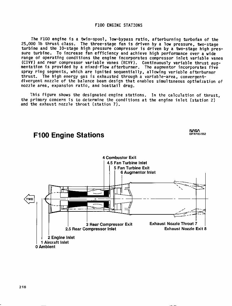
The FlOO engine is a twin-spool, low-bypass ratio, afterburning turbofan of the 25,000 lb thrust class. The three-stage fan is driven by a low pressure, two-stage turbine and the lo-stage high pressure compressor is driven by a two-stage high pres- sure turbine. To increase fan efficiency and achieve high performance over a wide range of operating conditions the engine incorporates compressor inlet variable vanes (CIVV) and rear compressor variable vanes (RCVV). mentation is provided by a mixed-flow afterburner.
Continuously variable thrust aug- The augmentor incorporates five
spray ring segments, which are ignited sequentially, allowing variable afterburner thrust. The high energy gas is exhausted through a variable-area, convergent-
ltaneous optimization of divergent nozzle of the balance beam design that enables simu nozzle area, expansion ratio, and boattail drag.
This figure shows the designated engine stations. In the the primary concern is to determine the conditions at the eng and the exhaust nozzle throat (station 7).
calculation of thrust, ine inlet (station 2)
FIOO Engine Stations
a FWD
DFRF83.552
4 Combustor Exit 4.5 Fan Turbine Inlet
3 RearCompressor Exit 2.5 Rear Compressor Inlet
2 Engine Inlet I 1 Aircraft Inlet 0 Ambient
Exhaust Nozzle Exit 8
218
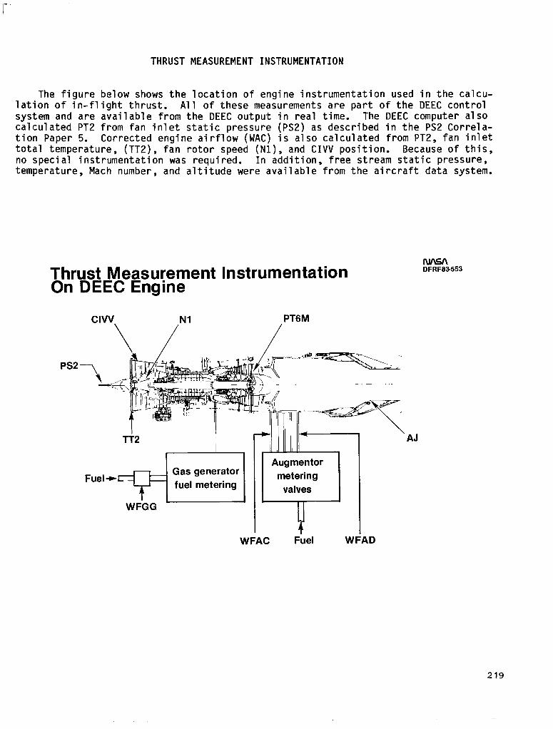
THRUST MEASUREMENT INSTRUMENTATION
The figure below shows the location of engine instrumentation used in the calcu- lation of in-flight thrust. All of these measurements are part of the DEEC control system and are available from the DEEC output in real time. The DEEC computer also calculated PT2 from fan inlet static pressure (PS2) as described in the PS2 Correla- tion Paper 5. Corrected engine airflow (WAC) is also calculated from PT2, fan inlet total temperature, (TT2), fan rotor speed (Nl), and CIVV position. Because of this, no special instrumentation was required. In addition, free stream static pressure, temperature, Mach number, and altitude were available from the aircraft data system.
Thrust Measurement Instrumentation On DEEC Engine
CIW Nl
\ /
PTGM
/
PS2 71
Tf2
DFRFB3553
AJ
WFAC F;el WFAD
219

REAL-TIME THRUST CALCULATION
The software used to calculate in-flight thrust real time is a modified version of the engine manufacturers' Fortran IV data reduction routine for determining in- flight performance, and was intended for off-line analysis. The in-flight thrust deck uses gas generator methods in which a combination of measured parameters and math models of engine characteristics are used to calculate gross thrust. Empirical data comes from sea level static tests and altitude facility tests. Two gas genera- tor models are used; one based on pressure and nozzle throat area, the other on temperature and the gas flow rate.
Real Time In-flight Thrust Calculation Thrust
DFRF93.559
Airframe
M
7 PO PTINF lT0 ALT
-D
Gas Generator Method
‘WG.5 TT6 ’ WFT PTGM
I Afterburner duct total pressure
AJ
loss. PT7: GAMA, TT7 and WG7 calculation: and afterburner
fuel+aair ratio 1 GAMA GAMA Fuel-to& PT7 PT7 ratio of
WG7 lT7 l-r6 augmentor
PO Ideal FG Nozzle analysis
4 +
V Calculated FG
1 c
Ram drag Calculated FN
1 FIOO Engine
4 I
I ,+ Measurements
I Nl PS2 WFGG
’ AJ PTGM WFAC CIVV lT2 WFAD
220

MODIFICATIONS MADE TO RUN REAL TIME
To increase the efficiency of the program and to meet real-time compatibility requirements, the modifications shown below were made to the original program. These changes were made primarily to increase the speed of data reduction; no changes were made to the method of calculation. Input and output was accomplished by use of a common block statement which allowed instantaneous updating of all parameters.
Modifications Made to Run Real Time DFRFB3-556
Total airflow calculation logic including 5 subroutines were removed because of its availability from the DEEC
Uncertainty logic was changed to allow the user control over the rate the uncertainty analysis is made
The original output format was deleted and the number of output parameters was reduced to 10
Input data from the airframe and engine/DEEC was accessed instantaneously from the main ground computer program
221
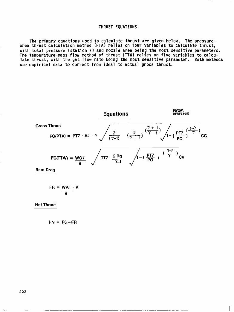
THRUST EQUATIONS
The primary equations used to calculate thrust are given below. The pressure- area thrust calculation method (PTA) relies on four variables to calculate thrust, with total pressure (station 7) and nozzle area being the most sensitive parameters. The temperature-mass flow method of thrust (TTW) relies on five variables to calcu- late thrust, with the gas flow rate being the most sensitive parameter. Both methods use empirical data to correct from ideal to actual gross thrust.
Equations DFRF83.555
Gross Thrust
FG(PTA) = PT~.AJ.~/-~&~cG
FG(TTW) = WG7
Ram Drag
FR = WAT .V 9
Net Thrust
FN = FG-FR
222
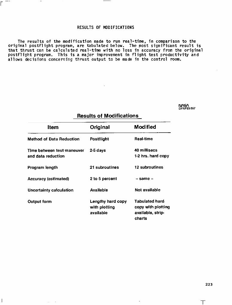
RESULTS OF MODIFICATIONS
The results of the modification made to run real-time, in comparison to the original postflight program, are tabulated below. The most significant result is that thrust can be calculated real-time with no loss in accuracy from the original postflight program. This is a major improvement in flight test productivity and allows decisions concerning thrust output to be made in the control room.
DFRF83.557
Results of Modifications
Item Modified
Method of Data Reduction Postflight
Time between test maneuver 2-5 days and data reduction
Program length
Accuracy (estimated)
Uncertainty calculation
Output form
21 subroutines
2 to 5 percent
Available
Lengthy hard copy with plotting available
Real-time
40 millisecs I-2 hrs. hard copy
12 subroutines
-- same --
Not available
Tabulated hard copy with plotting available, strip charts
223
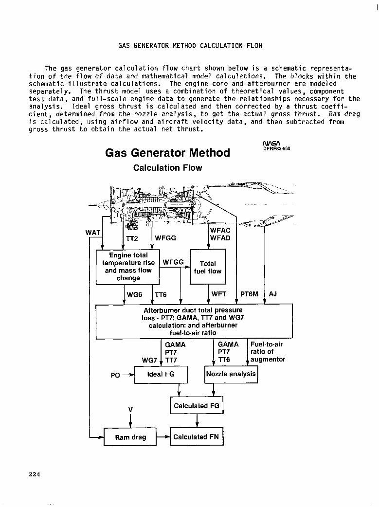
GAS GENERATOR METHOD CALCULATION FLOW
The gas generator calculation flow chart shown below is a schematic representa- tion of the flow of data and mathematical model calculations. The blocks within the schematic illustrate calculations. The engine core and afterburner are modeled separately. The thrust model uses a combination of theoretical values, component test data, and full-scale engine data to generate the relationships necessary for the analysis. Ideal gross thrust is calculated and then corrected by a thrust coeffi- cient, determined from the nozzle analysis, to get the actual gross thrust. Ram drag is calculated, using airflow and aircraft velocity data, and then subtracted from gross thrust to obtain the actual net thrust.
Gas Generator Method Calculation Flow
WG6 TT6 I IWFT PTGM
Afterburner duct total pressure loss - PT7;.GAMA, TT7 and WG7
calculation: and afterburner fuel-to-air ratio
DFRF83-560
AJ
,Fuel-to-air ratio of
PO Ideal FG
+’
Nozzle analysis
4
V Calculated FG
I I
Ram drag --) Calculated FN
224

REAL-TIME DATA SYSTEM
The real-time data system, used during DEEC testing, is shown below. Data from the engine and airframe instrumentation is captured and then telemetered to the ground station, where the raw data is stored on digital tape. This raw data is also supplied to the real-time computer for engineering unit conversions and calculations. The computer then supplies the output to the appropriate device. Thrust, ram drag, and specific fuel consumption are displayed on the cathode ray tube (CRT).
DFRF83653a
F-15 DEEC Real-Time Data System FlOOengine
4 f Receiver/ demultiplex
Computer
225
I II I I I I

NEAR REAL-TIME THRUST TIME HISTORY
To aid in the performance analysis during a test flight, hard copy plots such as the one below are available shortly after any maneuvers. Excellent agreement between the two calculated thrust parameters is shown for the last half of the test. The discrepancy between the calculated thrust values for the first part of the test could have been due to nonstabilized engine conditions. This is an example in which the real-time thrust computation data could be used in the flight control room to repeat the first part of the acceleration run, in an attempt to obtain improved agreement between the two methods.
Near Real-Time Thrust Time History DFRF63.562
Mil Power Accel 30,000 ft
10 x 103 Thrust-Time History
8
t
-----PTA Method - llW Method
Net 6- Thrust
LB
0, I I I
0 6 12 18 24 30 36 42 48 64 60
Time(sec)
226
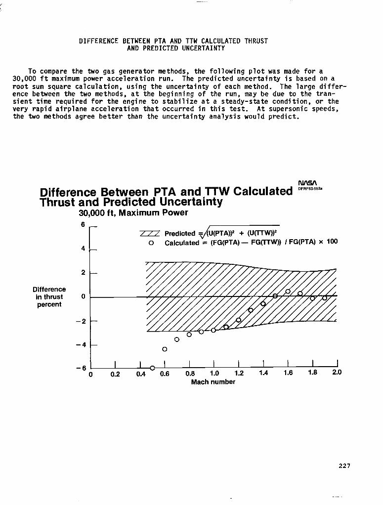
DIFFERENCE BETWEEN PTA AND TTW CALCULATED THRUST AND PREDICTED UNCERTAINTY
To compare the two gas generator methods, the following plot was made for a 30,000 ft maximum power acceleration run. The predicted uncertainty is based on a root sum square calculation, using the uncertainty of each method. The large differ- ence between the two methods, at the beginning of the run, may be due to the tran- sient time required for the engine to stabilize at a steady-state condition, or the very rapid airplane acceleration that occurred in this test. At supersonic speeds, the two methods agree better than the uncertainty analysis would predict.
Difference Between PTA and TTW Calculated E3a Thrust and Predicted Uncertainty
30,000 ft, Maximum Power 6
c
/// Predicted (PTA))1 + (UVW)' 0 Calculated = (FG(PTA)- FG(TTW)) /FG(PTA) x 100
4
Difference in thrust percent
-6 I I 8 I I I I I I I I 0 0.2 0.4 0.6 0.8 1.0 1.2 1.4 1.6 1.8 2.0
Mach number
227
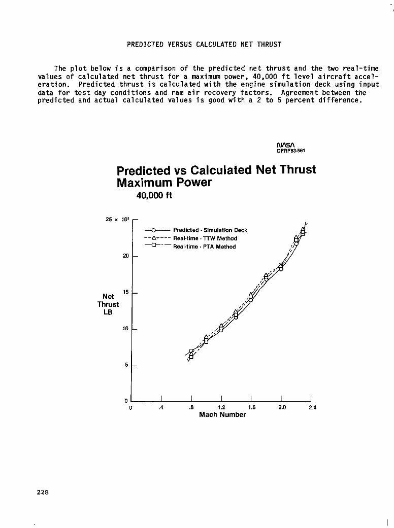
PREDICTED VERSUS CALCULATED NET THRUST
The plot below is a comparison of the predicted net thrust and the two real-time values of calculated net thrust for a maximum power, 40,000 ft level aircraft accel- eration. Predicted thrust is calculated with the engine simulation deck using input data for test day conditions and ram air recovery factors. Agreement between the predicted and actual calculated values is good with a 2 to 5 percent difference.
DFRF63.561
Predicted vs Calculated Net Thrust Maximum Power
40,000 ft
25 x 10’
20
Net l5 Thrust
LB
10
V Predicted - Simulation Deck --a---- Real-time. lTW Method --- Real-time . PTA Method
I I I 0 .4 .8 1.2 1.6 2.0 2.4
Mach Number
228
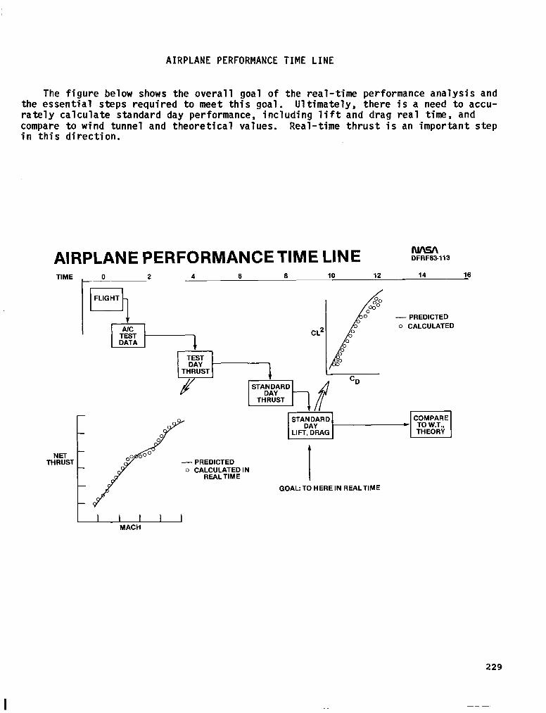
AIRPLANE PERFORMANCE TIME LINE
The figure below shows the overall goal of the real-time performance analysis and the essential steps required to meet this goal. Ultimately, there is a need to accu- rately calculate standard day performance, including lift and drag real time, and compare to wind tunnel and theoretical values. Real-time thrust is an important step in this direction.
AIRPLANE PERFORMANCETIME LINE TIME , 0 2 4 6
DFRF83113
- PREDICTED
CL2 o CALCULATED
T&kT - PREDICTED o CAbClJ&A;E; IN
GOAL: TO HERE IN REALTIME
MACH
229
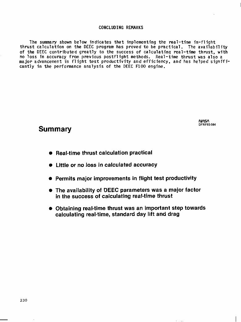
CONCLUDING REMARKS
The summary shown below indicates that implementing the real-time in-flight thrust calculation on the DEEC program has proved to be practical. The availability of the DEEC contributed greatly to the success of calculating real-time thrust, with no loss in accuracy from previous postflight methods. Real-time thrust was also a major advancement in flight test productivity and efficiency, and has helped signifi- cantly in the performance analysis of the DEEC FlOO engine.
DFRF63-564
Summary
l Real-time thrust calculation practical
l Little or no loss in calculated accuracy
0 Permits major improvements in flight test productivity
0 The availability of DEEC parameters was a major factor in the success of calculating real-time thrust
l Obtaining real-time thrust was an important step towards calculating real-time, standard day lift and drag
230