real-time implementation of a statcom
TRANSCRIPT

8/10/2019 Real-Time Implementation of a STATCOM
http://slidepdf.com/reader/full/real-time-implementation-of-a-statcom 1/8
Real-Time Implementation of a STATCOM on a
Wind Farm Equipped with Doubly Fed Induction
Generators
Wei Qiao1, Ganesh K. Venayagamoorthy2, and Ronald G. Harley1
1Intelligent Power Infrastructure Consortium
School of Electrical and Computer Engineering
Georgia Institute of Technology
Atlanta, GA 30332-0250 USA
E-mail: {weiqiao, rharley}@ece.gatech.edu
2Real-Time Power and Intelligent Systems Laboratory
Department of Electrical and Computer Engineering
University of Missouri-Rolla
Rolla, MO 65409-0249 USA
E-mail: [email protected]
Abstract —Voltage stability is a key issue to achieve theuninterrupted operation of wind farms equipped with doubly fedinduction generators (DFIGs) during grid faults. A Static
Synchronous Compensator (STATCOM) is applied to a powernetwork which includes a DFIG driven by a wind turbine, forsteady state voltage regulation and transient voltage stability
support. The control schemes of the DFIG rotor-side converter,grid-side converter and the STATCOM are suitably designed andcoordinated. The system is implemented in real-time on a Real-Time Digital Simulator (RTDS®). Results show that theSTATCOM improves the transient voltage stability and therefore
helps the wind turbine generator system to remain in serviceduring grid faults.
Keywords-doubly fed induction generator; real-timeimplementation; STATCOM; wind turbine
I. I NTRODUCTION
The worldwide concern about the environmental pollutionand a possible energy shortage has led to increasing interest intechnologies for generation of renewable electrical energy.Among various renewable energy sources, wind generation has
been the leading source in Europe and the United States.
With the recent progress in modern power electronics, theconcept of a variable-speed wind turbine (VSWT) equippedwith a doubly fed induction generator (DFIG) is receivingincreasing attention due to its advantages over other wind turbineconcepts [1]-[4]. In the DFIG concept, the induction generatoris grid-connected at the stator terminals as well as at the rotormains via a partially rated variable frequency AC/DC/ACconverter (VFC), which only needs to handle a fraction (25-
30%) of the total power to achieve full control of the generator.The VFC consists of a rotor-side converter (RSC) and a grid-sideconverter (GSC) connected back-to-back by a dc-link capacitor.
When connected to the grid and during a grid fault, theRSC of the DFIG may be blocked in order to protect it fromover-current in the rotor circuit [1], [3]-[4]. The wind turbine
trips shortly after the converter has blocked and automaticallyre-connects to the power network a few seconds after the faulthas cleared. In [1], the author proposed an uninterrupted
operation feature of a DFIG wind turbine during grid faults. Inthis feature, the rotor circuit is short-circuited through a crow-
bar circuit (an external resistor); the generator becomes aconventional induction generator and starts to absorb reactive
power. The wind turbine continues its operation to producesome active power and the GSC can be set to control thereactive power and voltage. The pitch angle controller might beactivated to prevent the wind turbine from fatal over-speeding.When the fault has cleared and when the voltage and thefrequency in the power network have been re-established, theRSC will re-start and the wind turbine will return to normaloperation. However, in the case of a weak power network andduring a grid fault, the GSC cannot provide sufficient reactive
power and voltage support due to its small power capacity, and
there can be a risk of voltage instability. As a result, the RSCwill not re-start and the wind turbine will be disconnected fromthe network. Therefore, voltage stability is the crucial issue inmaintaining uninterrupted operation of wind turbines equippedwith DFIGs [1]. With the rapid increase in penetration of wind
power in power systems, tripping of many wind turbines in alarge wind farm during grid faults may begin to influence theoverall power system stability. It has been reported recently thatincorporation of wind farms into the East Danish power systemcould cause severe voltage recovery problem following a three-
phase fault on the network [5]. This problem of voltage instabilitycan be solved by using dynamic reactive power compensation.
Shunt Flexible AC Transmission System (FACTS) devices,such as the Static Var Compensator (SVC) and the StaticSynchronous Compensator (STATCOM), have been widelyused to provide high performance steady state and transientvoltage control at the Point of Common Coupling (PCC) [6].The applications of a SVC or a STATCOM to fixed-speedwind turbines equipped with induction generators have beenreported in [7] for steady state voltage regulation, and in [1] forshort-term transient voltage stability.
This paper investigates the application of a STATCOM tohelp with the uninterrupted operation of a VSWT equipped with
This work was supported in part by the National Science Foundation,
Washington, DC, USA, under grant ECS 0524183 and the Duke Power
Company, Charlotte, North Carolina, USA
1-4244-0365-0/06/$20.00 (c) 2006 IEEE 73
8/10/2019 Real-Time Implementation of a STATCOM
http://slidepdf.com/reader/full/real-time-implementation-of-a-statcom 2/8
a DFIG during grid faults. The STATCOM is shunt connectedat the bus where the wind turbine is connected to the powernetwork in order to provide steady state voltage regulation andimprove the short-term transient voltage stability. The systemis implemented on a Real-Time Digital Simulator (RTDS
®).
The power network model, the DFIG model with its controlscheme, the wind turbine model, and the STATCOM modelwith its control scheme are presented in the next four sections,respectively. The real-time implementation results show thatwith suitably designed STATCOM and DFIG control schemes,the DFIG can ride through grid faults to remain in service. Onthe other hand, without the STATCOM to provide local dynamicreactive power support, the voltage cannot recover and thereforethe wind turbine has to be tripped from the power network.
II. POWER NETWORK MODEL
In a real power system, a large wind farm generally consistsof hundreds of individual wind turbines. A STATCOM can be
placed at the PCC between the wind farm and the power network.It has been reported in [1] that with well-tuned converters, thereis no mutual interaction between wind turbines in a wind farm,independently from the conditions of the power grid. Therefore
in this paper, only one wind turbine is used to represent thewind farm.
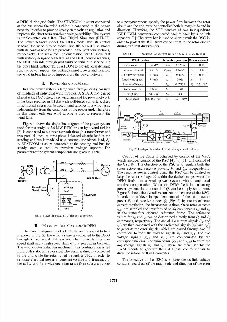
Figure 1 shows the single-line diagram of the power systemused for this study. A 3.6 MW DFIG driven by a wind turbine[8] is connected to a power network through a transformer andtwo parallel lines. A three-phase balanced electric load at thesending end bus is modeled as a constant impedance load, Z L.A STATCOM is shunt connected at the sending end bus forsteady state as well as transient voltage support. The
parameters of the system components are given in Table I.
DFIG
Infinite Bus
Line 2
Line 1 1l r
2l r
1l x
2l x
Three-PhaseElectric Load
WindTurbine
STATCOM
VSI
dcV
System
vt
it
vi
ii
Z L
T1
T2
QC
Fig. 1. Single-line diagram of the power network.
III. MODELING A ND CONTROL OF DFIGThe basic configuration of a DFIG driven by a wind turbine
is shown in Fig. 2. The wind turbine is connected to the DFIGthrough a mechanical shaft system, which consists of a low-speed shaft and a high-speed shaft with a gearbox in between.The wound-rotor induction machine in this configuration is fedfrom both stator and rotor side. The stator is directly connectedto the grid while the rotor is fed through a VFC. In order to
produce electrical power at constant voltage and frequency tothe utility grid for a wide operating range from subsynchronous
to supersynchronous speeds, the power flow between the rotorcircuit and the grid must be controlled both in magnitude and indirection. Therefore, the VFC consists of two four-quadrantIGBT PWM converters connected back-to-back by a dc-linkcapacitor [9]. The crow-bar is used to short-circuit the RSC inorder to protect the RSC from over-current in the rotor circuitduring transient disturbances.
TABLE I. SYSTEM PARAMETERS (O N 3.6 MW, 4.16 K V BASES)
rabcv
rabci dcV
gabcv
gabci
sabci sabcv
g r
C
g L
g C
labci
f L
Fig. 2. Configuration of a DFIG driven by a wind turbine.
Control of the DFIG is achieved by control of the VFC,which includes control of the RSC [4], [9]-[11] and control ofthe GSC [9]. The objective of the RSC is to regulate both the
stator active and reactive powers, P s and Q s, independently.The reactive power control using the RSC can be applied tokeep the stator voltage V s within the desired range, when theDFIG feeds into a weak power system without any localreactive compensation. When the DFIG feeds into a strong
power system, the command of Q s can be simply set to zero.Figure 3 shows the overall vector control scheme of the RSC.In order to achieve independent control of the stator active
power P s and reactive power Q s (Fig. 2) by means of rotorcurrent regulation, the instantaneous three-phase rotor currentsirabc are sampled and transformed to dq components idr and iqr in the stator-flux oriented reference frame. The referencevalues for idr and iqr can be determined directly from Q s and P s commands, respectively. The actual d -q current signals (idr and
iqr ) are then compared with their reference signals (idr
*
and iqr
*
)to generate the error signals, which are passed through two PIcontrollers to form the voltage signals vdr 1 and vqr 1. The twovoltage signals (vdr 1 and vqr 1) are compensated by thecorresponding cross coupling terms (vdr 2 and vqr 2) to form thed -q voltage signals vdr and vqr . These are then used by thePWM module to generate the IGBT gate control signals todrive the rotor-side IGBT converter.
The objective of the GSC is to keep the dc-link voltageconstant regardless of the magnitude and direction of the rotor
Wind turbine Induction generator Power network
Rated capacity 3.6 MW P rated 3.6 MW r l 1 0.14
Cut-in wind speed 3.5 m/s V s,rated 4.16 kV xl 1 0.8
Cut-out wind speed 27 m/s r s 0.0079 r l 2 0.14
Rated wind speed 14 m/s r r 0.025 xl 2 0.8
Number of blades 3 Lls 0.07939 Z L 0.7+ j1.5
Rotor diameter 104 m Llr 0.40
Swept area 8495 m2 Lm 4.4
Rotor speed 8.5-15.3 rpm pf -0.9 ~ +0.9
74

8/10/2019 Real-Time Implementation of a STATCOM
http://slidepdf.com/reader/full/real-time-implementation-of-a-statcom 3/8
power [9]. In this paper, the GSC control scheme is also designedto regulate the reactive power, Q g , exchanged between the GSCand the grid. During normal operation, the GSC is consideredto be reactive neutral by setting Q g
* = 0. This consideration isreasonable because the VFC rating is only 25-30% of thegenerator rating and the VFC is primarily used to supply theactive power from the rotor to the power grid. However, thereactive power controllability of the GSC can be useful duringthe process of voltage re-establishment, after a grid fault has
been cleared and the RSC has been blocked. Figure 4 showsthe overall control scheme of the GSC. The actual signals ofthe dc-link voltage and the reactive power (V dc and Q g ) arecompared with their command values (V dc
* and Q g *) to form the
error signals, which are passed through the PI controllers togenerate the reference signals for the d -axis and q-axis currentcomponents (idg
* and iqg *), respectively. The instantaneous ac-
side three-phase currents of the GSC are sampled andtransformed into d -q current components idg and iqg by applyingthe synchronously rotating reference frame transformation. Theactual signals (idg and iqg ) are then compared with thecorresponding reference signals to form the error signals,which are passed through two PI controllers. The voltagesignals (vdg 1 and vqg 1) are compensated by the correspondingcross coupling terms to form the d -q voltage signals vdg and vqg .They are then used by the PWM module to generate the IGBTgate control signals to drive the grid-side IGBT converter.
∑
s P
∗
qr i∑
*
s P
qr i
∑
2qr v
1qr v qr
v
∑ ∑ ∑* sQ sQ
∗
dr i
dr i
1dr v
dr v
sabcv
sabci
∑
dcV
rabci
2dr v
sθ
s ρ s s
θ ρ −
Fig. 3. Overall control scheme of theRSC: vdr 2 = - sω sσ Lr iqr , vqr 2 = sω s(σ Lr idr + Lm
2ims/ L s).
∑ ∑ ∑
∑ ∑ ∑
*
g Q
gabci
∗
qg i
∗
dg i
g θ
dg g s i Lω
qg g s i Lω
sabcv
g θ
*
dcV
Fig. 4. Overall control scheme of the GSC.
IV. WIND TURBINE MODEL
The aerodynamic model of a wind turbine can becharacterized by the well-known C P - λ- β curves. C P is called
power coefficient, which is a function of both tip-speed-ratio λ and the blade pitch angle β . The tip-speed-ratio λ is defined by
wt v R /ω λ = (1)
where R is the blade length in m, ωt is the wind turbine rotorspeed in rad/s, and vw is the wind speed in m/s. The C P - λ- β curves depend on the blade design and are given by the windturbine manufacturer. Given the power coefficient C P , themechanical power extracted by the turbine from the wind, is
calculated by [1], [8]
),(3
21 β λ ρ P wr m C v A P = (2)
where ρ is the air density in kg/m3; Ar = π R2 is the area in m2 swept by the rotor blades.
At a specific wind speed, there is a unique value of ωt toachieve the maximum power coefficient C P and thereby extractthe maximum mechanical (wind) power. If the wind speed is
below the rated (maximum) value, the wind turbine operates inthe variable speed mode, and the rotational speed is adjusted(by means of active power control in the DFIG) such that themaximum value of C P is achieved. In this operating mode, thewind turbine pitch control is deactivated and the pitch angle β
is fixed at 0○. If the wind speed is above the rated value, therotor speed can no longer be controlled within the limits byincreasing the generated power, as this would lead tooverloading of the generator and/or the converter. In thissituation, the pitch control is activated to increase the windturbine pitch angle to reduce the mechanical power extractedfrom wind. Figure 5 shows the structure of the pitch anglecontroller [1], [8]. P t (= P s + P r ) is the total output active powerfrom the induction generator.
∑+
-
PI
ωr
*
r ω ∑
+
∑+
-
PI
P t
*
t P
+
∑ β *
+1T
1 s
β
- β
β max
β min(d β /dt )min
(d β /dt )max
Fig. 5. Wind turbine pitch angle controller
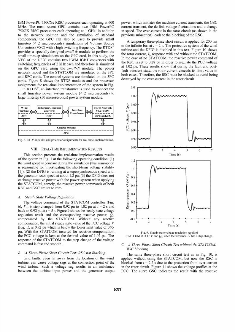
V. STATCOM MODEL
A STATCOM [6], [12], also known as an advanced staticVAR compensator, is a shunt connected FACTS device. Itgenerates a set of balanced three-phase sinusoidal voltages atthe fundamental frequency, with rapidly controllable amplitudeand phase angle. A typical application of a STATCOM is forvoltage support. In this paper, the STATCOM is modeled as aGTO PWM converter with a dc-link capacitor. The objective of
the STATCOM is to regulate the voltage at the PCC rapidly inthe desired range and keep its dc-link voltage constant. It canenhance the capability of the wind turbine to ride throughtransient disturbances in the grid. The overall control scheme ofthe STATCOM is shown in Fig. 6.
VI. U NINTERRUPTED OPERATION FEATURE OF THE WIND
TURBINE DURING GRID FAULTS
The idea behind this feature is that the wind turbine doesnot trip when the RSC has blocked during the grid fault.
75
8/10/2019 Real-Time Implementation of a STATCOM
http://slidepdf.com/reader/full/real-time-implementation-of-a-statcom 4/8
During the RSC blocking, the rotor circuit is short-circuited bya crow-bar, which is simply implemented by connecting anexternal resistor to each phase of the rotor circuit. The value ofthe external resistance is chosen as Rext = 20·r r , asrecommended in [13]. The wind turbine continues its operationwith the induction generator with a short-circuited rotor circuit.During such an operation condition, the controllability of theRSC is naturally lost and there is no longer any independentcontrol of active and reactive power in the DFIG. Thegenerator becomes a conventional induction generator, which
produces an amount of active power and starts to absorb anamount of reactive power. In order to prevent the wind turbinefrom over-speeding, the pitch angle controller can be activatedto keep the speed around the pre-defined value.
∑ ∑ ∑
∑ ∑ ∑
*dcV
dcV
*t V
∗
dvi
∗
qvi
dcV
Fig. 6. Overall control scheme of the STATCOM.
During the RSC blocking, the RSC control systemcontinues monitoring the rotor current, the terminal voltage, theactive and reactive powers and the generator rotor speed. Whenthe fault has cleared and when the terminal voltage and therotor current return back to their pre-defined ranges, the RSCstarts synchronization [1]. At synchronization, the RSC starts
switching and the external resistance is disconnected; the d -q components of the RSC voltage source (Fig. 3) are set to vdr =idr · Rext and vqr = iqr · Rext , which are used by the PWM moduleto generate the IGBT gate control signals to drive the IGBTconverter. When the synchronization seems to be complete, thecontrol system of the RSC switches to the regular controlsystem as shown in Fig. 3 and the RSC re-starts. When theRSC has re-started, the DFIG again has independent active andreactive power control and the wind turbine returns to normaloperation.
The advantages of this uninterrupted operation featureinclude: (1) the wind turbine continues supplying the active
power to the power network and therefore the demand forimmediate power reserves does not exist or it is reduced; (2)
the wind turbine can contribute to maintaining the frequency inthe power network during a transient state.
When the RSC is blocking, the GSC can be set to controlthe reactive power exchanged between the DFIG and the grid.This controllability of the RSC, however, is limited due to thesmall capacity of the converter. In the case of a weak powernetwork, there can be a risk of voltage instability initiated bythe grid fault. As a result, the RSC will not re-start and thewind turbine will be disconnected from the network. One
solution to this problem is to use the dynamic reactivecompensator – the STATCOM, to provide transient voltagesupport to help the RSC ride through grid faults. In addition,the STATCOM can also be used for steady state voltageregulation and power factor control of the DFIG.
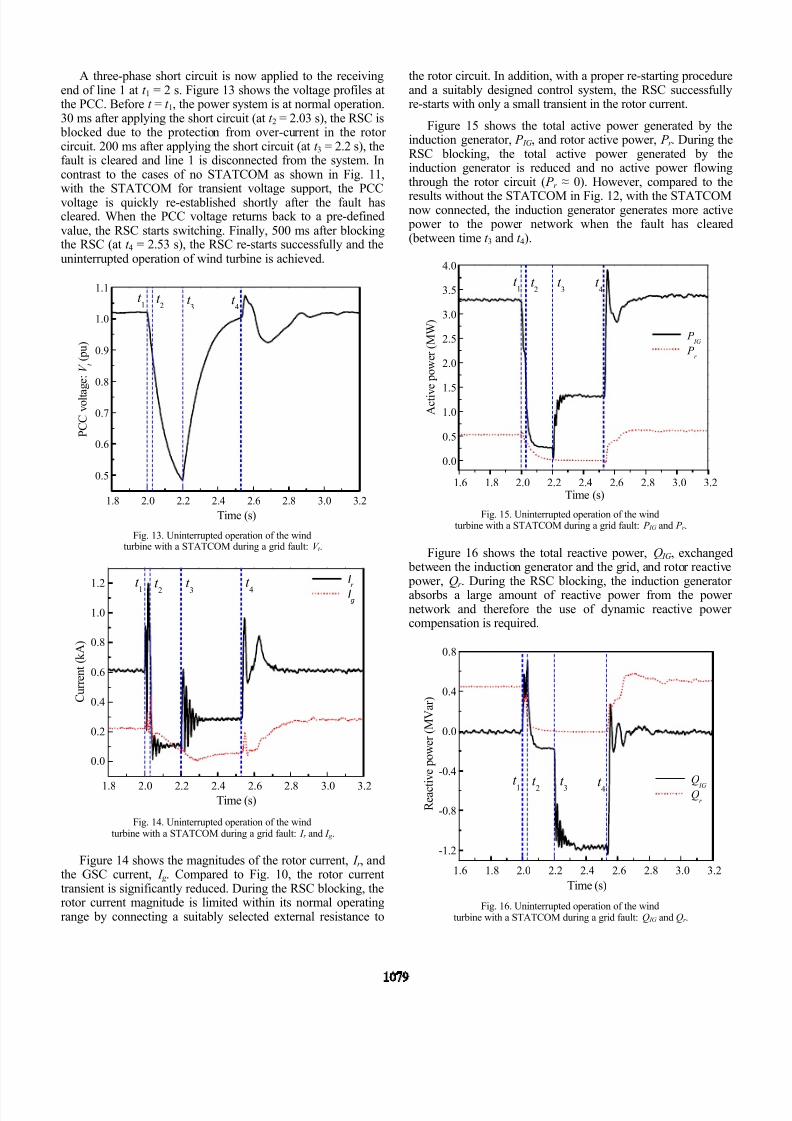
VII. R EAL-TIME IMPLEMENTATION SETUP
The RTDS® is a fully digital electromagnetic transient power
system simulator capable of continuous, sustained real-timeoperation [14]. That is, it can solve the power system equationsfast enough to continuously produce output conditions thatrealistically represent conditions in the real network. The RTDS® has been widely accepted as an ideal tool for the design,development and testing of power system protection and controlschemes. Because the solution is real-time, it can be connecteddirectly to power system control and protective relay components.
The RTDS® is a combination of advanced computer hardwareand comprehensive software as shown in Fig. 7. It has a custom
parallel processing hardware architecture assembled in modularunits called racks. Each rack contains both processing andcommunication modules. The mathematical computations for
individual power system components and for networkequations are performed using processor modules. The RTDS® uses a user friendly graphical interface – the RSCAD SoftwareSuite, as the user’s main interface with the RTDS hardware.The software is comprised of several modules designed toallow the user to easily perform all of the necessary steps to
prepare and run a simulation and to analyze simulation output.
Fig. 7. Real-time implementation setup using RTDS®
.
The RTDS® hardware has a number of different types of processor cards available including the Triple Processor Cards(3PC), the RISC Processor Card (RPC) and the Giga ProcessorCard (GPC). The 3PC contains three Analog DevicesADSP21062 (SHARC) processors each operating at 80 MHz.The 3PC is typically used to perform the computations requiredto model the user's power system and control systems with atypical time step of 50 microseconds. The RPC contains two
76
8/10/2019 Real-Time Implementation of a STATCOM
http://slidepdf.com/reader/full/real-time-implementation-of-a-statcom 5/8
IBM PowerPC 750CXe RISC processors each operating at 600MHz. The most recent GPC contains two IBM PowerPC750GX RISC processors each operating at 1 GHz. In additionto the network solution and the simulation of standardcomponents, the GPC can also be used to provide smalltimestep (< 2 microseconds) simulations of Voltage SourceConverters (VSC) with a high switching frequency. The RTDS
®
provides a specially designed small-dt module to perform thesmall timestep simulations on the GPC card. In this study, theVFC of the DFIG contains two PWM IGBT converters withswitching frequencies of 2 kHz each and therefore is simulatedon the GPC card using the small-dt module. The powernetwork model and the STATCOM are simulated on the 3PCand RPC cards. The control systems are simulated on the 3PCcards. Figure 8 shows the RTDS modules and the processorassignments for real-time implementation of the system in Fig.1. In RTDS®, an interface transformer is used to connect thesmall timestep power system module (< 2 microseconds) tolarge timestep (50 microseconds) power system module.
Fig. 8. RTDS modules and processor assignments for real-time implementation.
VIII. R EAL-TIME IMPLEMENTATION R ESULTS
This section presents the real-time implementation resultsof the system in Fig. 1 at the following operating condition: (1)the wind speed is constant during the simulation (this assumptionis reasonable for investigating the short-term voltage stability[1]); (2) the DFIG is running at a supersynchronous speed with
the generator rotor speed at about 1.2 pu; (3) the DFIG does notexchange reactive power with the power system when applyingthe STATCOM, namely, the reactive power commands of bothRSC and GSC are set to zero.
A. Steady State Voltage Regulation
The voltage command of the STATCOM controller (Fig.6), V t
*, is step changed from 0.92 pu to 1.02 pu at t = 2 s and back to 0.92 pu at t = 5 s. Figure 9 shows the steady state voltageregulation result and the corresponding reactive power, Qc,compensated by the STATCOM. Without any reactivecompensation, the initial steady state value of the PCC voltage V t (Fig. 1), is 0.92 pu which is below the lower limit value of 0.95
pu. With the STATCOM inserted for reactive compensation,the PCC voltage is kept at the desired value of 1.02 pu. Theresponse of the STATCOM to the step change of the voltagecommand is fast and smooth.
B.
A Three-Phase Short Circuit Test: RSC not Blocking
Grid faults, even far away from the location of the windturbine, can cause voltage sags at the connection point of thewind turbine. Such a voltage sag results in an imbalance
between the turbine input power and the generator output
power, which initiates the machine current transients, the GSCcurrent transient, the dc-link voltage fluctuations and a changein speed. The over-current in the rotor circuit (as shown in the
previous subsection) leads to the blocking of the RSC.
A temporary three-phase short circuit is applied for 200 msto the infinite bus at t = 2 s. The protective system of the windturbine and the DFIG is disabled in this test. Figure 10 showsthe rotor current, I r , response with and without the STATCOM.
In the case of no STATCOM, the reactive power command ofthe RSC is set to 0.28 pu in order to regulate the PCC voltageat 1.02 pu. These results show that during the fault and post-fault transient state, the rotor current exceeds its limit value in
both cases. Therefore, the RSC must be blocked to avoid beingdestroyed by the over-current in the rotor circuit.
1 2 3 4 5 6 70.90
0.92
0.94
0.96
0.98
1.00
1.02
1.04
P C C v o l t a g e : V
t ( p u )
Time (s)
1 2 3 4 5 6 7-0.2
0.0
0.2
0.4
0.6
0.8
1.0
1.2
R e a c t i v e p o w e r : Q
c ( M V a r
)
Time (s)
Fig. 9. Steady state voltage regulation result ofSTATCOM at PCC: V t and Qc, when the reference V t
* has a step-change.
C. A Three-Phase Short Circuit Test without the STATCOM:
RSC blocking
The same three-phase short circuit test as in Fig. 10, isapplied without using the STATCOM, but now the RSC is
blocked from t = 2.2 s due to the protection from over-currentin the rotor circuit. Figure 11 shows the voltage profiles at thePCC. The curve GSC indicates the result with the reactive
77

8/10/2019 Real-Time Implementation of a STATCOM
http://slidepdf.com/reader/full/real-time-implementation-of-a-statcom 6/8
compensation by the GSC (the reactive power command of theGSC is set to the maximum value 0.25 pu instead of 0) from 2s; and the curve NC indicates the result without any reactivecompensation from 2 s. In both cases GSC and NC, the reactive
power command of the RSC is set to 0.28 pu instead of 0 before applying the fault in order to regulate the PCC voltage at1.02 pu. The PCC voltage can not be re-established withoutany reactive compensation or only using the GSC. Therefore,the RSC cannot re-start and the wind turbine has to be trippedfrom the system.
1.8 2.0 2.2 2.4 2.6 2.80.0
0.2
0.4
0.6
0.8
1.0
1.2
1.4
1.6
1.8
2.0
2.2
Without STATCOM
R o t o r c u r r e n t : I r ( k A )
Time (s)
1.8 2.0 2.2 2.4 2.6 2.80.0
0.2
0.4
0.6
0.8
1.0
1.2
1.4
1.6
1.8
2.0
2.2
With STATCOM
R o t o r c u r r e n t : I r ( k A )
Time (s)
Fig. 10. RMS rotor current I r during a 200 msthree-phase short circuit at the infinite bus, RSC not blocking.
Figure 12 shows the total active power, P IG, generated by
the induction generator and the total reactive power, Q IG,exchanged between the induction generator and the grid.During the RSC blocking, the active power generated by theinduction generator reduces significantly for both the GSC andthe NC. After the fault has been cleared (at t = 2.2 s) but theRSC is still blocking, the induction generator absorbs somereactive power from the network. However, with the GSC
providing reactive compensation, the induction generatorgenerates more active power to the power network, and thereactive power absorbed by the induction generator is reduced.
1.8 2.0 2.2 2.4 2.6 2.8 3.0 3.20.3
0.4
0.5
0.6
0.7
0.8
0.9
1.0
1.1 GSC
NC
P C C
V o l t a g e : V
t ( p u )
Time (s)
Fig. 11. A 200 ms three-phase short circuit at theinfinite bus, RSC blocking without STATCOM: PCC voltage V t .
1.6 1.8 2.0 2.2 2.4 2.6 2.8 3.0 3.2
0.0
0.4
0.8
1.2
1.6
2.0
2.4
2.8
3.2 GSC
NC
A c t i v e p o w e r : P
I G
( M W )
Time (s)
1.6 1.8 2.0 2.2 2.4 2.6 2.8 3.0 3.2
-0.8
-0.4
0.0
0.4
0.8
1.2
1.6
GSC NC
R e a c t i v e p o w e r : Q
I G
( M V a r )
Time (s)
Fig. 12. A 200 ms three-phase short circuit at theinfinite bus, RSC blocking without STATCOM: P IG and Q IG.
D. Uninterrupted Operation of the Wind Turbine with the
STATCOM
The STATCOM is now used to help achieve theuninterrupted operation of the wind turbine. During the entiretest, the reactive power command of the GSC is set to Q g
* = 0.
78
8/10/2019 Real-Time Implementation of a STATCOM
http://slidepdf.com/reader/full/real-time-implementation-of-a-statcom 7/8
A three-phase short circuit is now applied to the receivingend of line 1 at t 1 = 2 s. Figure 13 shows the voltage profiles atthe PCC. Before t = t 1, the power system is at normal operation.30 ms after applying the short circuit (at t 2 = 2.03 s), the RSC is
blocked due to the protection from over-current in the rotorcircuit. 200 ms after applying the short circuit (at t 3 = 2.2 s), thefault is cleared and line 1 is disconnected from the system. Incontrast to the cases of no STATCOM as shown in Fig. 11,with the STATCOM for transient voltage support, the PCCvoltage is quickly re-established shortly after the fault hascleared. When the PCC voltage returns back to a pre-definedvalue, the RSC starts switching. Finally, 500 ms after blockingthe RSC (at t 4 = 2.53 s), the RSC re-starts successfully and theuninterrupted operation of wind turbine is achieved.
1.8 2.0 2.2 2.4 2.6 2.8 3.0 3.2
0.5
0.6
0.7
0.8
0.9
1.0
1.1
t 4
t 3
t 2
t 1
P C C v o l t a
g e : V
t ( p u )
Time (s)
Fig. 13. Uninterrupted operation of the windturbine with a STATCOM during a grid fault: V t .
1.8 2.0 2.2 2.4 2.6 2.8 3.0 3.2
0.0
0.2
0.4
0.6
0.8
1.0
1.2t 4t 3t 2t 1
I r
I g
C u r r e n t ( k A )
Time (s)
Fig. 14. Uninterrupted operation of the windturbine with a STATCOM during a grid fault: I r and I g .
Figure 14 shows the magnitudes of the rotor current, I r , andthe GSC current, I g . Compared to Fig. 10, the rotor currenttransient is significantly reduced. During the RSC blocking, therotor current magnitude is limited within its normal operatingrange by connecting a suitably selected external resistance to
the rotor circuit. In addition, with a proper re-starting procedureand a suitably designed control system, the RSC successfullyre-starts with only a small transient in the rotor current.
Figure 15 shows the total active power generated by theinduction generator, P IG, and rotor active power, P r . During theRSC blocking, the total active power generated by theinduction generator is reduced and no active power flowingthrough the rotor circuit ( P r ≈ 0). However, compared to the
results without the STATCOM in Fig. 12, with the STATCOMnow connected, the induction generator generates more active
power to the power network when the fault has cleared(between time t 3 and t 4).
0.0
0.5
1.0
1.5
2.0
2.5
3.0
3.5
4.0
t 4
t 3
t 2
t 1
P IG
P r
A c t i v
e p o w e r ( M W )
Time (s)1.6 1.8 2.0 2.2 2.4 2.6 2.8 3.0 3.2
Fig. 15. Uninterrupted operation of the windturbine with a STATCOM during a grid fault: P IG and P r .
Figure 16 shows the total reactive power, Q IG, exchanged between the induction generator and the grid, and rotor reactive power, Qr . During the RSC blocking, the induction generatorabsorbs a large amount of reactive power from the powernetwork and therefore the use of dynamic reactive powercompensation is required.
1.6 1.8 2.0 2.2 2.4 2.6 2.8 3.0 3.2
-1.2
-0.8
-0.4
0.0
0.4
0.8
t 4t 3t 2t 1 Q
IG Q
r
R e a c t i v e p o w e r ( M V a r )
Time (s)
Fig. 16. Uninterrupted operation of the windturbine with a STATCOM during a grid fault: Q IG and Qr .
79
8/10/2019 Real-Time Implementation of a STATCOM
http://slidepdf.com/reader/full/real-time-implementation-of-a-statcom 8/8
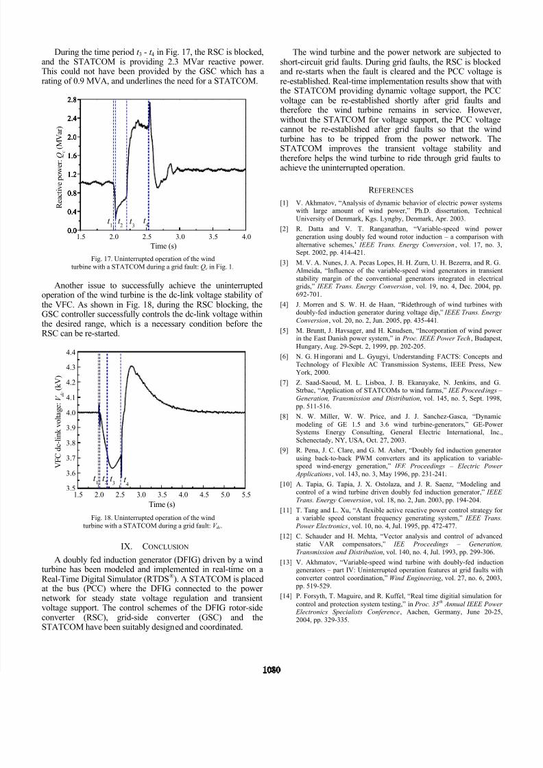
During the time period t 3 - t 4 in Fig. 17, the RSC is blocked,and the STATCOM is providing 2.3 MVar reactive power.This could not have been provided by the GSC which has arating of 0.9 MVA, and underlines the need for a STATCOM.
1.5 2.0 2.5 3.0 3.5 4.0
t 4
t 3
t 2
t 1
R e a c t i v e p o w e r : Q
c ( M V a
r )
Time (s)
0.0
0.4
0.8
1.2
1.6
2.0
2.4
2.8
0.0
0.4
0.8
1.2
1.6
2.0
2.4
2.8
0.0
0.4
0.8
1.2
1.6
2.0
2.4
2.8
0.0
0.4
0.8
1.2
1.6
2.0
2.4
2.8
Fig. 17. Uninterrupted operation of the wind
turbine with a STATCOM during a grid fault: Qc in Fig. 1.
Another issue to successfully achieve the uninterruptedoperation of the wind turbine is the dc-link voltage stability ofthe VFC. As shown in Fig. 18, during the RSC blocking, theGSC controller successfully controls the dc-link voltage withinthe desired range, which is a necessary condition before theRSC can be re-started.
1.5 2.0 2.5 3.0 3.5 4.0 4.5 5.0 5.53.5
3.6
3.7
3.8
3.9
4.0
4.1
4.2
4.3
4.4
t 4
t 3
t 2
t 1
V F C d c - l i n k v o l t a g e :
V d c
( k V )
Time (s)
Fig. 18. Uninterrupted operation of the windturbine with a STATCOM during a grid fault: V dc.
IX.
CONCLUSION
A doubly fed induction generator (DFIG) driven by a windturbine has been modeled and implemented in real-time on aReal-Time Digital Simulator (RTDS
®). A STATCOM is placed
at the bus (PCC) where the DFIG connected to the powernetwork for steady state voltage regulation and transientvoltage support. The control schemes of the DFIG rotor-sideconverter (RSC), grid-side converter (GSC) and theSTATCOM have been suitably designed and coordinated.
The wind turbine and the power network are subjected toshort-circuit grid faults. During grid faults, the RSC is blockedand re-starts when the fault is cleared and the PCC voltage isre-established. Real-time implementation results show that withthe STATCOM providing dynamic voltage support, the PCCvoltage can be re-established shortly after grid faults andtherefore the wind turbine remains in service. However,without the STATCOM for voltage support, the PCC voltagecannot be re-established after grid faults so that the windturbine has to be tripped from the power network. TheSTATCOM improves the transient voltage stability andtherefore helps the wind turbine to ride through grid faults toachieve the uninterrupted operation.
R EFERENCES
[1]
V. Akhmatov, “Analysis of dynamic behavior of electric power systemswith large amount of wind power,” Ph.D. dissertation, Technical
University of Denmark, Kgs. Lyngby, Denmark, Apr. 2003.
[2]
R. Datta and V. T. Ranganathan, “Variable-speed wind powergeneration using doubly fed wound rotor induction – a comparison with
alternative schemes,’ IEEE Trans. Energy Conversion , vol. 17, no. 3,Sept. 2002, pp. 414-421.
[3]
M. V. A. Nunes, J. A. Pecas Lopes, H. H. Zurn, U. H. Bezerra, and R. G.
Almeida, “Influence of the variable-speed wind generators in transientstability margin of the conventional generators integrated in electricalgrids,” IEEE Trans. Energy Conversion, vol. 19, no. 4, Dec. 2004, pp.
692-701.
[4]
J. Morren and S. W. H. de Haan, “Ridethrough of wind turbines withdoubly-fed induction generator during voltage dip,” IEEE Trans. Energy
Conversion , vol. 20, no. 2, Jun. 2005, pp. 435-441.
[5]
M. Bruntt, J. Havsager, and H. Knudsen, “Incorporation of wind powerin the East Danish power system,” in Proc. IEEE Power Tech, Budapest,
Hungary, Aug. 29-Sept. 2, 1999, pp. 202-205.
[6]
N. G. H ingorani and L. Gyugyi, Understanding FACTS: Concepts andTechnology of Flexible AC Transmission Systems, IEEE Press, New
York, 2000.
[7]
Z. Saad-Saoud, M. L. Lisboa, J. B. Ekanayake, N. Jenkins, and G.Strbac, “Application of STATCOMs to wind farms,” IEE Proceedings –
Generation, Transmission and Distribution, vol. 145, no. 5, Sept. 1998,
pp. 511-516.
[8]
N. W. Miller, W. W. Price, and J. J. Sanchez-Gasca, “Dynamic
modeling of GE 1.5 and 3.6 wind turbine-generators,” GE-PowerSystems Energy Consulting, General Electric International, Inc.,
Schenectady, NY, USA, Oct. 27, 2003.
[9]
R. Pena, J. C. Clare, and G. M. Asher, “Doubly fed induction generator
using back-to-back PWM converters and its application to variable-speed wind-energy generation,” IEE Proceedings – Electric Power
Applications , vol. 143, no. 3, May 1996, pp. 231-241.
[10]
A. Tapia, G. Tapia, J. X. Ostolaza, and J. R. Saenz, “Modeling andcontrol of a wind turbine driven doubly fed induction generator,” IEEE
Trans. Energy Conversion, vol. 18, no. 2, Jun. 2003, pp. 194-204.
[11]
T. Tang and L. Xu, “A flexible active reactive power control strategy fora variable speed constant frequency generating system,” IEEE Trans.
Power Electronics, vol. 10, no. 4, Jul. 1995, pp. 472-477.
[12]
C. Schauder and H. Mehta, “Vector analysis and control of advancedstatic VAR compensators,” IEE Proceedings – Generation,
Transmission and Distribution, vol. 140, no. 4, Jul. 1993, pp. 299-306.
[13]
V. Akhmatov, “Variable-speed wind turbine with doubly-fed inductiongenerators – part IV: Uninterrupted operation features at grid faults with
converter control coordination,” Wind Engineering , vol. 27, no. 6, 2003, pp. 519-529.
[14]
P. Forsyth, T. Maguire, and R. Kuffel, “Real time digitial simulation for
control and protection system testing,” in Proc. 35th Annual IEEE Power Electronics Specialists Conference , Aachen, Germany, June 20-25,
2004, pp. 329-335.
8