real-time bandwidth prediction and rate adaptation...
TRANSCRIPT
Real-time Bandwidth Prediction and Rate Adaptation forVideo Calls over Cellular Networks
Eymen [email protected]
Yong [email protected]
Department of Electrical and Computer EngineeringNYU Tandon School of Engineering, Brooklyn, NY
Yongfang [email protected]
ChenChen [email protected]
Jing [email protected]
Tencent Co. Ltd.Shenzhen, China, 518057
ABSTRACTWe study interactive video calls between two users, whereat least one of the users is connected over a cellular net-work. It is known that cellular links present highly-varyingnetwork bandwidth and packet delays. If the sending rateof the video call exceeds the available bandwidth, the videoframes may be excessively delayed, destroying the interac-tivity of the video call. In this paper, we present Rebera,a cross-layer design of proactive congestion control, videoencoding and rate adaptation, to maximize the video trans-mission rate while keeping the one-way frame delays suffi-ciently low. Rebera actively measures the available band-width in real-time by employing the video frames as packettrains. Using an online linear adaptive filter, Rebera makesa history-based prediction of the future capacity, and deter-mines a bit budget for the video rate adaptation. Reberauses the hierarchical-P video encoding structure to provideerror resilience and to ease rate adaptation, while maintain-ing low encoding complexity and delay. Furthermore, Re-bera decides in real time whether to send or discard an en-coded frame, according to the budget, thereby preventingself-congestion and minimizing the packet delays. Our ex-periments with real cellular link traces demonstrate Reberacan, on average, deliver higher bandwidth utilization andshorter packet delays than Apple’s FaceTime.
CCS Concepts•Networks → Cross-layer protocols; Network experi-mentation; Network measurement; Mobile networks;
Keywordsreal-time; cross-layer; forecasting; hierarchical-p
Permission to make digital or hard copies of all or part of this work for personal orclassroom use is granted without fee provided that copies are not made or distributedfor profit or commercial advantage and that copies bear this notice and the full cita-tion on the first page. Copyrights for components of this work owned by others thanACM must be honored. Abstracting with credit is permitted. To copy otherwise, or re-publish, to post on servers or to redistribute to lists, requires prior specific permissionand/or a fee. Request permissions from [email protected].
MMSys’16, May 10-13, 2016, Klagenfurt, Austriac© 2016 ACM. ISBN 978-1-4503-4297-1/16/05. . . $15.00
DOI: http://dx.doi.org/10.1145/2910017.2910608
1. INTRODUCTIONAdvances in networking and video encoding technologies
in the last decade have made the real-time video delivery ap-plications, including video calls and conferencing [17][9][3],an integral part of our lives. Despite their popularity inwired and Wi-Fi networks, real-time video applications havenot found much use over cellular networks. The fundamentalchallenge of delivering real-time video over cellular networksis to simultaneously achieve high-rate and low-delay videotransmission on highly volatile cellular links with rapidly-changing available bandwidth (ABW), packet delay and loss.On a cellular link, increasing the video sending rate beyondwhat is made available by the PHY and MAC layers leads toself-congestion, and intolerable packet delays, hence framedelays. Excessively delayed frames will have to be treatedas lost. On the other hand, a conservative sending rateclearly leads to the under-utilization of the cellular channeland consequently a lower quality than what is possible.
The tight design space calls for a joint application andtransport cross-layer design, involving real-time video en-coding, bitrate control, sending rate adjustment, and errorcontrol. Ideally, the transmitted video rate should closelytrack the ABW on the cellular links. However, traditionalreactive congestion control algorithms [30, 2], which adjustthe sending rate through packet loss and/or packet delay in-formation, are too slow to adapt to the changes in the ABW,leading to either bandwidth under-utilization or significantpacket delays [27]. It is more preferable to design proactivecongestion control algorithms that calculate the sending ratebased on cellular link ABW forecasts. Meanwhile, for videoadaptation, video encoder can adjust various video encod-ing parameters, so that the resulting video bitrate matchesthe target sending rate determined by the congestion controlalgorithm. However, accurate rate control is very challeng-ing for low-delay encoding, and significant rate mismatch isoften still present with the state-of-the-art video encoders.In addition, what makes the problem even more challengingis that the lost and late packets can render not only theircorresponding frames, but also other frames non-decodableat the receiver. The encoder and the transport layer shouldbe designed to be error resilient so that lost and late packetshave minimal impact on the decoded video.
In this study, we propose a new real-time video delivery

system, Rebera, designed for cellular networks, where we aimto maximize the sending rate of the video source and error re-silience, while keeping the one-way frame delays sufficientlysmall. Our system consists of a proactive congestion con-troller, a temporal layered encoder, and a dynamic frameselection module. Our proactive congestion controller usesthe video frames themselves to actively measure the currentABW in real-time, and then employs the well-known linearadaptive filtering methods [11] to predict the future capacity,based on the past and present capacity measurements. Forerror resilience, we resort to layered encoding, which enablesunequal error protection (UEP). However spatial and qualitylayering incurs significant encoding complexity and codingefficiency loss, making them unattractive for practical de-ployment. Thus we consider only temporal layering, whichprovides a certain level of error resilience even without usingexplicit UEP. To minimize the delays for real-time delivery,we use hierarchical-P (hierP) coding structure for temporallayering. To address the rate control inaccuracy of the en-coder, we propose a dynamic frame selection algorithm forhierarchical-P, where the goal is to select in real-time whichencoded frames to send, subject to a budget determinedby the predicted capacity value. Our frame selection algo-rithm takes into account quality implications of the layers,decoding dependencies between the frames, and the smooth-ness of frame inter-arrivals to maximize the delivered videoquality under the said budget. We have implemented thecomplete system, called “Rebera” for real-time bandwidthestimation and rate adaptation, to evaluate its performanceand compare it with Apple’s FaceTime video call applica-tion. Our implementation relies on an open source real-timeH.264 video encoder [24], which we have modified to producea hierarchical-P stream. As a result, we can directly controlthe encoded video rate according to the measured capac-ity. Thanks to the combination of all these components wehave mentioned, Rebera is able to achieve higher bandwidthutilization and lower frame delays than FaceTime. In thisstudy, we do not consider UEP among the temporal layersand the error resilience aspect of the system. These will beinvestigated in future studies.
2. RELATED WORKRate adaptation is a key problem for video transmission
over best-effort networks. Most of the previous studies focuson one-way streaming of live or recorded video, where a fewseconds of video buffering at the receiver can be tolerated.Due to buffering, a temporary mismatch between the videorate and the ABW does not directly impact the video play-back, as long as the buffer does not drain out. The recentindustry trend here is Dynamic Adaptive Streaming overHTTP (DASH) [20]. Various rate adaptation algorithmshave recently been proposed [6, 22, 13, 29], and some of themwere specifically designed for wireless networks, e.g. [19, 23].
To the contrary, video call involves two-way real-time videostreaming. To facilitate live interaction, video call does nothave the luxury of seconds of video buffering. Consequently,mismatch between the selected video rate and the ABWwill directly translate into quality degradation of video play-back, such as long video frame delays, delay jitters and videofreezes. Thus, for a video call, real-time bandwidth estima-tion and video rate adaptation are more challenging, com-pared with one-way video streaming.
Sending rate determination, or congestion control, has
been an active area of research for decades. Window-basedcongestion control algorithms are the dominant form of con-gestion control on the Internet, which reactively adjust thewindow size, and hence the sending rate according to acongestion signal. TCP variants such as Tahoe and NewReno [14] use packet losses, while Vegas [5], FAST [26] andCompound [21] react to packet round trip times. However,the additive-increase multiplicative-decrease (AIMD) prob-ing method used in TCP, along with the retransmission ofevery single lost packet in these protocols renders them lessdesirable for interactive video calls. TFRC [8] and TCPCubic [10] control the sending rate with smaller variations,however, their delay performances deteriorate in the faceof fast ABW variations. As a result, rate-based congestioncontrol protocols are dominantly used in commercial videocall applications, such as Microsoft Skype, Google Hangoutsand Apple FaceTime. Nonetheless, these protocols also be-have reactively when adjusting the sending rate, and there-fore suffer from the same self-congestion problem over highlyvolatile links. Authors of [27] proposed a proactive conges-tion control scheme for realtime video delivery in cellularnetworks. They model cellular links as single-server queuesemptied out by a doubly-stochastic service process. For theABW estimation, we, unlike [27], assume no particular time-evolution model for the link capacity. Furthermore, [27] fo-cused only on congestion control without considering videoadaptation.
Adapting the video rate in real-time according to the send-ing rate determined is crucial for a low-delay video applica-tion. This task is usually handled at the video encoder only.However, if the rate control is not accurate and the encodedvideo rate exceeds the rate constraint, sending every encodedframe will cause self-congestion. This problem can be allevi-ated if the video stream has temporal layering, by allowingthe sender to prioritize from lower to higher layers, until thesending rate stays just below the rate constraint. However,on-the-fly decision of discarding a higher-layer frame thatwas encoded before the more important lower-layer framesis not trivial, since the sizes of the upcoming encoded framesare yet unknown. To the best of our knowledge, there is nopublished work addressing this problem.
3. PROPOSED SYSTEM OVERVIEWWe examine a real-time video delivery scenario between a
sender and a receiver, where at least one user is connected toa cellular network (Figure 1). We denote the source deviceby S, the destination device by D, and the correspondingbase stations by BS and BD, respectively. We call the di-rected path from S to D the forward path, and the directedpath fromD to S in the reverse direction the backward path.We assume that the in-network directed path (BS , BD) thatconnect the base stations has higher ABW, and constantqueuing and propagation delay. Therefore, the overall ABWalong the forward path (S,BS , BD, D) is equal to the min-imum of the bandwidths along the cellular uplink (S,BS)and cellular downlink (BD, D).
According to the queuing model of [27], all packets des-tined to or sent from a given mobile device that is connectedto a base station are queued up in isolated buffers, which arelocated on the mobile device for the uplink and in the basestation for the downlink. These buffers are not shared byany other flow to or from other users; that is, there is nocross-traffic in these queues. The backlogged packets leave

ISP1 Internet ISP2
S D
BS BD
Figure 1: Cellular links between the mobile devicesand their respective base stations are in red.
their respective buffers once they are successfully transmit-ted over the link. Thus, how fast these buffers are emptiedout directly reflects the capacity of the cellular links, andconsequently the end-to-end ABW.
As for the video stream, we assume that the sender usesa layered encoder so that it can easily adjust the sendingrate by adjusting the number of video layers transmitted.Layered coding also enables unequal error protection; i.e., abasic level of quality can be guaranteed with high likelihoodby providing more protection to the base layer. We consideronly temporal layering to keep the encoding complexity andoverhead at a minimum. In order to minimize the encodingdelay, we further assume that the hierarchical-P structure(Figure 3) is used to achieve temporal scalability. Startingwith the highest temporal layer, the frames can be discardedto reduce the video rate. In the example shown in Figure3, each Group of Picture (GoP) consists of 4 frames, whichleads to three temporal layers (TLs). We assume that theencoder inserts an I-frame every N frames, and we denotethe time duration covering all N frames from an I-frameup to but excluding the next I-frame by an “intra-period.”Then, the time duration T for an intra-period is equal toN/f , where f is the frame rate of the captured video.
We can now summarize the operation of the proposed sys-tem. Since rate control is usually performed once per intra-period in conventional video encoders, we predict the aver-age ABW for each new intra-period. The prediction is basedon the average ABWs for the past intra-periods, which aremeasured by the receiver and fed back to the sender. Specif-ically, the receiver periodically measures the ABW using thevideo frames that arrived within the last T -second window,and then feeds the result back to the sender. The windowslides forward every Δ seconds. In order to have as freshfeedback messages as possible, we have Δ � T . The sender,in turn, records the most recent measurement, and updatesits value with the arrival of each new measurement. Then,at the beginning of the next intra-period k, the value of themost recent measurement is taken as the ABW ck−1 mea-sured during the last intra-period k− 1. This value is inputto an adaptive linear prediction filter, which then updatesits prediction ck regarding the ABW during the new intra-period k using the past bandwidth values ck−1, . . . , ck−M .Using this prediction, the sender calculates the bit budgetbk, which is the maximum number of bits that the sender isallowed to send during this intra-period so that all the datathat have been sent arrive at the receiver until the end ofthe intra-period with a high probability. The components ofour design can be seen in Figure 2.
PacketTransmission
H.264/AVCHierP
CapacityPrediction
PacketReception
CapacityMeasurement
Decode &Display
sender
receiver
Figure 2: Proposed Rebera real-time video deliverysystem for cellular networks
4. SENDING RATE CONTROL
4.1 Measuring the Available BandwidthPacket pair/train methods [18] are well-known active ca-
pacity measurement schemes for finding the minimum capac-ity along a network path. The performance of these methodsimprove if there is no cross-traffic on the links, making themsuitable to measure the cellular link capacity according toour model. In our system, we propose measuring the av-erage ABW c(t1, t2) actively at the destination, using thevideo frames received in (t1, t2] as packet trains. Using thevideo frames as packet trains enables us to directly exploitthe video data flow for capacity measurements and to avoidsending additional measurement traffic. Specifically, at thesender side, we first packetize each frame regardless of itssize into p ≥ 2 packets , and then send them together in aburst. The resulting instantaneous sending rate is likely tobe higher than the instantaneous capacity of the link. As aresult, packets queue up in the bottleneck; i.e. the base sta-tion buffer for the downlink or the cellular device buffer forthe uplink, where they are transmitted one by one. Then,at the receiver side, we take capacity measurements {mn},where the sample mn is obtained by using the arriving videoframe n as a packet train. Let us denote the inter-arrivaltime between packet i − 1 and i by ai, and the size of thepacket i by zi. Then, we can calculate the capacity sampledby frame n as:
mn � z2 + · · ·+ zpa2 + · · ·+ ap
� Zn
An. (1)
For any time period (t1, t2], we can estimate the averagecapacity c(t1, t2) over this time simply by
c(t1, t2) =
∑n∈N Zn∑n∈N An
, (2)
where N is the set of all frames that arrived in (t1, t2]. Notethat Eq. (2) is equivalent to taking a weighted average ofall the capacity samples in {mn}, where the sample mn
is weighted in proportion to its measurement duration An
with weight wn = An/∑
n∈N An. Having completed the av-erage capacity measurement regarding (t1, t2], the receiverprepares a small feedback packet and sends it back to thesource. Note that we are ultimately interested in measuringthe ABW ck during (Tk, Tk+1], where Tk denotes the start ofthe intra-period k. However, since the sender and receiverhave different clock times in general, the receiver cannotknow when exactly an intra-period starts. Furthermore, thefeedback packets are subject to time-varying delays in thenetwork. In short, we cannot guarantee that the feedbackpackets will arrive at the sender on time for predicting the

capacity of the next intra period. To address this issue, thereceiver measures the average capacity within the last T sec-onds every Δ seconds, where Δ � T . Each of these measure-ments are immediately sent back to the sender. Specifically,a measurement generated at time t is the average capacityin (t − T, t], while the next measurement that is generatedat t+Δ is the average bandwidth in (t−T +Δ, t+Δ]. Thesender then uses the latest feedback received before Tk topredict the ABW in the next intra-period (Tk, Tk+1]. Lastly,assuming we keep the sending rate below the capacity, ourmeasurement accuracy depends on the difference betweenthe sending rate and the capacity of the link. If the send-ing rate equals, or by any chance, exceeds the capacity, wewould have very high measurement accuracy, but this maylead to saturated links and long queueing delays, which aredetrimental to video call quality.
Robustness against burstsIt is known that the cellular links occasionally experiencechannel outages that may last for up to several seconds,during which the capacity essentially drops to zero, and thepackets in transit are backlogged in the respective buffers.As a result, the sender should stop sending any more pack-ets as soon as an outage is detected. When the outage ends,all the packets queued up in the buffer are usually trans-mitted and arrive at the receiver as a burst. If the receiveruses these packets for capacity measurement, the burst rate,which is on the order of several Mbps, can severely disruptthe learning process of the predictor. In order to protectour system against these bursty measurements, we simplydetect them through the sample measurement duration An.In our system, we consider a measurement bursty if An < 10ms. Bursty measurements are simply discarded.
4.2 Predicting the Available BandwidthHistory-based forecast is a popular method for prediction
[12], where the past measurement values are used to deter-mine an estimate of the future. In this study, we performlinear prediction for history-based forecast. In particular,we chose a well-known online linear adaptive filter calledthe Recursive Least Squares (RLS) [11]. With each newcapacity measurement regarding the last intra-period, RLSrecursively updates its filter taps of length M , and makes aprediction for the capacity during the next intra-period. Oneof the advantages of the RLS algorithm is that it does notrequire a model for its input signal, and performs minimumleast-squares regression [7]. Furthermore, it can adapt to thetime-varying signal statistics through its forgetting factor λ,which serves to exponentially discount the weight of the pastobservations, without any need for a time-evolution modelfor the system. The notation regarding the RLS algorithmare summarized in Table 1.
The periodic prediction procedure is as follows. At t =Tk+1, which is the end of the intra-period k, the most recentcapacity measurement received by the sender is taken as ck,that is, the average ABW during the intra-period k. Then,the gain vector g(k) and the a priori prediction error εkare calculated, which are then used to update the filter tapvector w(k). At this point, the linear prediction for ck+1 issimply
ck+1 = wT (k)c(k). (3)
The step concludes by updating the inverse of the empiri-
Table 1: Notation regarding the RLS predictorM number of filter tapsλ forgetting factor parameterθ initializer parameter for Pw(k) filter tap vector of length MP (k) inverse of empirical autocorrelation matrix, M ×Mg(k) gain vector of length Mck measured capacityc(k) vector of M most recently measured capacity valuesεk a priori prediction error
cal autocorrelation matrix of the measured capacities. Theoverall procedure is summarized in Algorithm 1.
Algorithm 1 Recursive Least Squares
1: P (0) = θ−1I,w(0) = 0, c(k) = 0 � Initialization2: for all intra-period k ≥ 1 do
3: g(k) = λ−1P (k−1)c(k−1)
1+λ−1cT (k−1)P (k−1)c(k−1)
4: εk = ck −wT (k − 1)c(k − 1)5: w(k) = w(k − 1) + εkg(k)6: P (k) = λ−1[P (k − 1)− g(k)cT (k − 1)P (k − 1)]7: ck+1 = wT (k)c(k)8: end for
4.3 Determining the Sending RateOur ultimate goal is to ensure that all the frames sent
during an intra-period finish their transmission before thestart of the next one. In other words, we aim to have eachI-frame encounter empty buffers with high probability. Letus denote our sending rate in the intra-period k+1 by rk+1.We determine rk+1 such that the probability to exceed thecapacity ck+1 is low; that is,
Pr(ck+1 < rk+1) = δ, (4)
where δ is a small tolerance parameter that characterizesour tolerance to frequent ABW overshoots. Let εk+1 denotethe ratio of the actual capacity to the prediction obtainedfrom the RLS algorithm, i.e, εk+1 = ck+1/ck+1. Then, wecan rewrite Eq. (4) as
Pr (εk+1ck+1 < rk+1) = Pr (εk+1 < uk+1) = δ, (5)
where uk+1 � rk+1/ck+1 is referred to as safety coefficient.This means that, for a given δ value, rk+1 should be set byscaling the prediction ck+1 by uk+1, the δ-quantile of εk+1.In Rebera, we set δ = 0.05, and calculate the running 5-percentile of εk+1 with a moving window [4].
Handling backlogged and lost packetsNote that, keeping the sending rate below the ABW can-not be guaranteed, even with the safety margin uk, leadingto occasional packet backlogs. If we do not consider thebacklogged packets while determining the sending rate, thetotal number of bytes backlogged in the buffers accumulatein time. In order to address this issue, the sender, throughinformation fed back by the receiver, estimates the numberqk of bytes still in the buffers at the end of the intra-periodk, by subtracting the total number of bytes received at thereceiver from the total number of bytes sent so far. However,in case of packet losses, qk would keep growing in time, since

lost packets never arrive at the receiver. In order to accountfor the losses, we assume that the packets arrive at the desti-nation in the order of their sequence numbers. To detect thenumber of lost bytes, we insert in each packet header the to-tal number of bytes sent so far. Then, upon receiving a newpacket, the receiver simply subtracts the number of bytesit has received so far from this number. The result is thenumber of bytes lost, which is fed back to the sender, alongwith the number of bytes received. The sender then deter-mines qk by taking the difference between the total numberof bytes sent and the total number of bytes received and lost.Out-of-order packet deliveries will introduce only temporaryerrors to our estimates: after the delayed packets arrive atthe receiver, our algorithm will automatically correct theseerrors in the next estimate. Combining all, we set the bitbudget bk+1 for the intra-period k + 1 as
bk+1 = (ck+1 × uk+1)T − qk, (6)
where T is the intra-period duration. This way, we expectthe network not only can finish the transmission of all videoframes in intra-period k + 1, but also can clean up the cur-rently backlogged packets qk by the end of intra-period k+1.
GoP GoP
I0
P1
P2
P3
P4
P5 P7
I8P6
time
Intra-period
Figure 3: Hierarchical-P prediction. Blue arrowsindicate the reference frames used to predict theframes being coded. In this example, N=8, G=4,TL0:[I0, P4]; TL1:[P2, P6]; TL2:[P1, P3, P5, P7]
5. REAL-TIME FRAME SELECTION FORHIERARCHICAL-P VIDEO
Video rate control is crucial for real-time applications overnetworks with time-varying bandwidth. However, accuraterate control is very challenging, especially in the very low-delay scenarios, where look-ahead and multi-pass encodingare not suitable. In spite of the extensive research in thisarea [16], significant mismatch between the target and actualbitrate over an intra-period can still occur [16]. For example,when using the well-designed x264 encoder [24], we haveobserved up to 25% rate mismatch in the presence of suddenmotion when the video is coded using the IPPP, as well asthe hierarchical-P structure. In case of rate mismatch, ifthe video is coded with the IPPP structure, all remainingframes will have to be discarded once the target budget foran intra-period is used up. When this happens early in theintra-period, the receiver experiences a relatively long freeze.
To remedy this problem, we propose to use a temporallayered encoder with the hierarchical-P coding structure, sothat the sending rate can be adjusted by skipping the higherlayer frames, without incurring additional encoding delay orcomplexity. Figure 3 shows an example prediction structure
for the hierarchical-P encoding, which yields three tempo-ral layers. We propose a frame selection scheme that eitherdiscards or sends each encoded frame, subject to the givenbit budget bk and frame dependencies. We assume that thevideo encoder runs its own rate control algorithm, but maynot meet the bit budget per intra-period accurately. Whenthe encoded bitrate exceeds the budget, an encoded framemay be dropped by the frame selection scheme so that theactual sending rate never exceeds the predicted bandwidthfor an intra-period. The benefit of using the hierarchical-Pstructure is that the delivered video has more evenly-spreadframes, whereas the IPPP structure can lead to a very jitteryvideo when some frames are dropped. With the frame se-lection module outside the encoder, the encoder rate controlcan be less conservative. This, in turn, can lead to higherbandwidth utilization.
5.1 Dynamic Frame SelectionFrame selection is ultimately about allocating the budget
for more important (lower layer) frames. Higher layer framescan be sent only if there is available bit budget after sendingthe lower layer frames. However, to minimize the delays,the decision to either send or discard a given frame mustbe made right after it is encoded, without knowing futureframe sizes. For example, in Figure 3, we cannot wait to seeif we can send P4 first, followed by P2 and then P1. Rather,we have to determine whether we send P1 as soon as P1arrives. If the future frames from lower layers are large,sending frames from a current higher layer may precludethe sending of upcoming lower layer frames. On the otherhand, dropping frames from higher layers when the futurelower layer frames are small would underutilize the ABW.
Given an intra-period, let us label each frame with its ap-pearance order, and denote the size and the temporal layerof the frame n by sn and �n, respectively. Our goal is todecide, for each encoded frame n, to either send or discardit, such that the total number of frames sent at the end ofthe intra-period is maximized, while the mean and the vari-ance of the time gap between the selected frames are keptsmall. We start our frame selection procedure by estimatingframe size for each temporal layer, in order to make decisionsconsidering the future frames. We then continue by orderingthe frames in this intra-period based on their layer numbers,starting with the lowest layer, since the higher layer framescannot be decoded with the lower layers. We denote thispriority order by an ordered list π. For each newly arrivingframe n, we trim π into πn by excluding the past framesfor which a decision has already been made, and the futureframes that cannot be decoded at the receiver due to the pre-viously discarded frames. πn is basically the priority orderamong the eligible frames left. Next, we update the framesize estimations, as well as our estimation for the remainingbit budget. Then, we create a set En of frames that we ex-pect to send according to our frame size and the remainingbit budget estimations, by greedily picking frames startingfrom the first frame in πn. We stop picking the frames whenthe total estimated size of the frames picked reaches the es-timated bit budget. Finally, if frame n is in the set En, wesend it; otherwise it is discarded.
For frame size estimation, we assume that the frame sizesin the same temporal layer will be similar. Therefore, wekeep a frame size estimate s� for each layer �. In this study,we use an exponentially weighted moving average (EWMA)
filter with parameter γ for estimating the size of futureframes in layer l using the actual sizes of the past codedframes in this layer. Note that for the base layer, we applythe above method only to the successive P-frames as the I-frame size is much larger than P-frames. We do not need toestimate the I-frame size, since we always send the I-frames.The overall algorithm is summarized in Algorithm 2.
5.2 Bit Budget UpdateThe bit budget bk is the estimation of the total number of
bits that the sender can transmit during the intra-period kwithout causing buffer build-up. Here, we assume that, atany time t since the start of the intra-period, t
Tbk bits can
be transmitted on average, with a mean rate of bk/T . Thus,if the sender sends less than this amount, the unused band-width is wasted. In order to account for these missed trans-mission opportunities, we update the remaining bit budgetat each step n by
bk(n) = bk −max(Sn,
n
Nbk), (7)
where Sn is the total number of bits sent before selectingframe n. Without updating the budget, the sender may endup sending large frames close to the end of the intra-period,which would then backlog in the buffer, and potentially delayall the packets in the next intra-period.
5.3 Frame Priority OrderIn the frame priority list π, placing frame i before frame
j means we allocate our bit budget to send frame i first,and that frame j is sent only if there is sufficient bandwidthbudget to do so, after we have decided to send all the framesplaced before frame j. Accordingly, lower layer frames havehigher priority than the higher layer frames, which dependon the former. Within the base layer, the frames are rankedin their encoding order, as they follow the IPPP codingstructure. However, within an enhancement layer, any or-der of frames is decodable, since the frames from lower layersare picked before. Now, if the layer l frames are prioritizedsequentially from the beginning, budget depletion results ina lower frame rate until the intra-period ends. On the otherhand, if the frames are prioritized starting from the end,we may miss the transmission opportunities for the earlierframes, if the latter frames turn out smaller. Therefore, wepick the frames in multiple steps, alternating the directionin each step to strike a balance. Starting with the list offrames in the appearance order, we divide the list into twoequal-sized lists at each step. We then pick the last framefrom each smaller list, following the direction at that step.
6. SIMULATIONS AND EXPERIMENTS
6.1 Forecasting via Adaptive FilteringWe start our evaluations by motivating the use of the RLS
linear adaptive filter for capacity prediction. We comparethe prediction performance of the RLS with the simple andpopular EWMA predictor [12]. In our experience, the filterlength and the forgetting factor parameters do not signifi-cantly affect the prediction errors provided that we chooseM < 10 and λ > 0.99. Therefore, we have selected M = 5,λ = 0.999, θ = 0.001 and fixed this configuration for the restof the evaluations. We collected six real cellular link capac-ity traces (Figure 7) following the methodology in [27], over
Algorithm 2 Dynamic Frame Selection
1: S0 = 0, π0 = π, intra-period k, bit budget bk2: for all frames n = {0, . . . , N − 1} do3: sj ← γsn + (1− γ)sj , for each frame j ∈ �n4: bk(n) = bk −max(Sn,
nNbk)
5: Create En from πn, based on s and bk(n)6: if n ∈ En then7: Sn+1 = Sn + sn and send frame n8: else9: πn+1 = πn − {frames depending on n}10: end if11: πn+1 = πn − n12: end for
Table 2: Statistics of traces used in the experiments.
Mean (kbps) Std (kbps) Coeff. of Var. Outage %Tr1 176 115 0.654 2.0Tr2 388 165 0.425 0.5Tr3 634 262 0.413 0.0Tr4 735 264 0.359 0.2Tr5 937 356 0.379 1.2Tr6 1055 501 0.475 0.1
T-Mobile 3G and HSPA networks, during different times ofthe day and in different campus locations. Each of these is1066 seconds long and their statistics can be found in Ta-ble 2. As expected, the capacity traces are very dynamic,posing significant challenge to capacity estimation.
Over these traces, in Matlab, we perform time-series fore-casting using RLS with parameters mentioned above, andthe EWMA filter, where the smoothing parameter α is var-ied from 0 to 1. We assume that we know the past capacityvalues exactly. The results can be seen in Table 3, where“Best” and “Worst” represent the minimum and maximumprediction error root-mean square (RMS) values obtainedwith EWMA with different smoothing parameters, respec-tively. We see that for all traces, prediction performance ofRLS is very close to that of the best EWMA predictor, ifnot better, as it adapts to the statistics of the time series.
6.2 Dynamic Frame Selection SimulationsNext, we compare the performance of our dynamic frame
Table 3: Comparing the prediction error RMS ofthe RLS predictor with those of the best and worstEWMA predictors with corresponding parameters.RLS, Best and Worst columns are in Kbps.
RLS αBest Best αWorst WorstTr1 53 0.55 55 0.05 87Tr2 88 0.7 90 0.05 120Tr3 158 0.55 157 0.05 209Tr4 186 0.4 178 0.05 211Tr5 250 0.2 235 1 293Tr6 244 0.4 242 0.05 291
selection (DFS) algorithm against the layer-push (LP) andframe-push (FP) algorithms. LP also estimates the framesize in each temporal layer using the same approach as inDFS, but then decides on the highest layer lmax that maybe sent. In other words, only the frames from layers up tolmax are eligible for sending. Among these frames, followingthe encoding order, the algorithm sends as many frames aspossible until the bit budget is exhausted. FP, on the otherhand, does not consider layer information and sends as manyframes as possible following their encoding order, until thebit budget is exhausted.
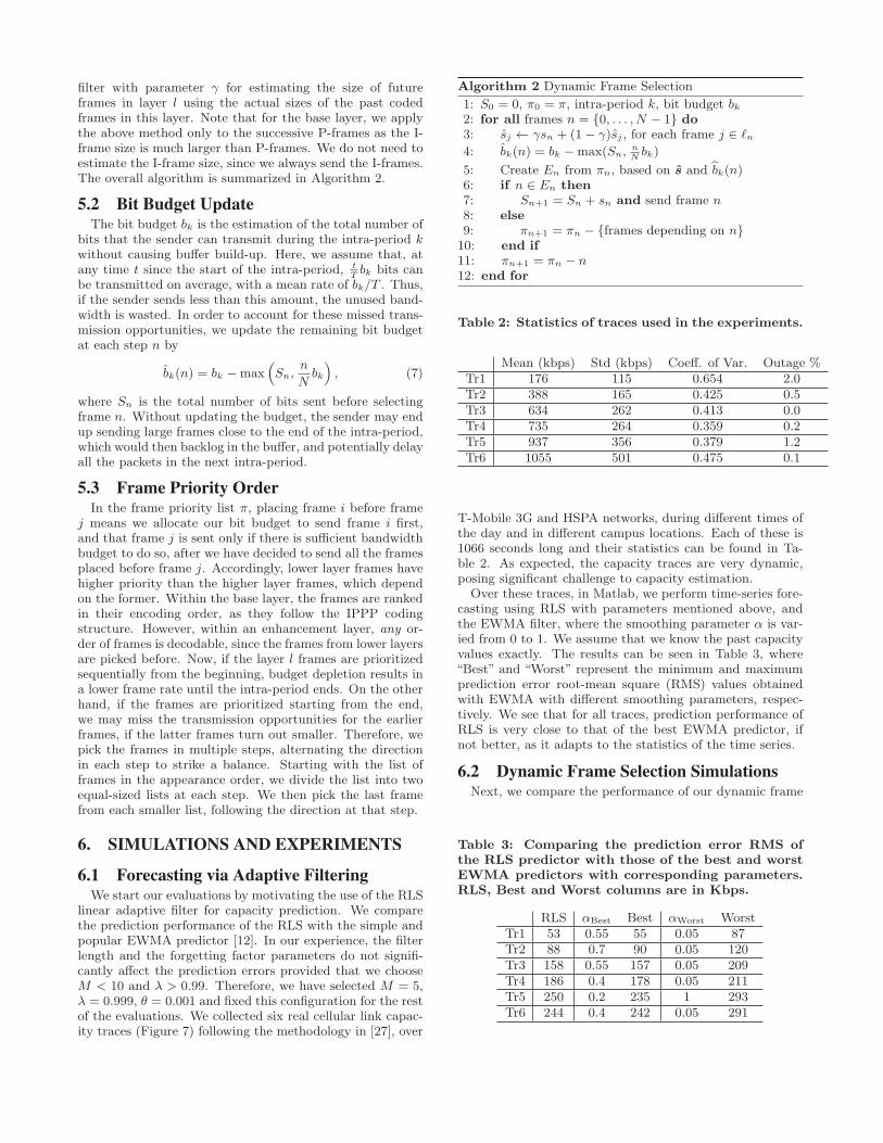
For each algorithm, we evaluate the total number of framessent, the mean and the standard deviation of the resultingframe intervals, and finally the fraction of the unused bitbudget. Here, a frame interval represents the temporal dis-tance between a pair of consecutive frames that have beenselected to be sent. The frame interval statistics are cal-culated using the fraction of time each interval lasts as theprobability to observe that interval. We use the JM en-coder [15] to encode the video sequence “Crew” [28] with ahierarchical-P structure having three temporal layers (GoPlength=4) and intra-period of 32 frames. We used a fixedquantization parameter (QP) of 36, yielding the average bi-trate of 415 kbps when all frames are included. The resultingvideo sequence has a frame rate of 30 fps and comprises 9intra-periods, with an intra-period of T = 32/30 seconds.For the proposed algorithm, we used γ = 0.75, which wasfound to perform the best, and the frame priority order isπ = (0, 4, 8, 12, 16, 20, 24, 28, 30, 14, 6, 22, 26, 18, 10,2, 31, 15, 7, 23, 27, 19, 11, 3, 1, 5, 9, 13, 17, 21, 25, 29).In these simulations, we assume that the bit budget bk isconstant for each intra-period k of the video and we wantto compare the performances of the algorithms describedabove under different bk values, from 10 kB to 80 kB. InFigure 4, we see that FP sends the most frames by sendingas many frames as possible. However, it also has the largestmean frame interval and the largest frame interval variation,making the displayed video jittery. On the other hand, theLP algorithm sends the lowest number of frames but alsowith lower mean frame interval and frame interval variance.The proposed DFS algorithm achieves a good compromisebetween sending more frames, consequently utilizing ABWmore closely, and reducing the frame distance variation. Infact, DFS outperforms both methods in terms of the meanand standard deviation of the frame intervals, while sendingalmost as many frames as the FP. Finally, the plot in theupper right shows the fraction of the unused bandwidth foreach method, where we see that the performance of DFS isvery similar to FP, whereas LP is not as efficient.
6.3 Evaluation on the TestbedFor system evaluation, we developed a testbed to compare
Rebera with popular video call applications. On this testbed(Figure 5), S and D are the source and destination end-points running the video call application under test, whilethe nodes CS and CD are cellular link emulators runningthe CellSim software [27], respectively. The emulators areconnected to each other through the campus network, andto their respective end-points via Ethernet. For cellular linkemulation, we use the uplink and downlink capacity tracescollected (Table 2). For evaluation, we report the ABW uti-lization, the 95-percentile one-way packet delays, and the95-percentile one-way frame delays as the performance met-
Rate budget (kB)20 40 60 80
Tot
al n
umbe
r of
fram
es s
ent
0
50
100
150
200
250
300DFSLPFP
Rate budget (kB)20 40 60 80
Unu
tiliz
ed b
udge
t fra
ctio
n
0
0.05
0.1
0.15
0.2
0.25
0.3
0.35
DFSLPFP
Rate budget (kB)20 40 60 80M
ean
fram
e in
terv
al (
fram
e-tim
e)
0
5
10
15
20
25DFSLPFP
Rate budget (kB)20 40 60 80R
MS
of f
ram
e in
terv
al (
fram
e-tim
e)
0
2
4
6
8
10
12
14
16DFSLPFP
Figure 4: Comparison of DFS with FP and LP;number of frames sent (upper-left), unused budget(upper-right), mean and standard deviation of theframe intervals (lower-left and lower-right). Encod-ing frame rate is 30 Hz, thus frame-time is 1/30 sec.
rics. In order to calculate the bandwidth utilization, wecount how many bytes were sent out by the video call appli-cation under test and compare it with the minimum of thecapacities of the sender link and the receiver link. The one-way end-to-end delays are collected by different means: inRebera experiments, for each packet that made it to the re-ceiver, the receiver sends an acknowledgement packet backto the sender over an ethernet cable on which there is noother traffic (Figure 5). As a result, the measured round-triptimes are almost equal to the one-way delays, enabling usto measure the delay for each individual packet and frame.In FaceTime experiments, we used Wireshark to sniff thepackets on the emulator hosts. We also note that FaceTimesends voice packets even after the voice is muted, at a con-stant rate of 32 kbps. Rebera, on the other hand, does notsend audio. In order to compensate for this in the bandwidthutilization calculations, we subtract 32 kbps from the send-ing rate achieved by Rebera. In each test, we loop the videosequence “Crew”, which is more challenging in terms of thevideo rate than ”Akiyo” and somewhat captures hand/armmovements present in video calls.
Rebera is able to encode the video in real-time thanks tothe open source x264 video encoder [24]. This allows us tochange the video rate according to the predicted ABW, foreach new intra-period, using x264’s rate control module. Wehave modified x264’s code, so that the encoded video has ahierarchical-P coding structure, by changing the referenceframes used before encoding each frame according to theH.264/AVC standard. Specifically, in our modification, theGoP length is set to 4, giving rise to 3 temporal layers. Inall our experiments in the lab, the minimum and maximumencoding rates were set as 200 kbps and 3 Mbps, respec-
NYU Network
S D
CS CD
eth0eth1
eth0eth1
Figure 5: Illustration of the testbed. Purple arrowsindicate the flow direction of the video, whereas theacks follow the green arrow from D to S.
Intra-period index0 100 200 300 400 500 600 700
kbps
0
100
200
300
400
500
600 Rebera measured bandwidthRebera in-queueRebera budgetRebera sending rateFaceTime sending rate
Figure 6: Sending rate of Rebera and FaceTime un-der piecewise constant bandwidth.
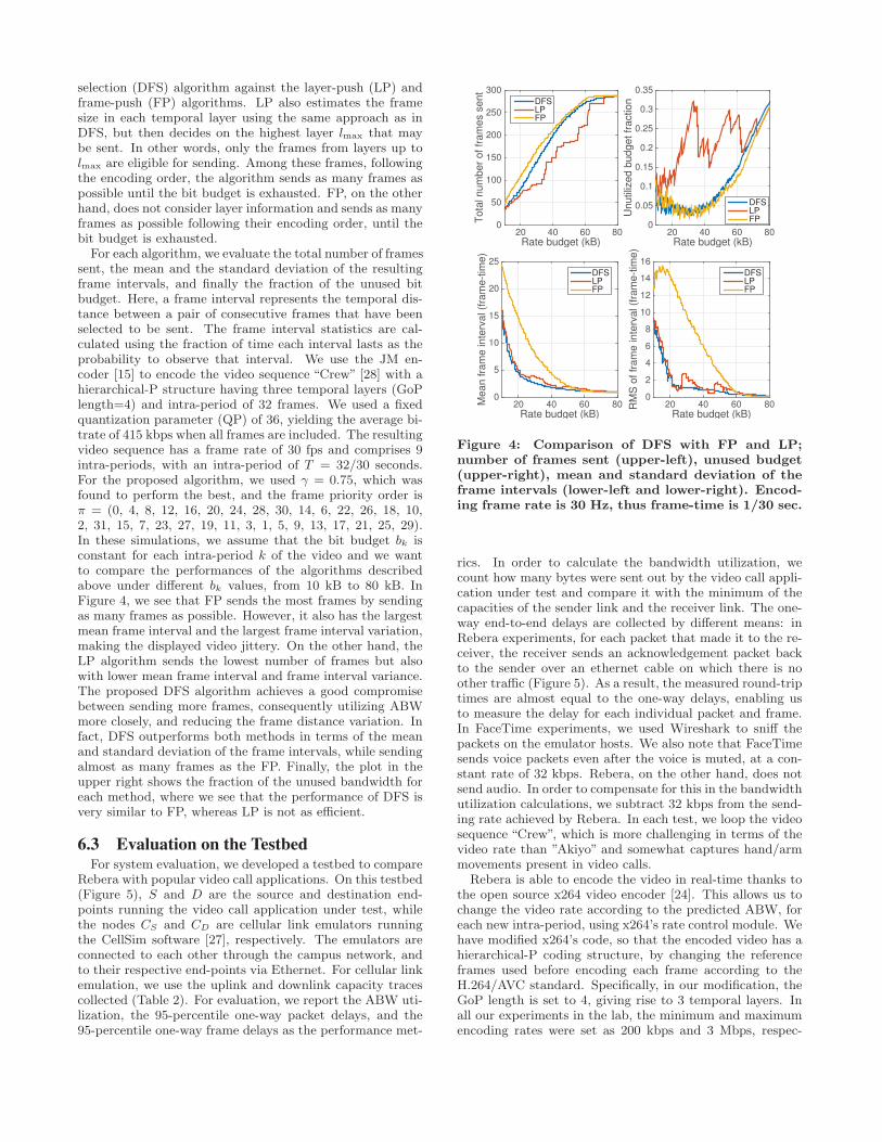
tively. The video and RLS parameters used are the same asin Sections 6.2 and 6.1. Specifically, the encoding frame rateis 30 Hz, and the intra-period length T is 32 frames, or 1.066seconds. The initial sending rate is set to 120 kbps. In eachexperiment, we evaluate the sending rate over consecutiveperiods of T seconds. Please note that FaceTime may notbe using a constant intra-period, let alone the same intra-period T as Rebera. Furthermore, FaceTime’s sending rateis, in general, the sum of FEC and the video data rates. Inorder to feed the same looped test video into FaceTime, weused the ManyCam [25] virtual webcam on Mac OS 10.10.41.
6.3.1 Evaluation with Piecewise Constant BandwidthIn this experiment, we use a piecewise constant bandwidth
trace, with steps of 100 kbps lasting 100 seconds, between300 and 600 kbps. We set the packet loss rate to zero. InFigure 6, we can see Rebera’s (i) measured bandwidth, (ii)rate reduction due to the estimated number of backloggedbits, (iii) overall budget and (iv) the sending rate, along withFaceTime’s sending rate. On average, the bandwidth utiliza-tion of Rebera is 86.21%, while FaceTime achieves a utiliza-tion of 78.78%. Moreover, we can observe that, Rebera isable to measure the current bandwidth very accurately, andthus react to the changes in the bandwidth rapidly.
6.3.2 Evaluation with Cellular Capacity Traces1Detailed explanations can be found online at [1].
0 200 400 600 800 10000
0.5 Tr1
0 200 400 600 800 10000
0.5 Tr2
0 200 400 600 800 10000
1 Tr3
0 200 400 600 800 1000012 Tr4
0 200 400 600 800 10000
2Tr5
0 200 400 600 800 10000
2Tr6
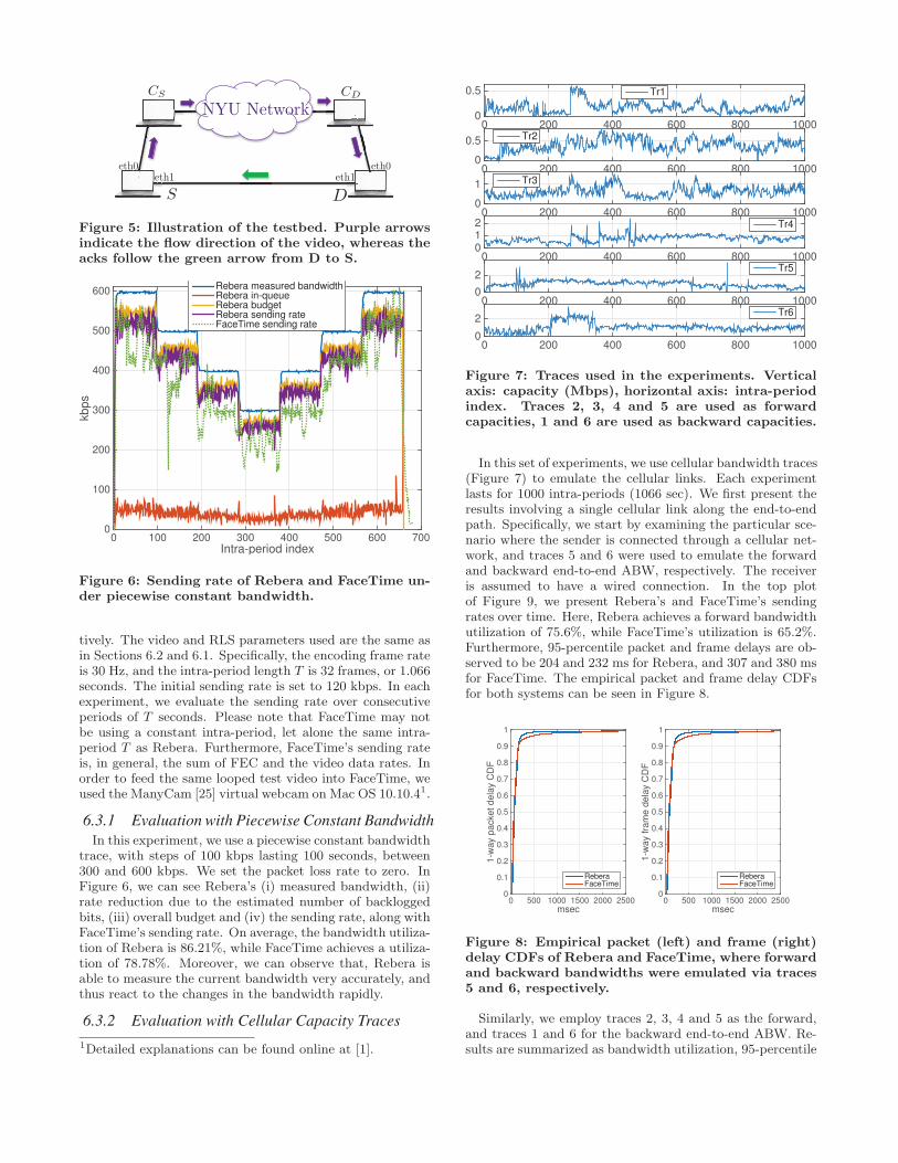
Figure 7: Traces used in the experiments. Verticalaxis: capacity (Mbps), horizontal axis: intra-periodindex. Traces 2, 3, 4 and 5 are used as forwardcapacities, 1 and 6 are used as backward capacities.
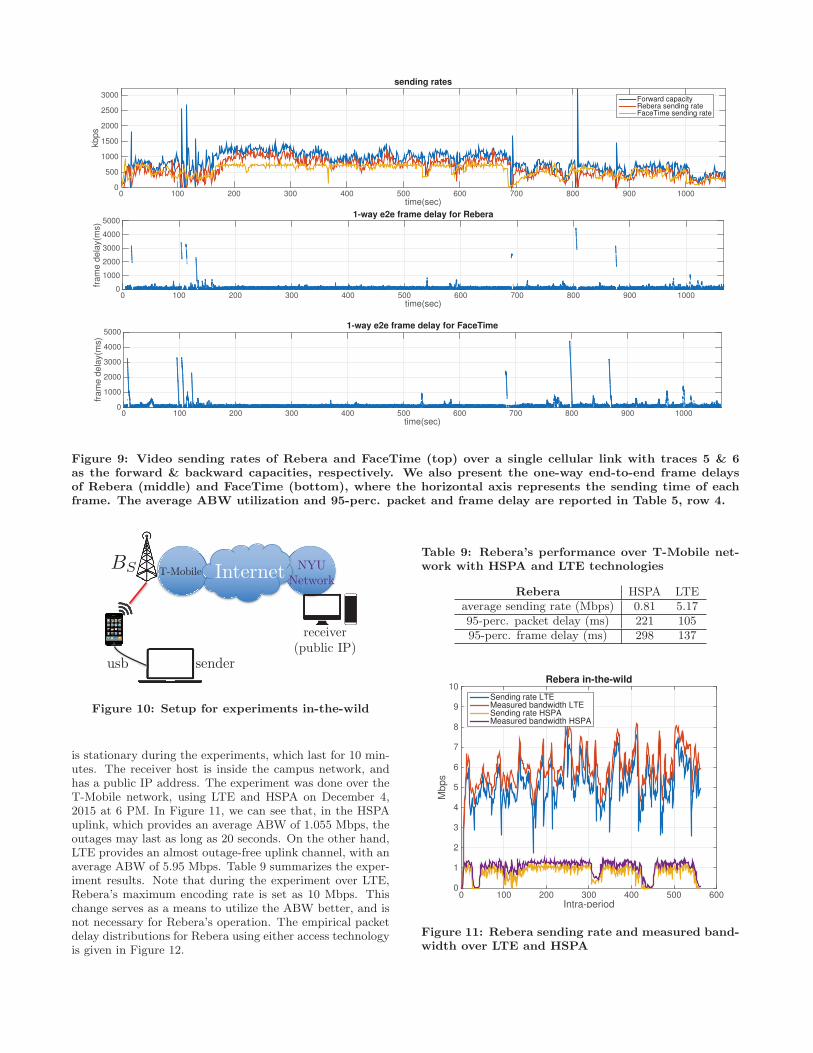
In this set of experiments, we use cellular bandwidth traces(Figure 7) to emulate the cellular links. Each experimentlasts for 1000 intra-periods (1066 sec). We first present theresults involving a single cellular link along the end-to-endpath. Specifically, we start by examining the particular sce-nario where the sender is connected through a cellular net-work, and traces 5 and 6 were used to emulate the forwardand backward end-to-end ABW, respectively. The receiveris assumed to have a wired connection. In the top plotof Figure 9, we present Rebera’s and FaceTime’s sendingrates over time. Here, Rebera achieves a forward bandwidthutilization of 75.6%, while FaceTime’s utilization is 65.2%.Furthermore, 95-percentile packet and frame delays are ob-served to be 204 and 232 ms for Rebera, and 307 and 380 msfor FaceTime. The empirical packet and frame delay CDFsfor both systems can be seen in Figure 8.
msec0 500 1000 1500 2000 2500
1-w
ay p
acke
t del
ay C
DF
0
0.1
0.2
0.3
0.4
0.5
0.6
0.7
0.8
0.9
1
ReberaFaceTime
msec0 500 1000 1500 2000 2500
1-w
ay fr
ame
dela
y C
DF
0
0.1
0.2
0.3
0.4
0.5
0.6
0.7
0.8
0.9
1
ReberaFaceTime
Figure 8: Empirical packet (left) and frame (right)delay CDFs of Rebera and FaceTime, where forwardand backward bandwidths were emulated via traces5 and 6, respectively.
Similarly, we employ traces 2, 3, 4 and 5 as the forward,and traces 1 and 6 for the backward end-to-end ABW. Re-sults are summarized as bandwidth utilization, 95-percentile

Table 4: Evaluation over single cellular link, usingTrace 1 as the backward capacity. Reported val-ues are bandwidth utilization percentage, 95-perc.packet delay, and 95-perc. frame delay, respectively.
Fwd Cap. Rebera(%,ms,ms) FaceTime(%,ms,ms)Trace 2 68.8, 402, 402 58.1, 447, 415Trace 3 63.8, 338, 334 32.7, 631, 528Trace 4 73.5, 177, 201 63.0, 383, 392Trace 5 71.8, 216, 243 58.7, 317, 341Average 69.5, 283, 295 53.1, 444, 419
Table 5: Evaluation over single cellular link, usingTrace 6 as the backward capacity. Reported val-ues are bandwidth utilization percentage, 95-perc.packet delay, and 95-perc. frame delay, respectively.
Fwd. Cap. Rebera(%,ms,ms) FaceTime(%,ms,ms)Trace 2 69.5, 381, 394 59.2, 426, 406Trace 3 66.4, 307, 313 61.9, 341, 349Trace 4 76.1, 168, 189 70.6, 276, 307Trace 5 75.6, 204, 232 65.2, 307, 380Average 71.9, 265, 282 64.2, 337, 360
packet and frame delay tuples in Tables 4 and 5. We can seefrom Table 4 and 5 that in all experiments, Rebera achieves ahigher utilization of the forward ABW with shorter delays.Averaged over these experiments, Rebera provides 20.5%higher bandwidth utilization compared to FaceTime, and areduction of 122 ms and 102 ms in the 95-percentile packetand frame queueing delays, respectively. When a more chal-lenging backward capacity (trace 1 in Table 4) is used for thebackward path, the information fed back to the sender sideundergo a longer delay for both Rebera and FaceTime, de-creasing the ABW utilization of both systems. FaceTime’sdelay performance also degrades, whereas Rebera is still ableto provide similar delays.
Next, we consider the scenarios where both users are con-nected over different cellular links. We assume there existsthree different cellular connections, which we denote by A,B and C, where the uplink and downlink ABW pairs foreach connection are given as traces 5 and 6, traces 3 and 4,and traces 1 and 2, respectively. In other words, connectionA provides the highest mean ABW, while the connectionC provides the lowest. We evaluate all six cases for whichthe sender and the receiver have different connections. Theresults can be seen in Table 6. In all scenarios, Rebera pro-vides a significantly higher ABW utilization, while still de-livering shorter packet and frame delays on average and inmost cases.
6.3.3 Effect of the Tolerance ParameterNext, we investigate the effect of the tolerance parameter
δ in Section 4.3 on Rebera. We vary δ from 0.05 up to 0.5,and record the utilization and 95-percentile packet delays inTable 7. Having a larger δ value means the system is willingto tolerate more frequent capacity overshoots, and hence
Table 6: Evaluation when both users are connectedover different cellular networks. Reported values arebandwidth utilization percentage, 95-perc. packetdelay, and 95-perc. frame delay, respectively.
Rebera(%,ms,ms) FaceTime(%,ms,ms)A to B 60.5, 300, 312 47.9, 529, 508B to A 58.1, 483, 498 48.5, 485, 483A to C 59.9, 432, 442 44.0, 588, 518C to A 61.3, 1066, 1019 43.3, 1278, 851B to C 61.2, 416, 419 28.2, 1180, 996C to B 59.5, 804, 809 44.0, 3230, 1090Average 60.1, 583, 583 42.6, 1215, 741
Table 7: Effect of the tolerance parameter on Reberaover single cellular link. Forward-backward capac-ity: traces 3-6
δ 0.05 0.1 0.2 0.5ABW utilization (%) 66.4 69.6 72.7 75.36
95-perc. packet delay (ms) 307 354 371 48695-perc. frame delay (ms) 313 367 403 516
more frequent large packet and frame delays, in exchangefor higher bandwidth utilization, which could be the case forvideo applications with less stringent delay requirements.
6.3.4 Rebera Bahavior in Presence of Packet LossThe purpose of this evaluation is to demonstrate that Re-
bera can still track the link capacity in the presence of packetloss. Note that additional studies are needed to investigatethe error resilience provided by the temporal layering, andhow to further improve it through unequal error protection.To examine the performance of Rebera in presence of packetloss, we employ CellSim to introduce random iid losses. Wetested Rebera when the packet loss rate is 5% and 10%, andthe results are given in Table 8. Although not significantly,the ABW utilization drops with the loss rate, as there arefewer packets crossing the links. Furthermore, the delays ex-perienced by the received frames reduce, since there is lessbacklog in the buffers.
Table 8: Effect of the packet losses on Rebera oversingle cellular link. Forward-backward capacities:traces 3-6
Packet loss rate 0% 5% 10%ABW utilization (%) 66.4 63.4 61.1
95-perc. packet delay (ms) 307 281 286
6.4 Evaluation over Cellular NetworksFinally, we evaluate Rebera over a real cellular network.
The setup we used for this experiment can be seen in Figure10. Here, a mobile device (Motorola Nexus 6) is tethered tothe sender host via USB, acting as a modem. The sender
time(sec)0 100 200 300 400 500 600 700 800 900 1000
kbps
0
500
1000
1500
2000
2500
3000
sending rates
Forward capacityRebera sending rateFaceTime sending rate
time(sec)0 100 200 300 400 500 600 700 800 900 1000
fram
e de
lay(
ms)
0
1000
2000
3000
4000
50001-way e2e frame delay for Rebera
time(sec)0 100 200 300 400 500 600 700 800 900 1000
fram
e de
lay(
ms)
0
1000
2000
3000
4000
50001-way e2e frame delay for FaceTime
Figure 9: Video sending rates of Rebera and FaceTime (top) over a single cellular link with traces 5 & 6as the forward & backward capacities, respectively. We also present the one-way end-to-end frame delaysof Rebera (middle) and FaceTime (bottom), where the horizontal axis represents the sending time of eachframe. The average ABW utilization and 95-perc. packet and frame delay are reported in Table 5, row 4.
BS Internet
usb sender
T-MobileNYU
Network
receiver(public IP)
Figure 10: Setup for experiments in-the-wild
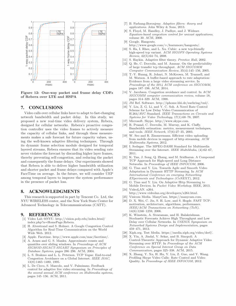
is stationary during the experiments, which last for 10 min-utes. The receiver host is inside the campus network, andhas a public IP address. The experiment was done over theT-Mobile network, using LTE and HSPA on December 4,2015 at 6 PM. In Figure 11, we can see that, in the HSPAuplink, which provides an average ABW of 1.055 Mbps, theoutages may last as long as 20 seconds. On the other hand,LTE provides an almost outage-free uplink channel, with anaverage ABW of 5.95 Mbps. Table 9 summarizes the exper-iment results. Note that during the experiment over LTE,Rebera’s maximum encoding rate is set as 10 Mbps. Thischange serves as a means to utilize the ABW better, and isnot necessary for Rebera’s operation. The empirical packetdelay distributions for Rebera using either access technologyis given in Figure 12.
Table 9: Rebera’s performance over T-Mobile net-work with HSPA and LTE technologies
Rebera HSPA LTEaverage sending rate (Mbps) 0.81 5.1795-perc. packet delay (ms) 221 10595-perc. frame delay (ms) 298 137
Intra-period0 100 200 300 400 500 600
Mbp
s
0
1
2
3
4
5
6
7
8
9
10Rebera in-the-wild
Sending rate LTEMeasured bandwidth LTESending rate HSPAMeasured bandwidth HSPA
Figure 11: Rebera sending rate and measured band-width over LTE and HSPA
msec0 200 400
1-w
ay p
acke
t del
ay C
DF
0
0.1
0.2
0.3
0.4
0.5
0.6
0.7
0.8
0.9
1
LTEHSPA
msec0 200 400
1-w
ay fr
ame
dela
y C
DF
0
0.1
0.2
0.3
0.4
0.5
0.6
0.7
0.8
0.9
1
LTEHSPA
Figure 12: One-way packet and frame delay CDFsof Rebera over LTE and HSPA
7. CONCLUSIONSVideo calls over cellular links have to adapt to fast-changing
network bandwidth and packet delay. In this study, weproposed a new real-time video delivery system, Rebera,designed for cellular networks. Rebera’s proactive conges-tion controller uses the video frames to actively measurethe capacity of cellular links, and through these measure-ments makes a safe forecast for future capacity values, us-ing the well-known adaptive filtering techniques. Throughits dynamic frame selection module designed for temporallayered streams, Rebera ensures that its video sending ratenever violates the forecast by discarding higher layer frames,thereby preventing self-congestion, and reducing the packetand consequently the frame delays. Our experiments showedthat Rebera is able to deliver higher bandwidth utilizationand shorter packet and frame delays compared with Apple’sFaceTime on average. In the future, we will consider UEPamong temporal layers to improve the system performancein the presence of packet loss.
8. ACKNOWLEDGMENTSThis research is supported in part by Tencent Co. Ltd, the
NYUWIRELESS center, and the New York State Center forAdvanced Technology in Telecommunications (CATT).
9. REFERENCES[1] Video Lab @NYU. http://vision.poly.edu/index.html/
index.php?n=HomePage.Rebera.[2] H. Alvestrand and S. Holmer. A Google Congestion Control
Algorithm for Real-Time Communication on the WorldWide Web. 2012.
[3] Apple. Facetime. http://www.apple.com/mac/facetime/.[4] A. Arasu and G. S. Manku. Approximate counts and
quantiles over sliding windows. In Proceedings of ACMSIGMOD-SIGACT-SIGART Symposium on Principles ofDatabase Systems, pages 286–296. ACM, 2004.
[5] L. S. Brakmo and L. L. Peterson. TCP Vegas: End-to-endCongestion Avoidance on a Global Internet. IEEE JSAC,13(8):1465–1480, 1995.
[6] L. De Cicco, S. Mascolo, and V. Palmisano. Feedbackcontrol for adaptive live video streaming. In Proceedings ofthe second annual ACM conference on Multimedia systems,pages 145–156. ACM, 2011.
[7] B. Farhang-Boroujeny. Adaptive filters: theory andapplications. John Wiley & Sons, 2013.
[8] S. Floyd, M. Handley, J. Padhye, and J. Widmer.Equation-based congestion control for unicast applications,volume 30. ACM, 2000.
[9] Google. Hangouts.http://www.google.com/+/learnmore/hangouts/.
[10] S. Ha, I. Rhee, and L. Xu. Cubic: a new tcp-friendlyhigh-speed tcp variant. ACM SIGOPS Operating SystemsReview, 42(5):64–74, 2008.
[11] S. Haykin. Adaptive filter theory. Prentice Hall, 2002.[12] Q. He, C. Dovrolis, and M. Ammar. On the predictability
of large transfer tcp throughput. ACM SIGCOMMComputer Communication Review, 35(4):145–156, 2005.
[13] T.-Y. Huang, R. Johari, N. McKeown, M. Trunnell, andM. Watson. A buffer-based approach to rate adaptation:Evidence from a large video streaming service. InProceedings of the 2014 ACM conference on SIGCOMM,pages 187–198. ACM, 2014.
[14] V. Jacobson. Congestion avoidance and control. In ACMSIGCOMM computer communication review, volume 18,pages 314–329. ACM, 1988.
[15] JM Ref. Software. http://iphome.hhi.de/suehring/tml/.[16] Y. Liu, Z. G. Li, and Y. C. Soh. A Novel Rate Control
Scheme for Low Delay Video Communication ofH.264/AVC Standard. IEEE Transactions on Circuits andSystems for Video Technology, 17(1):68–78, 2007.
[17] Microsoft. Skype. http://www.skype.com.[18] R. Prasad, C. Dovrolis, M. Murray, and K. Claffy.
Bandwidth estimation: metrics, measurement techniques,and tools. IEEE Network, 17(6):27–35, 2003.
[19] W. Seo and R. Zimmermann. Efficient video uploadingfrom mobile devices in support of http streaming. ACMMultimedia Systems, 2012.
[20] I. Sodagar. The MPEG-DASH Standard for MultimediaStreaming over the Internet. IEEE MultiMedia, (4):62–67,2011.
[21] K. Tan, J. Song, Q. Zhang, and M. Sridharan. A CompoundTCP Approach for High-speed and Long DistanceNetworks. In Proceedings of IEEE INFOCOM, 2006.
[22] G. Tian and Y. Liu. Towards Agile and Smooth VideoAdaptation in Dynamic HTTP Streaming. In ACMInternational Conference on emerging NetworkingEXperiments and Technologies (CoNEXT), 2012.
[23] G. Tian and Y. Liu. On Adaptive Http Streaming toMobile Devices. In Packet Video Workshop. IEEE, 2013.
[24] VideoLAN. x264.http://www.videolan.org/developers/x264.html.
[25] Visicom Media. ManyCam. https://manycam.com.[26] D. X. Wei, C. Jin, S. H. Low, and S. Hegde. FAST TCP:
motivation, architecture, algorithms, performance.IEEE/ACM Transactions on Networking (ToN),14(6):1246–1259, 2006.
[27] K. Winstein, A. Sivaraman, and H. Balakrishnan.Stochastic Forecasts Achieve High Throughput and LowDelay over Cellular Networks. In USENIX Symposium onNetworked Systems Design and Implementation, pages459–471, 2013.
[28] Xiph.org. Test Media. https://media.xiph.org/video/derf/.[29] X. Yin, A. Jindal, V. Sekar, and B. Sinopoli. A
Control-Theoretic Approach for Dynamic Adaptive VideoStreaming over HTTP. In Proceedings of the ACMConference on Special Interest Group on DataCommunication, pages 325–338. ACM, 2015.
[30] X. Zhang, Y. Xu, H. Hu, Y. Liu, Z. Guo, and Y. Wang.Profiling Skype Video Calls: Rate Control and VideoQuality. In Proceedings of IEEE INFOCOM, 2012.