read this before installing switchgear
TRANSCRIPT

R
EAD
TH
IS B
EFO
RE
INST
ALL
ING
SW
ITC
HG
EAR


9087A – 198th Street, Langley, BC Canada V1M 3B1 Telephone (604) 888-0110 Telefax (604) 888-3381 E-Mail: [email protected] www.thomsonPScom
SYSTEM 2000
SWITCHGEAR
INSTALLATION GUIDE
PM073 Rev 1 14/02/17

SYSTEM 2000 SWITCHGEAR INSTALLATION GUIDE
PM073 REV 1 14/02/17 Thomson Power Systems
TABLE OF CONTENTS
1. EQUIPMENT STORAGE 1
2. EQUIPMENT OPERATING 1
3. ELECTRICAL RATINGS 2
4. ENCLOSURE TYPE 2
5. SWITCHGEAR ACCESS 2
6. VENTILATION 2
7. FLOOR MOUNTING 2
8. BOLT DOWN PROVISIONS 3
9. SHIPPING SPLITS 3
10. CABLE CONNECTIONS 4
11. CABLE TORQUE REQUIREMENTS 4
11.1. Blackburn - Thomas & Betts Tightening Torque Values 4 11.2. Ilsco Tightening Torque Values 5 11.3. ABB Tightening Torque Values 5
12. EXTERNAL WIRING 7
13. CLEANING 8
14. INSULATION RESISTANCE TESTING/ DIELECTRIC TESTING 8
15. BATTERY CHARGER 8
16. INSTALLATION MOUNTING DRAWINGS 9

SYSTEM 2000 SWITCHGEAR INSTALLATION GUIDE
PM073 REV 1 14/02/17 1 Thomson Power Systems
NOTE: The following information is provided as a general guide for installing Thomson Power
Systems System 2000 Switchgear in typical applications. System installations must be done in
accordance with all applicable local and national electrical regulation codes and practices as
required. If you have any concerns or require detailed information to aid in installation, contact
the Thomson Power Systems Service Group.
1. EQUIPMENT STORAGE
CAUTION!!! Failure to store and operate equipment under the specified environmental conditions
may cause equipment damage and void warranty.
The switchgear shall be stored in an environment with a temperature range not exceeding -4°
to +158° Fahrenheit (-20° to +70° Celsius) and a humidity range not exceeding 5%-95% non-
condensing. Before storing, unpack sufficiently to check for concealed damage. If concealed
damage is found, notify the switchgear supplier and the carrier immediately. Repack with the
original, or equivalent packing materials. Protect from physical damage. Store indoor in a
clean, dry, well-ventilated area free of corrosive agents including fumes, salt and
concrete/cement dust. Apply heat as necessary to prevent condensation.
NOTE: If the switchboard is unpacked and positioned prior to completion of room/building
construction, heavy cardboard should be used to protect the equipment and wiring from
damage, dirt, and defacing during building construction.
2. EQUIPMENT OPERATING The switchgear shall be operated in an environment with a temperature range not exceeding
+5° to +122° Fahrenheit (-15° to +50° Celsius) and a humidity range not exceeding 5%-95%
non-condensing.

SYSTEM 2000 SWITCHGEAR INSTALLATION GUIDE
PM073 REV 1 14/02/17 2 Thomson Power Systems
3. ELECTRICAL RATINGS Before installing the switchgear ensure all electrical ratings of the equipment (i.e. voltage (AC
and DC), current and interrupting ratings etc.) are suitable for the system it is being connected
to. All equipment ratings are shown on an Equipment Identification nameplate on the front
door(s) of the switchgear.
Also verify cable entries are in the correct location and power connection (lugs) are suitable.
Check that the appropriate system configuration is supplied 1-Phase, 2-Wire / 1-Phase, 3-Wire
/ 3-Phase, 3-Wire / 3-Phase, 4-Wire.
4. ENCLOSURE TYPE Ensure the enclosure type is correct for the environment the switchgear is being installed.
• NEMA1 Indoor (ventilated - no protection)
• NEMA2 Indoor (some protection against vertical drops of water i.e. condensation)
• NEMA12 Indoor (oil and dust tight - gaskets and filter media)
• NEMA3R Outdoor (weather proof)
• Other
5. SWITCHGEAR ACCESS Standard switchgear designs require front and rear access. Sufficient access and working
space shall be provided to permit safe operation and maintenance of the switchgear. Minimum
clear distances for all workspace around the switchgear shall be provided as defined in the
National Electrical code (NEC) or Canadian Electrical code (CEC).
6. VENTILATION Unless there is specific requirement, switchgear is provided with ventilation (front and back).
The ventilation must not be blocked or reduced in anyway.
7. FLOOR MOUNTING The switchgear is suitable only for installation on a non-combustible floor.
It is critical that a flat, even and level finished floor is provided. If the floor is not level it will
cause distortion of the switchgear; most noticeably:

SYSTEM 2000 SWITCHGEAR INSTALLATION GUIDE
PM073 REV 1 14/02/17 3 Thomson Power Systems
Hinged doors will not line up and may not swing freely.
Removable covers may not line up.
Bus splice plates may be difficult to install.
General stress on the enclosure, bus and bus supports.
8. BOLT DOWN PROVISIONS Standard Thomson Power Systems System 2000 switchgear enclosures include provisions for
fastening the enclosure to the floor; refer to drawing 099C005.
9. SHIPPING SPLITS Large switchgear lineups are provided with shipping splits. When placing the switchgear
ensure the sections are lined up and placed tightly together without a gap. Do not use the
hardware supplied to pull the sections together. This will deform the structure.
Nuts and bolts will be supplied to join the perforated rails every 18 - 24". Insert the bolts per
drawing 099C004, spaced every 18 - 24". Just hand tighten until all sections have been joined.
Once all bolts have been placed in a satisfactory pattern, tighten the bolts using a wrench.
Where load bus bars cross a shipping split, the load bus will be drilled and bus splice plates
provided. The necessary hardware will be provided to connect the bus across the shipping split
on site, refer to drawing 099C002, 099C003 and CDB1242 as applicable.
CAUTION!!! Before placing the switchgear into service, it is imperative to check all electrical connections and mechanical fasteners for correct tightness. Failure to do so may cause
severe equipment damage or failure.
Control wiring that spans the shipping split will be fitted across the shipping split at the factory.
The wiring will terminate at a terminal strip. Prior to shipping, the wiring will be disconnected at
the terminal strip, pulled back and bundled within the control compartment. Once the
switchgear has been placed and joined, the wiring can be drawn back across the shipping split
and reconnected at the terminal strip. The wire numbers match the terminal numbers; any

SYSTEM 2000 SWITCHGEAR INSTALLATION GUIDE
PM073 REV 1 14/02/17 4 Thomson Power Systems
variation will be shown on the "As Built" schematics shipped with the switchgear; reference
these schematics when reconnecting the wiring.
10. CABLE CONNECTIONS During power cable installation, ensure the phasing of all line/load conductors are correctly
matched between the connected sources and the switchgear bus bar.
NOTE: Unless otherwise stated in the switchgear drawings, the switchgear is designed as standard to
accept sources with a positive (i.e. A-B-C) phase rotation. It is recommended the phase
rotation of the system sources be confirmed prior to installation of the power caballing.
All cable lugs shall be adequately torqued as per the following manufacturer's instructions.
CAUTION!!! Before placing the switchgear into service, it is imperative to check all electrical connections and mechanical fasteners for correct tightness. Failure to do so may cause
severe equipment damage or failure.
11. CABLE TORQUE REQUIREMENTS 11.1. Blackburn - Thomas & Betts Tightening Torque Values ADR21, T&B, LUG, SCREW TYPE, (1)#14-2/0 CU/AL
ADR25, T&B, LUG, SCREW TYPE, (1)#6-250MCM
ADR35, T&B, LUG, SCREW TYPE, (1) #6-350MCM
ADR60, T&B, LUG, SCREW TYPE, (1)#2-600MCM
Tightening Torque Values for Aluminum Dual Rated Socket Screw Connectors
AWG or Circular Mll size
Tightening Torque is in lb. Screw Driver Wrench
AWG or Circular Mll size
Tightening Torque is in lb. Screw Driver Wrench
12 20 75 400 - 200
10 20 75 250 - 250
9 20 75 350 - 250
6 35 100 500 - 300

SYSTEM 2000 SWITCHGEAR INSTALLATION GUIDE
PM073 REV 1 14/02/17 5 Thomson Power Systems
Tightening Torque Values for Aluminum Dual Rated Socket Screw Connectors
AWG or Circular Mll size
Tightening Torque is in lb. Screw Driver Wrench
AWG or Circular Mll size
Tightening Torque is in lb. Screw Driver Wrench
4 35 100 600 - 300
2 50 125 700 - 300
1 50 125 750 - 300
1/0 50 150 900 - 400
2/0 50 150 1000 - 400
3/0 - 200
11.2. Ilsco Tightening Torque Values TA800I, ILSCO, LUG, SCREW TYPE, (1) 300-800MCM CU/AL
Tightening Torque Values for ILSCO Socket head Screw Connectors Internal Socket Size Across Flats Inches Tightening Torque in Inch Pounds
1/8 45 5/32 100 3/16 120 7/32 150 1/4 200
5/16 275 3/8 375 1/2 500
9/16 600
11.3. ABB Tightening Torque Values K6TP, ABB, BREAKER LUG KIT, 800A, S6 3 LUGS/KIT, (3) 2/0-500MCM CU/AL
K4TB, ABB, BREAKER LUG KIT, 100A, S3-4 3 LUGS/KIT, (1)#14-1/0 CU/AL
K7TK, ABB, BREAKER LUG KIT, 1200A, S7 CSA/UL, SINGLE UNIT
K4TC, ABB, BREAKER LUG KIT, 150A, S3-4 3 LUGS/KIT, (1)#2-4/0 CU/AL
K4TE, ABB, BREAKER LUG KIT, 250A, S4 3 LUGS/KIT, (1)#6-350MCM CU/AL
K5TG, ABB, BREAKER LUG KIT, 400A, S5 3 LUGS/KIT, (2) 3/0-250MCM CU/AL
K5TF, ABB, BREAKER, LUG KIT, 300A, S5 (1) 250-500MCM CU/AL, 3 LUGS/KIT
K5TGS, ABB, BREAKER, LUG KIT, SADDLE, S5 (1) 250-500MCM CU, 6 LUGS/KIT
K7TK-1, ABB, BREAKER, LUG, 1000 - 1200A, 4/0-500 MCM, CSA/UL, SINGLE UNIT

SYSTEM 2000 SWITCHGEAR INSTALLATION GUIDE
PM073 REV 1 14/02/17 6 Thomson Power Systems
K6THW, ABB, BREAKER, LUG, 400/600A, S6 ALT# K6THW-B100 (2) 2/0-500MCM
CU/AL, CSA/UL
WIRE RANGE WIRE TORQUE 14 AWG – 8 AWG 22 lb-in 6 AWG – 3 AWG 44 lb-in
COPPER WIRE ONLY
FIGURE LUG KIT CAT. NO. LUG NO. TEMP. WIRE RANGE WIRE
TORQUE MOUNTING
TORQUE WIRE
SCREW SIZE
A K3TA, K3TA-2 D3477 75°C 14 AWG – 2 AWG 50 lb-in 120 lb-in SLOT B K4TB, K4TB-2 D3447 75°C 14 AWG – 1.0 50 lb-in 120 lb-in SLOT C K4TC, K4TC-2 D3449 75°C 2 AWG – 4.0 120 lb-in 150 lb-in 3/16 D K4TD, K4TD-2 D3448 75°C 4 AWG –300kcmII 275 lb-in 150 lb-in 1/4
FIGURE LUG KIT CAT. NO. LUG NO. TEMP. WIRE RANGE WIRE
TORQUE MOUNTING
TORQUE WIRE
SCREW SIZE
A K4TB, K4TB-2 D3447 75°C 14 AWG – 1.0 50 lb-in 120 lb-in SLOT B K4TC, K4TC-2 D3449 75°C 2 AWG – 4.0 120 lb-in 150 lb-in 3/16 C K4TD, K4TD-2 D3448 75°C 4AWG – 300 kcmII 275 lb-in 150 lb-in 1/4 D K4TE, K4TE-2 D3472 75°C 6 AWG –350kcmII 275 lb-in 150 lb-in 5/16
FIGURE LUG KIT CAT. NO. LUG NO. TEMP. WIRE RANGE WIRE
TORQUE MOUNTING
TORQUE WIRE
SCREW SIZE
F K5TF, K5TF-2 D3450 75°C 250 – 500kcmII 375 lb-in 175 lb-in 3/8 G K4TC, K4TC-2 D3484 75°C 3.0 – 250kcmII (2) 275 lb-in 175 lb-in 5/18
FIGURE LUG KIT CAT. NO. LUG NO. TEMP. WIRE RANGE WIRE
TORQUE MOUNTING
TORQUE WIRE
SCREW SIZE
H K6TH, K6TH-2 D2967 90°C 250 – 500kcmII 275 lb-in 85 lb-in 5/16 J K6TJ, K6TJ-2 D2968 90°C 2.0 – 400kcmII (2) 375 lb-in 110 lb-in 3/8
FIGURE LUG KIT CAT. NO. LUG NO. TEMP. WIRE RANGE WIRE
TORQUE MOUNTING
TORQUE WIRE
SCREW SIZE
K K7TK, K7TK-2 D2959 90°C 4.0 – 500kcmII (4) 375 lb-in 375 lb-in 2/8
FIGURE LUG KIT CAT. NO. LUG NO. TEMP. WIRE RANGE WIRE
TORQUE MOUNTING
TORQUE WIRE
SCREW SIZE
L K8TL D1922 90°C 1.0 – 750kcmII (4) 500 lb-in 500 lb-in 1/2
M K8TM D3185, D3188, D3187
90°C 1.0 – 750kcmII (6) 500 lb-in 500 lb-in 1/2

SYSTEM 2000 SWITCHGEAR INSTALLATION GUIDE
PM073 REV 1 14/02/17 7 Thomson Power Systems
12. EXTERNAL WIRING The "As Built" switchgear schematics are shipped with the switchgear.
The following general guidelines apply to external wiring connections between auxiliary
systems and the switchgear. Specific customer requirements, the National and/or local
electrical code requirements shall take precedence over these guidelines.
Control wiring must not be run unshielded, in parallel, and in close proximity to power
cables.
AC and DC wiring shall be run separately.
In general, control wiring is #14AWG (2.5mmSQ) minimum unless it is determined a
smaller gauge conductor is suitable.
Recommend #10AWG (6mmSQ) for current transformer (CT) connections.
Shielded cable #18AWG (0.75mmSQ) minimum Belden 8760 or equal. Larger if
required due to distance.
Communication cable wiring from the switchgear to remote devices must be suitably
routed to protect it from sources of electrical interference. Guidelines for protection
against possible electrical interference are as follows:
• Use high quality, shielded communication cable as specified on switchgear
drawings.
• Route the communication cable at least 3 M (10’) away from sources of
electrical noise such as variable speed motor drives, high voltage power
conductors, UPS systems, transformers, rectifiers etc.
• Use separate, dedicated conduit runs for all communication cables. Do not
tightly bundle communication cables together in the conduit. Conduit should
be ferromagnetic type near sources of possible electrical interference. The
entire length of conduit should be grounded to building earth ground.
• When communication cables must cross over low or high voltage AC power
conductors, the communication cables must cross at right angles and not in
parallel with the conductors.

SYSTEM 2000 SWITCHGEAR INSTALLATION GUIDE
PM073 REV 1 14/02/17 8 Thomson Power Systems
• For additional information on protection against electrical interference, contact
THOMSON POWER SYSTEMS factory.
Special consideration should be given to the control power connection. Diesel and gas
generator control systems are usually powered from the 12/24Vdc engine cranking
batteries. The controls are designed to withstand a short duration voltage drop in DC
voltage during cranking. With voltage levels starting as low as 12 and 24Vdc it is best
to minimize the amount of voltage drop across the power supply interconnect wiring.
Recommend #10AWG (6mmSQ) for control power supply connections.
13. CLEANING Switchgear should be cleaned, wiped with a dry cloth or approved electrical equipment
cleaner. Care must be taken not to drop any debris into breaker arc shoots or inside
component covers. Vacuum as necessary.
14. INSULATION RESISTANCE TESTING/ DIELECTRIC TESTING Before the power cabling is terminated, all cables should have their insulation resistance
tested with suitable equipment and should be checked for any potential grounds or short
circuits.
The switchgear has undergone dielectric (i.e. high potential) testing at the factory prior to
shipment however may be re-tested once positioned on site at the customers’ discretion. All
fuses should be removed and drawings reviewed to ensure no electronic components will be
subjected to hi-pot testing.
15. BATTERY CHARGER Before installing the battery charger, confirm that the electrical ratings are suitable for the
power supply voltage and DC voltage for the batteries supplied.
In general, battery chargers should be located near the batteries they are charging and heavier
gauge wire may be required. Refer to the manufacturer’s literature for specific guidance on
installation. Before energization, ensure the battery charger output is calibrated for the specific
type of battery used and takes into account the voltage loss over the charging leads.

SYSTEM 2000 SWITCHGEAR INSTALLATION GUIDE
PM073 REV 1 14/02/17 9 Thomson Power Systems
16. INSTALLATION MOUNTING DRAWINGS Drawing No. CDB1242

SYSTEM 2000 SWITCHGEAR INSTALLATION GUIDE
PM073 REV 1 14/02/17 10 Thomson Power Systems
Drawing No. CDB1242 continued…

SYSTEM 2000 SWITCHGEAR INSTALLATION GUIDE
PM073 REV 1 14/02/17 11 Thomson Power Systems
Drawing Do. CDB1242 continued…
SYSTEM 2000 SWITCHGEAR INSTALLATION GUIDE
PM073 REV 1 14/02/17 12 Thomson Power Systems
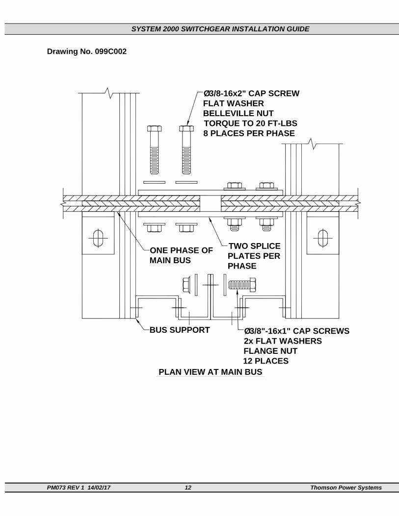
Drawing No. 099C002
MAIN BUSONE PHASE OF
BUS SUPPORT
8 PLACES PER PHASETORQUE TO 20 FT-LBSBELLEVILLE NUTFLAT WASHER
3/8-16x2" CAP SCREWØ
PHASEPLATES PERTWO SPLICE
12 PLACESFLANGE NUT2x FLAT WASHERS
3/8"-16x1" CAP SCREWSØ
PLAN VIEW AT MAIN BUS

SYSTEM 2000 SWITCHGEAR INSTALLATION GUIDE
PM073 REV 1 14/02/17 13 Thomson Power Systems
Drawing No. 099C003
MAIN BUSONE PHASE OF
BUS SUPPORT
8 PLACES PER PHASETORQUE TO 20 FT-LBSBELLEVILLE NUTSFLAT WASHERS
3/8-16x2.75" CAP SCREWSØ
PHASEPLATES PER(3) SPLICE
12 PLACESFLANGE NUT2x FLAT WASHERS
3/8"-16x1" CAP SCREWSØ
PLAN VIEW AT MAIN BUS

SYSTEM 2000 SWITCHGEAR INSTALLATION GUIDE
PM073 REV 1 14/02/17 14 Thomson Power Systems
Drawing No. 099C004
SUGGESTED BOLT LOCATIONS
Ø38"-16x1" CAP SCREWS
2x FLAT WASHERSFLANGE NUT12 PLACES
TYPICAL CROSS-SECTIONSERIES 2000 SWITCH GEAR
82.5
5436
57
33
7.5
BUS SECTIONCONTROL SECTION
90
180
0

SYSTEM 2000 SWITCHGEAR INSTALLATION GUIDE
PM073 REV 1 14/02/17 15 Thomson Power Systems
Drawing No. 099C005
24"
2.5"
2"
0.625"DIA.
36"36"
DETAIL 'A'
4" SILL CHANNELBASE (3/16" THICK STEEL)
PLAN VIEW OF BASE(TYPICAL)