read and understand all instructions and warnings prior to
TRANSCRIPT

021500, 021501 Page 1
491 W. Garfield Ave., Coldwater, MI 49036
Phone: 517-279-2135
Web/live chat: www.bds-suspension.com
E-mail: [email protected]
Read and undeRstand all instRuctions and waRnings pRioR to installation of system and opeRation of vehicle.
Part#: 021500, 021501Product: 5" suspension lift systemApplication: 1995-2004 chevrolet/gmc s10 ZR2 Blazer/Jimmy/pickup
safety waRning BDS Suspension Co. recommends this system be installed by a professional technician. In addition to these instructions, professional knowledge of disassembly/ reassembly procedures and post installation checks must be known.
pRoduct safety waRning Certain BDS Suspension products are intended to improve off-road perfor-mance. Modifying your vehicle for off-road use may result in the vehicle handling differently than a factory equipped vehicle. Extreme care must be used to prevent loss of control or vehicle rollover. Failure to drive your modified vehicle safely may result in serious injury or death. BDS Suspension Co. does not recommend the combined use of suspension lifts, body lifts, or other lifting devices.
You should never operate your modified vehicle under the influence of alcohol or drugs. Always drive your modified ve-hicle at reduced speeds to ensure your ability to control your vehicle under all driving conditions. Always wear your seat belt.
pRe-installation notes1. Special literature required: OE Service Manual for model/year of vehicle. Refer to manual for proper disassembly/
reassembly procedures of OE and related components.
2. Adhere to recommendations when replacement fasteners, retainers and keepers are called out in the OE manual.
3. Larger rim and tire combinations may increase leverage on suspension, steering, and related components. When selecting combinations larger than OE, consider the additional stress you could be inducing on the OE and related components.
4. Post suspension system vehicles may experience drive line vibrations. Angles may require tuning, slider on shaft may require replacement, shafts may need to be lengthened or trued, and U-joints may need to be replaced.
5. Secure and properly block vehicle prior to installation of BDS Suspension components. Always wear safety glasses when using power tools.
6. If installation is to be performed without a hoist, BDS Suspension Co. recommends rear alterations first.
7. Due to payload options and initial ride height variances, the amount of lift is a base figure. Final ride height dimensions may vary in accordance to original vehicle attitude. Always measure the attitude prior to beginning installation.
post-installation waRnings1. Check all fasteners for proper torque. Check to ensure for adequate clearance between all rotating, mobile, fixed, and
heated members. Verify clearance between exhaust and brake lines, fuel lines, fuel tank, floor boards and wiring harness. Check steering gear for clearance. Test and inspect brake system.
2. Perform steering sweep to ensure front brake hoses have adequate slack and do not contact any rotating, mobile or heated members. Inspect rear brake hoses at full extension for adequate slack. Failure to perform hose check/ replacement may result in component failure. Longer replacement hoses, if needed can be purchased from a local parts supplier.
3. Perform head light check and adjustment.
4. Re-torque all fasteners after 500 miles. Always inspect fasteners and components during routine servicing.
rev.4/26/2013
Page 2 021500, 021501
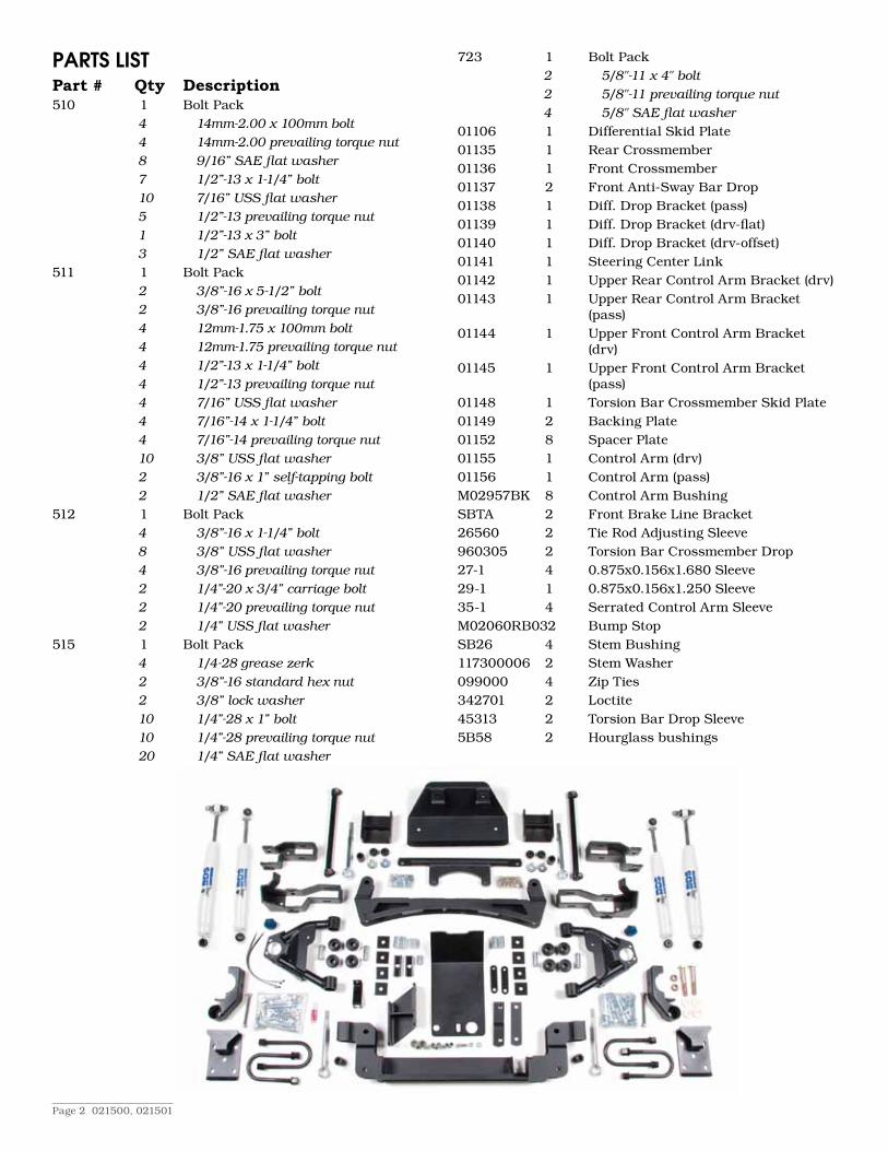
paRts listPart # Qty Description510 1 Bolt Pack
4 14mm-2.00 x 100mm bolt4 14mm-2.00 prevailing torque nut8 9/16”SAEflatwasher7 1/2”-13 x 1-1/4” bolt10 7/16”USSflatwasher5 1/2”-13 prevailing torque nut1 1/2”-13 x 3” bolt 3 1/2”SAEflatwasher
511 1 Bolt Pack2 3/8”-16 x 5-1/2” bolt2 3/8”-16 prevailing torque nut4 12mm-1.75 x 100mm bolt4 12mm-1.75 prevailing torque nut4 1/2”-13 x 1-1/4” bolt4 1/2”-13 prevailing torque nut4 7/16”USSflatwasher4 7/16”-14 x 1-1/4” bolt4 7/16”-14 prevailing torque nut10 3/8”USSflatwasher2 3/8”-16x1”self-tappingbolt2 1/2”SAEflatwasher
512 1 Bolt Pack4 3/8”-16 x 1-1/4” bolt8 3/8”USSflatwasher4 3/8”-16 prevailing torque nut2 1/4”-20 x 3/4” carriage bolt2 1/4”-20 prevailing torque nut2 1/4”USSflatwasher
515 1 Bolt Pack4 1/4-28greasezerk2 3/8”-16standardhexnut2 3/8”lockwasher10 1/4”-28 x 1” bolt10 1/4”-28 prevailing torque nut20 1/4”SAEflatwasher
723 1 Bolt Pack2 5/8"-11 x 4" bolt2 5/8"-11 prevailing torque nut4 5/8"SAEflatwasher
01106 1 Differential Skid Plate01135 1 Rear Crossmember01136 1 Front Crossmember01137 2 Front Anti-Sway Bar Drop01138 1 Diff. Drop Bracket (pass)01139 1 Diff. Drop Bracket (drv-flat)01140 1 Diff. Drop Bracket (drv-offset)01141 1 Steering Center Link01142 1 Upper Rear Control Arm Bracket (drv)01143 1 Upper Rear Control Arm Bracket
(pass)01144 1 Upper Front Control Arm Bracket
(drv)01145 1 Upper Front Control Arm Bracket
(pass)01148 1 Torsion Bar Crossmember Skid Plate01149 2 Backing Plate01152 8 Spacer Plate01155 1 Control Arm (drv)01156 1 Control Arm (pass)M02957BK 8 Control Arm BushingSBTA 2 Front Brake Line Bracket26560 2 Tie Rod Adjusting Sleeve960305 2 Torsion Bar Crossmember Drop27-1 4 0.875x0.156x1.680 Sleeve29-1 1 0.875x0.156x1.250 Sleeve35-1 4 Serrated Control Arm SleeveM02060RB03 2 Bump StopSB26 4 Stem Bushing117300006 2 Stem Washer099000 4 Zip Ties342701 2 Loctite45313 2 Torsion Bar Drop Sleeve5B58 2 Hourglass bushings

021500, 021501 Page 3
installation instRuctions1. Park and secure the vehicle on a level hard surface. Block the rear tires to avoid accidental movement.
2. Disconnect and remove the battery and battery tray. Disconnect the spring clip and remove the cable from the 4WD vacuum actuator. Disconnect the vacuum cable clamp at the frame. (Fig. 1)
Fig. 1
3. Raise the front of the vehicle so the tires are just off the ground. Support the vehicle with jack stands under the frame rail away from lower control arm anchors.
4. Remove the tires and wheels. Remove the skid plates and the front sway bar. Retain all hardware.
5. Measure the length of exposed thread on the torsion bar adjustment bolts and note below. Unload the torsion bars using #J36202 torsion bar unloading tool or equivalent. DS____ PS____
6. Mark the torsion bars for driver’s side (DS) front and passenger side (PS) front to ensure that they are installed as they were removed. Remove the torsion bars.
7. Mark the driver’s side tie rod assembly for inner and outer for future reference. Disconnect the tie rod ends from the OE knuckle and relay rod.
8. Disconnect the driver’s side (DS) inner C.V. joint from the differential flange by removing the fasteners on the older flange style. On newer model vehicles, pry the slip joint apart.
9. Disconnect the brake line and ABS lead from the upper control arm and retain fasteners. Unplug and dislodge the ABS lead from the frame. (Fig. 2)
Fig. 2

Page 4 021500, 021501
10. Remove the driver’s side brake caliper and support it out of the way. Do Not Let The Caliper Hang By The Hose!
11. Support the driver’s side lower control arm and knuckle assembly with a floor jack. Remove the upper control arm ball joint cotter pin and nut. Strike the knuckle near the ball joint to dislodge the ball joint or use a pickle fork. (Fig. 3)
Fig. 3
12. Disconnect the upper control arm pivot bolts and remove the upper control arm from the vehicle. Note the direction the bolts are installed.
13. Disconnect the shock. Disconnect the lower control arm pivot bolts and remove the knuckle/a-arm assembly from the vehicle.
14. Remove the front bump stops below the rear upper control arm pocket. (Fig. 4) These will be reused.
Fig. 4
15. Repeat the above for the passenger side. Remove stabilizer, if equipped, from fixed mount.
16. Remove the OE steering relay rod. (Fig. 5)

021500, 021501 Page 5
Fig. 5
17. Disconnect the front drive shaft from the differential and support it safely. Wrap tape over the u-joint cups of the trunion (U-joint cross). Do not allow the slider yoke to disengage from the shaft.
18. Support the differential with a floor jack. Disconnect the electrical connector and wire clip from the center of the differential. Disconnect the vent hose from the driver’s side of the differential. Disconnect the fasteners that attach the differential to the chassis and remove the differential from the vehicle.
Note:Whenloweringthefrontdifferential,makesurethattheactuatorcable(seeFig.1)doesnotbecomeentangled.
Note:Wedonotrecommendusingacuttingtorchforthefollowingstep.Useaplasmacutter,sawzall,orcut-offwheeltoremovemate-rialasinstructed.Besuretoalwayscheckbehindwhatyouarecuttingtoavoiddamage.Therearefuellinesinsidetheframeonthedriver’sside,sopleaseexercisecaution.Besuretoneverworkaloneandalwayskeepafireextinguisherhandy.
19. On the driver’s rear upper control arm pocket, cut the extended stop support wing off flush with frame. On the front surface of the pocket itself, make an outward 2” horizontal cut about 1/2” below the frame. Cut vertically through the bracket to meet the horizontal cut. (Fig. 6)
Fig. 6 - View from front - Dashes indicate cut path
20. On the back surface, start a cut flush with the bottom of the frame and cut upward about 3/4”. From that point cut horizontally outward about 2”. Cut again down the bracket to meet the horizontal cut. (Fig. 7)

Page 6 021500, 021501
Fig. 7 - View from back - Dashes indicate cut path
21. On the inside of rear upper A-arm pocket, there is a plate welded in place that protrudes into the pocket. This plate must be removed to create a flat internal service. (Fig. 8)
Fig. 8 - View from drivers side
22. Dress and paint the affected areas. Repeat steps 17-20 on the passenger’s side.
23. Cut off the inner portion of the driver’s side lower rear control arm pocket by making vertical and horizontal cuts 2” inward from the control arm mount holes. Dress and paint the affected area. (Fig. 9 & 10)
Fig. 9 - View from front - Dashes indicate cut path
Fig. 10 - View from back - Dashes indicate cut path

021500, 021501 Page 7
24. Cut the OE steering stabilizer mount off the back of the front crossmember behind the lower a-arm pocket. (Fig 11)
Fig. 11 - View from drivers side - Dashes indicate cut path
25. Install main rear crossmember (01135) in the lower rear control arm pockets with the open side facing the front of the vehicle. Attach using two 14mm x 100mm bolts, nuts, and 9/16” SAE washers from bolt pack #510. Leave hardware loose. (Fig. 12)
Fig. 12
26. Install the rear upper a-arm drop brackets (01142 DS & 01143 PS). Install the 1-11/16” sleeves inside the drop brackets and attach to the OE pocket using the 12mm x 100mm bolts, square spacer plates (01152), and nuts. (Bolt pack #511) Do not tighten at this time.
27. Align hole in drop bracket with the mating holes in the rear cross member. Attach drop bracket to cross member with the supplied 7/16” x 1-1/4” bolts, 3/8” USS washers and nuts from bolt pack #511.
28. Install OE bump stop on the bottom of the supplied a-arm drop brackets as they were removed.
29. Install a 1/2” x 1-1/4” bolt (Bolt pack #511) in a 01149 backing plate. Place bolt and plate in the frame so that the bolt threads are protruding out of the hole in the OE upper control arm pocket. Install the 01145 passenger’s side front upper a-arm bracket in the OE pocket by lining up the hole in the back of the bracket with the bolt in the frame. Secure it with a 1/2” nut and 1/2” SAE washer from bolt pack #511. Leave hardware loose. (Fig. 13)

Page 8 021500, 021501
Fig. 13
30. Repeat steps 27-30 on the driver’s side.
31. Install a 1/2” x 1-1/4” bolt, nut and 7/16” USS washers (Bolt pack #511) through the top of the OE pocket and new drop bracket. Leave loose. Insert the supplied 1-11/16” sleeve inside the bracket at the mounting point. Secure the bracket with a 12mm x 100mm bolt, nut (Bolt pack #511) and two 01152 spacer plates. Leave loose.
32. Install the front crossmember in the OE front lower control arm pockets (# 01136). Attach using two 14mm x 100mm bolts, nuts and 9/16” SAE washers (Bolt pack #510) from the rear to the front. Leave loose (Fig. 14).
Fig. 14
33. Using the holes in the crossmember as a template, drill out two 1/2” holes in the frame. Install two 1/2” x 1-1/4” bolts with nuts and 7/16” USS washers from bolt pack #510 to retain crossmember to the frame.
34. Install the driver’s side front differential mount using the straight bracket #01139 (outer) and the offset bracket #01140 (inner). Space brackets apart using the supplied 1-1/4” long sleeve. Loosely install the assembly using the 1/2” x 3” bolt, 7/16” USS washers and nut from bolt back #510. After installation, the offset hole in the offset drop bracket should be toward the front of the vehicle (Fig. 15).

021500, 021501 Page 9
Fig. 15
35. Loosely install passenger side differential drop bracket #01138. Use the two supplied 1/2” x 1-1/4” bolts with nuts and 7/16” USS washers from bolt pack #510 (Fig. 16).
Fig. 16
36. Mount differential to the supplied drop brackets. Attach the differential to the #01138 passenger’s side bracket using the OE fasteners. Attach the differential to the rear crossmember using the OE fasteners. Attach to the front driver’s side brackets using the OE fasteners. Torque all fasteners retaining the drop brackets to the chassis. Torque all fasteners retaining the drop brackets to the differential. 1/2" bolts torque to 65 ft.lbs., 7/16" bolts torque to 45 ft.lbs. Reconnect the electrical and vent lines to the differential.
37. Temporarily install the supplied dropped relay rod part #01141. Make a steering sweep checking clearance between the relay rod and the differential mount on the driver’s side. You will need to cut off the end of the pitman arm stud to gain clearance at the differential. If necessary loosen the differential mounting points and pull back to gain clearance. Tighten differential mounts to specification. You may also need to grind the differential mount to gain clearance. Do not remove excessive material from the differential mount!
38. Remove the center steering relay rod.

Page 10 021500, 021501
CONTROL ARM INSTALLATION39. If reusing the ball joints, they must be removed from the OE control arms. The ball joints will either be riveted or
bolted on. If riveted, remove the rivets with a grinder, drill, or air chisel.
40. Locate the new driver’s side control arm (Fig. 17).
Fig. 17
41. Install the ball joint (new or reused) in the new control arm using the 1/4” x 1” bolts, nuts, and SAE washers from bolt pack #515. Torque fasteners to 12 ft-lbs.
Note:Balljointinstallsfromthetopdown.
42. Install the new bump stop to the underside of the control arm cross brace and fasten with a 3/8” nut and 3/8” lock washer from bolt pack #515 (Fig. 18).
Fig. 18
43. Install the provided 1/4” grease zerks from bolt pack #515 in the two thread holes located on the top side of the control arm pivots (Fig. 19).
Fig. 19

021500, 021501 Page 11
44. Lubricate and install the provided fluted bushing in the control arms. Install the provided serrated steel sleeves in the bushings.
45. Mount the new control arm assembly into the frame bracket pockets and retain with the OE cam bolts (installed as they were removed). Do not tighten at this time.
46. With both upper control arms installed, go back and tighten all 1/2”, 7/16” and 12mm bolts that retain the upper control arm brackets to the frame and rear crossmember. Torque 1/2” hardware to 65 ft-lbs. Torque 7/16” and 12mm hardware to 50 ft-lbs.
Repeat the installation on passenger’s side of the vehicle47. Install the knuckle/a-arm assembly in the new brackets with the OE hardware while aligning the CV shaft to the
differential. Attach the upper control arm ball joint to the knuckle and torque upper ball joints to 61 ft.lbs. Leave a-arm pivot bolts loose.
48. After the lower a-arms are instlled, go back and tighten all of the fasteners retaining the front and rear crossmembers. Torque all 14mm and 1/2" fasteners to 65 ft.lbs. Torque all 7/16" fasteners to 45 ft.lbs. Do not install shock at this time. They must be installed after alignment.
49. Install the differential skid plate to the front and rear crossmember with 1/2” x 1-1/4” bolts and 1/2” SAE washer from bolt pack #510. Each of the three mounting points have nuts already attached.
50. Install the brake calipers to OE specification.
51. Connect the inner C.V. to the differential mating flange and torque flange bolts to specification. If installing a new slide in style, be sure the unit is fully engaged.
52. Relocate brake line mount on the frame by installing the supplied brake line relocation bracket #SBTA. Attach the supplied bracket to the OE mount using the OE fasteners. Carefully acquire slack in the brake lines. Manipulate the brake line outward and down to remount to the extension bracket using the 1/4” carriage bolt and nut from bolt pack #512.
53. Loosen the OE clamps that hold the ABS lead to the frame. Acquire sufficient slack in the frame lead to connect the sensor lead.
54. Attach the ABS wire bracket to the new control arm in the hole nearest to the ball joint using a 1/4” x 1” bolt, nut and SAE washers from bolt pack #515 (Fig. 19).
55. Attach the brake line bracket to the hole provided in the control arm using the OE bolt and nut (Fig 19).
56. Disconnect the tie rod ends from the OE relay rod and from the tie rod adjuster sleeves and install them on the supplied longer tie rod adjuster sleeves.
Note:thetierodendsareleftandrightthreaded.Besuretokeepthemseparated.Attachthenewadjustingsleeveassembliestothesuppliedrelayrodpart#01141andtightentospecification.Theadjustersleeveswiththetierodendsattachedshouldmeasureabout25.5”fromcenteroftierodendtocenteroftierodend.(Fig.20)
Fig. 20

Page 12 021500, 021501
57. Before installing the relay rod, be sure to check the idler and pitman arms, and replace if necessary. A worn idler arm can cause front end vibration. Install relay rod assembly in the vehicle. It is possible to install the relay rod backwards. Be sure the 3/4” thick plate welded to the round rod is facing down slightly forward. Torque the pitman and idler arm nuts to 81 ft.lbs. and install cotter pins. Attach the tie rods ends to the knuckles and torque all four nuts to 39 ft.lbs. and install cotter pins. Never loosen nuts to line up cotter pin hole, tighten more.
Note:Besurethattheclampsontheadjustersleevesarerotatedtothebottomtoincreaseclearancewiththedifferential.Completesteeringsweeptoinsureclearance.
58. Install the front sway bar drop brackets to the frame using the supplied 3/8” x 1-1/4” bolts, 3/8” USS washers, and nuts from bolt pack #512. Install brackets so they are open toward the center of the vehicle. Attach the sway bar to the drop brackets using the OE hardware. (Fig. 21)
Fig. 21
59. Attach the OE sway bar end links to the bottom of the lower control arm mounts. Torque bolts to 11 ft.lbs.
60. Install the torsion bars in the lower control arms and slide them forward about 12”.
61. Lower the torsion bar crossmember by installing the supplied 960305 extension links. First, install the supplied sleeve in to the new link bushing and attach using O.E. hardware. Torque the links to 50 ft-lbs. (Fig. 22)
Fig. 22
62. Install torsion bars in their original positions. Install indexers and torsion bars in the cross member.
63. Install torsion bar guard #01148. Install guard using the OE skid plate bolts in the thread crossmember holes. (Supplied 3/8” self-tapping bolts can also be used.) Place a 3/8” USS washer on the 3/8” x 5-1/2” bolt and start through the guard. Install a supplied blue bushing between the guard and the cross member. Run the bolt through the bushing and frame. Install a bushing and a stem washer on top of the 3/8” bolt sticking out the top and secure with the 3/8” nuts. Torque all 3/8” bolts to 30 ft.lbs. (Fig. 23) Hardware found in bolt pack #511.

021500, 021501 Page 13
Fig. 23
64. Reload the torsion bars using a #J36202 torsion bar tool or equivalent. Set the adjuster bolts to the original setting (See step 5). The setting may need adjustment to level the vehicle.
65. Relocate the vacuum actuator beneath the battery tray. Measure 1” toward the engine from each hole and mark. Drill a 5/16” hole at each mark and reattach the actuator with the OE bolts. If your actuator is faulty, contact 4x4 Posi-Lok for a replacement system: www.4x4 Posi-Lok or 517-279-7177.
66. Perform exhaust modification to clear the front driveshaft.
67. Install the front drive shaft.
68. Install wheels and tires. Torque nuts to 100 ft.lbs.
69. Lower vehicle to the ground and torque lower control arm bolts to 81 ft.lbs. and upper control arm D bolts to 85 ft.lbs.
70. Re-torque all fasteners. Check for full steering sweep. Check all brake lines for damage and clearance. Check to ensure proper clearance between all moving parts.
Note:Afterfrontendalignment,makesuretheadjustersleeveclampsarerotateddowntoaidindifferentialclearance.
Donotinstallfrontshocksuntilafterthefrontendalignmentiscomplete.
Rear Installation1. Block and secure the front of the vehicle. Use a hydraulic jack or equivalent to raise the rear of the vehicle. Place jack
stands under the frame just in front of the spring hangers.
2. Remove the wheels and tires. Remove the OE shocks.
3. Remove the retainer holding the brake line to the frame bracket. Slit the OE bracket to remove the brake line. Be sure not to damage the brake line. Bend the bracket open and remove the line. Bend the bracket back flat.
4. Install the supplied brake line drop bracket to the OE bracket using the supplied 3/8” x 1” bolt, nut and 3/8” USS washers from bolt pack #514. Attach the line to the key slot in the drop bracket.
5. Support the rear axle with a hydraulic jack. Disconnect the emergency brake cable guide from the frame.
Pick-up Only6. Disconnect the rear track bar at the frame mount by removing the OE bolt.
Blazer/Jimmy Only7. Disconnect the rear sway bar at the frame link mount. This is done by removing the nut that attaches the sway bar
to the link that comes down from the frame.
All Models8. Remove the spring U-bolts and remove the springs from the vehicle.
9. Clamp the leaf spring with two large c-clamps on both sides of the new center pin. Remove the center pin and insert it through the bottom of the spring. Tighten securely with OE nut.
10. Install the provided shock studs on the new spring perch brackets and retain with the provide nut and lock washer.

Page 14 021500, 021501
Pick-up Only11. The front of the passenger’s side OE spring perch must be modified. Remove the front tab of the OE perch to provide
clearance for the new BDS perch. (Fig. 24)
12. Install the new spring perch brackets on the axle tube. The long alignment tabs should fit in the rear of the OE axle perch. The shock mount should be facing the rear of the vehicle on the driver’s side and the front of the vehicle on the passenger’s side. The shock stud should point toward the center of the vehicle.
Note:Somemodelshaveabrakelinemountingbracketonthebackoftheaxletuberightwherethespringperchbracketmounts.Ifthisisthecase,theOEmountwillhavetobecutoff.Thesurfaceshouldbegroundflushandpainted.
Fig. 24
Blazer/Jimmy Only13. Install the new spring perch brackets on the axle tube. The long alignment tab should fit in the rear of the OE axle
perch. The shock mount should be facing the rear of the vehicle and the shock stud should point toward the center of the vehicle.
Note:Somemodelshaveabrakelinemountingbracketonthebackoftheaxletuberightwherethespringperchbracketmounts.Ifthisisthecase,theOEmountwillhavetobecutoff.Thesurfaceshouldbegroundflushandpainted.
All Models14. Lower the axle while taking care not to over-extend the brake lines or bind the drive shaft. Install the leaf springs on top
of the axle in the new perch brackets. Fasten the springs to the shackles and hanger with OE hardware. Do not tighten.
15. Install the new spring plate on top of the springs over the center pin with the bump stop pad toward the front of the vehicle. Install the new U-bolts around the axle and up through the new spring plate. Retain with provided high nuts and washers. Once both sides are installed and aligned torque the U-bolts to 100-120 ft-lbs. (Fig. 25)
16. Locate a safe location for the emergency brake guide. Drill a new hole and install using OE fasteners.
Fig. 25

021500, 021501 Page 15
Pick-up Only17. Install the supplied track bar drop bracket into the OE frame pocket. Fasten the bracket with 3/8” x 1” bolt, nut and
3/8” USS washers on the back of the bracket and a 1/2” x 2-1/2” bolt, nut and 1/2” SAE washers through the OE mounting hole. (Bolt pack #514) Torque 3/8" bolts to 35 ft.lbs. and 1/2" bolts to 90 ft.lbs.
Note:YoumayneedtodrillouttheOEholetoacceptthe1/2”bolt.
18. Install the wheels and tires and lower the vehicle to the ground.
19. Attach the track bar to the drop bracket with the OE fasteners. Do not tighten.
20. With thte weight of the vehicle on the tires torque the track bar mounting bolt to 45 ft.lbs.
Blazer/Jimmy Only21. Remove the factory sway bar links and save hardware. Install the supplied hourglass bushings and sleeves into
the new sway bar links. Attach the sway bar links to the axle and sway bar with the factory hardware and stem bushings.
All Models22. Install the supplied sleeve (3/4" O.D. x 1-3/8" long) in the lower bushing of the shock. Slide the 5/8" x 4" bolt
throught the mounting bracket so the nut end of the bolt is toward the center of the vehicle. Continue sliding on in the following order: 1-1/8" O.D. x 1-1/8" long spacer sleeve, 5/8" waher, shock, washer, and 5/8" nut. Tighten securely. (Fig. 26)
Note:Seeboltpack#723forallprovidedhardware.
23. Bounce the rear of the vehicle to settle the suspension. Torque the spring hanger and shackle bolts to OE specs.
24. Check all fasteners for proper torque.
Fig. 26
For questions, technical support and warranty issues relating to this BDS Suspension product, please contact your dis-tributor/installer before contacting BDS Suspension directly.
Sold/Installed by:
notice to dealeR/installeRThese instructions, the warning card, and included decals must be given to the owner of this BDS Suspension product.