reactivity controlled compression ignition (rcci) for high … · 2016-11-09 · 1 engine research...
TRANSCRIPT

1 Engine Research Center, 2016
Reactivity Controlled Compression Ignition (RCCI)
for high-efficiency clean IC engines
Prof. Rolf D. Reitz
Engine Research Center,
University of Wisconsin-Madison
Aurel Stodola Lecture
Department of Mechanical and Process Engineering of ETH Zurich
Wednesday, November 9th, 2016
Acknowledgements:
Industry Partners:
Direct-injection Engine Research Consortium members,
Caterpillar, Ford, General Motors.
Sandia, Argonne, Oak Ridge National Labs,
ARO, DOE, NASA, ONR, Princeton CEFRC.
- ERC faculty, staff and students

UW-Madison
Founded in 1848 (land-grant institution). 42,600 students; 2,000 facultyRanked No. 2 US public university
~ $1 billion/year in research funding
Engine Research CenterLargest academic research center focusing
on IC engines in the US
~ $4-5M annual research budget
~ 8 Faculty, 55 graduate students,
10-15 research staff, post doc/visiting scholars
Mechanical Engineering35 faculty, 7 instructional staff
- 543 undergraduates
- 170 graduate students
~$10 million in research annually
2 Engine Research Center, 2016

Engine Research Center
3
Myers BormanUyehara
Founded in 1946 ARO Center of Excellence; DOD DOE; Consortia/Industry
2-color soot radiation,
droplet experiments
0-D engine simulation,
heat release analysis
1985 - 2003
First to demonstrate HCCI in a 4-stroke engine
First to demonstrate benefits of multiple injections for power and emissions
Pioneered Multi-Dimensional modeling for concept evaluation
Advanced spray/combustion diagnostics for fuel-air mixing and emissions characterization
In-cylinder gaseous species measurement, high resolution spray analysis
High-fidelity engine codes, detailed chemistry for emission prediction, spray & turbulence modeling
Control strategies, HCCI/RCCI
Combustion system optimization
Aftertreatment experiments and modeling
2003 +
Engine Research Center, 2016
Emeritus faculty
Mario Trujillo Sage KokjohnScott Sanders
ERC faculty

Outline
4 Engine Research Center, 2016
• Motivation for investigating Internal Combustion (IC)
engine efficiency
• Requirements for high-efficiency, clean combustion
• Engine combustion modeling and optimization
background
• Reactivity Controlled Compression Ignition (RCCI):
- pathway to high-efficiency clean combustion using in-cylinder
blending of fuels with different auto-ignition characteristics
• Performance of RCCI combustion
• Limits and practical applications of RCCI
• New concepts
• Conclusions and future research directions

Why research IC engine efficiency?
5 Engine Research Center, 2016
Internal combustion (IC) engines are the work horses of transportation and
power generation
70% of all crude oil consumed is used to fuel IC engines
Improvements in engine efficiency can have a major impact on fossil fuel
consumption and green house gas (GHG) emissions on a global scale
IC engines are expected to be the dominant (>90%) prime mover for
transportation applications well into the future1,2,3
Many open questions:4
- what combustion process should future IC engines utilize?
- what fuels are best suited for high efficiency combustion?
- how can renewable and alternative fuel sources be utilized most
effectively?
1Quadrennial Technology Review, DOE 20112Review of the Research Program of the FreedomCAR and Fuel Partnership: 3rd
Report, NRC 2010 3Energy Information Agency, Annual Energy Outlook 2012, June 2012. 4Reitz, R.D., “Directions in Internal Combustion Engine Research,” CNF, 160, 2013.
Engine Research Center, 20166
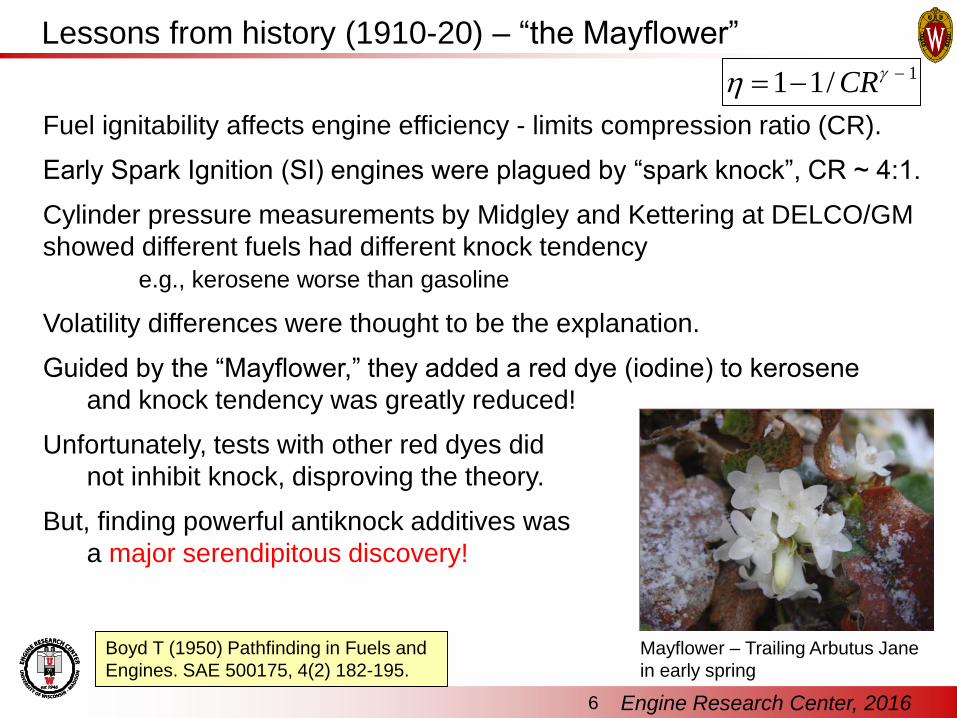
Boyd T (1950) Pathfinding in Fuels and
Engines. SAE 500175, 4(2) 182-195.
Fuel ignitability affects engine efficiency - limits compression ratio (CR).
Early Spark Ignition (SI) engines were plagued by “spark knock”, CR ~ 4:1.
Cylinder pressure measurements by Midgley and Kettering at DELCO/GM
showed different fuels had different knock tendency
e.g., kerosene worse than gasoline
Volatility differences were thought to be the explanation.
Guided by the “Mayflower,” they added a red dye (iodine) to kerosene
and knock tendency was greatly reduced!
Unfortunately, tests with other red dyes did
not inhibit knock, disproving the theory.
But, finding powerful antiknock additives was
a major serendipitous discovery!
Mayflower – Trailing Arbutus Jane
in early spring
Lessons from history (1910-20) – “the Mayflower”1/11 CR

Engine Research Center, 20167
Research after WW-I was motivated by national security - Improved fuel efficiency with higher CRs made possible the first
non-stop airplane flight from New York to San Diego in the 1920’s.
GM and US Army studied hundreds of additives and found aromatic
amines to be effective knock suppressors.
1920 experimental GM car driven on gasoline with toluidine with CR ~7:1 - 40% better fuel consumption than 4:1.
Engine exhaust plagued by unpleasant odors
Lessons from history (1920-30) – the Amines and TEL
Reitz, Front. Mech. Eng. 1:1, 2015
Much research was devoted to find acceptable additives, - finally leading to tetraethyl lead (TEL)
But, TEL caused solid deposits, damaged exhaust valves and spark plugs.
Scavenger additives with bromine and chlorine corrected the problem.- Partnership with Ethyl-Dow and DuPont to extract compounds from sea water
- 10 tons of sea water needed to provide 1 lb of bromine!
- “the goat”!
WW-II aviation engines used iso-heptane (triptane: 2,2,3-trimethyl butane) - allowed CR as high as 16:1.

Engine Research Center, 20168
Lead poisoning was an early concern - In 1926 US Surgeon General determined that TEL poses no health hazards.
- Use of lead in automotive fuels has been called “The mistake of the 20th century”
1950: Dr. Arie Haagen-Smit - cause of smog in LA to be HC/NO - Cars were the largest source of UHC/NOx
1950: Eugene Houdry - developed catalytic converter for auto exhaust. - But, lead was found to poison catalytic converters.
20 years later: US EPA announces gas stations must offer "unleaded" gasoline,
- Based accumulated evidence of negative effects of lead on human health.
- Leaded gasoline was still tolerated in certain applications (e.g., aircraft),
but was permanently banned in the US in 1996, in Europe since 2000
Lessons from history (1930-70) –TEL and the future
Reitz, Front. Mech. Eng. 1:1, 2015
World Wars & national security played a major role to define automotive fuels.
Today’s engines and their fuels would not have been developed without
close collaboration between engine OEMs, energy and chemical companies!
A consequence of collaboration between “big” engine and “big” oil is that
transformative changes in transportation systems will not occur easily.
A new concept engine must be able to use available fuels,
A new fuel must run in existing engines.

Maximizing engine efficiency
• Fuel energy is wasted due to:
– Incomplete combustion (i.e.,
combustible material flowing out
the exhaust)
– Heat transfer losses to the
coolant, oil, and air
– Unrecovered exhaust energy
– Pumping losses
– Friction losses
• Goal is to maximize Brake
Thermal Efficiency
• Diesel engines have more
than 10% higher thermal
efficiency than Spark-Ignited
engines
9 Engine Research Center, 2016
CAFE
On July 29,
2011
President
Obama
announced an
agreement
with 13 large
automakers to
increase fuel
economy to
54.5 miles per
gallon for cars
and light-duty
trucks by
model year
2025
Sankey diagram

Diesel emissions regulations
US Environmental
Protection AgencyEuropean Union
After-treatment: considerable expense and complexity – VW scandal!
In addition to increasing fuel efficiency, stringent mandates must be met.
10 Engine Research Center, 2016

11 Engine Research Center, 2016
Advanced diesel combustion
Conventional diesel Low temperature H/PCCI
• High EGR to reduce temperature,
early injection to improve mixing
• Low NOx and soot emissions
• Start of combustion controlled by
by fuel chemistry
- limits engine load (less power)
• Combustion timing and heat
release controlled by injection
• High NOx and soot emissions
Sandia Cummins
N14 optical engine
HCCI

12 Engine Research Center, 2016
Advanced diesel combustion
Conventional diesel Low temperature H/PCCI
• High EGR to reduce temperature,
early injection to improve mixing
• Low NOx and soot emissions
• Start of combustion controlled by
by fuel chemistry
- limits engine load (less power)
• Combustion timing and heat
release controlled by injection
• High NOx and soot emissions
Sandia Cummins
N14 optical engine
HCCI

Engine combustion optimization via CFD modeling
Engine combustion physics occurs over an
immense range of time and length scales
Unique modeling challenge that includes
virtually all aspects of mechanical engineering
- Turbulence
- Combustion
- Two-phase flow
Chemistry of real fuels involves 100’s of
species and 1000’s of reactions
Bore
diameter
Turbulence-
chemistry
interactions
10-2 10-6 10-9
Soot
Inception
10-3 10-6 10-9
Engine
Cycle
Fluid flow Chemistry
Length Scale [m]
Time Scale [s]
Ideally all scales would be resolved considering all species and reactions with
Direct Numerical Simulation (DNS) and detailed chemistry
single engine cycle would take decades
Engineering applications must model:
Small scales of turbulence (RANS or LES)
Turbulent combustion (average species production)
Chemical kinetics (reduced, but representative chemistry)
In current practical CFD models all scales of turbulence are typically
modeled (Reynolds Averaged Navier-Stokes (RANS)) and combustion is
modeled using direct-integration of a reduced chemical kinetics mechanism
13 Engine Research Center, 2016

14 Engine Research Center, 2016
UW-ERC Multidimensional CFD modelsSubmodel Los Alamos UW-Updated References
intake flow assumed initial flow compute intake flow SAE 2011-01-0821
heat transfer law-of-the-wall compressible, unsteady E&F 2012
turbulence standard k- RNG k- /LES SAE 2011-01-0829
nozzle flow none cavitation modeling SAE 2011-01-0386
atomization Taylor Analogy surface-wave-growth SAE 960633
Kelvin Hemholtz SAE 980131
Rayleigh Taylor CST 171, 1998
drop breakup Taylor Analogy Rayleigh Taylor AAS 6, 1996
drop drag rigid sphere drop distortion SAE 960861
wall impinge none rebound-slide model SAE 880107
wall film/splash SAE 982584
collision/coalesce O’Rourke shattering collisions AAS 19, 2009
vaporization single component multicomponent fuels IJMF 35, 2009
low pressure high pressure IJHMT 45, 2002
ignition Arrhenius reduced chemistry CNF 158, 2011
combustion Arrhenius CTC/GAMUT SAE 2004-01-0102
Sparse matrix/cluster SAE 2012-01-1974
NOx Zeldo’vich GRI reduced SAE 2008-01-2413
soot none 2-Step formation/oxidation IJTS 48, 2009
PAH/Multi-step phenomen. CST 182, 2010
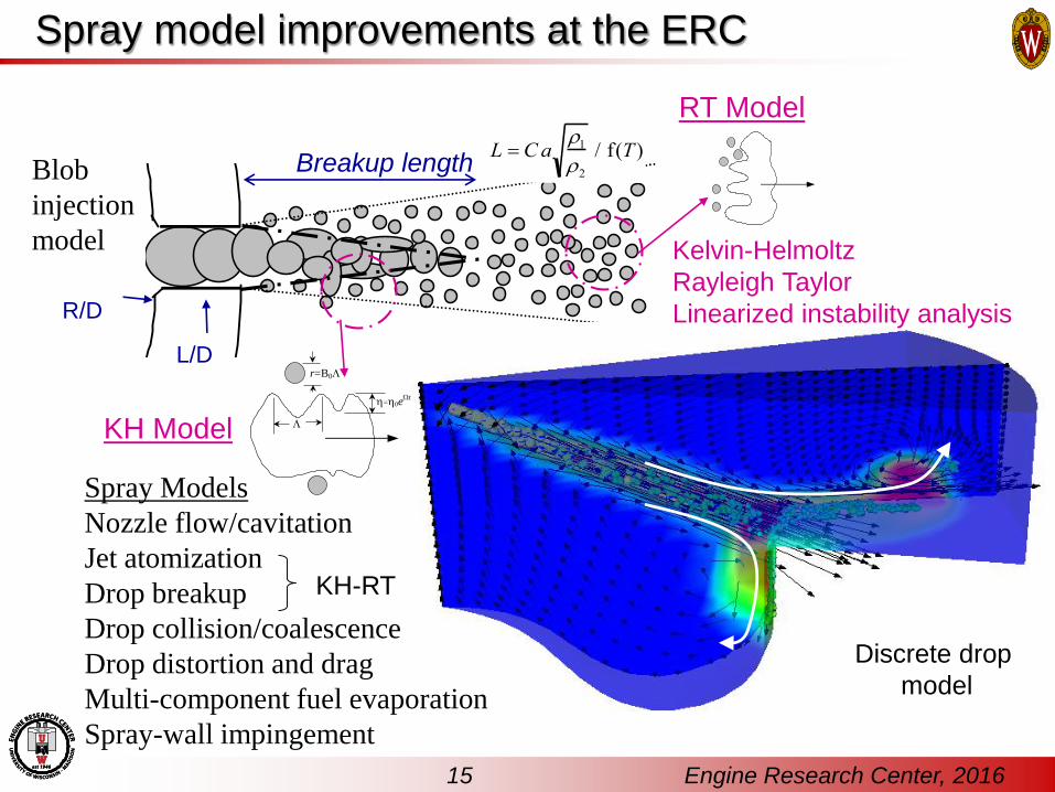
R/D
L/D
Breakup lengthL Ca
12/ f(T )
Blob
injection
model
Spray model improvements at the ERC
Discrete drop
model
=0et
r=B0
KH Model
RT Model
Kelvin-Helmoltz
Rayleigh Taylor
Linearized instability analysis
KH-RT
Spray Models
Nozzle flow/cavitation
Jet atomization
Drop breakup
Drop collision/coalescence
Drop distortion and drag
Multi-component fuel evaporation
Spray-wall impingement
15 Engine Research Center, 2016

16 Engine Research Center, 2016
Surrogate fuels - 18 component model
alkanes
aromatics
cycloalkanes
PAH
corrected
DMC vaporization model: Diesel, Jet-A, JP-8

Fuel property and chemistry surrogates
Cyclo alkanes
n-alkane
n-alkane
iso-alkanes
Aromatics
cyclohexane
decalin cyclohexane
n-dodecane
n-heptane
n-octadecane
n-tetradecane
naphthalene
mcymene
tetralin
n-pentylbenzene
n-heptylbenzene
toluene
heptamethyl nonane
tetramethyl hexane
iso-octane
Physical property
surrogates
Chemistry
surrogates
Chemical class grouping – MultiChem skeletal mechanism
25 species
51 reactions
857 species
3586 reactions
LLNL detailed
mechanismERC reduced
mechanism*
* Ra and Reitz, Combustion & Flame 2011
Mu
ltiC
he
mM
ech
an
ism
10
0 s
pe
cie
s, 3
48
re
actio
ns
17 Engine Research Center, 2016
Primary Reference Fuels

6 bar IMEP
0 10 20 30 40 50 600
20
40
60
80
100
250
180 g/kW-hr
MISFIRE
190
g/kW-hr
PR
F [-]
EGR Rate [%]
10
bar/deg.
5.6
bar/deg.
Combustion optimization - fuel and EGR selection
HCCI simulations used to choose
optimal EGR rate and PRF
(isooctane/n-heptane) blend
at 6, 9, and 11 bar IMEP, 1300 rpm
Predicted contours agree well
HCCI experiments
As load is increased the minimum
ISFC cannot be achieved with
neat diesel or neat gasoline
0 10 20 30 40 50 600
20
40
60
80
100
190 g/kW-hr
180 g/kW-hr
PR
F [-]
EGR Rate [%]
10 bar/deg.
0 10 20 30 40 50 600
10
20
30
40
50
60
70
80
90
100
24 bar/deg
28 bar/deg
160
MISFIRE
190 g/kW-hr
170 g/kW-hr
180 g/kW-hr
PR
F
EGR Rate [%]
170
190
210
230
240
200
Net ISFC
[g/kW-hr]
9 bar IMEP
0 10 20 30 40 50 600
20
40
60
80
100
16
bar/deg.
230
220
180
MISFIRE
210
190
200
PR
F [-]
EGR Rate [%]
11 bar IMEP
EGR Rate [%]
PR
F
Kokjohn, SAE 2009-01-2647
Gasoline-diesel
“cocktail”
Gasolin
eD
iesel
18 Engine Research Center, 2016

KIVA CFD plus Genetic Algorithm optimization used to choose injection parameters
- Gasoline (I-C8H18)
- Diesel (n-C7H14)
Fuel reactivity and EGR from
HCCI investigation (9 bar IMEP)
Global PRF = 65
EGR rate = 50%
80% gasoline/20% diesel
- SOI1 ~ -60°ATDC
- SOI2 ~ -33°ATDC
- 60% of diesel fuel
in first injection
-25 -20 -15 -10 -5 0 5 10 15 201E-6
1E-5
1E-4
1E-3
0.01
oh
HRR
Temp
ch2o
conc7h16
c14h30
ic8h18
ch2o
oh
co
(J/Deg)
(K)
Crank [ATDC]
Mass F
raction [-]
ic8h18
0
200
400
600
800
1000
1200
1400
1600
HR
R [J/
] and A
vera
ge T
em
pera
ture
[K
]
Gasoline
Diesel
Controlled combustion
timing and duration
Charge preparation optimization
Kokjohn, SAE 2009-01-2647
Kokjohn & Reitz ICLASS 2009
Premixed and Direct Injected fuel blending

Direct injected diesel
Port injected gasoline
-80 to -50 -45 to -30
Crank Angle (deg. ATDC)
Inje
cti
on
Sig
nal Squish
Conditioning
Ignition
Source
Gasoline
Optimized Reactivity Controlled Compression Ignition (RCCI)
Optimized fuel blending in-cylinder
Gasoline Diesel
Diesel
Kokjohn, SAE 2009-01-2647
20 Engine Research Center, 2016
Replace Diesel Exhaust Fluid (DEF) with widely available fuel

Heavy- and light-duty ERC experimental engines
Engine Heavy Duty Light Duty
Engine CAT SCOTE GM 1.9 L
Displ. (L/cyl) 2.44 0.477
Bore (cm) 13.72 8.2
Stroke (cm) 16.51 9.04
Squish (cm) 0.157 0.133
CR 16.1:1 15.2:1
Swirl ratio 0.7 2.2
IVC (°ATDC) -85 and -143 -132
EVO(°ATDC) 130 112
Injector type Common rail
Nozzle holes 6 8
Hole size (µm) 250 128
LDHD
Engine size scaling
Staples, SAE
2009-01-1124
21 Engine Research Center, 2016
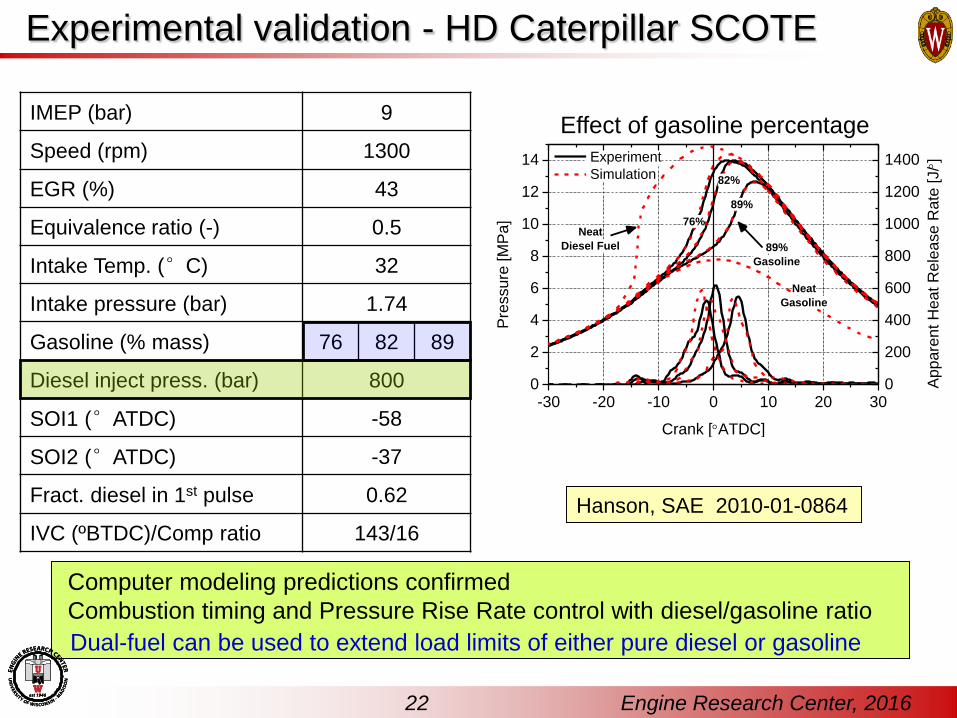
IMEP (bar) 9
Speed (rpm) 1300
EGR (%) 43
Equivalence ratio (-) 0.5
Intake Temp. (°C) 32
Intake pressure (bar) 1.74
Gasoline (% mass) 76 82 89
Diesel inject press. (bar) 800
SOI1 (°ATDC) -58
SOI2 (°ATDC) -37
Fract. diesel in 1st pulse 0.62
IVC (ºBTDC)/Comp ratio 143/16
Computer modeling predictions confirmed
Combustion timing and Pressure Rise Rate control with diesel/gasoline ratio
Effect of gasoline percentage
Hanson, SAE 2010-01-0864
-30 -20 -10 0 10 20 300
2
4
6
8
10
12
14 Experiment
Simulation
Crank [ATDC]
Pre
ssu
re [M
Pa
]
0
200
400
600
800
1000
1200
1400
89%
Gasoline
76%
82%
89%
App
are
nt H
ea
t R
ele
ase
Ra
te [J/]
Neat
Gasoline
Neat
Diesel Fuel
Dual-fuel can be used to extend load limits of either pure diesel or gasoline
Experimental validation - HD Caterpillar SCOTE
22 Engine Research Center, 2016

4 6 8 10 12 14 16
4548515457
0.00
0.01
0.02
0.030.0
0.1
0.2
0.3
Heavy-duty RCCI (gas/gas+3.5% 2-EHN, 1300 RPM)Heavy-duty RCCI (E-85/Diesel, 1300 RPM)Heavy-duty RCCI (gas/diesel 1300 RPM)
Gro
ss
Ind
.E
ffic
ien
cy
Gross IMEP [bar]
So
ot
[g/k
W-h
r]
HD Target (~2010 Levels)
NO
x[g
/kW
-hr]
HD Target (~2010 Levels)
RCCI – high efficiency, low emissions, fuel flexibility
Splitter, SAE 2010-01-2167; Hanson, SAE 2011-01-0361
Indicated efficiency of 58±1%
achieved with E85/diesel
Emissions met in-cylinder,
without need for after-treatment
Considerable fuel flexibility,
including ‘single’ fuel operation
23 Engine Research Center, 2016
Diesel can be replaced with
<0.5% total cetane improver
(2-EHN/DTBP) in gasoline
- less additive than SCR DEF
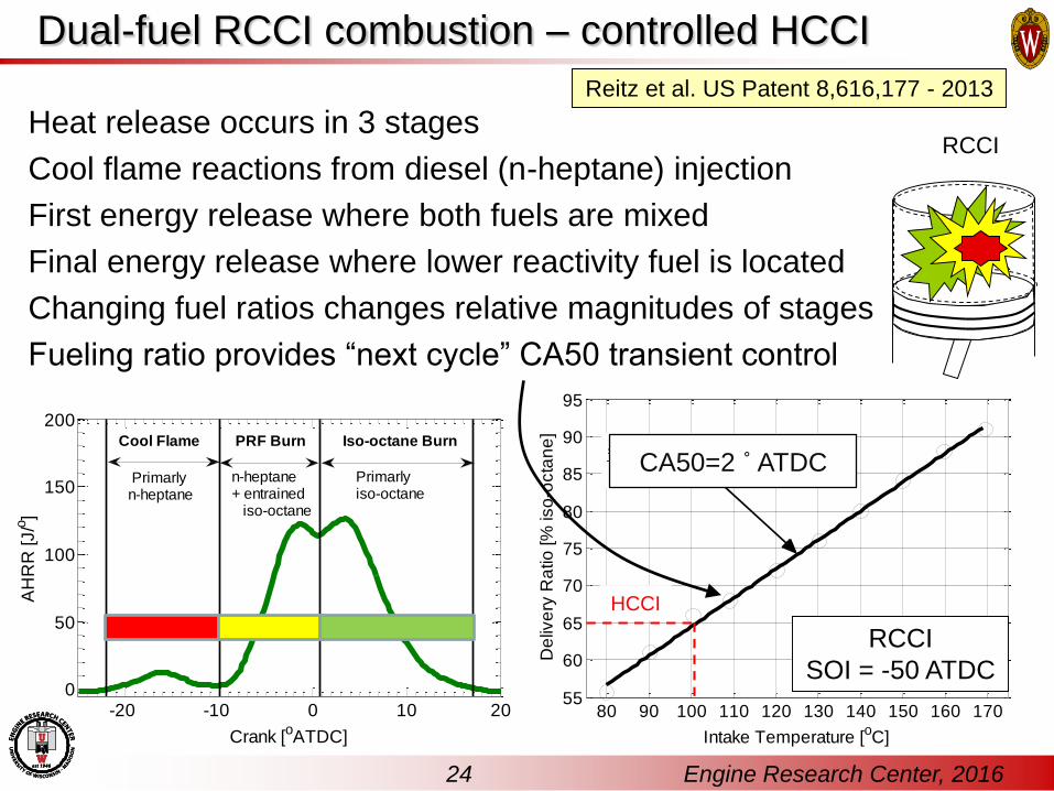
Dual-fuel RCCI combustion – controlled HCCI
Heat release occurs in 3 stages
Cool flame reactions from diesel (n-heptane) injection
First energy release where both fuels are mixed
Final energy release where lower reactivity fuel is located
Changing fuel ratios changes relative magnitudes of stages
Fueling ratio provides “next cycle” CA50 transient control
24
-20 -10 0 10 200
50
100
150
200
Crank [oATDC]
AH
RR
[J/o
]
Primarly iso-octane
n-heptane+ entrained iso-octane
Iso-octane BurnPRF BurnCool Flame
Primarly n-heptane
80 90 100 110 120 130 140 150 160 17055
60
65
70
75
80
85
90
95
Intake Temperature [oC]
De
live
ry R
atio
[%
iso
-octa
ne
]
CA50=2 ˚ ATDC
RCCI
SOI = -50 ATDC
RCCI
Reitz et al. US Patent 8,616,177 - 2013
24 Engine Research Center, 2016
HCCI

Model validation via RCCI optical experiments
RCCI experiments in Sandia HD
optical engine
LED illumination through side windows
to visualize sprays
Images recorded through both piston-
crown and upper window
Crank-angle-resolved high-
temperature chemiluminescence
with high-speed CMOS camera
Short-wave pass filter to reject long-
wavelength (green through IR) soot
luminosity
Engine Cummins N-14
Bore x stroke 13.97 x 15.24 cm
Displacement 2.34 L
Geometric compression ratio 10.75
GDI
Iso-octane
100 bar
7x150 micron
Common-rail
n-heptane
600 bar
8x140 micron
Inc. Ang. 152°Kokjohn, SAE 2012-01-0375
25 Engine Research Center, 2016

26 Engine Research Center, 2016Bowl window Squish (upper) window
Load: 4.2 bar IMEP GDI SOI: -240°ATDC
Speed: 1200 rpm CR SOI: -57°/-37° ATDC
Intake Temperature: 90° C Equivalence ratio: 0.42
Intake Pressure: 1.1 bar abs. Iso-octane mass %: 64
Kokjohn, ILASS-2011
RCCI combustion luminosity imaging

27 Engine Research Center, 2016
Computational Optimization of RCCI
SAE 2011-24-0015

28 Engine Research Center, 2016
• Sharp end-of-combustion
• Peak temperatures reduced
significantly compared to
conventional diesel combustion
• Difference between peak and
average temperatures very small
for RCCI combustion
– Well mixed combustion event-20 -15 -10 -5 0 5 10 15 20 25 300
20
40
60
80
100
120
140
+4
TDC
-4
-8-12
-16
RCCI
Diesel
Crank [ATDC]
Pre
ssu
re [
bar]
Diesel SOI
Retard
-20
0
300
600
900
1200
1500
Hea
t R
ele
as
e R
ate
[J
/]
-20 -15 -10 -5 0 5 10 15 20 25 30600
900
1200
1500
1800
2100
2400
2700
+4
TDC
-4
-8
-12
-16
RCCI
Diesel
Crank [ATDC]
Pe
ak
Te
mp
era
ture
[K
]
-20
-20 -15 -10 -5 0 5 10 15 20 25 30600
900
1200
1500
1800
2100
2400
2700
+4TDC-4-8
-12-16
RCCI
Diesel
Crank [ATDC]
Avera
ge T
em
pera
ture
[K
]
-20
Comparison of conv. diesel and RCCI - KIVA CFD
9 bar IMEP,
1300 rpm,
41% EGR

29 Engine Research Center, 2016
Temperature contours near CA50, Crank = 6.1 deg ATDC
Comparison of conv. diesel and RCCI combustion
• High temperature in conventional diesel next to piston bowl surface
• Highest temperature for RCCI in center of chamber (adiabatic core)
• Region near liner has similar temperatures
– heat transfer differences are at piston bowl surface

30 Engine Research Center, 2016
RCCI
(800 bar)
High-EGR
Diesel
(1800 bar)
Ringing (MW/m2) 3.8 2.8
Max PRR (bar/deg) 10.3 8.9
Gross Indicate TE (%) 54.3 48.5
Combustion Loss (%) 1.3 0.7
ISNOx (g/kW-hr) 0.006 0.97
ISsoot (g/kW-hr) 0.01 0.1
48.557.9
19.2 10.9
31.641.5 33.4 38.1
61.954.3
0
10
20
30
40
50
60
70
80
90
100
With HT Adiabatic With HT Adiabatic
High-EGR Diesel RCCI
Fu
el E
nerg
y [
%]
Comb. LossExhaustHeat LossGIE
Comparison of conv. diesel and RCCI - KIVA CFD
RCCI:
- Similar pressure rise rates
- Significantly lower NOx and soot
- 16% higher thermal efficiency
- Reduced heat losses (~50%)
- Improved end-of-combustion phasing
SOI -12o
-10 -5 0 5 10 15 20 25
39
42
45
48
51
54
57
RCCI
High EGR Diesel Pinj 800 bar
High EGR Diesel Pinj 1800 bar
RCCI Combustion
SOI -20ATDC
CA50 [ATDC]
Gro
ss In
dica
ted
Eff
icie
ncy
[%]
7% of
fuel energy

Pancake 18.7:1 piston design
~1.2 less surface area
GT-Power heat transfer HX tuned to
match data
- 14.9:1 piston required HX = 0.4
- 18.7:1 required HX = 0.3
- without oil cooling, HX = 0.2
GTE
(%)
IMEPg
(bar)
NTE
(%)
IMEPn
(bar)
Experiment 59.1 6.82 55.0 6.27
Model, HX =0
100% comb. η62.4 7.12 58.5 6.85
Model, HX =0
100% comb.η,
0% EGR
63.4 7.23 61.0 6.95
94% of maximum theoretical cycle efficiency achieved !
-40 -30 -20 -10 0 10 20 30 40-15
0
15
30
45
60
75
90
105
120
135
150
E85 / 3% EHN+91 PON RCCI
43C intake, 42% EGR,
6.3 bar IMEPn
EXP, Squirter off, 43% EGR, Oil Matrix Point 83
GTPower, HX=0, 100% comb. , 43% EGR
GTPower, HX=0, 100% comb. , 0% EGR
Pre
ss
ure
(b
ar)
Crank Angle (CA ATDC)
0
150
300
450
600
750
AH
RR
(J
/ C
A)
Splitter et al. “RCCI Engine Operation Towards 60% Thermal Efficiency”, SAE 2013-01-0279
31 Engine Research Center, 2016
Ultra high efficiency, dual fuel RCCI combustion
DI: 3%EHN+91ON
PFI: E85
TIVC = 43 C
EGR = 42%
16.1
14.918.7

32 Engine Research Center, 2016
GM 1.9L Engine Specifications
Multi-cylinder RCCI - transient operation, open/closed loop control
Engine Type EURO IV Diesel
Bore 82 mm
Stroke 90.4 mm
Displacement 1.9 liters
Cylinder
Configuration
Inline 4
4 valves per cylinder
Swirl Ratio Variable (2.2-5.6)
Compression
Ratio 17.5
EGR SystemHybrid High/Low
Pressure, Cooled
ECU (OEM) Bosch EDC16
ECU (new) Drivven
Common Rail
Injectors
Bosch CRIP2-MI
148° Included Angle
7 holes,
440 flow number.
Port Fuel
Injectors
Delphi
2.27 g/s steady flow
400 kPa fuel pressure
UW RCCI Hybrid Vehicle
SAE 2015-01-0837
Highway Fuel Economy Testing of an RCCI Series Hybrid VehicleReed Hanson, Shawn Spannbauer, Christopher Gross, Rolf D. Reitz, University of Wisconsin; Scott Curran, John Storey, Shean Huff, ORNL

Engine Research Center, 201633
. UDDS/FTP cycle
RCCI offers diesel-like or
better BTE across speed-load range
ORNL simulations indicate RCCI
offers >20% fuel economy c.f.
2009 PFI engines
Wagner, Aramco
Workshop, 2014
ERC/ORNL Collaboration - RCCI - vehicle operation

RCCI Emissions
34 Engine Research Center, 2016
ORNL experiments indicate that > 95% of the PM in RCCI is condensed organic hydrocarbons.

RCCI low particle number – by 2 orders of magnitude
35 Engine Research Center, 2016

Collaboration with Oak Ridge – GM 1.9L Multi-cylinder engine
SAE 2010-01-2266
36 Engine Research Center, 2016

Operating Condition Low-
Load
Mid-Load High-Load
Gross IMEP [bar] 4 9 11 13.5 16 23
Engine Speed [rpm] 800 1300 1370 1460 1550 1800
Intake Press. [bar abs.] 1.00 1.45 1.94 2.16 2.37 3.00
Intake Temp. [°C] 60 60 60 60 60 60
Caterpillar 3401E SCOTE
Displacement [L] 2.44
Bore x Stroke [mm] 137.2 x 165.1
Con. Rod Length [mm] 261.6
Compression Ratio 16.1:1
Swirl Ratio 0.7
IVC [deg ATDC] -143
EVO [deg ATDC] 130
Common Rail Diesel Fuel Injector
Number of Holes 6
Hole Diameter [μm] 250
Included Spray Angle 145o
Design Parameter Minimum Maximum
Premixed Methane [%] 0% 100%
DI Diesel SOI 1 [deg ATDC] -100 -50
DI Diesel SOI 2 [deg ATDC] -40 20
Diesel Fraction in First Inj. [%] 0% 100%
Diesel Injection Pressure [bar] 300 1500
EGR [%] 0% 60%
Natural gas/diesel RCCI
ERC KIVA PRF kinetics
NSGA-II MOGA
32 Citizens per generation
~9500 Cells @ BDC
UW Condor -
Convergence after ~40 genrtns
37 Engine Research Center, 2016
Nieman, 2012RCCI Fuel flexibility – Alternative fuels
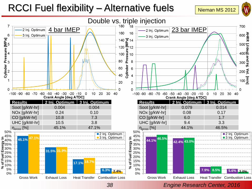
Double vs. triple injection
Results 2 Inj. Optimum 3 Inj. Optimum
Soot [g/kW-hr] 0.004 0.004
NOx [g/kW-hr] 0.24 0.10
CO [g/kW-hr] 10.8 7.3
UHC [g/kW-hr] 10.5 3.8
ηgross [%] 45.1% 47.1%
4 bar IMEP 23 bar IMEP
Results 2 Inj. Optimum 3 Inj. Optimum
Soot [g/kW-hr] 0.079 0.014
NOx [g/kW-hr] 0.08 0.17
CO [g/kW-hr] 6.0 1.7
UHC [g/kW-hr] 9.4 3.3
ηgross [%] 44.1% 46.5%
44.1% 42.4%
7.9% 5.6%
46.5%43.0%
8.5% 2.0%0%
5%
10%
15%
20%
25%
30%
35%
40%
45%
50%
Gross Work Exhaust Loss Heat Transfer Combustion Loss
% o
f F
uel
En
erg
y I
n2 Inj. Optimum3 Inj. Optimum
45.1%
31.5%
17.1%
6.3%
47.1%
31.9%
18.7%
2.4%0%
5%
10%
15%
20%
25%
30%
35%
40%
45%
50%
Gross Work Exhaust Loss Heat Transfer Combustion Loss
% o
f F
uel
En
erg
y I
n
2 Inj. Optimum3 Inj. Optimum
38 Engine Research Center, 2016
Nieman MS 2012RCCI Fuel flexibility – Alternative fuels

Advanced fueling strategies – DDFS
Engine Research Center, 201639
2015: Wissink, M.L., PhD - Direct Injection for Dual Fuel Stratification
(DDFS): Improving the Control of Heat Release in Advanced IC Engine Combustion Strategies
Wissink & Reitz SAE 2015-01-0856
RCCI
PPC
PPC
DDFS
DDFS ignition timing controlled by RCCI.
Load expansion achieved by late gasoline injection.
Combustion stability considerably improved.

Advanced fueling strategies – DDFS efficiency
Engine Research Center, 201640
~14% reduction ~12% reduction
~1% increase
~30% increase
~13% reduction
DDFS provides high efficiency, lower noise/COV, lower heat
loss/increased exhaust loss – reducing turbo requirements

Conclusions and future research directions
Advanced combustion strategies (e.g., GCI, RCCI, DDFS and variants) offer practical low-cost pathways to >15% improved internal combustion engine fuel efficiency (lower CO2)
Made possible by advances in fuel injectors and computer control
RCCI GTEs in the 58-60% range achieved within ~94% of theoretical cycle.
Inconvenience of two fuels already accepted by diesel industry (diesel/DEF)
RCCI is cost effective and offers fuel flexibility: - low cost port-injected less reactive fuel (e.g., gasoline, E85, “wet” EtOH, C/LNG) with
optimized* low pressure DI of more-reactive fuel (e.g., diesel/additized gas) - reduced after-treatment needed - meet NOx and PM emission mandates in-cylinder- diesel or SI (w/spark plug) operation can be retained (e.g., mixed mode, limp home).
Improved transient control:- proportions of low and high reactivity fuels can be changed dynamically, with same/next-
cycle combustion feedback control
Direct injection of both fuels allows more control of heat release:- reduced noise, reduced cyclic variability, no efficiency penalty, move waste heat to exhaust
Future directions:- transient engine feedback control, load extension (e.g., via: multiple injection, CR, VVA),- optimized pistons – reduced crevice volumes, insulated pistons.- optimized boost, EGR, charge-air cooling, alternative fuels……
.. and vehicle testing!
41 Engine Research Center, 2016
SAE 2013-01-0279
* WARF Pat. 9,376,955B2
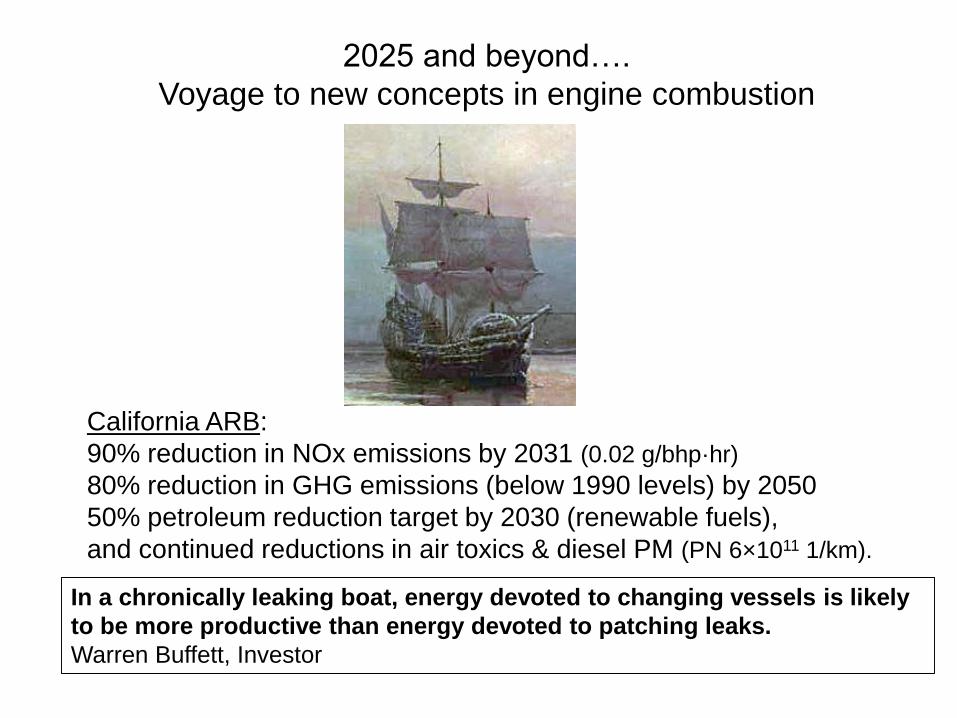
2025 and beyond….
Voyage to new concepts in engine combustion
California ARB:
90% reduction in NOx emissions by 2031 (0.02 g/bhp·hr)
80% reduction in GHG emissions (below 1990 levels) by 2050
50% petroleum reduction target by 2030 (renewable fuels),
and continued reductions in air toxics & diesel PM (PN 6×10¹¹ 1/km).
In a chronically leaking boat, energy devoted to changing vessels is likely
to be more productive than energy devoted to patching leaks.
Warren Buffett, Investor
43 Engine Research Center, 2016
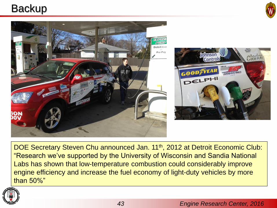
Backup
DOE Secretary Steven Chu announced Jan. 11th, 2012 at Detroit Economic Club:
“Research we’ve supported by the University of Wisconsin and Sandia National
Labs has shown that low-temperature combustion could considerably improve
engine efficiency and increase the fuel economy of light-duty vehicles by more
than 50%”