reactive power compensation in inverter interfaced...
TRANSCRIPT

Special Issue of International Journal of Power System Operation and Energy Management, ISSN (PRINT): 2231 – 4407, Volume - 1, Issue-3
12
Reactive Power Compensation in
Inverter Interfaced Distributed Generation
1Satyaranjan Jena & 2B.Chitti Babu 1Department of Electrical & Electronics Engineering, Hi-Tech Institute of Technology, Khurda, Odisha-752057, India
2Department of Electrical Engineering, National Institute of Technology, Rourkela, Odisha-769008, India E-mail : [email protected]
Abstract - The consumption of reactive power is stochastic in nature for the distribution system. This uncertain variation of the reactive power leads to 1) Variation of voltage at the point of common coupling(PCC) 2)Low power factor 3)low efficiency 4) improper utilization of distribution system and 5) loss of synchronism for a grid connected inverter based – distributed generation. Now a day’s distributed generation (DG) system uses current regulated PWM voltage-source inverters (VSI) for synchronizing the utility grid with DG source in order to ensure the grid stability. In this paper reactive power compensation based hysteresis controller and adaptive hysteresis controller is analyzed for inverter interfaced DG which can control the active and reactive power independently. The adaptive hysteresis controller can reduce the current harmonic at PCC considerably which ensures lower total harmonic distortion (THD). The performance indices include THD of the grid current, fast current tracking during steady state and transient conditions. The studied system is modeled and simulated in the MATLAB Simulink environment.
Index Terms-Adaptive hysteresis current control, distributed generation (DG), voltage source inverter (VSI), utility grid, total harmonic distortion (THD).
I. NOMENCLATURE
ILa,iLb,iLc : three phase grid current
ild,ilq : d and q axis current
ω : angular frequency
θ : transformation angle
Vd,Vq : d-q component of PCC voltage
Pref : reference value of active power
Vdc : dc-link voltage
Va,Vb,Vc : grid voltage per phase
fc : modulation frequency
L : line inductance
Vpcc : voltage at PCC
II. INTRODUCTION :
NDER the restructuring phase of the electric power industry, the traditional vertically integrated utility environment is inevitably being changed. The power system operation will become more competitive and many challenges will arise. Since it is a clean energy source, it has lower impact to the environment, and
never runs out, DG based on renewable and non renewable energy is a hot issue in today competitive market [1].
In conventional generation stations, the generators operate at a fixed speed and thereby with a fixed grid-frequency; however, the dispersed generation presents a quite different and challenging picture. For example, the voltage generated by variable speed wind power generators, PV generators and fuel cells cannot be directly connected to the grid. The power electronic technology plays a vital role to match the characteristics of the dispersed generation units and the requirements of the grid connections, including frequency, voltage, and control. Power electronics is an efficient essential part for the integration of DG unit to achieve high efficiency and performance in power systems [2].
One important part of the distributed system is its control. The control tasks can be divided into two major parts. 1) Input-side controller, with the main property to extract the maximum power from the input source. 2) Grid-side controller, which can have the task like, control of active power generated to the grid, control of reactive power transfer between the DPGS and the grid; control of dc-link voltage, ensure high quality of the injected power, grid synchronization [3]
Special Issue
The currepreferred for iquick responsecontroller forccommand in stechniques habecause they othe dynamics under field-orof current ccomparator, controller.[4]
The ramp-current signagenerate the inof the ramp cswitching’s utriangular wavdefined at a response is afffeedback loopThus, inherentthe steady calculate the currents to fogives optimumtime and accrequires a goohysteresis currare used to imreference curprovides excelquickly. Howvariation of th
In the distrunity power fapower componThis reactive power factor,ldistribution sy
The objectreactive powealong with inpower. The pethe implemenhysteresis curr
The paper strategies in gII. Single-phasection III. Ancontroller is dedicated to conclusion in s
Re
of International Jo
ent-controlled inter-facing DGe and accurate ces the load cusome power apave become anoffer substantia
in high-perfrientation contrcontrollers can
hysteresis c
-comparator col to a triangnverter firing pcomparison tecusually limitedveform, and th
fixed frequenffected by the sp, which also dt phase and amstate conditioinverter volt
ollow the currm performancecuracy, it takod knowledge rent controller
mpose a dead barrent. The hllent dynamic wever, the me switching fre
ribution systemfactor reactive nent of currentpower compo
low efficiency ystem [7].
tive of this arer during the
ndependent conerformances ontation of therent controller
is organized agrid connected ase grid connnalysis of hystexplained in
results and section VI. refe
active Power Co
ournal of Power Sy
PWM-VSI G to the utilitycontrol. Basic
urrent to follopparatus. Currn intensive resal advantages
formance ac drol. The commn be classifiontroller, an
ontroller compgular carrier pulses. The mchnique is thad to the frequhe produced hncy. Howeverstability requirdepends on loamplitude errors on. Predictiveage required ent referencese in terms of bkes more calcof the load pa, the hysteresiand or hysterehysteresis conperformance b
main disadvanequency. [5][6]
m the major lload which drt along with a
onent of currenand poor util
rticle is to covariation of
ntrol of activef the system ie hysteresis
as follows – csystem are giv
nected VSI is teresis and adthe section IV
discussion, ferences in sect
ompensation in I
ystem Operation an
is usually y grid as it has cally, a current ow the current rent controller search subject in eliminating drive systems mon strategies ied as ramp
nd predictive
pares the error waveform to
main advantage at the inverter uency of the harmonics are r, the system rements of the ad parameters.
arise, even in e controllers to force the
s. Although it both response culations and rameters. In a s comparators sis around the ntrol scheme because it acts ntage is the ].
loads are non raw a reactive active power.
nt causes low lization of the
ompensate the load demand
e and reactive s analyzed by and adaptive
urrent control ven in section
described in aptive current V. Section V followed by
tion VII.
Inverter Interface
nd Energy Manag13
III. CURGR
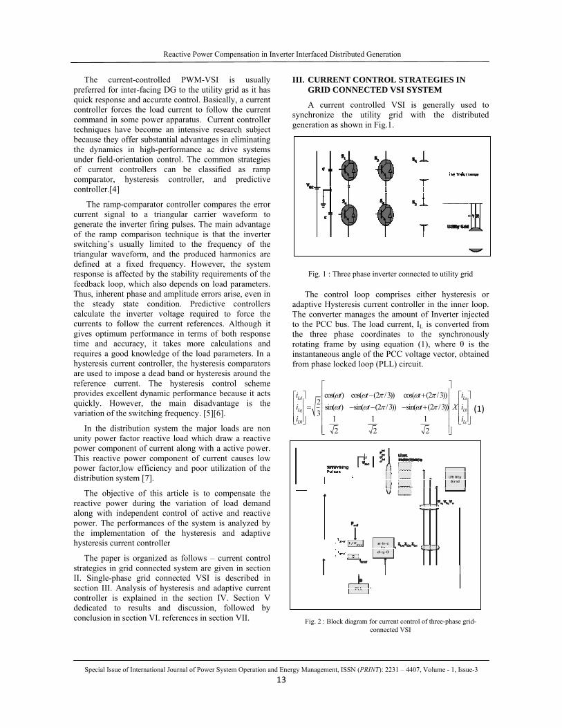
A csynchrongeneratio
Fig.
The adaptiveThe conto the Pthe threrotating instantanfrom pha
0
23
Ld
Lq
L
iii
⎡ ⎤⎢ ⎥=⎢ ⎥⎢ ⎥⎣ ⎦
Fig. 2
ed Distributed G
ement, ISSN (PRI
RRENT CONRID CONNEC
current contronize the utilon as shown in
1 : Three phase
control loop e Hysteresis cunverter manageCC bus. The lee phase cooframe by usi
neous angle ofase locked loop
cos( ) cos(sin( ) sin(
12
t tt tω ωω ω
⎡⎢ −⎢
−⎢⎢⎢⎢⎣
2 : Block diagram f
Generation
INT): 2231 – 4407
NTROL STRATED VSI SYS
olled VSI is lity grid witn Fig.1.
e inverter connec
comprises eurrent controllees the amount load current, Iordinates to ing equation (f the PCC voltap (PLL) circuit
(2 /3)) cos((2 /3)) sin(
12
tπ ωπ ω
−− −
for current controlconnected VSI
, Volume - 1, Issu
ATEGIES IN STEM
generally useth the distri
cted to utility gri
either hystereser in the inner of Inverter injL is convertedthe synchron
(1), where θ iage vector, obtt.
(2 /3))(2 /3))
12
La
Lb
Lc
t it X i
i
ω πω π
⎤⎥+ ⎡ ⎤⎥ ⎢ ⎥+ ⎥ ⎢ ⎥⎥ ⎢ ⎥⎣ ⎦⎥⎥⎦
l of three-phase gri
ue-3
ed to ibuted
d
sis or loop.
jected d from nously is the tained
⎤
⎦ (1)
id-

Special Issue
The adjusthe voltage at regulator contrtransformation
PLLP qk vω = +
( dtθ ω= ×∫ It is assusequence comcan be ignoreconsidered in case.
The resulreactive powecompensate tcomponent (i.IInverter, equal toload current (I
The generthe dP v i= ×
&d PCCv v=
Hence
dPCC
PIV
=
Selecting tcommand signbe rewritten, a
refd ref
PCC
PI
V=
Where idrefcurrent of thresponsible focapacitor. Finrotating at the
Re
of International Jo
Fig. 3 : Block
stment of the dthe PCC has
rols the angulan angle can be
(PLLI qk v+ ×∫
)t
umed that thermponents, there
ed. However, the formulat
ltant q-componer flow througthe reactive c.e., iqref) of theo the quadraturILoad) .
rated active po
d q qi v i+ ×
0qv =
he reference anal given of theas follows:
f is the direct e VSI, IInverter
or the losses innally, applyinge supply freque
active Power Co
ournal of Power Sy
diagram of PL
dq-transformatno q-axis com
ar frequency bydetermined by
)dt
re is no path fore i0 in (1) athese variable
tion to presen
nent is respongh the utility component the reference cure component (
ower of DG is
active power oe utility the eq
component of r. This compo
n both the convg inverse dq tency ω by the
ompensation in I
ystem Operation an
LL
tion is so that mponent. A PI y (2). Then the y (3).
(2)
(3)
for the zero and v0 in Fig.3 es have been
nt the general
nsible for the network. To
he quadrature urrent of VSI, (i.e., ilq) of the
expressed by (4)
(5)
(6)
of DG as the quation (6) can
(7)
f the reference onent is also verter and the transformation e equation (8),
Inverter Interface
nd Energy Manag14
the threefrom the
aref
bref
cref
iii
⎡ ⎤ ⎡⎢ ⎥ ⎢=⎢ ⎥ ⎢⎢ ⎥ ⎢⎣⎣ ⎦
IV. ANAADACO
Theproven tcurrent hysteresunconditaccuracytechniqusuch as unoise anconventiused forcomposecurrent current o, measurreferred referred assigns t
δ =
The swit
If δ >HB
(S4=1
If δ <-HB
(S4=0
Theusing coand hyst
In cchange othereforeconstantalong winductandc link vrate of c
On tcurrent accordin
ed Distributed G
ement, ISSN (PRI
e-phase VSI re d-q reference
sin( )sin( (2 / 3)sin( (2 / 3)
ttt
ωω πω π
⎡−+⎣
ALYSIS OF HAPTIVE HYSNTROLLER
e hysteresis bato be most su
controlled vis band curretioned stabilityy. On the otue exhibits aluneven switchnd difficulty ional hysteresr the control oed of a hyste[9]. By noticeof the grid conred line curren
to as i and to as δ. The h
the switching p
refi i= −
tching logic is
B upper switch
1, S1=0).
B upper switch
0, S1=1).
e switching logorresponding rteresis bandwid
case of hysteresof the line curre the switchit throughout th
with the currentnce value of thvoltage are thehange of grid c
the other hancontroller ch
ng to instantan
Generation
INT): 2231 – 4407
reference currecomponents [8
cos( ))) cos( (2)) cos( (2
ttt
ωω πω π
−+
HYSTERESISSTERESIS CU
and current couitable for all voltage sourcent control isy, very fast rther hand, thlso several uning frequency in designing
sis band curreof grid conneeresis around e equation (9)
nnected inverternt of the grid c
difference behysteresis banpattern of grid
(
formulated as
is OFF and low
h is ON and low
gic for phases Breference and dth (HB).
sis band currenrent vary the sing frequencyhe switching ot waveform. Fuhe grid connece main parametconnected inve
d The adaptihanges the hyneous current v
, Volume - 1, Issu
ents are determ8].
1/ 3)) 1/ 3)) 1
La
Lb
Lc
iX i
iππ
⎤ ⎡ ⎤⎥ ⎢ ⎥⎥ ⎢ ⎥⎥ ⎢ ⎥⎦ ⎣ ⎦
S AND URRENT
ontrol techniquthe applicatio
ce inverters. s characterizeresponse, and he basic hystndesirable feathat causes acoinput filters.
ent control sccted line currethe reference
) the referencer is referred to onnected inver
etween i and nd current contconnected inve
(9)
follows:
wer switch is O
wer switch is O
B and C is simimeasured cu
nt control the rwitching frequ
y does not reoperation, but vurthermore, thted inverter anters determininerter line curren
ve hysteresis ysteresis bandvariation ( diar
ue-3
mined
⎤
⎦
(8)
ue has ons of
The ed by
good teresis atures; oustic . The cheme ent is e line e line as iref
rter is iref is troller erter.
ON
OFF
ilarly, urrents
rate of uency, emain varies
he line nd the ng the nts.
band dwidth ref/dt )
Special Issue
and Vdc voltadistortion on m
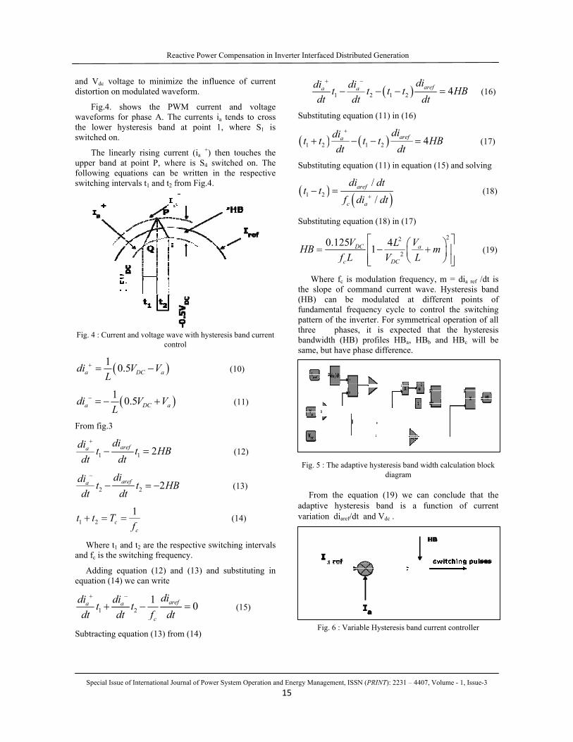
Fig.4. shwaveforms fothe lower hyswitched on.
The lineaupper band atfollowing equswitching inter
Fig. 4 : Current
(1 0.adiL
+ =
(1 0adiL
− = −
From fig.3
1ara didi t
dt dt
+
−
2ara didi t
dt dt
−
−
1 2 ct t T+ = =
Where t1 anand fc is the sw
Adding equequation (14) w
1a adi dit
dt dt
+ −
+
Subtracting eq
Re
of International Jo
age to minimizmodulated wav
hows the PWr phase A. Th
ysteresis band
arly rising currt point P, wheuations can bervals t1 and t2 f
t and voltage wavcon
)5 DC aV V−
)0.5 DC aV V+
1 2ref t HBt
=
2 2ref t HBt
= −
1
cf=
nd t2 are the rewitching freque
uation (12) anwe can write
21 are
c
dit
f dt
−
−
quation (13) fro
active Power Co
ournal of Power Sy
ze the influenveform.
WM current he currents ia t
at point 1,
rent (ia +) thenere is S4 swite written in tfrom Fig.4.
ve with hysterestrol
B
espective switcency.
nd (13) and s
0ef =
om (14)
ompensation in I
ystem Operation an
nce of current
and voltage tends to cross where S1 is
n touches the tched on. The the respective
sis band current
(10)
(11)
(12)
(13)
(14)
ching intervals
substituting in
(15)
Inverter Interface
nd Energy Manag15
adidt
+
Substitu
( )1 2t t+
Substitu
( )1 2t t−
Substitu
0HB =
Whethe slop(HB) cfundamepattern othree bandwidsame, bu
Fig. 5 : T
Fromadaptivevariation
Fig
ed Distributed G
ement, ISSN (PRI
1 2adit t
dt
+ −
− −
uting equation (
) ( 1adi t
dt
+
− −
uting equation (
) (//
aref
c a
di df di +
=
uting equation (
0.125 1DC
c
Vf L
⎡−⎢
⎢⎣
ere fc is modulpe of commancan be modental frequencyof the inverter. phases, it
dth (HB) profut have phase d
The adaptive hy
m the equatione hysteresis bn diaref/dt and
g. 6 : Variable Hy
Generation
INT): 2231 – 4407
( )1 2ardi
t tdt
− −
(11) in (16)
)2 4arefdit
dt=
(11) in equation
)/dtdt
(18) in (17)
2
2
4 a
DC
VLV L
⎛− +⎜⎝
lation frequencnd current wavdulated at diy cycle to co. For symmetris expected t
files HBa, HBdifference.
ysteresis band widiagram
n (19) we canband is a fuVdc .
ysteresis band cu
, Volume - 1, Issu
4ref HBt
=
4HB
n (15) and solv
2
m⎤⎞+ ⎥⎟
⎠ ⎥⎦
cy, m = dia refve. Hysteresis ifferent point
ontrol the switrical operation that the hystb and HBc w
idth calculation b
n conclude thaunction of cu
urrent controller
ue-3
(16)
(17)
ving
(18)
(19)
/dt is band
ts of tching of all
teresis will be
block
at the urrent
r
Reactive Power Compensation in Inverter Interfaced Distributed Generation
Special Issue of International Journal of Power System Operation and Energy Management, ISSN (PRINT): 2231 – 4407, Volume - 1, Issue-3
16
V. RESULTS & DISCUSSION
The section reveals the simulation results for hysteresis and adaptive hysteresis current control algorithm applied to three-phase mains connected inverter system. The studied model has been developed and simulated in the MATLAB/simulink environment. For simulation, the Dc-link voltage is taken 600V, and the grid voltage is 400V (L-L). the modulation frequency is taken 10KHz and the command value of power is set to 3.5Kw.
A. Steady State Analysis
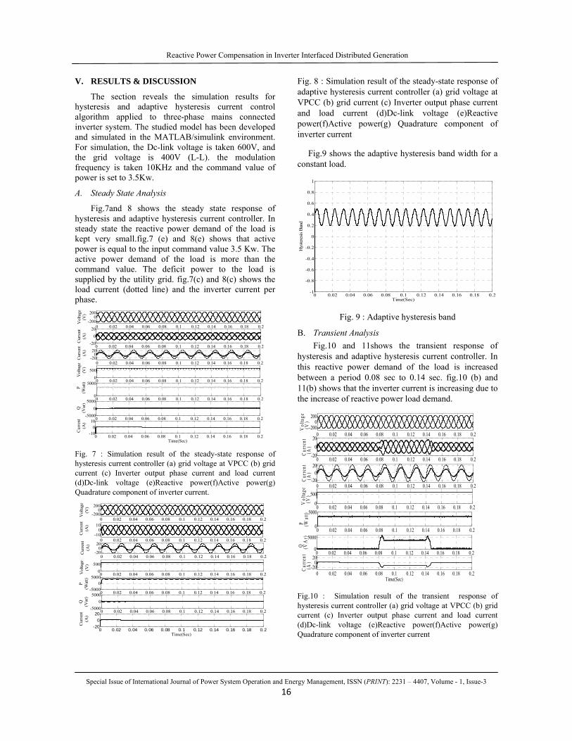
Fig.7and 8 shows the steady state response of hysteresis and adaptive hysteresis current controller. In steady state the reactive power demand of the load is kept very small.fig.7 (e) and 8(e) shows that active power is equal to the input command value 3.5 Kw. The active power demand of the load is more than the command value. The deficit power to the load is supplied by the utility grid. fig.7(c) and 8(c) shows the load current (dotted line) and the inverter current per phase.
Fig. 7 : Simulation result of the steady-state response of hysteresis current controller (a) grid voltage at VPCC (b) grid current (c) Inverter output phase current and load current (d)Dc-link voltage (e)Reactive power(f)Active power(g) Quadrature component of inverter current.
Fig. 8 : Simulation result of the steady-state response of adaptive hysteresis current controller (a) grid voltage at VPCC (b) grid current (c) Inverter output phase current and load current (d)Dc-link voltage (e)Reactive power(f)Active power(g) Quadrature component of inverter current
Fig.9 shows the adaptive hysteresis band width for a constant load.
Fig. 9 : Adaptive hysteresis band
B. Transient Analysis Fig.10 and 11shows the transient response of
hysteresis and adaptive hysteresis current controller. In this reactive power demand of the load is increased between a period 0.08 sec to 0.14 sec. fig.10 (b) and 11(b) shows that the inverter current is increasing due to the increase of reactive power load demand.
Fig.10 : Simulation result of the transient response of hysteresis current controller (a) grid voltage at VPCC (b) grid current (c) Inverter output phase current and load current (d)Dc-link voltage (e)Reactive power(f)Active power(g) Quadrature component of inverter current
0 0.02 0.04 0.06 0.08 0.1 0.12 0.14 0.16 0.18 0.2-200
0200
Vol
tage
(V)
0 0.02 0.04 0.06 0.08 0.1 0.12 0.14 0.16 0.18 0.2-20
020
Cur
rent
(A)
0 0.02 0.04 0.06 0.08 0.1 0.12 0.14 0.16 0.18 0.2-20
020
Cur
rent
(A)
0 0.02 0.04 0.06 0.08 0.1 0.12 0.14 0.16 0.18 0.20
500
Vol
tage
(V)
0 0.02 0.04 0.06 0.08 0.1 0.12 0.14 0.16 0.18 0.20
5000
P(W
att)
0 0.02 0.04 0.06 0.08 0.1 0.12 0.14 0.16 0.18 0.2-5000
05000
Q(V
ar)
0 0.02 0.04 0.06 0.08 0.1 0.12 0.14 0.16 0.18 0.2-10
010
Time(Sec)
Cur
rent
(A)
0 0.02 0.04 0.06 0.08 0.1 0.12 0.14 0.16 0.18 0.2-200
0200
Vol
tage
(V)
0 0.02 0.04 0.06 0.08 0.1 0.12 0.14 0.16 0.18 0.2-10
010
Cur
rent
(A)
0 0.02 0.04 0.06 0.08 0.1 0.12 0.14 0.16 0.18 0.2-20
020
Cur
rent
(A)
0 0.02 0.04 0.06 0.08 0.1 0.12 0.14 0.16 0.18 0.20
500
Vol
tage
(V)
0 0.02 0.04 0.06 0.08 0.1 0.12 0.14 0.16 0.18 0.2-5000
05000
P(W
att)
0 0.02 0.04 0.06 0.08 0.1 0.12 0.14 0.16 0.18 0.2-5000
05000
Q(V
ar)
0 0.02 0.04 0.06 0.08 0.1 0.12 0.14 0.16 0.18 0.2-20
020
Time(Sec)
Cur
rent
(A)
0 0.02 0.04 0.06 0.08 0.1 0.12 0.14 0.16 0.18 0.2-1
-0.8
-0.6
-0.4
-0.2
0
0.2
0.4
0.6
0.8
1
Time(Sec)H
yste
resi
s B
and
0 0.02 0.04 0.06 0.08 0.1 0.12 0.14 0.16 0.18 0.2-200
0200
Vol
tage
(V)
0 0.02 0.04 0.06 0.08 0.1 0.12 0.14 0.16 0.18 0.2-20
020
Cur
rent
(A)
0 0.02 0.04 0.06 0.08 0.1 0.12 0.14 0.16 0.18 0.2-20
020
Cur
rent
(A)
0 0.02 0.04 0.06 0.08 0.1 0.12 0.14 0.16 0.18 0.20
500
Vol
tage
(V)
0 0.02 0.04 0.06 0.08 0.1 0.12 0.14 0.16 0.18 0.20
5000
P
(W
att)
0 0.02 0.04 0.06 0.08 0.1 0.12 0.14 0.16 0.18 0.20
5000
Q
(V
Ar)
0 0.02 0.04 0.06 0.08 0.1 0.12 0.14 0.16 0.18 0.2-20
020
Time(Sec)
Cur
rent
(A)

Reactive Power Compensation in Inverter Interfaced Distributed Generation
Special Issue of International Journal of Power System Operation and Energy Management, ISSN (PRINT): 2231 – 4407, Volume - 1, Issue-3
17
In described control scheme the PWM-VSI is able to inject the reactive power when the load demand increases which can be analyze by observing Fig10 (f) and 11(f).As far as the active power is concerned Fig 10(e) and 11(e) shows that the active power is almost constant and equal to the input command value (3.5Kw). Fig. 10(g) and 11(g) shows the quadrature component of the inverter current under dynamic change in the load reactive power.
Fig. 11 : Simulation result of the transient response of adaptive hysteresis current controller (a) grid voltage at VPCC (b) grid current (c) Inverter output phase current and load current (d)Dc-link voltage (e)Reactive power(f)Active power(g) Quadrature component of inverter current
Fig. 12 : Adaptive hysteresis band
As the hysteresis band is function of diaref/dt and VDC hence the band width changes according to the variation of load. by changing the band width the user can control the average switching frequency of the grid connected inverter.
Fig. 13 : Response of reference current, actual current and
current error for hysteresis current controller
The dynamic response of the hysteresis current controller is better than adaptive hysteresis controller but the current error is more in case of hysteresis current controller as shown in fig. 13 as compared to adaptive hysteresis current controller shown in Fig .14.
Fig. 14 : Response of reference current, actual current and
current error for adaptive hysteresis current controller.
Fig. 15 : THD of grid current for hysteresis current controller
0 0.02 0.04 0.06 0.08 0.1 0.12 0.14 0.16 0.18 0.2-200
0200
Vol
tage
(V)
0 0.02 0.04 0.06 0.08 0.1 0.12 0.14 0.16 0.18 0.2-20
020
Cur
rent
(A)
0 0.02 0.04 0.06 0.08 0.1 0.12 0.14 0.16 0.18 0.2-20
020
Cur
rent
(A)
0 0.02 0.04 0.06 0.08 0.1 0.12 0.14 0.16 0.18 0.20
500
Vol
tage
(V)
0 0.02 0.04 0.06 0.08 0.1 0.12 0.14 0.16 0.18 0.20
5000
P
(W
att)
0 0.02 0.04 0.06 0.08 0.1 0.12 0.14 0.16 0.18 0.20
5000
Q
(V
ar)
0 0.02 0.04 0.06 0.08 0.1 0.12 0.14 0.16 0.18 0.2-20
020
Time(Sec)
Cur
rent
(A)
0 0.02 0.04 0.06 0.08 0.1 0.12 0.14 0.16 0.18 0.2-1
-0.8
-0.6
-0.4
-0.2
0
0.2
0.4
0.6
0.8
1
Time(Sec)
Hys
teresis Ban
d
0.06 0.065 0.07 0.075 0.08 0.085 0.09 0.095 0.1-30
-20
-10
0
10
20
30
Time(Sec)
Cur
rent
(A)
Actual CurrentReference CurrentError
0.06 0.065 0.07 0.075 0.08 0.085 0.09 0.095 0.1-30
-20
-10
0
10
20
30
Time(Sec)
Cur
ent(A
)
Refernce currentErrorActual Current
0 500 1000 1500 2000 25000
2
4
6
8
10
Frequency (Hz)
Fundamental (50Hz) = 10.08 , THD= 2.69%
Mag
Reactive Power Compensation in Inverter Interfaced Distributed Generation
Special Issue of International Journal of Power System Operation and Energy Management, ISSN (PRINT): 2231 – 4407, Volume - 1, Issue-3
18
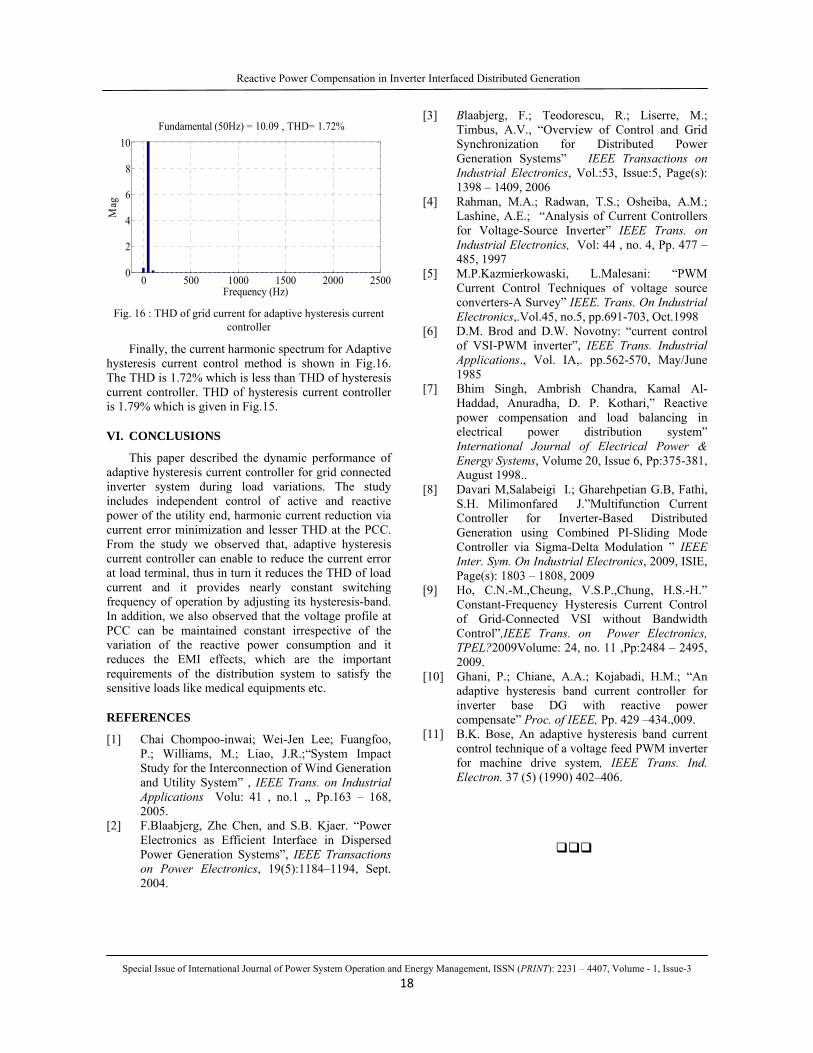
Fig. 16 : THD of grid current for adaptive hysteresis current
controller
Finally, the current harmonic spectrum for Adaptive hysteresis current control method is shown in Fig.16. The THD is 1.72% which is less than THD of hysteresis current controller. THD of hysteresis current controller is 1.79% which is given in Fig.15.
VI. CONCLUSIONS
This paper described the dynamic performance of adaptive hysteresis current controller for grid connected inverter system during load variations. The study includes independent control of active and reactive power of the utility end, harmonic current reduction via current error minimization and lesser THD at the PCC. From the study we observed that, adaptive hysteresis current controller can enable to reduce the current error at load terminal, thus in turn it reduces the THD of load current and it provides nearly constant switching frequency of operation by adjusting its hysteresis-band. In addition, we also observed that the voltage profile at PCC can be maintained constant irrespective of the variation of the reactive power consumption and it reduces the EMI effects, which are the important requirements of the distribution system to satisfy the sensitive loads like medical equipments etc.
REFERENCES
[1] Chai Chompoo-inwai; Wei-Jen Lee; Fuangfoo, P.; Williams, M.; Liao, J.R.;“System Impact Study for the Interconnection of Wind Generation and Utility System” , IEEE Trans. on Industrial Applications Volu: 41 , no.1 ,, Pp.163 – 168, 2005.
[2] F.Blaabjerg, Zhe Chen, and S.B. Kjaer. “Power Electronics as Efficient Interface in Dispersed Power Generation Systems”, IEEE Transactions on Power Electronics, 19(5):1184–1194, Sept. 2004.
[3] Blaabjerg, F.; Teodorescu, R.; Liserre, M.; Timbus, A.V., “Overview of Control and Grid Synchronization for Distributed Power Generation Systems” IEEE Transactions on Industrial Electronics, Vol.:53, Issue:5, Page(s): 1398 – 1409, 2006
[4] Rahman, M.A.; Radwan, T.S.; Osheiba, A.M.; Lashine, A.E.; “Analysis of Current Controllers for Voltage-Source Inverter” IEEE Trans. on Industrial Electronics, Vol: 44 , no. 4, Pp. 477 – 485, 1997
[5] M.P.Kazmierkowaski, L.Malesani: “PWM Current Control Techniques of voltage source converters-A Survey” IEEE. Trans. On Industrial Electronics,.Vol.45, no.5, pp.691-703, Oct.1998
[6] D.M. Brod and D.W. Novotny: “current control of VSI-PWM inverter”, IEEE Trans. Industrial Applications., Vol. IA,. pp.562-570, May/June 1985
[7] Bhim Singh, Ambrish Chandra, Kamal Al-Haddad, Anuradha, D. P. Kothari,” Reactive power compensation and load balancing in electrical power distribution system” International Journal of Electrical Power & Energy Systems, Volume 20, Issue 6, Pp:375-381, August 1998..
[8] Davari M,Salabeigi I.; Gharehpetian G.B, Fathi, S.H. Milimonfared J.”Multifunction Current Controller for Inverter-Based Distributed Generation using Combined PI-Sliding Mode Controller via Sigma-Delta Modulation ” IEEE Inter. Sym. On Industrial Electronics, 2009, ISIE, Page(s): 1803 – 1808, 2009
[9] Ho, C.N.-M.,Cheung, V.S.P.,Chung, H.S.-H.” Constant-Frequency Hysteresis Current Control of Grid-Connected VSI without Bandwidth Control”,IEEE Trans. on Power Electronics, TPEL?2009Volume: 24, no. 11 ,Pp:2484 – 2495, 2009.
[10] Ghani, P.; Chiane, A.A.; Kojabadi, H.M.; “An adaptive hysteresis band current controller for inverter base DG with reactive power compensate” Proc. of IEEE, Pp. 429 –434.,009.
[11] B.K. Bose, An adaptive hysteresis band current control technique of a voltage feed PWM inverter for machine drive system, IEEE Trans. Ind. Electron. 37 (5) (1990) 402–406.
0 500 1000 1500 2000 25000
2
4
6
8
10
Frequency (Hz)
Fundamental (50Hz) = 10.09 , THD= 1.72%M
ag