re type gms, gmss, gmsw, 14 060/03.96 …...re 14 060/03.96 2/26 hydraulik nord symbols type gms,...
TRANSCRIPT

RE14 060/03.96
1/26Hydraulik Nord
RE14 060/03.96
Gerotormotors (Low Speed High Torque Motors)Type GMS, GMSS, GMSW,
GMT, GMTS, GMTW
Standard motor type GMS Standard motor type GMT
Short motor type GMTS Wheel motor type GMTW
Characteristics:– Very smooth running, even at low speeds– Wide speed range– Constant output torque over a wide speed range– High starting torque– Robust design capable of withstanding tough operating
conditions– Favorable power-to-weight ratio– Operation without a leakage oil line, even when exposed
to high backflow pressures– Can be connected in series
Applications:– Agricultural and forestry vehicles– Conveyor systems– Cranes and transport systems– Municipal vehicles (road sweepers, snow clearers, road
gritters, etc.)– Construction machinery– Mining equipment– Winch drives– Plastics machinery– Wood processing machinery– Machine tools– Shipbuilding
ContentsName pageCharacteristics, applications 1Motor type: GMS, GMSS and GMSW
Mode of operation, variants, section, symbol 2Ordering code and weights 3,4Technical data 5Operating curve 6-9Direction of shaft rotation 9Permissible shaft load, Shaft version 10Unit dimensions GMS 11Unit dimensions GMSW 12Unit dimensions GMSS 13GMSS-assembly, leakage oil and add-on components 14
Motor type: GMT, GMTS and GMTWOrdering code and weights 14,15Technical data 17Operating curve 18-20Direction of shaft rotation 20Permissible shaft load 21Shaft version 22Unit dimensions GMT 23Unit dimensions GMTW 24Unit dimensions GMTS 25GMTS-assembly, leakage oil and add-on components 26
Hydraulik Nord

RE 14 060/03.96
2/26 Hydraulik Nord
Symbols Type GMS, GMT
Functional Description, Section
Gerotor motors are robust hydraulic driveline elements withuniversal applications.
The Gerotor has a special design feature (Gerotor reduction)that allows low output speeds without the need for additionalgear stages. In many cases, this can help to reduce costsand cut down weight.
Gerotor motors are self-lubricating and practicallymaintenance-free, merely requiring a regular oil change.
The Gerotor motors cover a torque spectrum from 10 daNmto 100 daNm and operate in a power range from 10 kW to30 kW.
Mode of operation:Gerotor motors are internally geared motors that converthydraulic energy into mechanical energy.
The Gerotor consists of a ring with an internal gear profile,and an excentric pinion mounted in this internal ring gear. Thepinion has one tooth less than the internal ring gear and soonly advances by one tooth space every time it rotates withinthe ring. This results in the speed reduction which ensures
good low-speed characteristics and high output torques.
A cardan shaft with crowned profile on either end transmitsthe power from the pinion to the output shaft.
Series GMS and GMT motors are controlled using a rotatingdisc valve driven by a second, shorter cardan shaft.
Motor torque is dependent on the size of motor (cc perrevolution) and the pressure differential between the inlet andoutlet connections.
Variants
The motors offers a wide choice of special versions for particularapplications in addition to its comprehensive range of standardmotors.
– Wheel motors with recessed mounting flange
– Short motors for use with gearboxes
1 Prop shaft2 Gerotor3 Steering shaft4 Disc valve5 Output shaft6 Taperd bearing7 Check valve
1 2 3 4
5 6 7
RE14 060/03.96
3/26Hydraulik Nord
Further detailsin clear text
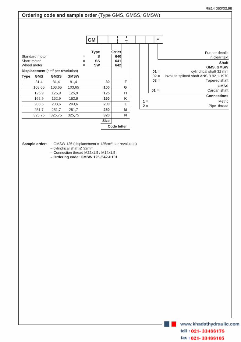
ShaftGMS, GMSW
01 = cylindrical shaft 32 mm02 = Involute splined shaft ANS B 92.1-197003 = Tapered shaft
GMSS01 = Cardan shaft
Connections
1 = Metric2 = Pipe thread
Sample order: – GMSW 125 (displacement = 125cm3 per revolution)– cylindrical shaft Ø 32mm– Connection thread M22x1,5 / M14x1,5– Ordering code: GMSW 125 /642-H101
Ordering code and sample order (Type GMS, GMSS, GMSW)
Type SeriesStandard motor = S 640Short motor = SS 641Wheel motor = SW 642
Displacement (cm3 per revolution)
Type GMS GMSS GMSW
81,4 81,4 81,4 80 F
103,65 103,65 103,65 100 G
125,9 125,9 125,9 125 H
162,9 162,9 162,9 160 K
203,6 203,6 203,6 200 L
251,7 251,7 251,7 250 M
325,75 325,75 325,75 320 N
Size
Code letter
GM / – *
RE 14 060/03.96
4/26 Hydraulik Nord
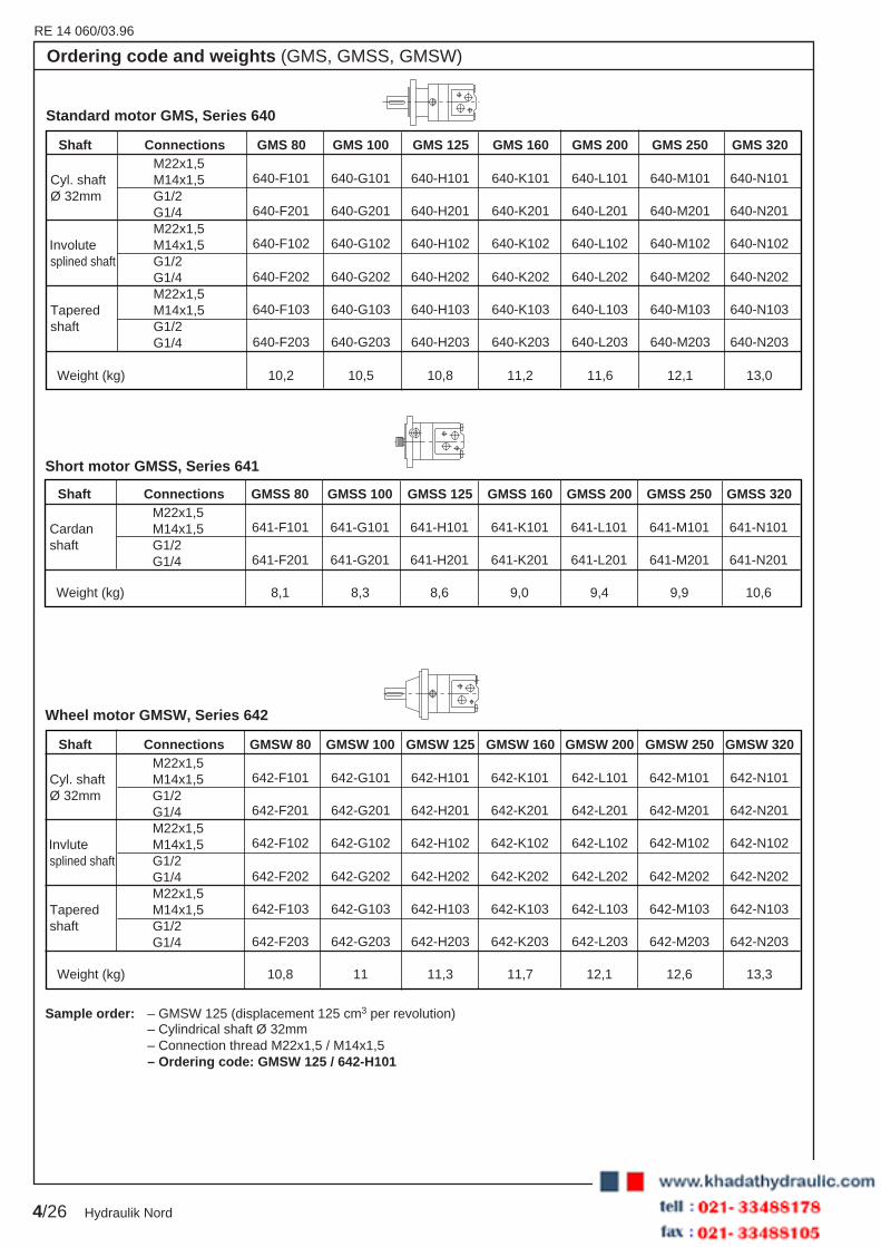
Shaft Connections GMS 80 GMS 100 GMS 125 GMS 160 GMS 200 GMS 250 GMS 320
640-F101 640-G101 640-H101 640-K101 640-L101 640-M101 640-N101
640-F201 640-G201 640-H201 640-K201 640-L201 640-M201 640-N201
640-F102 640-G102 640-H102 640-K102 640-L102 640-M102 640-N102
640-F202 640-G202 640-H202 640-K202 640-L202 640-M202 640-N202
640-F103 640-G103 640-H103 640-K103 640-L103 640-M103 640-N103
640-F203 640-G203 640-H203 640-K203 640-L203 640-M203 640-N203
Weight (kg) 10,2 10,5 10,8 11,2 11,6 12,1 13,0
M22x1,5Cyl. shaft M14x1,5Ø 32mm G1/2
G1/4M22x1,5
Involute M14x1,5splined shaft G1/2
G1/4M22x1,5
Tapered M14x1,5shaft G1/2
G1/4
Standard motor GMS, Series 640
Ordering code and weights (GMS, GMSS, GMSW)
Shaft Connections GMSS 80 GMSS 100 GMSS 125 GMSS 160 GMSS 200 GMSS 250 GMSS 320
641-F101 641-G101 641-H101 641-K101 641-L101 641-M101 641-N101
641-F201 641-G201 641-H201 641-K201 641-L201 641-M201 641-N201
Weight (kg) 8,1 8,3 8,6 9,0 9,4 9,9 10,6
M22x1,5Cardan M14x1,5shaft G1/2
G1/4
Short motor GMSS, Series 641
Shaft Connections GMSW 80 GMSW 100 GMSW 125 GMSW 160 GMSW 200 GMSW 250 GMSW 320
642-F101 642-G101 642-H101 642-K101 642-L101 642-M101 642-N101
642-F201 642-G201 642-H201 642-K201 642-L201 642-M201 642-N201
642-F102 642-G102 642-H102 642-K102 642-L102 642-M102 642-N102
642-F202 642-G202 642-H202 642-K202 642-L202 642-M202 642-N202
642-F103 642-G103 642-H103 642-K103 642-L103 642-M103 642-N103
642-F203 642-G203 642-H203 642-K203 642-L203 642-M203 642-N203
Weight (kg) 10,8 11 11,3 11,7 12,1 12,6 13,3
M22x1,5Cyl. shaft M14x1,5Ø 32mm G1/2
G1/4M22x1,5
Invlute M14x1,5splined shaft G1/2
G1/4M22x1,5
Tapered M14x1,5shaft G1/2
G1/4
Wheel motor GMSW, Series 642
Sample order: – GMSW 125 (displacement 125 cm3 per revolution)– Cylindrical shaft Ø 32mm– Connection thread M22x1,5 / M14x1,5– Ordering code: GMSW 125 / 642-H101

RE14 060/03.96
5/26Hydraulik Nord
Motor size 80 100 125 160 200 250 320
Geometric displacement cm3 81,4 103,65 125,9 162,9 203,6 251,7 325,75
Max. speed min-1 continuous 810 750 600 470 375 300 240
intermittent 1) 1000 900 720 560 450 360 285
Max. torque daNm continuous 20 25 32 34 40 45 54
intermittent 1) 24 30 38 48 50 54 63
Max. power output kW continuous 16 17,5 17,5 15,5 14 12,5 11,5
intermittent 1) 19 21 21 21 17,5 15 13,5
Max. pressure drop bar continuous 175 175 175 150 140 125 120
intermittent 1) 210 210 210 210 175 155 140
Max. oil flow L/min continuous 65 75 75 75 75 75 75
intermittent 1) 80 90 90 90 90 90 90
Max. input pressure bar continuous 210
intermittent 1) 250
Max. return pressure without drain line or max.pressure in drain line 2)
(0-100 min-1) bar continuous 75
(100-300 min-1) bar continuous 50
(300-810 min-1) bar continuous 20
(0-970 min-1) bar intermittent 1) 75
Max. return pressure with drain linebar continuous 140
intermittent 1) 175
Max. start pressure with unloaded shaftbar 12 10 10 8 8 8 8
Min. start torque at max. pressure dropdaNm continuous 15 19 25 27 31 33 41
Min. speed 3) min-1 10 10 10 10 10 10 10
1) Intermittent operation: operation max. 10 % per minute2) The pressure on the shaft seal is never greater than the
backflow pressure because of the built-in non-returnvalves. In the GMSS, this pressure is determined basedon the technical data of the add-on components.
3) You must expect that the motor will run less smoothly atspeeds below those specified here.
Technical Data : GMS, GMSS, GMSW (For applications outside these parameters, please consult us !)

RE 14 060/03.96
6/26 Hydraulik Nord
Operating Curves (measured at ν = 35mm2/s and t = 50 °C)
This performance data apply with a backflow pressure of5 - 10 bar, using a mineral oil-based hydraulic oil with aviscosity of 35 mm2/s at 50°C.
A: Endurance operation
B: Intermittent operation (operation max. 10 % per minute)
Note:Intermittent pressure drop must not coincide with fluctuationsin the oil flow.
Type GMS 80, GMSS 80, GMSW 80
Type GMS 100, GMSS 100, GMSW 100
1000 200 300 400 500 600 700 800 900 1000
5
10
15
20
25210
10 20 30 40 505 65 80
175
140
105
70
35
0
M(da Nm) qv (L/min)
∆p (bar)
n (min –1)
P (kW) η t (%)
18 kW
15 kW
12 kW
9 kW
3 kW
6 kW
85 %
80 %
70 %
A B
A
B
0 900
5
10 20 30 40 505 75 90
35
0
M(da Nm) qv (L/min)
∆p(bar)
n (min –1)
P (kW) η t (%)
A B
A
B
800700600500400300200100
70
105
140
175
210
10
15
20
25
30
60
85 %80 %
70 %
3 kW
6 kW9 kW
12 kW
15 kW 18 kW

RE14 060/03.96
7/26Hydraulik Nord
Type GMS 160, GMSS 160, GMSW 160
Type GMS 125, GMSS 125, GMSW 125
Operating Curves (measured at ν = 35mm2/s and t = 50 °C)
This performance data apply with a backflow pressure of5 - 10 bar, using a mineral oil-based hydraulic oil with aviscosity of 35 mm2/s at 50°C.
A: Endurance operation
B: Intermittent operation (operation max. 10 % per minute)
Note:Intermittent pressure drop must not coincide with fluctuationsin the oil flow.
0 750
5
10 20 30 40 505 75 90
30
0
M(da Nm) qv (L/min)
∆p (bar)
n (min –1)
P (kW) η t (%)
A B
B
700
60
90
120
175
21040
60
10
15
20
25
30
35
65060055050045040035030025020015010050
150A
3 kW
6 kW
9 kW
12 kW 15 kW
18 kW
85 %
80 % 70 %
0 600
5
10 20 30 40 505 75 90
30
0
M(da Nm) qv (l/min)
∆p (bar)
n (min –1)
P (kW) η t (%)
A B
60
90
120
175
210
55
60
50
150
A
10
15
20
25
30
35
40
45
50
100 150 200 250 300 350 400 450 500 550
B
85 %
80 %
70 %
3 kW
6 kW
9 kW
12 kW
15 kW
18 kW
RE 14 060/03.96
8/26 Hydraulik Nord
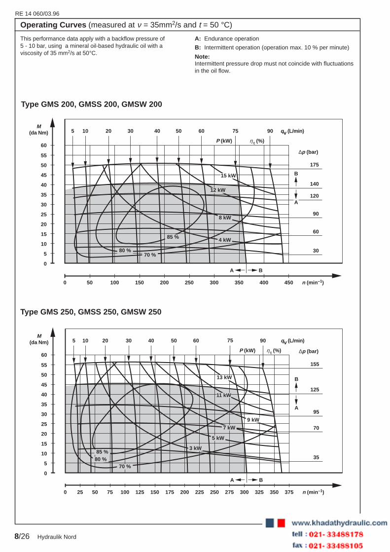
Type GMS 250, GMSS 250, GMSW 250
Type GMS 200, GMSS 200, GMSW 200
Operating Curves (measured at ν = 35mm2/s and t = 50 °C)
This performance data apply with a backflow pressure of5 - 10 bar, using a mineral oil-based hydraulic oil with aviscosity of 35 mm2/s at 50°C.
A: Endurance operation
B: Intermittent operation (operation max. 10 % per minute)
Note:Intermittent pressure drop must not coincide with fluctuationsin the oil flow.
0 450
5
10 20 30 40 505 75 90
30
0
M(da Nm) qv (L/min)
∆p (bar)
n (min –1)
P (kW) η t (%)
A B
60
90
120
175
60
60
50
140
A
B
10
15
20
25
30
35
40
45
50
55
100 150 200 250 300 350 400
70 %80 %
85 % 4 kW
8 kW
12 kW
15 kW
0 375
5
10 20 30 40 505 75 90
35
0
M(da Nm) qv (L/min)
∆p (bar)
n (min –1)
P (kW) η t (%)
A B
70
95
155
60
60
25
125
A
B
10
15
20
25
30
35
40
45
50
55
50 75 100 125 150 175 200 225 250 275 300 325 350
80 %85 %
70 %
3 kW
5 kW
7 kW
9 kW
11 kW
13 kW
RE14 060/03.96
9/26Hydraulik Nord
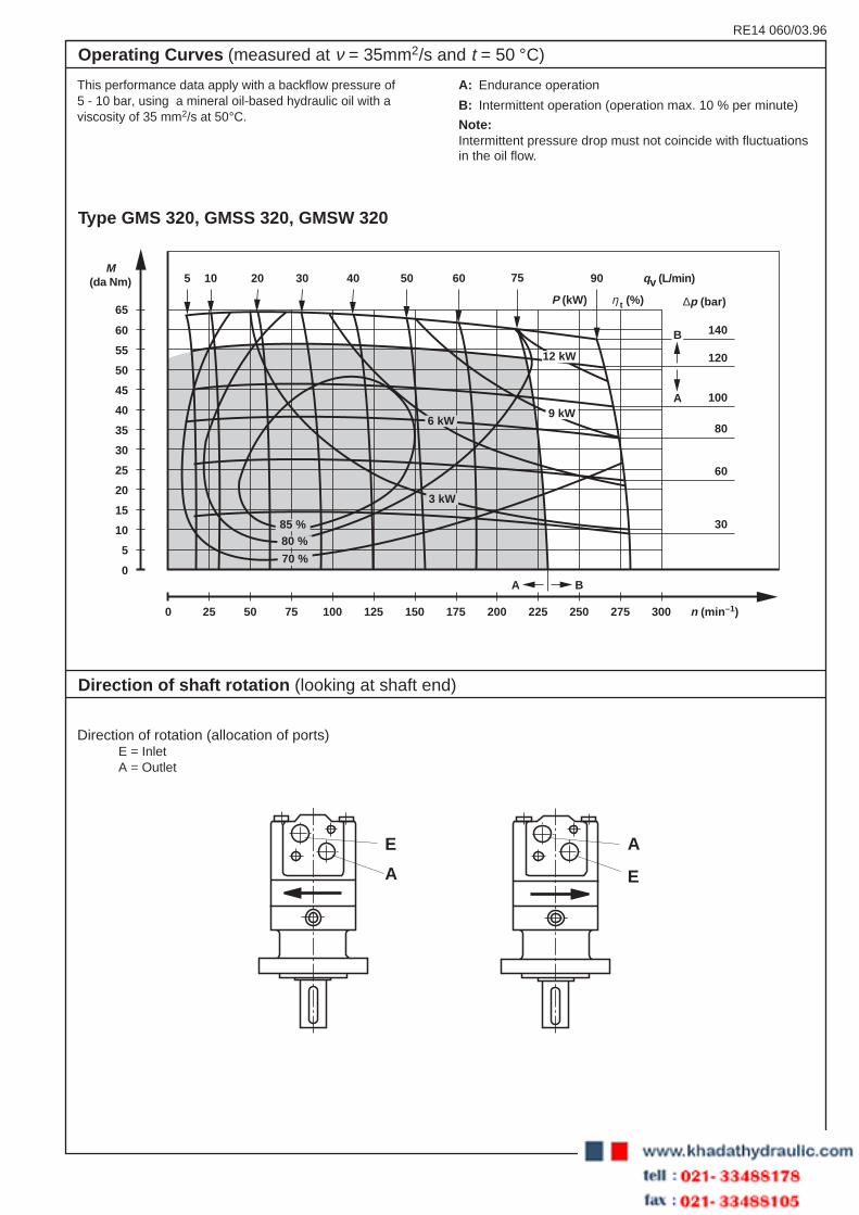
Direction of shaft rotation (looking at shaft end)
Direction of rotation (allocation of ports)E = InletA = Outlet
E
A E
A
Type GMS 320, GMSS 320, GMSW 320
This performance data apply with a backflow pressure of5 - 10 bar, using a mineral oil-based hydraulic oil with aviscosity of 35 mm2/s at 50°C.
A: Endurance operation
B: Intermittent operation (operation max. 10 % per minute)
Note:Intermittent pressure drop must not coincide with fluctuationsin the oil flow.
Operating Curves (measured at ν = 35mm2/s and t = 50 °C)
0 300
5
10 20 30 40 505 75 90
30
0
M(da Nm) qv (L/min)
∆p (bar)
n (min –1)
P (kW) η t (%)
A B
60
80
140
65
60
25
120
A
B
10
15
20
25
30
35
40
45
50
55
60
50 75 100 125 150 175 200 225 250 275
100
85 %80 %
70 %
3 kW
6 kW9 kW
12 kW
RE 14 060/03.96
10/26 Hydraulik Nord
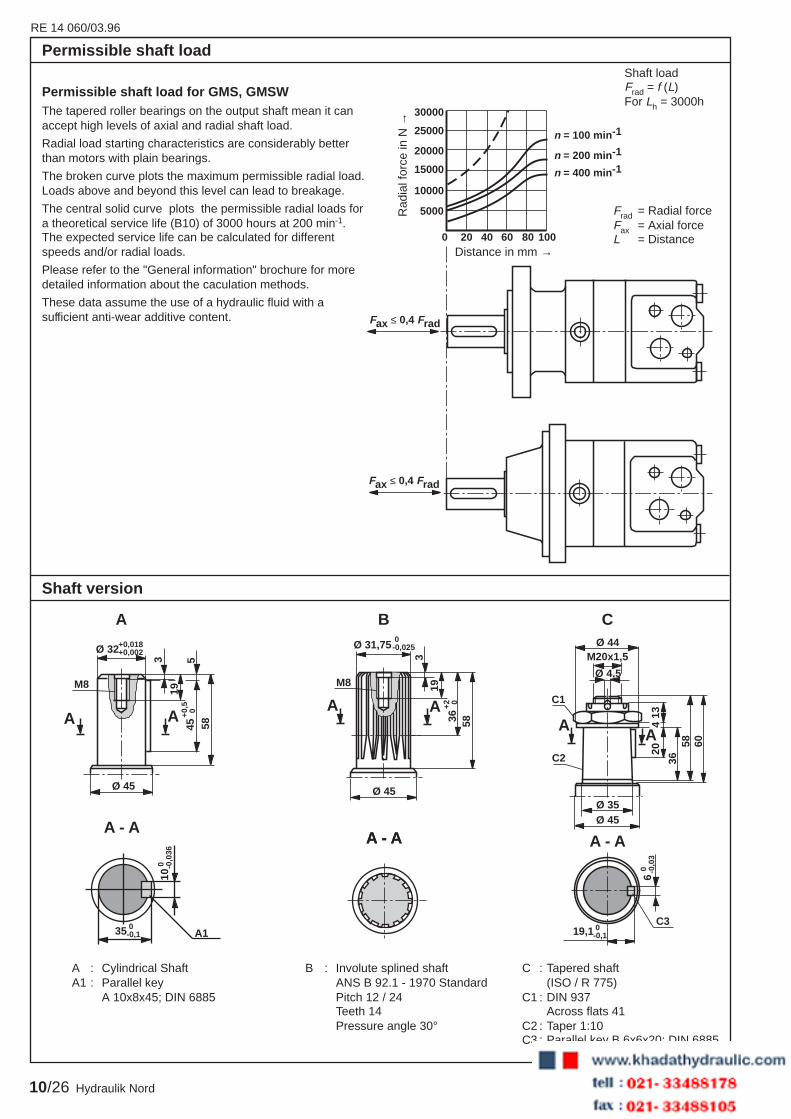
Shaft loadFrad = f (L)For Lh = 3000h
A : Cylindrical Shaft B : Involute splined shaft C : Tapered shaftA1 : Parallel key ANS B 92.1 - 1970 Standard (ISO / R 775)
A 10x8x45; DIN 6885 Pitch 12 / 24 C1 : DIN 937Teeth 14 Across flats 41Pressure angle 30° C2 : Taper 1:10
C3 : Parallel key B 6x6x20; DIN 6885
Shaft version
4
A - A
A135 0-0,1
10 0 -0
,036
19,1 0-0,1
6 0 -0
,03
Ø 32+0,018+0,002
45+0
,5 0
M8
Ø 45
58
19
3 5
A A
A
AA
Ø 45
58 60
1320
36
Ø 35
Ø 44
Ø 4,5
M20x1,5
C1
C2
C3
A - A
CB
A - AA - A
M8
A A
Ø 45
Ø 31,75 0-0,025
36+2 0
58
193
Permissible shaft load
Fax ≤ 0,4 Frad
Fax ≤ 0,4 Frad
30000
25000
20000
15000
10000
5000
n = 100 min -1
n = 200 min -1
n = 400 min -1
0 20 40 60 80 100
Permissible shaft load for GMS, GMSWThe tapered roller bearings on the output shaft mean it canaccept high levels of axial and radial shaft load.
Radial load starting characteristics are considerably betterthan motors with plain bearings.
The broken curve plots the maximum permissible radial load.Loads above and beyond this level can lead to breakage.
The central solid curve plots the permissible radial loads fora theoretical service life (B10) of 3000 hours at 200 min-1.The expected service life can be calculated for differentspeeds and/or radial loads.
Please refer to the "General information" brochure for moredetailed information about the caculation methods.
These data assume the use of a hydraulic fluid with asufficient anti-wear additive content.
Rad
ial f
orce
in N
→
Frad = Radial forceFax = Axial forceL = Distance
Distance in mm →

RE14 060/03.96
11/26Hydraulik Nord
Ø82,5+ 0,05 0
L
L2
L15±
0,6
68±0
,327
±0,3
22±0
,3
66±0
,3
6,1±
0,3
1x45
°
58
18±0
,319
±0,3
R1
T
E
A
16±0,316±0,3
21±0,3 21±0,3
max. 53 max. 55
57
52
Ø10
6,4±
0,3
max
. 131
13,5
M8
max.
104
E: M10; 12,5 deep
A: Available thread connections can be found on page 3
T: Available thread connections can be found on page 3(Drain connection)
Type L L1 L2
GMS 80 169 11 125
GMS 100 172 14 128
GMS 125 175 17 131
GMS 160 180 22 136
GMS 200 186 27,5 141,5
GMS 250 192 34 148
GMS 320 202 44 158
Unit Dimensions: Standard motor Type GMS (Dimensions in mm)

RE 14 060/03.96
12/26 Hydraulik Nord
max. 139
13,5±1
max
. 139
M8
Ø160±0,4
R12
16±0,316±0,3
21±0,3 21±0,3
L
L2
L127
±1
43,2
±1
8+1 R6
31
5±0,
6
22±1
1x45
°
T
E
A
19+0
,516
103±
1
R1
58±1
max. Ø73
Ø125-0,063
16°
max. 53 max. 55
57
Type L L1 L2
GMSW 80 132 11 88
GMSW 100 135 14 91
GMSW 125 138 17 94
GMSW 160 143 22 99
GMSW 200 149 27,5 104,5
GMSW 250 155 34 111
GMSW 320 165 44 121
Unit Dimensions: Wheel motor Type GMSW (Dimensions in mm)
E: M10; 12,5 deep
A: Available thread connections can be found on page 3
T: Available thread connections can be found on page 3(Drain connection)
RE14 060/03.96
13/26Hydraulik Nord
5±0,
6
Ø100 0- 0,054
24
16±0,316±0,3
21±0,3 21±0,3
LL2
16L1
27±0
,6
22±0
,6R1 6±
0,2
1x45
°
23
E
T
A
52
max. 55max. 53
57
max
. 146
3040
Ø12
5±0,
3
24
Ø5
Ø4
11
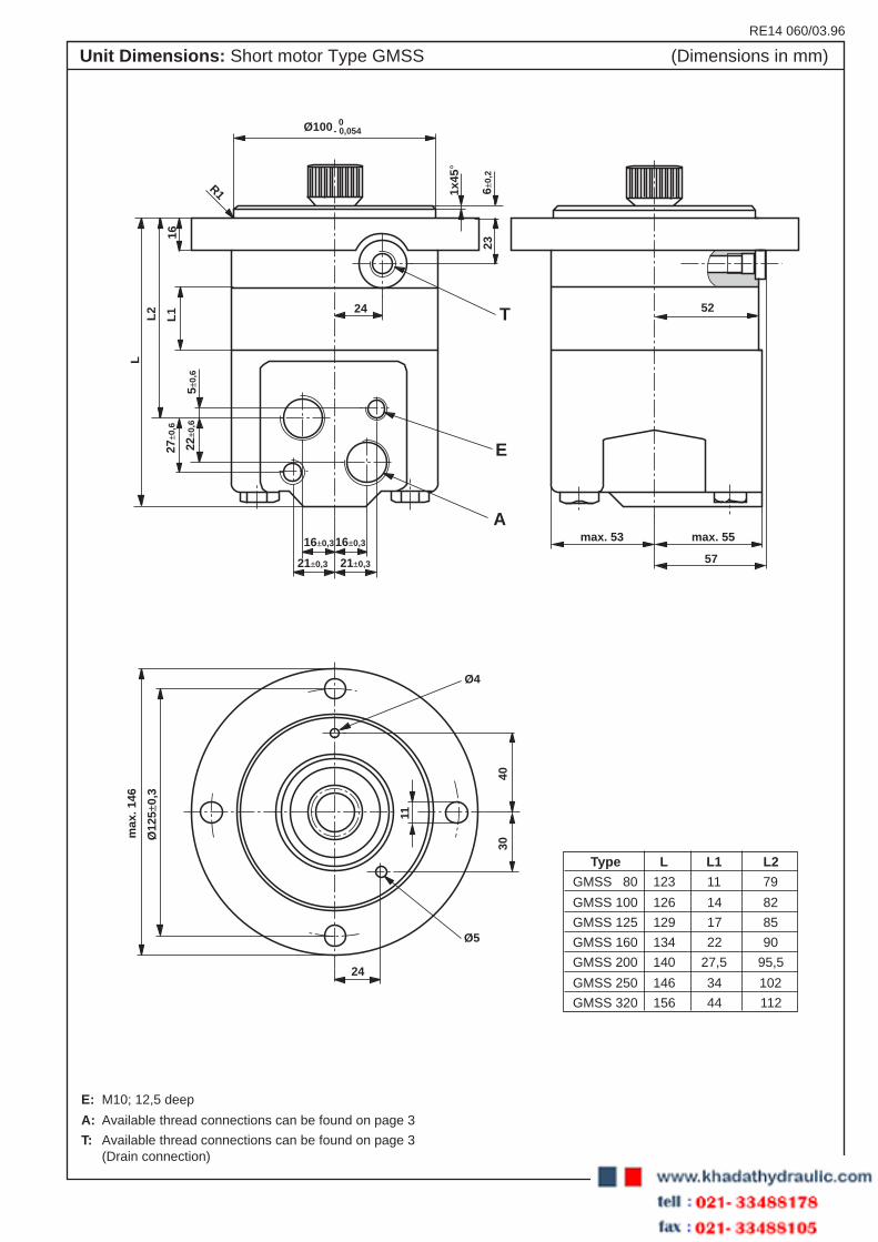
E: M10; 12,5 deep
A: Available thread connections can be found on page 3
T: Available thread connections can be found on page 3(Drain connection)
Type L L1 L2
GMSS 80 123 11 79
GMSS 100 126 14 82
GMSS 125 129 17 85
GMSS 160 134 22 90
GMSS 200 140 27,5 95,5
GMSS 250 146 34 102
GMSS 320 156 44 112
Unit Dimensions: Short motor Type GMSS (Dimensions in mm)
RE 14 060/03.96
14/26 Hydraulik Nord
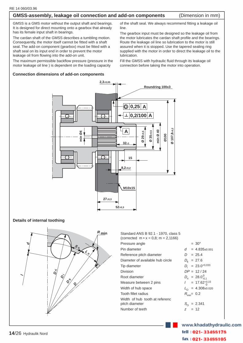
Details of internal toothing
GMSS is a GMS motor without the output shaft and bearings.It is designed for direct mounting onto a gearbox that alreadyhas its female input shaft in bearings.
The cardan shaft of the GMSS describes a tumbling motion.Consequently, the motor itself cannot be fitted with a shaftseal. The add-on component (gearbox) must be fitted with ashaft seal on its input end in order to prevent the motorleakage oil from flowing into the add-on unit.
The maximum permissible backflow pressure (pressure in themotor leakage oil line ) is dependent on the loading capacity
of the shaft seal. We always recommend fitting a leakage oilline.
The gearbox input must be designed so the leakage oil fromthe motor lubricates the cardan shaft profile and the bearings.Route the leakage oil line so lubrication to the motor is stillassured when it is stopped. Use the tapered sealing ringsupplied with the motor in order to direct the leakage oil to thelubrication.
Fill the GMSS with hydraulic fluid through its leakage oilconnection before taking the motor into operation.
2,3±0,05
32±1
27±0,3
52±0,3
0,25
0,2/100
A
A
A
15
M10x15
Ø 1
07,8
±0,2
Ø10
0
min
Ø 4
0
Ø 3
5 ±0,
5
Ø 2
9±0,
5
min
Ø4
8,2±0,2
Roundring 100x3
Connection dimensions of add-on components
d
l
D iD
ri
D fi
D
S oL o
R min Standard ANS B 92.1 - 1970, class 5(corrected m • x = 0,8; m = 2,1166)
Pressure angle = 30°Pin diameter d = 4.835±0.001
Reference pitch diameter D = 25.4
Diameter of available hub circle Dfi = 27.6
Tip diameter Di = 23.0+0,033
Division DP = 12 / 24
Root diameter Dri = 28.0-0,1
Measure between 2 pins I = 17.62+0,15
Width of hub space LO = 4.308±0.020
Tooth fillet radius Rmin= 0.2
Width of hub tooth at referencpitch diameter SO = 2.341
Number of teeth z = 12
GMSS-assembly, leakage oil connection and add-on components (Dimension in mm)
0
0
RE14 060/03.96
15/26Hydraulik Nord
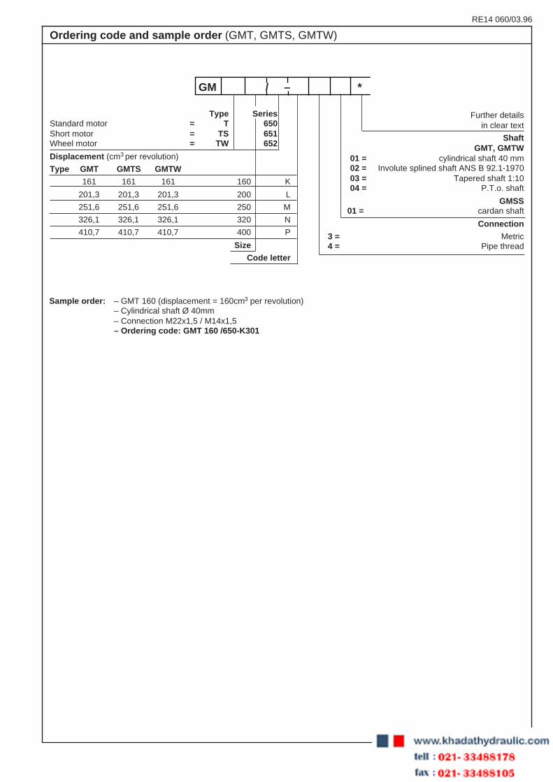
Further detailsin clear text
ShaftGMT, GMTW
01 = cylindrical shaft 40 mm02 = Involute splined shaft ANS B 92.1-197003 = Tapered shaft 1:1004 = P.T.o. shaft
GMSS01 = cardan shaft
Connection
3 = Metric4 = Pipe thread
Ordering code and sample order (GMT, GMTS, GMTW)
Sample order: – GMT 160 (displacement = 160cm3 per revolution)– Cylindrical shaft Ø 40mm– Connection M22x1,5 / M14x1,5– Ordering code: GMT 160 /650-K301
GM / – *
Type SeriesStandard motor = T 650Short motor = TS 651Wheel motor = TW 652
Displacement (cm3 per revolution)
Type GMT GMTS GMTW
161 161 161 160 K
201,3 201,3 201,3 200 L
251,6 251,6 251,6 250 M
326,1 326,1 326,1 320 N
410,7 410,7 410,7 400 P
Size
Code letter
RE 14 060/03.96
16/26 Hydraulik Nord
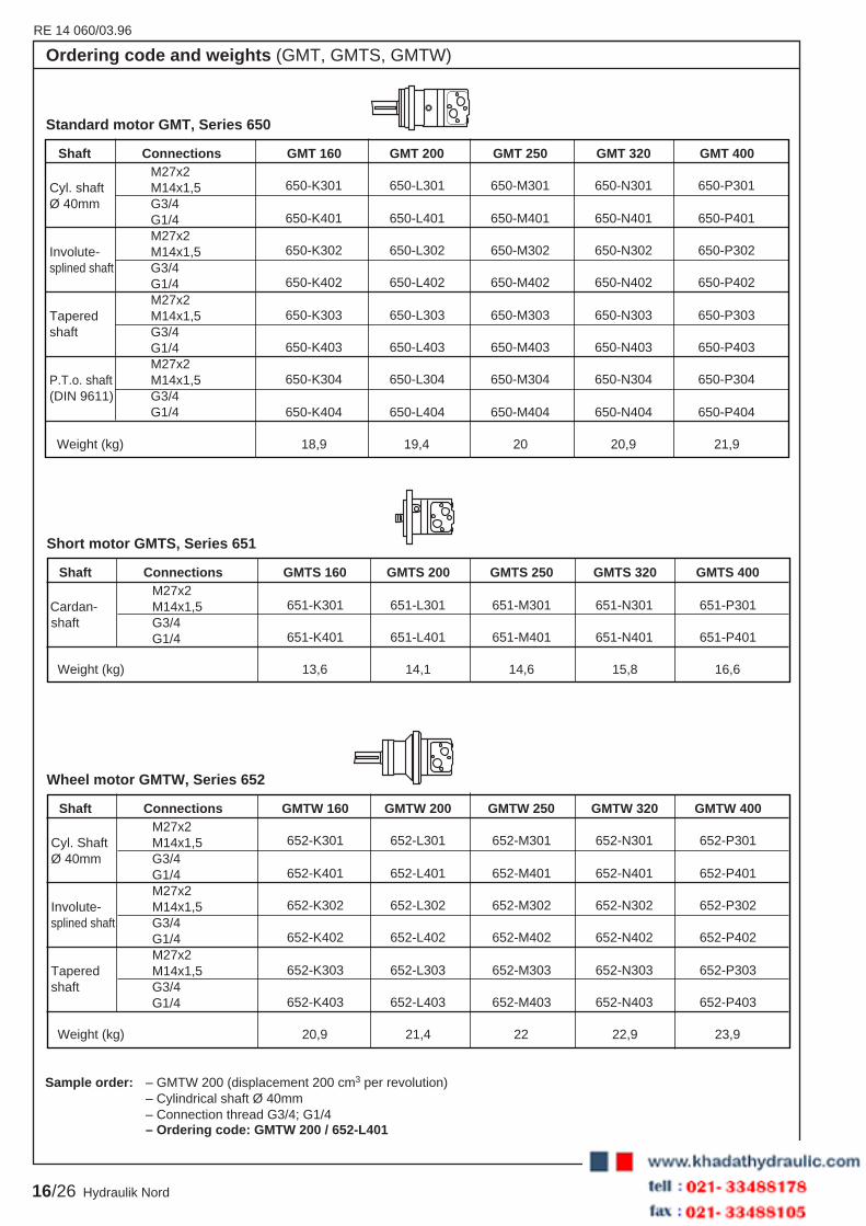
Ordering code and weights (GMT, GMTS, GMTW)
Shaft Connections GMT 160 GMT 200 GMT 250 GMT 320 GMT 400
650-K301 650-L301 650-M301 650-N301 650-P301
650-K401 650-L401 650-M401 650-N401 650-P401
650-K302 650-L302 650-M302 650-N302 650-P302
650-K402 650-L402 650-M402 650-N402 650-P402
650-K303 650-L303 650-M303 650-N303 650-P303
650-K403 650-L403 650-M403 650-N403 650-P403
650-K304 650-L304 650-M304 650-N304 650-P304
650-K404 650-L404 650-M404 650-N404 650-P404
Weight (kg) 18,9 19,4 20 20,9 21,9
M27x2Cyl. shaft M14x1,5Ø 40mm G3/4
G1/4M27x2
Involute- M14x1,5splined shaft G3/4
G1/4M27x2
Tapered M14x1,5shaft G3/4
G1/4M27x2
P.T.o. shaft M14x1,5(DIN 9611) G3/4
G1/4
Standard motor GMT, Series 650
Shaft Connections GMTW 160 GMTW 200 GMTW 250 GMTW 320 GMTW 400
652-K301 652-L301 652-M301 652-N301 652-P301
652-K401 652-L401 652-M401 652-N401 652-P401
652-K302 652-L302 652-M302 652-N302 652-P302
652-K402 652-L402 652-M402 652-N402 652-P402
652-K303 652-L303 652-M303 652-N303 652-P303
652-K403 652-L403 652-M403 652-N403 652-P403
Weight (kg) 20,9 21,4 22 22,9 23,9
M27x2Cyl. Shaft M14x1,5Ø 40mm G3/4
G1/4M27x2
Involute- M14x1,5splined shaft G3/4
G1/4M27x2
Tapered M14x1,5shaft G3/4
G1/4
Wheel motor GMTW, Series 652
Sample order: – GMTW 200 (displacement 200 cm3 per revolution)– Cylindrical shaft Ø 40mm– Connection thread G3/4; G1/4– Ordering code: GMTW 200 / 652-L401
Shaft Connections GMTS 160 GMTS 200 GMTS 250 GMTS 320 GMTS 400
651-K301 651-L301 651-M301 651-N301 651-P301
651-K401 651-L401 651-M401 651-N401 651-P401
Weight (kg) 13,6 14,1 14,6 15,8 16,6
M27x2 Cardan- M14x1,5shaft G3/4
G1/4
Short motor GMTS, Series 651

RE14 060/03.96
17/26Hydraulik Nord
Technical Data: GMT, GMTS, GMTW (For applications outside these parameters, please consult us !)
Motor size 160 200 250 320 400
Geometric displacement cm3 161 201,3 251,6 326,1 410,7
Max. speed min-1 continuous 625 625 500 380 305
intermittent 1) 780 750 600 460 365
Max. torque daNm continuous 47,5 58,5 74,5 96 98
intermittent 1) 54 70 87 112 123
Max. power output kW continuous 27 34 34 34 30
intermittent 1) 32 40 40 40 35
Max. pressure drop bar continuous 210 210 210 210 180
intermittent 1) 240 240 240 240 240
Max. oil flow L/min continuous 100 125 125 125 125
intermittent 1) 125 150 150 150 150
Max. input pressure bar continuous 210
intermittent 1) 250
Max. return pressure without drain line or max.pressure in drain line 2)
(0-100 min-1) bar continuous 75
(100-300 min-1) bar continuous 40
(300-620 min-1) bar continuous 20
(0-780 min-1) bar intermittent 1) 75
Max. return pressure with drain linebar continuous 140
intermittent 1) 175
Max. start pressure with unloaded shaftbar 12 12 12 12 12
Min. start torque at max. pressure dropdaNm continuous 34 43 54 74 78
Min. speed 3) min-1 10 10 10 10 10
1) Intermittent operation: operation max. 10% per minute2) The pressure on the shaft seal is never greater than the
backflow pressure because of the build-in non- returnvalves. In the GMSS, this pressure is determint based onthe technical data of the add-on components
3) You must expect that the motor will run less smoothly atspeeds below those specified here.

RE 14 060/03.96
18/26 Hydraulik Nord
Type GMT 160, GMTS 160, GMTW 160
Type GMT 200, GMTS 200, GMTW 200
This performance data apply with a backflow pressure of5 - 10 bar, using a mineral oil-based hydraulic oil with aviscosity of 35 mm2/s at 50°C.
A: Endurance operation
B: Intermittent operation (operation max. 10 % per minute)
Note:Intermittent pressure drop must not coincide with fluctuationsin the oil flow.
Operating Curves (measured at ν = 35mm2/s and t = 50 °C)
0 800
5
10 20 40 60 80 125
30
0
M(da Nm) qv (L/min)
∆p (bar)
n (min –1)
P (kW) η t (%)
A B
60
90
180
24060
100
100
210
A
B
10
15
20
25
30
35
40
45
50
55
200 300 400 500 600 700
150
125
85 %
80 %
70 %5 kW
10 kW
15 kW
20 kW
25 kW
30 kW
35 kW
0 750
5
10 20 40 60 80 125
30
0
M(da Nm) qv (L/min]
∆p (bar)
n (min –1)
P (kW) η t (%)
A B
60
90
180
24075
100
50
210
A
B
150
120
10
15
20
25
30
35
40
45
50
55
60
65
70
100 150 200 250 300 350 400 450 500 550 600 650 700
150
70 %80 %
85 %87 %5 kW
10 kW
15 kW
20 kW
25 kW
30 kW
35 kW 40 kW
RE14 060/03.96
19/26Hydraulik Nord
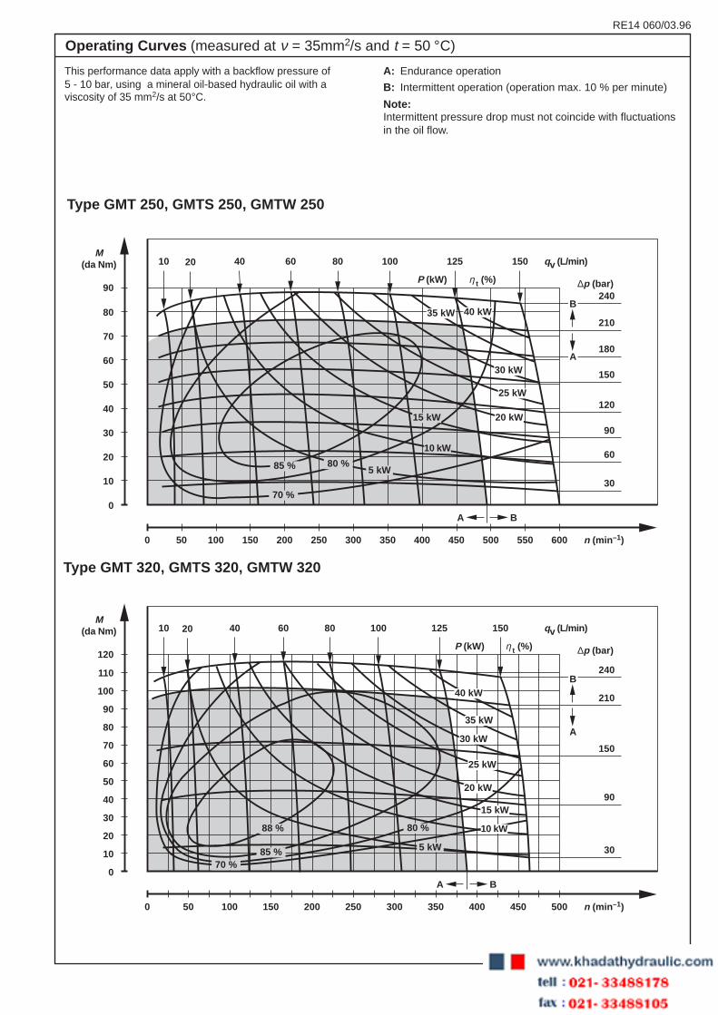
Type GMT 320, GMTS 320, GMTW 320
Type GMT 250, GMTS 250, GMTW 250
This performance data apply with a backflow pressure of5 - 10 bar, using a mineral oil-based hydraulic oil with aviscosity of 35 mm2/s at 50°C.
A: Endurance operation
B: Intermittent operation (operation max. 10 % per minute)
Note:Intermittent pressure drop must not coincide with fluctuationsin the oil flow.
Operating Curves (measured at ν = 35mm2/s and t = 50 °C)
0 600
10
10 20 40 60 80 125
30
0
M(da Nm) qv (L/min)
∆p (bar)
n (min –1)
P (kW) η t (%)
A B
60
90
180
24090
100
50
210
A
B
150
120
150
20
30
40
50
60
70
80
100 150 200 250 300 350 400 450 500 550
40 kW35 kW
30 kW
25 kW
20 kW15 kW
10 kW
5 kW85 %
70 %
80 %
0 500
10
10 20 40 60 80 125
30
0
M(da Nm) qv (L/min)
∆p (bar)
n (min –1)
P (kW) η t (%)
A B
90
240
120
100
210
A
B
150
150
20
30
40
50
60
70
80
90
100
110
50 100 150 200 250 300 350 400 450
70 %85 %
88 % 80 %
40 kW
35 kW
30 kW
25 kW
20 kW
15 kW
10 kW
5 kW

RE 14 060/03.96
20/26 Hydraulik Nord
E
A E
A
Direction of rotation (allocation of ports)E = InletA = Outlet
Type GMT 400, GMTS 400, GMTW 400
Direction of shaft rotation (looking at shaft end)
This performance data apply with a backflow pressure of5 - 10 bar, using a mineral oil-based hydraulic oil with aviscosity of 35 mm2/s at 50°C.
A: Endurance operation
B: Intermittent operation (operation max. 10 % per minute)
Note:Intermittent pressure drop must not coincide with fluctuationsin the oil flow.
Operating Curves (measured at ν = 35mm2/s and t = 50 °C)
0 375
10
10 20 40 60 80 125
30
0
M(da Nm) qv (L/min)
∆p (bar)
n (min –1)
P (kW) η t (%)
A B
90
210130
100
180
A
B
150
150
25
20
30
40
50
60
70
80
90
100
110
120
50 75 100 125 150 175 200 225 250 275 300 325 350
120
60
35 kW
30 kW
25 kW
20 kW
15 kW
10 kW
5 kW
89 %
85 %87 %
80 % 70 %
RE14 060/03.96
21/26Hydraulik Nord
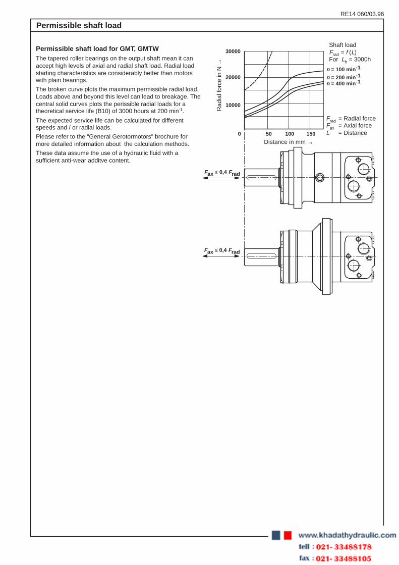
Permissible shaft load
0 50 100 150
10000
20000
30000
n = 100 min -1
n = 200 min -1
n = 400 min -1
Fax ≤ 0,4 Frad
Fax ≤ 0,4 Frad
Permissible shaft load for GMT, GMTWThe tapered roller bearings on the output shaft mean it canaccept high levels of axial and radial shaft load. Radial loadstarting characteristics are considerably better than motorswith plain bearings.
The broken curve plots the maximum permissible radial load.Loads above and beyond this level can lead to breakage. Thecentral solid curves plots the perissible radial loads for atheoretical service life (B10) of 3000 hours at 200 min-1.
The expected service life can be calculated for differentspeeds and / or radial loads.
Please refer to the "General Gerotormotors" brochure formore detailed information about the calculation methods.
These data assume the use of a hydraulic fluid with asufficient anti-wear additve content.
Frad = Radial forceFax = Axial forceL = Distance
Shaft loadFrad = f (L)For Lh = 3000h
Rad
ial f
orce
in N
→
Distance in mm →

RE 14 060/03.96
22/26 Hydraulik Nord
Shaft version
A143 -0,2
12-0
,043
A - A
Ø 40
70+0
,5 0
M12
Ø 4582
28±0
,16
4 5 ±0,
5
A A
A
M12
A A
Ø 45
Ø 38,1-0,025
56+2 0
82
28±0
,6
4
A - A
45°45°
B
A A
A - AA - A
A A
38±0
,25
8254
2234
4
Ø45
DIN 937SW46
1:10
Ø56M30x2
Ø7Ø6
12 0 -0
,043
25,14 0-0,2
C1 12x8x28 DIN 6885
76±1
Ø45
Ø34,85-0,12
Ø29,4±0,1
60°
R6,7
R5
102
45°
Ø28
,14-
0,2 1
)
8,64-0,11
C D
+0,018+0,002
7
A: Cylindrical shaft B: Involute splined shaftA1: Parallel key A12x18x70 ANS B 92.1 - 1970
Pitch12 / 24Teeth 17Pressure angle 30°
C: Tapered shaft D: P.T.o. shaft(ISO/R 775) DIN 9611 Form 1
C1: Parallel key (ISO/R 500 without pin hole)1) Deviates from DIN 9611
RE14 060/03.96
23/26Hydraulik Nord
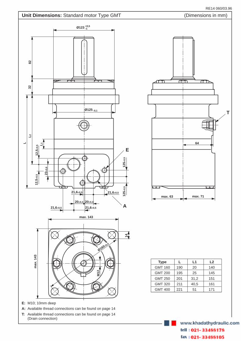
Unit Dimensions: Standard motor Type GMT (Dimensions in mm)
Ø123
Ø125
+0,5-1
-0,1
21,6±0,5 21,6±0,5
20±0,320±0,3
21,6±0,521,6±0,5
max. 143
max
. 143
125±
0,5
125±
0,5
A
E
T
L
L2
82
L1
12,5
±0,5
12,5
±0,5 23
±0,6
32
max. 63 max. 71
64
14
Ø160±0,4
M12
Type L L1 L2
GMT 160 190 20 140
GMT 200 195 25 145
GMT 250 201 31,2 151
GMT 320 211 40,5 161
GMT 400 221 51 171
E: M10; 10mm deep
A: Available thread connections can be found on page 14
T: Available thread connections can be found on page 14(Drain connection)

RE 14 060/03.96
24/26 Hydraulik Nord
max. 180
max
. 180
18
Ø200±0,4
max. 63
75
max. 71
21,6 ±0,5 21,6 ±0,5
21,6 ±0,5 21,6 ±0,5
20 ±0,320 ±0,3
12,5
±0,
5
12,5
±0,
5
E T
A
12,5
±0,
5
12,5
±0,
5
23 ±
0,6
L
L2
L1
82
99
8
R1,2
R1,2
45°
Ø123
Ø125-0,1
Ø172-0,063
+0,5-1
Ø160-0,063
M12
E: M10; 10mm deep
A: Available thread connections can be found on page 14
T: Available thread connections can be found on page 14(Drain connection)
Type L L1 L2
GMTW 160 123 20 73
GMTW 200 128 25 78
GMTW 250 134 31,2 84
GMTW 320 144 40,5 94
GMTW 400 154 51 104
Unit Dimensions: Wheel motor Type GMTW (Dimensions in mm)

RE14 060/03.96
25/26Hydraulik Nord
Ø125 -0,063
28
E
A21,6±0,5 21,6±0,5
20±0,320±0,3
21,6±0,5 21,6±0,5
12,5
±0,5
12,5
±0,5
12,5
±0,5
12,5
±0,5
23±0
,6
L
L2 L1
18
31
70T
max. 71max. 63
14
50
28
max. 185
R44
Ø160±0,4
20°
Type L L1 L2
GMTS 160 145 20 95
GMTS 200 150 25 100
GMTS 250 156 31,2 106
GMTS 320 166 40,5 116
GMTS 400 176 51 126
Unit Dimensions: Short motor Type GMTS (Dimensions in mm)
E: M10; 10mm deep
A: Available thread connections can be found on page 14
T: Available thread connections can be found on page 14(Drain connection)
RE 14 060/03.96
26/26 Hydraulik Nord
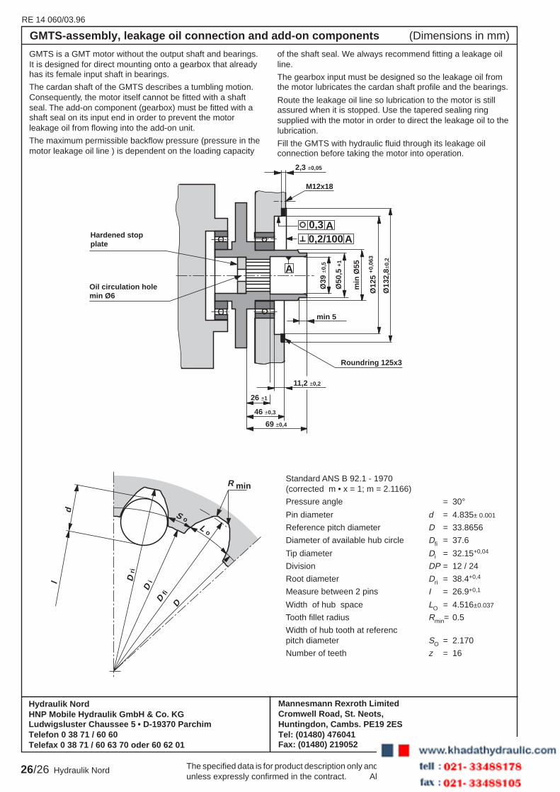
GMTS-assembly, leakage oil connection and add-on components (Dimensions in mm)
GMTS is a GMT motor without the output shaft and bearings.It is designed for direct mounting onto a gearbox that alreadyhas its female input shaft in bearings.
The cardan shaft of the GMTS describes a tumbling motion.Consequently, the motor itself cannot be fitted with a shaftseal. The add-on component (gearbox) must be fitted with ashaft seal on its input end in order to prevent the motorleakage oil from flowing into the add-on unit.
The maximum permissible backflow pressure (pressure in themotor leakage oil line ) is dependent on the loading capacity
of the shaft seal. We always recommend fitting a leakage oilline.
The gearbox input must be designed so the leakage oil fromthe motor lubricates the cardan shaft profile and the bearings.
Route the leakage oil line so lubrication to the motor is stillassured when it is stopped. Use the tapered sealing ringsupplied with the motor in order to direct the leakage oil to thelubrication.
Fill the GMTS with hydraulic fluid through its leakage oilconnection before taking the motor into operation.
26 ±1
11,2 ±0,2
46 ±0,3
69 ±0,4
2,3 ±0,05
M12x18
A
AA0,3
0,2/100
min 5Ø
39 ±
0,5
Ø50
,5 +
1
min
Ø55
Ø12
5 +0
,063
Ø13
2,8±
0,2
Roundring 125x3
Oil circulation holemin Ø6
Hardened stopplate
d
l
D iD
ri
D fi
D
S oL o
R minStandard ANS B 92.1 - 1970(corrected m • x = 1; m = 2.1166)
Pressure angle = 30°Pin diameter d = 4.835± 0.001
Reference pitch diameter D = 33.8656
Diameter of available hub circle Dfi = 37.6
Tip diameter Di = 32.15+0,04
Division DP = 12 / 24
Root diameter Dri = 38.4+0,4
Measure between 2 pins I = 26.9+0,1
Width of hub space LO = 4.516±0.037
Tooth fillet radius Rmin= 0.5
Width of hub tooth at referencpitch diameter SO = 2.170
Number of teeth z = 16
Mannesmann Rexroth LimitedCromwell Road, St. Neots,Huntingdon, Cambs. PE19 2ESTel: (01480) 476041Fax: (01480) 219052
The specified data is for product description only and may not be deemed to be guaranteedunless expressly confirmed in the contract. All rights reserved – Subject to revision
Hydraulik NordHNP Mobile Hydraulik GmbH & Co. KGLudwigsluster Chaussee 5 • D-19370 ParchimTelefon 0 38 71 / 60 60Telefax 0 38 71 / 60 63 70 oder 60 62 01