re: submittal data for aurora end suction pumps - mrwa · re: submittal data for aurora end suction...
TRANSCRIPT
Barr Engineering Co. 4300 MarketPointe Drive, Suite 200, Minneapolis, MN 55435 952.832.2600 www.barr.com
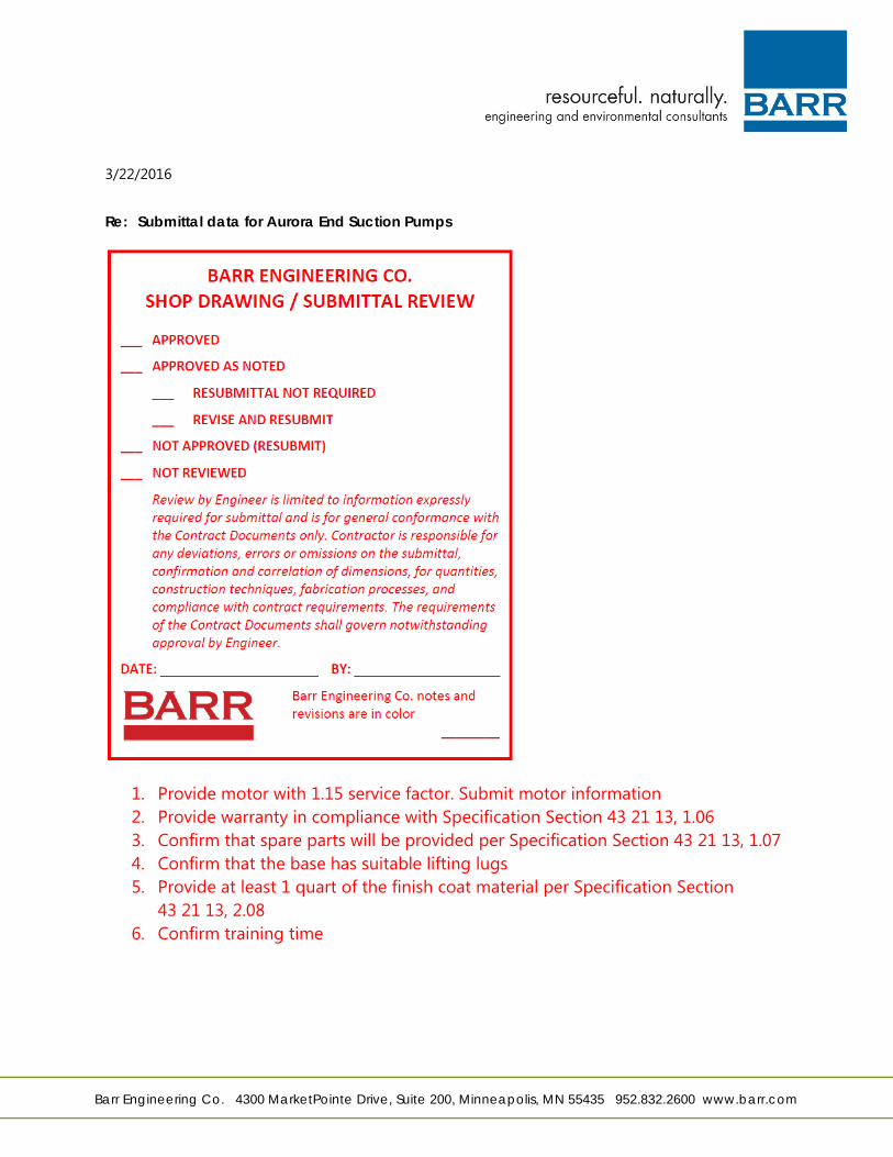
3/22/2016
Re: Submittal data for Aurora End Suction Pumps
1. Provide motor with 1.15 service factor. Submit motor information 2. Provide warranty in compliance with Specification Section 43 21 13, 1.06 3. Confirm that spare parts will be provided per Specification Section 43 21 13, 1.07 4. Confirm that the base has suitable lifting lugs 5. Provide at least 1 quart of the finish coat material per Specification Section
43 21 13, 2.08 6. Confirm training time

W.W. GOETSCH ASSOCIATES, INC. 5250 West 74th Street Minneapolis, Minnesota 55439
SUBMIITALDATA FOR
NO. OF PRINTS
For Approval
(952) 831-4340/fax: (952) 831-2357 AURORA END SUCTION PUMPS Final
Job: New Brighton WTP #1 Service Engineer:
Temporary Low Zone Booster Pumps Barr Engineering
Contractor: TBD Sold To: Ban Engineering Reference: Section 43 21 13 Temporary Centrifugal Pumps
PUMP No. ofUnits 2 Model Aurora 3804 Size 8x10x13.5 GPM 2083 TDH 43' RPM 1200
Rotation: LHD
Connections: ~ Flanged D Threaded
~ 125# 0250#
Lubrication: D Grease D Oil
Stuffing Box: ~ Mechanical Seal
• D Packing D Lantern Ring
Construction: ~ Standard Fitted D Bronze Fitted
Case: Cast Iron Impeller: SS Shaft: steel Sleeve: SS Case Ring: n/a Impeller Ring: n/a Channel Ring: n/a Spacer: n/a
By: Bryan Goehring
PUMP SUBMITTAL 03132001
MOTOR
HP: 40 Phase: 3 Hertz: 60 Volts: 460 RPM: 1200 Frame: 364
Enclosure: ~ ODP D TEFC D XProof
D Vertical
~ Horizontal
D Part Winding
~ High Efficiency
~ Aurora to Furnish
D Others to Furnish
D Factory Choice
Mfg: _M_ai_·a_th_o_n _____ _
NSF/ANSI 372 Cerified
Date: 03/21/2016 Office:
WWGJob#: BG22164
Base:
D ~ D D D D
PO#: 031816
OPTIONS
included Steel Drip Rim Steel Form Fabricated Steel Cast Iron Ring Type Fab. Steel Ring Type
D Close Coupled Unit D Pedestal Unit
Coupling: Flex
M~: ~~~~~~~~~ Size
Test:
D D D
~---------
0 Spacer ~ Guard
Certified Performance Hydrostatic Test VIP Test
SPECIAL REQUIREMENTS:
W. W. Goetsch Associates, Inc.
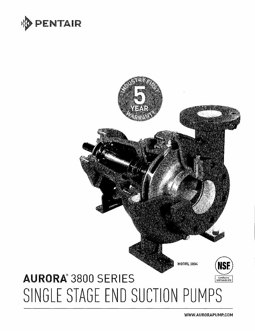
MODEL3804 @ AURORA® 3800 SERI ES N~~~:~~1~72
SINGLE STAGE END SUCT ON PUMPS WWW.AURORAPUMP.COM

2
"' ~ :;
S!NGl..lE SiT~GE ~~D SUGiTIQN FWMF!S
AURORA® 3800 SERI S
Single Stage End Suction Pumps Capacities to 4200 gpm (954 m3/hr) Heads to 520 feet (158 meters) Temperatures to 300°F (149°C)
Liquid handling requirements are much more involved than they were years ago. The variety of liquids being handled has increased along with temperatures and pressures. Today's installations demand quiet smooth running pumps with long life. Aurora's 90 years of experience with design, sales and manufacturing of centrifugal pumps has led to the 3800 Series. These modern pumps with a clean, straightforward design were developed with maximum interchangeability in mind. Aurora's highly reliable 3800 pumps offer an economical solution to your liquid handling problems.
• Offered in two models: - 3801 Close coupled - 3804 Flexible coupled-frame mounted
• 316SSTimpeller
• 316 SST shaft sleeve
• Double volute on 4" discharge and larger to reduce bearing loads
• Gauge taps on suction and discharge on flanged models
• 4 Power frame sizes
• Casing feet for easy back pullout
• Regreaseable bearings [3804 only]
• Coupling guard [flex coupled design]
• Formed steel base [flex coupled design]

PENTAIR Item number Service Quantity Quote number
Operating Conditions
Flow, rated
Customer Project name
: Default
:Water :2
: Barr Engineering
Size Stages
Based on curve number Date last saved
Liquid
Liquid type
Pump Performance Datasheet Encompass 2.0 - 16.1.0.0
: 3800 - 8x10x13.5 : 1 : H83-8x10x13.5-1150 Rev O : 21 Mar 2016 3:09 PM
:Water
Differential head I pressure, rated (requested)
Differential head I pressure, rated (actual) Suction pressure, rated I max
: 2,083.0 USgpm : 43.00 ft
: 43.45 ft : 0.00 I 0.00 psi.g :Ample
Additional liquid description Solids diameter, max
Solids concentration, by volume Temperature, max
: 0.00 in : 0.00 %
NPSH available, rated
Frequency
Performance
Speed, rated Impeller diameter, rated Impeller diameter, maximum
Impeller diameter, minimum Efficiency
NPSH required I margin required nq (imp. eye flow) I S (imp. eye flow)
Minimum Continuous Stable Flow Head, maximum, rated diameter Head rise to shutoff
Flow, best eff. point Flow ratio, rated I BEP Diameter ratio (rated I max)
Head ratio (rated dia I max dia) Cq/Ch/Ce/Cn [ANSI/HI 9.6.7-2010] Selection status
36
a. 27 .c
" " 18
0 0..
9
0
100
90 13,50in
80
70
60 11.44 in
"" ' 'O 50 "' " I
40
30 9.50 in
20
10
0
16
"" ' :!: 8 (/) 0.. z
0 0 500
PENTAIR
1,000
: 60 Hz
: 1150 rpm
: 11.44 in : 13.50 in
: 9.50 in : 72.58 % : 9.05 / 0.00 ft
: 42 I 205 Metric units : 545.7 USgpm : 58.90 ft
: 36.99 %
: 1,776.5 USgpm : 117.26 % : 84.72 %
: 57.62 % : 1.00/ 1.00/ 1.00/ 1.00 : Acceptable
Fluid density, rated I max
Viscosity, rated Vapor pressure, rated
Material
Material selected
Pressure Data
Maximum working pressure Maximum allowable working pressure Maximum allowable suction pressure
Hydrostatic test pressure
Driver & Power Data
Driver sizing specification
Margin over specification Service factor Power, hydraulic
Power, rated Power, maximum, rated diameter Minimum recommended motor rating
-----+-----r-- Power
-- Minimum Continuous Stable Flow -- Max allowable flow
Preferred operating region
: 68.00 deg F
: 1.000 / 1.000 SG
: 1.00 cP : 0.34 psi.a
: Standard
: 25.49 psi.g : 175.0 psi.g : 175.0 psi.g
: 125.0 psi.g
: Max Power : 0.00 % : 1.00
: 22.61 hp :31.16hp : 32.06 hp : 40.00 hp/ 29.83 kW
Curve efficiencies are typical. For guaranteed values, contact factory
1,500 2,000 Flow-USgpm
AURORA PUMP 800 AIRPORT ROAD · NORTH
AURORA, ILLINOIS 60542 WWW.AURORAPUMP.COM
2,500
77
NPSHrl
I 3,000 3,500 4,000
PHONE: +1-630-859-7000 ·FAX:

PENTAIR Customer : Barr Engineering
Item number
Quote number
Pump Qty Description
Default
2 Series 3800- Bx10x13.5
Pump information
Parameters
Project name
Size I Stages
Pump speed
Impeller Diameter Selection Criteria: Impeller diameter calculated from 2083 USgpm and 43 Ft
Flow: 2083.00 USgpm
Head: 43.00 Ft
Impeller diameter: 11.4375 inches - based on curve data
Power: 40.00 Hp
Speed: 1150 RPM
Suction Pressure (max): 175.00 psi
Pump model: Model 3804, Horizontal flex-coupled pumps
Rotation: Right
Paint: Standard blue paint
Driver
Shaft Grounding Ring: Not Specified
Materials of Construction
Customer Technical Offer Encompass 2.0 - 16.1.0.0
3800 - 8x10x13.5 / 1
1150 rpm
Pump: 8 X 10 X 13.5- End Suction, Model 3804, Frame range - 286-447TS, Power frame - 21A, Stainless Steel Fitted
Casing: Cast iron, ASTM A48
Impeller: Stainless steel, 316
Shaft: Steel, AISI C1045
Case wear ring: None
Motor bracket: Cast iron, ASTM A48
Power frame: Cast iron, ASTM A48
Sealing: Mechanical seal, John Crane, Type 21, hot water 225° F max
Sleeve: Stainless steel, AISI 316
Pump options
Base: Steel Base 364T Frame
Coupling: Factory Choice Coupling, 364T Frame
Drip pan: No
Bearing lubrication: Grease
Flushing lines: None
Coating: No
Motor Qty Description
2
Pump information
Driver
Motor Frame: 364T
Motor: 40hp@ 1200 RPM, 3 Ph, 230/460 Volts, 364T Frame, ODP Enclosure, premium efficiency, Marathon
Selected Motor Parameters
Power: 40hp
Phase:3
Frequency: 60 Hz
Voltage: 230/460V
Enclosure: ODP
PENTAIR AURORA PUMP
800 AIRPORT ROAD · NORTH AURORA, ILLINOIS 60542
WWW.AURORAPUMP.COM
: +1-630-859-7000 . :
PENTAIR Customer Project name
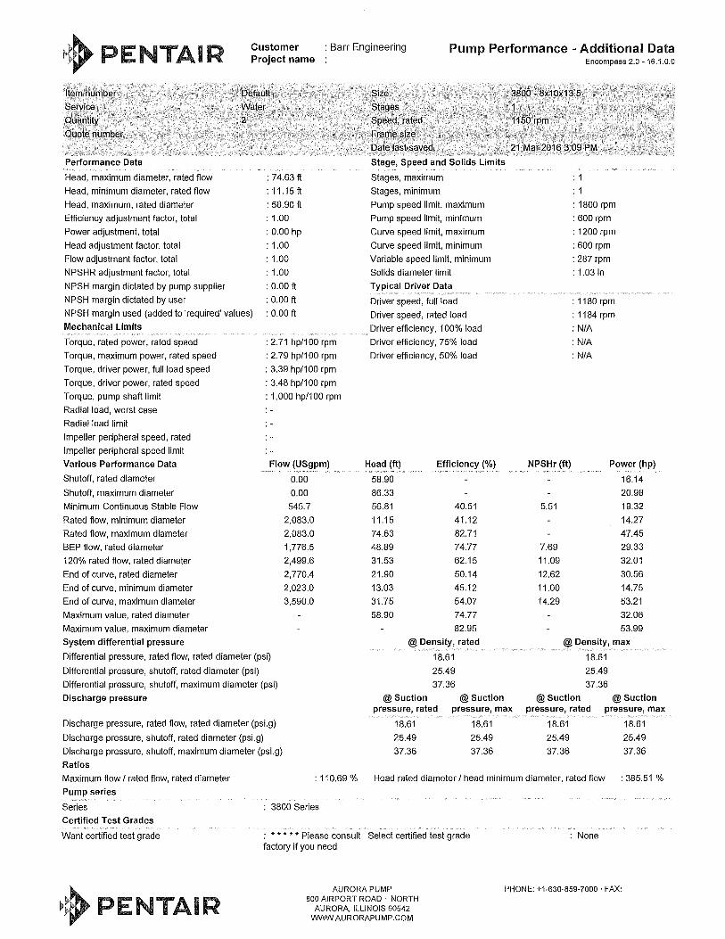
: Barr Engineering Pump Performance - Additional Data
Item number
Service
Quantity
Quote number
Performance Data
Head, maximum diameter, rated flow
Head, minimum diameter, rated flow
Head, maximum, rated diameter
Efficiency adjustment factor, total
Power adjustment, total
Head adjustment factor, total
Flow adjustment factor, total
NPSHR adjustment factor, total
NPSH margin dictated by pump supplier
NPSH margin dictated by user
: Default
:Water
:2
: 74.63 ft
: 11.15 ft
: 58.90 ft
: 1.00
: 0.00 hp
: 1.00
: 1.00
: 1.00
: 0.00 ft
: 0.00 ft
NPSH margin used (added to 'required' values)
Mechanical Limits
: 0.00 ft
Torque, rated power, rated speed
Torque, maximum power, rated speed
Torque, driver power, full load speed
Torque, driver power, rated speed
Torque, pump shaft limit
Radial load, worst case
Radial load limit
Impeller peripheral speed, rated
Impeller peripheral speed limit
Various Performance Data
Shutoff, rated diameter
Shutoff, maximum diameter
Minimum Continuous Stable Flow
Rated flow, minimum diameter
Rated flow, maximum diameter
BEP flow, rated diameter
120% rated flow, rated diameter
End of curve, rated diameter
End of curve, minimum diameter
End of curve, maximum diameter
Maximum value, rated diameter
Maximum value, maximum diameter
System differential pressure
: 2.71 hp/100 rpm
: 2.79 hp/100 rpm
: 3.39 hp/100 rpm
: 3.48 hp/100 rpm
: 1,000 hp/100 rpm
Flow (USgpm)
0.00
0.00
545.7
2,083.0
2,083.0
1,776.5
2,499.6
2,770.4
2,023.0
3,590.0
Differential pressure, rated flow, rated diameter (psi)
Differential pressure, shutoff, rated diameter (psi)
Differential pressure, shutoff, maximum diameter (psi)
Discharge pressure
Size
Stages
Speed, rated
Frame size
Date last saved
Stage, Speed and Solids Limits
Stages, maximum
Stages, minimum
Pump speed limit, maximum
Pump speed limit, minimum
Curve speed limit, maximum
Curve speed limit, minimum
Variable speed limit, minimum
Solids diameter limit
Typical Driver Data
Driver speed, full load
Driver speed, rated load
Driver efficiency, 100% load
Driver efficiency, 75% load
Driver efficiency, 50% load
Head (ft)
58.90
86.33
56.81
11.15
74.63
48.89
31.53
21.90
13.03
31.75
58.90
Efficiency (%)
40.51
41.12
82.71
74.77
62.15
50.14
45.12
54.07
74.77
82.95
@Density, rated
18.61
25.49
37.36
@Suction @Suction
Encompass 2.0 - 16.1.0.0
: 3800 - 8x10x13.5
: 1 : 1150 rpm
: 21 Mar 2016 3:09 PM
: 1
: 1
: 1800 rpm
: 600 rpm
: 1200 rpm
: 600 rpm
: 287 rpm
: 1.03 in
: 1180 rpm
: 1184 rpm
: N/A
: N/A
: N/A
NPSHr (ft) Power (hp)
16.14
20.98
19.32
14.27
47.45
29.33
32.01
30.56
14.75
53.21
32.06
53.99
5.51
7.69
11.09
12.62
11.00
14.29
@Density, max
18.61
25.49
37.36
@Suction @Suction pressure, rated pressure, max pressure, rated pressure, max
Discharge pressure, rated flow, rated diameter (psi.g)
Discharge pressure, shutoff, rated diameter (psi.g)
Discharge pressure, shutoff, maximum diameter (psi.g)
Ratios
18.61
25.49
37.36
18.61
25.49
37.36
18.61 18.61
25.49 25.49
37.36 37.36
Maximum flow I rated flow, rated diameter
Pump series
: 110.69 % Head rated diameter I head minimum diameter, rated flow : 385.51 %
Series
Certified Test Grades
Want certified test grade
PENTAIR
3800 Series
: * * * * * Please consult Select certified test grade factory if you need
AURORA PUMP 800 AIRPORT ROAD · NORTH
AURORA, ILLINOIS 60542 WWVV.AURORAPUMP.COM
None
PHONE: +1-630-859-7000 ·FAX:

~~~PENTAIR Encompass 2.0 -16.1.0.0
General Arrangement Drawing Pump Data
Series 3800 Discharge Size 8.00 in Model 3804 Suction Size 10.00 in Size 8x10x13.5 Casing Size 0.00 in Flow 2,083.0 USgpm Pressure Rating 175.0 psi Head 43.00 ft Temperature Rating 68.00 deg F RPM 1150 RPM Connection Sue/Dis Flanged 125#/125# Rotation Right Base Type Steel Base Pump Paint Standard blue paint Coupling Type Flex Type Liquid Type Water
Motor Data Power 40.00 hp - -
C APPROX. CP -HL Phase 3 Efficiency (%) 94.10 % Frequency 60 Hz Efficiency Rating premium Volts 230/460 Enclosure ODP
~- -
J -- RPM 1150 Manufacturer Marathon - z
~ Frame 364T
ISCHARGE DISCHARGE
SUCTION Pump Materials of Construction
(Q) Pump Material Stainless steel Power Frame Body Cast Iron ASTM A48 \i Casing Cast iron, ASTM A48 Sealing Type 21
""1'.i j1[fs UCTION ..1.
t Ir
~I Impeller Stainless steel, 316 Seal Material Carbon Ceramic
~ - __ , I I x Shaft Steel, AISI C1045 1;-~ I I v I Case Wearing Ring None
-8 - -- .,._ t-1 1--1 e---t H --t f- Shaft Sleeve Stainless steel, AISI 31 Casing "O" Ring (4) HH DIA.
!JJ t -HOLES.
I ... _ -I I 1 r~ ,_ Motor Bracket Cast iron, ASTM A48 Impeller Wear Ring -
l 11 ,,, I ,J, D Seal Plate Cast Iron ASTM A48 Flushing Lines None l S1L t ~ . ~
I I I I
I I
~I I~ ~ Estimated Weights
1-1.00 - ~1.00 '~t~Jt~ Pump 804.0 lb Driver 875.0 lb Total 2,024.0 lb
HB
Additional Options
Bearing Lubrication: Grease
-
---
-
I x I y I z I D CP c HL I HA I HB I HG I HH (Size)! -I 14.oo I 8.00 I 11.00 I 15.00 34.96 31.00 1.00 I 26.oo I 66.oo I 4.50 I 0.75 I -
NOTES: -All dimensions are in inches.
Dimensions shown may vary± 3/8" (1 Omm) due to normal manufacturing tolerances. Quote Information
Bases are designed to be completely filled with grout. Customer
Conduit box is shown in approximate location. Dimensions are not specified as they vary with each motor manufacturer. Customer Quote # -1
Dimension HT is based on Aurora standard coupling. HT may vary 0.25" to 3.25" (6mm to 82.5 mm) Job Name -Market -
~~PENTAIR I Quote Item # I Default
I Quote Date I -
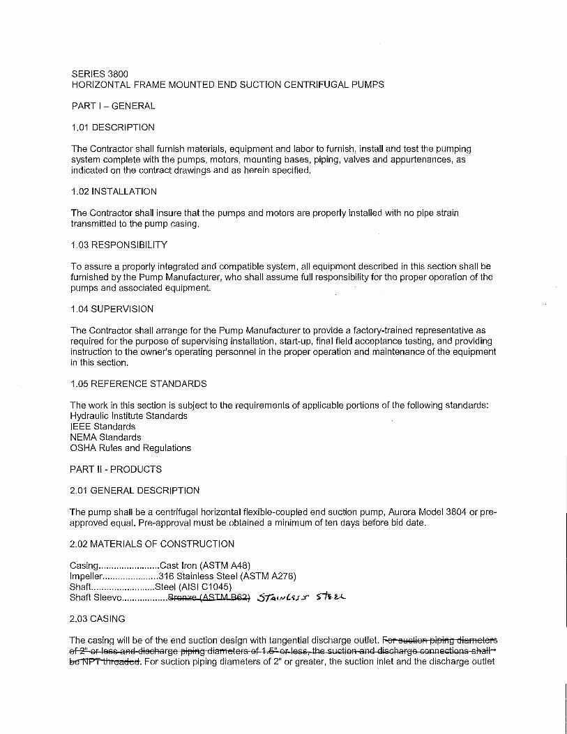
SERIES 3800 HORIZONTAL FRAME MOUNTED END SUCTION CENTRIFUGAL PUMPS
PART I - GENERAL
1.01 DESCRIPTION
The Contractor shall furnish materials, equipment and labor to furnish, install and test the pumping system complete with the pumps, motors, mounting bases, piping, valves and appurtenances, as indicated on the contract drawings and as herein specified.
1.02 INSTALLATION
The Contractor shall insure that the pumps and motors are properly installed with no pipe strain transmitted to the pump casing.
1.03 RESPONSIBILITY
To assure a properly integrated and compatible system, all equipment described in this section shall be furnished by the Pump Manufacturer, who shall assume full responsibility for the proper operation of the pumps and associated equipment.
1.04 SUPERVISION
The Contractor shall arrange for the Pump Manufacturer to provide a factory-trained representative as required for the purpose of supervising installation, start-up, final field acceptance testing, and providing instruction to the owner's operating personnel in the proper operation and maintenance of the equipment in this section.
1.05 REFERENCE ST AN DAROS
The work in this section is subject to the requirements of applicable portions of the following standards: Hydraulic Institute Standards IEEE Standards NEMA Standards OSHA Rules and Regulations
PART II - PRODUCTS
2.01 GENERAL DESCRIPTION
The pump shall be a centrifugal horizontal flexible-coupled end suction pump, Aurora Model 3804 or preapproved equal. Pre-approval must be obtained a minimum of ten days before bid date.
2.02 MATERIALS OF CONSTRUCTION
Casing ........................ Cast Iron (ASTM A48) lmpeller ...................... 316 Stainless Steel (ASTM A276) Shaft.. ....................... Steel (AISI C1045) Shaft Sleeve ................. .13rgn~e 'ASTM Se~~ .S/A1tJl'iJ ..:r S~~
2.03 CASING
The casing will be of the end suction design with tangential discharge outlet. Fer Sl:lGtion pipil'I~ diameters ef-2" or less aAf:l cltseharge pipiR~ dia11leters of 1.5" or less, the s11ction and dis~ BtrMF''f ti 11 eaded. For suction piping diameters of 2" or greater, the suction inlet and the discharge outlet

shall be a bolt through flange connection, and tapped for pressure gages. Flange connections shall be ANSI 125# rated. The casing shall have tapped and plugged holes for priming and draining. The casing bore shall be large enough to allow "back pullout" of the impeller without disturbing the casing or suction and discharge piping. The casing shall have integral cast feet.
2.04 IMPELLER
The impeller shall be of the enclosed type, and investment cast. It shall be finished all over, the exterior being turned and the interior being finished smooth and cleaned of all burrs, trimmings, and irregularities. The impeller shall be dynamically balanced. The impeller will be keyed to the shaft, and fastened with a washer, gasket and capscrew.
2.05 MOTOR BRACKET AND SEAL PLATE
The seal plate and motor bracket shall be of a two piece design, and shall provide an adequate area for internal recirculation of the pumped fluid around the sealing medium.
2.06 MECHANICAL SEAL
Shaft sealing shall be accomplished by means of a mechanical seal with a Ceramic seat, carbon washer, Buna-N elastomers, and stainless steel metal parts.
2.07 SHAFT
The impeller shall be direct-coupled to the motor shaft. The motor shaft shall be machined to provide a keyway, and drilled and tapped to accept the impeller fastener. Stub shafts are not acceptable. The outboard shaft extension shall be machined with a keyway to accept a coupling to the driving unit. Lip seals shall be furnished on both the inboard and outboard shaft extensions, and a water slinger shall be furnished on the inboard shaft extension closest to the mechanical seal.
2.08 SHAFT SLEEVE
The pump shaft shall be fitted with a shaft sleeve to minimize shaft wear. The sleeve shall be sealed to the impeller hub by an 0-ring, and shall be positively driven by a pin to the keyway. The use of adhesive compounds to fasten the sleeve to the shaft shall not be accepted.
2.09 POWER FRAME
The power frame shall house a single-row outboard regreaseable thrust bearing. Both bearings shall be selected for a 3 year minimum life at maximum load. The outboard bearing shall be locked in place by a retaining ring. The inboard bearing shall not be locked in order to accommodate thermal expansion of the shaft. Lubrication fittings shall be provided in convenient location. A bearing cartridge end cap shall be provided on the outboard side of the power frame to allow inspection of the thrust bearing without the need for disassembling the power frame housing.
2.10 FOOT SUPPORTS
The pump unit shall be supported from feet cast into the casing and a bracket mounted to the power frame.
2.11 BASEPLATE
The pump and motor shall be mounted on a groutable formed steel baseplate or a drip-rim baseplate with integral drip channels incorporated on each side. Each channel shall include an NPT drain connection and plug. The base shall be sufficiently rigid to support the pump and the motor without the use of additional supports or members.
2.12 COUPLING
A flexible coupling shall be provided to connect the pump shaft to the motor shaft. The coupling shall be of an all metal type with a flexible rubber insert. The entire rotating coupling assembly shall be enclosed by a coupling guard.
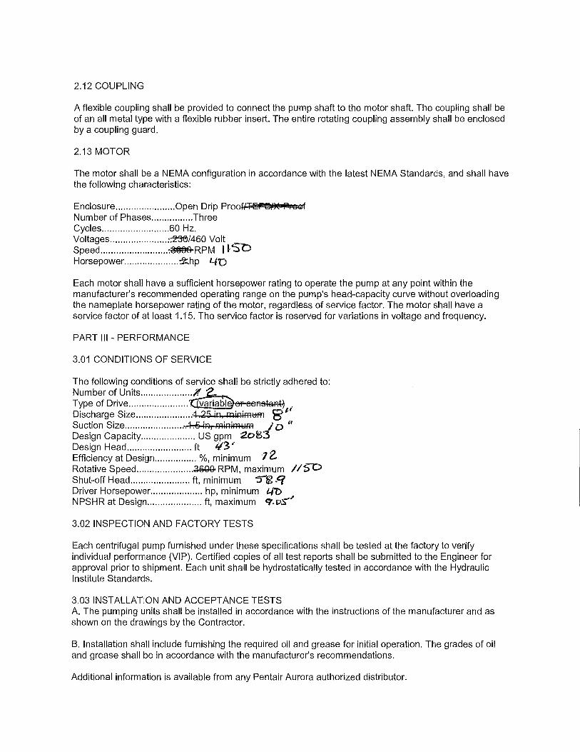
2.13 MOTOR
The motor shall be a NEMA configuration in accordance with the latest NEMA Standards, and shall have the following characteristics:
Enclosure ....................... Open Drip ProolfFEF@l/)( P, GG1f Number of Phases ................ Three Cycles .......................... 60 Hz. Voltages .................. .... :~1460 Volt Speed .......................... ~RPM I VSO Horsepower ..................... ~hp 40
Each motor shall have a sufficient horsepower rating to operate the pump at any point within the manufacturer's recommended operating range on the pump's head-capacity curve without overloading the nameplate horsepower rating of the motor, regardless of service factor. The motor shall have a service factor of at least 1.15. The service factor is reserved for variations in voltage and frequency.
PART Ill - PERFORMANCE
3.01 CONDITIONS OF SERVICE
The following conditions of service shall be strictly adhered to: Number of Units .................. ~ Type of Drive ....................... ~or eol'lstant~ Discharge Size ..................... :1 25 in, miniFAUA1 8"( S t. s· ~ §. .. ,, uc ion 1ze........................ . 1n, m11:i1m1,1ff! / o Design Capacity ..................... US gpm 2o$3 Design Head ......................... ft '13"'
0 Eff. . t D . o1 • • 'l t:.-1c1e ncy a es1gn ................ 10, minimum Rotative Speed ...................... ~RPM, maximum //S-0 Shut-off Head ....................... ft, minimum 5'g ~Cf Driver Horsepower .................... hp, minimum /../() NPSHR at Design ..................... ft, maximum C"(.DS''
3.02 INSPECTION AND FACTORY TESTS
Each centrifugal pump furnished under these specifications shall be tested at the factory to verify individual performance (VIP). Certified copies of all test reports shall be submitted to the Engineer for approval prior to shipment. Each unit shall be hydrostatically tested in accordance with the Hydraulic Institute Standards.
3.03 INSTALLATION AND ACCEPTANCE TESTS A. The pumping units shall be installed in accordance with the instructions of the manufacturer and as shown on the drawings by the Contractor.
B. Installation shall include furnishing the required oil and grease for initial operation. The grades of oil and grease shall be in accordance with the manufacturer's recommendations.
Additional information is available from any Pentair Aurora authorized distributor.

.PENTAIR
AURORA®
Model 3804
MODELS 3801 AND 3804 END SUCTION PUMPS INSTRUCTION, INSTALLATION, MAINTENANCE
AND REPAIR MANUAL NOTE! To the installer: Please make sure you provide this manual to the owner of the equipment or to the responsible party who maintains the system.
Part# A-03-327 I © 2014 Pentair Ltd. I 02/17/14

SECTION 6 ITEM 3800 DATED FEBRUARY 2014 SUPERSEDES NOVEMBER 2012
IMPORTANT NOTE TO INSTAI.LER:
This manual contains important information about the installation, operation and safe use of this product. This information should be given to the owner/operator of this equipment.
APPIJCATIONS:
The 3800 Series pumps are frame mounted or close coupled. They feature high efficiency, rngged constrnction, foot mounted volutes with back pullout power frames, center drop out spacer coupling (optional) and regreaseable ball bearings. The pump's stainless steel fitted construction is suitable for unheated domestic and fresh water, condensate, boiler feed water, pressure boosting and hydronic coiling and/or heating.
ATTENTION: SAFETY WARNINGS:
Read and understand all warnings before installation or servicing pump.
OPERATIONAL LIMITS: * Maximum Operating Pressure:
Maximum Operating Temperature:
175 psi at Temperatures to 150°F (65.6°C) 225°F (107°C)
*See ASTM A126/ANSI Bl6.1 for pressure/temperature ratings of flanges.
ELECTRICAL SAFETY:
Aw arning: Electrical Shock Hazard
All electrical connections are to be made by a qualified electtician in accordance with all codes and ordinances. Failure to follow these instructions could result in serious personal injury, death or property damage.
Aw arning: Electrical Overload Hazard
Ensure all motors have properly sized overload protection. Failure to follow these instructions could result in serious personal injury, death or prope1ty damage.
A Warning: Sudden Start-Up Hazard
Disconnect and lock out power source before servicing. Failure to follow these instructions could result in serious personal injury, death or property damage.
• PENTAIR AURORA' 2
A Warning: Hot Surface Hazard
If pumping hot water, ensure guards or proper insulation is installed to protect against skin contact with hot piping or pump components. Failure to follow these instrnctions could result in serious personal injury, death or propetty damage.
A Warning: Spraying Water Hazard
When servicing pump replace all gaskets and seals. Do not reuse old gaskets or seals. Failure to follow these instrnctions could result in serious personal injury, death or property damage.
A Warning: High Pressure Hazard
The pump is rated at a maximum of 175 psi at 150°F. Do not exceed this pressure. Install properly sized pressure relief valves in system. Failure to follow these instructions could result in serious personal injury, death or property damage.
A Warning: Expansion Hazard
Water expands when heated. Install properly sized themrnl expansion tanks and relief valves. Failure to follow these instructions could result in serious personal injury, death or property damage.
HIGH TEMPERATURE SAFETY:
HIGH PRESSURE SAFETY: INSTALJ,ATJON
Read and understand all safety warnings at the beginning of the manual before beginning installation or any repair work.
PUMP LOCATION. You probably have spent considerable time planning where your pump will be located. However, you may have overlooked some factor that may affect pump operation or efficiency.
The pump should be located as close to the· liquid source as possible so that the suction line can be short and direct. It should be located in a clean, open area, where it is easily accessible for inspection, disassembly and repair. Pumps
A Warning: California proposition 65 warning
This product and related accessories contain chemicals known to the State of California to cause cancer, birth defects or other reproductive harm .

installed in dark, dirty areas or in cramped locations are often neglected, which can result in premature failure of both the pump and the driver.
The Aurora® pump must be installed horizontally. Install isolating valves on each side of pump so pump maintenance can be performed without draining the system. Special mounting requirements may be required if the pump is to be mounted near a noise or vibration sensitive area.
The installation l1ll!fil be evaluated to ensure that the net positive suction head available (NPSHA) meets or exceeds the net positive suction head required (NPSHR), as stated by the pump performance curve.
FOUNDATION. The foundation for your pump must be sufficiently rigid to absorb any vibration and stress encountered during pump operation. A raised foundation of concrete is preferable for most floor mounted pumps. The raised foundation assures a satisfactory base, protects against flooding, simplifies moisture drainage, and facilitates keeping the area clean.
Your pump should be firmly bolted to the foundation, whether it is a raised concrete base, steelwork wall, or structural member. The mounting bolts or lag screws should be accurately located per the applicable Aurora dimension sheet. Refer to Fig. I.
LEVELING THE PUMP. Leveling the pump will require enough shims to support the base plate near the foundation bolts and at any points of the base plate canying a substantial weight load. The shims should be large enough to allow a gap of 3/4" to 1-1/2" between the base plate and foundation for grouting.
IMPORTANT: The pump base must be set level to avoid any mechanical difficulties with the pump or motor. The 3800 pump was properly aligned, if supplied with a motor, at the factory. However, since the pump base is flexible, it may spring and twist during shipment. Do not pipe the pump until it is realigned. Realign the base after piping is completed and after the pump is grouted in and bolted down. NOTE: It may be necessary to readjust the alignment from time to time while the unit and foundation are new. Realignment will prevent premature bearing failure, excessive vibration or shaft failure.
Ensure that proper hydronic accessories such as pressure relief valves, thermal expansion tanks and flow/pressure control devices are installed in the system. Consult the responsible party for your system to ensure these devices are installed and of the proper size.
STRAIGHT EDGE
WEDGE OR THICKNESS GAUGE --~
SECTION 6 ITEM 3800 DATED FEBRUARY 2014
SUPERSEDES NOVEMBER 2012
,.D-RIV-ER~--FLE,....XIBO CUNG
0
PUMP
FOUNDATION BOLT SHIMS SHIMS
GROUTING CLEARANCE
Figure 1. Foundation for Frame Mounted Pumps.
Figure 2. Grouting the Base for Frame Mounted Pumps.
GROUTING THE INSTALLATION. Grouting the base plate prevents lateral movement of the base plate, and improves the vibration absorbing characteristics of the foundation by increasing its mass. A wooden dam should be constructed around the base plate to contain the grout while it is being poured. The dam can be built tight against the base plate, or slightly removed from it as desired. Refer to Fig. 2. The entire base plate should be completely filled with non-shrinkable type grout. The grout should be puddled frequently to remove any air bubbles from the grout.
ROTATION. Pump rotation is clockwise when viewed from the back of the motor. An anow is also located on the pump to show the direction ofrotation.
PARALLEL MISALIGNMENT ANGULAR MISALIGNMENT PERFECT ALIGNMENT
Figure 3. Flexible Coupling Alignment.
3 .PENTAIR AURORA.
SECTION 6 ITEM 3800 DATED FEBRUARY 2014 SUPERSEDES NOVEMBER 2012
A Warning: Sudden Start-Up Hazard
Disconnect and lock out power source before servicing. Failure to follow these instructions could result in serious personal injury, death or property damage.
INITIAL ALIGNMENT OF THE FLEXIBLE COUPLING. The pump and driver were accurately aligned at the factory. However, it is impossible to maintain this alignment during shipping and handling. Therefore it will be necessary for you to realign the pump and driver. Flexible couplings are not universal joints. They should not be used to compensate for misalignment of the pump and motor shafts. Their function is to transmit power from the driver to the pump while compensating for them1al expansion and shaft end movement. The coupling faces should be far enough apart so that they do not make contact when the motor shaft is forced to the limit of the bearing clearance toward the pump shaft.
In order to properly align the coupling, you will need a taper gauge or set of feeler gauges, and a straight edge.
There are two types of misalignment encountered with flexible couplings: angular misalignment, in which the shafts are not parallel, and parallel misalignment where the shafts are parallel but not on the same axis.
To check angular alignment, insert a feeler gauge or taper gauge at any four places 90° apart around the coupling halves. Insert shims under the driver feet until the same reading is obtained at all four check points. The pump and driver will then be in angular alignment.
To check parallel alignment, a straight edge should be held against the edges of the coupling halves at any four places 90° apart around the coupling. The su·aight edge should be parallel to the pump and driver shafts at all times. Insert shims until the straight edge lies flat against both coupling halves at all four checkpoints. The pump and driver will then be in proper parallel alignment. Refer to Fig. 3.
For fine alignment, 3500 RPM operation, for all other coupler types.
A dial indicator should be used when greater alignment accuracy is required. Use the following alignment tolerances unless specified otherwise by the coupling manufacturer. On
Figure 4. Installation of Tapered Reducers.
.PENTAIR AURORA.
ELBOW
AIR POCKET
4
Figure 5. Gate Valve and Check Valve.
sleeve type couplings make sure there is at least 1/8" end clearance between the sleeve and the two coupling halves.
To check angular misalignments, mount the dial indicator base to the coupling half, and position the dial indicator button on the front or rear face of the opposite coupling half. Set the dial to zero, rotate both coupling halves together, making sure the indicator button always indicates off the same spot. Misalignment values within 0.004 inches TIR per inch of coupler radius is pennissible.
To check parallel misalignment, mount the dial indicator base to one coupling half, or shaft and position the dial indicator button on the outside diameter of the opposite coupling half. Set the dial to zero. Rotate both coupling halves together, making sure the indicator button always indicates off the same spot. Misalignment within 0.004 inches TIR is pennissible.
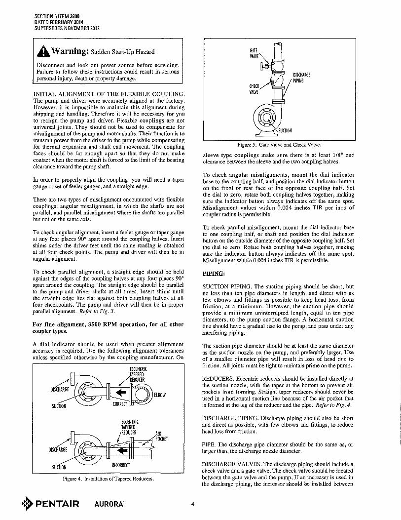
PIPING:
SUCTION PIPING. The suction piping should be short, but no less than ten pipe diameters in length, and direct with as few elbows and fittings as possible to keep head loss, from friction, at a minimum. However, the suction pipe should provide a minimum uninterrupted length, equal to ten pipe diameters, to the pump suction flange. A horizontal suction line should have a gradual rise to the pump, and pass under any interfering piping.
The suction pipe diameter should be at least the same diameter as the suction nozzle on the pump, and preferably larger. Use of a smaller diameter pipe will result in loss of head due to friction. All joints must be tight to maintain prime on the pump.
REDUCERS. Eccenu·ic reducers should be installed directly at the suction nozzle, with the taper at the bottom to prevent air pockets from fom1ing. Straight taper reducers should never be used in a horizontal suction line because of the air pocket that is formed at the leg of the reducer and the pipe. Refer to Fig. 4.
DISCHARGE PIPING. Discharge piping should also be short and direct as possible, with few elbows and fittings, to reduce head loss from friction.
PIPE. The discharge pipe diameter should be the same as, or larger than, the discharge nozzle diameter.
DISCHARGE VALVES. The discharge piping should include a check valve and a gate valve. The check valve should be located between the gate valve and the pump. If an increaser is used in the discharge piping, the increaser should be installed between

the pump nozzle and the check valve. The check valve protects against a reverse flow of the liquid if the driver fails. Refer to Fig. 5.
The gate valve is used in the priming operation, as a throttling valve to control pump volume, and to shut down the pump for inspection and maintenance.
LUBRICATION:
In dry locations, each bearing will need lubrication at least after every 4,000 hours of running time or 6 to 12 months, whichever is more frequent. In wet locations (exposed to dripping water, to the weather or to heavy condensation found in unheated or poorly ventilated underground locations) every 2,000 hours or eve1y 3 to 6 months, whichever is more frequent.
Use Chevron SRI, NLGI2.
Lubricate motor per motor manufacturer's instructions.
GENERAL INSTRUCTIONS: 1. Keep this pump and motor properly lubricated. 2. When there is a danger of freezing, drain the pump. 3. Inspect the pump regularly for leaky seals of gaskets
and loose or damaged components. Replace or repair as required.
ELECTRICAL WIRING. Normally, your pump will be supplied with an attached drive motor. The motor should be wired in accordance with the wiring diagram found on the motor nameplate. Be sure the voltage, frequency, and phase of your power supply corresponds with the nameplate data. It is advisable to provide a separate switch and overload protection for your pump motor to protect against power failure in some other area. Conversely, if the pump motor develops electrical problems, it will be isolated from other equipment.
PRESTARTING INSTRUCTION. The coupling halves should be connected. Prior to connection, however, the drive motor should be started to make sure the direction of rotation is the same as the direction indicated by the arrow on the pump casing.
PUMP DISASSEMBLY: For frame mounted pumps, model 3804.
A Warning: Sudden Start-Up Hazard
Disconnect and lock out power source before servicing. Failure to follow these instructions could result in serious personal injury, death or property damage.
Read and understand all safety warnings at the beginning of the manual before beginning installation or any repair work.
1. Ensure the electrical power is locked out, the system pressure has been lowered to 0 psi and temperature of the unit is at a safe level before beginning any disassembly of the pump.
2.Isolate the pump from the system by closing the valves that should be located on both the suction and discharge of the pump. Loosen the drain plug at the bottom of the casing and drain the pump.
Inspect removed parts at disassembly to determine if they can be reused. Ball bearings that tum roughly or show wear should
5
SECTION 6 ITEM 3800 DATED FEBRUARY 2014
SUPERSEDES NOVEMBER 2012
be replaced. Cracked castings should never be reused. Scored or worn pump shafts should be replaced. Gaskets should be replaced at reassembly simply as a matter of economy. They are much less expensive to replace routinely than to replace singly as the need arises.
A Warning: Hot Surface Hazard
If pumping hot water, ensure guards or proper insulation is installed to protect against skin contact with hot piping or pump components. Failure to follow these instructions could result in serious personal injury, death or property damage.
Aw arning: High Pressure Hazard
The pump is rated at a maximum of 175 psi at 150°F. Do not exceed this pressure. Install properly sized pressure relief valves in system. Failure to follow these insttuctions could result in serious personal injury, death or property damage.
A Warning: Spraying Water Hazard
When servicing pump replace all gaskets and seals. Do not reuse old gaskets or seals. Failure to follow these instructions could result in serious personal injury, death or property damage.
3. For 3804 pumps, remove the coupling guard.
4. For 3804 pumps, loosen the set screws in both coupling halves and slide each half back as far as possible on its shaft. Then, remove the coupling sleeve.
Aw arning: High Pressure Hazard
Make certain that the internal pressure of the pump is relieved before continuing. Failure to follow the instructions could result in serious person injury, death, or property damage.
5. Remove the two foot suppott capscrews. Loosen, but do not remove the volute capscrews (5). Use capscrew in the jack screw holes to loosen the pump assembly from the volute.
6. Now remove the volute capscrews (5) and remove the pump assembly from the volute.
7. Remove the impeller capscrew (9), lockwasher (9A) and impeller washer gasket (9B). Remove impeller (11).
8. Remove impeller key (12).
9. Remove the 0-ring (10).
10. Remove the rotating portion of the mechanical seal (head). Refer to Fig. 6.
11. Remove the stationary portion of seal insert along with the insert gasket and retainer (if used) .
• PENTAIR AURORA'

SECTION 6 ITEM 3800 DATED FEBRUARY 2014 SUPERSEDES NOVEMBER 2012
CAPSCREW TORQUE FOR COMMON BOLT DIAMETERS CAPSCREW HEAD IN-POUNDS FOOT ·POUNDS
TYPE MARKING 1/4" I 5/16" 3/8" I 1 /16" I 1/2" I 5/8" I 3/4" SAE Grade 5 G7 85 I 180 27 I 43 I 65 I 130 I 230
Table l. Torque Chart
Figure 6. Mechanical Seal.
PUMP REASSEMBLE:
1. Thoroughly clean the shaft sleeve and seal plate seal cavity. Replace the shaft sleeve (25) or seal plate (35A) if there is evidence of surface damage like pitting, corrosion, nicks or scratches.
2. Lubricate the shaft sleeve and seal plate with soap and water or P-80 rubber emulsion. Do not use petroleum lubricant. Install a new insert gasket and a new seal insert down into the seal plate.
3. Slide a new rotating seal assembly (27) on to the shaft sleeve. With a screwdriver, push the top of the compression ring until the seal is tight against the seal insert. Install seal spring.
CAUTION
The mechanical seal (see Figure 6) (27) is a precision product and must be treated as such. During installation, great care must be taken to avoid dropping any pat1 of the seal. Take particular care not to scratch the lapped faces on the washer or the sealing seat.
4. Install 0-ring (10).
5. Install a new impeller key (12).
6. Install impeller, impeller washer (9A), new impeller washer gasket (9B), lock washer (9C), and capscrew (9). Tighten capscrew per torque chart (see Table 1).
7. Install new casing gasket (8). Then install the pump assembly into the volute.
8. Tighten volute capscrews (5) per torque chart (see Table 1).
9. For 3804 pumps, install foot support capscrews (62) and tighten per torque chart (see Table 1).
10. For 3804 pumps, install coupling and align.
+PENTAIR AURORA. 6
11. Install drain plugs, close drain valve.
12. For 3804 pumps, reinstall the coupling guard.
A Warning: Sudden Start-Up Hazard
Disconnect and lock out power source before servicing. Failure to follow these instructions could result in serious personal injury, death or property damage.
13. Open isolation valves and inspect pump for leaks.
14. Return pump to service.
POWER FRAME OR PUMP SHAFT DISASSEMBLY/REPLACEMENT:
Read and understand all safety warnings at the beginning of the manual before beginning installation or any repair work.
Follow steps 1-11 from main pump disassembly procedure.
12.Remove the Seal Plate (35A) capscrews (5B) from the bracket (35B).
13.Remove the power frame capscrews (5) and washers (5A) from the bracket (35B). If the power frame assembly is being replaced, skip to reassembly step 5 after replacement. If replacing the shaft (55), continue to step 14.
14. Remove the grease fittings (43) from the power frame.
15. Unscrew capscrews (48) and remove bearing cap (49). Remove 0-ring (oil lubed only) and retainer ring (52).
16. Slide out shaft (55) and beatings (53 and 54). Since bearings (53 and 54) ai·e press fitted on the shaft, they will have to be pulled or pressed off the shaft. Remove grease seals (51) from frame (57) and bearing cap (49).
17. Thoroughly clean the shaft (55), removing any oil or dirt.
POWER FRAME REASSEMBLE:
Reassembly will generally be in reverse order of disassembly. If disassembly was not complete, use only those steps related to your patticular repair program.
1. Press grease seals (51/51A) into frame (57) and bearing cap (49).
2. Press bearings (53 and 54) onto shaft (55). Snap retainer ring (52) into place.
3. Slide shaft (55) and beat-ings (53 and 54) into frame (57).
4.Fasten bearing cap (49) in position with capscrews (48). Position slingers (47) on the shaft.

5. Position the bracket (35B) on the frame (57) and secure with capscrews (5) and washers (5A). Tighten screws evenly to assure proper alignment.
6. Position the Seal Plate (35A) on the bracket (35B) and secure with capscrews (5B). Tighten screws evenly to assure proper alignment.
Follow steps 1 through 14 from Pump Reassemble procedure to complete pump assembly.
Do not start pump until all air and vapor has been bled and until making sure that there is liquid in the pump to provide the necessary lubrication for the packing.
Figure 7. Model 380 I.
7
SECTION 6 ITEM 3800 DATED FEBRUARY 2014
SUPERSEDES NOVEMBER 2012
AURORA® RESERVES THE RIGHT TO SUBSTITUTE MATERIALS WITHOUT NOTICE.
NOTE: WHEN ORDERING SPARE PARTS ALWAYS INCLUDE THE PUMP TYPE, SIZE, SERIAL NUMBER, AND THE PIECE NUMBER FROM THE EXPLODED VIEW IN THIS MANUAL. ORDER ALL PARTS FROM YOUR LOCAL AUTHORIZED DISTRIBUTOR OR THE FACTORY AT NORTH AURORA, ILLINOIS.
MODELS 3801 & 3804 LIST OF PARTS
4. Pipe Plug
4A/B. Capscrew
SA. Capscrew Washer
5B. Capscrew
6. Casing
8. Gasket
9. Impeller Screw
9A. Washer
9B. Gasket
9C. Capscrew Seal
10. 0-ring
II. Impeller
12. Impeller Key
25. Sleeve
27. Seal
32. Capscrew
33. Screw
34. Nameplate
35A. Seal Plate
35B. Motor Bracket
42. Key
43. Grease Fitting
47. Slinger
48. Capscrew
49. Bearing Cap
52. Retaining Ring
53. Bearing
54. Bearing
55. Shaft
57. Fran1e
62A. Capscrew
62B. Nut
63. Washer
64AIB • Foot Support
• PENTAIR AURORA'
(952) 831-4340 • 800-831-7914 • (952) 831-2357 fax 5250 West 74th Street, Minneapolis, MN 55439
SALES Aurora
Fairbanks Morse
Hydromatic
LayneNerti-Line
Goulds Vertical Turbine
Grundfos
(218) 829-6890 • (218) 829-6972 fax 7674 College Road, Ste. 105, Baxter, MN 56425
SERVICE All Makes and Models of Pumps, motors and controls
Motor rewinding
Surge testing
Fully equipped service centers
Fully equipped service trucks
Preventive maintenance contracts
800-831-7914