re-designing the current regenerative hydraulic braking ... · the objective of this term’s...
TRANSCRIPT

Re-designing the Current Regenerative Hydraulic Braking System in a Bike for Wheelchair Application
Michael Kezelian, Heather Li, Alekhya Ratnala, Hai Wang Sponsor: David Swain, Environmental Protection Agency
ME450, Design and Manufacturing III
Department of Mechanical Engineering University of Michigan
Ann Arbor, MI 48109-2125
SECTION 006, Team 24
Tuesday, April 20th, 2010
ABSTRACT The U.S. Environmental Protection Agency (EPA) is researching hydraulic hybrid transportation systems
in an effort to diminish the pollutants released from emissions and reduce the demand for fossil fuels. One
method of achieving this is to use hydraulic regenerative braking systems to store energy in pressurized
fluids. This stored energy can then be released to assist in vehicle acceleration. For several years, the EPA
has teamed with University of Michigan students to develop designs for the hydraulic regenerative
braking system to be utilized in bicycles. The objective of this term’s project is to refine previous
generations of the hydraulic system in a bicycle while re-designing the system for it to be applicable for
wheelchairs.
EXECUTIVE SUMMARY The task the U.S. Environmental Protection Agency (EPA) has defined is to prototype a refined hydraulic
regenerative braking system (HRBS) in the front wheel of a children’s bike while making design changes
to allow the system to be applicable for wheelchairs. Due to the increase in interest for energy efficient
methods, the EPA has been researching alternative forms of energy for automobiles, such as the HRBS.
This system is designed to conserve energy that is normally lost during frictional braking. The kinetic
energy of the vehicle is used to power a pump that pushes hydraulic fluid from a low-pressure reservoir to
a high-pressure accumulator, bringing the vehicle to a stop. This stored energy may then be released to
propel the vehicle forward, providing acceleration without manual force. The EPA has already
implemented this type of system in larger vehicles such as UPS delivery trucks, and has decided to apply
the system in smaller scale applications. In collaboration with the EPA, University of Michigan students
have previously produced a HRBS contained in the front wheel of a bicycle. Unfortunately, previous
prototypes of the HRBS in the front wheel of a children’s bicycle have been unsuccessful in functioning
properly.
Thus, the objective for this term is to optimize previous designs of the HRBS by addressing the failures of
previous systems. While improving the system, re-designs will also be made to the HRBS to allow the
system to be implemented in a wheelchair’s wheel. Creating an HRBS that can be applied to a wheelchair

2
will allow wheelchair users to control their speed on hill decent and apply an assist during hill climbing.
In order to achieve these objectives, significant tasks include manufacturing a functioning prototype that
has a more lightweight and rigid system compared to previous generations and allowing the system to
measure pressure through the axle. Similar to previous terms, the HRBS will be enclosed in a 20‖ bicycle
wheel with minimal changes to the hydraulic system, as the components have been well researched,
documented, and tested by Mr. David Swain and previous teams.
Challenges in creating a functional HRBS include the ability to package the system in such a small space,
keeping the weight of the overall system at a minimum and ensuring that the system does not interfere
with the true spin of the wheel. A list of customer requirements was discussed with Mr. David Swain to
address these concerns. The most important customer requirements for this project include being able to
measure pressure through the axle, making the superbracket (the metal plate on which all the components
are mounted on) more durable, and keeping the weight of the system at a minimum. The most significant
engineering specifications related to these customer requirements are measuring the energy capacity of
the system, determining the maximum stress applied to the superbracket, and the weight of the system.
The target values for the maximum stress on the superbracket and energy capacity of the system cannot
be calculated until start of the initial design stage and therefore have not been determined for this report.
The goal for the weight of the system is 20 lbs or less.
Benchmarking was conducted to determine further specifications and once these products were evaluated,
engineering specifications were determined. To correlate and compare these customer requirements,
benchmarks and engineering requirements, a Quality Function Development was conducted.
Based on recommendations provided by David Swain and experiences of previous teams that have
worked with the HRBS, it was suggested to begin sourcing and ordering materials that have generally had
long acquisition lead times. Thus, ordering of the parts has already begun and disassembly of the previous
prototypes to cultivate further designs will be performed before the second design review on February
18th, 2010. A final design selection and the plan for prototype production will be done by the third
design review on March 18th
, 2010. Manufacturing and assembly of our system will be accomplished by
the fourth design review, after which testing of the prototype will begin immediately. Fixes or additional
adjustments to the system will be made and refined by the design expo on April 15th, 2010.

TABLE OF CONTENTS INTRODUCTION ....................................................................................................................................... 3
Background Information ........................................................................................................................ 3
Motivations. ......................................................................................................................................... 3
Comparison to Other Hybrid Systems. ............................................................................................. 4
Previous Work . .................................................................................................................................. 5
Understanding How the Current System Works. ............................................................................ 5
CUSTOMER AND ENGINEERING SPECIFICATIONS ..................................................................... 6
Customer Requirements ......................................................................................................................... 6
Engineering Specifications ..................................................................................................................... 8
Benchmarking ......................................................................................................................................... 8
Quality Function Development .............................................................................................................. 8
PROBLEM ANALYSIS ............................................................................................................................. 9
CONCEPT GENERATION ..................................................................................................................... 10
Function 1: Being Able to Measure the Pressure through the Axle ................................................. 13
Concept 1: bore extra path through solenoid housing to allow cross-flow. ................................ 13
Concept 2: direct flow from separate housing ................................................................................ 13
Concept 3: add piping from outside of solenoid housing ............................................................... 13
Concept 4: external hose through the axle. ..................................................................................... 13
Function 2: Increasing the Stiffness of the Superbracket ................................................................. 13
Concept 1: change geometry and thickness of the superbracket .................................................. 14
Concept 2: cut slots in superbracket and bend the metal outward .............................................. 14
Concept 3: add metal bars to the areas of high stress ................................................................... 14
Concept 4: add extra material to the areas of high stress ............................................................. 14
Function 3: Method of Releasing Energy ........................................................................................... 14
Concept 1: two press buttons on each handle of the bicycle. ........................................................ 14
Concept 2: a toggle switch with a cap. ............................................................................................ 15
Concept 3: one press button on the handle of the bicycle.............................................................. 15
Concept 4: a dial switch .................................................................................................................... 15
Function 4: Preventing Leakage of the Hydraulic Fluid ................................................................... 15
Concept 1: piping thread sealant TS500’s. ..................................................................................... 15
Concept 2: JIC fittings . ................................................................................................................... 15
Concept 3: O-ring fittings................................................................................................................. 15
CONCEPT EVALUATION ..................................................................................................................... 16
Evaluation of Advantages and Disadvantages .................................................................................... 16
Function 1: allowing pressure to flow through the axle . ............................................................. 16
Function 2: increasing durability of the superbracket .................................................................. 17
Function 3: method of energy release for the user . ...................................................................... 18
Function 4: preventing leakage of the hydraulic system. .............................................................. 18
Systematic Evaluation .......................................................................................................................... 19
CONCEPT SELECTION ......................................................................................................................... 21
Function 1: Measuring the Pressure through the Axle...................................................................... 21
Function 2: Increasing the Stiffness of the Superbracket ................................................................. 21
Function 3: Method of Energy Release ............................................................................................... 22
Function 4: Preventing Leakage of the Hydraulic System ................................................................ 23
ENGINEERING DESIGN PARAMETER ANALYSIS........................................................................ 23
System Modeling ................................................................................................................................... 23
Motor and Pump Performance Curves ............................................................................................... 25
Gear Reductions .................................................................................................................................... 27
Transmission tuning analysis ......................................................................................................... 28

Pump and motor system losses ...................................................................................................... 28
Bike System............................................................................................................................................ 28
Bike system losses ............................................................................................................................ 29
Hydraulic System .................................................................................................................................. 29
Hydraulic system losses. ................................................................................................................... 30
Customer Requirement Calculations .................................................................................................. 30
Superbracket Stiffness Analysis .......................................................................................................... 31
FINAL DESIGN DESCRIPTION ........................................................................................................... 32
Hydraulic System .................................................................................................................................. 34
Braking............................................................................................................................................... 34
Accelerating ....................................................................................................................................... 34
Check valve . ..................................................................................................................................... 35
Filter . ................................................................................................................................................ 35
Relief valve . ...................................................................................................................................... 35
Fittings and tubing. ........................................................................................................................... 35
High-pressure accumulator . ........................................................................................................... 35
Motor and pump. .............................................................................................................................. 35
Powertrain ............................................................................................................................................. 35
Superbracket ......................................................................................................................................... 37
Solenoid Housing. .................................................................................................................................. 37
Axle. ........................................................................................................................................................ 38
User Interface and Controls ................................................................................................................. 39
PROTOTYPE DESCRIPTION ............................................................................................................... 40
FABRICATION PLAN ............................................................................................................................ 40
Hydraulics .............................................................................................................................................. 41
Powertrain ............................................................................................................................................. 41
Superbracket ......................................................................................................................................... 42
Fork ........................................................................................................................................................ 42
User Interface & Controls .................................................................................................................... 42
Spokes .................................................................................................................................................... 43
Assembly ................................................................................................................................................ 43
VALIDATION PLAN ............................................................................................................................... 43
Initial Validation Test Plan .................................................................................................................. 43
Physical Validation Test Plan .............................................................................................................. 44
Safety for Validation Testing ............................................................................................................... 44
Validation Testing Outcome ................................................................................................................ 44
PROJECT PLAN ...................................................................................................................................... 46
Phase I: Initial Research ...................................................................................................................... 46
Phase II: Initial Designs ........................................................................................................................ 47
Phase III: Design Selection ................................................................................................................... 47
Phase IV: Prototype Production .......................................................................................................... 47
Phase V: Prototype Testing and Project Completion ........................................................................ 47
DISCUSSION ............................................................................................................................................ 47
Machining and Manufacturing ............................................................................................................ 47
Assembly ................................................................................................................................................ 48
Working with Outside Sources ............................................................................................................ 48
Please read the Validation Outcome section on page 45. ....................................................................... 48
RECOMMENDATIONS .......................................................................................................................... 48
CAD Modeling ....................................................................................................................................... 48
Pump/Motor .......................................................................................................................................... 48
Working with Professionals ................................................................................................................. 49

Avoiding Pipe Threading ..................................................................................................................... 49
Scheduling .............................................................................................................................................. 49
Out-of-Hub Possibilities ....................................................................................................................... 49
Another Possibility ................................................................................................................................ 50
CONCLUSIONS ....................................................................................................................................... 50
ACKNOWLEDGEMENTS. .................................................................................................................... 51
REFERENCES .......................................................................................................................................... 51

3
INTRODUCTION The following section outlines the origins of the U.S. Environmental Protection Agency’s (EPA)
inspiration for the hydraulic regenerative braking system (HRBS) as well as the driving force for its
development in a bicycle. As part of the EPA’s attempt to create more environmentally friendly
automobiles and reduce emissions, they have implemented and tested HRBS in vehicles ranging from 3-
wheeled electric vehicles to large SUVs to UPS trucks. On a smaller scale, they have tested this system in
a bicycle to assist acceleration. Since the EPA has collaborated with University of Michigan students for
the past several years, prototypes of the HRBS in bicycles already exist. Therefore, research into these
previous prototypes will aid in enhancing the system to make it fully functional as well as applicable for
wheelchairs.
The task presented by Mr. David Swain is to create a prototype of the HRBS in the front wheel of a
children’s bicycle that will be fully functional. Previous terms have been successful in fitting the HRBS in
the front wheel of a bicycle, but have encountered problems in getting the system to work properly.
Therefore, refinement of the current HRBS will be accomplished by attempting to fix the problems faced
by previous teams. Along with this optimization of the HRBS in the front wheel of a bicycle, another task
is to re-design the system to also be applicable for a wheelchair. Although the system built this semester
will be implemented in a bike, the design of the system needs to also incorporate the possibility of being
put into a wheelchair’s wheel. Therefore, not only will refinements be made to the current HRBS system
but changes will also be made to allow future terms to be able to implement the HRBS in a wheelchair.
Background Information Research has been conducted to gain better understanding of hydraulic braking systems. Various sources
such as manufacturer’s websites, previous ME 450 reports, the EPA, and previous engineers that worked
on the system have been consulted to learn more about the system. The following section explains the
research in detail.
Motivation Shown in Figure 1 on page 4 are graphs obtained from the Department of Energy’s Annual
Energy report [1]. The graph in Figure 1a shows increasing carbon dioxide levels in the atmosphere over
the past few years. The graph in Figure 1b shows that in recent years, transportation has been the leading
source of carbon dioxide, surpassing industries. Figure 1c shows the trend of increasing fuel prices. It can
be seen that petroleum has one of the steepest price rises in the recent years. The graph in Figure 1d
shows the increase of mileage in various classes of vehicles.

4
(a) (b)
(c) (d)
Figure 1. Department of Energy’s Annual Energy report with a) carbon dioxide increase b) useage
of carbon dioxide c) prices of energy methods d) motor vehicle fuel rates [1]
The increase in Figure 1d is too slow to offset the increase in the cost of fuel and decrease the damage
being done to the environment. Therefore, technologies such as HRBS and electric hybrids are needed to
further increase fuel economy. All the data that is shown in Figure 1 point to an obvious conclusion that
dependence on non-renewable fuel sources should be decreased due to their predicted future
unavailability and their harmful impact on the environment. This is the motivation for both the EPA and
our team to improve the design and performance of the HRBS for future applications. Through our work
on this project, it is our hope that technologies such as this will slowly decrease our dependence on fossil
fuels.
Comparison to Other Hybrid Systems The website of a manufacturer of hydraulic hybrid drive
systems, Permo-Drive, was consulted to weigh the benefits and downfalls of using a HRBS [2]. Figure 2
on page 5 are the graphs provided in the website, the graph shown in Figure 2a showing that hydraulic
based systems have better braking efficiency over electrically based regenerative braking systems. Figure
2b illustrates that hydraulics based systems weigh much less compared to electric based systems.

5
(a) (b)
Figure 2a-b. Permo-Drive’s comparison between regenerative drive systems and electric power
sources [2]
Permo-Drive claims a 25-35% improvement in fuel efficiency, 15-35% better energy storage over electric
based hybrids, and fewer emissions. Some other benefits of using hydraulics are the easy recyclability of
components and hydraulic oil, whereas batteries have chemicals such as lead, nickle and lithium that are
harmful to the environment. It is estimated that the automobile industry uses about a million metric tons
of lead every year, 90% of which is used for batteries [3]. Although many automotive manufacturers
make an effort to recycle the non-functional batteries, the majority end up in the landfill. Hydraulics tends
to perform better under large loads, produce less heat and have better energy density in comparison to
electric hybrids.
Previous Work The EPA has been involved in larger scale projects where the HRBS has been
successfully integrated to enhance energy efficiency. Collaboration between Eaton Corporation, EPA, the
United Postal Service, International Truck and Engine Corporation, and the U.S. Army yielded a diesel
hybrid delivery truck that achieves a 60-70% increase in fuel economy and 40% reduction in carbon
dioxide emissions. It is estimated that each delivery vehicle will require 1000 gallons of less fuel per year
with this technology installed [4]. In laboratory tests, it was seen that 70-80% of the braking energy is
captured for reuse in these vehicles, confirming that HRBS are high in energy efficiency.
With this, EPA in collaboration with University of Michigan students has implemented this system into
bicycles for a number of years. Various improvements have been made by past ME 450 groups, in which
the Fall 2006 semester held the first functional HRBS in a bicycle. After this semester, the University of
Michigan obtained a patent for this work. In this design, the entire hydraulic system was encompassed in
the 26‖ front wheel with the whole bicycle weighing in at well over 100 lbs. In the Winter 2009 semester,
another improvement was made to this design by reducing the weight drastically and downsizing the
system to fit into a 20‖ wheel on a children’s bicycle. This prototype was non-functional due to warping
of the superbracket. This term, refinements to the previous prototypes will be executed with emphasis on
addressing the previous failures.
Understanding How the Current System Works A schematic of the current HRBS can be seen
below in Figure 3 on page 6.

6
Figure 3. Current hydraulic regenerative braking system schematic of main components
Initially, the fluid is stored in the low-reservoir tank. When the brakes are applied, the gear set spins the
pump, which draws fluid from the low-pressure reservoir and routes it through the solenoid housing. This
is allowed because the solenoid valve is in a position that allows the fluid to flow from the pump to the
housing, but not to the motor. The pumped fluid then goes from the solenoid housing to the high-pressure
accumulator. The fluid that flows into the accumulator pressurizes nitrogen gas inside the chamber,
storing the braking energy. Once the user initiates a launch, the solenoid valve changes orientation to
allow flow from the high-pressure accumulator to the solenoid housing and not back to the pump. The
fluid flows through the housing and to the motor. This fluid flow causes the motor to spin, which turns a
series of gears in a forward direction, and ultimately rotating a main drive gear forward. This main drive
gear is attached to the spokes of the bicycle which is also attached to the rim of the wheel. Therefore the
rotation of the main drive gear causes the same rotation of the front bicycle wheel forward. This is how
the bicycle accelerates forward without any manual labor.
It should be noted that the entire system is mounted on a metal plate, knows as the superbracket, which is
in turn mounted on the axle. The axle does not rotate when the bicycle is in motion. Thus the superbracket
and HRBS are stationary and do not rotate when the front wheel spins. This is significant to prevent any
components of the system from interfering with the movement of the front wheel.
CUSTOMER AND ENGINEERING SPECIFICATIONS To outline the specifications for this project, customer requirements were determined by speaking with
the sponsor of this project. From these customer requirements, engineering specifications were produced.
To enhance the specifications desired for this project, benchmarking was conducted on current products
in today’s market in order to compare. To organize these customer requirements, engineering
specifications and benchmarks, a Quality Function Development (QFD) was created. This section of the
report details these requirements and specifications and the comparison between them.
Customer Requirements
The customer requirements for this term were provided and discussed with Mr. David Swain and
may be seen in Table 1 on page 7. These requirements are continuations of previous terms with
A: Low-pressure reservoir
B: High-pressure accumulator
C: Motor
D: Pump
E: Solenoid Housing
F: Solenoid Valve

7
an additional emphasis on designing the HRBS to be also applicable for wheelchairs. Both the
EPA and wheelchair users were seen as the intended customers when producing the customer
requirements. The order of importance for the list of the customer requirements begin with one and were
determined by the Quality Function Development diagram, which may be seen in Appendix D.
Table 1. Customer requirements as requested by sponsor, Mr. David Swain
Importance Requirements
1 Measure Pressure Through Axle
2 Increase Durability of Superbracket
3 Decrease Overall Weight of System
4 Determine Energy Loss in Fluid Flow for a 90º Bend
5 Determine Flow Size Needed to Allow Wheelchair to Match Speeds of Electric
Powerchairs
6 Maintain Previous Speed Targets
7 Ensure Chemical Compatibility between Parts and Hydraulic Oil
8 Maintain Previous Gear Ratio and Pump/Motor Sizes
Although the HRBS will be prototyped in the front wheel of a child’s bicycle, an essential objective of
this project is to design the system to be able to operate in a wheelchair. Therefore, designing the current
HRBS to be able to measure pressure through the axle is vital. The reason for this is because the current
HRBS has the fluid flow from a low-reservoir tank to a high-pressure tank within the wheel. For
wheelchair users to maintain a constant speed on a long hill decent, a large amount of energy is required.
The current high-pressure tank within the system does not have the capacity for this task. Therefore a
larger, external tank with higher energy capacity would be required to accomplish the constant speed for a
wheelchair user. This external tank would be connected to the system via the only non-rotating external
part of the system: axle. Therefore the HRBS needs to be able to send the energy not only to the high-
pressure tank in the wheel, but also to the external tank, through a hydraulic line coming out of the axle.
The next most important requirement is the durability of the superbracket. The term ―superbracket‖ is
used to describe the piece of metal that all of the components of the HRBS are mounted to. This sits
inside of the front wheel and is rigidly attached to the axle. Since all the parts of the HRBS are mounted
onto this single piece of metal, the superbracket needs to remain rigid and stable under high loads and
high stresses. This is important because if the superbracket bends or warps under high stress, some pieces
the system may no longer line up correctly, causing the bicycle to be immobile.
Decreasing the overall weight of the system is the third most important customer requirement. Anything
added onto the wheelchair is going to be dead weight when under human power, so having a system that
doesn’t make the wheelchair difficult to operate is critical. Therefore keeping the weight of the system to
be minimal is important for the mobility of the bicycle and wheelchair.
Several of the customer requirements provided by the sponsor are solely calculation based and not for the
actual manufacturing of the prototype. One of these calculations is determining the energy loss in fluid
flow for a 90º bend; this would be the bend in the hydraulic line after exiting the axle. Another
calculation-only customer requirement is to determine the flow size needed to allow wheelchair users to
match the maximum speed of an electric powerchair. This is in order to keep the HRBS competitive with
the electric powerchair currently on the market. The rest of the customer requirements are extensions of
previous term’s requirements.

8
Engineering Specifications To address the customer requirements, engineering specifications were produced and may be seen below
in Table 2. The engineering specifications are quantifiable targets that are necessary for the project to be
successful. The target values were mostly determined by David Swain’s requests. Some values, such as
the deceleration and acceleration targets, were determined using previous prototype’s parameters.
Researching benchmarks also aided in producing the list of engineering specifications. The interactions
between these specifications, their correlation to the customer requirements, and the benchmarks can be
seen on our Quality Function Development diagram in Appendix D.
Table 2. List of engineering specifications
Parameter Units Target Value
Energy Capacity [W] 2.2 kJ
Maximum Stress (on superbracket) [MPa] 455
Material Thickness (for superbracket) [in] 0.16
Weight of Prototype [lbs] < 20
Prototype Cost [$] ≤ 2000
Number of Total Parts [#] < 100
Size of System (Diameter) [in] ≤ 20
Bicycle deceleration target [m/s2] 2.0 – 2.5
Bicycle acceleration target [m/s2] 3.4 – 3.6
System Working Pressure (limited by relief valve) [psi] ≤ 4200
Target Speed for Flow Size Calculations [mph] = 12
Benchmarking To further aid in determining specifications for this project, research was conducted on current market
products. Three products were evaluated: fuel powered bicycles [5], electric powerchairs (wheelchairs)
[6], and previous term’s RHBS prototypes [7,8]. Determining the positives and negatives of each product,
we produced further specifications to either meet or exceed the parameters of these benchmarks. For
example, electric powerchairs can accelerate to a maximum of 12 mph. We used this parameter to create
the target speed of 12 mph for the flow size calculations of a wheelchair with the RHBS. With these
benchmarks, we compared their characteristics to our customer requirements and engineering
specifications to see how well they matched. Both the electric powerchair and fuel-powered bicycle met
only two of our customer requirements.
Quality Function Development Quality Function Deployment (QFD) is used to correlate customer requirements to engineering
specifications. It consists of seven parts: customer requirements, weight for requirements, benchmark
evaluations, engineering specifications, correlation matrix for requirements and specifications, cross
correlate specifications and specification targets. QFD’s aid in organizing customer requirements,
benchmarks and engineering specifications and identifies the importance rating of each. After
determining the customer requirements and engineering specifications particular to this project, a QFD
was conducted to provide a correlation between each. The QFD also provided the importance of each
customer requirement and engineering specification so that emphasis could be placed on the more
significant requirements. The QFD for this project may be seen in Appendix D.
A total of seven customer requirements were established, which are listed in Table 1 on page 7. As can be
seen in the QFD chart in Appendix D, among all the seven customer requirements, the most important
one was determined to be to measure pressure through the axle of the bicycle. The engineering
specification that relates strongest to this customer requirement is the energy capacity of the system. In

9
previous prototypes, the high-pressure accumulator is not large enough to hold all of the energy that
would be generated for a wheelchair to maintain a constant speed on a long downhill. This poses a safety
concern with the current HRBS if it were to be employed in a wheelchair. Therefore, any future system
implemented on a wheelchair will need to incorporate a larger, external high-pressure accumulator. Being
able to measure pressure through the axle would be the first step in designing the HRBS for a wheelchair
since it would allow the stored energy to flow through the axle and into an external high pressure
accumulator.
According to the QFD, the second most important customer requirement is increasing the durability of the
superbracket. Many previous prototypes of the HRBS in a bicycle have not been fully functional due to
the superbracket warping or bending under heavy loads or high stresses. To avoid this potential failure,
the strength of the superbracket needs to be improved. Finite Element Analysis (FEA) will be used to
calculate the stress distribution on the superbracket so that appropriate re-designs to increase the rigidity
of the superbracket may be made. Among the engineering specifications, material thickness, maximum
stress and the weight of the system have the strongest relationship with this customer requirement.
Another potential solution may be to utilize alternative materials in the manufacturing of the
superbracket, but this may impact another engineering specification of cost.
Eleven engineering specifications are listed in Table 2 on page 8, and from the QFD in Appendix D, the
highest ranked specification was the maximum stress on the superbracket. Other highly ranked
specifications include energy capacity and the overall weight of the system. Additionally, market research
was executed and the benchmarks were also related and compared to the customer requirements in the
QFD. This will help in designing the prototype to be competitive with products in the current market.
PROBLEM ANALYSIS The goal of this project is to build a working prototype, while improving upon a few key areas and
evolving the system towards a wheelchair application. This section discusses the areas that will be
improved upon, as well as the evolutionary steps that will be taken.
The project for this term will be closely related to the concept of a prototype from a past semester, which
weighed 24 lbs. While this has come a long way from the 100+ lbs of earlier prototypes, if this system is
to ever be utilized in a wheelchair, the minimizing of the system weight needs to be achieved. The target
value for this project’s system weight is 20 lbs or less, which reduces the weight by approximately 20%,
having a front wheel that weighs less than, by using high strength, lightweight materials. The same
prototype mentioned before had a custom built fork that was wider than the standard front fork that came
with the kid’s bike on which the system was implemented. A way to minimize the weight of the system is
to attempt to reduce the width of the HRBS to be thin enough to fit within the standard fork. Another
issue with the previous prototype is the placement of the pressure gauge. The gauge is inside the front
wheel, and is therefore impossible to see during bicycle riding. This problem will be solved in
conjunction with the refining of the system this term.
To account for the higher amount of energy required to hold a constant speed while going down a long
hill, a larger high-pressure accumulator may be needed for a wheelchair application. Due to the
dimensional constraints inside the wheel hub, this larger accumulator would need to be located outside the
wheel, becoming an external high-pressure tank. To get the fluid pumped to this external accumulator, it
will need to exit the wheel through the axle. Fluid flow coming out of the axle will not only allow for
future generations of this project to attach a larger external high-pressure accumulator, but it will also
allow a pressure gauge to be attached outside of the front wheel of the bicycle. This will improve user
interface and will allow for easy reading during bicycle operation.

10
CONCEPT GENERATION Based on our customer requirements listed in Table 1 on page 7 and problems past generations of the
HRBS have encountered, the main functions of the re-designed HRBS have been identified as follows: (1)
the ability to measure pressure through the axle, (2) the stiffness of the superbracket, (3) the method of
releasing the energy for the user, and (4) preventing leakage of the hydraulic fluid in the system. These
functions are independent of one another since the purpose of this project is to refine the currently
existing HRBS. Thus, designing a whole new system is unnecessary and only re-designs of subsystems
requested by the sponsor and customer requirements were focused on.
The morphological method was employed to determine how each function relates mechanically,
electrically and chemically. This may be seen in Table 3. Further details of the preliminary concepts for
each function are discussed following both tables.
Table 3. Morphological chart for different engineering categories
FUNCTION MECHANICAL ELECTRICAL CHEMICAL
Pressure
Flow through
Axle
-Manufacture/bore another path in metal
solenoid housing and axle
-Insert extra valves
-Requires more pipings/hard hydraulic lines
--
-Hydraulic cross-flows
-Hydraulic direct flows
Rigidity of
Superbracket
-Welding on extra material
-Cutting and bending of metal
-Machining different geometries
--
-Material with high stiffness
-Material compatible with
hydraulic oil
Energy
Release
Process of placing the release method on the
handlebars
Wiring for buttons,
toggle/dial switch --
Prevent
Leakage Implementing JIC or O-Ring fittings -- Piping thread sealant TS500
With these in mind, several preliminary concepts were created by each team member and evaluated. A
correlation between the engineering specifications, listed in Table 2 on page 8, and the defined four
functions were then combined into Table 4 below.
Table 4. Relation between the main functions and the engineering requirements for the HRBS
FUNCTIONS
ENGINEERING
REQUIREMENTS
Measure Pressure
through Axle
Rigidity of
Superbracket
Energy
Release
Prevent
Leakage
Material Thickness - + - -
Maximum Stress + + - -
Weight of System + + + +
Cost of Prototype + + + +
Total Number of Parts + + + -
Overall Size of HRBS + + + -
Table 4 above was created to determine which functions related to which engineering requirements the
best. For example, the function of increasing the rigidity of superbracket related to all the engineering
requirements. Since the requirement of material thickness correlated strongly with the rigidity of the
superbracket, it would aid in creating preliminary concepts that might take into account increasing the
thickness. However, the weight of the system and the cost of the prototype are also both related to the
superbracket. As a result, these two engineering specifications would impede us from increasing only the

11
thickness. Therefore consideration of both these specifications would need to be taken into account when
drawing up the preliminary concepts for this function. We applied this same method to the other functions
listed in Table 4 on page 10.
The four best concepts that took into account the engineering requirements most effectively were then
selected out of numerous preliminary concepts that were drawn. The morphological method was
employed again to develop the chart, as can be seen in Table 5 on page 12, to compare visually the
various concepts that matched the engineering requirements the best.
12
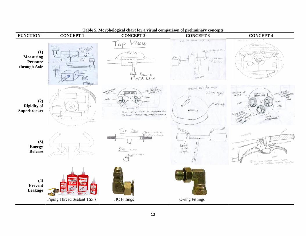
Table 5. Morphological chart for a visual comparison of preliminary concepts
FUNCTION CONCEPT 1 CONCEPT 2 CONCEPT 3 CONCEPT 4
(1)
Measuring
Pressure
through Axle
(2)
Rigidity of
Superbracket
(3)
Energy
Release
(4)
Prevent
Leakage
Piping Thread Sealant TS5’s JIC Fittings
O-ring Fittings
13
Function 1: Being Able to Measure the Pressure through the Axle One of the main functions requested by the sponsor was to be able to measure pressure through the axle
of the bicycle. This is necessary in order to implement the HRBS into a wheelchair and connect the
system to an external high-pressure tank for future terms. This will allow hydraulic fluid to flow from the
low-pressure reservoir to the solenoid housing, where it will flow either into the high-pressure
accumulator in the wheel hub or through the axle and into an external high-pressure tank. To allow the
user to know how much energy they have stored in these high-pressure tanks, a pressure gauge in the
system should read the amount of pressure built up in the axle. Both these necessities may be achieved by
being able to measure the pressure through the axle.
Concept 1: bore extra path through solenoid housing to allow cross-flow This concept for
measuring the pressure through the axle would require an extra path to be bored in the currently existing
solenoid housing to allow for flow into the axle. In the current HRBS, the solenoid housing has three
different paths for the fluid to flow: (1) to the high-pressure accumulator, (2) from the pump, and (3) to
the motor. This concept is to bore another path in this solenoid housing to create a fourth path. This fourth
path would then connect to the axle by a hydraulic line. This would allow the pressurized fluid to flow
into the solenoid housing, through the fourth path, and then through the axle to the hypothetical external
pressure tank. Also, with this fourth path, a pressure gauge can be attached to read the amount of pressure
flowing through this route.
Concept 2: direct flow from separate housing The next idea involves adding a block in the
center of the axle, then having a hole drilled in block along the line of the axle, and drilling another hole
coming in perpendicular to axle. Fluid will flow from the system into the perpendicular hole and out the
axle. The method for getting fluid out of the system was unspecified in this concept. It only concentrates
on the point in the fluid flow where the fluid enters the axle. This idea needs to be combined with one of
the other concepts listed here that focus more on the point in the existing system from which the high
pressure fluid will be coming to the axle.
Concept 3: add piping from outside of solenoid housing Instead of creating another route in
the solenoid housing mentioned as concept 1, this concept suggests creating another route coming off
from the existing piping between the solenoid housing and the high-pressure accumulator. A T-path
would be created for this concept. When the pump pushes the hydraulic fluid, it will flow into the
solenoid housing and into the path that leads to the high-pressure accumulator. Once this accumulator
reaches its maximum capacity, a check valve will block any more flow from entering the accumulator.
Once this valve is initiated, the fluid will then flow from the pump, to the solenoid, to the path leading to
the high-pressure accumulator but instead of entering the accumulator, it will flow down the added T-path
to the axle, and then into the external tank.
Concept 4: external hose through the axle For this concept, the fluid line from the components on
one side of the superbracket is simply extended and threaded through the axle to connect to the high
pressure accumulator on the other side of the superbracket. This concept was developed with the idea that
the objective was to just simply have the fluid line going through the axle. The goal was to create a path
through the axle to allow high pressure fluid to pass through so that an external tank may be integrated in
further projects.
Function 2: Increasing the Stiffness of the Superbracket From discussions with previous teams and the sponsor, the main reason for the failure of the previous
HRBS was determined to be the inability of the superbracket to withstand the torques caused by the
components of the HRBS. When the system was initiated and loads were applied to the system, the
superbracket would flex and cause the gears to misalign and eventually jam. Since all the components are
mounted onto this superbracket, it is vital that the superbracket remains rigid under heavy loads to ensure

14
system functionality. Additionally, preliminary research was done on different materials to compare
which materials would be the best fit for the HRBS. This may be seen in Table 6 below.
Table 6. Comparison table of different materials and their material properties
Material Yield Strength
[MPa]
Ultimate
Strength [MPa]
Density
[g/cm3]
Young’s
Modulus [GPa]
Brass 200 550 5.30 100-125
Aluminum alloy 414 483 2.80 69
Stainless steel AISI 302-Cold
rolled
520 860 8.19 N/A
Copper (99.9%) 70 220 8.92 117
Steel, High strength alloy ASTM 690 760 7.80 200
Titanium alloy 830 900 4.51 105-120
Concept 1: change geometry and thickness of the superbracket One concept was to increase
the thickness of the superbracket, and thus increase the yield strength. However, this idea interfered with
the customer requirement of keeping the weight at a minimum. Therefore this concept was compromised
to change the geometry of the superbracket while increasing the material thickness. Changing the
geometry involves cutting out portions of the superbracket where a yet to be performed Finite Element
Analysis shows the loaded stress levels to be very low. Changing the shape of the superbracket in this
way will reduce the weight added from thickening the material, while maintaining rigidness.
Concept 2: cut slots in superbracket and bend the metal outward Another method of
increasing the stiffness of the superbracket was a suggestion from the sponsor: cut slots in the
superbracket and then bend the metal upward to create a sturdier superbracket.
Concept 3: add metal bars to the areas of high stress By performing basic FEA on the standard
superbracket, locations of maximum stress displacement may be determined. With these locations known,
a rigid bar may be welded to these areas to increase the yield strength of that specific area. The added
rigid bars can be made of a different material with greater stiffness properties than the material used to
manufacture the main body of the superbracket.
Concept 4: add extra material to the areas of high stress Similar to concept 3, this concept is
adding extra thickness to the areas of high stress rather than rigid bars. The areas of high stress would be
determined from thorough FEA analysis of the standard superbracket. The difference between this
concept and concept 3 is manufacturing process. Concept 3 takes a plate and welds bars to the surface,
while this concept would require the plate be milled out of a thicker block, leaving some areas thicker
than others.
Function 3: Method of Releasing Energy The main function of the HRBS is to store the braking energy so that the user can release the stored
energy for acceleration. The method of storing the energy and releasing the energy make up the electrical
subsystem of the HRBS. There are several ways the user could release the stored energy to launch the
bike. Four main concepts were developed to take into account ease of user interface and safety.
Concept 1: two press buttons on each handle of the bicycle Due to the simplicity in wiring a
push button, one idea was to implement two of them into the handlebars of the bicycle. Having two push
buttons will require the user to press both the buttons at the same time to release the energy stored in the
system. This will reduce the safety hazard of the user accidently pushing one button and initiating a
launch unintentionally.

15
Concept 2: a toggle switch with a cap This idea is to have a toggle switch control the releasing of
the stored energy, with one position being off and the other position being on. An additional part to this
concept was adding a hinged cap to place over the toggle switch so it would not be switched on
involuntarily.
Concept 3: one press button on the handle of the bicycle Instead of having two buttons pushed
simultaneously to launch the bike, only one button would need to be pushed. This idea was selected for its
simplicity in the circuit wiring as well as convenience for the user.
Concept 4: a dial switch This concept is to use a dial switch to allow the user to release the stored
energy variably. A dial switch would allow the user to adjust the amount of energy released, correlating
the minimum value on the dial to the minimum speed and the maximum value on the dial to the
maximum speed.
Function 4: Preventing Leakage of the Hydraulic Fluid Among the basic elements of virtually every hydraulic system is a series of fittings for connecting tube,
pipe, and hose to pumps, valves, actuators, and other components. When previous teams created
prototypes of the HRBS, a variety of different connectors and fittings were implemented. Yet, from
several previous teams, leaking of the hydraulic fluid in the system was a problem in areas of connections
and joints. The leakage of the hydraulic fluid is a safety hazard as well as inefficiency in the hydraulic
system. Therefore determining the best way to prevent leakage is vital.
Concept 1: piping thread sealant TS500’s One idea to prevent leakage of the system is to use
piping thread sealant that is capable of restricting high pressures from releasing through the components.
Some previous problems with using glue were the inability for the glue to remain on the component at
such high pressures of the system. This could cause the glue to be ineffective when contacted by the
hydraulic fluid at certain high pressures. Therefore research was conducted to find that TS500 piping
thread sealant was durable enough to handle the maximum pressure of our system (3000 psi). Other
features of this product include: ability to withstand temperatures up to 200 degree and its excellent
solvent resistance. It is also compatible with stainless steel surfaces.
Concept 2: JIC fittings Tightening threads between mating halves of the fitting (or fitting and
component port) forces two mating surfaces together to form a high-pressure seal. Regular 90º pipe
threads are prone to leakage because they are torque-sensitive — over-tightening distorts the threads too
much and creates a path for leakage around the threads. JIC fittings have heads that are tapered at a 37º
angle, and a schematic of this type of fitting may be seen below in Figure 4. JIC fittings rely on the stress
generated by forcing the perfectly tapered heads of the male half of the fitting into the female half or
component port to create a good seal.
Figure 4. Schematic side view of O-ring fitting
Concept 3: O-ring fittings Fittings seal fluid within the hydraulic system by one of two techniques:
all-metal fittings rely on metal-to-metal contact, while O-ring type fittings contain pressurized fluid by
compressing an elastomeric seal.

16
O-ring fittings seat a rubber O-ring between threads and wrench flats around the OD of the male half of
the connector. This may be seen in Figure 5 below. A leak-tight seal is formed against a machined seat on
the female port.
Figure 5. Schematic side view of O-ring fitting
CONCEPT EVALUATION This section will discuss the steps taken to evaluate and then select the preliminary concepts chosen for
each function. A broad evaluation was done by comparing the advantages and disadvantages of each
concept. Once this was accomplished, Pugh Charts were prepared for each function to systematically rate
each concept.
Evaluation of Advantages and Disadvantages To systematically facilitate the evaluation of all the concepts, it was noted that our main functions were
largely independent of each other. Hence, for this design process, advantages and disadvantages of the
four functions for the re-design of the HRBS were evaluated independently from one another. These
qualities are organized in Table 7 below. Further detailed evaluation of the advantages and disadvantages
for each concept are discussed following the table. Note that the explanation for each concept is discussed
in detail in the Concept Generation section starting on page 9.
Table 7. Basic list of advantage and disadvantages of each concept for each function
Advantages Disadvantages
(Function 1)
Measuring the
Pressure
through the
Axle
Cross flow through
solenoid housing Doesn’t require many additional parts May not have enough space
Direct flow from
separate housing Ensures fluid flow May add weight to the system
Path from outside of
solenoid housing Ensures fluid flow Requires additional parts
External line through
the axle Simple Interferes with spokes of the wheel
(Function 2)
Increase
Rigidity of
Superbracket
Change Geometry Reduce the weight of the system May decrease rigidity of superbracket
Slots / Bend Metal Does not require additional material May interfere with components
Add Metal Bars Easy to implement Adds weight
Change Thickness Easy to implement Increases weight of system
(Function 3)
Energy Release
2 Buttons Provides upmost safety Less convenient
Toggle Switch Safe and convenient (Cap) may be bulky
1 Button Simple May accidentally be pressed
Dial Switch Gives the user better speed control Difficult to implement
(Function 4)
Prevent
Leakage
Piping Sealant Easy to implement Will not allow for disassembly
JIC Fittings Highly effective If not assembled correctly, highly
ineffective
O-Ring Fittings Highly effective Rubber o-rings may deteriorate over time
Function 1: allowing pressure to flow through the axle The first concept, where a fourth path is
bored in the solenoid housing, has the advantage of adding a minimal amount of extra components

17
compared to the other concepts. This will reduce the cost of purchasing products and will add the least
amount of weight as well. The disadvantage with this concept is that the space between the current
solenoid housing and the forks of the bicycle is very small. Therefore implementing this extra path to
connect to the axle may overcrowd this area and thus restrict proper movement of the system.
In the second concept listed in Table 7 on page 16, the separate housing will need to be manufactured.
The advantage to this concept is that the block can be manufactured in the shop with proper planning, so
there would be no addition costs to the system. Creating this block would also allow the entrance to the
axle to be placed in an area where the system is less crowded. The disadvantage to this design is finding
space in the existing design to put the new housing in the middle of the axle as well as integrating it into
the superbracket. Since the current design already optimizes the little space available on a children’s
bicycle wheel, choosing this design would require careful planning. As stated in the concept description
on page 11, this concept would need to be combined with another concept to fully achieve the goal set
forth.
In the third concept listed in Table 7, the T-path connected to the already existing path between the
solenoid housing and the high-pressure accumulator, has many more disadvantages than advantages. The
benefit of this system is that it would allow the fluid to flow to the external tank once the high-pressure
accumulator has reached its capacity. The disadvantage associated with this concept is that it would
require extra installation of valves, fittings and piping. This would raise the overall cost of the prototype
and would also increase the size of the system. Having to add these extra components would also add to
the weight of the system, preventing it from being at a minimum of 24lbs.
In the fourth concept listed in Table 7, the addition of a hose routed through the axle, would not be
feasible. This design would have been the most simplistic in re-designing the current HRBS but is
impracticable. The reason for this is because the additional hydraulic line would intersect the moving
spokes of the front wheel. This would interrupt the true spin of the wheel and prevent it from moving.
Function 2: increasing durability of the superbracket In the first concept for this function listed
in Table 7, the changing of the geometry, the advantage includes the weight of the system being reduced
depending on the shape change. Changing the geometry of the system would include cutting off unused
parts of the superbracket and optimizing the space by cutting holes or slots in areas that are unused. This
would reduce the overall weight of the system, yet may also decrease the strength of the superbracket.
Therefore in depth FEA would have to be conducted for this concept to make sure material is removed
only from areas of low stress.
In the second concept listed in Table 7, cutting slots and bending the metal, the advantage would be
changing the strength of the superbracket without adding or reducing any material. Also, since the
original superbracket would be the only thing that would be changing, this in turn would require no
purchase of additional parts, thus resulting in no additional costs. However, the problem with this concept
is that it is difficult to bend metal precisely and also that the bent material may get in the way of other
components.
In the third concept listed in Table 7, adding rigid bars, the advantage is that not a lot of FEA is required.
Since the area that this concept incorporates is only the areas where the maximum displacement occurs,
less FEA would have to be conducted than concept’s one or two. However, this method would increase
the weight of the system as well as increase the cost of the prototype. Also, the addition of extra bars may
require having to change the existing compact assembly to fit the bars.
In the fourth concept listed in Table 7 on page 16, changing the thickness in areas of high stress would be
an advantage by increasing the strength of the superbracket in areas of high torque from when the gears

18
mesh together. Another advantage is the simplicity of implementation. Since this concept is to mill the
superbracket out of a block of material while leaving some parts thicker than others, it would not require
complex designing or planning. The main disadvantages of this concept are the addition of weight to the
system and the lengthy machining process that would be required to mill the superbracket from a block of
metal.
Function 3: method of energy release for the user In the first concept for this function listed in
Table, using two push buttons has the advantage of accounting for safety in regards to a user accidentally
releasing the energy. The system cannot be engaged without both buttons being pushed simultaneously.
Therefore, an unintentional release of the energy has a low risk of happening. The only disadvantage to
this concept is if the user sees it as inconvenient having to push both buttons at the same time. Yet the
drawbacks to the system are minimal compared to the safety advantage it will provide to the user.
Using a toggle switch with a cap, the second concept listed in Table 7, meets similar safety standards as
the first concept. The cap over the toggle switch will guarantee the user won’t initiate the system
accidentally and the switch itself provides simplicity and convenience. However a problem with this
concept is the process of placing the toggle switch and a cap on cylindrical handlebars. Also, this would
require additional parts that would increase the cost of the system as well as the number of overall parts.
The third concept listed in Table 7 is using a single push button instead of two. The major disadvantage
to this design is the accidental pressing of the button by the user would abruptly accelerate the bike. The
advantage to this design would be fewer components are needed and this concept would be easy to
implement. However, safety is paramount over simplicity and convenience.
Using a dial switch, the fourth concept listed in Table 7, would allow the user to vary the energy release
rate in relation to the speed they wanted the acceleration to be. This would provide the user an increased
degree on control over the system. However, the electrical system required by this concept would be
much more complex than the other concepts and thus may be harder to implement. Also, the prices of dial
switches are much higher than push buttons or toggle switches, so the implementation of this concept
would also increase the cost of the prototype.
Function 4: preventing leakage of the hydraulic system Seepage around threads should be
expected when pipe fittings are used in high-pressure hydraulic systems. If the components within
hydraulic systems never had to be removed, connections could be brazed or welded to maximize
reliability. However, it is inevitable that connections must be broken to allow servicing or replacing
components. Therefore, removable fittings are a necessity.
This results in a major disadvantage for the first concept in Table 7 for this function: piping sealant glue.
The advantage to using the piping sealant would be the ease and time efficiency of utilizing the glue but
the glue would not allow for disassembly of the HRBS.
In the second concept listed in Table 7, use of JIC fittings, the advantage would be that tapered JIC
fittings are highly effective in preventing leakage in hydraulic systems. Ultimately, research on the best
fittings for hydraulic systems resulted in this concept and the third concept [9]. For JIC fittings, tightening
the assembly's nut draws the fitting into the 37° flared end of the tubing, resulting in a positive seal
between the flared tube face and the fitting body. Also, JIC fittings are designed for use with thin-wall to
medium-thickness tubing in systems with operating pressures well above 3000 psi. This is more than
adequate for the pressure levels of the HRBS implemented in the children’s bicycle. Additional
advantages include that JIC fittings are suitable for hydraulic systems operating at temperatures from up
to 400° F. This should be able to handle any earthly environmental conditions the HRBS may encounter.
19
JIC fittings are more compact than most other fittings. However, since JIC fittings are tapered, repeated
assembly and disassembly only aggravates the leakage problem by distorting threads.
Fittings with O-ring seals, the third concept in Table 7 on page 16, offer a number of advantages over
metal-to-metal fittings. While under-or over-tightening any fitting can allow leakage, all-metal fittings are
more susceptible to leakage because they must be tightened to within a higher, yet narrower torque range.
This makes it easier to strip threads or crack or distort fitting components, which prevents proper sealing.
The rubber-to-metal seal in O-ring fittings does not distort any metal parts and provides a tangible "feel"
when the connection is tight. All-metal fittings tighten more gradually, so technicians may have trouble
detecting when a connection is tight enough but not too tight.
On the other hand, O-ring fittings are more expensive and care must be exercised during installation to
ensure that the O-ring doesn't fall out or get damaged when the assemblies are connected. In addition, O-
rings are not interchangeable among all couplings. Selecting the wrong O-ring or reusing one that has
been deformed or damaged can invite leakage. Once an O-ring has been used in a fitting, it is not
reusable, even though it may appear free of distortions.
Systematic Evaluation Once these comparisons were systematically arranged and the advantages and disadvantages were
thoroughly discussed, Pugh charts were drawn up for each function to select the option that gave the best
overall performance based on the customer requirements. These may be seen below in Tables 8-11 (pages
19-20). The customer requirements were derived from the QFD diagram and the requests from the
sponsor. The Pugh charts helped systematically compare each concept to determine whether the possible
design could satisfy any of the customer requirements. A ―+‖ sign is given when the criterion could be
satisfied easily, a ―0‖ is given when the criterion may or may not be satisfied easily and a ―-‖ is given
when the criterion could not be satisfied at all. The resulting scores from the Pugh charts aided in the final
selection process for the different functions.
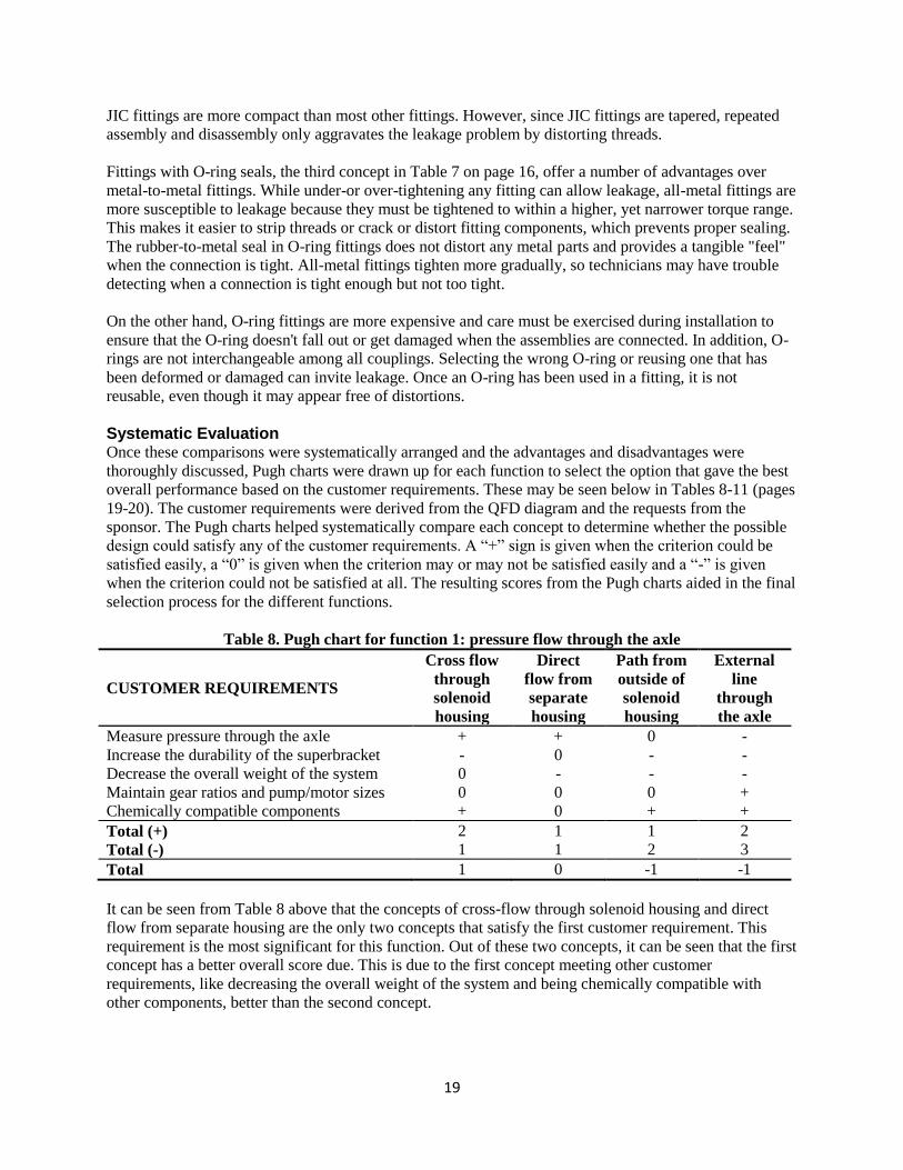
Table 8. Pugh chart for function 1: pressure flow through the axle
CUSTOMER REQUIREMENTS
Cross flow
through
solenoid
housing
Direct
flow from
separate
housing
Path from
outside of
solenoid
housing
External
line
through
the axle
Measure pressure through the axle + + 0 -
Increase the durability of the superbracket - 0 - -
Decrease the overall weight of the system 0 - - -
Maintain gear ratios and pump/motor sizes 0 0 0 +
Chemically compatible components + 0 + +
Total (+) 2 1 1 2
Total (-) 1 1 2 3
Total 1 0 -1 -1
It can be seen from Table 8 above that the concepts of cross-flow through solenoid housing and direct
flow from separate housing are the only two concepts that satisfy the first customer requirement. This
requirement is the most significant for this function. Out of these two concepts, it can be seen that the first
concept has a better overall score due. This is due to the first concept meeting other customer
requirements, like decreasing the overall weight of the system and being chemically compatible with
other components, better than the second concept.

20
Table 9. Pugh chart for function 2: increasing the rigidity of the superbracket
CUSTOMER REQUIREMENTS Change
geometry
Slots/bend
metal
Add metal
bars
Change
thickness
Measure pressure through the axle - - - -
Increase the durability of the superbracket 0 + + +
Decrease the overall weight of the system + 0 - -
Maintain gear ratios and pump/motor sizes 0 0 0 +
Chemically compatible components + + + +
Total (+) 2 2 2 3
Total (-) 1 1 2 2
Total 1 1 0 1
As discussed previously, the superbracket is one component that is exposed to most of the torques and
stresses that are generated when the bike in motion. When comparing the different concepts in Table 9
above, it can be seen that the concepts of changing the geometry, cutting slots to bend the metal and
changing the thickness scored equally well. Thus, the team has taken into consideration all three concepts
and potential ways to combine all three characteristics.
Table 10. Pugh chart for function 3: method of releasing the pressure
CUSTOMER REQUIREMENTS 2 buttons toggle switch 1 button Dial switch
Measure pressure through the axle
Increase the durability of the superbracket
Decrease the overall weight of the system
Maintain gear ratios and pump/motor sizes + + + +
Chemically compatible components 0 0 0 0
Total (+) 1 1 1 1
Total (-) 0 0 0 0
Total 1 1 1 1
It can be seen in Table 10 above that all the concepts developed for this function have scored equally and
in the same customer requirement categories. Therefore, all of these concepts will be given equal
consideration in the final design selection, and the advantages and disadvantages of each will be
compared more thoroughly.
Table 11. Pugh chart for function 4: preventing leakage
CUSTOMER REQUIREMENTS Piping Sealant JIC Fittings O-Ring Fittings
Measure pressure through the axle - - -
Increase the durability of the superbracket - + +
Decrease the overall weight of the system + 0 0
Maintain gear ratios and pump/motor sizes + 0 0
Chemically compatible components 0 + +
Total + 2 2 2
Total - 2 1 1
Total 0 1 1
In Table 11 above, the JIC fittings and O-ring fittings scored equally and better over piping sealant. Both
the JIC and O-ring fittings also scored equally in the same customer requirement categories. Thus, both
these concepts may be utilized in the HRBS where they would fit the best.
21
CONCEPT SELECTION The highest ranked concepts for each function, determined by the Pugh Charts in the previous section,
were combined and/or refined to develop final concepts. Based on further analysis of these concepts and
their attributes, final selections were made and the Alpha Design was created. The Alpha Design is in the
preliminary stages, and some of the choices are subject to change pending Finite Element Analysis
(FEA).
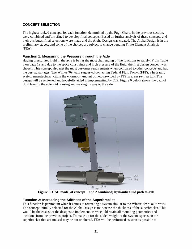
Function 1: Measuring the Pressure through the Axle Having pressurized fluid in the axle is by far the most challenging of the functions to satisfy. From Table
8 on page 19 and due to the space constraints and high pressure of the fluid, the first design concept was
chosen. This concept also met the most customer requirements when compared to other concepts and had
the best advantages. The Winter ’09 team suggested contacting Federal Fluid Power (FFP), a hydraulic
system manufacturer, citing the enormous amount of help provided by FFP in areas such as this. The
design will be reviewed and hopefully aided in implementing by FFP. Figure 6 below shows the path of
fluid leaving the solenoid housing and making its way to the axle.
Figure 6. CAD model of concept 1 and 2 combined; hydraulic fluid path to axle
Function 2: Increasing the Stiffness of the Superbracket This function is paramount when it comes to recreating a system similar to the Winter ’09 bike to work.
The concept initially selected for the Alpha Design is to increase the thickness of the superbracket. This
would be the easiest of the designs to implement, as we could retain all mounting geometries and
locations from the previous project. To make up for the added weight of the system, spaces on the
superbracket that are unused may be cut or altered. FEA will be performed as soon as possible to

22
determine the validity of this final design. Figure 7 shows the basic shape of the superbracket with a few
slots for components missing. A finalized CAD model will be created once FEA is performed.
Figure 7. CAD model of superbracket for HRBS
Function 3: Method of Energy Release While other approaches were investigated, it has been decided to stick with the design implemented by
the Winter ’09 team. The need to depress a button with each hand not only protects the user from an
accidental launch, but it also requires a level of user interaction and attention that a system as possibly
dangerous as this warrants. Figure 8 [10] displays an electrical schematic for the wiring necessary to
implement two buttons for the HRBS. Since the modified bike was originally equipped with both front
and rear hand brakes, the existing front brake cable will be connected to an electrical toggle switch,
labeled OFF-(ON) toggle in Figure 8, that activates the pump clutch. The two push buttons in the diagram
will be the aforementioned buttons for each handle. These buttons and switches will be momentary, so
that their function terminates once the button or switch is released.
Figure 8. Wiring diagram for two buttons needed to be pushed simultaneously for the HRBS [10]

23
Function 4: Preventing Leakage of the Hydraulic System At the recommendation of former project members, pipe sealants will be avoided if at all possible. To
keep the system from leaking, both JIC and O-ring hydraulic fittings will be used. These fittings are also
the most commonly used in hydraulic systems [9]. To ensure proper installation of these fittings, previous
team members and professionals will be involved in the hydraulic system assembly process. If installed
correctly, these fittings will protect against any leakage for a very long time. Therefore, the professionals
at Federal Fluid Power will be heavily leaned upon for their expertise in this area.
ENGINEERING DESIGN PARAMETER ANALYSIS For the final phase of designing, engineering parameter analysis was executed on the final design of the
HRBS and its subsystems. This section details the analysis on these subsystems including: modeling the
entire HRBS, the motor and pump, the gear transmission, hydraulic system, and the overall bike. The
analysis on these subsystems was conducted extensively by the Winter ’09 HRBS team [10] and was
examined and re-performed for the current HRBS design. The engineering analysis by the previous team
was closely followed and relied on since most of the components from previous generations were to be
used for the new HRBS. Any re-performance of their engineering analysis was conducted to take into
account any new designs and components that the old HRBS’s did not contain.
For any commercially purchased components, analysis on their specifications was conducted. For
specification sheets, please refer to the safety report. The analysis on all non-commercially purchased
products includes FEA, CAD modeling and FMEA analysis. The FEA and CAD models may be seen in
Appendix F and G, respectively. The FMEA analysis may be seen in the safety report correlating to this
project. The bill of materials (BOM) for any purchased parts may also be seen in Appendix A.
System Modeling One of Winter ’09 Team 24’s goals was to more rigorously define the theoretical model of the HRBS
through the use of computer simulation (Simulink), something that had not been attempted in previous
generations [10]. Though they have used it primarily to evaluate performance characteristics and design
selection of the HRBS, their model will also provide a valuable source of information to existing research
as well as to future works.
The theoretical model is constructed around the pump and motor transmission, from which the other
subsystems developed overtime. The architecture of the theoretical model is shown in Figure 9 with the
complete model of the transient system behavior shown in Figure 10 on page 24. All variables used in the
model are listed in Table 12 on page 24.
Figure 9. Theoretical model of the HRBS

24
Figure 10. Computer Simulink model of theoretical HRBS system [10]
Table 12. A list of the variables used in the calculations for the engineering analysis
Variable Subsystem Description
F12 Pump/Motor Transmission Tangential force between motor or pump gear to 2nd
gear on first
reduction
F34 Pump/Motor Transmission Tangential force between main gear and 1st gear on 2
nd reduction
I1 Pump/Motor Transmission Rotational inertia of pump or motor gear
I2 Pump/Motor Transmission Rotational inertia of 2nd
gear on first reduction
I3 Pump/Motor Transmission Rotational inertia of clutched gear
I4 Pump/Motor Transmission Rotational inertia of main gear
I5 Pump/Motor Transmission Rotational inertia of meshed 5th
gear from other transmission
Iw Bike System Inertial of front and rear wheel
R1 Pump/Motor Transmission Pitch Radius of pump or motor gear
R2 Pump/Motor Transmission Pitch Radius of 2nd
gear on first reduction
R3 Pump/Motor Transmission Pitch Radius of clutched gear
R4 Pump/Motor Transmission Pitch Radius of main gear
R5 Pump/Motor Transmission Pitch Radius of meshed 5th
gear from other transmission
M Bike System Total mass of bike with rider
P Performance curves Pressure on high side of pump or motor
Pc Hydraulic System Charge pressure for motor system
Pg Hydraulic System Instantaneous nitrogen gas pressure
PnR Hydraulic System Pre-charge pressure of hydraulic accumulator
Q Hydraulic System Flow rate of fluid into the accumulator
Rw Bike System Radius of front and rear wheel
Tin Pump/Motor Transmission
Performance curves
Torque applied by motor and pump shaft to transmission
Tout Pump/Motor Transmission Torque applied to wheels
Ts Pump/Motor Transmission Torque applied to clutched shaft
Vf Hydraulic System Instantaneous fluid volume
Vfo Hydraulic System Initial fluid volume
Vg Hydraulic System Instantaneous nitrogen gas volume
VnR Hydraulic System Volume of nitrogen gas for empty accumulator
a Bike System Acceleration of the bike
ω1 Pump/Motor Transmission Angular Speed of pump or motor shaft and gear
ω2 Pump/Motor Transmission Angular Speed of 2nd
gear on first reduction
ω3 Pump/Motor Transmission Angular Speed of clutched gear
ω4 Pump/Motor Transmission Angular Speed of main gear and front wheel
ω5 Pump/Motor Transmission Angular Speed of meshed 5th
gear from other transmission

25
Since the current HRBS is to be a refined version of the previous model, it was decided to use the
theoretical model that had been developed by the previous year’s team. Each subsystem in the model was
designed separately and with detail to allow future teams to input different initial conditions.
The input values for the Simulink model include the accumulator size and pre-charge, the inertias of all
mechanical components, bike, and rider, and the individual gear sizes. The output values resulted in being
the accumulator pressure and fluid storage, the torques and/or forces on all mechanical components and
the bike acceleration speeds. Since the new HRBS was designed after the previous generation, many of
the components and specifications remained the same. The only difference was the inertia of the bike
being different due to the bike for the current system having a slightly larger mass.
When re-simulating the previous team’s model, the result was Figure 11 below. With this simulation, the
bike’s performance could be estimated using a variety of initial speeds.
Figure 11. Diagram from running the Simulink model provided by the previous Winter ‘09 team
[10]
Motor and Pump Performance Curves The motor and pump are two critical devices in our system. The pump is needed when the bike
decelerates and it uses the bike’s kinetic energy to move the hydraulic fluid from the low pressure
reservoir to the high-pressure accumulator. The motor is used to accelerate the bike when the HRBS is
engaged. As a result, the performances of the two devices are critical in analyzing the HRBS. The motor
and pump have two different inputs; with the motor having different rotational speeds and the pump
having different pressure inputs. Due to this, they generate different torques, which are used to stop or
accelerate the bike. To ensure the bike has the desirable accelerating or decelerating rates as specified by
the engineering specifications in Table 12 on page 24, accurate performance curves of the two devices are
required. Performance curves of these two devices will ensure the motor or the pump can produce the
torques we need to achieve the targeted acceleration and deceleration speeds. Fortunately, the steady-state
performance curves for the pump and motor were provided by the manufacturer, Marzocchi. These can be
seen in Figure 12 on page 26. These performance curves can help locate the specific acceleration or
deceleration with varying flow rate input values.

26
Figure 12. Motor and pump performance curves for the HRBS
After examining the two curves above carefully with the operating pressure for the HRBS, the operating
pressure of the HRBS is above the values shown in the two figures. This meant most of the data would
have to be extrapolated and thus, a curve fit was considered. As shown in the two figures above, the
torque on the pump and motor shafts are strongly dependent on pressure input, and less dependent on
rotational speed. Therefore to extrapolate the best fit line, it was assumed the torque was a strong function
of pressure and would vary with respect to pressure. The variation due to speed was assumed to be a
percentage change from the average torque at the constant baseline pressure curve. The baseline pressure
curve is defined as the constant pressure line from which the curve fits are extrapolated. The baseline is
selected to make sure the predicted performance curve matches the actual performance curve as closely as
possible. Based on the consistent shapes of the performance curves shown in the two figures above, the
quadratic function can be used to model the speed variation’s effect on the performance curve. As a
result, Eq. 1 below was used to describe the predicted performance curve where ω is the angular speed of
the motor or pump shaft (rpm), P is the operating pressure of the motor and pump, Pbaseline is the baseline
pressure, and the variables A, B, C, d, e are the fit parameters.
𝑇 𝜔, 𝑃 =𝐴𝜔2+𝐵𝜔+𝐶
𝑑+𝑒𝑃𝑏𝑎𝑠𝑒𝑙 𝑖𝑛𝑒(𝑑 + 𝑒𝑃) (Eq. 1)
The table below shows the values of the fit parameters. The baseline pressures were chosen such that the
extrapolated curves matched as closely as possible to the actual performance curves.
Table 13. Curve fit parameters for motor and pump
Motor Pump
Pbaseline 230 Bar 190 Bar
A 1.4 × 10⁻⁸ 2.6 × 10⁻⁸
B −3.0 × 10⁻⁵ −5.3 × 10⁻⁵
C 2.216 2.3
D 0.2 0.12
E 0.01748 0.01

27
Gear Reductions The sponsor specifically requested the new HRBS use the same gears implemented in the previous
generation of the HRBS. Therefore since the exact same gears from the old prototype were to be
integrated into the new HRBS, the gear reduction analysis from the Winter ’09 Team 24 final report [10]
was looked at in preparation. Figure 13 shows the geometry of the pump and motor transmission model.
The transmission is a double reduction system (1 to 2 and 3 to 4) that amplifies the torque transmitted to
the front wheel in two stages.
Figure 13. Geometry of the pump and motor transmission model
Using free body diagrams on the transmission model, the corresponding dynamics of each gear were
determined and expressed by Eqs. 2-5. The variables are defined in Table 12 on page 24.
𝑇𝑖𝑛 − 𝐹12𝑅1 = 𝐼1𝜔 1 (Eq.2)
𝐹12𝑅2 − 𝑇𝑠 = 𝐼2𝜔 2 (Eq. 3)
𝑇𝑠 − 𝐹34𝑅3 = (𝐼2 + 𝐼𝑠)𝜔 3 (Eq. 4)
𝐹34𝑅4 − 𝑇𝑜𝑢𝑡 = (𝐼4 + 𝐼5 𝑅4
𝑅5
2)𝜔 4 (Eq. 5)
Although the equations above could have been simplified by algebraically combining them together, this
was decided against in order to create separate subsystems for each gear. Doing this offered the ability to
incorporate additional information, such as frictional losses of tooth grinding, more efficiently if the need
arises. The reason for the inclusion of the 5th
gear in the above equations and Figure 13 is because this is
the satellite gear of the transmission not in operation. Though the two transmissions are independent, this
satellite gear is meshed and will always rotate when either transmission is active. Alongside the dynamic
analysis, a kinematic analysis reveals the mechanical reduction of the system, as shown in Eq. 6 [10].
𝜔1 =𝑅2
𝑅1𝜔2 =
𝑅2
𝑅1𝜔3 =
𝑅2
𝑅1
𝑅4
𝑅3𝜔4 (Eq. 6)
Utilizing Eqs. 2-6, Winter ’09 Team 24 formed a transmission Simulink model for the motor and pump,
which may be seen in Appendix C.

28
Transmission tuning analysis With an automobile, one must tune the transmission to obtain the
highest efficiency from the engine. The HRBS was taken to be no different. Utilizing the Simulink model
provided from Winter ’09 Team 24 [10], different gear reductions of the transmission were tested to tune
the system. The observed behavior of the system is documented in Table 14 below for higher and lower
reductions.
Table 14. Observations when implementing higher or lower reductions on the gear Simulink model
Reduction Changes Pump System Behavior Motor System Behavior
Higher Reductions
- Lower final charge pressure
- Larger pump shaft speed
- Larger deceleration
- Larger loadings on gears
- Slightly higher final speed
- Larger motor shaft speed
- Larger acceleration
- Larger loadings on gears
Lower Reductions
- Larger final charge pressure
- Lower pump shaft speed
- Lower deceleration
- Lower loadings on gears
- Slightly lower final speed
- Lower motor shaft speed
- Lower acceleration
- Lower loadings on gears
Based on the information presented in the table above, it was arguable that to maximize performance, the
lowest gear reduction on the pump system would acquire the largest accumulator pressure. Also having
the highest gear reduction on the motor system would take advantage of the higher final speed. However,
there are limitations. For one, the high accumulator pressure is limited to the design constraint of 4200
psi. This limited how low of a reduction the pump side could have. Another constraint is that the
maximum operating speed of the pump and motor is 7000 rpm. This places an upper limit on possible
gear reductions for the HRBS. Further complicating the matter is the fact that the maximum acceleration
and decelerations levels are limited to those levels comfortable to a wheelchair user. These were
previously determined by the sponsor David Swain and are listed in the engineering specifications in
Table 2 on page 8. Testing stock gear sizes; a gear reduction of 17.5:1 for both the pump and motor
transmission was determined to satisfy all design constraints. This gear reduction was calculated using the
values in Table 15 below and Eq. 2-6 on page 27. The same reduction was chosen for both the pump and
motor to reduce the number of machining operations required for different gear geometries. Although this
sacrifices some performance on the motor side, such as resulting in a slightly lower final speed, it does
not outweigh the benefits of simpler machining schedules as well as reduced loadings on the transmission
components.
Table 15. Gear reduction and sizes
Pump Gear Reduction To
Wheel
Motor Gear Reduction
G1 G2 G3 G4 G3 G2 G1
1‖ 3.5‖ 1‖ 5‖ 1‖ 3.5‖ 1‖
Final Pump Reduction 17.5:1 Final Motor Reduction 17.5:1
Pump and motor system losses System losses are important to discuss since they directly impact
the validity of system models and analysis. System losses that were not taken into account for the pump
and motor analysis include frictional losses and stored deformation energy of the meshed gear teeth. Also,
frictional losses in the clutch (that holds G3) and the frictional losses in all bearings were not considered.
For the performance curves, information uncertainty associated with back calculating transient behavior
from steady-state was not considered.
Bike System The analysis of the bike system as a whole was conducted using free body diagram (FBD) analysis. The
FBD may be seen in Figure 14 on page 29, from which the governing equations of the bike were

29
determined by Eq. 7 below. The variables in Eq. 7 are defined in Table 12 on page 24. Since this term’s
prototype was to be implemented in a bike, as requested by the sponsor, the FBD was done on a bike as
oppose to a wheelchair. Although, the next term that receives this project should conduct FBD analysis on
a wheelchair.
Figure 14. FBD of the bicycle
𝑇𝑜𝑢𝑡 = (2𝐼𝑤 + 𝑀𝑅𝑤2 )
𝑎
𝑅𝑤 (Eq.7)
It is important to note that the FBD analysis assumes rolling without slip, that is, the bike does not skid
during operation. Though this might be added later to validate the system model, it has not been included
since rolling without slip generates the greatest loadings, making them useful for designing against
failure. Also, since the front wheel is rigidly attached to the fourth gear of the transmission, its angular
speed is ω4. The Simulink model of the bike system created by Winter ’09 Team 24 may be seen in
Appendix J.
Bike system losses System losses are important to discuss since they directly impact the validity of
system models and analysis. System losses that were not taken into account for modeling the bike include
frictional losses in all the bearings. Also air drag and vibration of any components were not taken into
account.
Hydraulic System Since the same hydraulic components were used for the current HRBS as the previous generation (exact
same high-pressure accumulator, pressure-relief valve, check valve, filter), the hydraulic system analysis
was taken from the Winter ’09 Team 24 final report [10]. The hydraulic accumulator was modeled under
the assumption that the nitrogen gas inside the accumulator behaved isothermally. This is a reasonable
assumption, as there shouldn’t be significant temperature variations in the accumulator during operation.
Utilizing conservation laws, the fluid and gas behavior of the fluid during operation was able to be
determined and are expressed by Eqs. 8-9 below and Eqs. 10-11 on page 30. Definitions of the variables
used in these equations are found in Table 12 on page 24.
𝑃𝑔𝑉𝑔 = 𝐶𝑜𝑛𝑠𝑡𝑎𝑛𝑡 = 𝑃𝑛𝑅𝑉𝑛𝑅 (Eq. 8)
𝑉𝑔 = 𝑉𝑛𝑅 − 𝑉𝑓 (Eq. 9)

30
𝑉𝑓 − 𝑉𝑓𝑜 = 𝑄𝑑𝑡𝑡
0 (Eq. 10)
𝑉𝑓𝑜 = (1 −𝑃𝑛𝑅
𝑃𝑐)𝑉𝑛𝑅 (Eq. 11)
The flow rate through the system is dependent on the displacement of the pump and motor if no energy
losses in the pipes are assumed. The manufacturer of the high-pressure accumulator, Marzocchi, also
included flow rate curves [11] with the performance curves. By mapping these curves, as seen in Figure
15, a method of relating angular speed of the pump and motor to the flow rate was found. A linear curve
fit for the flows was chosen. Here Q is the flow rate in L/min and ω is the angular speed of the
pump/motor shaft in rpm. The corresponding fit parameter for both the motor and pump was a = 0.00051
for the motor and a = 0.000635 for the pump.
𝑄 = 𝑎𝜔 (Eq. 12)
Figure 15. Pump and motor flow curves
Hydraulic system losses System losses are important to discuss since they directly impact the
validity of system models and analysis. System losses that were not taken into account for modeling the
hydraulic system include entrance/exit effects at small openings such as at the valves, pump, motor,
accumulator, and fittings. Air pockets and or instantaneous cavitations due to motor/pump activity (model
assumes fluid is continuous and is present at all times in the lines) was not taken into account. Heat and
viscous losses in lines and hydraulic accumulators were also not considered when modeling the hydraulic
system. It was determined that for automatic transmission fluid traveling through a 90º bend of a steel
pipe diameter of 0.25‖, a pressure drop of 0.03 psi would result [12]. Since this value is very minimal,
this was also omitted when modeling the hydraulic system.
Customer Requirement Calculations The sponsor requested to determine the energy loss in fluid flow for a 90º bend and the flow rate needed
to allow a wheelchair to match speeds of electric powerchairs. As mentioned above, it was determined
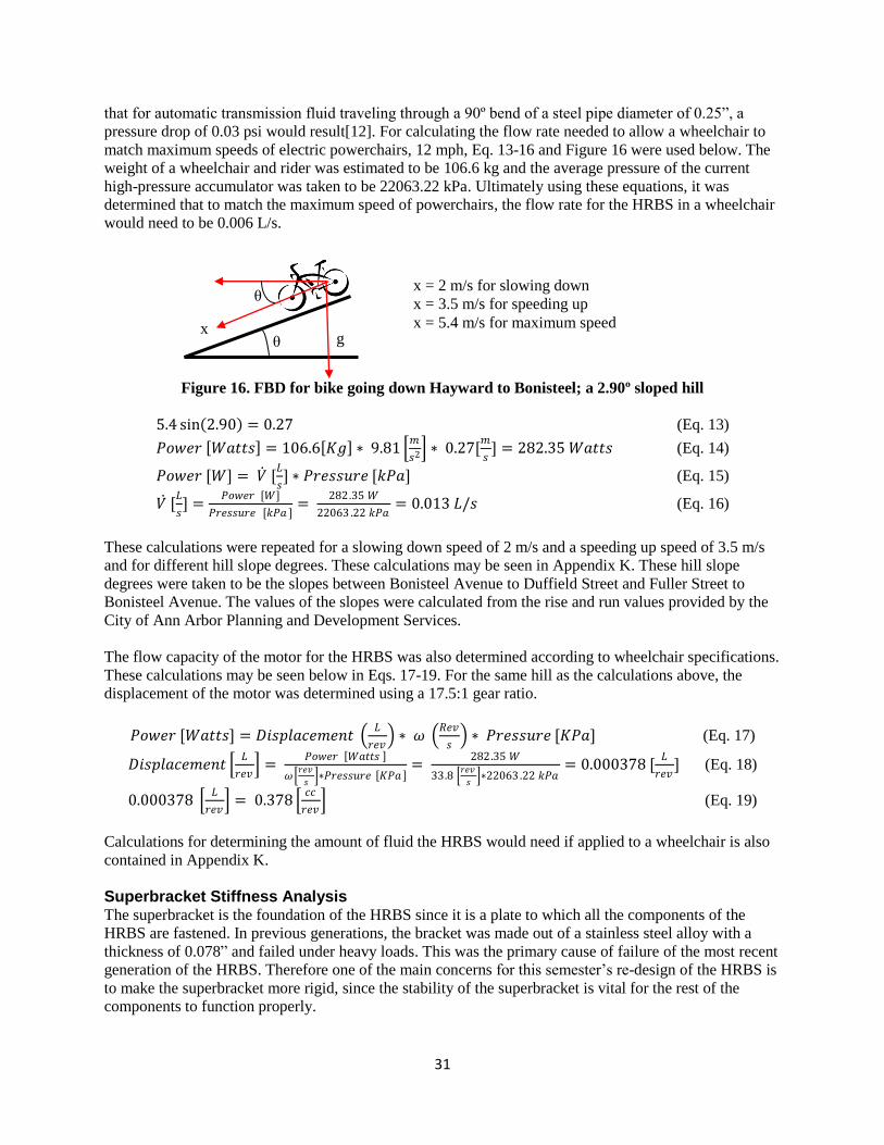
31
that for automatic transmission fluid traveling through a 90º bend of a steel pipe diameter of 0.25‖, a
pressure drop of 0.03 psi would result[12]. For calculating the flow rate needed to allow a wheelchair to
match maximum speeds of electric powerchairs, 12 mph, Eq. 13-16 and Figure 16 were used below. The
weight of a wheelchair and rider was estimated to be 106.6 kg and the average pressure of the current
high-pressure accumulator was taken to be 22063.22 kPa. Ultimately using these equations, it was
determined that to match the maximum speed of powerchairs, the flow rate for the HRBS in a wheelchair
would need to be 0.006 L/s.
Figure 16. FBD for bike going down Hayward to Bonisteel; a 2.90º sloped hill
5.4 sin 2.90 = 0.27 (Eq. 13)
𝑃𝑜𝑤𝑒𝑟 𝑊𝑎𝑡𝑡𝑠 = 106.6 𝐾𝑔 ∗ 9.81 𝑚
𝑠2 ∗ 0.27[𝑚
𝑠] = 282.35 𝑊𝑎𝑡𝑡𝑠 (Eq. 14)
𝑃𝑜𝑤𝑒𝑟 [𝑊] = 𝑉 [𝐿
𝑠] ∗ 𝑃𝑟𝑒𝑠𝑠𝑢𝑟𝑒 [𝑘𝑃𝑎] (Eq. 15)
𝑉 [𝐿
𝑠] =
𝑃𝑜𝑤𝑒𝑟 [𝑊]
𝑃𝑟𝑒𝑠𝑠𝑢𝑟𝑒 [𝑘𝑃𝑎 ]=
282.35 𝑊
22063 .22 𝑘𝑃𝑎= 0.013 𝐿/𝑠 (Eq. 16)
These calculations were repeated for a slowing down speed of 2 m/s and a speeding up speed of 3.5 m/s
and for different hill slope degrees. These calculations may be seen in Appendix K. These hill slope
degrees were taken to be the slopes between Bonisteel Avenue to Duffield Street and Fuller Street to
Bonisteel Avenue. The values of the slopes were calculated from the rise and run values provided by the
City of Ann Arbor Planning and Development Services.
The flow capacity of the motor for the HRBS was also determined according to wheelchair specifications.
These calculations may be seen below in Eqs. 17-19. For the same hill as the calculations above, the
displacement of the motor was determined using a 17.5:1 gear ratio.
𝑃𝑜𝑤𝑒𝑟 [𝑊𝑎𝑡𝑡𝑠] = 𝐷𝑖𝑠𝑝𝑙𝑎𝑐𝑒𝑚𝑒𝑛𝑡 𝐿
𝑟𝑒𝑣 ∗ 𝜔
𝑅𝑒𝑣
𝑠 ∗ 𝑃𝑟𝑒𝑠𝑠𝑢𝑟𝑒 [𝐾𝑃𝑎] (Eq. 17)
𝐷𝑖𝑠𝑝𝑙𝑎𝑐𝑒𝑚𝑒𝑛𝑡 𝐿
𝑟𝑒𝑣 =
𝑃𝑜𝑤𝑒𝑟 𝑊𝑎𝑡𝑡𝑠
𝜔 𝑟𝑒𝑣
𝑠 ∗𝑃𝑟𝑒𝑠𝑠𝑢𝑟𝑒 𝐾𝑃𝑎
= 282.35 𝑊
33.8 𝑟𝑒𝑣
𝑠 ∗22063 .22 𝑘𝑃𝑎
= 0.000378 [𝐿
𝑟𝑒𝑣] (Eq. 18)
0.000378 𝐿
𝑟𝑒𝑣 = 0.378
𝑐𝑐
𝑟𝑒𝑣 (Eq. 19)
Calculations for determining the amount of fluid the HRBS would need if applied to a wheelchair is also
contained in Appendix K.
Superbracket Stiffness Analysis The superbracket is the foundation of the HRBS since it is a plate to which all the components of the
HRBS are fastened. In previous generations, the bracket was made out of a stainless steel alloy with a
thickness of 0.078‖ and failed under heavy loads. This was the primary cause of failure of the most recent
generation of the HRBS. Therefore one of the main concerns for this semester’s re-design of the HRBS is
to make the superbracket more rigid, since the stability of the superbracket is vital for the rest of the
components to function properly.
θ g
θ
x
x = 2 m/s for slowing down
x = 3.5 m/s for speeding up
x = 5.4 m/s for maximum speed

32
Special attention was paid to the stress and moment distribution on the superbracket to analyze the
deformation under these loads and to prevent the gears from potentially jamming. Therefore initially,
FEA analysis was performed on the old bracket to determine where the maximum displacements
occurred. A CAD model of this analysis can be seen in Appendix F. This would aid in choosing whether
the geometry needed to change or the thickness needed to change for the alpha design of the superbracket.
Since the previous HRBS’s superbracket geometry optimized space, the alpha design was chosen to
increase the thickness of the entire superbracket to 0.1‖. Then, in the areas of maximum stress, an
additional thickness of 0.15‖ would be added. The material would also be a 1022 AISI steel alloy due to
its high yield strength at a reasonable cost, as compared in Table 6 on page 14.
FEA analysis was conducted on the alpha design for the superbracket and can be seen below in Figure 17.
FEA analysis was done on the superbracket with the clutch stabilizer included, since the clutch stabilizer
acts to spread certain forces out over a larger area, minimizing the stress those forces could cause. The
locations of the displacements between the old and new superbracket are the same, yet increasing the
thickness has decreased the magnitude of the displacement by 90% compared to the old design. The
maximum stress on the new design has decreased by over 50%.
(a) (b)
Figure 17. New superbracket FEA on a) maximum stress and b) displacement in Autodesk Inventor
Pro 2010
FINAL DESIGN DESCRIPTION The final design of the HRBS consists of the hydraulic system, powertrain, superbracket, and the re-
designed solenoid housing. Among the four subsystems, the hydraulic system and powertrain have been
well developed by previous HRBS teams, so these will be discussed briefly. The re-design of the
superbracket, axle, and solenoid housing have been performed to achieve the more important customer
requirements, as listed in Table 1 on page 7. This section of the report describes the final design of the
new HRBS.
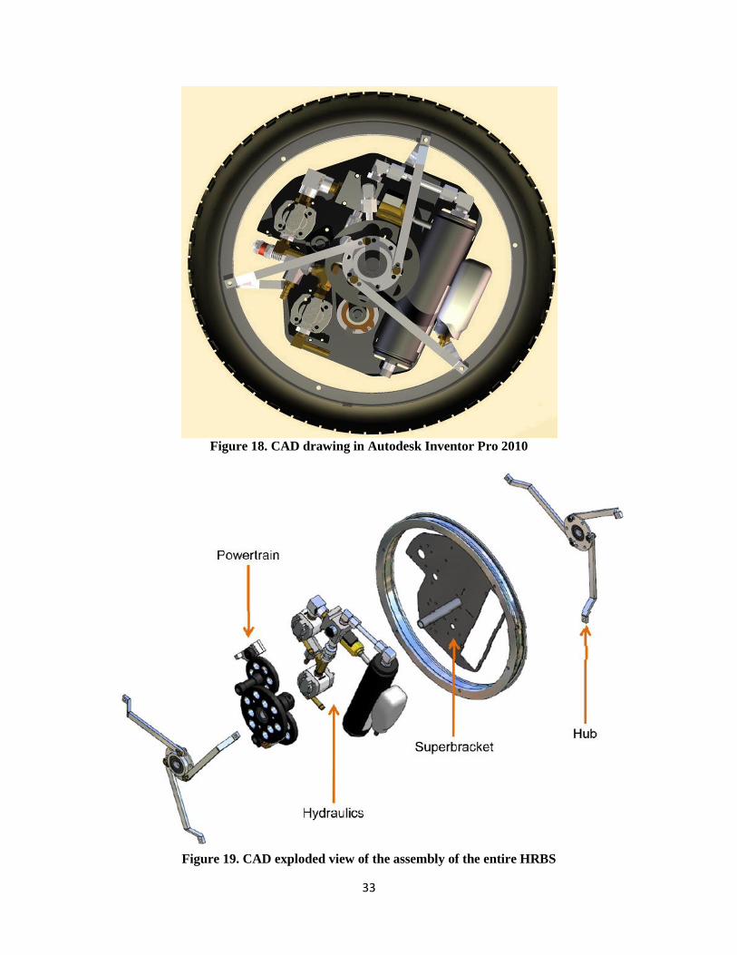
33
Figure 18. CAD drawing in Autodesk Inventor Pro 2010
Figure 19. CAD exploded view of the assembly of the entire HRBS

34
Hydraulic System Within the hydraulic system, the two main sub-functions are braking and accelerating. A schematic can
be seen below in Figure 20 that displays the route of the hydraulic fluid for when the system is braking or
when the system is launching. Low-pressure fluid is traveling through plastic hydraulic tubing, while high
pressure fluid travels through steel hydraulic lines.
Also discussed in this section will be the components that affiliate directly with the hydraulic fluid
throughout the system. This includes the axle (part of the new design), check valve, filter, relief valve,
two-way cartridge solenoid, fittings and tubing, high-pressure accumulator, and the low-pressure
reservoir. For the suppliers of the commercially purchased parts, please see the safety report correlated to
this project.
Figure 20. Schematic of the hydraulic flow throughout the HRBS
Braking One function of the hydraulic system is storing the bike or wheelchair’s kinetic energy in the
high-pressure accumulator. When the bike or wheel chairs brakes are engaged, this causes the clutch to
rotate a gear, which in turn rotates another gear attached to the pump. This activates the pump which then
consumes the kinetic energy of the bike or the wheel chair to move the hydraulic fluid from the low
pressure reservoir, through a filter and to the solenoid housing. The fluid then flows into the high-pressure
reservoir where it is stored. The function of the filter is to prevent the micro-particulars in the hydraulic
fluid from entering the rest of the system to extend hydraulic system lifetime.
Accelerating The other function of the hydraulic system is using the stored energy in the high-pressure
accumulator to accelerate the bike. When the user pushes the button to release the energy stored in the
bike or wheel chair, the circuit terminal on the solenoid valve activates the solenoid housing. This opens
the two-way valve to allow the hydraulic fluid to flow from the accumulator to the motor, but not back
into the pump. From the design of the powertrain, the hydraulic energy stored in the high-pressure
accumulator is transferred to the kinetic energy by the motor. Once the fluid flows through the motor, this
will cause a gear attached to the motor to spin forward. This gear will mesh with the rest of the powertrain
that causes the drive gear to rotate forward, ultimately causing the bicycle to accelerate forward. Once the
fluid travels through the motor, it stores in the low-pressure reservoir again.

35
Check valve The function of the check valve is to prevent fluid from flowing back into the pump when
moving from the high-pressure accumulator to the solenoid housing. The same check valve that the
previous HRBS used will be used for the new HRBS as well, per the sponsor’s suggestion. This valve is a
poppet type 316 stainless steel check valve. It has two ¼‖ NPT male connections on each end with a
pressure rating of 6000 psi. This check valve is chosen because it will be placed in the high-pressure
section of the hydraulic system. Stainless steel was opted as it can contain pressures up to 4000 psi and a
valve that was rated for 6000 psi was chosen for safety.
Filter Since the HRBS is being installed on a bike, there are high chances of debris entering the system.
Therefore use of a filter is significant in keeping the hydraulic fluid clean. The same filter used in the
previous HRBS was selected and is a 316 stainless steel welded in-line filter with two ¼‖ NPT female
end connections. It has a 2 micron pore size and has a pressure rating of 6000 psi. This component can be
installed in a hydraulic system to filter any particles in hydraulic fluid that will deteriorate the components
of the system, especially the pumps and motors. This component will be placed in the high-pressure side
of the HRBS. As per the previous team’s suggestion, the filter is not being placed on the low-pressure
side because it will cause cavitations or vacuum generation due to poor flow rate.
Relief valve The function of the relief valve is to release any excess pressure in the system. This is a
high-pressure relief valve and is made of 316 stainless steel. It has one ¼‖ NPT male connection and one
¼‖ NPT female connection. It has a pressure rating of 6000 psi.
Fittings and tubing Standard steel JIC and O-ring fittings will be used to connect fluid lines and
different components of the HRBS. Brass and aluminum fittings were eliminated as a possibility because
they cannot handle pressure loads of 6000 psi, even though they are optimum for weight reduction of the
system. Hard steel piping will be used for high-pressure paths and clear plastic hydraulic tubing will be
used for the low-pressure section of the HRBS. These components are taken from the same design as the
previous HRBS.
High-pressure accumulator The high-pressure accumulator stores the pressurized fluid when the
brake is engaged. The accumulator is a cylinder with a height of 9 inches and a diameter of 2 inches. It
has a capacity of approximately 1 liter and can contain 4000 psi of internal pressure. This is a good choice
for our design because it represents a balance of compact size and storage capacity perfect for the bike
application of this projet. Our sponsor has provided us with an accumulator.
Motor and pump A Marzocchi motor and pump were provided by the sponsor. This was done in order
to eliminate cost and reduce shipping time. Also, since the sponsor provided these components, little
analysis was conducted on these parts. Both components are made of steel and can perform to a maximum
of 7000 rpm. They have a pressure rating of 3900 psi and the pump has a maximum flow rate of 0.96
liters/minute while the motor has a flow rate of 0.77 liters/minute. More details on the motor and pump
specifications can be found in the appendix of the safety report.
Powertrain The whole powertrain system consists of 7 gears. As far as material selection and sizes, the same gears
were used as the previous generation, as requested by the sponsor. Figure 21 below shows the powertrain
system.

36
Figure 21. A schematic of the powertrain system
The powertrain system can be divided into two parts: the gears needed for accelerating and the gears
needed for braking. Gear 4 is the main gear and will have a bearing pressed into the center of the gear.
This bearing will rotate around the bike’s axle, which is stationary. On the inboard side of the gear, a set
screw collar will be used to position the gear axially, with a thrust bearing between the gear and the
collar. On the outboard side, the gear will be retained by the hub bearing carrier, to which it will be
rigidly connected via three dowel pins pressed into the gear. These pins will slide into matching holes on
the hub bearing carrier. Torque will be transmitted through these pins. Attached to the hub bearing carrier
will be one end of the spokes while the other end will be attached to the wheel.
The braking gears consist of gears 4, 5, 6 and 7 (G4,G5,G6,G7) in Figure 21 above. Since the spokes are
connected to the wheel, the rotation of G4 is the same as that of the wheel, which means the angular
speeds of G4 and the wheel are the same. G5 is clutch gear. When the bike moves forward manually, G6
is not connected to G5 which means the rotation of G5 won’t affect that of G6. This results in two
different angular speeds for G5 and G6. If the rider wants to slow down the bike, the brakes will be
engaged which will initiate the clutch. Attached to the clutch is G5 via a shaft, which will begin rotating.
The torque will be transferred to the shaft through a 0.0002‖ press fit and a cross pin. Then, the torque
will be transferred through a 1/8‖ key. The axial motion will be limited by a clip on the end of the shaft.
G5 is connected to G6 by a shaft, which G6 is connected to radically using a key and axially using a
retaining clip. Therefore the rotation of G5 will cause G6 to rotate as well. The rotation of G6 will cause
G7 to rotate, which is the gear that is connected to the pump. As an overall result, when the brakes are
engaged, these gears will cause the pump to use the kinetic energy of the bike and move the hydraulic
fluid from the low-pressure reservoir to the high-pressure reservoir.
The accelerating gears consist of gears 1, 2, 3 and 4 (G1, G2, G3, G4) in Figure 24. G1 is connected to the
motor via a shaft, which based on the Bernoulli equation, the pressure loss of the hydraulic fluid is used
by the motor to accelerate the wheel. When the user initiates the release of energy by pushing the buttons,
this will send an electrical signal to the solenoid valve, causing it to rotate its orientation. The fluid from
the high-pressure accumulator will be released and flow through the housing and to the motor. Attached
to the motor is G1, which will begin to spin as the fluid flows through the motor. G1’s rotation will cause
G2 to rotate. G2 is attached to G3 by a shaft connected to radically using a key and axially using a
retaining clip. G2’s rotation will cause G3 to rotate forward. The rotation of G3 will rotate G4 forward,
and this will cause the spokes to move forward which in turn will cause the bicycle wheel to move
forward.
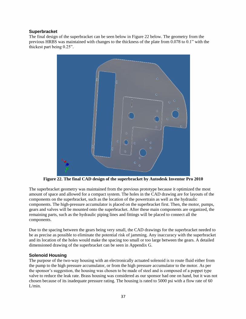
37
Superbracket The final design of the superbracket can be seen below in Figure 22 below. The geometry from the
previous HRBS was maintained with changes to the thickness of the plate from 0.078 to 0.1‖ with the
thickest part being 0.25‖.
Figure 22. The final CAD design of the superbracket by Autodesk Inventor Pro 2010
The superbracket geometry was maintained from the previous prototype because it optimized the most
amount of space and allowed for a compact system. The holes in the CAD drawing are for layouts of the
components on the superbracket, such as the location of the powertrain as well as the hydraulic
components. The high-pressure accumulator is placed on the superbracket first. Then, the motor, pumps,
gears and valves will be mounted onto the superbracket. After these main components are organized, the
remaining parts, such as the hydraulic piping lines and fittings will be placed to connect all the
components.
Due to the spacing between the gears being very small, the CAD drawings for the superbracket needed to
be as precise as possible to eliminate the potential risk of jamming. Any inaccuracy with the superbracket
and its location of the holes would make the spacing too small or too large between the gears. A detailed
dimensioned drawing of the superbracket can be seen in Appendix G.
Solenoid Housing The purpose of the two-way housing with an electronically actuated solenoid is to route fluid either from
the pump to the high pressure accumulator, or from the high pressure accumulator to the motor. As per
the sponsor’s suggestion, the housing was chosen to be made of steel and is composed of a poppet type
valve to reduce the leak rate. Brass housing was considered as our sponsor had one on hand, but it was not
chosen because of its inadequate pressure rating. The housing is rated to 5000 psi with a flow rate of 60
L/min.

38
The solenoid housing is a manufactured part that comes with only one pathway that is either open or
closed as seen in Figure 23a below. Figure D.3 in Appendix G shows a wireframe view of the original
solenoid. In Figure D.4, two more pathways have traditionally been created for previous generations of
the HRBS; one to allow a second flow path from the pump, and another much smaller tap for a pressure
gauge. As seen in Figure 23 below, the final design for this year involves adding yet another pathway.
This pathway is meant to allow pumped hydraulic fluid to flow into the axle and into the theoretical
external high pressure tank. Also, this new pathway is to allow the pressurized fluid in the external tank to
flow back into the axle, to the solenoid housing and to the motor.
A dimensioned drawing of the new solenoid housing can be seen in Figure F.5 in Appendix G.
(a) (b)
Figure 23. (a) Solid view (b) Wireframe view of new prototype solenoid housing in Autodesk
Inventor Pro 2010
Axle One major change with the new HRBS is the design of the axle to allow high-pressure hydraulic fluid into
the axle for it to be stored in a theoretical external high-pressure tank. This design is to allow the HRBS to
be applicable for wheelchairs in future terms. The purpose of re-designing the solenoid housing was to
achieve the customer requirement of being able to measure pressure through the axle. In order to
complete this, the axle needed to be re-designed so that hydraulic fluid can flow from the solenoid
housing, to the axle and to a theoretical external high-pressure tank.
The axle is designed to have a block in the middle with a hole in the block that allows high-pressure fluid
to route from the solenoid housing into the axle. A CAD drawing of this design is on page 39 in Figure
24. The dimensions for the axle were determined with consideration of the superbracket and the
surrounding components. Instead of welding tube-shaped stock to each end of a block, FFP suggested
taking a rectangular stock of steel and turning down each end on a lathe to create a hollowed cylinder and
leaving a block in the middle. The reason for using steel for the axle is because the axle will be supporting
a substantial amount of the bike and rider’s weight. The axle also needs to be able to contain fluid that

39
will pressurize up to 4200 psi. Aluminum was the first choice of material for the axle due to its
lightweight but this material cannot handle large loads. Titanium was recommended to achieve both goals
of lightweight and reliability but due to budget constraints, titanium was not chosen. That is why
ultimately, steel was chosen as the material for the axle.
Figure 24. CAD model of the re-designed axle
User Interface and Controls The user interface consists of two points of interaction: the existing front brake lever and two pushbuttons
mounted on the handlebar. The brake lever will initiate the regenerative braking process by actuating a
toggle switch. This completes the braking circuit and allows the electromagnetic clutch to engage, which
connects the powertrain to the hydraulics. The pushbuttons will activate the hydraulic pressure release
system via the two-way valve to drive the powertrain, propelling the bicycle.
The electromagnetic clutch and valve are on separate power circuits and have fixed electrical
requirements. Both the clutch and valve require 24VDC. This constrains the electric system and forces all
other electrical components to be designed and specified around these parameters. There are several
power options for our user interface, but the use of batteries is the simplest method that we have found.
They are portable and have acceptable energy density for our application.
Figure 25. Circuit diagram to set up the electrical system for the HRBS

40
PROTOTYPE DESCRIPTION The prototype that will be produced by the end of the term will result as being the final design presented
previously in this report. Due to the size of the HRBS being no more than 20 inches in diameter, the final
design is feasible in manufacturing and production. Also since this system has been progressively
developed over several years, a large amount of the designs and analysis have already been conducted.
This saves a lot of time and allows the HRBS to continue being refined and rebuilt for enhanced
functionality. Since previous generations of the HRBS have already been fabricated, a scaled prototype of
the system is unnecessary and, instead, a full size prototype will be manufactured and assembled.
Engineering analysis was executed for the new HRBS with the goal of achieving the engineering
specifications, specified in Table 2 on page 8, in mind. We intend to manufacture the prototype according
to previous HRBS as well as to meet all the design changes that were selected for the new HRBS. Our
prototype will also be manufactured according to the fabrication plan that is discussed in the next section
of this report. A series of validations tests have been devised to test whether the prototype fulfills each of
these specifications. The validation tests are explained in detail further on in this report.
FABRICATION PLAN A variety of parts will need to be modified or machined for the HRBS. A summary of these parts and
processes is listed in Table 16, followed by a more detailed description. All CAD models for these
machined or modified components can be seen in Appendix G. These manufacturing processes are
necessary in order to modify the system to be applicable not only for a bicycle but also for a wheelchair.
Since the system will not fit in a standard bicycle, modifications to the geometry of the bicycle need to be
made. Also, in order to compact the system to fit into the front wheel of a bicycle, not all parts may be
commercially bought. Thus processes for manufacturing and modifying parts are required for prototyping
the HRBS.
Table 16. Summary of manufacturing processes including machines, tools, speed, and location
Component Material Required Machine Speeds Location
Hub bearing
carriers
Aluminum Lathe/Mill 700 rpm GGBrown, UofM
Spokes Aluminum Waterjet Cutter -- ECR
Superbracket 304 Stainless
steel
Water jet cutter -- DOW Building, UofM
Axle Steel Mill; Lathe 600 rpm Federal Fluid Power Inc
Fork Steel tube Mill; Tubing
Notcher; Welder
600 rpm GGBrown, UofM
Gears Reboreable
Steel
Mill; Rotary chuck; 700 rpm
(mill)
GGBrown, UofM
Gears Keyways Steel Broaches; Arbor
press
-- GGBrown, UofM
Gear Shafts Steel Lathe; Mill 950 rpm GGBrown, UofM
Button Carriers 6061
Aluminum
Lathe; Tap 1150 rpm GGBrown, UofM
Electrical System Wires; solder Soldering iron N/A GGBrown, UofM
Clutch Stabilizer
Housing
6061
Aluminum
Lathe; Mill 1150 rpm GGBrown, UofM
Pump/Motor
Stabilizer Collars
6061
Aluminum
Lathe 1150 rpm GGBrown, UofM

41
For some of the machined or modified components, such as the spokes, superbracket, axle, and solenoid
housing, outside assistance is required. Due to the complex, yet two dimensional geometries of the spokes
and the superbracket, these items will be machined using the water jet cutter. The ERC had been
contacted and a machining plan was worked out.
Hydraulics Most of the hydraulic subsystem components are commercially purchased parts, and are the same parts
ordered for previous generations of the HRBS. This guarantees reliability of the components and ensures
compatibility with a hydraulic system. Yet four of the hydraulic components need modifications to work
in the new HRBS: the pump, motor, solenoid housing, and the axle. These modifications are going to be
conducted by FFP since they have professional experience in handling hydraulic components.
The pump and motor currently have M10 port metric fittings and need to be rebored and threaded for
SAE 6 fittings. These SAE 6 fittings are compatible for JIC fittings, which are the most commonly used
fittings for hydraulic systems. Also by modifying the pump and motor, this reduces the total number of
fittings required by the system.
The original solenoid housing comes with two openings but for the HRBS, a total of five openings are
required. Therefore FFP has been requested to modify the two-way solenoid housing to bore three new
holes. Two holes that are ¼‖ diameter will be bored with a national pipe thread (NPT) to allow the
housing to serve as a T-fitting in addition to a two-way valve housing. These holes are necessary to allow
fluid to flow from the pump and to the 1) high-pressure accumulator and 2) the axle. Another hole is a
1/8‖ NPT diagnostic port and is where the pressure gauge will be attached.
Since the solenoid is being modified to allow the pump to send hydraulic fluid to the axle, the axle needs
to be modified as well. The axle will be machined out of an 1‖ x 1‖ x 9‖ steel stock on campus by a
member of this team. Once the geometry of the axle has been machined, a hole will need to be placed in
the block and into the axle. This hole will be bored by FFP and will be ¼‖ diameter with a NPT so that a
JIC-4 fitting can fit into it.
The low-pressure reservoir will be made out of an empty honey bottle, per the same design as the
previous team. The only modification to the low-pressure reservoir will be machining a cap that can
accept a low-pressure hydraulic fitting. This modification will be discussed with FFP.
Powertrain All the gears require machining processes. The main purpose for machining the gears is to reduce the
overall weight of the system since the gears make up a large portion of the HRBS weight. Since the new
HRBS will be a refined version of the old HRBS, the methods for manufacturing the gears will be
followed according to how the Winter ’09 team machined their gears. Listed below is Table 17, which
was provided by the previous team. Their procedure for machining the gears will be replicated exactly for
the new HRBS.
Table 17. Machining processes (and tool) required for each gear
Pump Gear Reduction To Wheel Motor Gear Reduction
G1 1‖ G2 3.5‖ G3 1‖ G4 5‖ G3 1‖ G2 3.5‖ G1 1‖
Bore (lathe) x x x
Keyway (broach) x x x x x
Removal of hub projection (lathe) x x x x x x
Lightening Holes (mill) x x x
Bearing Press-fit (arbor press) x x
42
All of the purchased gears have hub projections that need to be faced off to reduce weight and allow them
to fit within the tight constraints of the system. The lathe and mill machines will be used to accomplish
this task. Those gears that are large enough will also have lightening holes drilled in them to further
reduce the overall weight of the system. This process will be done on the mill. A select few gears will
need to have a larger central hole bored in them so they can fit on a shaft or have a bearing press fit into
them. This will also be done on the lathe. For the aforementioned press fit bearings, an arbor press will be
used.
The mill machine will be used at approximately 700 rpm to face off the hub projections that came with
the original gears. The mill will also be used to drill out some circles in the gears in areas that will be
unused. This procedure will reduce the overall weight of the gears. The lathe machine at approximately
600 rpm will be used to bore some of the gears. This will allow bearings to be pressed into the center of
the gear, using an arbor press, or for the gears to fit onto shafts. Keyways that are 1/8‖ need to be
broached and will be manufactured using an arbor press and on campus.
For each gear, shafts need to be made. The shafts needed for the gears will be made of aluminum. These
will be faced to the correct length and turned down from aluminum stock to the proper diameter using a
lathe at approximately 1150 rpm. Keyways will also be added to several of the shafts as well as retaining
clip grooves so that shaft collars can be attached to them. Details on the location of the keyways can be
seen in the dimensioned CAD drawings in Appendix G. These are necessary to hold the gears in place
when assembled onto the superbracket.
Superbracket A waterjet cutter in the ERC will be used to cut out the geometry and holes in the superbracket. A
waterjet cutter is time efficient, accurate, and will allow for more complexity in the geometry of the
superbracket. Since the superbracket is the foundation of the entire system, a very detailed CAD drawing
of the superbracket has been created and can be seen Appendix G.
Fork Since the HRBS cannot fit into a standard bicycle wheel, a modified fork needs to be fabricated. This will
be done by taking standard steel tubes and welding them onto the ends of the horizontal members of the
current fork on the bicycle. The pieces will first have to be cut to length using the band saw at 600 rpm.
Prior to welding, the bottom of the tubes will be modified to allow for axle placement and attachment.
Then they will be welded together by a teammate that had successfully passed welding training.
User Interface & Controls The push-buttons used for launching the bicycle will be placed at the end of each handlebar on the
bicycle. They will be mounted in button carriers that will be made from 6061 aluminum. The lathe at
approximately 1150 rpm will be used to turn and drill the button carriers and then will be pressed into the
ends of the handlebar using an arbor press.
The controls for the HRBS require an electric system to be wired. This electrical system wiring will be
contained inside the handlebar, run into and through the axle on the non-fluid flow side and then connect
to the HRBS. The ends of the wire will be soldered to their respective components. The wires will not be
tight and will be loosely routed through the handlebar and into the axle to allow for less strain, less
damage, and a longer lifetime. Plastic tubing will surround the wires between the parts they’re exposed
(from the handlebar to the axle) in order to reduce safety for the user riding the bike. Doing this will also
contain the wires and help prevent wear and any tangling from occurring.
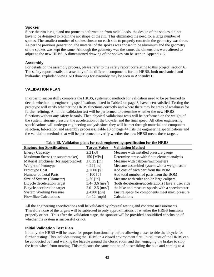
43
Spokes Since the rim is rigid and not prone to deformation from radial loads, the design of the spokes did not
have to be designed to retain the arc shape of the rim. This eliminated the need for a large number of
spokes. The smallest number of spokes chosen on each side to properly constrain the geometry was three.
As per the previous generation, the material of the spokes was chosen to be aluminum and the geometry
of the spokes was kept the same. Although the geometry was the same, the dimensions were altered to
adjust to the new HRBS. A dimensioned drawing of the spokes can be seen in Appendix G.
Assembly For details on the assembly process, please refer to the safety report correlating to this project, section 6.
The safety report details the assembly of the different components for the HRBS, both mechanical and
hydraulic. Exploded view CAD drawings for assembly may be seen in Appendix H. VALIDATION PLAN In order to successfully complete the HRBS, systematic methods for validation need to be performed to
decide whether the engineering specifications, listed in Table 2 on page 8, have been satisfied. Testing the
prototype will verify whether the HRBS functions correctly and where there may be areas of weakness for
further refining. An initial validation test will be performed to determine whether the new HRBS
functions without any safety hazards. Then physical validations tests will be performed on the weight of
the system, storage pressure, the acceleration of the bicycle, and the final speed. All other engineering
specifications will undergo engineering analysis since they will be met through material and component
selection, fabrication and assembly processes. Table 18 on page 44 lists the engineering specifications and
the validation methods that will be performed to verify whether the new HRBS meets these targets.
Table 18. Validation plans for each engineering specification for the HRBS
Engineering Specifications Target Value Validation Method
Energy Capacity 2.2 [kJ] Measure with installed pressure gauge
Maximum Stress (on superbracket) 150 [MPa] Determine stress with finite element analysis
Material Thickness (for superbracket) ≤ 0.25 [in] Measure with calipers/micrometers
Weight of Prototype < 24 [lbs] Measure assembled system with a weight scale
Prototype Cost ≤ 2000 [$] Add cost of each part from the BOM
Number of Total Parts < 100 [#] Add total number of parts from the BOM
Size of System (Diameter) ≤ 20 [in] Measure with ruler and/or large calipers
Bicycle deceleration target 3.4– 3.6 [m/s2] (both deceleration/acceleration) Have a user ride
the bike and measure speeds with a speedometer Bicycle acceleration target 2.0– 2.5 [m/s2]
System Working Pressure ≤ 4200 [psi] Ensure specs for components meet max. pressure
Flow Size Calculations for 12 [mph] Calculations
All the engineering specifications will be validated by physical testing and concrete measurements.
Therefore none of the targets will be subjected to only approximations of whether the HRBS functions
properly or not. Thus after the validation stage, the sponsor will be provided a solidified conclusion of
whether the system is successful or not.
Initial Validation Test Plan Initially, the HRBS will be tested for proper functionality before allowing a user to ride the bicycle for
further testing. This includes testing the HRBS in a closed environment first. Initial tests of the HRBS can
be conducted by hand walking the bicycle around the closed room and then engaging the brakes to stop
the front wheel from moving. This replicates the same motion of a user riding the bike and coming to a

44
slow stop. The initial validation test is not meant to test the system fully, since the required load will not
be placed on the bicycle at this time. This hand walking test will allow for a closer analysis of the
different gears and components of the HRBS since the system will be moving slowly. Evaluation of the
different seals in the system will also be conducted to make sure no leaks exist in the system. If testing
during this stage displays a dysfunction of any parts of the HRBS, amends to the system will be made
before proceeding with further tests.
Once these are determined and the subsystems are functioning properly, a user will position them self on
the seat of the bike, allowing their weight to be added onto the HRBS. Walking the bicycle around slowly
with the additional weight of the user will allow observations of whether the system continues to function
properly under heavy load. If the gears continue to function correctly under the load, further testing may
begin and it may be conclude that the engineering specification of maximum stress has been met. If not,
further modifications and FEA analysis of the HRBS will be conducted before proceeding.
If all the subsystems functions safely, the simpler validation tests listed in Table 18 can be performed
during this stage. These include the tests to verify the engineering specifications of material thickness,
weight of the prototype, determining overall prototype cost, total number of parts, and measuring the size
of the system.
Physical Validation Test Plan Once the system appears to be functioning, the system will be taken outside for more specific testing. A
user will ride the bicycle and pedal the uncharged HRBS up to different initial bike speeds. The
acceleration of the bicycle will be measured with a retrofit speedometer to verify that the engineering
specification for acceleration is met. The user will then engage the brakes on the bicycle, causing the
system to stop and storing the hydraulic fluid in the high-pressure accumulator. This stored pressure will
be measured by the built-in pressure gauge. In the launching phase, the HRBS will be activated by the
user to bring the bike up to a final speed. Both the acceleration of the bicycle and the final speed will be
measured using the speedometer and then compared with the engineering targets.
Safety for Validation Testing Safety precautions that will be followed are discussed in detail in the safety report for the HRBS. Safety
measures include testing in an area clear of pedestrians, modifying the hydraulic components only by
following measures outlined by Parker Hannifin Corporation’s safety procedures, and having both the
observer and bicycle rider wear protective gear.
Validation Testing Outcome In Design Review Four, it was estimated that the prototype would be completed and tested a few days
prior to the design expo. Due to some unforeseen incidents, the prototype was not completed in time to
completely validate the design. Plans of future testing with this current HRBS are also unfortunately not
possible due to some design oversights.
As mentioned in the Fabrication plan, the motor and pump were brought to FFP to be re-threaded for SAE
6 fittings. When brought to FFP, they informed the team that they had fittings that would fit the current
metric fittings the pump and motor came with. Therefore to save us machining costs, they would just
provide us with the proper size fittings rather than re-machine the pump and motor. The team did not see
a problem with this, and went ahead with keeping the original pump and motor metric threads.
After the manufacturing and assembly of the superbracket was completed, all the mechanical components
were placed on the superbracket. The entire assembly then had to be taken to FFP for the assembly of the
hydraulic components, as advised by the previous year’s team. After taking it to FFP, the professionals at
FFP realized that the fittings for the metric threaded pump and motor were too large for our system, and

45
would not fit within the constraints of the diameter of the superbracket. Therefore they needed to machine
the pump and motor for SAE 6 threads to be able to use smaller fittings. Since FFP wasn’t planning on re-
machining the pump and motor, they did not have the correct threads in stock for the SAE 6 threads.
Therefore they said they would not be able to complete the hydraulic installation that same day since they
did not have all the proper pieces in stock. This was on a Friday.
They requested to leave the system over the weekend so they could complete the assembly by the
following Tuesday. They needed the system Friday to figure out which parts they needed to order, then
they would use Monday to order the parts and expect delivery on Tuesday. This was not a part of the
project plan, as it was noted by the previous team that this process should only take a couple of hours.
This misunderstanding was caused because it was not noted that FFP had provided a hydraulic component
layout to the previous team around which the superbracket was designed. Since the same design of the
superbracket was used this year with small changes, FFP could not accommodate the same set of
components in a similar arrangement around the design changes. This was also because tightening the
hydraulic components is always going to be different; so the hydraulic system from the previous
generation would not necessarily be the same size as the hydraulic system as the new hydraulic system.
Therefore configuring the hydraulic system first, before the superbracket and mechanical components
needs to be taken into account for future terms.
On 04/13/2010, FFP could not assemble the hydraulic components on the superbracket; instead they
provided separate fittings which had to be assembled and sealed by the team. This was also unexpected,
as FFP had provided a completely assumed hydraulic system to the previous team. The installations of all
the hydraulic components in the compact system was a major, and unanticipated, challenge because issues
such as incorrect amount of tightening and loosening of fittings can cause pre-determined locations of
components to change or cause leaks. After several attempts, all components were fit and sealed together
with a minor change to the location of the motor. This move was accomplished by expanding the original
motor shaft hole and drilling new mounting holes on the superbracket.
The day that was taken to assemble the hydraulic system and re-design the superbracket was originally
allocated for the final assembly of the HRBS on to the bike. Yet the assembled superbracket with all the
hydraulic fittings had to be taken back to FFP on Wednesday 4/14/2010 for the installation of a hard line
that would complete the hydraulic circuit. The reason this needed to be done separately from receiving the
hydraulic components before is because FFP needed the hydraulic system assembled first, before they
could implement the hard line.
After receiving the final assembly from FFP, most of Wednesday was spent assembling the superbracket
onto the axle, the fork and then onto the bike. This process also took more time that expected due to some
alignment issues that are common with components that are not professionally machined. For example,
although the spokes were designed to clear all the components while rotating, they failed to do so during
assembly. This might be due to the fact that the wheel could not be installed in a straight position due to
inaccurate welding of the fork which also caused a slight misalignment of the superbracket relative to the
wheel. Another example is that the axle was machined on campus and in the machine shop. The machines
in the shop, such as the lathes, are very old and very difficult to re-calibrate. Machining the axle was
difficult because when lathing down the cylindrical part, the diameter of the axle would taper and thus be
unsymmetrical. Bob Coury, the machine shop supervisor, advised that it was probably because the
machines were old and not precisely calibrated. An uneven axle meant the superbracket would not sit on
the axle straight. The superbracket not sitting on the axle straight, as well as the axle being unsymmetric,
caused it difficult to mount with the forks. Overall, this did not give the team a chance to test the system
before the design expo on 4/15/2010.

46
After consulting the sponsor, David Swain at the Design Expo, the team was notified of some mistakes
made in the design which will make the prototype impossible to test in the future. One of the design
errors was overlooking the pump and motor stabilizers. The team failed to understand the purpose and
importance of the stabilizers and decided not to make them and imagined that the gear shafts would
suffice. The sponsor explained that without the stabilizers to hold the pump and motor shafts in place, the
pump and motor gears will try to shear away from the 3.5‖ gears when the hydraulics are in operation. He
explained that if hydraulic oil is put into the system and tested, the force on the pump and motor shafts
will cause them to fail, damaging the pump and motor. The sponsor also explained the downside of using
pipe fittings and sealants in hydraulic systems. He explained that without careful installation, pipe fittings
almost always leak and the sealant that has to be used in pipe fittings is not good for hydraulic systems. If
the sealant is put too far down the thread of the fitting, the material would enter the hydraulic fluid and
damage fragile components. Since the team put together the pipe fittings with sealants and it was not
professionally done, we expect that this might be an issue as well.
Due to these issues, detailed recommendations to fix these problems have been addressed in the
recommendations section later on in this report.
The validation tests that were able to be completed are listed in the table below. The engineering
specifications that were not able to be verified physically (but were verified analytically) include the
maximum stress on the superbracket, the energy capacity of the system, and the acceleration/deceleration
targets for the HRBS.
Table 19. Validation plans for each engineering specification for the HRBS
Engineering Specifications Target Value Validation Result
Material Thickness (for superbracket) ≤ 0.25 [in] Thin part: 0.1‖ / Thickest part: 0.25‖
Weight of Prototype < 24 [lbs] 30 lbs
Prototype Cost ≤ 2000 [$] $1500
Number of Total Parts < 100 [#] 96
Size of System (Diameter) ≤ 20 [in] 14‖
PROJECT PLAN The following section describes the project plan for achieving the task the EPA would like to achieve.
This plan has been developed to guide the project smoothly and maintain appropriate deadlines. This plan
is divided into five phases that begin and end with major project milestones. For a more complete
breakdown of this project timeline, see the Gantt Chart in Appendix E.
Phase I: Initial Research The first step in commencing this project was becoming acquainted with the sponsor, Mr. David Swain
from the EPA. He provided plenty of background information and insight into the current proposal of the
project, the goals and customer requirements, and challenges that may arise. From multiple discussions
with Mr. Swain, the engineering specifications were produced for the customer requirements. For further
analysis of the project, background research on hydraulic systems, electric systems, and current market
products was conducted. A QFD was created to correlate the customer requirements, engineering
specifications and benchmarks, and can be found in Appendix D. To proactively plan for accomplishing
this project, the Gantt Chart in Appendix E was created during this stage. This phase of the project was
concluded with Design Review (DR) 1.
47
Phase II: Initial Designs After DR1, the second phase of the project began. In this phase, further research on previous HRBS and
prototypes will be performed. This is necessary to determine problems previous teams have encountered
with the HRBS and to define the main functions. Once the main functions are developed, the engineering
requirements and customer specifications will be considered in order to draw up preliminary concepts for
each function. These preliminary concepts will not only attempt to address the customer specifications,
but also focus on the failures encountered in previous prototypes. After generating these concepts, an
evaluation and selection of the best concepts will be conducted. After evaluating each concept
systematically, final concepts for each function will be selected and implemented in CAD. These will be
the Alpha Designs. This phase will end with DR2.
Phase III: Design Selection After DR2, the Alpha Designs selected from Phase II were refined and developed further.
A non-operational previous prototype will be brought to the University of Michigan for disassembly. This
will help in further understanding of the HRBS and the subsystem functions.
Most parts needed for the final design will be ordered during this stage. Once the final design is
established and after disassembling the old HRBS, prototype production will begin on any parts or
assemblies that are available at the time. This phase ends with DR3.
Phase IV: Prototype Production After DR3, production of the prototype will be in full swing. The components for the HRBS that need to
be manufactured or modified on campus should be completed during this stage. The HRBS should be
brought to Federal Fluid Power (FFP) for hydraulic fittings and tubings and assembly of the hydraulic
system. While FFP has the system, the mechanical components (i.e gears, axle, superbracket) should be
completely manufactured by the end of this stage. This stage ends with DR4.
Phase V: Prototype Testing and Project Completion After the hydraulic system is fully assembled, the system’s mechanical components will be assembled
and mounted onto the superbracket. Once the HRBS is finalized with both the hydraulic and mechanical
system, the entire HRBS will be mounted onto the axle and then implemented in the bicycle for a
complete prototype. Validation testing of the prototype should commence during this phase. Should any
redesigns or reconstructions be necessary to present a safe, working prototype at the Design Expo, they
will happen at this time. This phase, and the project as a whole, concludes with the Design Expo on April
15th, 2010.
DISCUSSION
As in all things designed and implemented in a three-month span, the design had its fair share of flaws.
Critiques have been made on machining and manufacturing on campus, assembly, and working with
outside sources. At the end, the biggest problem was trying to assemble a bunch of parts that were made
by the group and therefore weren’t entirely perfect. The two major design changes for this year, the
superbracket and the axle, both would have performed their required tasks without problem had the rest of
the system been operational.
Machining and Manufacturing As mentioned in the validation outcome section on page 45, the axle was machined on campus and in the
machine shop. Machining the axle was difficult because when lathing down the cylindrical part, the
diameter of the axle would taper and thus be unsymmetrical on both ends. Bob Coury advised that it was
probably because the machines were old and not precisely calibrated. An uneven axle meant the

48
superbracket would not sit on the axle straight, not align with the fork properly and then not position
inside the wheel accurately.
The fork was another student machined component. The fork required steel stock to be cut into 4 pieces: 2
longer legs, and 2 shorter legs. One long leg would need to be welded onto one short leg to create an L-
shape. The fork legs needed to be positioned in an angle, making it very difficult to position them
stationary when attempting to weld. Since the legs could not be set flat on the table, situating them to
align with each other, without moving while trying to weld was very challenging. This caused slight
misalignment issues between the legs. This same problem arose when the L-shaped legs needed to be
welded onto the main shaft on the bike (that connects to the handlebars). The L-shaped legs could not be
positioned flat on the table, making it hard to position accurately (without moving when trying to weld)
and thus resulting in slight misalignment.
Assembly In the design, the packaging was extremely tight and, therefore, the margin for error was miniscule. This
tight packaging was both strength and a weakness. The fact that everything was able to fit within the
confines of the front wheel of a kid’s bike was a true achievement of design by this team and the one
before it.
The weakness was designing something requiring a level of precision that the team could not duplicate
given their general novice machining ability, the tools, and facilities available. Due to problems with
student machining or the facilities available, problems in assembly would arise due to misalignment and
flaws of the manufactured components. There may have been other issues with gears meshing or
difficulties with the hydraulics, but it is believed that these issues are made all the more unmanageable by
the tight confines the system was restricted to. It is believed, especially if prototyping on a wheelchair that
moving the system out-of-hub would alleviate many clearances and packaging issues that cause the level
of complexity of the current systems to be so high.
Working with Outside Sources Please read the Validation Outcome section on page 45.
RECOMMENDATIONS
Throughout the course of the semester our team compiled a list of recommendations for future projects
related to ours. This section of the report outlines these recommendations.
CAD Modeling While having the extensive database of CAD models from previous teams was very useful at the
beginning of the semester, the fact that we put so little of the system into CAD ourselves became a
hindrance during production. Only by making your own CAD models can you guarantee accuracy and
gain the intimate knowledge of the system required when fabricating such a complex and highly precise
group of components.
Pump/Motor For two years in a row now, FFP has had to modify the pump and motor to work in the system. A
different pump and motor, perhaps with non-metric fittings, may be more appropriate. However, if the
sponsor provides the pump and motor, and already has a number of these Marzocchi units, it would be
better to design around them than to waste money. If these pumps are used again, be sure to constrain the
output shafts/gears so as to not allow them to be pushed in any direction by the gear they are meshing
with. The pump and motor are apparently rather sensitive to lateral forces on the output shafts and can

49
easy be irreparably damaged in this manner. In our design, the gears meshing with the pump and motor
gears are also raised 0.15 inches due to the extra thickness of the superbracket in these areas. This would
call for a lengthened output shaft on the pump and motor to allow for proper meshing between these
gears, a detail our team failed to see.
Working with Professionals Professional assistance is most definitely required when working on a project like this. If the next project
remains an in-wheel design, there isn’t a lot of flexibility. Still, experts, such as Federal Fluid Power,
should be contacted prior to finalizing a design. For example, they recommended having the hydraulic
system all sized and placed by them before mounting holes are drilled in any future superbracket. At this
point, the mechanical system (gears and so forth) can be moved around to fit the assembled placement of
the pump and motor. When our hydraulic system was all tightened down, the pump was significantly out
of line with its mounting holes. New holes had to be drilled and the main gear hole had to be enlarged.
We were fortunate that the gears still meshed, but this was only due to a lucky coincidence and this
situation should be taken into account in the future.
Another problem we faced that could have used professional assistance was welding our fork. None of the
members of this team were experienced welders and the fork was fairly poorly constructed as a result.
The forward angle of the two forks from the main vertical that attaches to the bike was particularly
difficult to reproduce because the two pieces being welded could not simply be placed on a flat surface.
While this angle is not a structurally important detail, it sure looked strange. We lost about one inch of
width between the two uprights of the fork due to poor welding and this caused a host of clearance issues.
Professionals, perhaps a bike shop such as Great Lakes Cycling and Fitness or simply an experienced
welder, should be contacted for help with this issue.
Avoiding Pipe Threading As our sponsor, Dave Swain, told us many times, and as we’re sure he’ll tell future teams many times, do
whatever you can do avoid pipe threads in your hydraulic components. These fittings basically rely on
tightening and crushing the threads a little bit to create a seal. If you ever loosen a fitting, it has to be
tightened past the point it was last tightened to to create a new seal. This means that if you had something
tightened to just the right angle but you had to disassemble the system for some reason, you would have
to tighten it a full rotation beyond where it was to return to that perfect angle. Eventually, you will run out
of threads. Pipe threads also require pipe dope that, if it goes beyond the threads and gets into the
hydraulic lines, can contaminate the system and cause the valves to jam. SAE and JIC fittings are re-
sealable and do not require pipe dope. Make sure you stress this point to FFP, or whoever your hydraulic
experts are. They will know all about the merits of one vs. the other, but let them know that you don’t
want to deal with pipe threads. We did not sufficiently stress this point and every hole they tapped for us
was done with pipe threads.
Scheduling The greatest recommendation we can offer is an echo of one point made by the 2009 team. For a project
of this complexity to be completed in one semester, the team must have an aggressive sourcing and
manufacturing schedule. Some hydraulic parts have very long lead times (> 2 months) and need to be
ordered within a couple weeks of forming the team, and manufacturing needs to begin well before other
teams. This means the safety report will need to be completed well ahead of the norm for the class. If
large-scale manufacturing hasn’t begun by the beginning of March, you’ve fallen behind.
Out-of-Hub Possibilities Despite the fact that it would be cool for the system to be modular and therefore work on a bike or a
wheelchair, we don’t see the reason for it. The in-hub design makes sense on a bike, but there is so much
more space for mounting things on a wheelchair. Not being constrained to such a small space would be a

50
huge advantage that would help avoid most, if not all, of the clearance and assembly issues this team
faced in the final push to complete the prototype. It would also do away with the need to rebuild the
wheel itself (with custom spokes and a BMX bike rim), which can be an arduous task. Going out-of-hub
would also provide a new and unique design challenge for a team that can’t be matched by yet another
iteration of the in-hub concept.
Another Possibility One random thought, too late into the semester to act on it, about how to fix the issue of gears jamming or
pulling away from each other was to investigate using timing belts and pulleys instead of gears. We
haven’t done any research into the viability of this option, but the flexibility of the belts could help negate
any gear meshing related problems.
CONCLUSIONS The goal of this project is to prototype a fully functional kid’s bicycle with a hydraulic regenerative
breaking system (HRBS) contained in the front wheel while also making the system wheelchair
applicable. Using a HRBS is more energy efficient than electric powered vehicles and making the HRBS
applicable for wheelchairs will help wheelchair users control their speed on hill decent and apply an assist
during hill climb. However before implementing the HRBS in a wheelchair, the system needs to work on
a bicycle; a problem many previous teams have encountered. Thus, the main objectives for this project are
to prototype a functional bicycle with a HRBS with the design to be applicable for wheelchairs as well.
The most important customer requirements are to be able to measure the pressure through the axle,
increase the rigidity of the superbracket and keep the weight of the system at a minimum. The most
significant engineering specifications are the energy capacity of the system, determining the maximum
stress applied to the superbracket, and the weight of the system. The target values for the maximum stress
on the superbracket and energy capacity of the system will be calculated once the final design stage
begins. The goal for the weight of the system is 20 lbs or less.
Various sub-systems required of the project were determined and organized into main functions of this
project: (1) measuring the pressure through the axle, (2) the stiffness of the superbracket, (3) the method
of releasing the energy for the user, and (4) preventing leakage of the hydraulic fluid in the system.
Literature search and engineering specifications were taken into account when designing preliminary
concepts for each main function. A morphological chart was used to gather the best preliminary concepts
for each function. A Pugh chart was then used to systematically rate the strengths and weaknesses of each
design according to the customer requirements. From the scores of the Pugh chart and further
consideration of the highest ranked concepts, it was determined that for measuring the pressure through
the axle, the boring of an extra flow path in the solenoid housing would be optimal. A combination of
multiple concepts that consisted of thickening the material and cutting away unused space would be the
best concept for the superbracket. Since safety is paramount over convenience, two buttons will be
implemented into the system to release the stored energy in the system. JIC and O-ring fittings will be
used to prevent leakage of the hydraulic fluid in the HRBS.
After selecting the alpha design, engineering design parameter analysis was conducted on the entire
HRBS. This includes FEA, CAD modeling and FMEA analysis for each of the components within the
subsystems in the HRBS. Analysis was conducted on individual functions such as the gear transmission,
the overall bike, and the hydraulic and mechanical system. This helped in finalizing the selected designs
and verified that the components would be compatible with the new prototype. After analysis was
conducted on the entire system, the final designs were solidified. The main designs included the re-design
of the axle, superbracket, solenoid housing, and then using the same powertrain as previous generations of
the HRBS. After the final designs were made, a fabrication plan was established. Most parts of the HRBS

51
are commercially purchased components while eight total parts of the system needed to be modified or
machined. After the fabrication of the system, a prototype was fully assembled.
The fully assembled HRBS had a relatively low weight and a high level of safety and functionality while
being more robust and wheelchair applicable. Some issues with outside sources caused the assembly and
validation timeline to become too compact to be completed before the end of the semester. As a result, the
HRBS was not completely tested and physically validated due to time limitations as well as recently
informed restrictions on the provided pump and motor shafts. The engineering specifications of weight,
superbracket thickness, size of system, total number of parts, prototype cost, and system working pressure
were able to be achieved through physical validation. The engineering specifications that could not be
physically validated were the maximum stress on the superbracket, and bicycle acceleration/deceleration
targets. Yet the two major customer requirements: (1) route high-pressure fluid into the axle and (2)
increase the rigidity of the superbracket, were completed and through engineering analysis, it is believed
that these parts would have performed their required tasks without flaw.
A full assembled prototype was presented at the University of Michigan’s Design Expo on April 15th,
2010. ACKNOWLEDGEMENTS Our team would like to thank all those people and organizations who provided supportive input and made
this project a success: David Swain, Professor Katsuo Kurabayashi, Engineering Resource Center,
Federal Fluid Power, Bob Coury, Marvin Cressey, ME 450 Winter 2009 Team 24, Jason Moore, Parker
Hannifin Corporation, AutoLab Machine Shop, and the City of Ann Arbor Planning and Development
Services.
REFERENCES [1] Annual Energy Review. (2009, June 26). U.s. energy information administration independent
statistics and analysis. Retrieved from http://www.eia.doe.gov/emeu/aer/
[2] Permo-Drive. (n.d.). Hybrid comparisons. Retrieved from http://www.permo-
drive.com/compare/index.htm
[3] Hybrid Battery Toxicity. (2006, April 8). Retrieved from http://www.hybridcars.com/battery-
toxicity.html
[4] Eaton. (2006, August 14). EPA showcase new fuel-saving hydraulic hybrid UPS delivery vehicle that
will be road-tested in Cleveland. Retrieved from http://www1.eaton.com/epa/index.html
[5] Hydrogen fuel cell bicycles. (2007, September 11). Retrieved from http://www.alternative-energy-
news.info/hydrogen-fuel-cell-bikes/
[6] Pronto m51 with surestep. (n.d.). Retrieved from http://www.invacare.com/cgi-
bin/imhqprd/inv_catalog/prod_cat_detail.jsp?s=0&prodID=M51P&catOID=-536887467
[7] Mierendorf, M., Murphee, A., Rogers, B., & Simmons, S. (2008). Hydraulic Regenerative Braking for
a 20” Bicycle Wheel. ME450 Winter 2008.

52
[8] Alanen, N., Dykstra, J., Muccioli, J., & Yousuf, J. (2008). Hydraulic Regenerative Braking for a 20”
Bicycle Wheel. ME450 Fall 2008.
[9] Fittings & couplings. (2009). Hydraulics & Pneumatics, Retrieved from
http://www.hydraulicspneumatics.com/200/TechZone/FittingsCouplin/Article/False/9470/TechZone-
FittingsCouplin
[10] B. D’Souza, A. Kneifel, V. Singh, M. Williams. (2009) Design Review 2: Optimizing a Hydraulic
Regenerative Braking System for a 20‖ Bicycle Wheel. The University of Michigan.
[11] Marzocchi Pompe (2006). High Pressure Gear Pumps.

APPENDICES
Appendix A – Bill of Materials
Table A.1. Bill of Materials for purchased parts and stock for fabricating the HRBS Part Name / Description Part Number Quantity Vendor Manufacturer Total Price
5” Gear 16DP S1680 1 Applied Industrial
Tech
Martin $57.46
3.5” Gear 20DP S2070 2 Applied Industrial
Tech
Martin $81.86
1” Gear 16DP S1616bs1/2 2 Applied Industrial
Tech
Martin $47.16
1” Gear 20 DP S2020bs1/2 2 Applied Industrial
Tech
Martin $47.20
Applied Industrial Tech Shipping
+ tax
$41.65
MOSFET STP16NK60Z 3 Digikey $6.99
Female Crimp Connector WM18235-ND 10 Digikey $2.70
9 Volt Battery Snap BS12I-HD-24AWG-ND 4 Digikey $1.32
Voltage Regulator 24V 2A 497-1470-5-ND 1 Digikey $0.68
Voltage Regulator 24V 1.5A 497-1458-5-ND 1 Digikey $0.68
Toggle Switch 360-1902-ND 1 Digikey $5.85
Push Buttons EG1932-ND 2 Digikey $7.54
Fuse 0.5 A 507-1011-ND 4 Digikey $2.68
Fuse 1.5 A 507-1014-ND 4 Digikey $2.68
Key Lock CKC8018-ND 1 Digikey $5.43
Digikey Shipping + Tax $14.38
Housing SBV11-8V-CM-S6T-24BQP-00 2 RHM fluid Power Eaton Vickers $ 98.08
Solenoid SBV11-8V-CM-S6T-24BQP-00 1 RHM fluid Power Eaton Vickers $ 56.94
24 volt Vickers coil MCSCP024DQ000010 1 RHM fluid Power Eaton Vickers $ 7.86
RHM shipping + tax ND

9V alkaline batteries 71455K56 4 McMaster Carr $10.76
24 Amp wire 8073k617 25’ McMaster Carr $1.72
Female Crimp Connecter 7060k58 1 McMaster Carr $ 2.68
Pressure Gauge 9767T217 1 McMaster Carr $9.80
Thrust Bearing (0.5” ID) 5909k31 1 McMaster Carr $2.66
Thrust Bearing Washer (0.5” ID) 5909k44 1 McMaster Carr $0.90
Thrust Bearing (0.75” ID) 5909k33 1 McMaster Carr $2.73
Thrust Bearing Washer (0.75”
ID)
5909k46 1 McMaster Carr $1.00
Flange mounted needle bearing 1434k6 1 McMaster Carr $ 9.86
0.375” ID Ball Bearing 60355k45 2 McMaster Carr $10.20
0.5” ID Ball Bearing 6384k61 1 McMaster Carr $6.90
Keystock 0.1875” 98535a140 1 McMaster Carr $2.74
Shaft collar 6mm ID 57485k66 3 McMaster Carr $4.05
Shaft Collar 6157k16 1 McMaster Carr $3.02
Shaft Collar 9677t1 2 McMaster Carr $14.86
McMaster Carr Shipping +Tax $9.00
Filter SS-4FW4-2 1 Swagelok $85.60
Relief Valve ss-4r3a5 1 Swagelok $137.30
Spring kit for relief valve 177-r3a-k1-g 1 Swagelok $3.90
Check Valve ss-chm4-1 1 Swagelok $51.20
Swagelok Shipping + Tax $7.87
Children’s Bike 20” wheel NA 1 Craigslist $50.00
Wheel Rim
20” double wall
NA 1 Ebay Alex $ 21.00
Shipping for Wheel Rim $9.00
Work on Solenoid and Axle Work on Solenoid and Axle sevice Federal Fluid
Power
$108.73
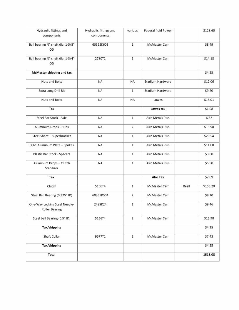
Hydraulic fittings and
components
Hydraulic fittings and
components
various Federal fluid Power $123.60
Ball bearing ¾” shaft dia, 1-5/8”
OD
60355K603 1 McMaster Carr $8.49
Ball bearing ¾” shaft dia, 1-3/4”
OD
2780T2 1 McMaster Carr $14.18
McMaster shipping and tax $4.25
Nuts and Bolts NA NA Stadium Hardware $12.06
Extra Long Drill Bit NA 1 Stadium Hardware $9.20
Nuts and Bolts NA NA Lowes $18.01
Tax Lowes tax $1.08
Steel Bar Stock - Axle NA 1 Alro Metals Plus 6.32
Aluminum Drops - Hubs NA 2 Alro Metals Plus $13.98
Steel Sheet – Superbracket NA 1 Alro Metals Plus $20.54
6061 Aluminum Plate – Spokes NA 1 Alro Metals Plus $11.00
Plastic Bar Stock - Spacers NA 1 Alro Metals Plus $3.60
Aluminum Drops – Clutch
Stabilizer
NA 1 Alro Metals Plus $5.50
Tax Alro Tax $2.09
Clutch 5156T4 1 McMaster Carr Reell $153.20
Steel Ball Bearing (0.375” ID) 60355K504 2 McMaster Carr $9.10
One-Way Locking Steel Needle-
Roller Bearing
2489K24 1 McMaster Carr $9.46
Steel ball Bearing (0.5” ID) 5156T4 2 McMaster Carr $16.98
Tax/shipping $4.25
Shaft Collar 9677T1 1 McMaster Carr $7.43
Tax/shipping $4.25
Total 1515.08
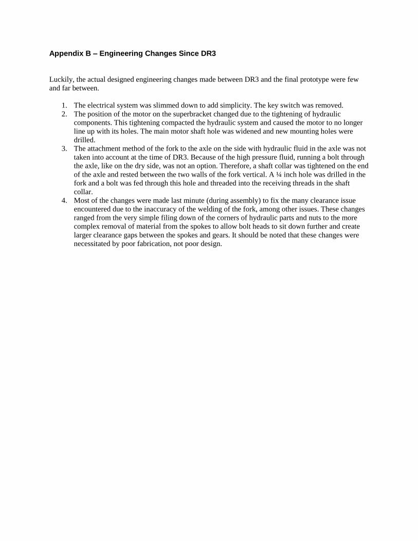
Appendix B – Engineering Changes Since DR3 Luckily, the actual designed engineering changes made between DR3 and the final prototype were few
and far between.
1. The electrical system was slimmed down to add simplicity. The key switch was removed.
2. The position of the motor on the superbracket changed due to the tightening of hydraulic
components. This tightening compacted the hydraulic system and caused the motor to no longer
line up with its holes. The main motor shaft hole was widened and new mounting holes were
drilled.
3. The attachment method of the fork to the axle on the side with hydraulic fluid in the axle was not
taken into account at the time of DR3. Because of the high pressure fluid, running a bolt through
the axle, like on the dry side, was not an option. Therefore, a shaft collar was tightened on the end
of the axle and rested between the two walls of the fork vertical. A ¼ inch hole was drilled in the
fork and a bolt was fed through this hole and threaded into the receiving threads in the shaft
collar.
4. Most of the changes were made last minute (during assembly) to fix the many clearance issue
encountered due to the inaccuracy of the welding of the fork, among other issues. These changes
ranged from the very simple filing down of the corners of hydraulic parts and nuts to the more
complex removal of material from the spokes to allow bolt heads to sit down further and create
larger clearance gaps between the spokes and gears. It should be noted that these changes were
necessitated by poor fabrication, not poor design.

Appendix C – Extra Assignments
1. Material Selection (Functional Performance)
Component 1: Superbracket
Function: The superbracket acts as a mounting plate for all in-hub components of the HRBS.
Objective: The superbracket must not only serve as a mounting plate, it must also remain rigid under any
stresses and torques applied by the motor, pump, and gear train.
Constraints: Space and cost are the only constraints. It must be strong enough while fitting inside the front
wheel of the kid’s bike and fitting within our budget.
Material Indices: Yield Strength > 55 ksi
Cost < $20 for full superbracket
Weight < 4lbs for full superbracket
Top Five Choices:
Carbon Steel AISI 1022
Stainless Steel AISI 304
Aluminum 7075 T6
Titanium, alpha-beta alloy, Ti-6Al-4V, annealed, generic
Magnesium alloy, EA55RS, wrought
Final Choice:
Carbon Steel was chosen as the material for the superbracket. Its combination of high strength,
low cost, and immediate availability outweighed the weight penalty of this choice over the costlier
options (aluminum, stainless, magnesium, and titanium). This material was used in our final design. The
cost of the raw material was less than $10 and the final weight is 3.1 lbs.
Component 2: Axle
Function: The axle has four functions. It is what the wheel spins around, it transfers the weight of the
rider to the wheel, it holds high pressure fluid inside, and it provides the rigid attachment between the
superbracket and the bike.
Objective: Withstand loads of the rider, torques from the superbracket, and internal pressure.
Constraints: Only constraints are cost and weight.
Material Indices: Yield Strength >
Cost < $10
Weight < 2lbs
Top Five Choices:
Carbon Steel AISI 1022
Stainless Steel AISI 304
Aluminum 7075 T6
Titanium, alpha-beta alloy, Ti-6Al-4V, annealed, generic
Magnesium alloy, EA55RS, wrought
Final Choice:
For the same reasons as with the superbracket, carbon steel was chosen as the material for the axle. The
cost of the material was $3 and the final weight of the part is 3 lbs.

2. Design for Environmental Sustainability
The low carbon steel, AISI 1022, as rolled, is the raw material we used to manufacture the superbracket
and axle. And we used aluminum 7075 T6 to manufacture the spokes.
The production of the carbon steel and Aluminum has an impact on the environment, including the
carbon dioxide emission, water use and energy dissipation.
Low Carbon Steel, AISI 1022, as rolled Aluminum 7075 T6
Mass needed in final design 5.90kg 1.81kg
Composition& Weight Percentage C(carbon) 0.17-0.23% Al(aluminum) 89-92%
Fe(iron) 98.7-99.1% Cr(chromium) 0-1.6%
Mn(manganese) 0.7-1% Cu(copper) 0-0.16%
P(phosphorus) 0-0.04% Mg(magnesium) 2.5%
S(sulfur) 0-0.05% Zn(zinc) 5.6%
Air emission 316.47g 88.76g
Water emission 258.24g 1.61g
Raw material 2169.93g 759.16g
Solid waste 658.70g 467.08g
Figure C.1 Total emission of the two materials
0
500
1000
1500
2000
2500
Air Raw Water Waste
Aluminum
Low carbon steel
Mass (g)

Figure C.3 Relative Impacts in Disaggregated Damage Categories
Figure C.4 Normalized Score in Human Health, Eco-Toxicity, and Resource Categories

Figure C.5 Single Score Comparison in ―Points‖
Based on the four figures above, it is obvious that the Aluminum we used to manufacture our system has
a bigger impact on the environment than that impacted by steel. Additionally, from figure C.3, it is easy to
tell that the resource is most likely to be important based on the EI99 points values.
For the last question, based on the last figure, the points of Aluminum is obvious higher than the points of
steel. In a word, the aluminum has a larger impact on the environment.
Considering the performances of the two materials, the aluminum is not so friendly to the environment
but the density of aluminum and price are its major advantages. As a result, we think the aluminum is
irreplaceable.
3. Manufacturing Process Selection Assignment
Part 1)
Given that the amount of bicycle in the US in 2008 was 18.5 million bikes, and that 2% of those bikes
were specialty bikes such as electric [1], a real world production goal for the HRBS bike would be about
2000 units. This would be equal to about ½ of a percent of total US specialty bike sales.
[1] http://nbda.com/articles/u.s.-bicycle-market-2008-pg196.htm
Part 2)
Aluminum 7075 T6 has been selected as the optimum material to use for the manufacturing of spokes
using CES material selector (see section 2). To manufacture the prototype, the spokes were cut out of the
stock material using the water jet cutting method and sanded to avoid micro fractures. This process
however is expensive due to the high operating and maintenance costs of the water-jet relative to the few
expected sales of this product (about 2000 per year as mentioned above). The spokes can be sandblasted
to avoid micro fractures, if the above step was viable. For manufacturing spokes for around 2000 bicycles
per year, Gas metal arc (MIG) welding was chosen to manufacture the spokes. This process is chosen

over normal torch welding because it can be automated and it does not have flux or slag which provides
cleaner weld points. Distortion due to thermal expansion can be avoided and clean fillet welds can be
achieved by designing symmetry into weld lines. MIG is also suitable for welding most joint geometries
and can be performed in most orientations; therefore this is a good choice for welding angled surfaces that
are in the spoke design. It is also a good for welding non-ferrous materials such as aluminum. The
thickness range for material is 0.0394 to 0.472 inches and tolerance of 0.0315 to 0.197 inches is also
suitable with the spoke design. The set-up time is relatively small (30 minutes to 1 hour), the process
requires less labor and manufacturing costs are moderate. This is suitable for low production number of
the spokes and is a economical choice. The three pieces of different length and edge angles necessary for
the spoke will be cut using process like cropping/guillotining for flat cuts and Band sawing for angled
cuts. The finished spokes can be sandblasted for a good finish. Both the processes are relatively low cost
and cater to the material thickness necessary for the spoke design.
Low carbon steel, AISI 1022 as rolled has been selected as the optimum material for the manufacturing of
Axle. The axle was turned to a circular cross section from a stock metal of square cross section on each
end leaving a square block in the middle of the axle; it had to be bored to different sized on each ends of
the axle. Since this a piece that requires precision and cannot be manufactured in a more cost and time
effective way, it is probable that this piece has to be machined as it was in the prototype manufacturing.
To mass manufacture this piece we will use traditional turning and boring process on a lathe. The process
can be manual or can be made in multiple-spindle numerically controlled automated systems for high
productions. The process is average cost and involves some labor intensity. The cost for manufacturing
2000 axles per year is hard to estimate for the manual and automated processes. We expect the manual
will be cheaper due to lower equipment cost and will opt for this option.
Low carbon steel, AISI 1022 as rolled has been selected as the optimum material for the manufacturing
the superbracket. The superbracket geometry and holes for component positions were cut on the water-jet
for manufacturing the prototype. The predicted areas of low stress are milled off to make the bracket
thinner in hose areas, therefore reducing the weight. The sheet metal can be cut into appropriate shape of
the bracket using the blanking process assuming that it will be a relatively moderate cost to make the
necessary blank shape. This process is suitable for material thicknesses ranging from 0.00394 to 0.512
inches, has a tolerance of 5.91e-4 to 0.0315 inches and is suitable for carbon steel, this is appropriate for
the bracket. The necessary holes for mounting components can be made by the process of punching
assuming that the punch can be accurately positioned at necessary coordinates on the bracket from a
datum point. The milling of low stress areas can be done instead by the process of electro-chemical
machining (ECM) where an electrolyte fluid removes material from a conductive work piece in desired
areas. The process is not labor intensive but it has high cost due to difficult disposal of chemicals, non
recyclability of scrap material and high tooling costs. Therefore, milling or grinding is the only
economical solution to removing material from the bracket. Both processes can machine small
thicknesses necessary for the bracket, have small tolerances and can machine steel. The processes are a bit
labor intensive but the process can be automated with extra cost. Most production sizes are economic
disregarding the high cost of the equipment. This process is being chosen assuming that there will be
machine shops that provide solutions to this problem.

Appendix D – Quality Function Development (QFD)
Figure D.1. Quality Function Development diagram for Regenerative Wheelchair Project

E.1
Appendix E – Gantt Chart
Figure E.1. Project plan presented in a gantt chart outlining the project agenda

F.1
Appendix F – Engineering Analysis
Figure F.1. Old superbracket displacement analysis in Autodesk Inventor Pro 2010

G.1
Appendix G – CAD and Dimensioned Drawings
Figure G.1. CAD drawing of spoke design in Autodesk Inventor Pro 2010
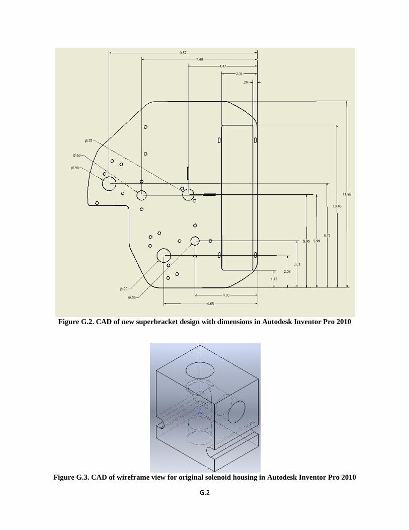
G.2
Figure G.2. CAD of new superbracket design with dimensions in Autodesk Inventor Pro 2010
Figure G.3. CAD of wireframe view for original solenoid housing in Autodesk Inventor Pro 2010

G.3
Figure G.4. CAD of wireframe view for old prototype’s solenoid housing in Autodesk Inventor Pro
2010
Figure G.5. Dimensional drawing for new solenoid housing in Autodesk Inventor Pro 2010
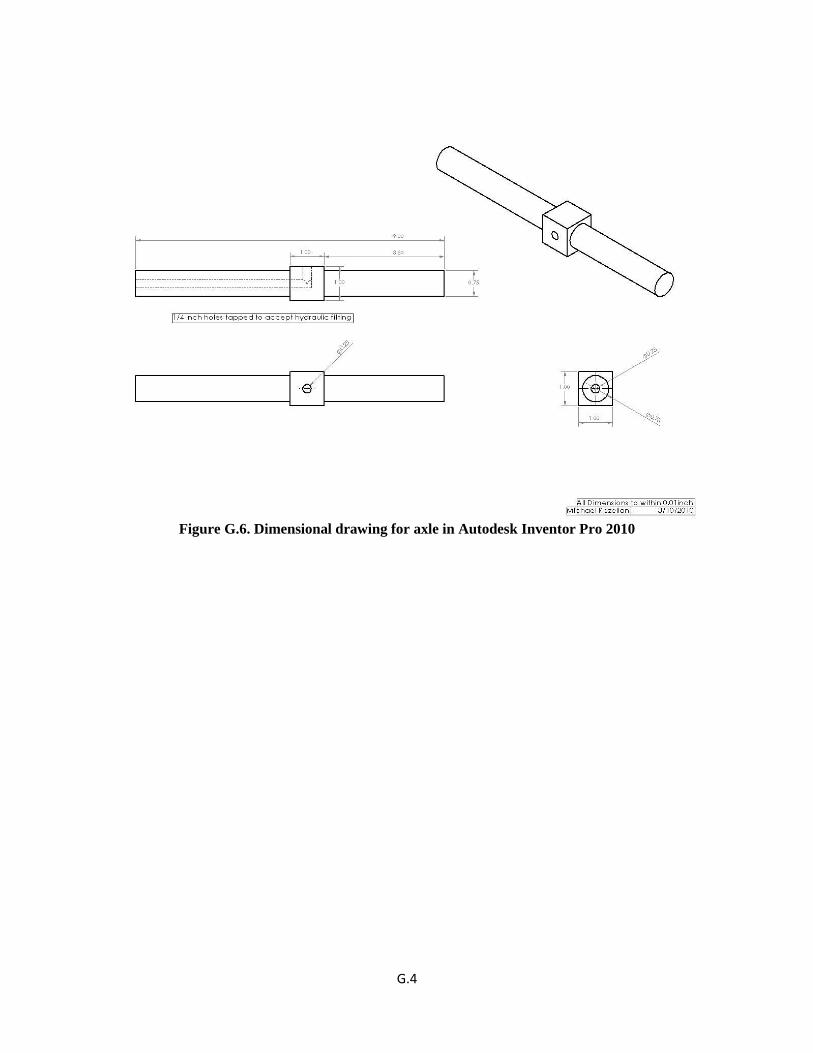
G.4
Figure G.6. Dimensional drawing for axle in Autodesk Inventor Pro 2010

G.5
Figure G.7. Dimensional drawing for modified 5” gear in Autodesk Inventor Pro 2010 [10]

G.6
Figure G.8. Dimensional drawing for modified 3.5” gear in Autodesk Inventor Pro 2010 [10]

Figure G.9. Dimensional drawing for new superbracket (hole features)

Figure G.10. Dimensional drawing for new superbracket (major features)

Figure G.11. Dimensional drawing for Hub Carriers

Figure G.12. Dimensional drawing for pushbutton adapters

Figure G.13. Dimensional drawing for pump 3.5” gear
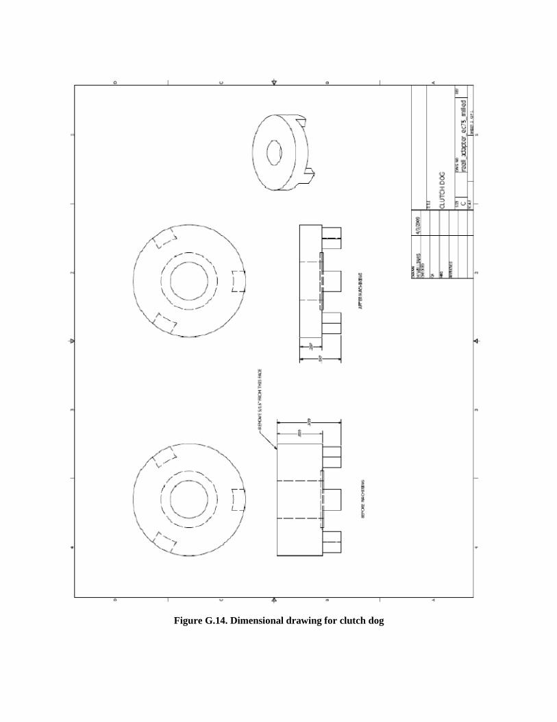
Figure G.14. Dimensional drawing for clutch dog

Figure G.15. Dimensional drawing for clutch stabilizer
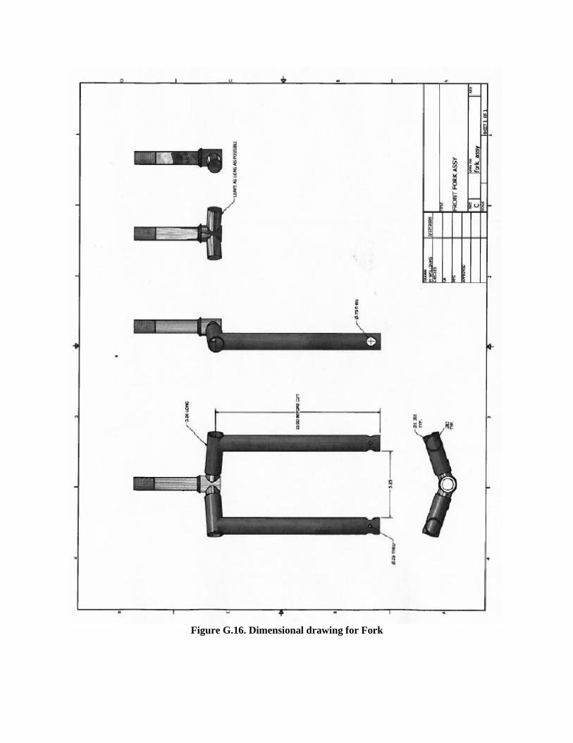
Figure G.16. Dimensional drawing for Fork

Figure G.17. Dimensional drawing for the Rim

Figure G.18. Dimensional drawing of the shaft for the 3.5 gear on the motor side

Figure G.19. Dimensional drawing of the shaft for the clutch

Appendix H – CAD of assembly
Figure H.1. Hub Assembly explosion

Figure H.2. Hydraulic Assembly explosion
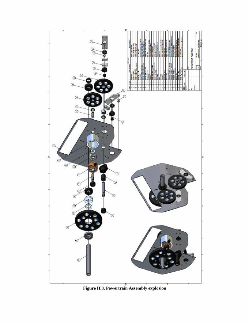
Figure H.3. Powertrain Assembly explosion

Appendix J – Winter ’09 Team 24’s Simulink Models
Figure J1. Motor and pump Simulink transmission model
Figure J2. Bike system Simulink model

Appendix K – Calculations for requirements of the HRBS in a wheelchair
Elevation Specs:
[1] Bonisteel to Duffield – small hill
Rise: 35 feet = 10.668 m
Run: 871.86 feet
Slope: 2.30 degrees
[2] Bonisteel to Hayward - big hill
Rise: 65 feet = 19.812 m
Run: 1281.22 feet
Slope: 2.90 degrees
[3] Fuller to Bonisteel - other hill
Rise: 35 feet = 10.668 m
Run: 1034.36 feet
Slope: 1.94 degrees
Other Specs:
User: 200 lbs = 90.72 kg
Wheelchair: 35 lbs = 15.88 kg
Wheelchair + kid: 106.6 kg
Average accumulator pressure: 3200 Psi = 22063.22 kPa
The maximum speed of electric powerchairs is 12 m/s. Therefore calculations based on 12 m/s are to be
used when determining flow rate.
Decelerating: 4.5 mph = 2 m/s
Accelerating: 7.82927702 mph = 3.5 m/s
Max speed: 12 mph = 5.36448 m/s
Calculations:
Slopes-
𝑇𝑎𝑛 = 𝑂𝑝𝑝𝑜𝑠𝑖𝑡𝑒
𝐴𝑑𝑗𝑎𝑐𝑒𝑛𝑡=
𝑅𝑖𝑠𝑒
𝑅𝑢𝑛
𝑇𝑎𝑛−1( 𝑅𝑖𝑠𝑒
𝑅𝑢𝑛) = 𝑆𝑙𝑜𝑝𝑒 𝑖𝑛 𝐷𝑒𝑔𝑟𝑒𝑒𝑠
Energy
[1] and [3] – (hills have same height)
𝐸𝑛𝑒𝑟𝑔𝑦 𝐽𝑜𝑢𝑙𝑒𝑠 = 𝑀𝑎𝑠𝑠 𝑘𝑔 ∗ 𝐺𝑟𝑎𝑣𝑖𝑡𝑦 𝑚
𝑠2 ∗ 𝐻𝑒𝑖𝑔𝑡 [𝑚] (Eq. X)
𝐸 = 𝑚 ∗ 𝑔 ∗ (Eq. X)
𝐸𝑛𝑒𝑟𝑔𝑦 = 106.6[𝑘𝑔] ∗ 9.81 𝑚
𝑠2 ∗ 10.67[𝑚] = 11158.11 𝐽𝑜𝑢𝑙𝑒𝑠 (Eq. X)
𝐸 = 𝑃𝑟𝑒𝑠𝑠𝑢𝑟𝑒 𝑘𝑃𝑎 ∗ 𝑉𝑜𝑙𝑢𝑚𝑒 [𝐿] (Eq. X)
𝐸 = 𝑃 ∗ 𝑉 (Eq. X)

𝑉 = 𝐸[𝐽 ]
𝑃 [𝑘𝑃𝑎 ]=
11158 .11 𝐽
22063 .22 𝑘𝑃𝑎= 0.51 𝐿𝑖𝑡𝑒𝑟𝑠 (Eq. X)
[2] big hill
𝐸 = 106.6[𝑘𝑔] ∗ 9.81 𝑚
𝑠2 ∗ 19.81[𝑚] = 20716.23 𝐽 (Eq. X)
𝑽 𝑳 = 𝑬 𝑱𝒐𝒖𝒍𝒆𝒔
𝑷 𝒌𝑷𝒂 =
𝟐𝟎𝟕𝟏𝟔.𝟐𝟑 𝑱
𝟐𝟐𝟎𝟔𝟑.𝟐𝟐 𝒌𝑷𝒂= 𝟎. 𝟗𝟒 𝑳𝒊𝒕𝒆𝒓𝒔 (Eq. X)
Power
v values are velocity in the horizontal direction of the incline
For slowing down:
[1] small hill
𝑃𝑜𝑤𝑒𝑟 𝑊𝑎𝑡𝑡𝑠 = 𝑀𝑎𝑠𝑠 𝐾𝑔 ∗ 𝐺𝑟𝑎𝑣𝑖𝑡𝑦 𝑚
𝑠2 ∗ 𝑉𝑒𝑙𝑜𝑐𝑖𝑡𝑦 [𝑚
𝑠] (Eq. X)
𝑊 𝑊𝑎𝑡𝑡𝑠 = 𝑚 𝐾𝑔 ∗ 𝑔 𝑚
𝑠2 ∗ 𝑣 [𝑚
𝑠] (Eq. X)
2 sin(2.30) = 0.08 (Eq. X)
𝑊 𝑊𝑎𝑡𝑡𝑠 = 106.6[𝑘𝑔] ∗ 9.81 𝑚
𝑠2 ∗ 0.08[𝑚
𝑠] = 83.66 𝑊𝑎𝑡𝑡𝑠 (Eq. X)
𝑉 [𝐿
𝑠] =
𝑃𝑜𝑤𝑒𝑟 𝑊𝑎𝑡𝑡𝑠
𝑃𝑟𝑒𝑠𝑠𝑢𝑟𝑒 𝑘𝑃𝑎 =
83.66𝑊
22063 .22 𝑘𝑃𝑎= 0.004 𝐿/𝑠 (Eq. X)
[2] big hill
2 sin 2.90 = 0.10 (Eq. X)
𝑃𝑜𝑤𝑒𝑟 𝑊𝑎𝑡𝑡𝑠 = 106.6 𝐾𝑔 ∗ 9.81 𝑚
𝑠2 ∗ 0.101[𝑚
𝑠] = 105.62 𝑊𝑎𝑡𝑡𝑠 (Eq. X)
𝑃𝑜𝑤𝑒𝑟 [𝑊𝑎𝑡𝑡𝑠] = 𝑉 [𝐿
𝑠] ∗ 𝑃𝑟𝑒𝑠𝑠𝑢𝑟𝑒 [𝑘𝑃𝑎] (Eq. X)
𝑉 𝐿
𝑠 =
𝑃𝑜𝑤𝑒𝑟 [𝑊𝑎𝑡𝑡𝑠 ]
𝑃𝑟𝑒𝑠𝑠𝑢𝑟𝑒 [𝑘𝑃𝑎 ]=
105.62 𝑊𝑎𝑡𝑡𝑠
22063 .22 𝑘𝑃𝑎= 0.005 𝐿/𝑠 (Eq. X)
[3] Other small hill
2 sin 1.94 = 0.07 (Eq. X)
𝑃𝑜𝑤𝑒𝑟 [𝑊𝑎𝑡𝑡𝑠] = 106.6 [𝑘𝑔] ∗ 9.81 𝑚
𝑠2 ∗ 0.07 𝑚/𝑠 = 73.20 𝑊𝑎𝑡𝑡𝑠 (Eq. X)
𝑉 [𝐿
𝑠] =
𝑃𝑜𝑤𝑒𝑟 𝑊𝑎𝑡𝑡𝑠
𝑃𝑟𝑒𝑠𝑠𝑢𝑟𝑒 𝐾𝑃𝑎 =
73.20 𝑊𝑎𝑡𝑡𝑠
22063 .22 𝐾𝑃𝑎= 0.003 𝐿/𝑠 (Eq. X)
For speeding up:
θ g
θ
x
x = 2 m/s for slowing down
x = 3.5 m/s for speeding up
x = 5.4 m/s for maximum speed

[1] small hill
3.5 sin(2.30) = 0.14 (Eq. X)
𝑊 𝑊𝑎𝑡𝑡𝑠 = 106.6[𝑘𝑔] ∗ 9.81 𝑚
𝑠2 ∗ 0.14[𝑚
𝑠] = 146.40 𝑊𝑎𝑡𝑡𝑠 (Eq. X)
𝑉 [𝐿
𝑠] =
𝑃𝑜𝑤𝑒𝑟 𝑊𝑎𝑡𝑡𝑠
𝑃𝑟𝑒𝑠𝑠𝑢𝑟𝑒 𝑘𝑃𝑎 =
146.40 𝑊
22063 .22 𝑘𝑃𝑎= 0.007 𝐿/𝑠 (Eq. X)
[2] big hill
3.5 sin 2.90 = 0.18 (Eq. X)
𝑃𝑜𝑤𝑒𝑟 𝑊𝑎𝑡𝑡𝑠 = 106.6 𝐾𝑔 ∗ 9.81 𝑚
𝑠2 ∗ 0.18[𝑚
𝑠] = 188.23 𝑊𝑎𝑡𝑡𝑠 (Eq. X)
𝑃𝑜𝑤𝑒𝑟 [𝑊𝑎𝑡𝑡𝑠] = 𝑉 [𝐿
𝑠] ∗ 𝑃𝑟𝑒𝑠𝑠𝑢𝑟𝑒 [𝑘𝑃𝑎] (Eq. X)
𝑉 𝐿
𝑠 =
𝑃𝑜𝑤𝑒𝑟 [𝑊𝑎𝑡𝑡𝑠 ]
𝑃𝑟𝑒𝑠𝑠𝑢𝑟𝑒 [𝑘𝑃𝑎 ]=
188.23 𝑊𝑎𝑡𝑡𝑠
22063 .22 𝑘𝑃𝑎= 0.009 𝐿/𝑠 (Eq. X)
[3] Other small hill
3.5 sin 1.94 = 0.12 (Eq. X)
𝑃𝑜𝑤𝑒𝑟 [𝑊𝑎𝑡𝑡𝑠] = 106.6 [𝑘𝑔] ∗ 9.81 𝑚
𝑠2 ∗ 0.12 𝑚/𝑠 = 125.49 𝑊𝑎𝑡𝑡𝑠 (Eq. X)
𝑉 [𝐿
𝑠] =
𝑃𝑜𝑤𝑒𝑟 𝑊𝑎𝑡𝑡𝑠
𝑃𝑟𝑒𝑠𝑠𝑢𝑟𝑒 𝐾𝑃𝑎 =
125.49 𝑊𝑎𝑡𝑡𝑠
22063 .22 𝐾𝑃𝑎= 0.006 𝐿/𝑠 (Eq. X)
For maximum speed:
[1] small hill
5.4 sin(2.30) = 0.22 (Eq. X)
𝑊 𝑊𝑎𝑡𝑡𝑠 = 106.6[𝑘𝑔] ∗ 9.81 𝑚
𝑠2 ∗ 0.22[𝑚
𝑠] = 230.06 𝑊𝑎𝑡𝑡𝑠 (Eq. X)
𝑉 [𝐿
𝑠] =
𝑃𝑜𝑤𝑒𝑟 𝑊𝑎𝑡𝑡𝑠
𝑃𝑟𝑒𝑠𝑠𝑢𝑟𝑒 𝑘𝑃𝑎 =
230.06 𝑊
22063 .22 𝑘𝑃𝑎= 0.010 𝐿/𝑠 (Eq. X)
[2] big hill
5.4 sin 2.90 = 0.27 (Eq. X)
𝑃𝑜𝑤𝑒𝑟 𝑊𝑎𝑡𝑡𝑠 = 106.6 𝐾𝑔 ∗ 9.81 𝑚
𝑠2 ∗ 0.27[𝑚
𝑠] = 282.35 𝑊𝑎𝑡𝑡𝑠 (Eq. X)
𝑃𝑜𝑤𝑒𝑟 [𝑊𝑎𝑡𝑡𝑠] = 𝑉 [𝐿
𝑠] ∗ 𝑃𝑟𝑒𝑠𝑠𝑢𝑟𝑒 [𝑘𝑃𝑎] (Eq. X)
𝑽 𝑳
𝒔 =
𝑷𝒐𝒘𝒆𝒓 [𝑾𝒂𝒕𝒕𝒔]
𝑷𝒓𝒆𝒔𝒔𝒖𝒓𝒆 [𝒌𝑷𝒂]=
𝟐𝟖𝟐.𝟑𝟓 𝑾𝒂𝒕𝒕𝒔
𝟐𝟐𝟎𝟔𝟑.𝟐𝟐 𝒌𝑷𝒂= 𝟎. 𝟎𝟏𝟑 𝑳/𝒔 (Eq. X)
[3] Other small hill
5.4 sin 1.94 = 0.18 (Eq. X)
𝑃𝑜𝑤𝑒𝑟 [𝑊𝑎𝑡𝑡𝑠] = 106.6 [𝑘𝑔] ∗ 9.81 𝑚
𝑠2 ∗ 0.18 𝑚/𝑠 = 188.23 𝑊𝑎𝑡𝑡𝑠 (Eq. X)
𝑉 [𝐿
𝑠] =
𝑃𝑜𝑤𝑒𝑟 𝑊𝑎𝑡𝑡𝑠
𝑃𝑟𝑒𝑠𝑠𝑢𝑟𝑒 𝐾𝑃𝑎 =
188.23𝑊𝑎𝑡𝑡𝑠
22063 .22 𝐾𝑃𝑎= 0.009 𝐿/𝑠 (Eq. X)
Assume 18:1 Gear Ratio
For [2]
𝑃𝑜𝑤𝑒𝑟 [𝑊𝑎𝑡𝑡𝑠] = 𝐷𝑖𝑠𝑝𝑙𝑎𝑐𝑒𝑚𝑒𝑛𝑡 𝐿
𝑟𝑒𝑣 ∗ 𝜔
𝑅𝑒𝑣
𝑠 ∗ 𝑃𝑟𝑒𝑠𝑠𝑢𝑟𝑒 [𝐾𝑃𝑎] (Eq. X)
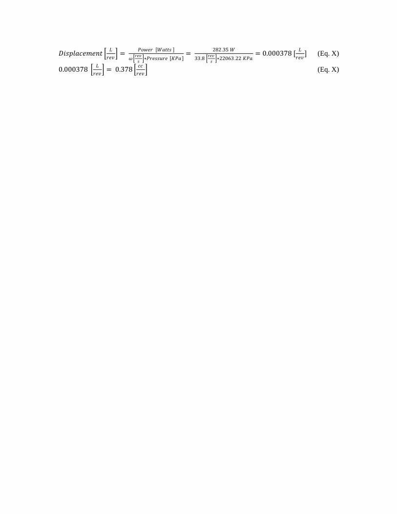
𝐷𝑖𝑠𝑝𝑙𝑎𝑐𝑒𝑚𝑒𝑛𝑡 𝐿
𝑟𝑒𝑣 =
𝑃𝑜𝑤𝑒𝑟 𝑊𝑎𝑡𝑡𝑠
𝜔 𝑟𝑒𝑣
𝑠 ∗𝑃𝑟𝑒𝑠𝑠𝑢𝑟𝑒 𝐾𝑃𝑎
= 282.35 𝑊
33.8 𝑟𝑒𝑣
𝑠 ∗22063 .22 𝐾𝑃𝑎
= 0.000378 [𝐿
𝑟𝑒𝑣] (Eq. X)
0.000378 𝐿
𝑟𝑒𝑣 = 0.378
𝑐𝑐
𝑟𝑒𝑣 (Eq. X)

Appendix L – Team Biography’s
Name: Michael Kezelian
Contact #: 248-229-1518
Mike grew up in Beverly Hills Michigan. He is a 5th year ME student and
has lived in a house across the street from the IM building for the last four
years. He is a 5th year because he spent 2 years as an active member of
the Solar Car Team. He was part of the Continuum project and was
selected to be on the race crew for the 2007 World Solar Challenge in
Australia (he spent about 3 months down under and placed 7th) and the
2008 North American Solar Challenge (they won!). During his time with
the team he gained skill with certain CAD programs (mostly SolidWorks)
and machining (mostly manual mill work). Over the past summer, he had
an internship at Novellus Engineering, a company that contracts for Ford.
He learned quite a bit about visual basic programming while with them. He played hockey for 10 years
but unfortunately stopped when he came to college. He is currently the sports chair for the UofM
Armenian Club and organizes and participates in a number of IM sports throughout the year. He is
currently playing Basketball and Dodgeball. He is thoroughly obsessed with cars. Summer 2010 he will
be participating in the Skip Barber High Performance Driving School at Mazda Raceway Leguna Seca.
He hopes to one day have some real impact on something that people drive.
Name: Heather Li
Contact #: 616.298.1093
Background: Heather was born in Wisconsin but lived in Taiwan for 6 years
before starting elementary school in Michigan. Her hometown is Grand
Haven, MI. She is a senior at UofM and will be graduating May 2010. She is
a very curious person by nature and is constantly asking questions to better
understand/learn how something works. She currently works at the machine
shop in GGBrown and loves her job because tools and machines fascinate her.
She is definitely a hands-on/visual learner and enjoys taking things apart and
constructing them back together.
Strengths: Heather is very proficient in writing, sufficient in CAD and only
familiar with computer programming. She enjoys math and therefore enjoys
doing anything with analytical problem solving and straightforward
calculations (rather than theoretical problems). She tends to get nervous when
speaking in front of a large crowd for presentations. However, she has been in
the restaurant business for 6 years so she has good people skills when it comes
to speaking with anybody personally. Another forte of hers is music (she plays
4 instruments) and the arts (drawing and painting) so she enjoys combining
creativity and thinking outside of the box. She is also very organized and detailed with everything she
does/learns.
Interests: Heather is highly interested in energy efficiency, environmentally friendly products, recycling,
and anything else that can improve the environment. She also loves cars and is an avid supporter for
hybrid/electric vehicles. Her dream job would be working for a car company that designs and produces
EV's.

L.2
Name: Alekhya Ratnala
Contact #: (248)-719-2597
Background: Alekhya was born and raised in South India and moved to the
United States with her family when she was 11 years old. Since then she
lived in Novi, Michigan. She is currently a 5th year Mechanical engineering
Student at University of Michigan and will be graduating this coming May.
She is currently in the process of applying for jobs, as she wants to get a feel
for the field and find something she is passionate about, and then pursue
graduate school depending on what she finds interesting. She has spent her
freshman year in a research position at the department of Ecology and Evolutionary Biology studying
fruit flies due to her interest in genetics. Some of her strengths include CAD modeling, Analytical
calculations and technical writing. She is not a strong public speaker and very much an introvert. She is
currently spending her spare time getting proficient at MATLAB/Simulink as she finds it a very
interesting and powerful software. Her favorite engineering classes are heat transfer, fluid mechanics,
material sciences and manufacturing. Alekhya would like to find a job in the green engineering field and
contribute to the protection of the environment.
Interests/hobbies: Alekhya had an interest of the arts since an early age; she spends her spare time
sketching, painting, Clay modeling, or with photography. She likes to spend a lot of time on Wikipedia
learning about a lot of random things. She also enjoys gardening very much and spends much of winter
contemplating and being excited about what plants to grow in spring. She is currently learning piano at
the U of M School of Music as she has always wanted to learn a music instrument. She is a fan of the
Detroit Pistons and the Indian Cricket Team.
Name: Hai Wang
Contact #: (626)241-8997
Hai was born and raised in China. He transferred from Shanghai
Jiaotong University to UofM 2 years ago. He is good at Finite
element analysis, mechanical behavior of materials, solid
mechanics and minimally proficient at CAD. He is working in a
Bio-lab to study the cracks on PDMS (a kind of polymer) micor-
spheres now. He has applied for graduate school. He likes to play
basketball on the weekend for fun. He also like to know how
thing works and is interested in materials and their behaviors. He
doesn’t have a lot of experience with manufacturing, but he hopes
we can apply some creative ideas in this project and make a
breakthrough.