rddm rotary direct drive motors - endolineer.com advantages of rotary direct drives increases...
TRANSCRIPT
RDDM
Rotary Direct Drive Motors
2
INA - Drives & Mechatronics GmbH & Co.
oHG, a company of the Schaeffler Group,
specializes in linear and rotary direct
drives. These products are supplemented
by directly driven positioning systems
and related controllers and mechatronics
assemblies.
In addition to standard products, IDAM
also develops and produces customized
drive solutions.
Due to the increasing demands in terms
of dynamic performance, precision and
cost reduction, direct drives are be com -
ing increasingly more popular in modern
machinery and equipment.
IDAM has developed a standard series of highly efficient rotary motors that are
shown in this catalog. With this standard motor series as a starting point,
customer specific, customized motors can be developed and produced in low or
high volume.
The Perfect Drive for Every Application
The direct connection between motor
and accelerated mass increases dyna -
mic and static rigidity, reduces elasticity
and therefore enables an extremely
high level of positioning performance.
Direct drives are non-wearing, as a
result of which maintenance and
operat ing costs can be reduced whilst
simultaneously increasing availability.
In the industries of machine tools and
production machinery, automation,
productronics/semicon, measuring
technology and medical technology,
teams at IDAM have been developing
direct drives and complex drive systems
since 1990.
The development of the direct drives
and the positioning systems is effi -
ciently supported by the integration
of models and simulations.
IDAM employs a state-of-the-art quality
management system. At IDAM, quality
management is a dynamic process
which is examined on a daily basis and
is thus continuously improved. IDAM is
certified according to standard DIN EN
ISO 9001:2008.
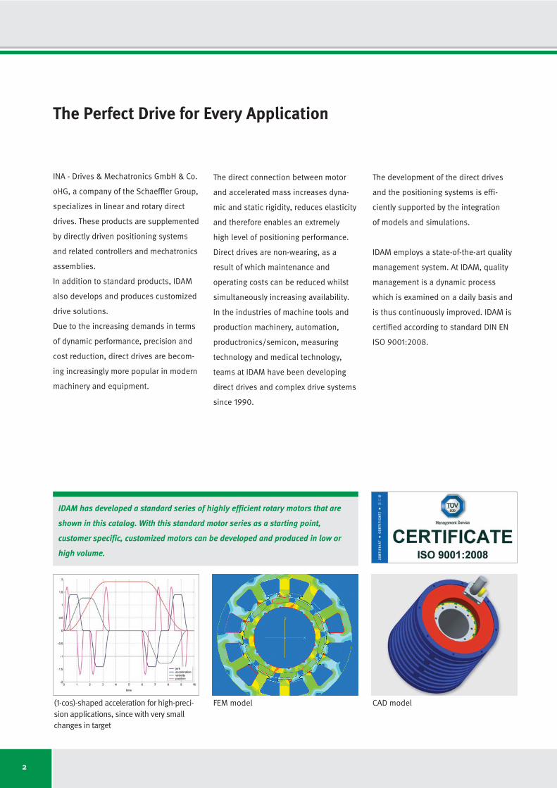
CAD model(1-cos)-shaped acceleration for high-preci-sion applications, since with very smallchanges in target
FEM model
3
Table of Contents
Technical Principles
Advantages of Rotary Direct Drives . . . . . . . . . . . . . . . . . . . . . . . . . . . . . . . . . . . . . . . . . . . . . . . . . . . . . . . . . . . . . . . . . . . . . . . . . . . . . . .4
Characteristics of Frameless Motors . . . . . . . . . . . . . . . . . . . . . . . . . . . . . . . . . . . . . . . . . . . . . . . . . . . . . . . . . . . . . . . . . . . . . . . . . . . . . .5
General Motor Characteristics – Efficiency . . . . . . . . . . . . . . . . . . . . . . . . . . . . . . . . . . . . . . . . . . . . . . . . . . . . . . . . . . . . . . . . . . . . . . . . .6
Winding Options . . . . . . . . . . . . . . . . . . . . . . . . . . . . . . . . . . . . . . . . . . . . . . . . . . . . . . . . . . . . . . . . . . . . . . . . . . . . . . . . . . . . . . . . . . . . . .7
Torque-Rotary Speed Characteristic . . . . . . . . . . . . . . . . . . . . . . . . . . . . . . . . . . . . . . . . . . . . . . . . . . . . . . . . . . . . . . . . . . . . . . . . . . . . . .8
Torque-Current Characteristic . . . . . . . . . . . . . . . . . . . . . . . . . . . . . . . . . . . . . . . . . . . . . . . . . . . . . . . . . . . . . . . . . . . . . . . . . . . . . . . . . . .9
Thermal Motor Protection Cutout . . . . . . . . . . . . . . . . . . . . . . . . . . . . . . . . . . . . . . . . . . . . . . . . . . . . . . . . . . . . . . . . . . . . . . . . . . . . . . . .10
Electrical Connections . . . . . . . . . . . . . . . . . . . . . . . . . . . . . . . . . . . . . . . . . . . . . . . . . . . . . . . . . . . . . . . . . . . . . . . . . . . . . . . . . . . . . . . .12
Commutation . . . . . . . . . . . . . . . . . . . . . . . . . . . . . . . . . . . . . . . . . . . . . . . . . . . . . . . . . . . . . . . . . . . . . . . . . . . . . . . . . . . . . . . . . . . . . . . .13
Insulation Strength . . . . . . . . . . . . . . . . . . . . . . . . . . . . . . . . . . . . . . . . . . . . . . . . . . . . . . . . . . . . . . . . . . . . . . . . . . . . . . . . . . . . . . . . . . .13
Cooling and Cooling Circuits . . . . . . . . . . . . . . . . . . . . . . . . . . . . . . . . . . . . . . . . . . . . . . . . . . . . . . . . . . . . . . . . . . . . . . . . . . . . . . . . . . .14
Dependency of the Rating Data on the Supply Temperature . . . . . . . . . . . . . . . . . . . . . . . . . . . . . . . . . . . . . . . . . . . . . . . . . . . . . . . . . .15
Selection of Direct Drives for Rotary Applications . . . . . . . . . . . . . . . . . . . . . . . . . . . . . . . . . . . . . . . . . . . . . . . . . . . . . . . . . . . . . . . . . .16
Product Range
Availability/Selection of Sizes: Series RI . . . . . . . . . . . . . . . . . . . . . . . . . . . . . . . . . . . . . . . . . . . . . . . . . . . . . . . . . . . . . . . . . . . . . . . . .20
Designation: Series RI . . . . . . . . . . . . . . . . . . . . . . . . . . . . . . . . . . . . . . . . . . . . . . . . . . . . . . . . . . . . . . . . . . . . . . . . . . . . . . . . . . . . . . . . .21
Motor Specifications: Series RI . . . . . . . . . . . . . . . . . . . . . . . . . . . . . . . . . . . . . . . . . . . . . . . . . . . . . . . . . . . . . . . . . . . . . . . . . . . . . . . . .22
Availability/Selection of Sizes: Series RE . . . . . . . . . . . . . . . . . . . . . . . . . . . . . . . . . . . . . . . . . . . . . . . . . . . . . . . . . . . . . . . . . . . . . . . . .54
Designation: Series RE . . . . . . . . . . . . . . . . . . . . . . . . . . . . . . . . . . . . . . . . . . . . . . . . . . . . . . . . . . . . . . . . . . . . . . . . . . . . . . . . . . . . . . . .55
Motor Specifications: Series RE . . . . . . . . . . . . . . . . . . . . . . . . . . . . . . . . . . . . . . . . . . . . . . . . . . . . . . . . . . . . . . . . . . . . . . . . . . . . . . . . .56
Availability/Selection of Sizes: Type RMK • RMF . . . . . . . . . . . . . . . . . . . . . . . . . . . . . . . . . . . . . . . . . . . . . . . . . . . . . . . . . . . . . . . . . . .84
Designation: Type RMK • RMF . . . . . . . . . . . . . . . . . . . . . . . . . . . . . . . . . . . . . . . . . . . . . . . . . . . . . . . . . . . . . . . . . . . . . . . . . . . . . . . . . .85
Availability/Selection of Sizes: Type HSR • HSRV . . . . . . . . . . . . . . . . . . . . . . . . . . . . . . . . . . . . . . . . . . . . . . . . . . . . . . . . . . . . . . . . . .86
Designation: Type HSR • HSRV . . . . . . . . . . . . . . . . . . . . . . . . . . . . . . . . . . . . . . . . . . . . . . . . . . . . . . . . . . . . . . . . . . . . . . . . . . . . . . . . .87
Segment Motors . . . . . . . . . . . . . . . . . . . . . . . . . . . . . . . . . . . . . . . . . . . . . . . . . . . . . . . . . . . . . . . . . . . . . . . . . . . . . . . . . . . . . . . . . . . . .88
Motors in Special Structural Shapes . . . . . . . . . . . . . . . . . . . . . . . . . . . . . . . . . . . . . . . . . . . . . . . . . . . . . . . . . . . . . . . . . . . . . . . . . . . . .89
General Information
Check List for Your Enquiry . . . . . . . . . . . . . . . . . . . . . . . . . . . . . . . . . . . . . . . . . . . . . . . . . . . . . . . . . . . . . . . . . . . . . . . . . . . . . . . . . . . .90
Technical Information and Consulting Services . . . . . . . . . . . . . . . . . . . . . . . . . . . . . . . . . . . . . . . . . . . . . . . . . . . . . . . . . . . . . . . . . . . .92
IDAM Worldwide . . . . . . . . . . . . . . . . . . . . . . . . . . . . . . . . . . . . . . . . . . . . . . . . . . . . . . . . . . . . . . . . . . . . . . . . . . . . . . . . . . . . . . . . . . . . .93
Glossary . . . . . . . . . . . . . . . . . . . . . . . . . . . . . . . . . . . . . . . . . . . . . . . . . . . . . . . . . . . . . . . . . . . . . . . . . . . . . . . . . . . . . . . . . . . . . . . . . . .94
At a Glance: IDAM Brochures . . . . . . . . . . . . . . . . . . . . . . . . . . . . . . . . . . . . . . . . . . . . . . . . . . . . . . . . . . . . . . . . . . . . . . . . . . . . . . . . . . .99
At a Glance: Torque Ranges of the RI/RE Motors . . . . . . . . . . . . . . . . . . . . . . . . . . . . . . . . . . . . . . . . . . . . . . . . . . . . . . . . . . . . . . . . . .100
4
Advantages of Rotary Direct Drives
Increases dynamic capacity
1. No conversion of motion form
• With a direct drive motor system,
there is no need for mechanical
linkage (gearbox, belt, etc.) bet-
ween the payload and the motor.
Thus there are no backlash, clea-
rance, friction, or elasticity prob-
lems. This makes for a much
stiffer and more easily controlled
system.
2. Multi-pole motor
• With a multi-pole design, IDAM
motors are capable of producing
very high torque. In addition, this
high torque can also be sustained
over a much greater speed range.
3. Thin, ring-shaped rotor
• Thanks to the thin, ring-shaped
design with a large, open inner
diameter, the motor is able to
produce high torque with a very
low rotor inertia. This allows for
very high motor acceleration
capabilities.
4. External rotor design option
• With an external rotor, the motor
can produce higher torque in a
smaller package than to an inter-
nal rotor motor.
5. Direct position measurement
• Thanks to the direct position mea-
surement of the feedback system
combined with a rigid mechanical
structure, highly accurate and
dynamic positioning is possible.
Reduces operating costs
1. Fewer components
• With a direct drive system, fewer
components are required. This al-
lows for easier assembly and align-
ment along with a substantial
reduction in maintenance. The
reduced number of components
enables a much more streamlined
supply chain. Also,with fewer com-
ponents, the modes of failure are
greatly reduced and thus greatly
increases the MTBF*.
2. No wear in the drive train
• Because motor power is transmit-
ted through an air gap and not
through mechanical components,
a direct drive motor system has an
extremely long life even with very
demanding duty cycles.
• This substantially reduces machine
down-time.
3. Reduces machine down-time
• In addition to the increased life and
reduced wear, the robustness of a
torque motor substantially reduces
machine down-time.
• With direct drive torque motors,
mechanical overload does not
damage the drive train as is the
case with geared motors.
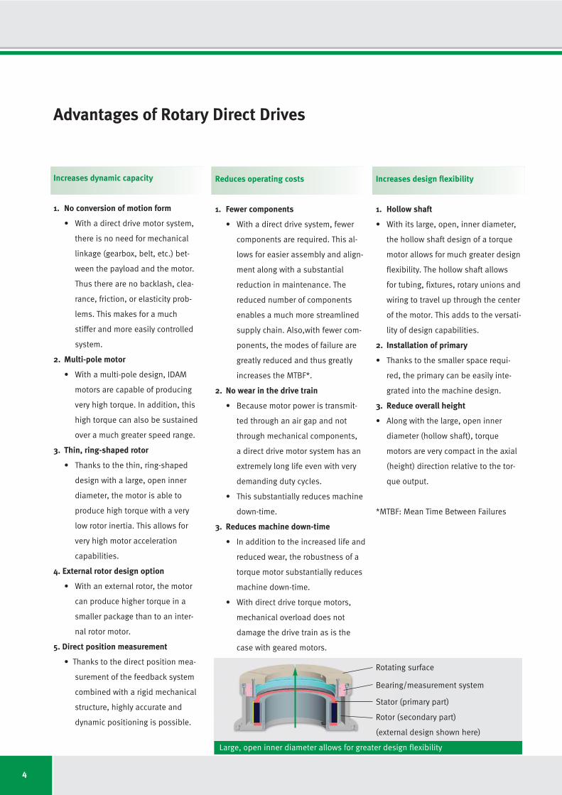
Increases design flexibility
1. Hollow shaft
• With its large, open, inner diameter,
the hollow shaft design of a torque
motor allows for much greater design
flexibility. The hollow shaft allows
for tubing, fixtures, rotary unions and
wiring to travel up through the center
of the motor. This adds to the versati-
lity of design capabilities.
2. Installation of primary
• Thanks to the smaller space requi-
red, the primary can be easily inte-
grated into the machine design.
3. Reduce overall height
• Along with the large, open inner
diameter (hollow shaft), torque
motors are very compact in the axial
(height) direction relative to the tor-
que output.
*MTBF: Mean Time Between Failures
Rotating surface
Bearing/measurement system
Rotor (secondary part)
(external design shown here)
Stator (primary part)
Large, open inner diameter allows for greater design flexibility
5
Rotary frameless motors consist of a pri-
mary winding and a secondary winding.
The primary contains an active coil system
and the secondary has a permanent
magnet system.
The rotor can be either internal or exter-
nal (RI series and RE series) relative to
the primary (stator).
When current is supplied to the primary
(coil system), electromagnetic force pro-
duces torque in the secondary.
A guidance system (rolling element or air
bearing) is required to maintain a con-
sistent air gap between the primary and
the secondary. A measuring system is
also needed for determining rotor posi-
tion for motor commutation purposes.
The proper selection of these and other
essential motor system components is
based on many years of IDAM applica -
tion experience.
IDAM offers different motor designs for
different customer application require-
ments. Rotary, frameless motors mainly
differ in design by whether the motor is
slotted, slotless or ironless. These mo -
tors produce a high, consistent torque
across a wide range of speeds. The torque
output is determined by the active air
gap surface area between the primary
(stator) and the secondary (rotor).
The proper motor selection depends on
the required performance.
Unlike conventional motors, frameless
motors are classified according to the
required torque, not to the electrical
rating.
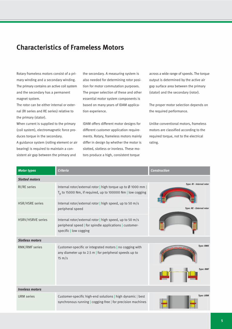
Characteristics of Frameless Motors
Construction
Type: RMF
Type: RE - External rotor
Slotted motorsType: RI - Internal rotor
Slotless motors
Ironless motors
Type: RMK
Motor types
RI/RE series
HSR/HSRE series
HSRV/HSRVE series
RMK/RMF series
URM series
Criteria
Internal rotor/external rotor | high torque up to Ø 1000 mm |
Tp to 15000 Nm, if required, up to 100000 Nm | low cogging
Internal rotor/external rotor | high speed, up to 50 m/s
peripheral speed
Internal rotor/external rotor | high speed, up to 50 m/s
peripheral speed | for spindle applications | customer-
specific | low cogging
Customer-specific or integrated motors | no cogging with
any diameter up to 2.5 m | for peripheral speeds up to
15 m/s
Customer-specific high-end solutions | high dynamic | best
synchronous running | cogging-free | for precision machines
Type: URM
6
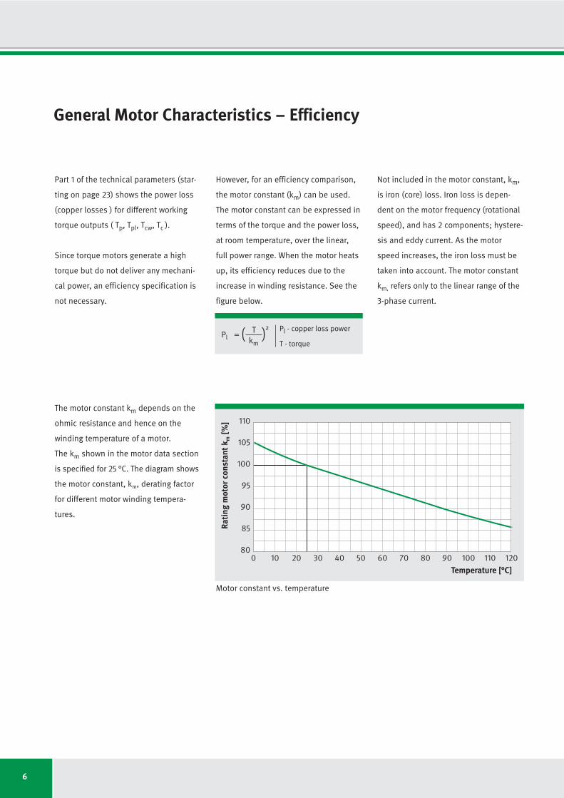
General Motor Characteristics – Efficiency
The motor constant km depends on the
ohmic resistance and hence on the
wind ing temperature of a motor.
The km shown in the motor data section
is specified for 25 °C. The diagram shows
the motor constant, km, derating factor
for different motor winding tempera -
tures.
Part 1 of the technical parameters (star-
ting on page 23) shows the power loss
(copper losses ) for different working
torque outputs ( Tp, Tpl, Tcw, Tc ).
Since torque motors generate a high
torque but do not deliver any mechani-
cal power, an efficiency specification is
not necessary.
0 10 20 30 40 50 60 70 80 90 100 110 120
80
85
90
95
100
105
110
Rati
ng m
otor
con
stan
t km
[%]
Temperature [°C]
However, for an efficiency comparison,
the motor constant (km) can be used.
The motor constant can be expressed in
terms of the torque and the power loss,
at room temperature, over the linear,
full power range. When the motor heats
up, its efficiency reduces due to the
increase in winding resistance. See the
figure below.
Not included in the motor constant, km,
is iron (core) loss. Iron loss is depen-
dent on the motor frequency (rotational
speed), and has 2 components; hystere-
sis and eddy current. As the motor
speed increases, the iron loss must be
taken into account. The motor constant
km, refers only to the linear range of the
3-phase current.
PlT=
km( )
2 Pl - copper loss power
T - torque
Motor constant vs. temperature
7
Winding Options
The maximum rotational speed of a torque
motor depends mainly on the winding
configuration and the operating voltage
(UDCL).
As rotational speed increases, the Back
EMF voltage also increases, which count -
ers the input voltage. At the rotational
speed limits (nd, nlp, nlk, nln) shown in
the data sheets, the voltage require-
ment, with field oriented regulation,
corresponds to the intermediate circuit
voltage of the servo rectifier. Thereafter,
the rotational speed falls sharply.
For a given motor, the higher the DC link
voltage (UDCL) and the smaller the wind -
ing-dependent voltage (Back EMF) con-
stant (ku), the higher the maximum
achievable rotational speed.
Since voltage and torque constants
have a correlation, with higher rotary
speed requirements, the required cur-
rent increases at identic torque.
In part 2 of the technical parameters
(winding options), for every motor size
there are 3 standard winding options;
WL for low dynamic applications, WM
for medium dynamic applications and
WH for high dynamic applications. The
maximum rotational speed is then
shown for 2 fixed DC link voltage levels
(280 V and 600 V) and for 3 different
current levels (Ip, Icw and Ic).
The DC link voltage is proportional to
the rotational speed. From the torque-
current curve, one can see the resulting
torque given a specific motor current.
From the torque-speed curve, one can see
the when constant torque output begins
to decline relative to rotary speed.
8
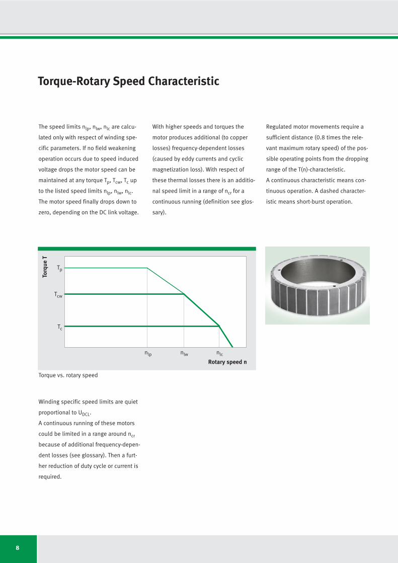
Torque-Rotary Speed Characteristic
The speed limits nlp, nlw, nlc are calcu -
lat ed only with respect of winding spe -
cific parameters. If no field weakening
operation occurs due to speed induced
voltage drops the motor speed can be
maintained at any torque Tp, Tcw, Tc up
to the listed speed limits nlp, nlw, nlc.
The motor speed finally drops down to
zero, depending on the DC link voltage.
With higher speeds and torques the
motor produces additional (to copper
losses) frequency-dependent losses
(caused by eddy currents and cyclic
magnetization loss). With respect of
these thermal losses there is an additio-
nal speed limit in a range of ncr for a
continuous running (definition see glos-
sary).
Regulated motor movements require a
sufficient distance (0.8 times the rele-
vant maximum rotary speed) of the pos-
sible operating points from the dropping
range of the T(n)-characteristic.
A continuous characteristic means con-
tinuous operation. A dashed character -
istic means short-burst operation.
Torq
ue T
Rotary speed n
Tc
nlp nlw nlc
Tcw
Tp
Torque vs. rotary speed
Winding specific speed limits are quiet
proportional to UDCL.
A continuous running of these motors
could be limited in a range around ncr
because of additional frequency-depen-
dent losses (see glossary). Then a furt-
her reduction of duty cycle or current is
required.
9
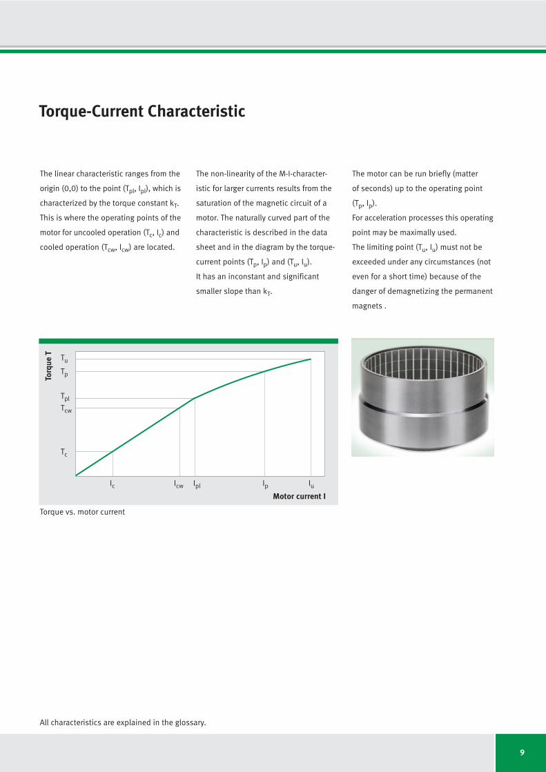
Torque-Current Characteristic
The linear characteristic ranges from the
origin (0,0) to the point (Tpl, Ipl), which is
characterized by the torque constant kT.
This is where the operating points of the
motor for uncooled operation (Tc, Ic) and
cooled operation (Tcw, Icw) are located.
The non-linearity of the M-I-character -
istic for larger currents results from the
saturation of the magnetic circuit of a
motor. The naturally curved part of the
characteristic is described in the data
sheet and in the diagram by the torque-
current points (Tp, Ip) and (Tu, Iu).
It has an inconstant and significant
smaller slope than kT.
The motor can be run briefly (matter
of seconds) up to the operating point
(Tp, Ip).
For acceleration processes this operating
point may be maximally used.
The limiting point (Tu, Iu) must not be
exceeded under any circumstances (not
even for a short time) because of the
danger of demagnetizing the permanent
magnets .
Torq
ue T
Motor current I
Tc
Icw IplIc Ip Iu
Tcw
Tpl
Tp
Tu
All characteristics are explained in the glossary.
Torque vs. motor current
10
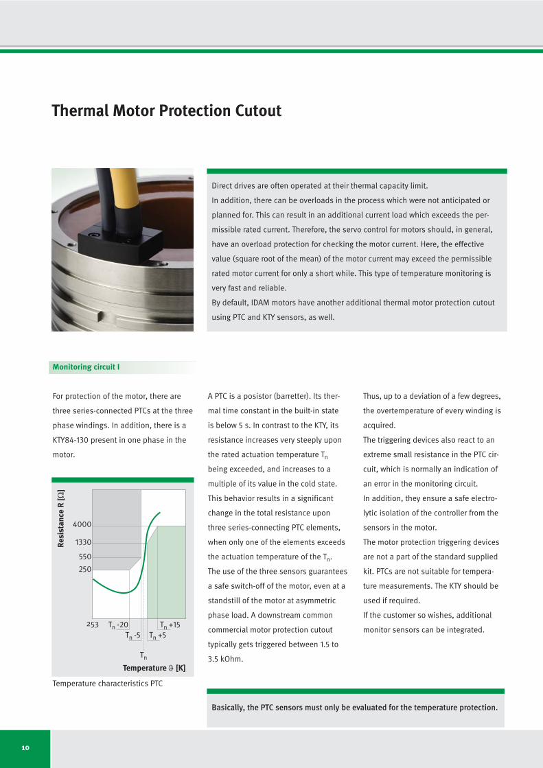
Thermal Motor Protection Cutout
Direct drives are often operated at their thermal capacity limit.
In addition, there can be overloads in the process which were not anticipated or
planned for. This can result in an additional current load which exceeds the per -
missible rated current. Therefore, the servo control for motors should, in general,
have an overload protection for checking the motor current. Here, the effective
value (square root of the mean) of the motor current may exceed the permissible
rated motor current for only a short while. This type of temperature monitoring is
very fast and reliable.
By default, IDAM motors have another additional thermal motor protection cutout
using PTC and KTY sensors, as well.
Monitoring circuit I
For protection of the motor, there are
three series-connected PTCs at the three
phase windings. In addition, there is a
KTY84-130 present in one phase in the
motor.
A PTC is a posistor (barretter). Its ther-
mal time constant in the built-in state
is below 5 s. In contrast to the KTY, its
resistance increases very steeply upon
the rated actuation temperature Tn
being exceeded, and increases to a
multiple of its value in the cold state.
This behavior results in a significant
change in the total resistance upon
three series-connecting PTC elements,
when only one of the elements exceeds
the actuation temperature of the Tn.
The use of the three sensors guarantees
a safe switch-off of the motor, even at a
standstill of the motor at asymmetric
phase load. A downstream common
commercial motor protection cutout
typically gets triggered between 1.5 to
3.5 kOhm.
Thus, up to a deviation of a few degrees,
the overtemperature of every winding is
acquired.
The triggering devices also react to an
extreme small resistance in the PTC cir-
cuit, which is normally an indication of
an error in the monitoring circuit.
In addition, they ensure a safe electro -
lytic isolation of the controller from the
sensors in the motor.
The motor protection triggering devices
are not a part of the standard supplied
kit. PTCs are not suitable for tempera -
ture measurements. The KTY should be
used if required.
If the customer so wishes, additional
monitor sensors can be integrated.
Resi
stan
ce R
[Ω]
250
550
1330
4000
Tn
Tn +5Tn -5Tn +15Tn -20253
Temperature ϑ [K]
Basically, the PTC sensors must only be evaluated for the temperature protection.
Temperature characteristics PTC
11
For protecting the motor from overtem-
perature, a cut-out limit is defined in
the controller. The sensor can only
measure in one phase.
U
PTC
PTC
KTY+
KTY-
V
W
+
Standard connection, PTC and KTY
While the motor is at standstill, constant
currents flow through the windings, whose
magnitude depends on the respective
pole position. As a result, the motor is
not heated homogeneously, which can
lead to overheating of windings that are
not being monitored.
The PTC and KTY sensors have a basic
insulation to the motor. They are not suit-
able for direct connection to PELV/SELV
circuits, according to DIN EN 50178.
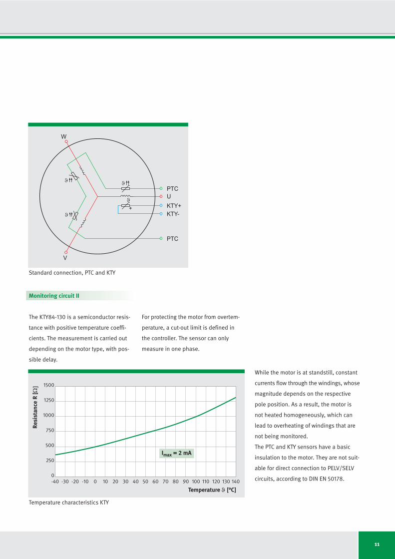
Monitoring circuit II
The KTY84-130 is a semiconductor resis-
tance with positive temperature coeffi-
cients. The measurement is carried out
depending on the motor type, with pos-
sible delay.
Temperature characteristics KTY
-40 -30 -20 -10 0 10 20 30 40 50 60 70 80 90 100 110 120 130 140
0
250
500
750
1000
1250
1500
Resi
stan
ce R
[Ω]
Temperature ϑ [°C]
Imax = 2 mA
12
Electrical Connections
The standard cable connections of the
IDAM motors are axial in nature.
Their relative position to the radiator
connections is defined in the drawings.
The cable length from the motor output
is 1000 mm, or according to the cus -
tomer’s wishes. The cross-section of the
power connection cable is dependent
upon the rated motor current and docu-
mented in the catalog drawing. By de-
fault, the dimensioning is done on the
rated current Icw at Plw (cooled). The
motor cables are available from 4G0.75
mm2 onwards. The sensor cable 0.14
mm2 (d = 6.0 mm; rd = 45 mm; rs = 24
mm; m = 67 g/m) makes temperature
monitoring with PTC and KTY possible.
The design of the cable ends is open
Pin layout
Motor
U Phase U
VV Phase V
WWW Phase W
GNYE PE
BK Shield
Sensor
WH PTC
BN PTC
GN + KTY
YE - KTY
with strand end-sleeves. The cables
used are UL-approved and can with-
stand drag chains.
The axial cable outlets for the winding
WM are depicted and dimensioned in
the data sheets (page 22 onwards).
From motor currents above 70 A
onwards, the cable outlets are matched
in an application-specific manner.
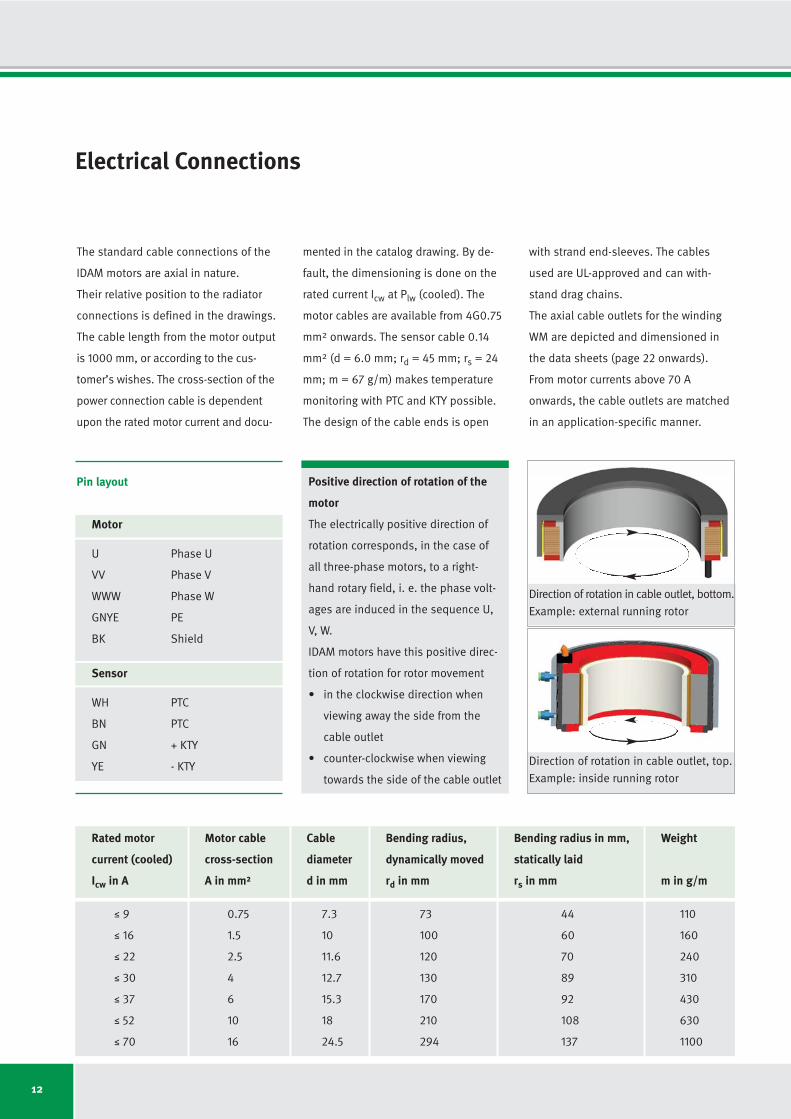
Positive direction of rotation of the
motor
The electrically positive direction of
rotation corresponds, in the case of
all three-phase motors, to a right-
hand rotary field, i. e. the phase volt -
ages are induced in the sequence U,
V, W.
IDAM motors have this positive direc-
tion of rotation for rotor movement
• in the clockwise direction when
viewing away the side from the
cable outlet
• counter-clockwise when viewing
towards the side of the cable outlet
Rated motor Motor cable Cable Bending radius, Bending radius in mm, Weight
current (cooled) cross-section diameter dynamically moved statically laid
Icw in A A in mm² d in mm rd in mm rs in mm m in g/m
M 9 0.75 7.3 73 44 110
M 16 1.5 10 100 60 160
M 22 2.5 11.6 120 70 240
M 30 4 12.7 130 89 310
M 37 6 15.3 170 92 430
M 52 10 18 210 108 630
M 70 16 24.5 294 137 1100
Direction of rotation in cable outlet, top.
Example: inside running rotor
Direction of rotation in cable outlet, bottom.
Example: external running rotor
13
Commutation
Insulation Strength
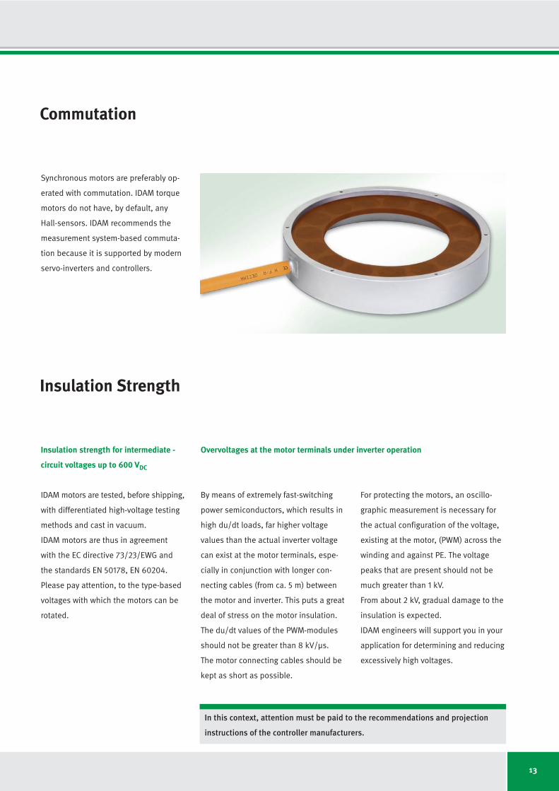
Synchronous motors are preferably op -
erated with commutation. IDAM torque
motors do not have, by default, any
Hall-sensors. IDAM recommends the
measurement system-based commuta -
tion because it is supported by modern
servo-inverters and controllers.
Insulation strength for intermediate -
circuit voltages up to 600 VDC
IDAM motors are tested, before shipping,
with differentiated high-voltage testing
methods and cast in vacuum.
IDAM motors are thus in agreement
with the EC directive 73/23/EWG and
the standards EN 50178, EN 60204.
Please pay attention, to the type-based
voltages with which the motors can be
rotated.
By means of extremely fast-switching
power semiconductors, which results in
high du/dt loads, far higher voltage
values than the actual inverter voltage
can exist at the motor terminals, espe -
cially in conjunction with longer con-
necting cables (from ca. 5 m) between
the motor and inverter. This puts a great
deal of stress on the motor insulation.
The du/dt values of the PWM-modules
should not be greater than 8 kV/μs.
The motor connecting cables should be
kept as short as possible.
For protecting the motors, an oscillo-
graphic measurement is necessary for
the actual configuration of the voltage,
existing at the motor, (PWM) across the
winding and against PE. The voltage
peaks that are present should not be
much greater than 1 kV.
From about 2 kV, gradual damage to the
insulation is expected.
IDAM engineers will support you in your
application for determining and reducing
excessively high voltages.
Overvoltages at the motor terminals under inverter operation
In this context, attention must be paid to the recommendations and projection
instructions of the controller manufacturers.
14
Cooling and the Cooling Circuits
The power loss that occurs during the
operation of the motor gets transferred
to the machine through the motor as -
semblies. This heat distribution through
convection, conduction, and radiation
can be purposefully influenced and con-
trolled by a constructive design of the
overall system.
The nominal torques of the motors are
approx. 50% higher with liquid cooling
than in uncooled operation. Depending
on the mounting space, accuracy require -
ments, and the necessity for cooling,
the motors should be designed and
integrated into the machine design.
In production machines with a high
rating or devices with very high dyna-
mics, and hence higher bearing loading,
it is preferable to work with cooling.
If a complete thermal de-coupling of the
motor and the machine is required (for
example, to avoid thermal deformation
of the machine construction in precision
machines), a precision cooling is addi-
tionally necessary. The actual cooling is
then called the main cooling or power
cooling.
The cooling of the motors is designed
as jacket cooling, which the user must
connect to the cooling circuit of a cool -
ing assembly. The cooling jacket is op-
tionally supplied as a part of the motor,
or is already an integral part of the ma-
chine construction for the customer.
The cooling medium goes from the inlet
to the outlet through holes in the cool -
ing fins at different levels.
The inlet and outlet can be connected
at will to the two connections. The flow
area is sealed to the outside with O-rings.
If water is used as the cooling medium,
additives that prevent corrosion and
biological deposits in the cooling circuit
should be used.
Power loss and lost heat
Apart from the power loss, which is described by the motor constant km additional
frequency-dependent losses occur in the motor, especially at high control frequen-
cies (in the range from 150 - 200 Hz). These losses contribute jointly to the heating
of the motor and the system assemblies.
At low control frequencies of the motors, the following applies: motors with a high
km produce, as compared to motors with a lower km, less power loss.
For the unrestricted thermal examination of the motor, bearing, and system assem-
blies, IDAM offers comprehensive thermal simulations.
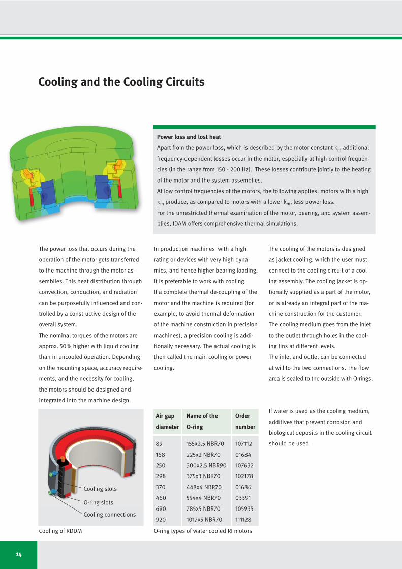
Cooling connections
Cooling slots
O-ring slots
Cooling of RDDM
Air gap Name of the Order
diameter O-ring number
89 155x2.5 NBR70 107112
168 225x2 NBR70 01684
250 300x2.5 NBR90 107632
298 375x3 NBR70 102178
370 448x4 NBR70 01686
460 554x4 NBR70 03391
690 785x5 NBR70 105935
920 1017x5 NBR70 111128
O-ring types of water cooled RI motors

15
Dependency of the Rating Data on the Supply Temperature
The continuous current Icw indicated in
the data sheet for water cooled opera-
tion can be achieved at a rated supply
temperature ϑnV of 25 °C. Higher supply
temperatures ϑV result in a reduction of
the cooling performance and therefore
also the nominal current. The reduced
continuous current Ic red can be calcu -
lated from the following quadratic equa-
tion:
Relative continuous current Ic red / Icw vs. supply temperature ϑV (ϑnV = 25 °C)
10 20 30 40 50 60 70
Supply temperature ϑ [°C]
Rati
o I c
red
/ I c
w[%
] 120
100
80
60
40
20
0
Ic red Reduced continuous current [A]
Icw Continuous current, cooled
at ϑnV [A]
ϑV Current supply temperature [°C]
ϑnV Rated supply temperature [°C]
ϑmax Maximum permissible winding
temperature [°C]
(applies to a constant motor current)
Ic red
Icw
ϑmax - ϑV
ϑmax - ϑnV=
16
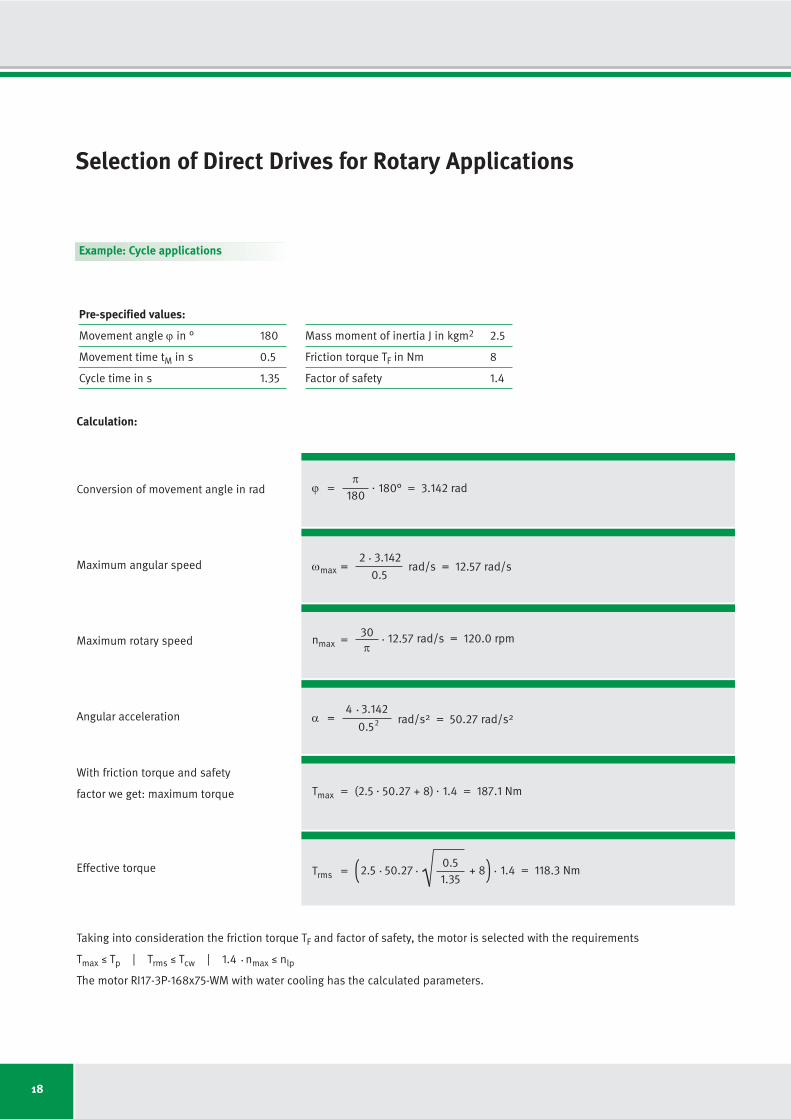
Selection of Direct Drives for Rotary Applications
Cycle applications
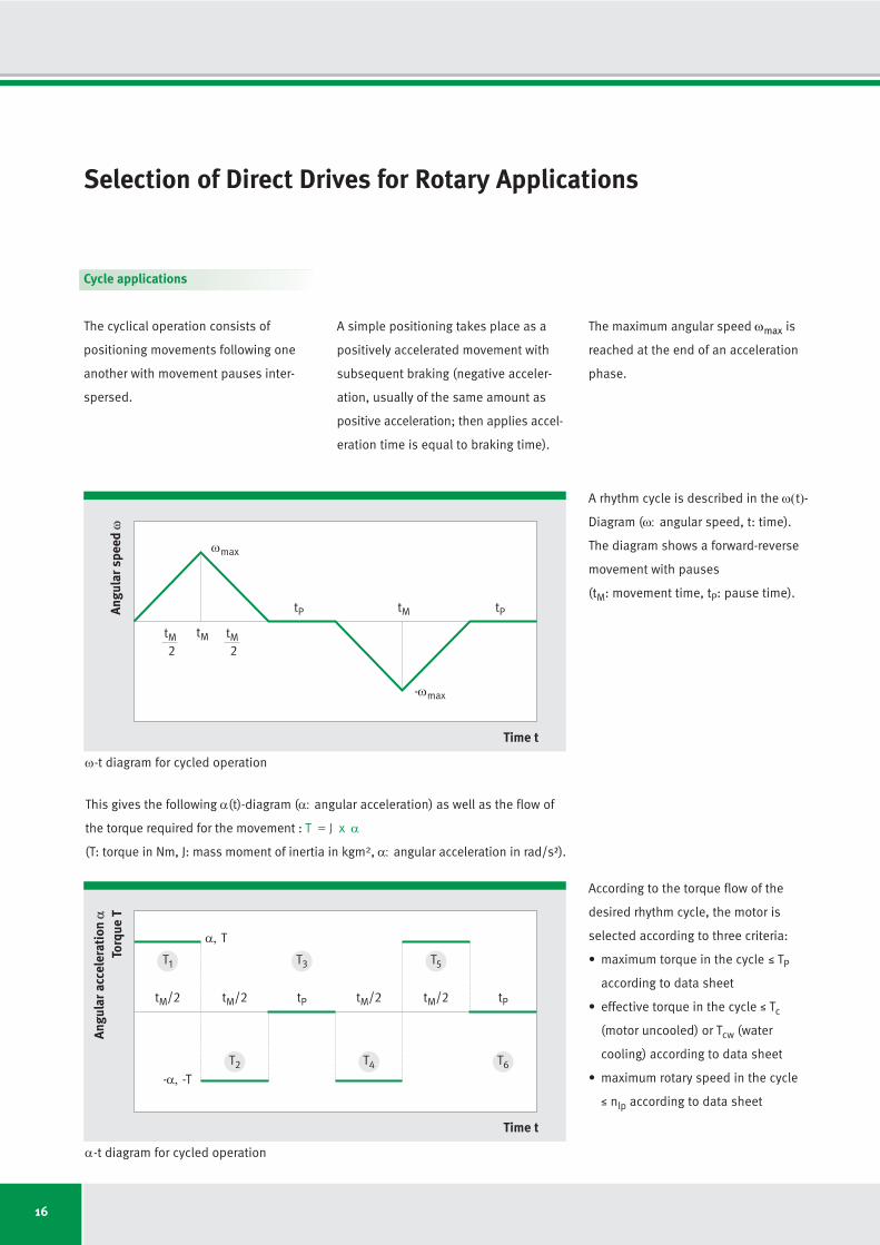
The cyclical operation consists of
positioning movements following one
an other with movement pauses inter -
spersed.
Angu
lar s
peed
ω
Time t
ωmax
tMtM2
tMtP tP
-ωmax
Angu
lar a
ccel
erat
ion
αTo
rque
T
Time t
α, T
-α, -T
tM/2 tM/2 tP tM/2 tM/2 tP
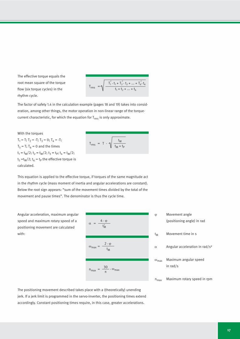
This gives the following α(t)-diagram (α: angular acceleration) as well as the flow of
the torque required for the movement : T = J x α
(T: torque in Nm, J: mass moment of inertia in kgm2, α: angular acceleration in rad/s²).
A simple positioning takes place as a
positively accelerated movement with
subsequent braking (negative acceler -
ation, usually of the same amount as
positive acceleration; then applies ac cel-
eration time is equal to braking time).
A rhythm cycle is described in the ω(t)-
Diagram (ω: angular speed, t: time).
The diagram shows a forward-reverse
movement with pauses
(tM: movement time, tP: pause time).
According to the torque flow of the
desired rhythm cycle, the motor is
selected according to three criteria:
• maximum torque in the cycle M TP
according to data sheet
• effective torque in the cycle M Tc
(motor uncooled) or Tcw (water
cooling) according to data sheet
• maximum rotary speed in the cycle
M nlp according to data sheet
T1
T2
T3
T4
T5
T6
tM2
ω-t diagram for cycled operation
α-t diagram for cycled operation
The maximum angular speed ωmax is
reached at the end of an acceleration
phase.
17
The effective torque equals the
root mean square of the torque
flow (six torque cycles) in the
rhythm cycle.
Trms
T1
t1
+=
2
. T2
t2
+ ... +2
. .T6
t6
2
t1
+ t2
+ ... + t6
Trms
tM= T .
tM + tP
α4 ϕ
=tM
With the torques
T1
= T; T2
= -T; T3
= 0; T4
= -T;
T5
= T; T6
= 0 and the times
t1
= tM/2; t2
= tM/2; t3
= tP; t4
= tM/2;
t5
=tM/2; t6
= tP the effective torque is
calculated.
Angular acceleration, maximum angular
speed and maximum rotary speed of a
positioning movement are calculated
with:
This equation is applied to the effective torque, if torques of the same magnitude act
in the rhythm cycle (mass moment of inertia and angular accelerations are constant).
Below the root sign appears: “sum of the movement times divided by the total of the
movement and pause times”. The denominator is thus the cycle time.
The positioning movement described takes place with a (theoretically) unending
jerk. If a jerk limit is programmed in the servo-inverter, the positioning times extend
accordingly. Constant positioning times require, in this case, greater accelerations.
.2
ωmax2 ϕ
=tM
.
nmax30
=π
. ωmax
ϕ Movement angle
(positioning angle) in rad
tM Movement time in s
α Angular acceleration in rad/s²
ωmax Maximum angular speed
in rad/s
nmax Maximum rotary speed in rpm
The factor of safety 1.4 in the calculation example (pages 18 and 19) takes into consid -
eration, among other things, the motor operation in non-linear range of the torque-
current characteristic, for which the equation for Trms is only approximate.
18
Example: Cycle applications
Pre-specified values:
Movement angle ϕ in ° 180
Movement time tM in s 0.5
Cycle time in s 1.35
Mass moment of inertia J in kgm22.5
Friction torque TF in Nm 8
Factor of safety 1.4
ϕπ
=180
180° = 3.142 radConversion of movement angle in rad
Maximum angular speed
Maximum rotary speed
Angular acceleration
With friction torque and safety
factor we get: maximum torque
Effective torque
Taking into consideration the friction torque TF and factor of safety, the motor is selected with the requirements
Tmax M Tp | Trms M Tcw | 1.4 nmax M nlp
The motor RI17-3P-168x75-WM with water cooling has the calculated parameters.
.
ωmax2 3.142
= rad/s = 12.57 rad/s0.5
.
nmax30
=π
. 12.57 rad/s = 120.0 rpm
Tmax = (2.5 50.27 + 8) 1.4 = 187.1 Nm. .
Calculation:
α4 3.142
= rad/s2 = 50.27 rad/s20.5
.
Trms0.5
= . ..
.
1.35
2.5 50.27 + 8 1.4 = 118.3 Nm( )
Selection of Direct Drives for Rotary Applications
2
19
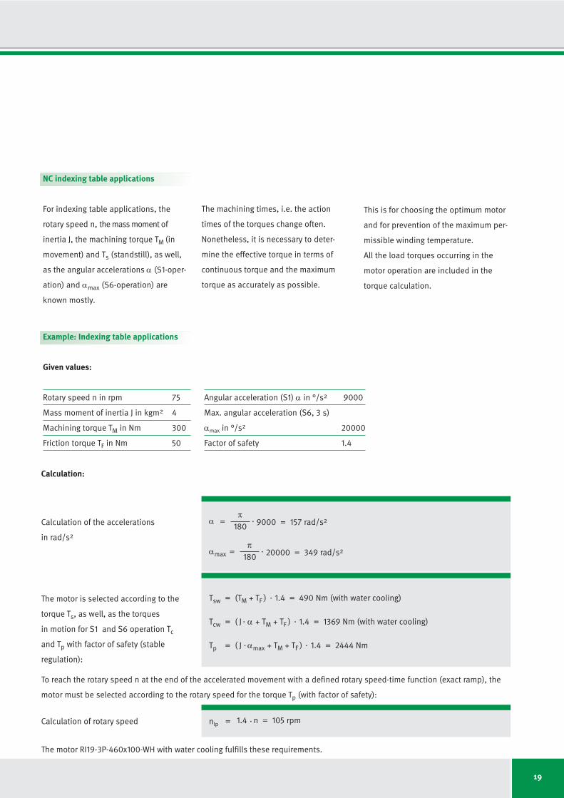
NC indexing table applications
For indexing table applications, the
rotary speed n, the mass moment of
inertia J, the machining torque TM (in
movement) and Ts (standstill), as well,
as the angular accelerations α (S1-oper -
ation) and αmax (S6-operation) are
known mostly.
The machining times, i.e. the action
times of the torques change often.
Nonetheless, it is necessary to deter-
mine the effective torque in terms of
continuous torque and the maximum
torque as accurately as possible.
Example: Indexing table applications
Given values:
Rotary speed n in rpm 75
Mass moment of inertia J in kgm24
Machining torque TM in Nm 300
Friction torque TF in Nm 50
Angular acceleration (S1) α in °/s29000
Max. angular acceleration (S6, 3 s)
αmax in °/s220000
Factor of safety 1.4
The motor RI19-3P-460x100-WH with water cooling fulfills these requirements.
απ
=180
9000 = 157 rad/s2.
αmaxπ
=180
20000 = 349 rad/s2.
Tsw = (TM + TF ) 1.4 = 490 Nm (with water cooling).
Tcw = ( J α + TM + TF ) 1.4 = 1369 Nm (with water cooling). .
Tp = ( J αmax + TM + TF ) 1.4 = 2444 Nm. .
Calculation of the accelerations
in rad/s2
The motor is selected according to the
torque Ts, as well, as the torques
in motion for S1 and S6 operation Tc
and Tp with factor of safety (stable
regulation):
To reach the rotary speed n at the end of the accelerated movement with a defined rotary speed-time function (exact ramp), the
motor must be selected according to the rotary speed for the torque Tp (with factor of safety):
nlpCalculation of rotary speed = .1.4 n = 105 rpm
Calculation:
This is for choosing the optimum motor
and for prevention of the maximum per-
missible winding temperature.
All the load torques occurring in the
motor operation are included in the
torque calculation.
20
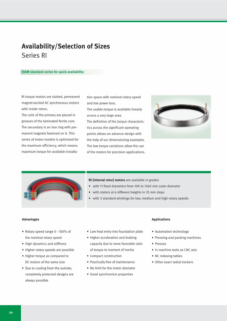
RI (internal rotor) motors are available in grades
• with 11 fixed diameters from 100 to 1260 mm outer diameter
• with stators at 6 different heights in 25 mm steps
• with 3 standard windings for low, medium and high rotary speeds
Advantages
• Rotary speed range 0 - 100% of
the nominal rotary speed
• High dynamics and stiffness
• Higher rotary speeds are possible
• Higher torque as compared to
DC motors of the same size
• Due to cooling from the outside,
completely protected designs are
always possible
• Low heat entry into foundation plate
• Higher acceleration and braking
capacity due to more favorable ratio
of torque to moment of inertia
• Compact construction
• Practically free of maintenance
• No limit for the motor diameter
• Good synchronism properties
Applications
• Automation technology
• Pressing and packing machines
• Presses
• In machine tools as CNC axis
• NC indexing tables
• Other exact radial trackers
Availability/Selection of Sizes Series RI
RI torque motors are slotted, permanent
magnet-excited AC synchronous motors
with inside rotors.
The coils of the primary are placed in
grooves of the laminated ferrite core.
The secondary is an iron ring with per-
manent magnets fastened on it. This
series of motor models is optimized for
the maximum efficiency, which means:
maximum torque for available installa -
tion space with nominal rotary speed
and low power loss.
The usable torque is available linearly
across a very large area.
The definition of the torque characteris-
tics across the significant operating
points allows an advance design with
the help of our dimensioning examples.
The low torque variations allow the use
of the motors for precision applications.
IDAM standard series for quick availability
21
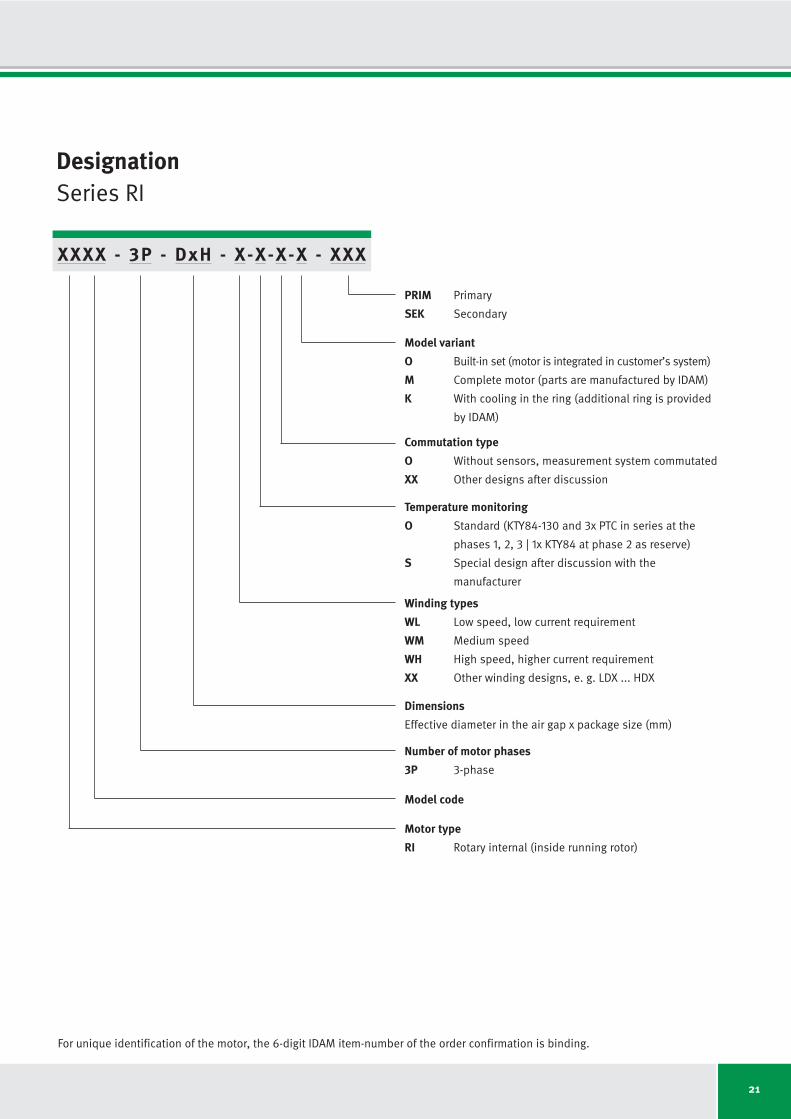
DesignationSeries RI
XXXX - 3P - DxH - X-X-X-X - XXX
PRIM Primary
SEK Secondary
Model variant
O Built-in set (motor is integrated in customer’s system)
M Complete motor (parts are manufactured by IDAM)
K With cooling in the ring (additional ring is provided
by IDAM)
Commutation type
O Without sensors, measurement system commutated
XX Other designs after discussion
Winding types
WL Low speed, low current requirement
WM Medium speed
WH High speed, higher current requirement
XX Other winding designs, e. g. LDX ... HDX
Dimensions
Effective diameter in the air gap x package size (mm)
Number of motor phases
3P 3-phase
Model code
Motor type
RI Rotary internal (inside running rotor)
Temperature monitoring
O Standard (KTY84-130 and 3x PTC in series at the
phases 1, 2, 3 | 1x KTY84 at phase 2 as reserve)
S Special design after discussion with the
manufacturer
For unique identification of the motor, the 6-digit IDAM item-number of the order confirmation is binding.
22
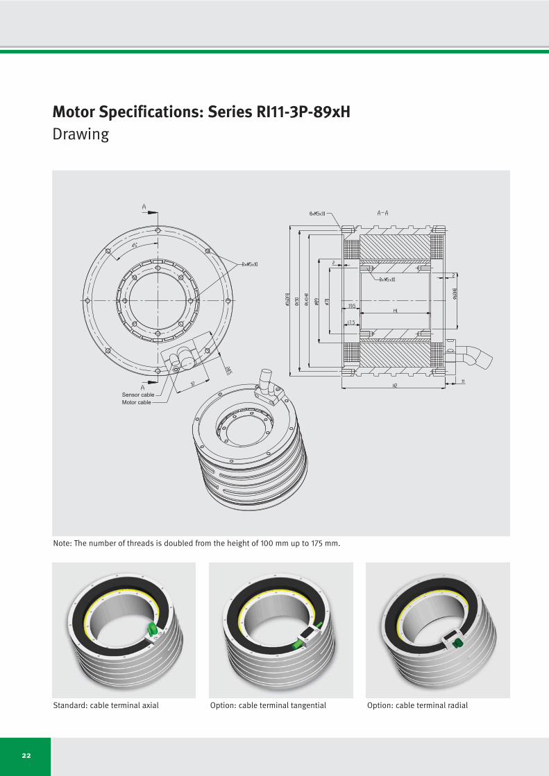
Motor Specifications: Series RI11-3P-89xHDrawing
Sensor cable
Motor cable
Standard: cable terminal axial Option: cable terminal tangential Option: cable terminal radial
Note: The number of threads is doubled from the height of 100 mm up to 175 mm.

23
Motor Specifications: Series RI11-3P-89xHIndependent of winding
Motor specifications Symbol Unit RI11-3P- RI11-3P- RI11-3P- RI11-3P- RI11-3P- RI11-3P- RI11-3P-
89x25 89x50 89x75 89x100 89x125 89x150 89x175
Number of pole pairs P
Maximum operating voltage UDCL VDC
Ultimate torque at Iu Tu Nm
Peak torque (saturation range) at Ip Tp Nm
Peak torque (linear range) at Ipl Tpl Nm
Continuous torque (water cooled) at Icw Tcw Nm
Continuous torque (not cooled) at Ic Tc Nm
Stall torque (water cooled) at Isw Tsw Nm
Stall torque (not cooled) at Is Ts Nm
Ripple torque (cogging) at I = 0 Tr Nm
Power loss (copper) at Tp (statical at 25 °C) Plp W
Power loss (copper) at Tpl (statical at 25 °C) Plpl W
Power loss (copper) at Tcw (statical at 100 °C) Plw W
Power loss (copper) at Tc (statical at 25 °C) Plc W
Thermical resistance (water cooled) Rth K/W
Motor constant (at 25 °C; valid up to Ipl) km Nm/√W
Water flow (cooling) dV/dt l/min
Water temperature difference (cooling) Δϑ K
Mechanical interface Symbol Unit RI11-3P- RI11-3P- RI11-3P- RI11-3P- RI11-3P- RI11-3P- RI11-3P-
89x25 89x50 89x75 89x100 89x125 89x150 89x175
Height of rotor H1
mm
Height of stator H2
mm
Mass of rotor m1
kg
Mass of stator m2
kg
Inertia of rotor J kgm2
11
600
32.4
23.5
17.2
12.6
4.9
8.9
3.4
0.07
1130
442
304
35
0.329
0.82
0.87
5.00
25.0
70.0
0.5
5.3
0.00075
51.0
90.0
1.1
7.4
0.0015
75.0
110.0
1.6
9.4
0.00225
101.0
140.0
2.2
11.9
0.0030
125.0
165.0
2.7
14.3
0.00375
151.0
190.0
3.2
16.5
0.0045
175.0
215.0
3.8
18.8
0.00525
11
600
64.9
46.9
34.5
29.2
11.0
20.8
7.8
0.14
1669
652
609
66
0.164
1.35
1.74
5.00
11
600
97.3
70.4
51.7
46.7
17.1
33.2
12.2
0.21
2207
862
913
94
0.110
1.76
2.61
5.00
11
600
130
94
69
64
23
46
16
0.3
2745
1072
1218
120
0.082
2.11
3.48
5.00
11
600
162
117
86
82
28
59
20
0.4
3283
1283
1522
140
0.066
2.41
4.35
5.00
11
600
195
141
103
100
33
71
24
0.4
3821
1493
1826
155
0.055
2.68
5.22
5.00
11
600
227
164
121
118
38
84
27
0.5
4360
1703
2131
171
0.047
2.93
6.09
5.00
Subject to modification without previous notice. • Tolerance range for values: ±5% • Tolerance range for value “power loss”: ±10%
IDAM will provide additional specifications and drawings per customer request. IDAM recommends that all motor applications be reviewed by an IDAM specialist.

7.30
5.97
128
234
373
380
582
829
818
11.43
71.9
19.1
11.3
7.1
6.4
2.3
4.5
1.7
130
100
RI11-3P-
89x75-
WL
24
Winding specific speed limits are quiet
proportional to UDCL.
A continuous running of these motors
could be limited in a range around ncr
because of additional frequency-depen-
dent losses (see glossary).
Then a further reduction of duty cycle or
current is required.
2.43
1.99
531
922
1217
1253
2065
2634
818
5.85
24.0
19.1
11.3
7.1
5.2
2.0
3.7
1.4
130
100
1.22
0.99
1184
1955
2497
2610
4238
5329
818
1.46
6.0
38.1
22.7
14.2
10.3
4.0
7.3
2.8
130
100
0.61
0.50
2471
4023
5057
5315
8595
10725
818
0.37
1.5
76.2
45.4
28.4
20.6
7.9
14.6
5.6
130
100
4.86
3.98
232
397
581
599
933
1274
818
8.64
47.9
19.1
11.3
7.1
6.0
2.3
4.3
1.6
130
100
2.43
1.99
564
881
1213
1281
1948
2600
818
2.16
12.0
38.1
22.7
14.2
12.0
4.5
8.5
3.2
130
100
1.22
0.99
1211
1848
2477
2635
3984
5254
818
0.54
3.0
76.2
45.4
28.4
23.9
9.0
17.0
6.4
130
100
RI11-3P-
89x25-
WL
Symbol
kT
ku
nlp
nlw
nlc
nlp
nlw
nlc
ncr
R25
L
Iu
Ip
Ipl
Icw
Ic
Isw
Is
ϑ
ϑ
Unit
Nm/Arms
Vs/rad
rpm
rpm
rpm
rpm
rpm
rpm
rpm
Ω
mH
Arms
Arms
Arms
Arms
Arms
Arms
Arms
°C
°C
RI11-3P-
89x25-
WM
RI11-3P-
89x25-
WH
RI11-3P-
89x50-
WL
RI11-3P-
89x50-
WM
RI11-3P-
89x50-
WH
Winding Configuration: Series RI11-3P-89
Winding dependent specifications
Torque constant
Back EMF constant
Limiting speed at Ip and UDCL = 280 V
Limiting speed at Icw and UDCL = 280 V
Limiting speed at Ic and UDCL = 280 V
Limiting speed at Ip and UDCL = 600 V
Limiting speed at Icw and UDCL = 600 V
Limiting speed at Ic and UDCL = 600 V
Limiting speed for continuous running*
Electrical resistance, phase to phase (25 °C)
Inductance, phase to phase
Ultimate current
Peak current (saturation range)
Peak current (linear range)
Continuous current (water cooled)
Continuous current (not cooled)
Stall current at zero speed (water cooled)
Stall current at zero speed (not cooled)
Maximum winding temperature
Interrupting sensor temperature
*See glossary • Subject to modification without previous notice. • Tolerance range for values: ±5% • Tolerance range for value “resistance”: ±10% • Tolerance range for value “inductance”: ±15%
Torq
ue T
Rotary speed n
Tc
nlp nlw nlc
Tcw
Tp

Symbol
kT
ku
nlp
nlw
nlc
nlp
nlw
nlc
ncr
R25
L
Iu
Ip
Ipl
Icw
Ic
Isw
Is
ϑ
ϑ
3.65
2.98
356
549
792
837
1239
1705
818
2.86
18.0
38.1
22.7
14.2
12.8
4.7
9.1
3.3
130
100
RI11-3P-
89x75-
WM
25
9.73
7.96
72
154
270
269
413
608
-
14.21
95.9
19.1
11.3
7.1
6.6
2.4
4.7
1.7
130
100
4.86
3.98
251
388
584
615
898
1263
818
3.55
24.0
38.1
22.7
14.2
13.3
4.7
9.4
3.4
130
100
2.43
1.99
579
850
1212
1294
1867
2572
818
0.90
6.0
76.2
45.4
28.4
26.4
9.5
18.7
6.7
130
100
12.16
9.95
34
107
210
201
314
477
-
17.00
119.9
19.1
11.3
7.1
6.8
2.3
4.8
1.7
130
100
6.08
4.97
187
294
462
481
698
999
818
4.25
30.0
38.1
22.7
14.2
13.6
4.7
9.6
3.3
130
100
3.04
2.49
452
660
965
1025
1465
2043
818
1.07
7.5
76.2
45.4
28.4
27.0
9.3
19.2
6.6
130
100
14.59
11.94
4
75
171
155
249
390
-
19.79
143.8
19.1
11.3
7.1
6.9
2.3
4.9
1.6
130
100
7.30
5.97
143
232
381
391
567
824
818
4.95
36.0
38.1
22.7
14.2
13.8
4.6
9.8
3.2
130
100
3.65
2.98
367
536
802
846
1201
1692
818
1.25
9.0
76.2
45.4
28.4
27.4
9.1
19.5
6.5
130
100
17.02
13.93
-
51
142
122
202
328
-
22.57
167.8
19.1
11.3
7.1
7.0
2.2
4.9
1.6
130
100
8.51
6.96
111
188
323
327
475
699
-
5.64
41.9
38.1
22.7
14.2
13.9
4.5
9.9
3.2
130
100
4.26
3.48
306
448
684
718
1015
1442
818
1.42
10.5
76.2
45.4
28.4
27.7
9.0
19.7
6.4
130
100
RI11-3P-
89x100-
WL
RI11-3P-
89x100-
WM
RI11-3P-
89x100-
WH
RI11-3P-
89x125-
WL
RI11-3P-
89x125-
WM
RI11-3P-
89x125-
WH
RI11-3P-
89x150-
WL
RI11-3P-
89x150-
WM
RI11-3P-
89x150-
WH
RI11-3P-
89x175-
WL
RI11-3P-
89x175-
WM
RI11-3P-
89x175-
WH
Torq
ue T
Motor current I
Tc
Icw IplIc Ip Iu
Tcw
Tpl
Tp
Tu
1.82
1.49
790
1174
1630
1741
2555
3460
818
0.72
4.5
76.2
45.4
28.4
25.5
9.3
18.1
6.6
130
100
RI11-3P-
89x75-
WH
26
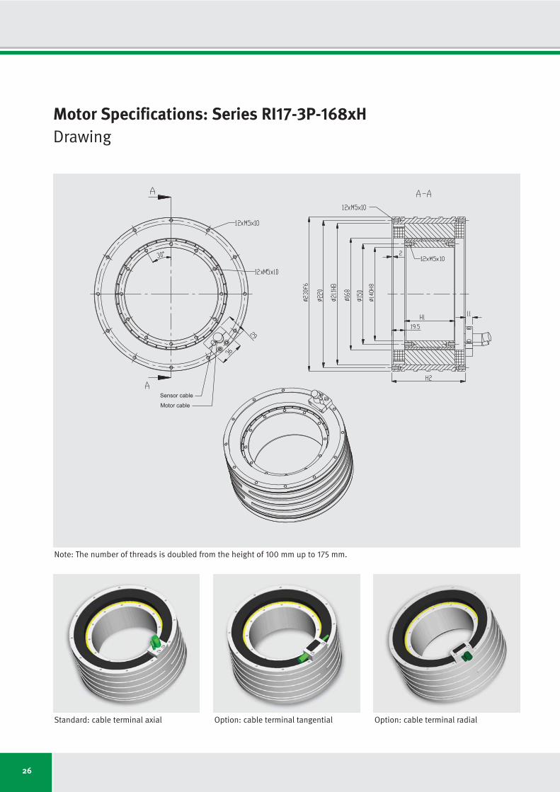
Motor Specifications: Series RI17-3P-168xHDrawing
Sensor cable
Motor cable
Standard: cable terminal axial Option: cable terminal tangential Option: cable terminal radial
Note: The number of threads is doubled from the height of 100 mm up to 175 mm.

27
Motor specifications Symbol Unit RI17-3P- RI17-3P- RI17-3P- RI17-3P- RI17-3P- RI17-3P- RI17-3P-
168x25 168x50 168x75 168x100 168x125 168x150 168x175
Number of pole pairs P
Maximum operating voltage UDCL VDC
Ultimate torque at Iu Tu Nm
Peak torque (saturation range) at Ip Tp Nm
Peak torque (linear range) at Ipl Tpl Nm
Continuous torque (water cooled) at Icw Tcw Nm
Continuous torque (not cooled) at Ic Tc Nm
Stall torque (water cooled) at Isw Tsw Nm
Stall torque (not cooled) at Is Ts Nm
Ripple torque (cogging) at I = 0 Tr Nm
Power loss (copper) at Tp (statical at 25 °C) Plp W
Power loss (copper) at Tpl (statical at 25 °C) Plpl W
Power loss (copper) at Tcw (statical at 100 °C) Plw W
Power loss (copper) at Tc (statical at 25 °C) Plc W
Thermical resistance (water cooled) Rth K/W
Motor constant (at 25 °C; valid up to Ipl) km Nm/√W
Water flow (cooling) dV/dt l/min
Water temperature difference (cooling) Δϑ K
Mechanical interface Symbol Unit RI17-3P- RI17-3P- RI17-3P- RI17-3P- RI17-3P- RI17-3P- RI17-3P-
168x25 168x50 168x75 168x100 168x125 168x150 168x175
Height of rotor H1
mm
Height of stator H2
mm
Mass of rotor m1
kg
Mass of stator m2
kg
Inertia of rotor J kgm2
17
600
110
93
65
36
16
25
11
0.3
2909
1136
455
66
0.220
1.92
1.30
5.00
25.0
70.0
1.2
7.5
0.007
51.0
90.0
2.4
10.4
0.014
75.0
110.0
3.6
13.3
0.021
101.0
140.0
4.8
16.8
0.028
125.0
165.0
6.0
20.1
0.035
151.0
190.0
7.2
23.3
0.042
175.0
215.0
8.4
26.6
0.049
17
600
220
186
129
85
36
60
25
0.6
4173
1630
911
124
0.110
3.20
2.60
5.00
17
600
327
276
192
135
56
96
39
0.8
5438
2124
1366
178
0.073
4.17
3.90
5.00
17
600
436
369
256
187
75
133
53
1.1
6702
2618
1822
227
0.055
5.00
5.21
5.00
17
600
539
456
317
238
92
169
65
1.4
7967
3112
2277
264
0.044
5.68
6.51
5.00
17
600
647
547
380
290
108
206
77
1.6
9232
3606
2733
293
0.037
6.33
7.81
5.00
17
600
755
639
443
343
124
243
88
1.9
10496
4100
3188
323
0.031
6.92
9.11
5.00
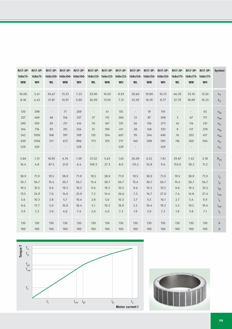
Motor Specifications: Series RI17-3P-168xHIndependent of winding
Subject to modification without previous notice. • Tolerance range for values: ±5% • Tolerance range for value “power loss”: ±10%
IDAM will provide additional specifications and drawings per customer request. IDAM recommends that all motor applications be reviewed by an IDAM specialist.

28
6.73
5.51
168
365
438
523
857
966
529
8.22
21.9
19.5
15.4
9.6
5.3
2.3
3.8
1.6
130
100
3.37
2.75
484
810
915
1162
1790
1971
529
2.06
5.5
38.9
30.7
19.2
10.7
4.6
7.6
3.3
130
100
1.82
1.49
1000
1564
1723
2238
3372
3673
529
0.60
1.6
71.9
56.7
35.5
19.7
8.5
14.0
6.1
130
100
13.47
11.02
44
151
205
232
391
467
-
11.80
43.7
19.5
15.4
9.6
6.3
2.6
4.5
1.9
130
100
6.73
5.51
212
368
443
555
844
965
529
2.95
10.9
38.9
30.7
19.2
12.6
5.3
8.9
3.8
130
100
3.65
2.98
473
733
845
1095
1611
1811
529
0.87
3.2
71.9
56.7
35.5
23.2
9.8
16.5
6.9
130
100
RI17-3P-
168x25-
WL
RI17-3P-
168x25-
WM
RI17-3P-
168x25-
WH
RI17-3P-
168x50-
WL
RI17-3P-
168x50-
WM
RI17-3P-
168x50-
WH
Winding Configuration: Series RI17-3P-168xH
Winding dependent specifications
Torque constant
Back EMF constant
Limiting speed at Ip and UDCL = 280 V
Limiting speed at Icw and UDCL = 280 V
Limiting speed at Ic and UDCL = 280 V
Limiting speed at Ip and UDCL = 600 V
Limiting speed at Icw and UDCL = 600 V
Limiting speed at Ic and UDCL = 600 V
Limiting speed for continuous running*
Electrical resistance, phase to phase (25 °C)
Inductance, phase to phase
Ultimate current
Peak current (saturation range)
Peak current (linear range)
Continuous current (water cooled)
Continuous current (not cooled)
Stall current at zero speed (water cooled)
Stall current at zero speed (not cooled)
Maximum winding temperature
Interrupting sensor temperature
Symbol
kT
ku
nlp
nlw
nlc
nlp
nlw
nlc
ncr
R25
L
Iu
Ip
Ipl
Icw
Ic
Isw
Is
ϑ
ϑ
*See glossary • Subject to modification without previous notice. • Tolerance range for values: ±5% • Tolerance range for value “resistance”: ±10% • Tolerance range for value “inductance”: ±15%
Unit
Nm/Arms
Vs/rad
rpm
rpm
rpm
rpm
rpm
rpm
rpm
Ω
mH
Arms
Arms
Arms
Arms
Arms
Arms
Arms
°C
°C
Winding specific speed limits are quiet
proportional to UDCL.
A continuous running of these motors
could be limited in a range around ncr
because of additional frequency-depen-
dent losses (see glossary).
Then a further reduction of duty cycle or
current is required.
Torq
ue T
Tc
Tcw
Tp
20.00
16.36
-
83
130
134
242
304
-
15.37
65.6
19.5
15.4
9.6
6.8
2.8
4.8
2.0
130
100
RI17-3P-
168x75-
WL
Symbol
kT
ku
nlp
nlw
nlc
nlp
nlw
nlc
ncr
R25
L
Iu
Ip
Ipl
Icw
Ic
Isw
Is
ϑ
ϑ
29
26.67
21.81
-
48
92
83
168
221
-
18.95
87.5
19.5
15.4
9.6
7.0
2.8
5.0
2.0
130
100
13.33
10.91
71
156
211
251
391
472
-
4.74
21.9
38.9
30.7
19.2
14.0
5.7
10.0
4.0
130
100
7.22
5.90
209
337
414
524
769
896
529
1.39
6.4
71.9
56.7
35.5
25.9
10.4
18.4
7.4
130
100
33.00
26.99
-
27
70
51
125
173
-
22.52
109.3
19.5
15.4
9.6
7.2
2.8
5.1
2.0
130
100
16.50
13.50
41
115
167
190
304
375
-
5.63
27.3
38.9
30.7
19.2
14.4
5.6
10.2
4.0
130
100
8.93
7.31
155
260
331
411
607
717
529
1.65
8.0
71.9
56.7
35.5
26.6
10.3
18.9
7.3
130
100
39.60
32.39
-
13
56
28
95
140
-
26.09
131.2
19.5
15.4
9.6
7.3
2.7
5.2
1.9
130
100
19.80
16.19
19
87
136
148
244
308
-
6.52
32.8
38.9
30.7
19.2
14.7
5.5
10.4
3.9
130
100
10.72
8.77
119
208
273
333
496
593
529
1.92
9.6
71.9
56.7
35.5
27.0
10.1
19.2
7.2
130
100
46.20
37.79
-
3
45
9
74
116
-
29.67
153.0
19.5
15.4
9.6
7.4
2.7
5.3
1.9
130
100
23.10
18.89
-
67
114
117
202
260
-
7.42
38.3
38.9
30.7
19.2
14.8
5.4
10.5
3.8
130
100
12.50
10.23
92
171
231
278
417
504
-
2.18
11.2
71.9
56.7
35.5
27.4
9.9
19.4
7.1
130
100
RI17-3P-
168x100-
WL
RI17-3P-
168x100-
WM
RI17-3P-
168x100-
WH
RI17-3P-
168x125-
WL
RI17-3P-
168x125-
WM
RI17-3P-
168x125-
WH
RI17-3P-
168x150-
WL
RI17-3P-
168x150-
WM
RI17-3P-
168x150-
WH
RI17-3P-
168x175-
WL
RI17-3P-
168x175-
WM
RI17-3P-
168x175-
WH
Torq
ue T
Motor current I
Tc
Icw IplIc Ip Iu
Tcw
Tpl
Tp
Tu
10.00
8.18
120
227
290
354
542
639
529
3.84
16.4
38.9
30.7
19.2
13.5
5.6
9.6
3.9
130
100
5.41
4.43
298
469
559
716
1050
1206
529
1.13
4.8
71.9
56.7
35.5
24.9
10.3
17.7
7.3
130
100
RI17-3P-
168x75-
WM
RI17-3P-
168x75-
WH

30
Motor Specifications: Series RI11-3P-250xHDrawing
Sensor cable
Motor cable
Standard: cable terminal axial Option: cable terminal tangential Option: cable terminal radial
Note: The number of threads is doubled from the height of 100 mm up to 175 mm.

31
Motor specifications Symbol Unit RI11-3P- RI11-3P- RI11-3P- RI11-3P- RI11-3P- RI11-3P- RI11-3P-
250x25 250x50 250x75 250x100 250x125 250x150 250x175
Number of pole pairs P
Maximum operating voltage UDCL VDC
Ultimate torque at Iu Tu Nm
Peak torque (saturation range) at Ip Tp Nm
Peak torque (linear range) at Ipl Tpl Nm
Continuous torque (water cooled) at Icw Tcw Nm
Continuous torque (not cooled) at Ic Tc Nm
Stall torque (water cooled) at Isw Tsw Nm
Stall torque (not cooled) at Is Ts Nm
Ripple torque (cogging) at I = 0 Tr Nm
Power loss (copper) at Tp (statical at 25 °C) Plp W
Power loss (copper) at Tpl (statical at 25 °C) Plpl W
Power loss (copper) at Tcw (statical at 100 °C) Plw W
Power loss (copper) at Tc (statical at 25 °C) Plc W
Thermical resistance (water cooled) Rth K/W
Motor constant (at 25 °C; valid up to Ipl) km Nm/√W
Water flow (cooling) dV/dt l/min
Water temperature difference (cooling) Δϑ K
Mechanical interface Symbol Unit RI11-3P- RI11-3P- RI11-3P- RI11-3P- RI11-3P- RI11-3P- RI11-3P-
250x25 250x50 250x75 250x100 250x125 250x150 250x175
Height of rotor H1
mm
Height of stator H2
mm
Mass of rotor m1
kg
Mass of stator m2
kg
Inertia of rotor J kgm2
22
600
211
176
114
76
34
54
24
0.5
3473
1072
628
98
0.159
3.48
1.79
5.00
25.0
70.0
1.9
10.3
0.026
51.0
90.0
3.8
14.1
0.052
75.0
110.0
5.7
18.0
0.078
101.0
140.0
7.6
22.8
0.104
125.0
165.0
9.6
27.1
0.131
151.0
190.0
11.5
31.5
0.157
175.0
215.0
13.4
35.8
0.183
22
600
422
353
228
182
79
129
56
1.1
4920
1519
1256
184
0.080
5.85
3.59
5.00
22
600
626
524
339
291
124
206
88
1.6
6367
1965
1885
265
0.053
7.64
5.38
5.00
22
600
835
699
451
404
169
287
120
2.1
7814
2412
2513
338
0.040
9.19
7.18
5.00
22
600
1033
865
559
514
207
365
147
2.6
9261
2858
3141
393
0.032
10.45
8.97
5.00
22
600
1240
1038
670
628
243
446
173
3.1
10708
3305
3769
436
0.027
11.66
10.77
5.00
22
600
1447
1211
782
743
280
527
199
3.6
12155
3752
4397
481
0.023
12.77
12.56
5.00
Motor Specifications: Series RI11-3P-250xHIndependent of winding
Subject to modification without previous notice. • Tolerance range for values: ±5% • Tolerance range for value “power loss”: ±10%
IDAM will provide additional specifications and drawings per customer request. IDAM recommends that all motor applications be reviewed by an IDAM specialist.

32
8.44
6.90
169
303
354
454
694
774
409
3.92
12.6
31.2
24.3
13.5
9.1
4.1
6.4
2.9
130
100
6.78
5.55
232
390
447
583
875
970
409
2.53
8.2
38.9
30.3
16.8
11.3
5.1
8.0
3.6
130
100
4.22
3.45
424
657
734
979
1437
1574
409
0.98
3.2
62.5
48.6
27.0
18.1
8.2
12.9
5.8
130
100
16.88
13.81
64
130
168
210
320
375
409
5.56
25.3
31.2
24.3
13.5
10.8
4.7
7.6
3.3
130
100
13.56
11.09
97
172
214
275
408
472
409
3.58
16.3
38.9
30.3
16.8
13.4
5.9
9.5
4.2
130
100
8.44
6.90
195
302
356
474
680
772
409
1.39
6.3
62.5
48.6
27.0
21.5
9.4
15.3
6.7
130
100
RI11-3P-
250x25-
WL
RI11-3P-
250x25-
WM
RI11-3P-
250x25-
WH
RI11-3P-
250x50-
WL
RI11-3P-
250x50-
WM
RI11-3P-
250x50-
WH
Winding Configuration: Series RI11-3P-250xH
Winding dependent specifications
Torque constant
Back EMF constant
Limiting speed at Ip and UDCL = 280 V
Limiting speed at Icw and UDCL = 280 V
Limiting speed at Ic and UDCL = 280 V
Limiting speed at Ip and UDCL = 600 V
Limiting speed at Icw and UDCL = 600 V
Limiting speed at Ic and UDCL = 600 V
Limiting speed for continuous running*
Electrical resistance, phase to phase (25 °C)
Inductance, phase to phase
Ultimate current
Peak current (saturation range)
Peak current (linear range)
Continuous current (water cooled)
Continuous current (not cooled)
Stall current at zero speed (water cooled)
Stall current at zero speed (not cooled)
Maximum winding temperature
Interrupting sensor temperature
Symbol
kT
ku
nlp
nlw
nlc
nlp
nlw
nlc
ncr
R25
L
Iu
Ip
Ipl
Icw
Ic
Isw
Is
ϑ
ϑ
*See glossary • Subject to modification without previous notice. • Tolerance range for values: ±5% • Tolerance range for value “resistance”: ±10% • Tolerance range for value “inductance”: ±15%
Unit
Nm/Arms
Vs/rad
rpm
rpm
rpm
rpm
rpm
rpm
rpm
Ω
mH
Arms
Arms
Arms
Arms
Arms
Arms
Arms
°C
°C
Winding specific speed limits are quiet
proportional to UDCL.
A continuous running of these motors
could be limited in a range around ncr
because of additional frequency-depen-
dent losses (see glossary).
Then a further reduction of duty cycle or
current is required.
Torq
ue T
Tc
Tcw
Tp
25.06
20.50
27
75
107
129
201
246
-
7.19
37.9
31.2
24.3
13.5
11.6
5.0
8.2
3.5
130
100
RI11-3P-
250x75-
WL

33
33.42
27.33
6
48
77
87
142
180
-
8.83
50.6
31.2
24.3
13.5
12.1
5.0
8.6
3.6
130
100
26.85
21.97
26
69
100
121
185
229
-
5.69
32.6
38.9
30.3
16.8
15.0
6.3
10.7
4.5
130
100
16.71
13.67
79
133
172
222
319
379
409
2.21
12.6
62.5
48.6
27.0
24.2
10.1
17.2
7.2
130
100
41.35
33.82
-
32
60
62
108
142
-
10.46
63.2
31.2
24.3
13.5
12.4
5.0
8.8
3.6
130
100
33.23
27.18
10
49
78
90
142
181
-
6.74
40.8
38.9
30.3
16.8
15.5
6.2
11.0
4.4
130
100
20.68
16.91
55
100
136
172
249
302
-
2.61
15.8
62.5
48.6
27.0
24.8
10.0
17.6
7.1
130
100
49.62
40.59
-
21
48
44
84
115
-
12.09
75.8
31.2
24.3
13.5
12.6
4.9
9.0
3.5
130
100
39.87
32.62
-
35
63
68
113
148
-
7.80
49.0
38.9
30.3
16.8
15.7
6.1
11.2
4.3
130
100
24.81
20.29
38
78
112
137
202
249
-
3.02
19.0
62.5
48.6
27.0
25.3
9.8
18.0
7.0
130
100
57.89
47.35
-
12
39
31
67
96
-
13.73
88.5
31.2
24.3
13.5
12.8
4.8
9.1
3.4
130
100
46.52
38.05
-
25
53
52
92
124
-
8.85
57.1
38.9
30.3
16.8
16.0
6.0
11.3
4.3
130
100
28.95
23.68
26
62
94
113
168
211
-
3.43
22.1
62.5
48.6
27.0
25.6
9.7
18.2
6.9
130
100
RI11-3P-
250x100-
WL
RI11-3P-
250x100-
WM
RI11-3P-
250x100-
WH
RI11-3P-
250x125-
WL
RI11-3P-
250x125-
WM
RI11-3P-
250x125-
WH
RI11-3P-
250x150-
WL
RI11-3P-
250x150-
WM
RI11-3P-
250x150-
WH
RI11-3P-
250x175-
WL
RI11-3P-
250x175-
WM
RI11-3P-
250x175-
WH
Torq
ue T
Motor current I
Tc
Icw IplIc Ip Iu
Tcw
Tpl
Tp
Tu
20.14
16.47
51
103
138
173
260
311
-
4.64
24.5
38.9
30.3
16.8
14.4
6.2
10.3
4.4
130
100
12.53
10.25
118
189
234
307
439
512
409
1.80
9.5
62.5
48.6
27.0
23.2
9.9
16.5
7.0
130
100
RI11-3P-
250x75-
WM
RI11-3P-
250x75-
WH
Symbol
kT
ku
nlp
nlw
nlc
nlp
nlw
nlc
ncr
R25
L
Iu
Ip
Ipl
Icw
Ic
Isw
Is
ϑ
ϑ

34
Motor Specifications: Series RI13-3P-298xHDrawing
Sensor cable
Motor cable
Standard: cable terminal axial Option: cable terminal tangential Option: cable terminal radial
Note: The number of threads is doubled from the height of 100 mm up to 175 mm.

35
Motor specifications Symbol Unit RI13-3P- RI13-3P- RI13-3P- RI13-3P- RI13-3P- RI13-3P- RI13-3P-
298x25 298x50 298x75 298x100 298x125 298x150 298x175
Number of pole pairs P
Maximum operating voltage UDCL VDC
Ultimate torque at Iu Tu Nm
Peak torque (saturation range) at Ip Tp Nm
Peak torque (linear range) at Ipl Tpl Nm
Continuous torque (water cooled) at Icw Tcw Nm
Continuous torque (not cooled) at Ic Tc Nm
Stall torque (water cooled) at Isw Tsw Nm
Stall torque (not cooled) at Is Ts Nm
Ripple torque (cogging) at I = 0 Tr Nm
Power loss (copper) at Tp (statical at 25 °C) Plp W
Power loss (copper) at Tpl (statical at 25 °C) Plpl W
Power loss (copper) at Tcw (statical at 100 °C) Plw W
Power loss (copper) at Tc (statical at 25 °C) Plc W
Thermical resistance (water cooled) Rth K/W
Motor constant (at 25 °C; valid up to Ipl) km Nm/√W
Water flow (cooling) dV/dt l/min
Water temperature difference (cooling) Δϑ K
Mechanical interface Symbol Unit RI13-3P- RI13-3P- RI13-3P- RI13-3P- RI13-3P- RI13-3P- RI13-3P-
298x25 298x50 298x75 298x100 298x125 298x150 298x175
Height of rotor H1
mm
Height of stator H2
mm
Mass of rotor m1
kg
Mass of stator m2
kg
Inertia of rotor J kgm2
26
600
357
262
191
142
63
101
44
0.8
2774
1083
779
117
0.128
5.79
2.23
5.00
25.0
90.0
2.6
21.8
0.05
51.0
110.0
5.1
28.9
0.10
75.0
130.0
7.7
35.9
0.15
101.0
160.0
10.2
45.1
0.20
125.0
185.0
12.8
52.9
0.25
151.0
210.0
15.3
60.7
0.30
175.0
235.0
17.9
68.6
0.35
26
600
715
524
381
338
145
240
103
1.6
3911
1528
1559
220
0.064
9.75
4.45
5.00
26
600
1062
779
566
541
227
384
161
2.3
5047
1972
2338
316
0.043
12.75
6.68
5.00
26
600
1415
1039
755
752
308
534
219
3.1
6184
2416
3117
402
0.032
15.36
8.91
5.00
26
600
1752
1286
934
959
379
681
269
3.9
7275
2842
3897
468
0.026
17.52
11.13
5.00
26
600
2102
1543
1121
1173
446
833
316
4.6
8412
3286
4676
519
0.021
19.56
13.36
5.00
26
600
2452
1800
1308
1387
513
985
364
5.4
9549
3730
5455
573
0.018
21.42
15.59
5.00
Motor Specifications: Series RI13-3P-298xHIndependent of winding
Subject to modification without previous notice. • Tolerance range for values: ±5% • Tolerance range for value “power loss”: ±10%
IDAM will provide additional specifications and drawings per customer request. IDAM recommends that all motor applications be reviewed by an IDAM specialist.

36
9.8
8.0
163
253
306
385
565
662
346
1.90
11.0
48.8
31.2
19.5
14.5
6.4
10.3
4.5
130
100
4.9
4.0
363
536
628
802
1159
1341
346
0.47
2.7
97.5
62.4
39.0
29.0
12.8
20.6
9.1
130
100
3.5
2.9
518
757
880
1129
1624
1872
346
0.25
1.4
135.7
86.8
54.3
40.3
17.8
28.6
12.7
130
100
19.5
16.0
73
111
146
185
259
321
-
2.68
22.0
48.8
31.2
19.5
17.3
7.4
12.3
5.3
130
100
9.8
8.0
174
245
305
395
540
655
346
0.67
5.5
97.5
62.4
39.0
34.6
14.8
24.5
10.5
130
100
7.0
5.7
252
350
430
558
760
917
346
0.35
2.8
135.7
86.8
54.3
48.1
20.6
34.1
14.6
130
100
RI13-3P-
298x25-
WL
RI13-3P-
298x25-
WM
RI13-3P-
298x25-
WH
RI13-3P-
298x50-
WL
RI13-3P-
298x50-
WM
RI13-3P-
298x50-
WH
Winding Configuration: Series RI13-3P-298xH
Winding dependent specifications
Torque constant
Back EMF constant
Limiting speed at Ip and UDCL = 280 V
Limiting speed at Icw and UDCL = 280 V
Limiting speed at Ic and UDCL = 280 V
Limiting speed at Ip and UDCL = 600 V
Limiting speed at Icw and UDCL = 600 V
Limiting speed at Ic and UDCL = 600 V
Limiting speed for continuous running*
Electrical resistance, phase to phase (25 °C)
Inductance, phase to phase
Ultimate current
Peak current (saturation range)
Peak current (linear range)
Continuous current (water cooled)
Continuous current (not cooled)
Stall current at zero speed (water cooled)
Stall current at zero speed (not cooled)
Maximum winding temperature
Interrupting sensor temperature
Symbol
kT
ku
nlp
nlw
nlc
nlp
nlw
nlc
ncr
R25
L
Iu
Ip
Ipl
Icw
Ic
Isw
Is
ϑ
ϑ
*See glossary • Subject to modification without previous notice. • Tolerance range for values: ±5% • Tolerance range for value “resistance”: ±10% • Tolerance range for value “inductance”: ±15%
Unit
Nm/Arms
Vs/rad
rpm
rpm
rpm
rpm
rpm
rpm
rpm
Ω
mH
Arms
Arms
Arms
Arms
Arms
Arms
Arms
°C
°C
Winding specific speed limits are quiet
proportional to UDCL.
A continuous running of these motors
could be limited in a range around ncr
because of additional frequency-depen-
dent losses (see glossary).
Then a further reduction of duty cycle or
current is required.
Torq
ue T
Tc
Tcw
Tp
29.0
23.7
43
67
95
119
164
211
-
3.46
33.0
48.8
31.2
19.5
18.6
7.8
13.2
5.5
130
100
RI13-3P-
298x75-
WL

37
38.7
31.7
27
45
69
85
117
155
-
4.23
43.9
48.8
31.2
19.5
19.4
8.0
13.8
5.7
130
100
19.4
15.8
80
110
148
191
252
321
346
1.06
11.0
97.5
62.4
39.0
38.9
15.9
27.6
11.3
130
100
13.9
11.4
119
160
211
273
358
451
346
0.55
5.7
135.7
86.8
54.3
54.0
22.1
38.4
15.7
130
100
47.9
39.2
17
32
54
65
90
122
-
4.98
54.9
48.8
31.2
19.5
20.0
7.9
14.2
5.6
130
100
24.0
19.6
61
84
118
151
197
256
-
1.25
13.7
97.5
62.4
39.0
40.1
15.8
28.4
11.2
130
100
17.2
14.1
93
124
169
217
282
361
-
0.64
7.1
135.7
86.8
54.3
55.7
22.0
39.6
15.6
130
100
57.5
47.0
10
23
44
51
71
100
-
5.76
65.9
48.8
31.2
19.5
20.4
7.8
14.5
5.5
130
100
28.7
23.5
48
67
98
123
161
211
-
1.44
16.5
97.5
62.4
39.0
40.8
15.5
29.0
11.0
130
100
20.7
16.9
75
100
140
178
230
298
-
0.74
8.5
135.7
86.8
54.3
56.8
21.6
40.3
15.3
130
100
67.1
54.9
5
17
36
41
59
84
-
6.54
76.9
48.8
31.2
19.5
20.7
7.6
14.7
5.4
130
100
33.5
27.4
38
55
83
103
135
179
-
1.63
19.2
97.5
62.4
39.0
41.4
15.3
29.4
10.9
130
100
24.1
19.7
62
83
119
151
194
254
-
0.85
9.9
135.7
86.8
54.3
57.5
21.3
40.8
15.1
130
100
RI13-3P-
298x100-
WL
RI13-3P-
298x100-
WM
RI13-3P-
298x100-
WH
RI13-3P-
298x125-
WL
RI13-3P-
298x125-
WM
RI13-3P-
298x125-
WH
RI13-3P-
298x150-
WL
RI13-3P-
298x150-
WM
RI13-3P-
298x150-
WH
RI13-3P-
298x175-
WL
RI13-3P-
298x175-
WM
RI13-3P-
298x175-
WH
Torq
ue T
Motor current I
Tc
Icw IplIc Ip Iu
Tcw
Tpl
Tp
Tu
14.5
11.9
112
154
201
259
347
434
346
0.86
8.2
97.5
62.4
39.0
37.3
15.6
26.5
11.1
130
100
10.4
8.5
164
223
284
369
490
608
346
0.45
4.3
135.7
86.8
54.3
51.8
21.7
36.8
15.4
130
100
RI13-3P-
298x75-
WM
RI13-3P-
298x75-
WH
Symbol
kT
ku
nlp
nlw
nlc
nlp
nlw
nlc
ncr
R25
L
Iu
Ip
Ipl
Icw
Ic
Isw
Is
ϑ
ϑ
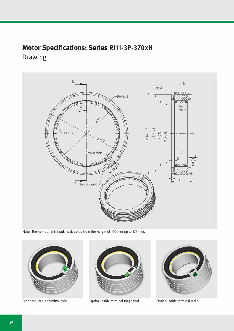
38
Motor Specifications: Series RI11-3P-370xHDrawing
Sensor cable
Motor cable
Standard: cable terminal axial Option: cable terminal tangential Option: cable terminal radial
Note: The number of threads is doubled from the height of 100 mm up to 175 mm.

39
Motor specifications Symbol Unit RI11-3P- RI11-3P- RI11-3P- RI11-3P- RI11-3P- RI11-3P- RI11-3P-
370x25 370x50 370x75 370x100 370x125 370x150 370x175
Number of pole pairs P
Maximum operating voltage UDCL VDC
Ultimate torque at Iu Tu Nm
Peak torque (saturation range) at Ip Tp Nm
Peak torque (linear range) at Ipl Tpl Nm
Continuous torque (water cooled) at Icw Tcw Nm
Continuous torque (not cooled) at Ic Tc Nm
Stall torque (water cooled) at Isw Tsw Nm
Stall torque (not cooled) at Is Ts Nm
Ripple torque (cogging) at I = 0 Tr Nm
Power loss (copper) at Tp (statical at 25 °C) Plp W
Power loss (copper) at Tpl (statical at 25 °C) Plpl W
Power loss (copper) at Tcw (statical at 100 °C) Plw W
Power loss (copper) at Tc (statical at 25 °C) Plc W
Thermical resistance (water cooled) Rth K/W
Motor constant (at 25 °C; valid up to Ipl) km Nm/√W
Water flow (cooling) dV/dt l/min
Water temperature difference (cooling) Δϑ K
Mechanical interface Symbol Unit RI11-3P- RI11-3P- RI11-3P- RI11-3P- RI11-3P- RI11-3P- RI11-3P-
370x25 370x50 370x75 370x100 370x125 370x150 370x175
Height of rotor H1
mm
Height of stator H2
mm
Mass of rotor m1
kg
Mass of stator m2
kg
Inertia of rotor J kgm2
33
600
584
424
312
216
97
153
69
1.3
3852
1504
937
145
0.107
8.03
2.68
5.00
25.0
64.0
2.8
20.9
0.087
50.0
89.0
5.6
31.4
0.174
75.0
114.0
8.4
41.3
0.261
100.0
139.0
11.2
51.1
0.348
125.0
164.0
14.0
60.9
0.435
150.0
189.0
16.7
70.8
0.522
175.0
214.0
19.5
80.6
0.609
33
600
1168
847
623
509
222
362
157
2.5
5522
2157
1874
273
0.053
13.41
5.35
5.00
33
600
1735
1258
925
812
346
576
245
3.8
7196
2811
2811
392
0.036
17.45
8.03
5.00
33
600
2313
1678
1234
1125
469
799
333
5.0
8869
3464
3748
500
0.027
20.96
10.71
5.00
33
600
2863
2076
1527
1428
573
1014
407
6.2
10542
4118
4684
581
0.021
23.79
13.38
5.00
33
600
3435
2492
1832
1744
673
1238
478
7.5
12216
4772
5621
645
0.018
26.52
16.06
5.00
33
600
4008
2907
2137
2061
774
1463
550
8.7
13889
5426
6558
712
0.015
29.02
18.74
5.00
Motor Specifications: Series RI11-3P-370xHIndependent of winding
Subject to modification without previous notice. • Tolerance range for values: ±5% • Tolerance range for value “power loss”: ±10%
IDAM will provide additional specifications and drawings per customer request. IDAM recommends that all motor applications be reviewed by an IDAM specialist.

40
18.0
14.7
77
133
162
203
309
357
273
3.35
17.2
43.2
27.7
17.3
12.0
5.4
8.5
3.8
130
100
9.6
7.9
177
272
316
408
600
682
273
0.95
4.9
81.0
51.9
32.4
22.4
10.1
15.9
7.2
130
100
4.8
3.9
385
568
646
845
1225
1377
273
0.24
1.2
162.1
103.7
64.8
44.9
20.1
31.9
14.3
130
100
36.0
29.5
29
56
76
94
140
172
-
4.81
34.4
43.2
27.7
17.3
14.1
6.2
10.0
4.4
130
100
19.2
15.7
81
122
153
197
279
332
273
1.37
9.8
81.0
51.9
32.4
26.5
11.5
18.8
8.2
130
100
9.6
7.9
186
264
316
416
578
676
273
0.34
2.4
162.1
103.7
64.8
53.0
23.1
37.6
16.4
130
100
RI11-3P-
370x25-
WL
RI11-3P-
370x25-
WM
RI11-3P-
370x25-
WH
RI11-3P-
370x50-
WL
RI11-3P-
370x50-
WM
RI11-3P-
370x50-
WH
Winding Configuration: Series RI11-3P-370xH
Winding dependent specifications
Torque constant
Back EMF constant
Limiting speed at Ip and UDCL = 280 V
Limiting speed at Icw and UDCL = 280 V
Limiting speed at Ic and UDCL = 280 V
Limiting speed at Ip and UDCL = 600 V
Limiting speed at Icw and UDCL = 600 V
Limiting speed at Ic and UDCL = 600 V
Limiting speed for continuous running*
Electrical resistance, phase to phase (25 °C)
Inductance, phase to phase
Ultimate current
Peak current (saturation range)
Peak current (linear range)
Continuous current (water cooled)
Continuous current (not cooled)
Stall current at zero speed (water cooled)
Stall current at zero speed (not cooled)
Maximum winding temperature
Interrupting sensor temperature
Symbol
kT
ku
nlp
nlw
nlc
nlp
nlw
nlc
ncr
R25
L
Iu
Ip
Ipl
Icw
Ic
Isw
Is
ϑ
ϑ
*See glossary • Subject to modification without previous notice. • Tolerance range for values: ±5% • Tolerance range for value “resistance”: ±10% • Tolerance range for value “inductance”: ±15%
Unit
Nm/Arms
Vs/rad
rpm
rpm
rpm
rpm
rpm
rpm
rpm
Ω
mH
Arms
Arms
Arms
Arms
Arms
Arms
Arms
°C
°C
Winding specific speed limits are quiet
proportional to UDCL.
A continuous running of these motors
could be limited in a range around ncr
because of additional frequency-depen-
dent losses (see glossary).
Then a further reduction of duty cycle or
current is required.
Torq
ue T
Tc
Tcw
Tp
53.5
43.8
12
31
48
58
87
112
-
6.27
51.6
43.2
27.7
17.3
15.2
6.5
10.8
4.6
130
100
RI11-3P-
370x75-
WL

41
71.4
58.4
3
19
34
39
61
82
-
7.73
68.8
43.2
27.7
17.3
15.8
6.6
11.2
4.7
130
100
38.1
31.1
32
52
73
92
129
162
-
2.20
19.6
81.0
51.9
32.4
29.6
12.3
21.0
8.7
130
100
19.0
15.6
86
121
155
202
274
333
273
0.55
4.9
162.1
103.7
64.8
59.1
24.6
42.0
17.5
130
100
88.3
72.2
-
12
26
28
45
64
-
9.19
86.0
43.2
27.7
17.3
16.2
6.5
11.5
4.6
130
100
47.1
38.5
22
39
57
71
100
128
-
2.61
24.5
81.0
51.9
32.4
30.3
12.2
21.5
8.6
130
100
23.6
19.3
66
94
124
160
216
267
-
0.65
6.1
162.1
103.7
64.8
60.6
24.3
43.0
17.3
130
100
106.0
86.7
-
7
21
20
35
52
-
10.64
103.2
43.2
27.7
17.3
16.5
6.4
11.7
4.5
130
100
56.5
46.2
15
29
47
56
80
105
-
3.03
29.3
81.0
51.9
32.4
30.8
11.9
21.9
8.5
130
100
28.3
23.1
53
75
102
131
176
220
-
0.76
7.3
162.1
103.7
64.8
61.7
23.8
43.8
16.9
130
100
123.6
101.1
-
3
17
14
28
43
-
12.10
120.4
43.2
27.7
17.3
16.7
6.3
11.8
4.4
130
100
65.9
53.9
9
23
39
46
67
89
-
3.45
34.2
81.0
51.9
32.4
31.2
11.7
22.2
8.3
130
100
33.0
27.0
43
62
87
110
148
187
-
0.86
8.6
162.1
103.7
64.8
62.5
23.5
44.4
16.7
130
100
RI11-3P-
370x100-
WL
RI11-3P-
370x100-
WM
RI11-3P-
370x100-
WH
RI11-3P-
370x125-
WL
RI11-3P-
370x125-
WM
RI11-3P-
370x125-
WH
RI11-3P-
370x150-
WL
RI11-3P-
370x150-
WM
RI11-3P-
370x150-
WH
RI11-3P-
370x175-
WL
RI11-3P-
370x175-
WM
RI11-3P-
370x175-
WH
Torq
ue T
Motor current I
Tc
Icw IplIc Ip Iu
Tcw
Tpl
Tp
Tu
28.5
23.4
49
75
100
127
179
219
-
1.78
14.7
81.0
51.9
32.4
28.4
12.1
20.2
8.6
130
100
14.3
11.7
120
169
209
274
375
449
273
0.45
3.7
162.1
103.7
64.8
56.8
24.2
40.4
17.2
130
100
RI11-3P-
370x75-
WM
RI11-3P-
370x75-
WH
Symbol
kT
ku
nlp
nlw
nlc
nlp
nlw
nlc
ncr
R25
L
Iu
Ip
Ipl
Icw
Ic
Isw
Is
ϑ
ϑ
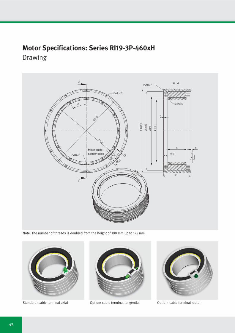
42
Motor Specifications: Series RI19-3P-460xHDrawing
Sensor cable
Motor cable
Standard: cable terminal axial Option: cable terminal tangential Option: cable terminal radial
Note: The number of threads is doubled from the height of 100 mm up to 175 mm.

43
Motor specifications Symbol Unit RI19-3P- RI19-3P- RI19-3P- RI19-3P- RI19-3P- RI19-3P- RI19-3P-
460x25 460x50 460x75 460x100 460x125 460x150 460x175
Number of pole pairs P
Maximum operating voltage UDCL VDC
Ultimate torque at Iu Tu Nm
Peak torque (saturation range) at Ip Tp Nm
Peak torque (linear range) at Ipl Tpl Nm
Continuous torque (water cooled) at Icw Tcw Nm
Continuous torque (not cooled) at Ic Tc Nm
Stall torque (water cooled) at Isw Tsw Nm
Stall torque (not cooled) at Is Ts Nm
Ripple torque (cogging) at I = 0 Tr Nm
Power loss (copper) at Tp (statical at 25 °C) Plp W
Power loss (copper) at Tpl (statical at 25 °C) Plpl W
Power loss (copper) at Tcw (statical at 100 °C) Plw W
Power loss (copper) at Tc (statical at 25 °C) Plc W
Thermical resistance (water cooled) Rth K/W
Motor constant (at 25 °C; valid up to Ipl) km Nm/√W
Water flow (cooling) dV/dt l/min
Water temperature difference (cooling) Δϑ K
Mechanical interface Symbol Unit RI19-3P- RI19-3P- RI19-3P- RI19-3P- RI19-3P- RI19-3P- RI19-3P-
460x25 460x50 460x75 460x100 460x125 460x150 460x175
Height of rotor H1
mm
Height of stator H2
mm
Mass of rotor m1
kg
Mass of stator m2
kg
Inertia of rotor J kgm2
38
600
838
642
472
323
146
229
104
1.9
4824
1884
1146
181
0.087
10.87
3.28
5.00
25.0
90.0
4.9
41.1
0.24
51.0
110.0
9.8
53.9
0.47
75.0
130.0
14.6
66.8
0.71
101.0
160.0
19.5
83.2
0.94
125.0
185.0
24.4
97.6
1.18
151.0
210.0
29.3
111.8
1.41
175.0
235.0
34.2
126.2
1.65
38
600
1675
1284
944
783
344
556
244
3.9
6560
2563
2293
339
0.044
18.65
6.55
5.00
38
600
2488
1906
1402
1252
537
889
382
5.7
8489
3316
3439
487
0.029
24.34
9.83
5.00
38
600
3317
2542
1869
1740
730
1235
518
7.6
10419
4070
4585
621
0.022
29.30
13.10
5.00
38
600
4105
3145
2313
2211
895
1570
635
9.4
12348
4824
5731
722
0.017
33.30
16.38
5.00
38
600
4926
3774
2775
2703
1052
1919
747
11.3
14278
5577
6878
802
0.015
37.16
19.65
5.00
38
600
5747
4403
3238
3197
1210
2270
859
13.2
16207
6331
8024
885
0.012
40.69
15.28
7.50
Motor Specifications: Series RI19-3P-460xHIndependent of winding
Subject to modification without previous notice. • Tolerance range for values: ±5% • Tolerance range for value “power loss”: ±10%
IDAM will provide additional specifications and drawings per customer request. IDAM recommends that all motor applications be reviewed by an IDAM specialist.

44
37.4
30.6
21
54
73
80
136
166
-
7.90
49.0
31.5
20.2
12.6
8.6
3.9
6.1
2.8
130
100
18.7
15.3
74
128
157
184
290
342
237
1.98
12.2
63.0
40.3
25.2
17.3
7.8
12.2
5.5
130
100
8.4
6.9
196
309
364
437
669
777
237
0.40
2.5
140.7
90.0
56.3
38.5
17.4
27.3
12.4
130
100
74.9
61.2
2
19
33
35
59
78
-
10.75
97.9
31.5
20.2
12.6
10.5
4.6
7.4
3.3
130
100
37.4
30.6
32
55
74
88
132
165
-
2.69
24.5
63.0
40.3
25.2
20.9
9.2
14.9
6.5
130
100
16.8
13.7
94
140
176
214
311
379
237
0.54
4.9
140.7
90.0
56.3
46.7
20.5
33.1
14.5
130
100
RI19-3P-
460x25-
WL
RI19-3P-
460x25-
WM
RI19-3P-
460x25-
WH
RI19-3P-
460x50-
WL
RI19-3P-
460x50-
WM
RI19-3P-
460x50-
WH
Winding Configuration: Series RI19-3P-460xH
Winding dependent specifications
Torque constant
Back EMF constant
Limiting speed at Ip and UDCL = 280 V
Limiting speed at Icw and UDCL = 280 V
Limiting speed at Ic and UDCL = 280 V
Limiting speed at Ip and UDCL = 600 V
Limiting speed at Icw and UDCL = 600 V
Limiting speed at Ic and UDCL = 600 V
Limiting speed for continuous running*
Electrical resistance, phase to phase (25 °C)
Inductance, phase to phase
Ultimate current
Peak current (saturation range)
Peak current (linear range)
Continuous current (water cooled)
Continuous current (not cooled)
Stall current at zero speed (water cooled)
Stall current at zero speed (not cooled)
Maximum winding temperature
Interrupting sensor temperature
Symbol
kT
ku
nlp
nlw
nlc
nlp
nlw
nlc
ncr
R25
L
Iu
Ip
Ipl
Icw
Ic
Isw
Is
ϑ
ϑ
*See glossary • Subject to modification without previous notice. • Tolerance range for values: ±5% • Tolerance range for value “resistance”: ±10% • Tolerance range for value “inductance”: ±15%
Unit
Nm/Arms
Vs/rad
rpm
rpm
rpm
rpm
rpm
rpm
rpm
Ω
mH
Arms
Arms
Arms
Arms
Arms
Arms
Arms
°C
°C
Winding specific speed limits are quiet
proportional to UDCL.
A continuous running of these motors
could be limited in a range around ncr
because of additional frequency-depen-
dent losses (see glossary).
Then a further reduction of duty cycle or
current is required.
Torq
ue T
Tc
Tcw
Tp
111.2
90.9
-
8
20
19
35
50
-
13.91
146.9
31.5
20.2
12.6
11.3
4.8
8.0
3.4
130
100
RI19-3P-
460x75-
WL

45
148.2
121.2
-
3
13
10
23
36
-
17.07
195.9
31.5
20.2
12.6
11.7
4.9
8.3
3.5
130
100
74.1
60.6
9
21
34
39
58
79
-
4.27
49.0
63.0
40.3
25.2
23.5
9.9
16.7
7.0
130
100
33.2
27.2
42
62
85
103
144
185
-
0.86
9.8
140.7
90.0
56.3
52.4
22.0
37.2
15.6
130
100
183.4
150.0
-
-
10
5
16
27
-
20.23
244.8
31.5
20.2
12.6
12.1
4.9
8.6
3.5
130
100
91.7
75.0
3
14
27
29
44
62
-
5.06
61.2
63.0
40.3
25.2
24.1
9.8
17.1
6.9
130
100
41.1
33.6
31
48
68
81
113
148
-
1.02
12.3
140.7
90.0
56.3
53.8
21.8
38.2
15.5
130
100
220.1
180.0
-
-
7
1
11
22
-
23.39
293.8
31.5
20.2
12.6
12.3
4.8
8.7
3.4
130
100
110.1
90.0
-
10
21
22
35
50
-
5.85
73.5
63.0
40.3
25.2
24.6
9.6
17.4
6.8
130
100
49.3
40.3
24
38
56
66
92
122
-
1.18
14.8
140.7
90.0
56.3
54.8
21.3
38.9
15.1
130
100
256.8
210.0
-
-
6
-
7
17
-
26.55
342.8
31.5
20.2
12.6
12.4
4.7
8.8
3.3
130
100
128.4
105.0
-
6
18
17
28
42
-
6.64
85.7
63.0
40.3
25.2
24.9
9.4
17.7
6.7
130
100
57.5
47.1
19
31
47
55
77
103
-
1.33
17.2
140.7
90.0
56.3
55.5
21.0
39.4
14.9
130
100
RI19-3P-
460x100-
WL
RI19-3P-
460x100-
WM
RI19-3P-
460x100-
WH
RI19-3P-
460x125-
WL
RI19-3P-
460x125-
WM
RI19-3P-
460x125-
WH
RI19-3P-
460x150-
WL
RI19-3P-
460x150-
WM
RI19-3P-
460x150-
WH
RI19-3P-
460x175-
WL
RI19-3P-
460x175-
WM
RI19-3P-
460x175-
WH
Torq
ue T
Motor current I
Tc
Icw IplIc Ip Iu
Tcw
Tpl
Tp
Tu
55.6
45.5
17
32
48
55
82
108
-
3.48
36.7
63.0
40.3
25.2
22.5
9.7
16.0
6.9
130
100
24.9
20.4
59
88
116
140
199
250
237
0.70
7.4
140.7
90.0
56.3
50.2
21.6
35.7
15.3
130
100
RI19-3P-
460x75-
WM
RI19-3P-
460x75-
WH
Symbol
kT
ku
nlp
nlw
nlc
nlp
nlw
nlc
ncr
R25
L
Iu
Ip
Ipl
Icw
Ic
Isw
Is
ϑ
ϑ
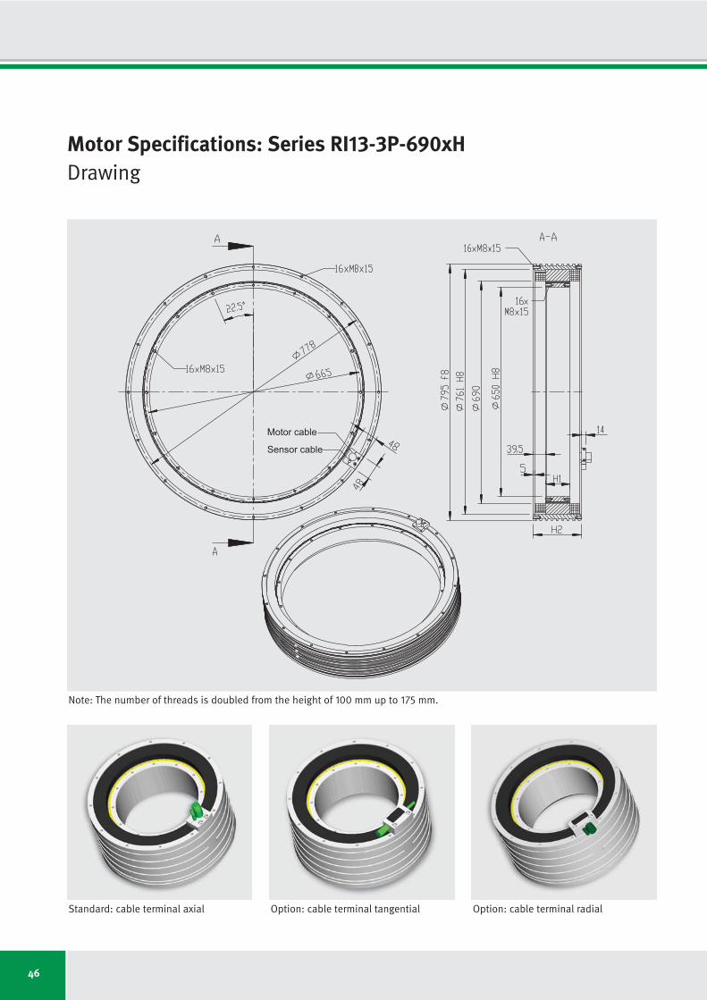
46
Motor Specifications: Series RI13-3P-690xHDrawing
Sensor cable
Motor cable
Standard: cable terminal axial Option: cable terminal tangential Option: cable terminal radial
Note: The number of threads is doubled from the height of 100 mm up to 175 mm.

47
Motor specifications Symbol Unit RI13-3P- RI13-3P- RI13-3P- RI13-3P- RI13-3P- RI13-3P- RI13-3P-
690x25 690x50 690x75 690x100 690x125 690x150 690x175
Number of pole pairs P
Maximum operating voltage UDCL VDC
Ultimate torque at Iu Tu Nm
Peak torque (saturation range) at Ip Tp Nm
Peak torque (linear range) at Ipl Tpl Nm
Continuous torque (water cooled) at Icw Tcw Nm
Continuous torque (not cooled) at Ic Tc Nm
Stall torque (water cooled) at Isw Tsw Nm
Stall torque (not cooled) at Is Ts Nm
Ripple torque (cogging) at I = 0 Tr Nm
Power loss (copper) at Tp (statical at 25 °C) Plp W
Power loss (copper) at Tpl (statical at 25 °C) Plpl W
Power loss (copper) at Tcw (statical at 100 °C) Plw W
Power loss (copper) at Tc (statical at 25 °C) Plc W
Thermical resistance (water cooled) Rth K/W
Motor constant (at 25 °C; valid up to Ipl) km Nm/√W
Water flow (cooling) dV/dt l/min
Water temperature difference (cooling) Δϑ K
Mechanical interface Symbol Unit RI13-3P- RI13-3P- RI13-3P- RI13-3P- RI13-3P- RI13-3P- RI13-3P-
690x25 690x50 690x75 690x100 690x125 690x150 690x175
Height of rotor H1
mm
Height of stator H2
mm
Mass of rotor m1
kg
Mass of stator m2
kg
Inertia of rotor J kgm2
65
600
1947
1471
1082
708
328
503
233
4.4
7544
2947
1643
271
0.061
19.92
4.69
5.00
25.0
110.0
7.6
69.7
0.85
51.0
130.0
15.2
88.1
1.70
75.0
150.0
22.8
106.4
2.55
101.0
180.0
30.4
129.0
3.40
125.0
205.0
38.0
149.3
4.25
151.0
230.0
45.6
169.8
5.10
175.0
255.0
53.2
190.2
5.95
65
600
3894
2942
2163
1683
755
1195
536
8.8
10687
4175
3286
509
0.030
33.48
9.39
5.00
65
600
5782
4369
3212
2691
1182
1911
839
13.1
13830
5402
4928
731
0.020
43.70
14.08
5.00
65
600
7709
5825
4283
3740
1606
2655
1140
17.5
16973
6630
6571
932
0.015
52.60
18.77
5.00
65
600
9539
7208
5300
4752
1968
3374
1397
21.6
20116
7858
8214
1083
0.012
59.79
15.65
7.50
65
600
11447
8649
6360
5810
2314
4125
1643
25.9
23259
9086
9857
1202
0.010
66.72
18.77
7.50
65
600
13355
10091
7420
6871
2661
4879
1890
30.3
26403
10314
11500
1327
0.009
73.06
16.43
10.00
Motor Specifications: Series RI13-3P-690xHIndependent of winding
Subject to modification without previous notice. • Tolerance range for values: ±5% • Tolerance range for value “power loss”: ±10%
IDAM will provide additional specifications and drawings per customer request. IDAM recommends that all motor applications be reviewed by an IDAM specialist.

48
35.9
29.4
33
64
80
89
149
177
138
2.17
12.0
75.3
48.2
30.1
19.7
9.1
14.0
6.5
130
100
25.0
20.4
56
98
118
135
220
257
138
1.05
5.8
108.4
69.3
43.3
28.3
13.1
20.1
9.3
130
100
20.0
16.3
74
126
150
172
278
324
138
0.67
3.7
135.4
86.7
54.2
35.4
16.4
25.1
11.6
130
100
71.8
58.7
12
26
37
41
67
85
-
3.07
24.0
75.3
48.2
30.1
23.4
10.5
16.6
7.5
130
100
49.9
40.8
24
43
56
64
101
124
-
1.49
11.6
108.4
69.3
43.3
33.7
15.1
23.9
10.7
130
100
39.9
32.7
33
56
72
83
128
157
138
0.95
7.4
135.4
86.7
54.2
42.1
18.9
29.9
13.4
130
100
RI13-3P-
690x25-
WL
RI13-3P-
690x25-
WM
RI13-3P-
690x25-
WH
RI13-3P-
690x50-
WL
RI13-3P-
690x50-
WM
RI13-3P-
690x50-
WH
Winding Configuration: Series RI13-3P-690xH
Winding dependent specifications
Torque constant
Back EMF constant
Limiting speed at Ip and UDCL = 280 V
Limiting speed at Icw and UDCL = 280 V
Limiting speed at Ic and UDCL = 280 V
Limiting speed at Ip and UDCL = 600 V
Limiting speed at Icw and UDCL = 600 V
Limiting speed at Ic and UDCL = 600 V
Limiting speed for continuous running*
Electrical resistance, phase to phase (25 °C)
Inductance, phase to phase
Ultimate current
Peak current (saturation range)
Peak current (linear range)
Continuous current (water cooled)
Continuous current (not cooled)
Stall current at zero speed (water cooled)
Stall current at zero speed (not cooled)
Maximum winding temperature
Interrupting sensor temperature
Symbol
kT
ku
nlp
nlw
nlc
nlp
nlw
nlc
ncr
R25
L
Iu
Ip
Ipl
Icw
Ic
Isw
Is
ϑ
ϑ
*See glossary • Subject to modification without previous notice. • Tolerance range for values: ±5% • Tolerance range for value “resistance”: ±10% • Tolerance range for value “inductance”: ±15%
Unit
Nm/Arms
Vs/rad
rpm
rpm
rpm
rpm
rpm
rpm
rpm
Ω
mH
Arms
Arms
Arms
Arms
Arms
Arms
Arms
°C
°C
Winding specific speed limits are quiet
proportional to UDCL.
A continuous running of these motors
could be limited in a range around ncr
because of additional frequency-depen-
dent losses (see glossary).
Then a further reduction of duty cycle or
current is required.
Torq
ue T
Tc
Tcw
Tp
106.6
87.2
4
15
24
25
41
55
-
3.97
36.0
75.3
48.2
30.1
25.2
11.1
17.9
7.9
130
100
RI13-3P-
690x75-
WL

49
142.2
116.3
-
9
17
17
29
40
-
4.87
48.1
75.3
48.2
30.1
26.3
11.3
18.7
8.0
130
100
98.8
80.8
7
17
26
29
45
60
-
2.36
23.2
108.4
69.3
43.3
37.8
16.2
26.8
11.5
130
100
79.1
64.7
13
23
34
39
58
76
-
1.51
14.9
135.4
86.7
54.2
47.2
20.3
33.5
14.4
130
100
175.9
143.9
-
5
13
12
21
31
-
5.77
60.1
75.3
48.2
30.1
27.0
11.2
19.2
7.9
130
100
122.3
100.0
3
12
20
22
34
47
-
2.80
29.0
108.4
69.3
43.3
38.8
16.1
27.5
11.4
130
100
97.8
80.0
8
17
27
30
45
60
-
1.79
18.6
135.4
86.7
54.2
48.5
20.1
34.4
14.2
130
100
211.1
172.7
-
3
10
8
17
25
-
6.68
72.1
75.3
48.2
30.1
27.5
11.0
19.5
7.8
130
100
146.7
120.0
-
8
17
17
27
38
-
3.24
34.8
108.4
69.3
43.3
39.5
15.7
28.1
11.2
130
100
117.4
96.0
5
13
22
23
36
49
-
2.07
22.3
135.4
86.7
54.2
49.4
19.7
35.1
14.0
130
100
246.3
201.5
-
1
8
5
13
21
-
7.58
84.1
75.3
48.2
30.1
27.9
10.8
19.8
7.7
130
100
171.2
140.0
-
6
14
13
22
32
-
3.67
40.6
108.4
69.3
43.3
40.1
15.5
28.4
11.0
130
100
137.0
112.0
2
10
18
19
30
41
-
2.35
26.0
135.4
86.7
54.2
50.1
19.4
35.5
13.8
130
100
RI13-3P-
690x100-
WL
RI13-3P-
690x100-
WM
RI13-3P-
690x100-
WH
RI13-3P-
690x125-
WL
RI13-3P-
690x125-
WM
RI13-3P-
690x125-
WH
RI13-3P-
690x150-
WL
RI13-3P-
690x150-
WM
RI13-3P-
690x150-
WH
RI13-3P-
690x175-
WL
RI13-3P-
690x175-
WM
RI13-3P-
690x175-
WH
Torq
ue T
Motor current I
Tc
Icw IplIc Ip Iu
Tcw
Tpl
Tp
Tu
74.1
60.6
13
25
36
41
63
81
-
1.92
17.4
108.4
69.3
43.3
36.2
15.9
25.7
11.3
130
100
59.3
48.5
20
34
47
54
81
103
-
1.23
11.1
135.4
86.7
54.2
45.3
19.9
32.1
14.1
130
100
RI13-3P-
690x75-
WM
RI13-3P-
690x75-
WH
Symbol
kT
ku
nlp
nlw
nlc
nlp
nlw
nlc
ncr
R25
L
Iu
Ip
Ipl
Icw
Ic
Isw
Is
ϑ
ϑ
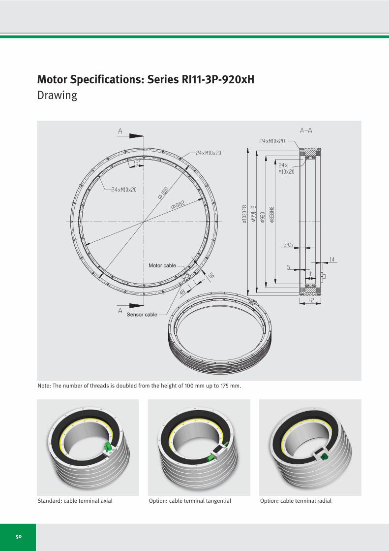
50
Motor Specifications: Series RI11-3P-920xHDrawing
Sensor cable
Motor cable
Standard: cable terminal axial Option: cable terminal tangential Option: cable terminal radial
Note: The number of threads is doubled from the height of 100 mm up to 175 mm.

51
Motor specifications Symbol Unit RI11-3P- RI11-3P- RI11-3P- RI11-3P- RI11-3P- RI11-3P- RI11-3P-
920x25 920x50 920x75 920x100 920x125 920x150 920x175
Number of pole pairs P
Maximum operating voltage UDCL VDC
Ultimate torque at Iu Tu Nm
Peak torque (saturation range) at Ip Tp Nm
Peak torque (linear range) at Ipl Tpl Nm
Continuous torque (water cooled) at Icw Tcw Nm
Continuous torque (not cooled) at Ic Tc Nm
Stall torque (water cooled) at Isw Tsw Nm
Stall torque (not cooled) at Is Ts Nm
Ripple torque (cogging) at I = 0 Tr Nm
Power loss (copper) at Tp (statical at 25 °C) Plp W
Power loss (copper) at Tpl (statical at 25 °C) Plpl W
Power loss (copper) at Tcw (statical at 100 °C) Plw W
Power loss (copper) at Tc (statical at 25 °C) Plc W
Thermical resistance (water cooled) Rth K/W
Motor constant (at 25 °C; valid up to Ipl) km Nm/√W
Water flow (cooling) dV/dt l/min
Water temperature difference (cooling) Δϑ K
Mechanical interface Symbol Unit RI11-3P- RI11-3P- RI11-3P- RI11-3P- RI11-3P- RI11-3P- RI11-3P-
920x25 920x50 920x75 920x100 920x125 920x150 920x175
Height of rotor H1
mm
Height of stator H2
mm
Mass of rotor m1
kg
Mass of stator m2
kg
Inertia of rotor J kgm2
66
600
3681
3323
1888
1249
585
887
415
10.0
15046
3761
2139
361
0.047
30.78
6.11
5.00
25.0
110.0
15.6
100.9
3.07
51.0
130.0
31.1
127.2
6.14
75.0
150.0
46.7
152.6
9.21
101.0
180.0
62.3
184.0
12.28
125.0
205.0
77.8
212.5
15.35
151.0
230.0
93.4
241.0
18.42
175.0
255.0
109.0
269.4
21.49
66
600
7363
6645
3776
2967
1348
2107
957
19.9
21315
5329
4279
679
0.023
51.72
12.22
5.00
66
600
11044
9968
5664
4792
2130
3402
1512
29.9
27584
6896
6418
975
0.016
68.20
18.34
5.00
66
600
14725
13290
7551
6660
2893
4728
2054
39.9
33853
8463
8557
1242
0.012
82.08
16.30
7.50
66
600
18406
16613
9439
8549
3582
6070
2543
49.8
40122
10031
10697
1444
0.009
94.25
15.28
10.00
66
600
22088
19936
11327
10451
4211
7420
2990
59.8
46392
11598
12836
1603
0.008
105.18
18.34
10.00
76
600
25769
23258
13215
12361
4845
8777
3440
69.8
52661
13165
14975
1769
0.007
115.17
17.11
12.50
Motor Specifications: Series RI11-3P-920xHIndependent of winding
Subject to modification without previous notice. • Tolerance range for values: ±5% • Tolerance range for value “power loss”: ±10%
IDAM will provide additional specifications and drawings per customer request. IDAM recommends that all motor applications be reviewed by an IDAM specialist.

52
59.2
48.4
13
39
48
51
95
108
-
2.5
13.5
79.8
63.8
31.9
21.0
9.8
14.9
7.0
130
100
36.0
29.5
36
72
83
95
162
181
136
0.9
5.0
130.9
104.7
52.4
34.6
16.2
24.6
11.5
130
100
21.4
17.5
73
127
143
170
280
308
136
0.3
1.8
220.1
176.1
88.0
58.1
27.2
41.3
19.3
130
100
118.3
96.8
-
16
22
22
42
52
-
3.5
27.0
79.8
63.8
31.9
24.9
11.3
17.7
8.0
130
100
72.1
59.0
14
31
39
44
75
88
136
1.3
10.0
130.9
104.7
52.4
41.2
18.7
29.2
13.3
130
100
42.9
35.1
33
58
69
82
132
151
136
0.5
3.6
220.1
176.1
88.0
69.1
31.4
49.0
22.3
130
100
RI11-3P-
920x25-
WLZ
RI11-3P-
920x25-
WMZ
RI11-3P-
920x25-
WHZ
RI11-3P-
920x50-
WLZ
RI11-3P-
920x50-
WMZ
RI11-3P-
920x50-
WHZ
Winding Configuration: Series RI11-3P-920xH
Winding dependent specifications
Torque constant
Back EMF constant
Limiting speed at Ip and UDCL = 280 V
Limiting speed at Icw and UDCL = 280 V
Limiting speed at Ic and UDCL = 280 V
Limiting speed at Ip and UDCL = 600 V
Limiting speed at Icw and UDCL = 600 V
Limiting speed at Ic and UDCL = 600 V
Limiting speed for continuous running*
Electrical resistance, phase to phase (25 °C)
Inductance, phase to phase
Ultimate current
Peak current (saturation range)
Peak current (linear range)
Continuous current (water cooled)
Continuous current (not cooled)
Stall current at zero speed (water cooled)
Stall current at zero speed (not cooled)
Maximum winding temperature
Interrupting sensor temperature
Symbol
kT
ku
nlp
nlw
nlc
nlp
nlw
nlc
ncr
R25
L
Iu
Ip
Ipl
Icw
Ic
Isw
Is
ϑ
ϑ
*See glossary • Subject to modification without previous notice. • Tolerance range for values: ±5% • Tolerance range for value “resistance”: ±10% • Tolerance range for value “inductance”: ±15%
Unit
Nm/Arms
Vs/rad
rpm
rpm
rpm
rpm
rpm
rpm
rpm
Ω
mH
Arms
Arms
Arms
Arms
Arms
Arms
Arms
°C
°C
Winding specific speed limits are quiet
proportional to UDCL.
A continuous running of these motors
could be limited in a range around ncr
because of additional frequency-depen-
dent losses (see glossary).
Then a further reduction of duty cycle or
current is required.
Torq
ue T
Tc
Tcw
Tp
177.5
145.2
-
8
14
12
26
33
-
4.6
40.6
79.8
63.8
31.9
26.8
11.9
19.1
8.5
130
100
RI11-3P-
920x75-
WLZ

53
236.6
193.5
-
4
9
6
17
24
-
5.6
54.1
79.8
63.8
31.9
28.0
12.2
19.9
8.6
130
100
144.2
117.9
1
12
18
18
33
42
136
2.1
20.1
130.9
104.7
52.4
46.2
20.1
32.8
14.2
130
100
85.8
70.2
12
25
33
38
61
74
136
0.7
7.1
220.1
176.1
88.0
77.5
33.7
55.0
23.9
130
100
295.8
241.9
-
2
7
3
13
19
-
6.6
67.6
79.8
63.8
31.9
28.7
12.0
20.4
8.5
130
100
180.2
147.4
-
8
14
13
25
33
136
2.4
25.1
130.9
104.7
52.4
47.4
19.9
33.7
14.1
130
100
107.2
87.7
8
19
26
29
47
58
136
0.9
8.9
220.1
176.1
88.0
79.6
33.3
56.5
23.7
130
100
354.9
290.3
-
-
5
-
9
15
-
7.7
81.1
79.8
63.8
31.9
29.3
11.8
20.8
8.4
130
100
216.3
176.9
-
6
11
9
20
27
136
2.8
30.1
130.9
104.7
52.4
48.3
19.5
34.3
13.8
130
100
128.7
105.2
5
15
21
23
38
48
136
1.0
10.7
220.1
176.1
88.0
81.1
32.7
57.6
23.2
130
100
414.1
338.7
-
-
4
-
7
13
-
8.7
94.7
79.8
63.8
31.9
29.7
11.6
21.1
8.3
130
100
252.3
206.4
-
4
9
7
16
23
136
3.2
35.1
130.9
104.7
52.4
49.0
19.2
34.8
13.6
130
100
150.1
122.8
2
11
18
18
32
41
136
1.1
12.4
220.1
176.1
88.0
82.2
32.2
58.4
22.9
130
100
RI11-3P-
920x100-
WLZ
RI11-3P-
920x100-
WMZ
RI11-3P-
920x100-
WHZ
RI11-3P-
920x125-
WLZ
RI11-3P-
920x125-
WMZ
RI11-3P-
920x125-
WHZ
RI11-3P-
920x150-
WLZ
RI11-3P-
920x150-
WMZ
RI11-3P-
920x150-
WHZ
RI11-3P-
920x175-
WLZ
RI11-3P-
920x175-
WMZ
RI11-3P-
920x175-
WHZ
Torq
ue T
Motor current I
Tc
Icw IplIc Ip Iu
Tcw
Tpl
Tp
Tu
108.1
88.5
6
18
25
27
47
57
136
1.7
15.1
130.9
104.7
52.4
44.3
19.7
31.5
14.0
130
100
64.3
52.6
19
36
45
52
84
99
136
0.6
5.3
220.1
176.1
88.0
74.4
33.0
52.8
23.5
130
100
RI11-3P-
920x75-
WMZ
RI11-3P-
920x75-
WHZ
Symbol
kT
ku
nlp
nlw
nlc
nlp
nlw
nlc
ncr
R25
L
Iu
Ip
Ipl
Icw
Ic
Isw
Is
ϑ
ϑ
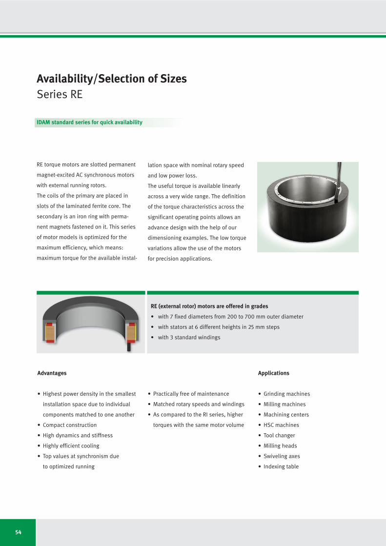
54
RE (external rotor) motors are offered in grades
• with 7 fixed diameters from 200 to 700 mm outer diameter
• with stators at 6 different heights in 25 mm steps
• with 3 standard windings
Advantages
• Highest power density in the smallest
installation space due to individual
components matched to one another
• Compact construction
• High dynamics and stiffness
• Highly efficient cooling
• Top values at synchronism due
to optimized running
• Practically free of maintenance
• Matched rotary speeds and windings
• As compared to the RI series, higher
torques with the same motor volume
Applications
• Grinding machines
• Milling machines
• Machining centers
• HSC machines
• Tool changer
• Milling heads
• Swiveling axes
• Indexing table
Availability/Selection of Sizes Series RE
RE torque motors are slotted permanent
magnet-excited AC synchronous motors
with external running rotors.
The coils of the primary are placed in
slots of the laminated ferrite core. The
secondary is an iron ring with perma-
nent magnets fastened on it. This series
of motor models is optimized for the
maximum efficiency, which means:
maximum torque for the available instal-
lation space with nominal rotary speed
and low power loss.
The useful torque is available linearly
across a very wide range. The definition
of the torque characteristics across the
significant operating points allows an
advance design with the help of our
dimensioning examples. The low torque
variations allow the use of the motors
for precision applications.
IDAM standard series for quick availability

55
DesignationSeries RE
XXXX - 3P - DxH - X-X-X-X - XXX
PRIM Primary
SEK Secondary
Model variant
O Built-in set (motor is integrated in customer’s system)
M Complete motor (parts are manufactured by IDAM)
K With cooling in the ring (additional ring is provided
by IDAM)
Commutation type
O Without sensors, measurement system commutated
XX Other designs after discussion
Winding designs
WL Low speed, low current requirement
WM Medium speed
WH High speed, large current requirement
XX Other winding designs, e.g. LDX ... HDX
Dimensions
Effective diameter in the air gap x package height (mm)
Number of motor phases
3P 3-phase
Construction characteristics
Motor type
RE Rotary external (external running)
For unique identification of the motor, the 6-digit IDAM item-number of the order confirmation is binding.
Temperature monitoring
O Standard (KTY84-130 and 3x PTC in series at the
phases 1, 2, 3 | 1x KTY84 phase 2 as reserve)
S Special design after discussions with
manufacturer
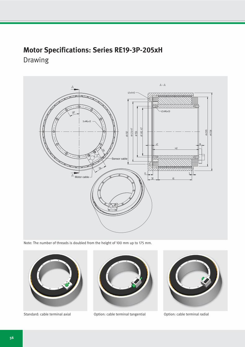
56
Motor Specifications: Series RE19-3P-205xHDrawing
Sensor cable
Motor cable
Standard: cable terminal axial Option: cable terminal tangential Option: cable terminal radial
Note: The number of threads is doubled from the height of 100 mm up to 175 mm.

57
Motor specifications Symbol Unit RE19-3P- RE19-3P- RE19-3P- RE19-3P- RE19-3P- RE19-3P- RE19-3P-
205x25 205x50 205x75 205x100 205x125 205x150 205x175
Number of pole pairs P
Maximum operating voltage UDCL VDC
Ultimate torque at Iu Tu Nm
Peak torque (saturation range) at Ip Tp Nm
Peak torque (linear range) at Ipl Tpl Nm
Continuous torque (water cooled) at Icw Tcw Nm
Continuous torque (not cooled) at Ic Tc Nm
Stall torque (water cooled) at Isw Tsw Nm
Stall torque (not cooled) at Is Ts Nm
Ripple torque (cogging) at I = 0 Tr Nm
Power loss (copper) at Tp (statical at 25 °C) Plp W
Power loss (copper) at Tpl (statical at 25 °C) Plpl W
Power loss (copper) at Tcw (statical at 100 °C) Plw W
Power loss (copper) at Tc (statical at 25 °C) Plc W
Thermical resistance (water cooled) Rth K/W
Motor constant (at 25 °C; valid up to Ipl) km Nm/√W
Water flow (cooling) dV/dt l/min
Water temperature difference (cooling) Δϑ K
Mechanical interface Symbol Unit RE19-3P- RE19-3P- RE19-3P- RE19-3P- RE19-3P- RE19-3P- RE19-3P-
205x25 205x50 205x75 205x100 205x125 205x150 205x175
Height of rotor H1
mm
Height of stator H2
mm
Mass of rotor m1
kg
Mass of stator m2
kg
Inertia of rotor J kgm2
19
600
134
114
79
39
21
27
15
0.3
2848
1113
348
80
0.288
2.36
0.99
5.00
25.0
60.0
4.0
6.2
0.0461
50.0
85.0
5.5
9.3
0.0636
75.0
110.0
6.9
12.5
0.0811
100.0
135.0
8.4
15.6
0.0986
125.0
160.0
9.8
18.6
0.1161
150.0
185.0
11.3
21.7
0.1336
175.0
210.0
12.7
24.8
0.1511
19
600
252
215
158
90
48
64
34
0.6
4205
1643
695
151
0.144
3.89
1.99
5.00
19
600
379
322
237
144
75
102
53
1.0
5561
2172
1043
217
0.096
5.08
2.98
5.00
19
600
505
429
315
198
101
141
72
1.3
6918
2702
1390
277
0.072
6.07
3.97
5.00
19
600
631
536
394
254
124
180
88
1.6
8274
3232
1738
322
0.058
6.94
4.97
5.00
19
600
757
644
473
309
146
219
104
1.9
9630
3762
2085
357
0.048
7.72
5.96
5.00
19
600
883
751
552
365
167
259
119
2.3
10987
4292
2433
394
0.041
8.43
6.95
5.00
Motor Specifications: Series RE19-3P-205xHIndependent of winding
Subject to modification without previous notice. • Tolerance range for values: ±5% • Tolerance range for value “power loss”: ±10%
IDAM will provide additional specifications and drawings per customer request. IDAM recommends that all motor applications be reviewed by an IDAM specialist.

58
7.66
6.27
160
340
383
465
781
845
474
7.00
20.7
20.6
16.5
10.3
5.0
2.8
3.6
2.0
130
100
3.83
3.13
437
739
801
1029
1620
1725
474
1.75
5.2
41.2
32.9
20.6
10.1
5.5
7.2
3.9
130
100
2.07
1.69
892
1416
1511
1980
3048
3223
474
0.51
1.5
76.2
61.0
38.1
18.6
10.2
13.2
7.3
130
100
15.32
12.53
46
146
179
207
362
407
-
10.33
41.3
20.6
16.5
10.3
5.9
3.1
4.2
2.2
130
100
7.66
6.27
192
342
387
492
773
844
474
2.58
10.3
41.2
32.9
20.6
11.7
6.2
8.3
4.4
130
100
4.14
3.39
423
673
740
969
1471
1587
474
0.76
3.0
76.2
61.0
38.1
21.7
11.5
15.4
8.2
130
100
RE19-3P-
205x25-
WL
RE19-3P-
205x25-
WM
RE19-3P-
205x25-
WH
RE19-3P-
205x50-
WL
RE19-3P-
205x50-
WM
RE19-3P-
205x50-
WH
Winding Configuration: Series RE19-3P-205xH
Winding dependent specifications
Torque constant
Back EMF constant
Limiting speed at Ip and UDCL = 280 V
Limiting speed at Icw and UDCL = 280 V
Limiting speed at Ic and UDCL = 280 V
Limiting speed at Ip and UDCL = 600 V
Limiting speed at Icw and UDCL = 600 V
Limiting speed at Ic and UDCL = 600 V
Limiting speed for continuous running*
Electrical resistance, phase to phase (25 °C)
Inductance, phase to phase
Ultimate current
Peak current (saturation range)
Peak current (linear range)
Continuous current (water cooled)
Continuous current (not cooled)
Stall current at zero speed (water cooled)
Stall current at zero speed (not cooled)
Maximum winding temperature
Interrupting sensor temperature
Symbol
kT
ku
nlp
nlw
nlc
nlp
nlw
nlc
ncr
R25
L
Iu
Ip
Ipl
Icw
Ic
Isw
Is
ϑ
ϑ
*See glossary • Subject to modification without previous notice. • Tolerance range for values: ±5% • Tolerance range for value “resistance”: ±10% • Tolerance range for value “inductance”: ±15%
Unit
Nm/Arms
Vs/rad
rpm
rpm
rpm
rpm
rpm
rpm
rpm
Ω
mH
Arms
Arms
Arms
Arms
Arms
Arms
Arms
°C
°C
Winding specific speed limits are quiet
proportional to UDCL.
A continuous running of these motors
could be limited in a range around ncr
because of additional frequency-depen-
dent losses (see glossary).
Then a further reduction of duty cycle or
current is required.
Torq
ue T
Tc
Tcw
Tp
22.98
18.80
2
83
112
119
226
263
-
13.66
62.0
20.6
16.5
10.3
6.3
3.3
4.4
2.3
130
100
RE19-3P-
205x75-
WL
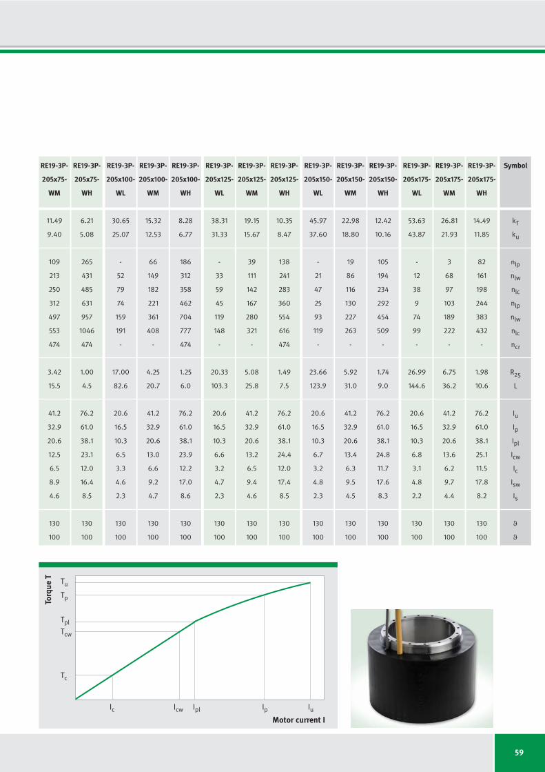
59
30.65
25.07
-
52
79
74
159
191
-
17.00
82.6
20.6
16.5
10.3
6.5
3.3
4.6
2.3
130
100
15.32
12.53
66
149
182
221
361
408
-
4.25
20.7
41.2
32.9
20.6
13.0
6.6
9.2
4.7
130
100
8.28
6.77
186
312
358
462
704
777
474
1.25
6.0
76.2
61.0
38.1
23.9
12.2
17.0
8.6
130
100
38.31
31.33
-
33
59
45
119
148
-
20.33
103.3
20.6
16.5
10.3
6.6
3.2
4.7
2.3
130
100
19.15
15.67
39
111
142
167
280
321
-
5.08
25.8
41.2
32.9
20.6
13.2
6.5
9.4
4.6
130
100
10.35
8.47
138
241
283
360
554
616
474
1.49
7.5
76.2
61.0
38.1
24.4
12.0
17.4
8.5
130
100
45.97
37.60
-
21
47
25
93
119
-
23.66
123.9
20.6
16.5
10.3
6.7
3.2
4.8
2.3
130
100
22.98
18.80
19
86
116
130
227
263
-
5.92
31.0
41.2
32.9
20.6
13.4
6.3
9.5
4.5
130
100
12.42
10.16
105
194
234
292
454
509
-
1.74
9.0
76.2
61.0
38.1
24.8
11.7
17.6
8.3
130
100
53.63
43.87
-
12
38
9
74
99
-
26.99
144.6
20.6
16.5
10.3
6.8
3.1
4.8
2.2
130
100
26.81
21.93
3
68
97
103
189
222
-
6.75
36.2
41.2
32.9
20.6
13.6
6.2
9.7
4.4
130
100
14.49
11.85
82
161
198
244
383
432
-
1.98
10.6
76.2
61.0
38.1
25.1
11.5
17.8
8.2
130
100
RE19-3P-
205x100-
WL
RE19-3P-
205x100-
WM
RE19-3P-
205x100-
WH
RE19-3P-
205x125-
WL
RE19-3P-
205x125-
WM
RE19-3P-
205x125-
WH
RE19-3P-
205x150-
WL
RE19-3P-
205x150-
WM
RE19-3P-
205x150-
WH
RE19-3P-
205x175-
WL
RE19-3P-
205x175-
WM
RE19-3P-
205x175-
WH
Torq
ue T
Motor current I
Tc
Icw IplIc Ip Iu
Tcw
Tpl
Tp
Tu
11.49
9.40
109
213
250
312
497
553
474
3.42
15.5
41.2
32.9
20.6
12.5
6.5
8.9
4.6
130
100
6.21
5.08
265
431
485
631
957
1046
474
1.00
4.5
76.2
61.0
38.1
23.1
12.0
16.4
8.5
130
100
RE19-3P-
205x75-
WM
RE19-3P-
205x75-
WH
Symbol
kT
ku
nlp
nlw
nlc
nlp
nlw
nlc
ncr
R25
L
Iu
Ip
Ipl
Icw
Ic
Isw
Is
ϑ
ϑ
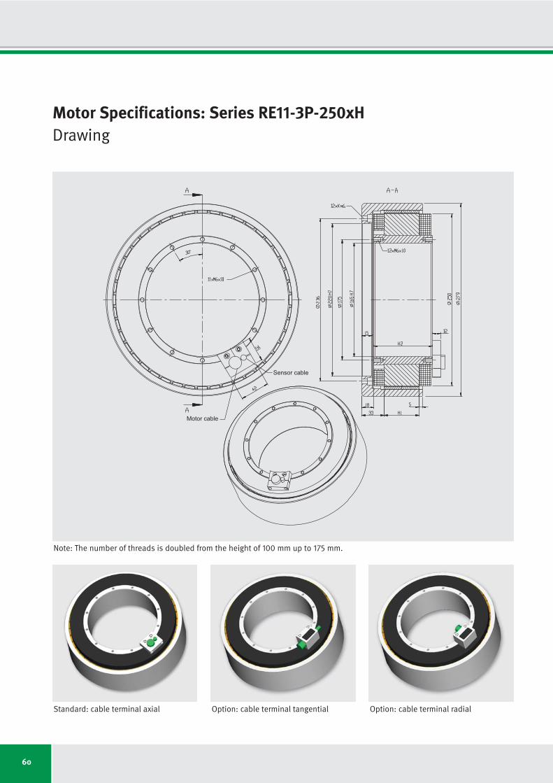
60
Motor Specifications: Series RE11-3P-250xHDrawing
Sensor cable
Motor cable
Standard: cable terminal axial Option: cable terminal tangential Option: cable terminal radial
Note: The number of threads is doubled from the height of 100 mm up to 175 mm.

61
Motor specifications Symbol Unit RE11-3P- RE11-3P- RE11-3P- RE11-3P- RE11-3P- RE11-3P- RE11-3P-
250x25 250x50 250x75 250x100 250x125 250x150 250x175
Number of pole pairs P
Maximum operating voltage UDCL VDC
Ultimate torque at Iu Tu Nm
Peak torque (saturation range) at Ip Tp Nm
Peak torque (linear range) at Ipl Tpl Nm
Continuous torque (water cooled) at Icw Tcw Nm
Continuous torque (not cooled) at Ic Tc Nm
Stall torque (water cooled) at Isw Tsw Nm
Stall torque (not cooled) at Is Ts Nm
Ripple torque (cogging) at I = 0 Tr Nm
Power loss (copper) at Tp (statical at 25 °C) Plp W
Power loss (copper) at Tpl (statical at 25 °C) Plpl W
Power loss (copper) at Tcw (statical at 100 °C) Plw W
Power loss (copper) at Tc (statical at 25 °C) Plc W
Thermical resistance (water cooled) Rth K/W
Motor constant (at 25 °C; valid up to Ipl) km Nm/√W
Water flow (cooling) dV/dt l/min
Water temperature difference (cooling) Δϑ K
Mechanical interface Symbol Unit RE11-3P- RE11-3P- RE11-3P- RE11-3P- RE11-3P- RE11-3P- RE11-3P-
250x25 250x50 250x75 250x100 250x125 250x150 250x175
Height of rotor H1
mm
Height of stator H2
mm
Mass of rotor m1
kg
Mass of stator m2
kg
Inertia of rotor J kgm2
22
600
249
178
131
69
39
49
27
0.5
2867
1120
402
98
0.249
3.91
1.15
5.00
25.0
60.0
6.2
9.4
0.1056
50.0
85.0
8.3
14.2
0.1424
75.0
110.0
10.4
19.0
0.1792
100.0
135.0
12.4
23.8
0.2160
125.0
160.0
14.5
28.6
0.2528
150.0
185.0
16.6
33.5
0.2896
175.0
210.0
18.7
38.3
0.3264
22
600
497
356
262
162
89
115
63
1.1
4114
1607
803
184
0.125
6.53
2.29
5.00
22
600
738
528
389
258
138
184
98
1.6
5361
2094
1205
265
0.083
8.49
3.44
5.00
22
600
984
705
518
358
187
255
133
2.1
6607
2581
1606
338
0.062
10.20
4.59
5.00
22
600
1218
872
641
455
229
323
163
2.6
7854
3068
2008
393
0.050
11.58
5.74
5.00
22
600
1462
1047
770
556
269
394
191
3.1
9101
3555
2409
436
0.042
12.91
6.88
5.00
22
600
1706
1221
898
657
310
466
220
3.7
10347
4042
2811
481
0.036
14.12
8.03
5.00
Motor Specifications: Series RE11-3P-250xHIndependent of winding
Subject to modification without previous notice. • Tolerance range for values: ±5% • Tolerance range for value “power loss”: ±10%
IDAM will provide additional specifications and drawings per customer request. IDAM recommends that all motor applications be reviewed by an IDAM specialist.

62
12.50
10.23
102
206
233
299
476
516
409
6.82
26.7
26.2
16.7
10.5
5.5
3.1
3.9
2.2
130
100
6.25
5.11
278
451
488
659
989
1054
409
1.70
6.7
52.3
33.5
20.9
11.0
6.2
7.8
4.4
130
100
3.13
2.56
620
939
999
1375
2015
2130
409
0.43
1.7
104.6
67.0
41.9
22.0
12.4
15.6
8.8
130
100
25.00
20.45
32
88
108
135
220
248
-
9.78
53.3
26.2
16.7
10.5
6.5
3.5
4.6
2.5
130
100
12.50
10.23
124
208
235
316
471
515
409
2.45
13.3
52.3
33.5
20.9
13.0
7.1
9.2
5.0
130
100
6.25
5.11
296
446
489
675
971
1048
409
0.61
3.3
104.6
67.0
41.9
26.0
14.2
18.4
10.1
130
100
RE11-3P-
250x25-
WL
RE11-3P-
250x25-
WM
RE11-3P-
250x25-
WH
RE11-3P-
250x50-
WL
RE11-3P-
250x50-
WM
RE11-3P-
250x50-
WH
Winding Configuration: Series RE11-3P-250xH
Winding dependent specifications
Torque constant
Back EMF constant
Limiting speed at Ip and UDCL = 280 V
Limiting speed at Icw and UDCL = 280 V
Limiting speed at Ic and UDCL = 280 V
Limiting speed at Ip and UDCL = 600 V
Limiting speed at Icw and UDCL = 600 V
Limiting speed at Ic and UDCL = 600 V
Limiting speed for continuous running*
Electrical resistance, phase to phase (25 °C)
Inductance, phase to phase
Ultimate current
Peak current (saturation range)
Peak current (linear range)
Continuous current (water cooled)
Continuous current (not cooled)
Stall current at zero speed (water cooled)
Stall current at zero speed (not cooled)
Maximum winding temperature
Interrupting sensor temperature
Symbol
kT
ku
nlp
nlw
nlc
nlp
nlw
nlc
ncr
R25
L
Iu
Ip
Ipl
Icw
Ic
Isw
Is
ϑ
ϑ
*See glossary • Subject to modification without previous notice. • Tolerance range for values: ±5% • Tolerance range for value “resistance”: ±10% • Tolerance range for value “inductance”: ±15%
Unit
Nm/Arms
Vs/rad
rpm
rpm
rpm
rpm
rpm
rpm
rpm
Ω
mH
Arms
Arms
Arms
Arms
Arms
Arms
Arms
°C
°C
Winding specific speed limits are quiet
proportional to UDCL.
A continuous running of these motors
could be limited in a range around ncr
because of additional frequency-depen-
dent losses (see glossary).
Then a further reduction of duty cycle or
current is required.
Torq
ue T
Tc
Tcw
Tp
37.14
30.38
6
50
68
79
138
161
-
12.75
80.0
26.2
16.7
10.5
7.0
3.7
4.9
2.6
130
100
RE11-3P-
250x75-
WL
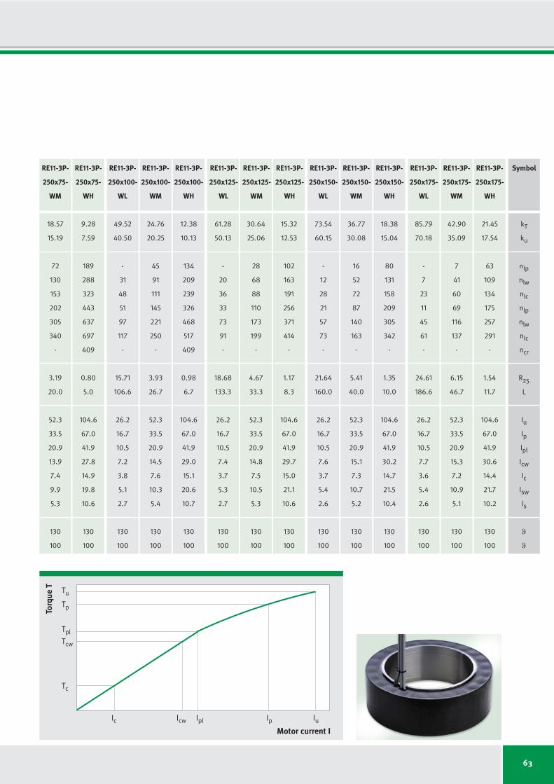
63
49.52
40.50
-
31
48
51
97
117
-
15.71
106.6
26.2
16.7
10.5
7.2
3.8
5.1
2.7
130
100
24.76
20.25
45
91
111
145
221
250
-
3.93
26.7
52.3
33.5
20.9
14.5
7.6
10.3
5.4
130
100
12.38
10.13
134
209
239
326
468
517
409
0.98
6.7
104.6
67.0
41.9
29.0
15.1
20.6
10.7
130
100
61.28
50.13
-
20
36
33
73
91
-
18.68
133.3
26.2
16.7
10.5
7.4
3.7
5.3
2.7
130
100
30.64
25.06
28
68
88
110
173
199
-
4.67
33.3
52.3
33.5
20.9
14.8
7.5
10.5
5.3
130
100
15.32
12.53
102
163
191
256
371
414
-
1.17
8.3
104.6
67.0
41.9
29.7
15.0
21.1
10.6
130
100
73.54
60.15
-
12
28
21
57
73
-
21.64
160.0
26.2
16.7
10.5
7.6
3.7
5.4
2.6
130
100
36.77
30.08
16
52
72
87
140
163
-
5.41
40.0
52.3
33.5
20.9
15.1
7.3
10.7
5.2
130
100
18.38
15.04
80
131
158
209
305
342
-
1.35
10.0
104.6
67.0
41.9
30.2
14.7
21.5
10.4
130
100
85.79
70.18
-
7
23
11
45
61
-
24.61
186.6
26.2
16.7
10.5
7.7
3.6
5.4
2.6
130
100
42.90
35.09
7
41
60
69
116
137
-
6.15
46.7
52.3
33.5
20.9
15.3
7.2
10.9
5.1
130
100
21.45
17.54
63
109
134
175
257
291
-
1.54
11.7
104.6
67.0
41.9
30.6
14.4
21.7
10.2
130
100
RE11-3P-
250x100-
WL
RE11-3P-
250x100-
WM
RE11-3P-
250x100-
WH
RE11-3P-
250x125-
WL
RE11-3P-
250x125-
WM
RE11-3P-
250x125-
WH
RE11-3P-
250x150-
WL
RE11-3P-
250x150-
WM
RE11-3P-
250x150-
WH
RE11-3P-
250x175-
WL
RE11-3P-
250x175-
WM
RE11-3P-
250x175-
WH
Torq
ue T
Motor current I
Tc
Icw IplIc Ip Iu
Tcw
Tpl
Tp
Tu
18.57
15.19
72
130
153
202
305
340
-
3.19
20.0
52.3
33.5
20.9
13.9
7.4
9.9
5.3
130
100
9.28
7.59
189
288
323
443
637
697
409
0.80
5.0
104.6
67.0
41.9
27.8
14.9
19.8
10.6
130
100
RE11-3P-
250x75-
WM
RE11-3P-
250x75-
WH
Symbol
kT
ku
nlp
nlw
nlc
nlp
nlw
nlc
ncr
R25
L
Iu
Ip
Ipl
Icw
Ic
Isw
Is
ϑ
ϑ
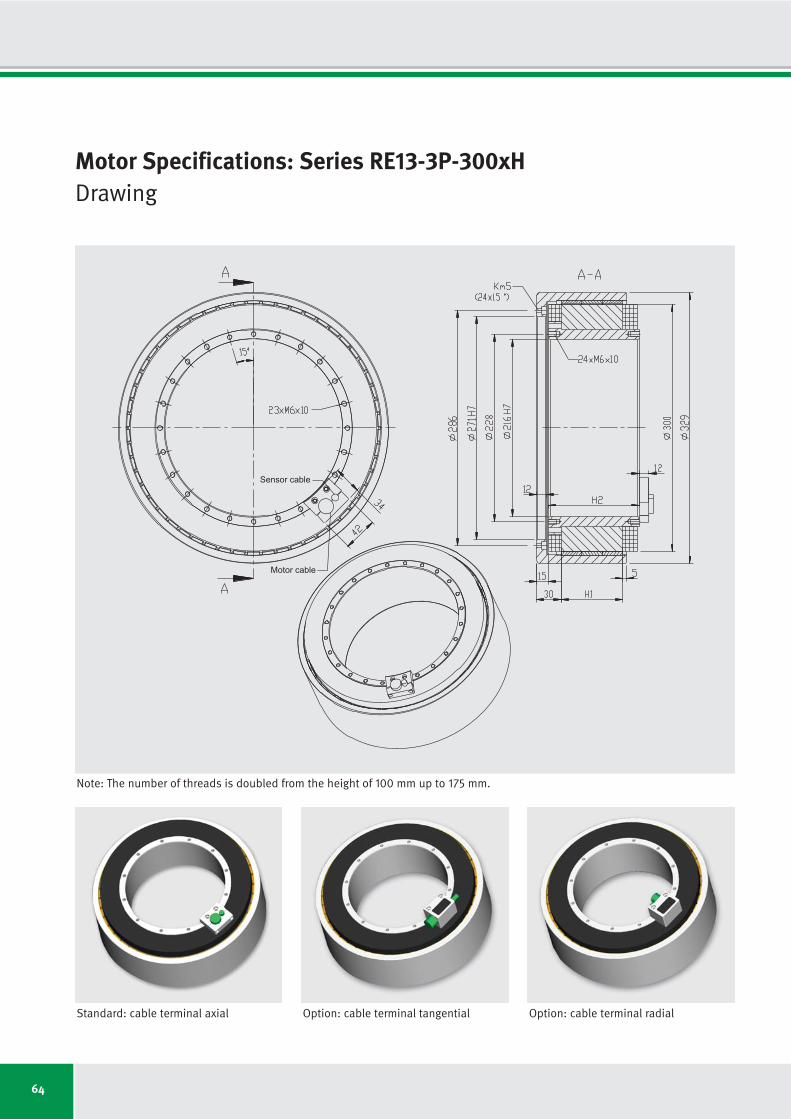
64
Motor Specifications: Series RE13-3P-300xHDrawing
Sensor cable
Motor cable
Standard: cable terminal axial Option: cable terminal tangential Option: cable terminal radial
Note: The number of threads is doubled from the height of 100 mm up to 175 mm.

65
Motor Specifications Symbol Unit RE13-3P- RE13-3P- RE13-3P- RE13-3P- RE13-3P- RE13-3P- RE13-3P-
300x25 300x50 300x75 300x100 300x125 300x150 300x175
Number of pole pairs P
Maximum operating voltage UDCL VDC
Ultimate torque at Iu Tu Nm
Peak torque (saturation range) at Ip Tp Nm
Peak torque (linear range) at Ipl Tpl Nm
Continuous torque (water cooled) at Icw Tcw Nm
Continuous torque (not cooled) at Ic Tc Nm
Stall torque (water cooled) at Isw Tsw Nm
Stall torque (not cooled) at Is Ts Nm
Ripple torque (cogging) at I = 0 Tr Nm
Power loss (copper) at Tp (statical at 25 °C) Plp W
Power loss (copper) at Tpl (statical at 25 °C) Plpl W
Power loss (copper) at Tcw (statical at 100 °C) Plw W
Power loss (copper) at Tc (statical at 25 °C) Plc W
Thermical resistance (water cooled) Rth K/W
Motor constant (at 25 °C; valid up to Ipl) km Nm/√W
Water flow (cooling) dV/dt l/min
Water temperature difference (cooling) Δϑ K
Mechanical interface Symbol Unit RE13-3P- RE13-3P- RE13-3P- RE13-3P- RE13-3P- RE13-3P- RE13-3P-
300x25 300x50 300x75 300x100 300x125 300x150 300x175
Height of rotor H1
mm
Height of stator H2
mm
Mass of rotor m1
kg
Mass of stator m2
kg
Inertia of rotor J kgm2
26
600
308
244
158
97
53
69
37
0.7
3489
1058
518
118
0.193
4.86
1.48
5.00
25.0
60.0
6.7
11.9
0.1629
50.0
85.0
9.2
17.8
0.2244
75.0
110.0
11.6
23.7
0.2859
100.0
135.0
14.1
29.9
0.3474
125.0
160.0
16.5
35.8
0.4089
150.0
185.0
19.0
41.7
0.4704
175.0
210.0
21.4
47.6
0.5319
26
600
617
488
316
231
122
164
86
1.5
4943
1498
1036
221
0.097
8.17
2.96
5.00
26
600
916
725
470
369
190
262
135
2.2
6396
1939
1554
318
0.064
10.67
4.44
5.00
26
600
1221
967
626
513
258
364
183
2.9
7850
2380
2072
405
0.048
12.84
5.92
5.00
26
600
1511
1197
775
651
317
463
225
3.6
9304
2821
2591
471
0.039
14.59
7.40
5.00
26
600
1814
1436
930
796
372
565
264
4.3
10758
3261
3109
523
0.032
16.29
8.88
5.00
26
600
2094
1658
1074
932
424
662
301
5.0
12211
3702
3627
577
0.028
17.65
10.36
5.00
Motor Specifications: Series RE13-3P-300xHIndependent of winding
Subject to modification without previous notice. • Tolerance range for values: ±5% • Tolerance range for value “power loss”: ±10%
IDAM will provide additional specifications and drawings per customer request. IDAM recommends that all motor applications be reviewed by an IDAM specialist.
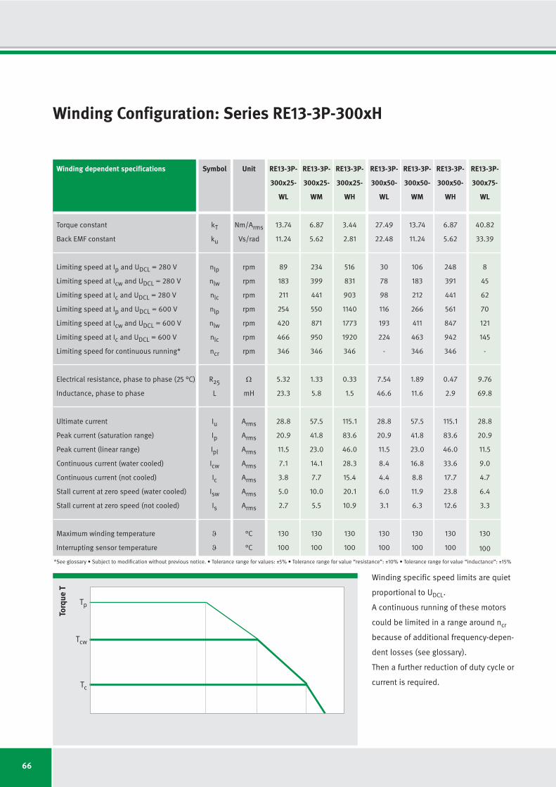
66
13.74
11.24
89
183
211
254
420
466
346
5.32
23.3
28.8
20.9
11.5
7.1
3.8
5.0
2.7
130
100
6.87
5.62
234
399
441
550
871
950
346
1.33
5.8
57.5
41.8
23.0
14.1
7.7
10.0
5.5
130
100
3.44
2.81
516
831
903
1140
1773
1920
346
0.33
1.5
115.1
83.6
46.0
28.3
15.4
20.1
10.9
130
100
27.49
22.48
30
78
98
116
193
224
-
7.54
46.6
28.8
20.9
11.5
8.4
4.4
6.0
3.1
130
100
13.74
11.24
106
183
212
266
411
463
346
1.89
11.6
57.5
41.8
23.0
16.8
8.8
11.9
6.3
130
100
6.87
5.62
248
391
441
561
847
942
346
0.47
2.9
115.1
83.6
46.0
33.6
17.7
23.8
12.6
130
100
RE13-3P-
300x25-
WL
RE13-3P-
300x25-
WM
RE13-3P-
300x25-
WH
RE13-3P-
300x50-
WL
RE13-3P-
300x50-
WM
RE13-3P-
300x50-
WH
Winding Configuration: Series RE13-3P-300xH
Winding dependent specifications
Torque constant
Back EMF constant
Limiting speed at Ip and UDCL = 280 V
Limiting speed at Icw and UDCL = 280 V
Limiting speed at Ic and UDCL = 280 V
Limiting speed at Ip and UDCL = 600 V
Limiting speed at Icw and UDCL = 600 V
Limiting speed at Ic and UDCL = 600 V
Limiting speed for continuous running*
Electrical resistance, phase to phase (25 °C)
Inductance, phase to phase
Ultimate current
Peak current (saturation range)
Peak current (linear range)
Continuous current (water cooled)
Continuous current (not cooled)
Stall current at zero speed (water cooled)
Stall current at zero speed (not cooled)
Maximum winding temperature
Interrupting sensor temperature
Symbol
kT
ku
nlp
nlw
nlc
nlp
nlw
nlc
ncr
R25
L
Iu
Ip
Ipl
Icw
Ic
Isw
Is
ϑ
ϑ
*See glossary • Subject to modification without previous notice. • Tolerance range for values: ±5% • Tolerance range for value “resistance”: ±10% • Tolerance range for value “inductance”: ±15%
Unit
Nm/Arms
Vs/rad
rpm
rpm
rpm
rpm
rpm
rpm
rpm
Ω
mH
Arms
Arms
Arms
Arms
Arms
Arms
Arms
°C
°C
Winding specific speed limits are quiet
proportional to UDCL.
A continuous running of these motors
could be limited in a range around ncr
because of additional frequency-depen-
dent losses (see glossary).
Then a further reduction of duty cycle or
current is required.
Torq
ue T
Tc
Tcw
Tp
40.82
33.39
8
45
62
70
121
145
-
9.76
69.8
28.8
20.9
11.5
9.0
4.7
6.4
3.3
130
100
RE13-3P-
300x75-
WL
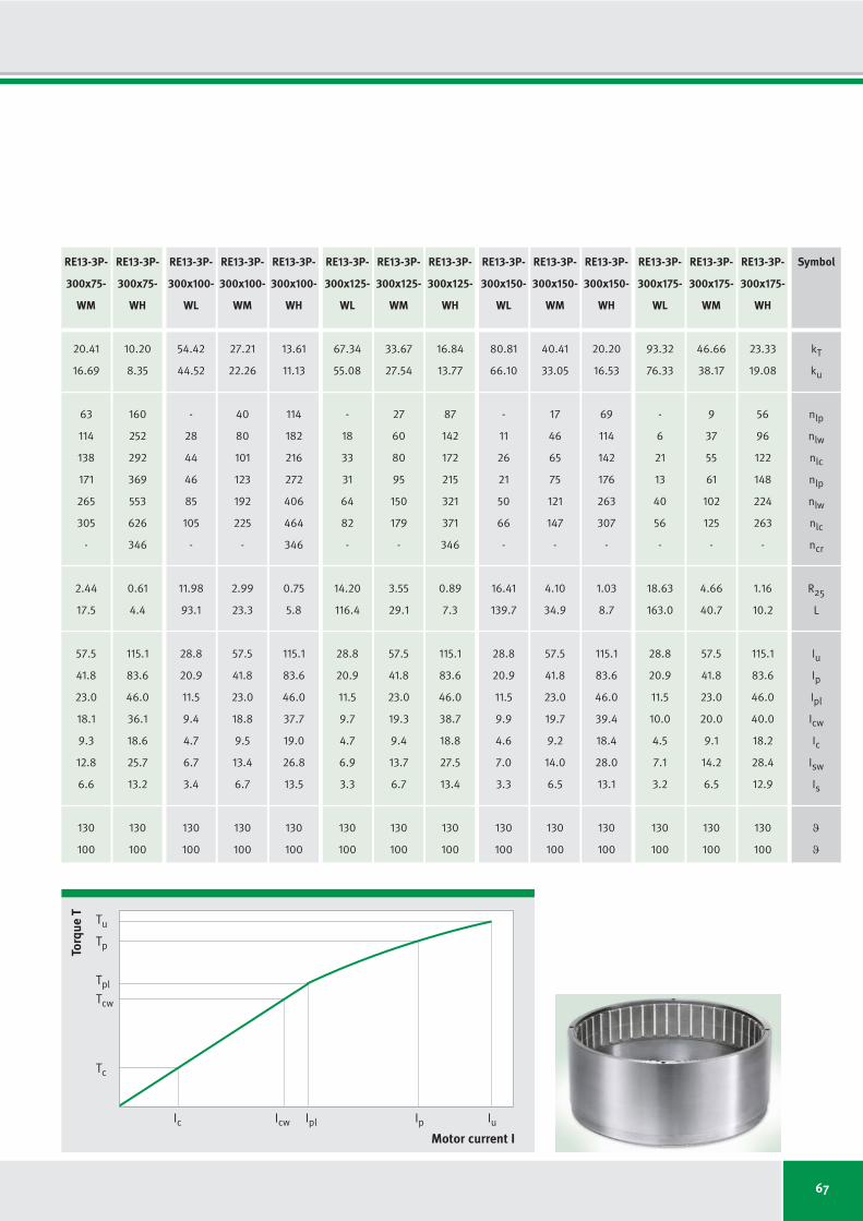
67
54.42
44.52
-
28
44
46
85
105
-
11.98
93.1
28.8
20.9
11.5
9.4
4.7
6.7
3.4
130
100
27.21
22.26
40
80
101
123
192
225
-
2.99
23.3
57.5
41.8
23.0
18.8
9.5
13.4
6.7
130
100
13.61
11.13
114
182
216
272
406
464
346
0.75
5.8
115.1
83.6
46.0
37.7
19.0
26.8
13.5
130
100
67.34
55.08
-
18
33
31
64
82
-
14.20
116.4
28.8
20.9
11.5
9.7
4.7
6.9
3.3
130
100
33.67
27.54
27
60
80
95
150
179
-
3.55
29.1
57.5
41.8
23.0
19.3
9.4
13.7
6.7
130
100
16.84
13.77
87
142
172
215
321
371
346
0.89
7.3
115.1
83.6
46.0
38.7
18.8
27.5
13.4
130
100
80.81
66.10
-
11
26
21
50
66
-
16.41
139.7
28.8
20.9
11.5
9.9
4.6
7.0
3.3
130
100
40.41
33.05
17
46
65
75
121
147
-
4.10
34.9
57.5
41.8
23.0
19.7
9.2
14.0
6.5
130
100
20.20
16.53
69
114
142
176
263
307
-
1.03
8.7
115.1
83.6
46.0
39.4
18.4
28.0
13.1
130
100
93.32
76.33
-
6
21
13
40
56
-
18.63
163.0
28.8
20.9
11.5
10.0
4.5
7.1
3.2
130
100
46.66
38.17
9
37
55
61
102
125
-
4.66
40.7
57.5
41.8
23.0
20.0
9.1
14.2
6.5
130
100
23.33
19.08
56
96
122
148
224
263
-
1.16
10.2
115.1
83.6
46.0
40.0
18.2
28.4
12.9
130
100
RE13-3P-
300x100-
WL
RE13-3P-
300x100-
WM
RE13-3P-
300x100-
WH
RE13-3P-
300x125-
WL
RE13-3P-
300x125-
WM
RE13-3P-
300x125-
WH
RE13-3P-
300x150-
WL
RE13-3P-
300x150-
WM
RE13-3P-
300x150-
WH
RE13-3P-
300x175-
WL
RE13-3P-
300x175-
WM
RE13-3P-
300x175-
WH
Torq
ue T
Motor current I
Tc
Icw IplIc Ip Iu
Tcw
Tpl
Tp
Tu
20.41
16.69
63
114
138
171
265
305
-
2.44
17.5
57.5
41.8
23.0
18.1
9.3
12.8
6.6
130
100
10.20
8.35
160
252
292
369
553
626
346
0.61
4.4
115.1
83.6
46.0
36.1
18.6
25.7
13.2
130
100
RE13-3P-
300x75-
WM
RE13-3P-
300x75-
WH
Symbol
kT
ku
nlp
nlw
nlc
nlp
nlw
nlc
ncr
R25
L
Iu
Ip
Ipl
Icw
Ic
Isw
Is
ϑ
ϑ

68
Motor Specifications: Series RE11-3P-360xHDrawing
Sensor cable
Motor cable
Standard: cable terminal axial Option: cable terminal tangential Option: cable terminal radial
Note: The number of threads is doubled from the height of 100 mm up to 175 mm.

69
Motor specifications Symbol Unit RE11-3P- RE11-3P- RE11-3P- RE11-3P- RE11-3P- RE11-3P- RE11-3P-
360x25 360x50 360x75 360x100 360x125 360x150 360x175
Number of pole pairs P
Maximum operating voltage UDCL VDC
Ultimate torque at Iu Tu Nm
Peak torque (saturation range) at Ip Tp Nm
Peak torque (linear range) at Ipl Tpl Nm
Continuous torque (water cooled) at Icw Tcw Nm
Continuous torque (not cooled) at Ic Tc Nm
Stall torque (water cooled) at Isw Tsw Nm
Stall torque (not cooled) at Is Ts Nm
Ripple torque (cogging) at I = 0 Tr Nm
Power loss (copper) at Tp (statical at 25 °C) Plp W
Power loss (copper) at Tpl (statical at 25 °C) Plpl W
Power loss (copper) at Tcw (statical at 100 °C) Plw W
Power loss (copper) at Tc (statical at 25 °C) Plc W
Thermical resistance (water cooled) Rth K/W
Motor constant (at 25 °C; valid up to Ipl) km Nm/√W
Water flow (cooling) dV/dt l/min
Water temperature difference (cooling) Δϑ K
Mechanical interface Symbol Unit RE11-3P- RE11-3P- RE11-3P- RE11-3P- RE11-3P- RE11-3P- RE11-3P-
360x25 360x50 360x75 360x100 360x125 360x150 360x175
Height of rotor H1
mm
Height of stator H2
mm
Mass of rotor m1
kg
Mass of stator m2
kg
Inertia of rotor J kgm2
33
600
467
437
267
160
86
114
61
1.3
5395
1349
630
141
0.159
7.26
1.80
5.00
25.0
60.0
9.5
15.8
0.3188
50.0
85.0
12.4
23.7
0.4234
75.0
110.0
15.4
31.6
0.5280
100.0
135.0
18.4
39.5
0.6326
125.0
160.0
21.3
48.0
0.7372
150.0
185.0
24.3
56.0
0.8418
175.0
210.0
27.2
63.9
0.9464
33
600
924
866
528
374
196
265
139
2.6
7740
1935
1261
266
0.079
12.00
3.60
5.00
33
600
1372
1285
784
595
305
423
216
3.9
10086
2521
1891
382
0.053
15.61
5.40
5.00
33
600
1829
1714
1045
826
413
586
293
5.1
12431
3108
2521
486
0.040
18.74
7.20
5.00
33
600
2262
2120
1293
1047
506
744
359
6.4
14777
3694
3152
565
0.032
21.27
9.01
5.00
33
600
2715
2544
1551
1279
594
908
422
7.6
17122
4281
3782
627
0.026
23.71
10.81
5.00
33
600
3167
2968
1810
1511
683
1073
485
8.9
19468
4867
4412
692
0.023
25.94
12.61
5.00
Motor Specifications: Series RE11-3P-360xHIndependent of winding
Subject to modification without previous notice. • Tolerance range for values: ±5% • Tolerance range for value “power loss”: ±10%
IDAM will provide additional specifications and drawings per customer request. IDAM recommends that all motor applications be reviewed by an IDAM specialist.

70
12.35
10.10
109
216
242
273
483
527
273
1.93
8.9
54.0
43.2
21.6
12.9
7.0
9.2
5.0
130
100
8.24
6.74
184
337
371
426
736
797
273
0.86
3.9
80.9
64.8
32.4
19.4
10.5
13.8
7.4
130
100
4.12
3.37
403
698
756
884
1497
1610
273
0.21
1.0
161.9
129.5
64.8
38.8
21.0
27.6
14.9
130
100
24.46
20.00
45
98
117
129
228
258
-
2.77
17.8
54.0
43.2
21.6
15.3
8.0
10.8
5.7
130
100
16.30
13.34
83
157
181
206
351
393
273
1.23
7.9
80.9
64.8
32.4
22.9
12.0
16.3
8.5
130
100
8.15
6.67
195
333
374
437
722
798
273
0.31
2.0
161.9
129.5
64.8
45.8
24.0
32.5
17.0
130
100
RE11-3P-
360x25-
WL
RE11-3P-
360x25-
WM
RE11-3P-
360x25-
WH
RE11-3P-
360x50-
WL
RE11-3P-
360x50-
WM
RE11-3P-
360x50-
WH
Winding Configuration: Series RE11-3P-360xH
Winding dependent specifications
Torque constant
Back EMF constant
Limiting speed at Ip and UDCL = 280 V
Limiting speed at Icw and UDCL = 280 V
Limiting speed at Ic and UDCL = 280 V
Limiting speed at Ip and UDCL = 600 V
Limiting speed at Icw and UDCL = 600 V
Limiting speed at Ic and UDCL = 600 V
Limiting speed for continuous running*
Electrical resistance, phase to phase (25 °C)
Inductance, phase to phase
Ultimate current
Peak current (saturation range)
Peak current (linear range)
Continuous current (water cooled)
Continuous current (not cooled)
Stall current at zero speed (water cooled)
Stall current at zero speed (not cooled)
Maximum winding temperature
Interrupting sensor temperature
Symbol
kT
ku
nlp
nlw
nlc
nlp
nlw
nlc
ncr
R25
L
Iu
Ip
Ipl
Icw
Ic
Isw
Is
ϑ
ϑ
*See glossary • Subject to modification without previous notice. • Tolerance range for values: ±5% • Tolerance range for value “resistance”: ±10% • Tolerance range for value “inductance”: ±15%
Unit
Nm/Arms
Vs/rad
rpm
rpm
rpm
rpm
rpm
rpm
rpm
Ω
mH
Arms
Arms
Arms
Arms
Arms
Arms
Arms
°C
°C
Winding specific speed limits are quiet
proportional to UDCL.
A continuous running of these motors
could be limited in a range around ncr
because of additional frequency-depen-
dent losses (see glossary).
Then a further reduction of duty cycle or
current is required.
Torq
ue T
Tc
Tcw
Tp
36.31
29.70
22
60
75
81
146
169
-
3.61
26.7
54.0
43.2
21.6
16.4
8.4
11.6
6.0
130
100
RE11-3P-
360x75-
WL

71
48.41
39.60
9
40
54
56
104
124
-
4.45
35.5
54.0
43.2
21.6
17.1
8.5
12.1
6.1
130
100
32.27
26.40
32
69
87
96
165
192
-
1.98
15.8
80.9
64.8
32.4
25.6
12.8
18.2
9.1
130
100
16.14
13.20
90
156
183
212
347
394
273
0.49
3.9
161.9
129.5
64.8
51.2
25.6
36.3
18.2
130
100
59.89
48.99
-
29
42
41
81
98
-
5.29
44.4
54.0
43.2
21.6
17.5
8.4
12.4
6.0
130
100
39.93
32.66
21
53
68
73
129
152
-
2.35
19.7
80.9
64.8
32.4
26.2
12.7
18.6
9.0
130
100
19.96
16.33
68
122
147
167
275
316
273
0.59
4.9
161.9
129.5
64.8
52.5
25.3
37.2
18.0
130
100
71.87
58.79
-
22
34
30
64
80
-
6.13
53.3
54.0
43.2
21.6
17.8
8.3
12.6
5.9
130
100
47.91
39.19
13
41
56
58
105
125
-
2.72
23.7
80.9
64.8
32.4
26.7
12.4
19.0
8.8
130
100
23.96
19.60
54
99
121
137
226
261
-
0.68
5.9
161.9
129.5
64.8
53.4
24.8
37.9
17.6
130
100
83.85
68.59
-
16
28
23
53
67
-
6.96
62.2
54.0
43.2
21.6
18.0
8.1
12.8
5.8
130
100
55.90
45.72
6
33
47
47
87
106
-
3.10
27.6
80.9
64.8
32.4
27.0
12.2
19.2
8.7
130
100
27.95
22.86
43
82
103
115
191
222
-
0.77
6.9
161.9
129.5
64.8
54.1
24.4
38.4
17.3
130
100
RE11-3P-
360x100-
WL
RE11-3P-
360x100-
WM
RE11-3P-
360x100-
WH
RE11-3P-
360x125-
WL
RE11-3P-
360x125-
WM
RE11-3P-
360x125-
WH
RE11-3P-
360x150-
WL
RE11-3P-
360x150-
WM
RE11-3P-
360x150-
WH
RE11-3P-
360x175-
WL
RE11-3P-
360x175-
WM
RE11-3P-
360x175-
WH
Torq
ue T
Motor current I
Tc
Icw IplIc Ip Iu
Tcw
Tpl
Tp
Tu
24.21
19.80
49
98
118
133
227
260
-
1.60
11.8
80.9
64.8
32.4
24.6
12.6
17.5
8.9
130
100
12.10
9.90
125
215
248
287
472
531
273
0.40
3.0
161.9
129.5
64.8
49.2
25.2
34.9
17.9
130
100
RE11-3P-
360x75-
WM
RE11-3P-
360x75-
WH
Symbol
kT
ku
nlp
nlw
nlc
nlp
nlw
nlc
ncr
R25
L
Iu
Ip
Ipl
Icw
Ic
Isw
Is
ϑ
ϑ
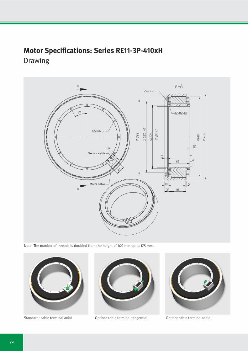
72
Motor Specifications: Series RE11-3P-410xHDrawing
Sensor cable
Motor cable
Standard: cable terminal axial Option: cable terminal tangential Option: cable terminal radial
Note: The number of threads is doubled from the height of 100 mm up to 175 mm.

73
Motor specifications Symbol Unit RE11-3P- RE11-3P- RE11-3P- RE11-3P- RE11-3P- RE11-3P- RE11-3P-
410x25 410x50 410x75 410x100 410x125 410x150 410x175
Number of pole pairs P
Maximum operating voltage UDCL VDC
Ultimate torque at Iu Tu Nm
Peak torque (saturation range) at Ip Tp Nm
Peak torque (linear range) at Ipl Tpl Nm
Continuous torque (water cooled) at Icw Tcw Nm
Continuous torque (not cooled) at Ic Tc Nm
Stall torque (water cooled) at Isw Tsw Nm
Stall torque (not cooled) at Is Ts Nm
Ripple torque (cogging) at I = 0 Tr Nm
Power loss (copper) at Tp (statical at 25 °C) Plp W
Power loss (copper) at Tpl (statical at 25 °C) Plpl W
Power loss (copper) at Tcw (statical at 100 °C) Plw W
Power loss (copper) at Tc (statical at 25 °C) Plc W
Thermical resistance (water cooled) Rth K/W
Motor constant (at 25 °C; valid up to Ipl) km Nm/√W
Water flow (cooling) dV/dt l/min
Water temperature difference (cooling) Δϑ K
Mechanical interface Symbol Unit RE11-3P- RE11-3P- RE11-3P- RE11-3P- RE11-3P- RE11-3P- RE11-3P-
410x25 410x50 410x75 410x100 410x125 410x150 410x175
Height of rotor H1
mm
Height of stator H2
mm
Mass of rotor m1
kg
Mass of stator m2
kg
Inertia of rotor J kgm2
33
600
586
439
335
214
115
152
81
1.3
3521
1376
730
161
0.137
9.03
2.08
5.00
25.0
60.0
11.0
19.8
0.4762
50.0
85.0
14.3
29.7
0.6247
75.0
110.0
17.6
39.6
0.7732
100.0
135.0
20.8
49.6
0.9217
125.0
160.0
24.1
59.5
1.0702
150.0
185.0
27.3
70.1
1.2187
175.0
210.0
30.6
80.0
1.3672
33
600
1172
879
670
505
262
359
186
2.6
5052
1974
1459
303
0.069
15.08
4.17
5.00
33
600
1741
1305
995
805
409
571
290
3.9
6583
2572
2189
434
0.046
19.61
6.25
5.00
33
600
2321
1740
1326
1116
554
792
393
5.2
8114
3170
2919
554
0.034
23.55
8.34
5.00
33
600
2871
2152
1641
1416
678
1005
481
6.5
9646
3768
3648
644
0.027
26.73
10.42
5.00
33
600
3445
2583
1969
1729
796
1228
565
7.7
11177
4366
4378
715
0.023
29.79
12.51
5.00
33
600
4019
3013
2297
2043
915
1451
650
9.0
12708
4964
5108
789
0.020
32.60
14.59
5.00
Motor Specifications: Series RE11-3P-410xHIndependent of winding
Subject to modification without previous notice. • Tolerance range for values: ±5% • Tolerance range for value “power loss”: ±10%
IDAM will provide additional specifications and drawings per customer request. IDAM recommends that all motor applications be reviewed by an IDAM specialist.
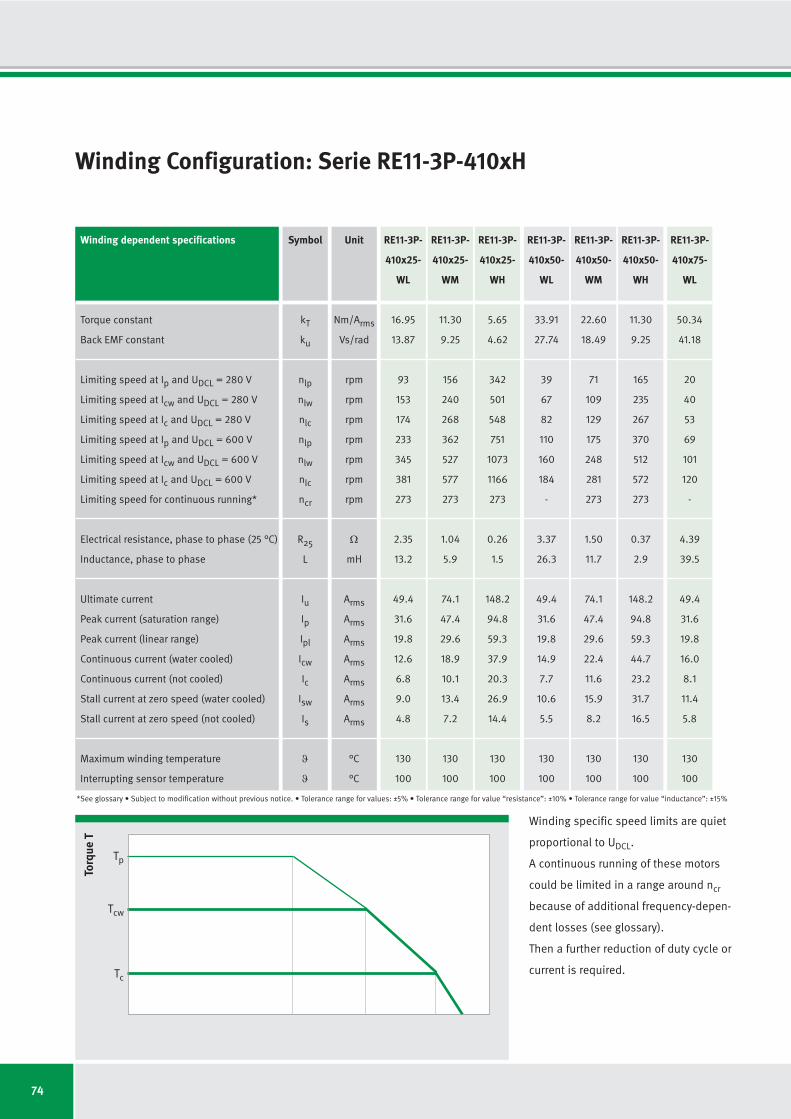
74
16.95
13.87
93
153
174
233
345
381
273
2.35
13.2
49.4
31.6
19.8
12.6
6.8
9.0
4.8
130
100
11.30
9.25
156
240
268
362
527
577
273
1.04
5.9
74.1
47.4
29.6
18.9
10.1
13.4
7.2
130
100
5.65
4.62
342
501
548
751
1073
1166
273
0.26
1.5
148.2
94.8
59.3
37.9
20.3
26.9
14.4
130
100
33.91
27.74
39
67
82
110
160
184
-
3.37
26.3
49.4
31.6
19.8
14.9
7.7
10.6
5.5
130
100
22.60
18.49
71
109
129
175
248
281
273
1.50
11.7
74.1
47.4
29.6
22.4
11.6
15.9
8.2
130
100
11.30
9.25
165
235
267
370
512
572
273
0.37
2.9
148.2
94.8
59.3
44.7
23.2
31.7
16.5
130
100
RE11-3P-
410x25-
WL
RE11-3P-
410x25-
WM
RE11-3P-
410x25-
WH
RE11-3P-
410x50-
WL
RE11-3P-
410x50-
WM
RE11-3P-
410x50-
WH
Winding Configuration: Serie RE11-3P-410xH
Winding dependent specifications
Torque constant
Back EMF constant
Limiting speed at Ip and UDCL = 280 V
Limiting speed at Icw and UDCL = 280 V
Limiting speed at Ic and UDCL = 280 V
Limiting speed at Ip and UDCL = 600 V
Limiting speed at Icw and UDCL = 600 V
Limiting speed at Ic and UDCL = 600 V
Limiting speed for continuous running*
Electrical resistance, phase to phase (25 °C)
Inductance, phase to phase
Ultimate current
Peak current (saturation range)
Peak current (linear range)
Continuous current (water cooled)
Continuous current (not cooled)
Stall current at zero speed (water cooled)
Stall current at zero speed (not cooled)
Maximum winding temperature
Interrupting sensor temperature
Symbol
kT
ku
nlp
nlw
nlc
nlp
nlw
nlc
ncr
R25
L
Iu
Ip
Ipl
Icw
Ic
Isw
Is
ϑ
ϑ
*See glossary • Subject to modification without previous notice. • Tolerance range for values: ±5% • Tolerance range for value “resistance”: ±10% • Tolerance range for value “inductance”: ±15%
Unit
Nm/Arms
Vs/rad
rpm
rpm
rpm
rpm
rpm
rpm
rpm
Ω
mH
Arms
Arms
Arms
Arms
Arms
Arms
Arms
°C
°C
Winding specific speed limits are quiet
proportional to UDCL.
A continuous running of these motors
could be limited in a range around ncr
because of additional frequency-depen-
dent losses (see glossary).
Then a further reduction of duty cycle or
current is required.
Torq
ue T
Tc
Tcw
Tp
50.34
41.18
20
40
53
69
101
120
-
4.39
39.5
49.4
31.6
19.8
16.0
8.1
11.4
5.8
130
100
RE11-3P-
410x75-
WL
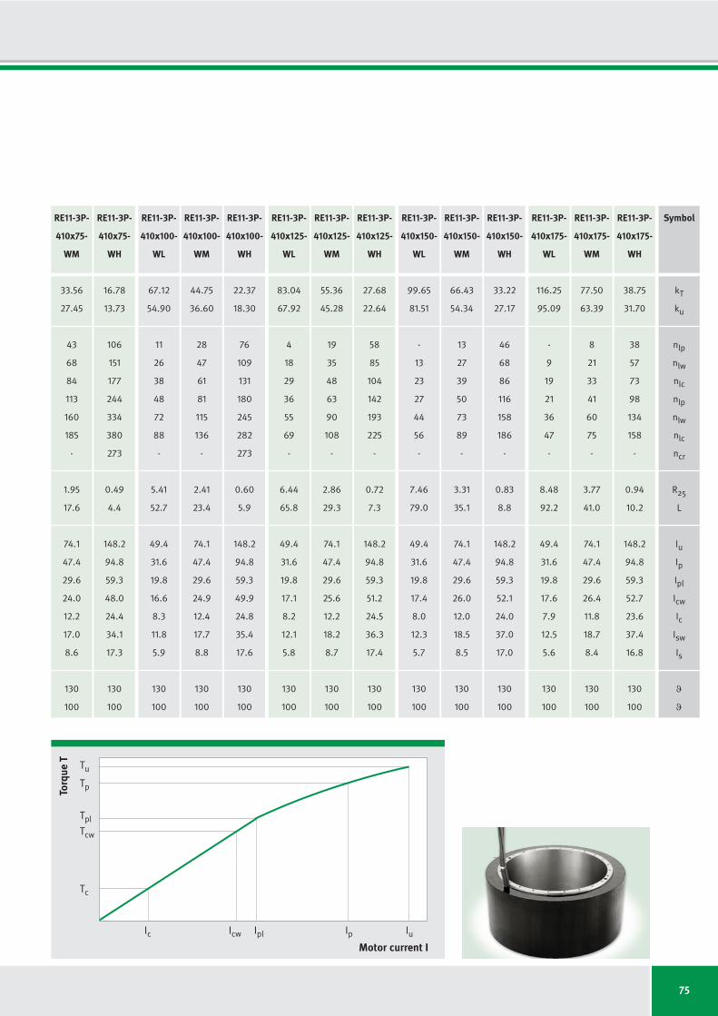
75
67.12
54.90
11
26
38
48
72
88
-
5.41
52.7
49.4
31.6
19.8
16.6
8.3
11.8
5.9
130
100
44.75
36.60
28
47
61
81
115
136
-
2.41
23.4
74.1
47.4
29.6
24.9
12.4
17.7
8.8
130
100
22.37
18.30
76
109
131
180
245
282
273
0.60
5.9
148.2
94.8
59.3
49.9
24.8
35.4
17.6
130
100
83.04
67.92
4
18
29
36
55
69
-
6.44
65.8
49.4
31.6
19.8
17.1
8.2
12.1
5.8
130
100
55.36
45.28
19
35
48
63
90
108
-
2.86
29.3
74.1
47.4
29.6
25.6
12.2
18.2
8.7
130
100
27.68
22.64
58
85
104
142
193
225
-
0.72
7.3
148.2
94.8
59.3
51.2
24.5
36.3
17.4
130
100
99.65
81.51
-
13
23
27
44
56
-
7.46
79.0
49.4
31.6
19.8
17.4
8.0
12.3
5.7
130
100
66.43
54.34
13
27
39
50
73
89
-
3.31
35.1
74.1
47.4
29.6
26.0
12.0
18.5
8.5
130
100
33.22
27.17
46
68
86
116
158
186
-
0.83
8.8
148.2
94.8
59.3
52.1
24.0
37.0
17.0
130
100
116.25
95.09
-
9
19
21
36
47
-
8.48
92.2
49.4
31.6
19.8
17.6
7.9
12.5
5.6
130
100
77.50
63.39
8
21
33
41
60
75
-
3.77
41.0
74.1
47.4
29.6
26.4
11.8
18.7
8.4
130
100
38.75
31.70
38
57
73
98
134
158
-
0.94
10.2
148.2
94.8
59.3
52.7
23.6
37.4
16.8
130
100
RE11-3P-
410x100-
WL
RE11-3P-
410x100-
WM
RE11-3P-
410x100-
WH
RE11-3P-
410x125-
WL
RE11-3P-
410x125-
WM
RE11-3P-
410x125-
WH
RE11-3P-
410x150-
WL
RE11-3P-
410x150-
WM
RE11-3P-
410x150-
WH
RE11-3P-
410x175-
WL
RE11-3P-
410x175-
WM
RE11-3P-
410x175-
WH
Torq
ue T
Motor current I
Tc
Icw IplIc Ip Iu
Tcw
Tpl
Tp
Tu
33.56
27.45
43
68
84
113
160
185
-
1.95
17.6
74.1
47.4
29.6
24.0
12.2
17.0
8.6
130
100
16.78
13.73
106
151
177
244
334
380
273
0.49
4.4
148.2
94.8
59.3
48.0
24.4
34.1
17.3
130
100
RE11-3P-
410x75-
WM
RE11-3P-
410x75-
WH
Symbol
kT
ku
nlp
nlw
nlc
nlp
nlw
nlc
ncr
R25
L
Iu
Ip
Ipl
Icw
Ic
Isw
Is
ϑ
ϑ

76
Motor Specifications: Series RE11-3P-530xHDrawing
Sensor cable
Motor cable
Standard: cable terminal axial Option: cable terminal tangential Option: cable terminal radial
Note: The number of threads is doubled from the height of 100 mm up to 175 mm.
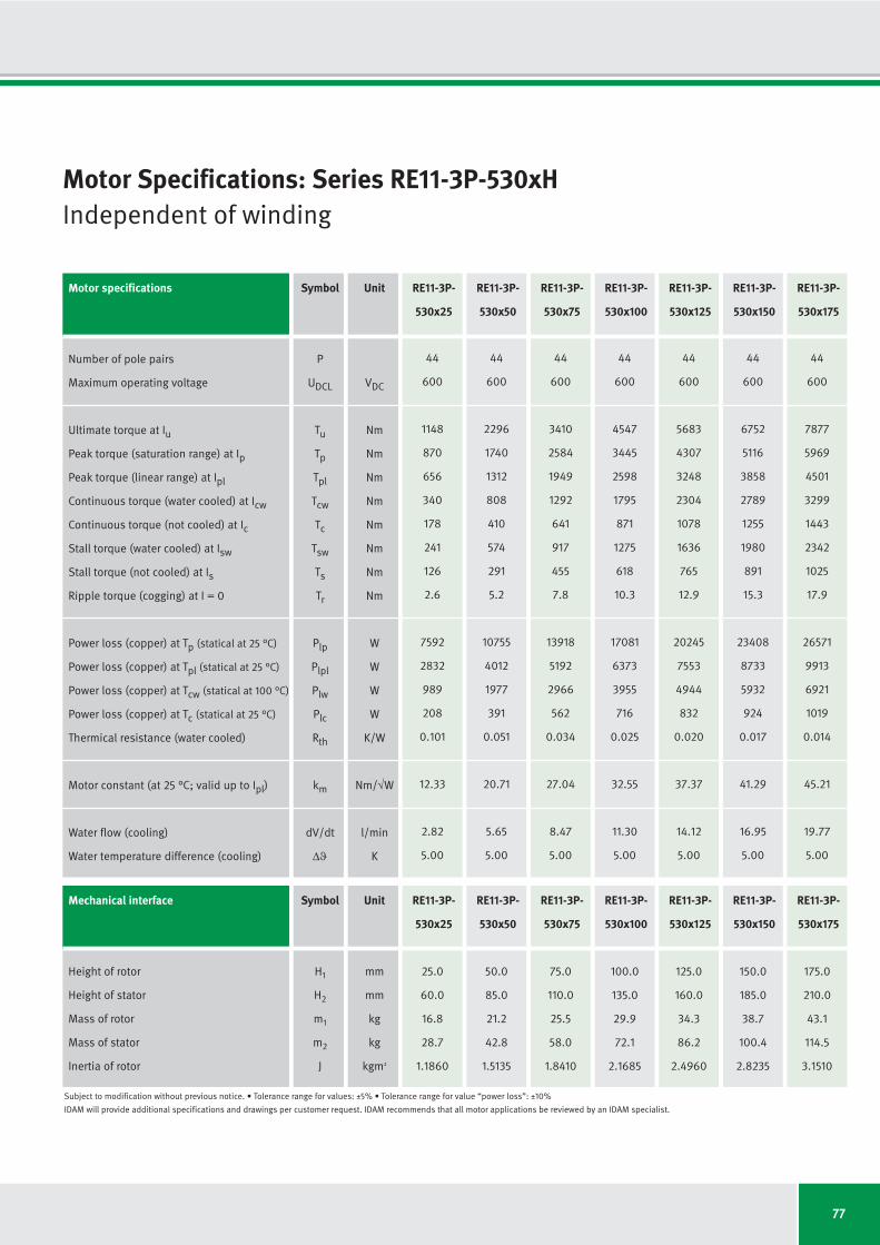
77
Motor specifications Symbol Unit RE11-3P- RE11-3P- RE11-3P- RE11-3P- RE11-3P- RE11-3P- RE11-3P-
530x25 530x50 530x75 530x100 530x125 530x150 530x175
Number of pole pairs P
Maximum operating voltage UDCL VDC
Ultimate torque at Iu Tu Nm
Peak torque (saturation range) at Ip Tp Nm
Peak torque (linear range) at Ipl Tpl Nm
Continuous torque (water cooled) at Icw Tcw Nm
Continuous torque (not cooled) at Ic Tc Nm
Stall torque (water cooled) at Isw Tsw Nm
Stall torque (not cooled) at Is Ts Nm
Ripple torque (cogging) at I = 0 Tr Nm
Power loss (copper) at Tp (statical at 25 °C) Plp W
Power loss (copper) at Tpl (statical at 25 °C) Plpl W
Power loss (copper) at Tcw (statical at 100 °C) Plw W
Power loss (copper) at Tc (statical at 25 °C) Plc W
Thermical resistance (water cooled) Rth K/W
Motor constant (at 25 °C; valid up to Ipl) km Nm/√W
Water flow (cooling) dV/dt l/min
Water temperature difference (cooling) Δϑ K
Mechanical interface Symbol Unit RE11-3P- RE11-3P- RE11-3P- RE11-3P- RE11-3P- RE11-3P- RE11-3P-
530x25 530x50 530x75 530x100 530x125 530x150 530x175
Height of rotor H1
mm
Height of stator H2
mm
Mass of rotor m1
kg
Mass of stator m2
kg
Inertia of rotor J kgm2
44
600
1148
870
656
340
178
241
126
2.6
7592
2832
989
208
0.101
12.33
2.82
5.00
25.0
60.0
16.8
28.7
1.1860
50.0
85.0
21.2
42.8
1.5135
75.0
110.0
25.5
58.0
1.8410
100.0
135.0
29.9
72.1
2.1685
125.0
160.0
34.3
86.2
2.4960
150.0
185.0
38.7
100.4
2.8235
175.0
210.0
43.1
114.5
3.1510
44
600
2296
1740
1312
808
410
574
291
5.2
10755
4012
1977
391
0.051
20.71
5.65
5.00
44
600
3410
2584
1949
1292
641
917
455
7.8
13918
5192
2966
562
0.034
27.04
8.47
5.00
44
600
4547
3445
2598
1795
871
1275
618
10.3
17081
6373
3955
716
0.025
32.55
11.30
5.00
44
600
5683
4307
3248
2304
1078
1636
765
12.9
20245
7553
4944
832
0.020
37.37
14.12
5.00
44
600
6752
5116
3858
2789
1255
1980
891
15.3
23408
8733
5932
924
0.017
41.29
16.95
5.00
44
600
7877
5969
4501
3299
1443
2342
1025
17.9
26571
9913
6921
1019
0.014
45.21
19.77
5.00
Motor Specifications: Series RE11-3P-530xHIndependent of winding
Subject to modification without previous notice. • Tolerance range for values: ±5% • Tolerance range for value “power loss”: ±10%
IDAM will provide additional specifications and drawings per customer request. IDAM recommends that all motor applications be reviewed by an IDAM specialist.

78
24.74
20.23
48
103
118
140
237
261
-
2.68
11.8
66.3
43.4
26.5
13.7
7.2
9.8
5.1
130
100
12.37
10.12
129
225
247
306
491
532
205
0.67
3.0
132.6
86.8
53.0
27.5
14.4
19.5
10.2
130
100
6.18
5.06
287
467
505
635
998
1074
205
0.17
0.7
265.2
173.7
106.1
55.0
28.7
39.0
20.4
130
100
49.48
40.47
15
44
55
64
109
126
-
3.80
23.7
66.3
43.4
26.5
16.3
8.3
11.6
5.9
130
100
24.74
20.23
58
103
119
147
232
260
205
0.95
5.9
132.6
86.8
53.0
32.7
16.6
23.2
11.8
130
100
12.37
10.12
138
221
247
312
478
528
205
0.24
1.5
265.2
173.7
106.1
65.3
33.1
46.4
23.5
130
100
RE11-3P-
530x25-
WL
RE11-3P-
530x25-
WM
RE11-3P-
530x25-
WH
RE11-3P-
530x50-
WL
RE11-3P-
530x50-
WM
RE11-3P-
530x50-
WH
Winding Configuration: Series RE11-3P-530xH
Winding dependent specifications
Torque constant
Back EMF constant
Limiting speed at Ip and UDCL = 280 V
Limiting speed at Icw and UDCL = 280 V
Limiting speed at Ic and UDCL = 280 V
Limiting speed at Ip and UDCL = 600 V
Limiting speed at Icw and UDCL = 600 V
Limiting speed at Ic and UDCL = 600 V
Limiting speed for continuous running*
Electrical resistance, phase to phase (25 °C)
Inductance, phase to phase
Ultimate current
Peak current (saturation range)
Peak current (linear range)
Continuous current (water cooled)
Continuous current (not cooled)
Stall current at zero speed (water cooled)
Stall current at zero speed (not cooled)
Maximum winding temperature
Interrupting sensor temperature
Symbol
kT
ku
nlp
nlw
nlc
nlp
nlw
nlc
ncr
R25
L
Iu
Ip
Ipl
Icw
Ic
Isw
Is
ϑ
ϑ
*See glossary • Subject to modification without previous notice. • Tolerance range for values: ±5% • Tolerance range for value “resistance”: ±10% • Tolerance range for value “inductance”: ±15%
Unit
Nm/Arms
Vs/rad
rpm
rpm
rpm
rpm
rpm
rpm
rpm
Ω
mH
Arms
Arms
Arms
Arms
Arms
Arms
Arms
°C
°C
Winding specific speed limits are quiet
proportional to UDCL.
A continuous running of these motors
could be limited in a range around ncr
because of additional frequency-depen-
dent losses (see glossary).
Then a further reduction of duty cycle or
current is required.
Torq
ue T
Tc
Tcw
Tp
73.48
60.10
3
25
35
38
69
82
-
4.92
35.5
66.3
43.4
26.5
17.6
8.7
12.5
6.2
130
100
RE11-3P-
530x75-
WL

79
97.97
80.14
-
16
25
25
48
60
-
6.04
47.4
66.3
43.4
26.5
18.3
8.9
13.0
6.3
130
100
48.99
40.07
21
45
57
68
109
127
-
1.51
11.8
132.6
86.8
53.0
36.6
17.8
26.0
12.6
130
100
24.49
20.03
63
103
121
151
230
261
205
0.38
3.0
265.2
173.7
106.1
73.3
35.5
52.0
25.2
130
100
122.46
100.17
-
10
19
16
36
46
-
7.16
59.2
66.3
43.4
26.5
18.8
8.8
13.4
6.2
130
100
61.23
50.09
14
34
45
52
85
100
-
1.79
14.8
132.6
86.8
53.0
37.6
17.6
26.7
12.5
130
100
30.62
25.04
48
80
96
119
181
207
205
0.45
3.7
265.2
173.7
106.1
75.3
35.2
53.4
25.0
130
100
145.49
119.00
-
7
15
11
28
38
-
8.28
71.1
66.3
43.4
26.5
19.2
8.6
13.6
6.1
130
100
72.74
59.50
8
26
37
41
69
83
-
2.07
17.8
132.6
86.8
53.0
38.3
17.2
27.2
12.2
130
100
36.37
29.75
38
65
80
97
149
173
-
0.52
4.4
265.2
173.7
106.1
76.7
34.5
54.4
24.5
130
100
169.73
138.84
-
4
12
6
23
31
-
9.40
82.9
66.3
43.4
26.5
19.4
8.5
13.8
6.0
130
100
84.87
69.42
4
21
31
33
57
70
-
2.35
20.7
132.6
86.8
53.0
38.9
17.0
27.6
12.1
130
100
42.43
34.71
30
54
68
82
126
147
-
0.59
5.2
265.2
173.7
106.1
77.7
34.0
55.2
24.2
130
100
RE11-3P-
530x100-
WL
RE11-3P-
530x100-
WM
RE11-3P-
530x100-
WH
RE11-3P-
530x125-
WL
RE11-3P-
530x125-
WM
RE11-3P-
530x125-
WH
RE11-3P-
530x150-
WL
RE11-3P-
530x150-
WM
RE11-3P-
530x150-
WH
RE11-3P-
530x175-
WL
RE11-3P-
530x175-
WM
RE11-3P-
530x175-
WH
Torq
ue T
Motor current I
Tc
Icw IplIc Ip Iu
Tcw
Tpl
Tp
Tu
36.74
30.05
34
65
78
95
150
172
-
1.23
8.9
132.6
86.8
53.0
35.2
17.4
25.0
12.4
130
100
18.37
15.03
88
142
164
205
313
351
205
0.31
2.2
265.2
173.7
106.1
70.3
34.9
49.9
24.8
130
100
RE11-3P-
530x75-
WM
RE11-3P-
530x75-
WH
Symbol
kT
ku
nlp
nlw
nlc
nlp
nlw
nlc
ncr
R25
L
Iu
Ip
Ipl
Icw
Ic
Isw
Is
ϑ
ϑ

80
Motor Specifications: Series RE13-3P-700xHDrawing
Sensor cable
Motor cable
Standard: cable terminal axial Option: cable terminal tangential Option: cable terminal radial
Note: The number of threads is doubled from the height of 100 mm up to 175 mm.

81
Motor specifications Symbol Unit RE13-3P- RE13-3P- RE13-3P- RE13-3P- RE13-3P- RE13-3P- RE13-3P-
700x25 700x50 700x75 700x100 700x125 700x150 700x175
Number of pole pairs P
Maximum operating voltage UDCL VDC
Ultimate torque at Iu Tu Nm
Peak torque (saturation range) at Ip Tp Nm
Peak torque (linear range) at Ipl Tpl Nm
Continuous torque (water cooled) at Icw Tcw Nm
Continuous torque (not cooled) at Ic Tc Nm
Stall torque (water cooled) at Isw Tsw Nm
Stall torque (not cooled) at Is Ts Nm
Ripple torque (cogging) at I = 0 Tr Nm
Power loss (copper) at Tp (statical at 25 °C) Plp W
Power loss (copper) at Tpl (statical at 25 °C) Plpl W
Power loss (copper) at Tcw (statical at 100 °C) Plw W
Power loss (copper) at Tc (statical at 25 °C) Plc W
Thermical resistance (water cooled) Rth K/W
Motor constant (at 25 °C; valid up to Ipl) km Nm/√W
Water flow (cooling) dV/dt l/min
Water temperature difference (cooling) Δϑ K
Mechanical interface Symbol Unit RE13-3P- RE13-3P- RE13-3P- RE13-3P- RE13-3P- RE13-3P- RE13-3P-
700x25 700x50 700x75 700x100 700x125 700x150 700x175
Height of rotor H1
mm
Height of stator H2
mm
Mass of rotor m1
kg
Mass of stator m2
kg
Inertia of rotor J kgm2
65
600
1616
1178
898
662
340
470
241
3.5
4913
1919
1356
275
0.074
20.49
3.87
5.00
25.0
65.0
25.1
42.5
3.111
50.0
90.0
31.9
62.5
3.986
75.0
115.0
38.7
82.1
4.861
100.0
140.0
45.4
102.6
5.736
125.0
165.0
52.2
122.3
6.611
150.0
190.0
59.0
141.9
7.486
175.0
215.0
65.7
161.5
8.361
65
600
3232
2356
1796
1563
778
1109
552
7.1
7049
2754
2711
517
0.037
34.22
7.75
5.00
65
600
4848
3534
2693
2515
1225
1786
869
10.6
9185
3588
4067
742
0.025
44.96
11.62
5.00
65
600
6399
4664
3555
3453
1643
2451
1167
14.0
11321
4422
5423
945
0.018
53.46
15.49
5.00
65
600
7999
5830
4444
4426
2032
3142
1443
17.5
13458
5257
6778
1099
0.015
61.29
19.37
5.00
65
600
9599
6996
5333
5405
2386
3837
1694
21.0
15594
6091
8134
1220
0.012
68.33
15.49
7.50
65
600
11199
8162
6221
6387
2743
4535
1948
24.5
17730
6926
9490
1346
0.011
74.76
18.08
7.50
Motor Specifications: Series RE13-3P-700xHIndependent of winding
Subject to modification without previous notice. • Tolerance range for values: ±5% • Tolerance range for value “power loss”: ±10%
IDAM will provide additional specifications and drawings per customer request. IDAM recommends that all motor applications be reviewed by an IDAM specialist.

82
25.04
20.48
67
101
118
159
224
256
-
0.99
5.7
89.6
57.4
35.9
26.4
13.6
18.8
9.6
130
100
19.97
16.34
88
130
150
202
284
323
138
0.64
3.6
112.4
71.9
45.0
33.1
17.0
23.5
12.1
130
100
9.99
8.17
190
272
307
416
579
652
138
0.16
0.9
224.8
143.8
89.9
66.2
34.0
47.0
24.1
130
100
50.07
40.96
30
45
56
76
104
124
-
1.43
11.4
89.6
57.4
35.9
31.2
15.5
22.2
11.0
130
100
39.94
32.67
40
59
72
98
132
157
138
0.91
7.2
112.4
71.9
45.0
39.1
19.4
27.7
13.8
130
100
19.97
16.34
92
126
149
205
273
319
138
0.23
1.8
224.8
143.8
89.9
78.1
38.9
55.5
27.6
130
100
RE13-3P-
700x25-
WL
RE13-3P-
700x25-
WM
RE13-3P-
700x25-
WH
RE13-3P-
700x50-
WL
RE13-3P-
700x50-
WM
RE13-3P-
700x50-
WH
Winding Configuration: Series RE13-3P-700xH
Winding dependent specifications
Torque constant
Back EMF constant
Limiting speed at Ip and UDCL = 280 V
Limiting speed at Icw and UDCL = 280 V
Limiting speed at Ic and UDCL = 280 V
Limiting speed at Ip and UDCL = 600 V
Limiting speed at Icw and UDCL = 600 V
Limiting speed at Ic and UDCL = 600 V
Limiting speed for continuous running*
Electrical resistance, phase to phase (25 °C)
Inductance, phase to phase
Ultimate current
Peak current (saturation range)
Peak current (linear range)
Continuous current (water cooled)
Continuous current (not cooled)
Stall current at zero speed (water cooled)
Stall current at zero speed (not cooled)
Maximum winding temperature
Interrupting sensor temperature
Symbol
kT
ku
nlp
nlw
nlc
nlp
nlw
nlc
ncr
R25
L
Iu
Ip
Ipl
Icw
Ic
Isw
Is
ϑ
ϑ
*See glossary • Subject to modification without previous notice. • Tolerance range for values: ±5% • Tolerance range for value “resistance”: ±10% • Tolerance range for value “inductance”: ±15%
Unit
Nm/Arms
Vs/rad
rpm
rpm
rpm
rpm
rpm
rpm
rpm
Ω
mH
Arms
Arms
Arms
Arms
Arms
Arms
Arms
°C
°C
Winding specific speed limits are quiet
proportional to UDCL.
A continuous running of these motors
could be limited in a range around ncr
because of additional frequency-depen-
dent losses (see glossary).
Then a further reduction of duty cycle or
current is required.
Torq
ue T
Tc
Tcw
Tp
75.11
61.43
17
27
36
49
66
80
-
1.86
17.0
89.6
57.4
35.9
33.5
16.3
23.8
11.6
130
100
RE13-3P-
700x75-
WL
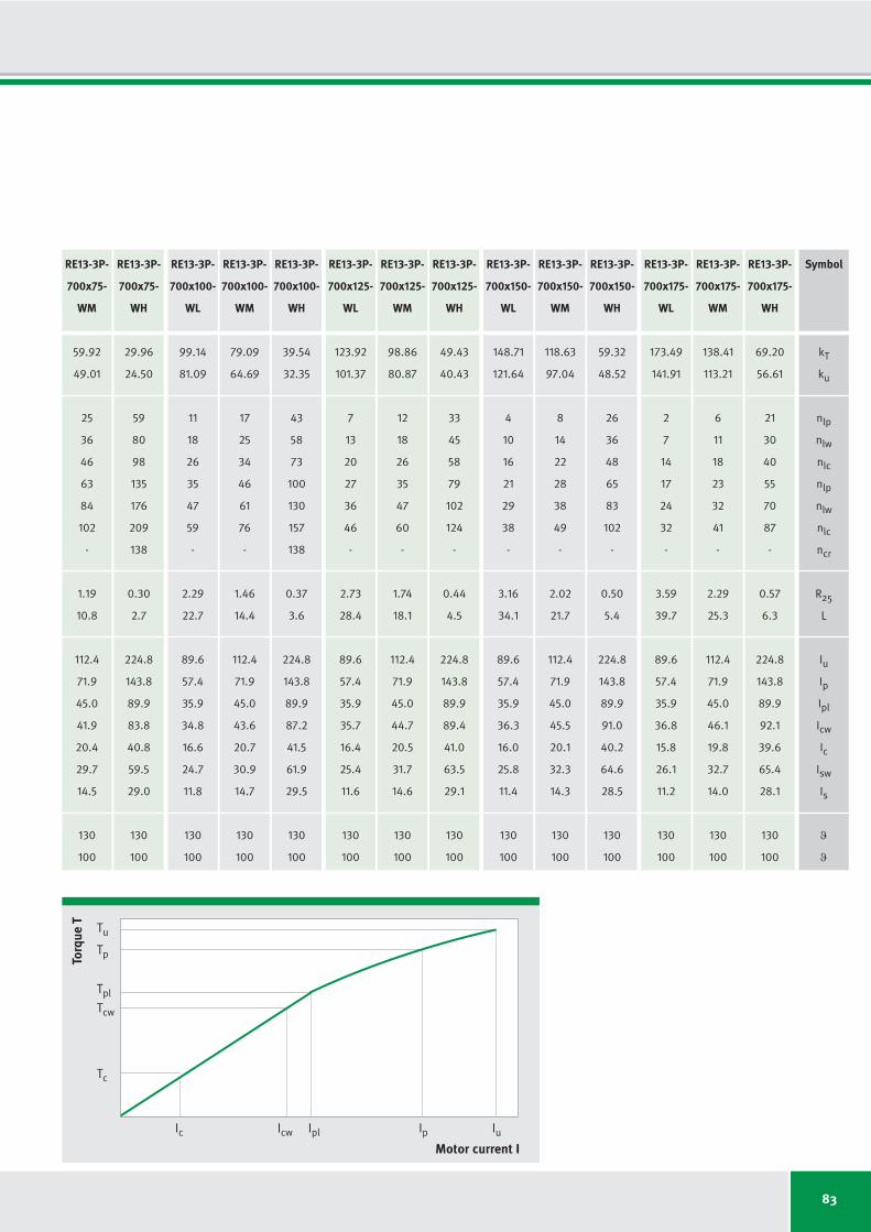
83
99.14
81.09
11
18
26
35
47
59
-
2.29
22.7
89.6
57.4
35.9
34.8
16.6
24.7
11.8
130
100
79.09
64.69
17
25
34
46
61
76
-
1.46
14.4
112.4
71.9
45.0
43.6
20.7
30.9
14.7
130
100
39.54
32.35
43
58
73
100
130
157
138
0.37
3.6
224.8
143.8
89.9
87.2
41.5
61.9
29.5
130
100
123.92
101.37
7
13
20
27
36
46
-
2.73
28.4
89.6
57.4
35.9
35.7
16.4
25.4
11.6
130
100
98.86
80.87
12
18
26
35
47
60
-
1.74
18.1
112.4
71.9
45.0
44.7
20.5
31.7
14.6
130
100
49.43
40.43
33
45
58
79
102
124
-
0.44
4.5
224.8
143.8
89.9
89.4
41.0
63.5
29.1
130
100
148.71
121.64
4
10
16
21
29
38
-
3.16
34.1
89.6
57.4
35.9
36.3
16.0
25.8
11.4
130
100
118.63
97.04
8
14
22
28
38
49
-
2.02
21.7
112.4
71.9
45.0
45.5
20.1
32.3
14.3
130
100
59.32
48.52
26
36
48
65
83
102
-
0.50
5.4
224.8
143.8
89.9
91.0
40.2
64.6
28.5
130
100
173.49
141.91
2
7
14
17
24
32
-
3.59
39.7
89.6
57.4
35.9
36.8
15.8
26.1
11.2
130
100
138.41
113.21
6
11
18
23
32
41
-
2.29
25.3
112.4
71.9
45.0
46.1
19.8
32.7
14.0
130
100
69.20
56.61
21
30
40
55
70
87
-
0.57
6.3
224.8
143.8
89.9
92.1
39.6
65.4
28.1
130
100
RE13-3P-
700x100-
WL
RE13-3P-
700x100-
WM
RE13-3P-
700x100-
WH
RE13-3P-
700x125-
WL
RE13-3P-
700x125-
WM
RE13-3P-
700x125-
WH
RE13-3P-
700x150-
WL
RE13-3P-
700x150-
WM
RE13-3P-
700x150-
WH
RE13-3P-
700x175-
WL
RE13-3P-
700x175-
WM
RE13-3P-
700x175-
WH
Torq
ue T
Motor current I
Tc
Icw IplIc Ip Iu
Tcw
Tpl
Tp
Tu
59.92
49.01
25
36
46
63
84
102
-
1.19
10.8
112.4
71.9
45.0
41.9
20.4
29.7
14.5
130
100
29.96
24.50
59
80
98
135
176
209
138
0.30
2.7
224.8
143.8
89.9
83.8
40.8
59.5
29.0
130
100
RE13-3P-
700x75-
WM
RE13-3P-
700x75-
WH
Symbol
kT
ku
nlp
nlw
nlc
nlp
nlw
nlc
ncr
R25
L
Iu
Ip
Ipl
Icw
Ic
Isw
Is
ϑ
ϑ
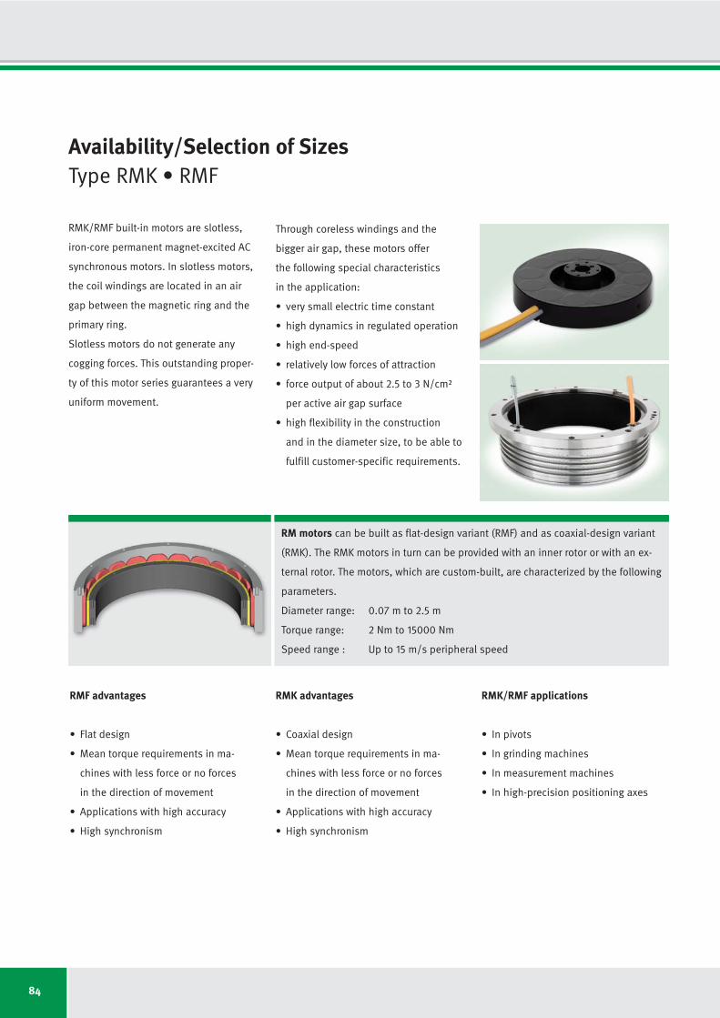
84
Availability/Selection of Sizes Type RMK • RMF
RM motors can be built as flat-design variant (RMF) and as coaxial-design variant
(RMK). The RMK motors in turn can be provided with an inner rotor or with an ex -
ternal rotor. The motors, which are custom-built, are characterized by the following
parameters.
Diameter range: 0.07 m to 2.5 m
Torque range: 2 Nm to 15000 Nm
Speed range : Up to 15 m/s peripheral speed
RMK/RMF built-in motors are slotless,
iron-core permanent magnet-excited AC
synchronous motors. In slotless motors,
the coil windings are located in an air
gap between the magnetic ring and the
primary ring.
Slotless motors do not generate any
cogging forces. This outstanding proper-
ty of this motor series guarantees a very
uniform movement.
Through coreless windings and the
bigger air gap, these motors offer
the following special characteristics
in the application:
• very small electric time constant
• high dynamics in regulated operation
• high end-speed
• relatively low forces of attraction
• force output of about 2.5 to 3 N/cm²
per active air gap surface
• high flexibility in the construction
and in the diameter size, to be able to
fulfill customer-specific requirements.
RMF advantages
• Flat design
• Mean torque requirements in ma-
chines with less force or no forces
in the direction of movement
• Applications with high accuracy
• High synchronism
RMK/RMF applications
• In pivots
• In grinding machines
• In measurement machines
• In high-precision positioning axes
RMK advantages
• Coaxial design
• Mean torque requirements in ma-
chines with less force or no forces
in the direction of movement
• Applications with high accuracy
• High synchronism

85
XXX - XP - DxB - X-X-X-X - XXX
PRIM Primary
SEK Secondary
Model variant
O Without ring (customer provides the ring)
M With ring (ring will be manufactured by IDAM)
K With cooling in the ring (additional outer ring
required)
S Special design
Commutation type
O Without sensors, measurement system commutated
K Sensor commutated, analog, 2x 90° (2P) or
3x 120° (3P)
S Sensor box (C+D), measurement system commutated
E Special design, custom-built
Temperature monitoring
O Standard (KTY84-130 + 2x NC in series | 3x PTC
in series in phases 1, 2, 3 | 1x KTY in phase 2,
if no sensor commutation takes place)
E Extra (special design, according to customer
requirements
Connection variantLD, LD1…LDX Low dynamic
(low electrical energy requirement)
HD, HD1...HDX High dynamic
DimensionsD Average air gap diameter (mm)
B Magnet track width (mm)
Number of motor phases2P 2-phase
3P 3-phase
Motor typeRMF Ring motor, flat windings
RMK Ring motor, windings glued in cylinder jacket
RMD Ring motor flat, winding arrangement double
URM Ring motor flat, magnet arrangement double
DesignationType RMK • RMF
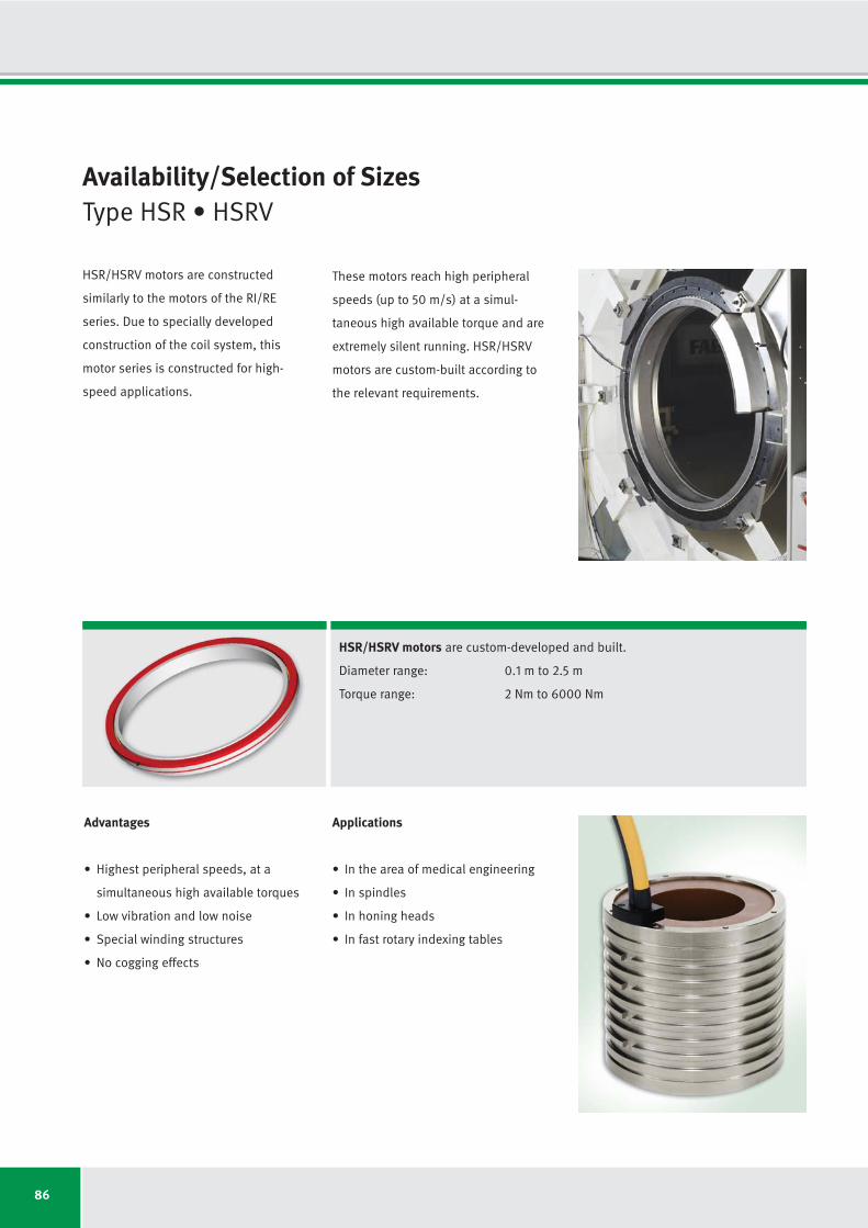
86
HSR/HSRV motors are custom-developed and built.
Diameter range: 0.1 m to 2.5 m
Torque range: 2 Nm to 6000 Nm
Availability/Selection of SizesType HSR • HSRV
HSR/HSRV motors are constructed
similarly to the motors of the RI/RE
series. Due to specially developed
construction of the coil system, this
motor series is constructed for high-
speed applications.
Advantages
• Highest peripheral speeds, at a
simultaneous high available torques
• Low vibration and low noise
• Special winding structures
• No cogging effects
Applications
• In the area of medical engineering
• In spindles
• In honing heads
• In fast rotary indexing tables
These motors reach high peripheral
speeds (up to 50 m/s) at a simul-
taneous high available torque and are
extremely silent running. HSR/HSRV
motors are custom-built according to
the relevant requirements.
87
DesignationType HSR • HSRV
XXXX - 3P - DxH - X-X-X-X - XXX
PRIM Primary
SEK Secondary
Connection variant
LD, LD1…LDX Low dynamic
(low electrical energy requirement)
HD, HD1...HDX High dynamic
Motor type
HSR, HSRV Internal (internal rotor)
HSRE, HSRVE External (external rotor)
Optional additional model code
(e.g. HSRV5)
Model variant
O Housing set (customer provides housing parts)
M Complete motor (parts are made by IDAM)
K With cooling in the ring (additional ring is provided
by IDAM)
Commutation type
O Without sensors, measurement system commutated
S Special design, custom-built
Temperature monitoring
O Standard (KTY84-130 + 2x NC in series | 3x PTC
in series in phases 1, 2, 3 | 1x KTY84 in phase 2
as reserve)
S Special design, custom-built
Dimensions
Effective diameter in the air gap x packet height (mm)
Number of motor phases3P 3-phase

88
Segment Motors
The IDAM built-in motors of all struc tur -
al shapes can also be made custom ized
in segment construction.
In contrast to the continuous rings of
the previously mentioned motors, the
primary and/or the secondary parts are
formed as segments in these motors.
This construction gives particular
advantages in motors with diameters
above 1260 mm or in case of special
geometric requirements.
• Motor segments (primaries) are
easy to manufacture.
• The torque can be scaled via the
number of segments.
• Very big diameters can be realized
economically.
• A redundant construction of torque
motors in segment construction is
thus possible.
• In case of movements less than 180°,
secondary parts can be segmented.
• Very suitable for small drives due to
the reduction of mass.
In combination with HSR magnet
systems, very large segment motors
are suitable for high-speed motors
with large diameters.
This construction has the following
advantages:
• Cost-effective segment construction
• Variation of the number of segments
• Implementation of large motors
• Redundant construction possible
• Reduction of the service costs
• Mass reduction.
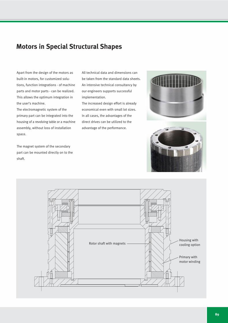
89
Motors in Special Structural Shapes
Apart from the design of the motors as
built-in motors, for customized solu -
tions, function integrations - of machine
parts and motor parts - can be realized.
This allows the optimum integration in
the user’s machine.
The electromagnetic system of the
primary part can be integrated into the
housing of a revolving table or a machine
assembly, without loss of installation
space.
The magnet system of the secondary
part can be mounted directly on to the
shaft.
All technical data and dimensions can
be taken from the standard data sheets.
An intensive technical consultancy by
our engineers supports successful
implementation.
The increased design effort is already
economical even with small lot sizes.
In all cases, the advantages of the
direct drives can be utilized to the
advantage of the performance.
Rotor shaft with magnetsHousing with cooling option
Primary withmotor winding
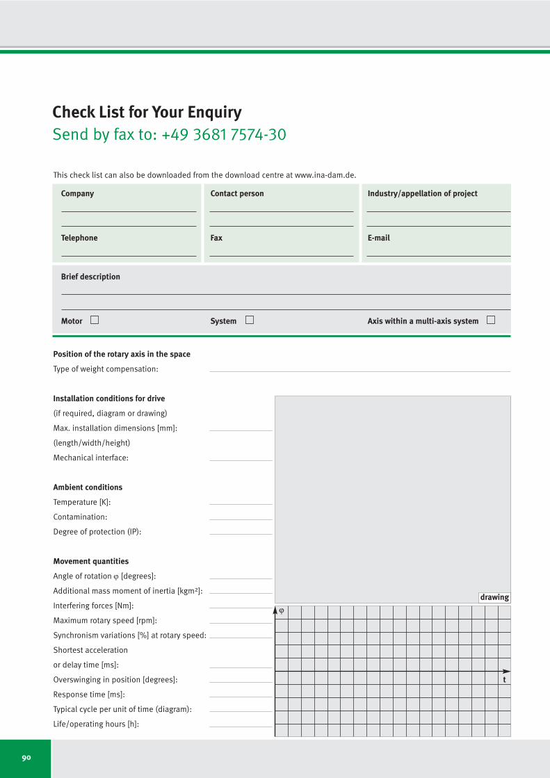
90
Check List for Your EnquirySend by fax to: +49 3681 7574-30
Position of the rotary axis in the space
Type of weight compensation:
Installation conditions for drive
(if required, diagram or drawing)
Max. installation dimensions [mm]:
(length/width/height)
Mechanical interface:
Ambient conditions
Temperature [K]:
Contamination:
Degree of protection (IP):
Movement quantities
Angle of rotation ϕ [degrees]:
Additional mass moment of inertia [kgm2]:
Interfering forces [Nm]:
Maximum rotary speed [rpm]:
Synchronism variations [%] at rotary speed:
Shortest acceleration
or delay time [ms]:
Overswinging in position [degrees]:
Response time [ms]:
Typical cycle per unit of time (diagram):
Life/operating hours [h]:
t
ϕdrawing
This check list can also be downloaded from the download centre at www.ina-dam.de.
Company Contact person Industry/appellation of project
Telephone Fax E-mail
Brief description
Motor System Axis within a multi-axis system
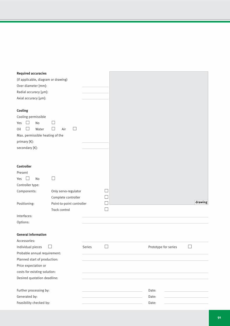
91
Required accuracies
(if applicable, diagram or drawing)
Over diameter [mm]:
Radial accuracy [μm]:
Axial accuracy [μm]:
Cooling
Cooling permissible
Yes No
Oil Water Air
Max. permissible heating of the
primary [K]:
secondary [K]:
Controller
Present
Yes No
Controller type:
Components: Only servo-regulator
Complete controller
Positioning: Point-to-point controller
Track control
Interfaces:
Options:
General information
Accessories:
Individual pieces Series Prototype for series
Probable annual requirement:
Planned start of production:
Price expectation or
costs for existing solution:
Desired quotation deadline:
Further processing by: Date:
Generated by: Date:
Feasibility checked by: Date:
drawing

92
Technical Information and Consulting Services
Class-leading technology and competent
consulting services are two of the major
benefits of working with IDAM.
IDAM application engineers are looking
forward to support you choose the per-
fect drive for your application.
Please contact us:
Phone: +49 3681 7574-0
Industry: Automation/Medical
Technology
E-mail: [email protected]
Industry: Productronics/Measuring
Technology
E-mail: [email protected]
Industry: Production Machinery/Heavy
Industries
E-mail: [email protected]
Industry: Automotive
E-mail: [email protected]
INA/FAG bearings by Schaeffler for the
production machinery
E-mail:
Web:
www.schaeffler.com/machine-tools
TPI 120: High precision
bearings for combined
loads
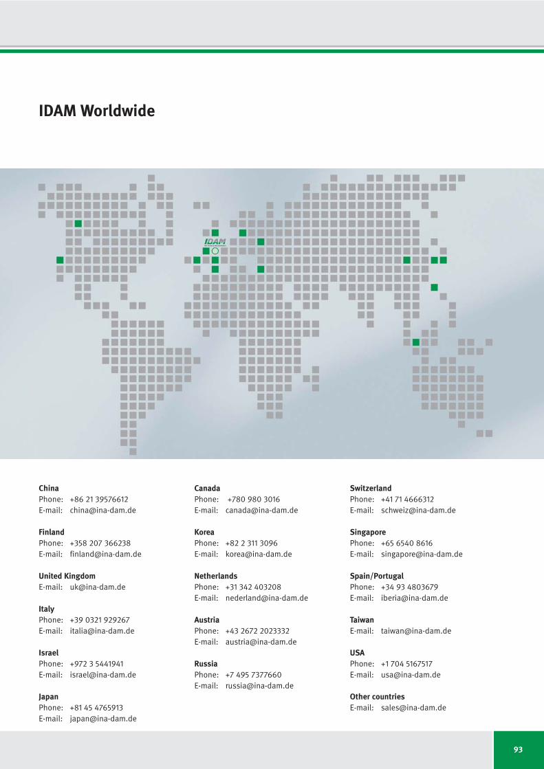
93
IDAM Worldwide
ChinaPhone: +86 21 39576612
E-mail: [email protected]
FinlandPhone: +358 207 366238
E-mail: [email protected]
United KingdomE-mail: [email protected]
ItalyPhone: +39 0321 929267
E-mail: [email protected]
IsraelPhone: +972 3 5441941
E-mail: [email protected]
JapanPhone: +81 45 4765913
E-mail: [email protected]
CanadaPhone: +780 980 3016
E-mail: [email protected]
KoreaPhone: +82 2 311 3096
E-mail: [email protected]
NetherlandsPhone: +31 342 403208
E-mail: [email protected]
AustriaPhone: +43 2672 2023332
E-mail: [email protected]
RussiaPhone: +7 495 7377660
E-mail: [email protected]
SwitzerlandPhone: +41 71 4666312
E-mail: [email protected]
SingaporePhone: +65 6540 8616
E-mail: [email protected]
Spain/PortugalPhone: +34 93 4803679
E-mail: [email protected]
TaiwanE-mail: [email protected]
USAPhone: +1 704 5167517
E-mail: [email protected]
Other countriesE-mail: [email protected]
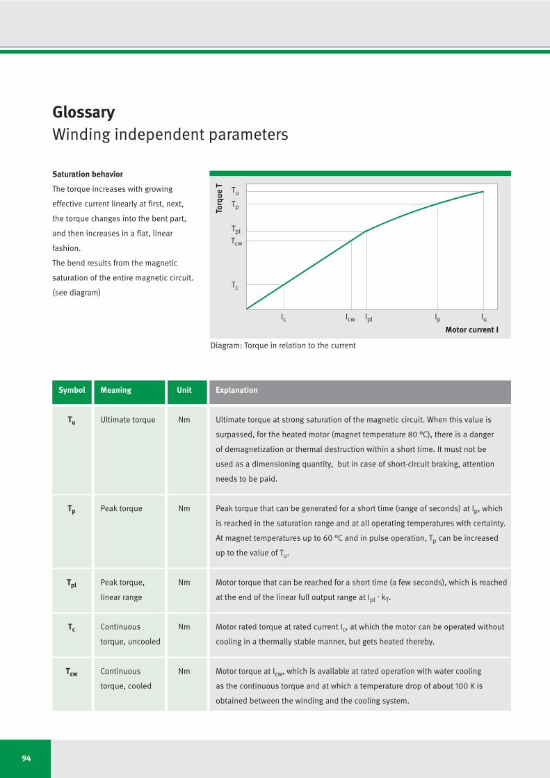
94
Glossary Winding independent parameters
Torq
ue T
Motor current I
Tc
Icw IplIc Ip Iu
Tcw
Tpl
Tp
Tu
Saturation behavior
The torque increases with growing
effective current linearly at first, next,
the torque changes into the bent part,
and then increases in a flat, linear
fashion.
The bend results from the magnetic
saturation of the entire magnetic circuit.
(see diagram)
Diagram: Torque in relation to the current
Symbol Meaning Unit Explanation
Tu Ultimate torque Nm Ultimate torque at strong saturation of the magnetic circuit. When this value is
surpassed, for the heated motor (magnet temperature 80 °C), there is a danger
of demagnetization or thermal destruction within a short time. It must not be
used as a dimensioning quantity, but in case of short-circuit braking, attention
needs to be paid.
Tp Peak torque Nm Peak torque that can be generated for a short time (range of seconds) at Ip, which
is reached in the saturation range and at all operating temperatures with certainty.
At magnet temperatures up to 60 °C and in pulse operation, Tp can be increased
up to the value of Tu.
Tpl Peak torque, Nm Motor torque that can be reached for a short time (a few seconds), which is reached
linear range at the end of the linear full output range at Ipl. kT.
Tc Continuous Nm Motor rated torque at rated current Ic, at which the motor can be operated without
torque, uncooled cooling in a thermally stable manner, but gets heated thereby.
Tcw Continuous Nm Motor torque at Icw, which is available at rated operation with water cooling
torque, cooled as the continuous torque and at which a temperature drop of about 100 K is
obtained between the winding and the cooling system.
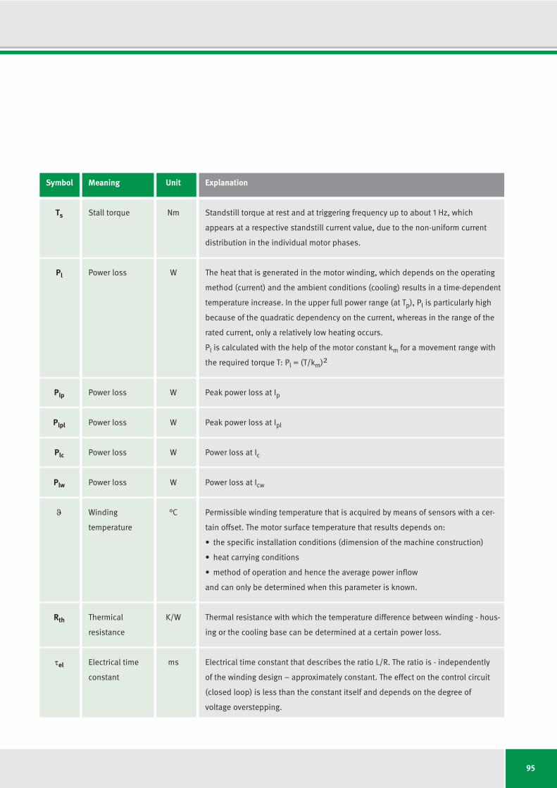
95
Symbol Meaning Unit Explanation
Ts Stall torque Nm Standstill torque at rest and at triggering frequency up to about 1 Hz, which
appears at a respective standstill current value, due to the non-uniform current
distribution in the individual motor phases.
Pl Power loss W The heat that is generated in the motor winding, which depends on the operating
method (current) and the ambient conditions (cooling) results in a time-dependent
temperature increase. In the upper full power range (at Tp), Pl is particularly high
because of the quadratic dependency on the current, whereas in the range of the
rated current, only a relatively low heating occurs.
Pl is calculated with the help of the motor constant km for a movement range with
the required torque T: Pl = (T/km)2
Plp Power loss W Peak power loss at Ip
Plpl Power loss W Peak power loss at Ipl
Plc Power loss W Power loss at Ic
Plw Power loss W Power loss at Icw
ϑ Winding °C Permissible winding temperature that is acquired by means of sensors with a cer-
temperature tain offset. The motor surface temperature that results depends on:
• the specific installation conditions (dimension of the machine construction)
• heat carrying conditions
• method of operation and hence the average power inflow
and can only be determined when this parameter is known.
Rth Thermical K/W Thermal resistance with which the temperature difference between winding - hous-
resistance ing or the cooling base can be determined at a certain power loss.
τel Electrical time ms Electrical time constant that describes the ratio L/R. The ratio is - independently
constant of the winding design – approximately constant. The effect on the control circuit
(closed loop) is less than the constant itself and depends on the degree of
voltage overstepping.
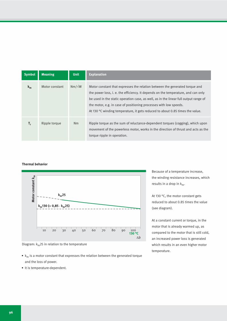
96
Mot
or c
onst
ant k
m
Δϑ
• km is a motor constant that expresses the relation between the generated torque
and the loss of power.
• It is temperature-dependent.
Thermal behavior
Because of a temperature increase,
the winding resistance increases, which
results in a drop in km.
At 130 °C, the motor constant gets
reduced to about 0.85 times the value
(see diagram).
At a constant current or torque, in the
motor that is already warmed up, as
compared to the motor that is still cold,
an increased power loss is generated
which results in an even higher motor
temperature.
10
km130 (≈ 0,85 km25)
20 30 40 50 60 70 80 90 100
.
130 °C
Diagram: km25 in relation to the temperature
Symbol Meaning Unit Explanation
km Motor constant Nm/√W Motor constant that expresses the relation between the generated torque and
the power loss, i. e. the efficiency. It depends on the temperature, and can only
be used in the static operation case, as well, as in the linear full output range of
the motor, e.g. in case of positioning processes with low speeds.
At 130 °C winding temperature, it gets reduced to about 0.85 times the value.
Tr Ripple torque Nm Ripple torque as the sum of reluctance-dependent torques (cogging), which upon
movement of the powerless motor, works in the direction of thrust and acts as the
torque ripple in operation.
km25
97
Glossary Winding dependent parameters
Symbol Meaning Unit Explanation
kT Torque constant Nm/Arms Torque constant, which is in linear full power range multiplied by the current
gives the resultant motor torque: Tc = Ic . kT
ku Back EMF Vs/rad Voltage constant that is obtained in generator operation, and when multiplied
constant by the rotational speed gives the armature counter voltage resulting at the motor
terminals: UEMF = ku. n
nlp Limiting speed rpm Winding dependent limit speed without consideration of the dynamic heat losses
when peak current Ip without field weakening is applied.
After this point the motor torque decreases strongly (see diagram).
nlw Limiting speed rpm Winding dependent limit speed without consideration of the dynamic heat losses
when water cooled continuous current Icw without field weakening is applied.
After this point the motor torque decreases strongly (see diagram).
nlc Limiting speed rpm Winding dependent limit speed without consideration of the dynamic heat losses
when air cooled continuous current Ic without field weakening is applied.
After this point the motor torque decreases strongly (see diagram).
ncr Limiting speed rpm Limit speed under consideration of additional frequency dependent heat losses
(causes by eddy current and cyclic magnetization loss). A continuous, water cooled
operation at limit speed ncr is possible if the applied current is not exceeding
approx. 45% of the water cooled current Icw.
Speed ncr at water cooled current Icw can be operated at a duty-cycle of approx.
20%. In order to reach a duty cycle of 100% at current Icw, a speed reduction to
0.2 x ncr is necessary.
The torque (current) or the duty-cycle at speed ncr can be increased by use of a
special winding variant (Z winding).
UDCL Direct current V Intermediate circuit voltage or supply voltage of the power control elements.
link voltage The higher the speed and the concomitantly rising counter-voltage and frequency-
dependent losses are the higher this voltage must be.
R25
Electrical Ω Winding resistance at 25 °C
resistance At 130 °C, this increases to about 1.4 times the value.
98
Symbol Meaning Unit Explanation
Iu Ultimate current Arms Limiting current at which the magnetic circuit is strongly saturated. It is either
determined by the maximum current density in the winding or through starting
demagnetization danger at a magnet temperature of 80 °C (also see Tu).
Ip Peak current Arms Peak effective current that is in the range of iron saturation and is to be used as a
dimensioning quantity (also see Tp). In case of an only moderately hot rotor
(magnet temperature max. 60 °C) and pulse operation (max. 1 s), Ip can be in-
creased up to the limiting value Iu.
Ipl Peak current, Arms Effective peak current up to which a more or less proportional torque curve occurs.
linear range
Ic Continuous Arms Effective rated current, at which the relevant loss power, depending on the size of
current, uncooled the screw-on base, without forced cooling, results in a relatively small heating up
of the motor.
Icw Continuous Arms Effective rated current that is permissible in case of water cooling in continuous
current, cooled operation.
Is Stall current, Arms Effective standstill current at rest and at control frequencies up to about 1 Hz.
uncooled Due to the different current distribution in the motor phases, for preventing local
overheating, the motor current has to be reduced to this value, if no noticeable
movement takes place beyond a pole pair.
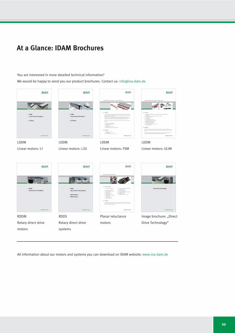
99
At a Glance: IDAM Brochures
LDDM
Linear motors: L1
LDDM
Linear motors: L2U
LDDM
Linear motors: FSM
LDDM
Linear motors: ULIM
RDDM
Rotary direct drive
motors
RDDS
Rotary direct drive
systems
Planar reluctance
motors
Image brochure: „Direct
Drive Technology“
You are interested in more detailed technical information?
We would be happy to send you our product brochures. Contact us: [email protected]
All information about our motors and systems you can download on IDAM website: www.ina-dam.de
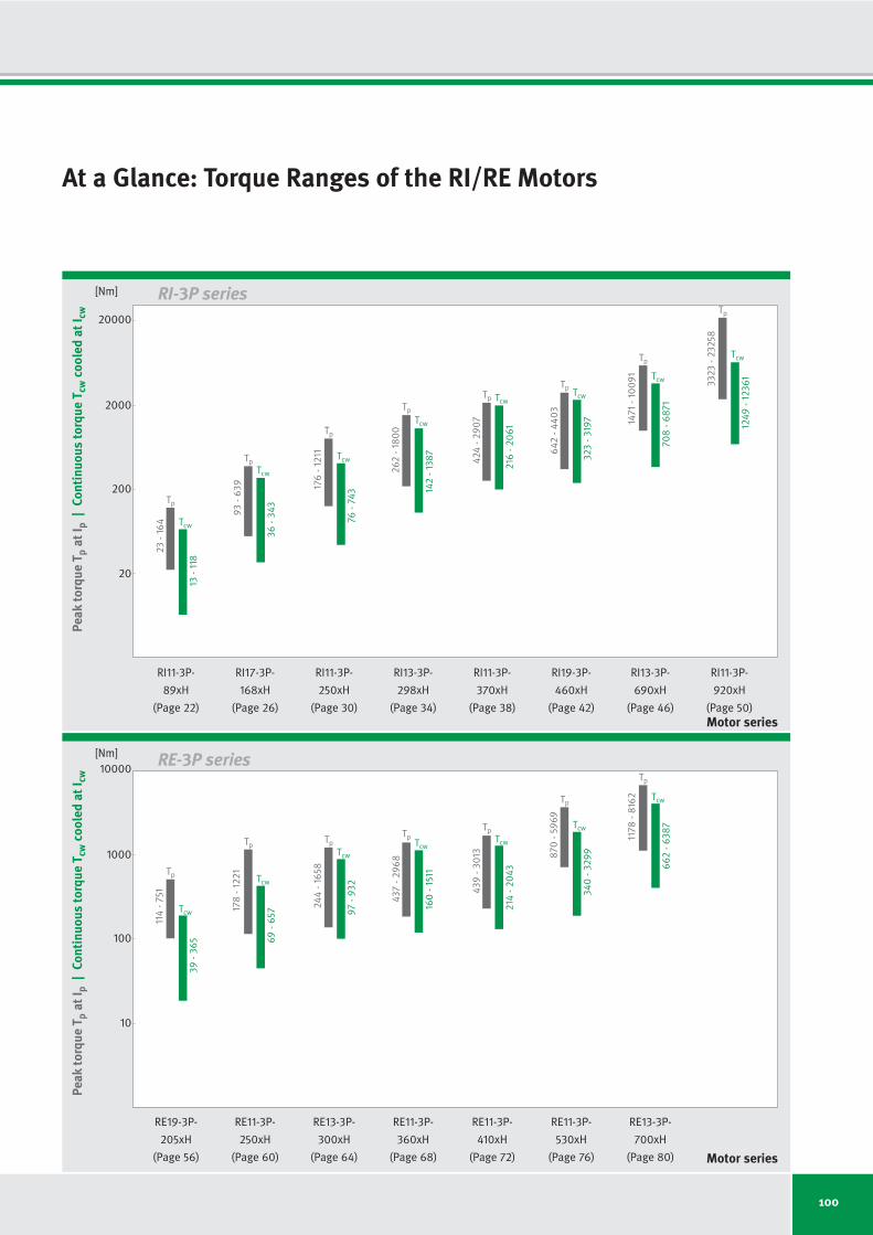
100
At a Glance: Torque Ranges of the RI/RE Motors
RI11-3P- RI17-3P- RI11-3P- RI13-3P- RI11-3P- RI19-3P- RI13-3P- RI11-3P-
89xH 168xH 250xH 298xH 370xH 460xH 690xH 920xH
(Page 22) (Page 26) (Page 30) (Page 34) (Page 38) (Page 42) (Page 46) (Page 50)
20
200
2000
20000
Peak
torq
ue T
pat
I p|
Cont
inuo
us to
rque
Tcw
cool
ed a
t Icw
Motor series
RI-3P series
Tcw
13
- 118
23
- 16
4
36
- 34
3
93
- 6
39
76
- 74
3
17
6- 1
211
14
2- 1
38
7
26
2- 1
80
0
42
4- 2
90
7
64
2- 4
40
3
12
49
- 12
36
1
33
23
- 23
25
8
70
8- 6
87
1
14
71
- 10
09
1
Tp
Tcw
TpTcw
Tp
Tcw
Tp
Tcw
Tp Tcw
216
- 20
61
Tp Tcw
32
3- 3
19
7
Tp
Tcw
Tp
[Nm]
RE19-3P- RE11-3P- RE13-3P- RE11-3P- RE11-3P- RE11-3P- RE13-3P-
205xH 250xH 300xH 360xH 410xH 530xH 700xH
(Page 56) (Page 60) (Page 64) (Page 68) (Page 72) (Page 76) (Page 80)
10
100
1000
10000
Peak
torq
ue T
pat
I p|
Cont
inuo
us to
rque
Tcw
cool
ed a
t Icw
Motor series
RE-3P series
39
- 36
5
114
- 751
69
- 65
717
8- 1
22
1
97
- 93
2
24
4- 1
65
8
16
0- 1
511
43
7- 2
96
8
43
9- 3
013
87
0- 5
96
9
66
2- 6
38
7
117
8- 8
16
2
Tp
Tcw
Tp
Tcw
TpTcw
TpTcw
TpTcw
214
- 20
43
Tp
34
0- 3
29
9
Tp
Tcw
[Nm]
Tcw
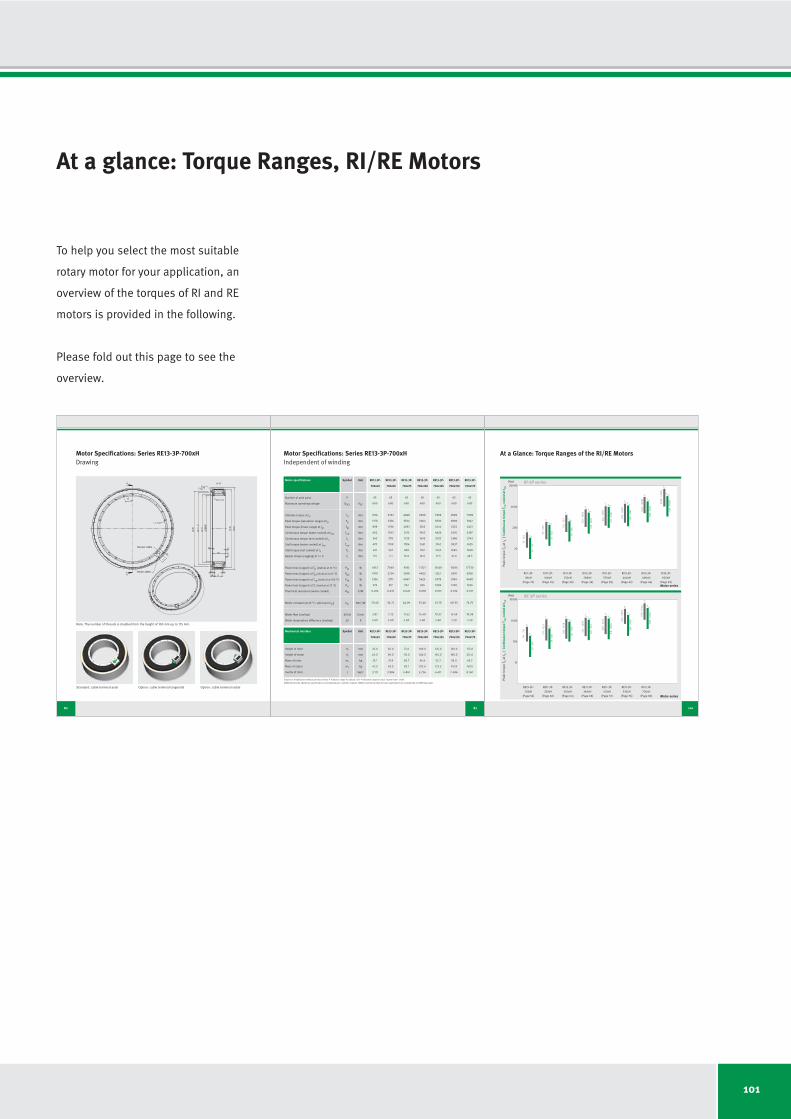
101
At a glance: Torque Ranges, RI/RE Motors
80
Motor Specifications: Series RE13-3P-700xHDrawing
Sensor cable
Motor cable
Standard: cable terminal axial Option: cable terminal tangential Option: cable terminal radial
Note: The number of threads is doubled from the height of 100 mm up to 175 mm.
81
Motor specifications Symbol Unit RE13-3P- RE13-3P- RE13-3P- RE13-3P- RE13-3P- RE13-3P- RE13-3P-
700x25 700x50 700x75 700x100 700x125 700x150 700x175
Number of pole pairs P
Maximum operating voltage UDCL VDC
Ultimate torque at Iu Tu Nm
Peak torque (saturation range) at Ip Tp Nm
Peak torque (linear range) at Ipl Tpl Nm
Continuous torque (water cooled) at Icw Tcw Nm
Continuous torque (not cooled) at Ic Tc Nm
Stall torque (water cooled) at Isw Tsw Nm
Stall torque (not cooled) at Is Ts Nm
Ripple torque (cogging) at I = 0 Tr Nm
Power loss (copper) at Tp (statical at 25 °C) Plp W
Power loss (copper) at Tpl (statical at 25 °C) Plpl W
Power loss (copper) at Tcw (statical at 100 °C) Plw W
Power loss (copper) at Tc (statical at 25 °C) Plc W
Thermical resistance (water cooled) Rth K/W
Motor constant (at 25 °C; valid up to Ipl) km Nm/√W
Water flow (cooling) dV/dt l/min
Water temperature difference (cooling) Δϑ K
Mechanical interface Symbol Unit RE13-3P- RE13-3P- RE13-3P- RE13-3P- RE13-3P- RE13-3P- RE13-3P-
700x25 700x50 700x75 700x100 700x125 700x150 700x175
Height of rotor H1
mm
Height of stator H2
mm
Mass of rotor m1
kg
Mass of stator m2
kg
Inertia of rotor J kgm2
65
600
1616
1178
898
662
340
470
241
3.5
4913
1919
1356
275
0.074
20.49
3.87
5.00
25.0
65.0
25.1
42.5
3.111
50.0
90.0
31.9
62.5
3.986
75.0
115.0
38.7
82.1
4.861
100.0
140.0
45.4
102.6
5.736
125.0
165.0
52.2
122.3
6.611
150.0
190.0
59.0
141.9
7.486
175.0
215.0
65.7
161.5
8.361
65
600
3232
2356
1796
1563
778
1109
552
7.1
7049
2754
2711
517
0.037
34.22
7.75
5.00
65
600
4848
3534
2693
2515
1225
1786
869
10.6
9185
3588
4067
742
0.025
44.96
11.62
5.00
65
600
6399
4664
3555
3453
1643
2451
1167
14.0
11321
4422
5423
945
0.018
53.46
15.49
5.00
65
600
7999
5830
4444
4426
2032
3142
1443
17.5
13458
5257
6778
1099
0.015
61.29
19.37
5.00
65
600
9599
6996
5333
5405
2386
3837
1694
21.0
15594
6091
8134
1220
0.012
68.33
15.49
7.50
65
600
11199
8162
6221
6387
2743
4535
1948
24.5
17730
6926
9490
1346
0.011
74.76
18.08
7.50
Motor Specifications: Series RE13-3P-700xHIndependent of winding
Subject to modification without previous notice. • Tolerance range for values: ±5% • Tolerance range for value “power loss”: ±10%
IDAM will provide additional specifications and drawings per customer request. IDAM recommends that all motor applications be reviewed by an IDAM specialist.
At a Glance: Torque Ranges of the RI/RE Motors
RI11-3P- RI17-3P- RI11-3P- RI13-3P- RI11-3P- RI19-3P- RI13-3P- RI19-3P-
89xH 168xH 250xH 298xH 370xH 460xH 690xH 920xH
(Page 22) (Page 26) (Page 30) (Page 34) (Page 38) (Page 42) (Page 46) (Page 50)
20
200
2000
20000
Peak
torq
ue T
pat
I p|
Cont
inuo
us to
rque
Tcw
cool
ed a
t Icw
Motor series
RI-3P series
Tcw
13
- 118
23
- 16
4
37
- 34
5
93
- 6
39
78
- 74
6
17
6- 1
211
14
3- 1
38
7
26
2- 1
80
0
42
4- 2
90
7
64
2- 4
40
3
12
11
- 119
18
259
8- 1
78
20
70
8- 6
87
1
14
71
- 10
09
1
Tp
Tcw
TpTcw
Tp
Tcw
Tp
Tcw
Tp Tcw
216
- 20
61
Tp Tcw
33
0- 3
19
7
Tp
Tcw
Tp
[Nm]
RE19-3P- RE11-3P- RE13-3P- RE11-3P- RE11-3P- RE11-3P- RI13-3P-
205xH 250xH 300xH 360xH 410xH 530xH 700xH
(Page 56) (Page 60) (Page 64) (Page 68) (Page 72) (Page 76) (Page 80)
10
100
1000
10000
Peak
torq
ue T
pat
I p|
Cont
inuo
us to
rque
Tcw
cool
ed a
t Icw
Motor series
RE-3P series
39
- 36
5
114
- 751
70
- 66
117
8- 1
22
1
10
1- 9
44
24
4- 1
65
8
16
0- 1
511
43
7- 2
96
8
43
9- 3
013
87
0- 5
96
9
69
3- 6
46
6
117
8- 8
16
2
Tp
Tcw
Tp
Tcw
TpTcw
TpTcw
TpTcw
219
- 20
56
Tp
35
5- 3
33
9
Tp
Tcw
[Nm]
Tcw
100
To help you select the most suitable
rotary motor for your application, an
overview of the torques of RI and RE
motors is provided in the following.
Please fold out this page to see the
overview.
Issue: May 2010 I Subject to modification without previous notice. I Photos: IDAM GmbH & Co. oHG
INA - Drives & Mechatronics GmbH & Co. oHG
Mittelbergstrasse 2
98527 Suhl I Germany
Phone +49 3681 I 7574-0
Fax +49 3681 I 7574-30
E-mail [email protected]
Web www.ina-dam.de