rck mustang manual - total control products
TRANSCRIPT
SAFETY PRECAUTIONSPARTS LIST
INSTALLATIONADJUSTMENT
CARE AND MAINTENANCE
READ AND SAVETHESE INSTRUCTIONS
OWNERSMANUAL
FOR1964 - 1970MUSTANG
RACK&
PINIONCONVERSION
KITMANUAL
&POWER
READ AND FOLLOWALL
SAFETY RULES,INSTRUCTIONS AND
WARRANTYDISCLAIMER
BEFOREINSTALLATION.
CAUTION
TM MANUAL RACK AND PINION
POWER RACK AND PINION
WARNING!!!DO NOT USE SYNTHETIC POWER STEERING FLUIDOR ATF WITH THE POWER RACK AND PINION UNIT.DOING SO MAY DAMAGE THE SEALS WITHIN THE
RACK TUBE.
READ THIS MANUAL IN ITS ENTIRETY PRIOR TOBEGINING INSTALLATION.
Revision 08/10/20047903-RCKMP-00
OWNER�S INFORMATION
OUR PLEDGE TO ASSIST YOUOur Technical Support Department can be contacted by email or through our online discussion forum foradditional help and tips if needed.
Email: [email protected] Forum: www.totalcontrolproducts.com/support.html
Additional products and replacement components are available through our sales office during regular businesshours.
2
Our products are manufactured to the highest quality standards. To ensure your complete satisfaction, pleasefollow these simple steps:
Read the entire Owners Manual before you begin installation. The Owners Manual included with yourproducts has been designed to make the installation of your products easy and trouble free.
Returns:Merchandise can only be returned within 30 days of the original shipping date. No returns on special order itemsor shipping and handling fees. Returns will only be accepted on parts that have not been installed or modified;are still in the original package; and are in like-new condition. A 25-percent restocking fee will be applied to allreturned merchandise. If upon examination all parts are returned complete and in like-new condition, a credit willbe issued less the 25-percent restocking fee. Credit can be applied toward any products offered through theTotal Control Products or Chassisworks product catalogs, advertisements or websites. Before returning a part,you must contact Chassisworks to receive a "Return Authorization Number" (RA#), which must be clearlyvisible on the outside of the box. All shipping charges on return packages must be prepaid. C.O.D. shipmentswill not be accepted.
Warranty & Liability NoticeThere are NO WARRANTIES, either expressed or implied. Neither the seller nor manufacturer will be liable forany loss, damage or injury, either direct or indirect, arising from the use or inability to determine the appropriateuse of any product. Before any attempt at installation, all drawings and/or instruction sheets should be com-pletely reviewed to determine the suitability of the product for its intended use. In this connection, the userassumes all responsibility and risk. We reserve the right to change specification without notice. Further, ChrisAlston�s Chassisworks, Inc., makes NO GUARANTEE in reference to any specific class legality of any compo-nent. MOST PRODUCTS ARE INTENDED FOR RACING AND OFF-ROAD USE AND MAY NOT BE LEGALLYUSED ON THE HIGHWAY. The products offered for sale are true race-car components and, in all cases,require some fabrication skill to install.
NO PRODUCT OR SERVICE IS DESIGNED OR INTENDED TO PREVENT INJURY OR DEATH.
Total Control ProductsA Chris Alston�s Chassisworks, Inc. Brand8661 Younger Creek DriveSacramento, CA 95828www.totalcontrolproducts.com
Monday - Friday from 7:00 am to 5:30 pm PST.Phone: 916-388-0288Website: www.totalcontrolproducts.com

INTRODUCTIONYou can update your classic automobile to Rack & Pinion steering. Our kits have no effect on caster/camber alignment or brake systems. If you have alignment , suspension or brake problems after installa-tion of the rack and pinion kit, the conditions were probably existing prior to the installation. Inspect yourcars suspension system prior to installation of the rack and pinion kit. We recommend taking your car toa reliable alignment shop to adjust the settings.
Parts list and general maintenance information are available on page 9.
3
1) ELECTRICAL - Remove the battery cable from the negative side of the battery.
2) RAISE VEHICLE -2a) On 64-early 67 Mustangs with non-collapsible steering shafts, you must raise the car to a
level high enough to remove the steering box from underneath.2b) On Late 67-70 Mustangs it will be necessary to raise the car high enough to work comfortably
underneath it prior to removing the factory steering system.
THINK SAFETY FIRST!!!!! ALWAYS USE CAUTION WHEN LIFTING THE CAR
WARNING!!! Always use approved automotive jack stands. All work must be performed on a concretefloor with the jack stands underneath the framerails of the car. Floor jacks must only be used to raise thecar. Never depend on a floor jack to support the car!!!
3) REMOVAL OF FACTORY COMPONENTS - Refer to diagrams on pages 12 & 13.Remove tubular crossmember that is bolted between the frame rails. Two large bolts should beremoved to take out the crossmember. This will be the mounting location for the rack.
3a) Power steering cars converting KRC Power Steering PumpDisconnect the two power steering lines between the power steering pump and the controlvalve at the valve end of the lines. Loosen fastening bolts to power steering pump andswing pump down to remove tension on the fan belt. Remove fan belt. Remove all powersteering pump brackets. You should now be able to remove the pump, brackets andhoses as one complete assembly. Use a suitable container to drain the fluid and disposeof in an environmentally safe manner.
3b) Steering Linkage -Remove inner tie rod from center link using pickle fork or similar tool. Remove the centerlink from the pitman arm using a pickle fork or similar tool. Unbolt ram bracket from frame(factory power steering only). Unbolt idler arm from car. Remove the system from the car.
INSTALLATION INSTRUCTIONS

4
#1. Steering wheel to column clearance (1/16� to 3/32�).If your steering wheel is too far or too close to the steering column tube, you have two options. If the steering wheel touches column, you must cutan appropriate length from end of column tube to allow clearance. If your steering wheel is too far from tube, 3/4� inside diameter shims or washerscan be placed between the retaining clip and roller bearing. Torque steering wheel attaching nut to 50 ft. lbs.
Foot Notes:
4) STEERING COLUMN REMOVAL -4a) 64-Early 67 (non-collapsible shaft) - Remove the steering wheel nut and steering wheel.
Disconnect turn signal harness from under the dash. Unbolt the firewall seal assembly.Remove steering column bracket from under the dash. Remove the column from the car.Make sure to save the upper steering shaft bearing and spring. You must retain the factoryseal, however discard the factory seal retainer.
4b) Late 67-70 (collapsible shaft) - Unbolt the rag joint from the steering box. Unbolt columnsupport and seal assembly from inner fire wall. Disconnect the turn signal harness fromunder the dash. Remove the underdash support bracket. Remove the column from thecar.
5) STEERING BOX REMOVAL - Locate the three bolts that run through the driver�s side of the carframe into the steering box housing. Remove all three.
5a) 64-Early 67 (non-collapsible shaft) - The steering box can be lowered under thecar for removal at this time. If your car is a 1965 V8 with original style motor mounts, it maybe necessary to un-bolt the motor mounts and raise the engine. 1965 V8 original stylemotor mounts place the engine in a higher position then the updated 66-67 style mountsand interfere with the removal of the steering box.
5b) Late 67-70 (collapsible shaft) - Remove steering box from car.
6) STEERING COLUMN PREPARATION 65-EARLY 67 (long shaft) -6a) With the column out of the car place the steering column tube into a vice and carefully cut off
the tube with a hack saw or similar tool. Overall length should be 29 5/16� after cutting. Becareful to cut this tube straight, this end of thesteering tube will rest against the bearingretainer assembly. Carefully debur the end ofthe tube.
6b) Slide column floor mount assembly onto column tube with the two bent tabs pointing towardsthe top of the column. Install supplied steering shaft and bearing retainer assembly onto the bottom endof the steering column tube, make sure that the retainer bottoms against the column tube. Install theupper column bearing and spring. Install steering wheel and steering wheel nut. Temporarily tightensteering wheel nut. (see foot note #1) Use a 9/64� or .140� diameter drill bit and drill holes into the col-umn through the bearing retainer. Remove steering wheel nut, steering wheel, steering shaft and bearingassembly to remove the metal chips from the inside of the column tube. Re-install the steering shaftand bearing retainer assembly, install the upper column bearing and spring, temporarily install the steer-ing wheel and nut, tighten to 10 ft-lbs. The steering wheel will need to be indexed after the car is on theground and has been driven, this will be done in step #14. Install three stainless steel Phillips sheet metalscrews to attach the bearing retainer to the column tube.

5
7) STEERING COLUMN PREPARATION LATE 67-70 (collapsible shaft) -7a) Remove the slipshaft from the end of the steering column. Remove the plastic sleeve from the
bottom of the steering column and tap the inner sleeve of the steering column flush with theouter column tube.
7b) Install the supplied slip shaft and bearing retainer assembly onto column making sure thatthe new female slip shaft engages with the internal male shaft. You may have to tap thenew slip shaft onto the internal shaft until the blue bearing retainer is bottomed against thesteering column. Use a 9/64� or .140 diameter drill bit and drill holes into the columnthrough the bearing retainer. Remove the bearing retainer assembly and steering shaft toremove the metal chips from the inside of the steering column. Re-install the steering shaftand bearing retainer assembly. Install the three stainless steel Phillips sheet metal screwsto attach the bearing retainer assembly to the steering column.
8) STEERING COLUMN INSTALLATION -8a) 64-EARLY 67 (non-collapsible shaft) - Install factory firewall seal over the end of the
assembled steering column. Re-install the column assembly through the hole in the firewall.Adjust the steering column to its original height and reinstall the upper dash bracket. Attachthe column floor mount support assembly and factory firewall seal using original sheetmetal screws from the factory plate. Re-connect the turn signal harness.
8b) LATE 67-70 (collapsible shaft) - Slide the column assembly through the hole in the firewall.Adjust the steering column to its original height and install the upper dash bracket.Reattach the factory lower column support and seal assembly using the original screws.Reconnect the turn signal harness.
9) RACK AND PINION INSTALLATION - Remove the two inner control arm brackets and thepassenger side outer bracket from the rack and pinion by removing the two 5/16� Allenhead bolts in each clamp.
9a) 1964 - 1966 - Bolt inner brackets to the lower control arm mounting points using the 1/2� x 4-1/2� bolts, 1/2� flat washers and 1/2� nylock nuts. It may be necessary to use the suppliedround 1/4� thick spacers in between the brackets and the body to align the brackets withthe rack and pinion tube. The mounting tabs on the inner brackets should point outward.Do not tighten the bolts at this time, the brackets must be able to move.
9b) 1967 - 1970 - You must eliminate the stock eccentric bolts using the supplied eccentriceliminator plates (TCP EE-02) these plates allow the camber to be adjusted to 11 differentpositions. Use 2 plates per side of the vehicle. Bolt inner control arm brackets to lowercontrol arm mounting points using the 1/2� x 4-1/2� bolts, 1/2� flat washers, eccentric platesand 1/2� nylock nuts. The mounting tabs of the inner brackets must point inward. Do nottighten the bolts at this time, the brackets must be able to move.
9c) Mount passenger side outer bracket to frame using the supplied 1/2� bolt, 1/2� lock washerand 1/2� flat washer. Do not tighten at this time.

6
9d) With assistance install the rack and pinion unit into the passenger side frame clamp usingone clamp and two 5/16� Allen bolts. Do not tighten at this time. You may need to use theslotted 1/4� thick square spacers to space the outer rack brackets away from the framerails to provide clearance for the oil pan.
9e) The supplied intermediate shaft will need to becut to fit between the two universal joints asshown in the illustration. Estimated lengths arelisted below. You will need to measure todetermine the correct length for yourapplication.
Manual Big Block - 10�Manual Small Block - 9�Power Big Block - 6-1/8�Power Small Block - 5-1/8�
Install the intermediate shaft assembly onto the end of the steering column shaft. Tightenthe U-joint set screw using a 5/32� Allen wrench, torque to 15-17 ft-lbs. Tighten the U-jointset screw nut to 15-17 ft-lbs. Raise the left end of the rack and install the second U-joint onthe splined end of the rack and pinion input shaft.
Once the spline is engaged the left side of the rack and pinion can now be bolted to theframe using the 1/2� bolt, lock washer, and flat washer. If you used a 1/4� spacer in step9d you will need to use the second spacer between the driver side frame bracket and theframe. It may be necessary to slide the steering column up or down to insure that theintermediate steering shaft clears the clutch linkage, frame, etc.
9f) Install clamps to inner brackets using 5/16� Allen bolts. Now all brackets can be tightened,torque all bolts in an even manner - similar to torquing a head gasket. This should bedone in four stages to insure that everything stays in alignment. Tighten all U-joint setscrews and nuts.
10a) 1964 - 1966 (TCP TIER-01)Slide tie-rod adapters on the inner tie-rod ends and insert through the outerholes on the center link. Use the 7/16� flat washers under the castle nuts and torque to35ft-lbs. Line up cotter pin hole and insert cotter pin. Wrap the ends of the pin around thenut to insure that the cotter pin does not make contact with the rubber boots or rackhousing. Install the centerlink to the rack and pinion assembly using the provided flatwashers and the nylock nuts. Torque the nuts to 75 ft-lbs.
10) CONNECTING TIE-ROD ENDS TO THE CENTERLINKRemove the center link from the rack and pinion.Before connecting the Tie-rod assembilies to thecenter link make sure that they are similar in length oneach side of the car before bolting them to thecenterlink. The tie-rod sleeve clamps must be facingthe rear of the car to provide maximum clearancebetween the tie-rods and the rack.
(Be careful to not let the intermediate shaftinterfere with the operation of the U-joint.)

7
10c) 1969 BOSS and 1970 (TCP TIER-03)Slide tie-rod adapters on the inner tie-rod ends and insert through the inner holes on thecenter link. Big Block cars will use the hole located on the raised tab. Use the 1/2� flatwashers under the castle nuts and torque to 35ft-lbs. Line up cotter pin hole and insertcotter pin. Wrap the ends of the pin around the nut to insure that the cotter pin does notmake contact with the rubber boots or rack housing. Install the centerlink to the rack andpinion assembly using the provided flat washers and the nylock nuts.Torque the nuts to 75 ft-lbs.
11) TIGHTENING STEERING COLUMN - Tighten all steering column bolts under the dash and at thefirewall.
12) FINAL INSPECTION - As a precautionary measure, it is critical that you re-check all work to makesure that all bolts are properly torqued and that there is no interference with any moving parts. Ifyou are driving your car to the alignment shop you should now set the toe-in as close as possiblewith a tape measure.
13) RECONNECTING THE BATTERY CABLE - Reconnect the negative battery cable.
14) PRE-ALIGNMENT SETTINGS FOR THE RACK&PINION - On the passenger side tie-rod sleeve,make sure that the sleeve clamps are facing the rear of the car to clear the end of the rack tube atfull right-hand lock. The steering wheel should now be indexed and the steering wheel nut shouldbe torqued to 50 ft-lbs.
NOTE: When the car is aligned make sure that the rack is centered and the tie-rod assembliesare close to the same length on each side of the car before proceeding with the alignment.
Refer to page 9 for recommended alignment settings.
10b) 1967 - 1969 excluding BOSS (TCP TIER-02)Slide tie-rod adapters on the inner tie-rodends and insert through the inner holes on thecenter link. Big Block cars will use the holelocated on the raised tab. Use the 7/16� flatwashers under the castle nuts and torque to35ft-lbs. Line up cotter pin hole and insertcotter pin. Wrap the ends of the pin aroundthe nut to insure that the cotter pin does not make contact with the rubber boots or rackhousing. Install the centerlink to the rack and pinion assembly using the provided flatwashers and the nylock nuts. Torque the nuts to 75 ft-lbs.

8
POWER STEERING INSTALLATION INSTRUCTIONS
Installation of the power rack and pinion requires the hydraulic hoses to be routed and hooked up to theTCP KRC power steering pump and remote reservoir. Instructions for mounting the pump and assemblyof the hoses are provided in their respective kits.
Before proceeding the following steps must be completed.� Resevoir securely mounted in area of power steering pump� Pump securely mounted and aligned with an available pulley
1) With one hose end installed, hook the hose end to its appropriate fitting.
2) Route the hose as you intend to for the final installation.When installing and routing the hydraulic hoses it is critical to keep them away from all heatsources and sharp edges. Every car will be a little different depending on engine size, header ormanifold configuration, etc. If routing close to the exhaust is unavoidable, it may be necessary touse protective hose wrapping available from Earls, Aeroquip or Parker.
Pump to Rack: -6 (smaller) hoseRack to Reservoir: -6 (smaller) hoseResevoir: to Pump: -10 (larger) hose
3) Mark the hose for the desired length then remove for cutting and assembly of the second hose end asoutlined in the hose kit instructions. Hoses should not be routed and secured in a way that placestight bends in the hose or does not allow any flexibility. Large sweeping bends and some slack toallow engine movement and hydraulic pressure changes is mandatory for optimum performance.
4) Throughly clean the inside of hoses as described in the hose kit instructions to prevent debris fromcontaminating the pump or rack and pinion.
5) Reinstall finished hoses and secure or wrap as necessary.
6) INITIAL STARTUP - When filling the power steering pump it is critical to use a petroleumbased(NON-SYNTHETIC) power steering fluid. It will normally take 1 to 1.5 quarts of fluid to fill thesystem.
6a) Fill the reservoir6b) Start the car with the wheels off the ground6c) Rotate the steering wheel lock to lock 3 to 4 times to purge the air from the system. Be sure
to keep the reservoir topped off during this process. Upon initial startup there may besome noise caused by air. Most systems will need to set overnight to allow small airbubbles to work themselves out.
n Do not use synthetic power steering fluid of ATF with the TCP Rack and Pinion unit.
n The TCP Rack and Pinion has been matched to the flow characteristics of the KRCpower steering pump. Any substitutions of equipment will give unpredictable results.

APPENDIX ARACK AND PINION PARTS LIST
9
PINION ADJUSTMENT
Because of the mechanical nature of a rack and pinion system there is an initial �break-in� period and itwill show signs of wear after years of frequent use. A gear adjustment feature is designed into the rack tomake adjustments to keep the steering as precise as new.
The large jam nut at the back of the pinion housing will need to be loosened to adjust the set screw in thecenter. Adjustment are made in roughly 1/16 of a turn increments or just a few degrees. Tightening this setscrew removes play and loosening will free up movement of the rack gear. Hold the set screw in positionas the jam nut is tightened to prevent it from changing the intended adjustment setting.
RACK AND PINION TORQUE SPECIFICATIONSThread Dia. Torque Value
1) Outer frame brackets to frame 1/2-13 75 ft-lbs2) Lower control arm brackets 1/2-13 75 ft-lbs3) Inner bracket clamp bolts 5/16-24 13-15 ft-lbs4) RH outer bracket clamp bolts 5/16-24 13-15 ft-lbs5) U-joint set screw and nut 5/16-24 15-17 ft lbs6) Centerlink to R&P unit 1/2-13 75 ft-lbs7) Steering wheel nut 5/8-18 50 ft-lbs
RECOMMENDED ALIGNMENT SETTINGSApplication Camber Caster ToeStreet 0 - 1/2 degree neg. 2 1/2 - 3 pos. 1/16� - 1/8� InTrack 1 - 2 degree neg. 2 1/2 - 3 pos. 1/32� - 1/8� In
xiferPtraP noitpircseD ytQXX-XKCR teSnoiniPdnakcaR
stekcarBhtiwylbmessAnoiniPdnakcaR 1gaBerawdraH 1
XX-MLOC teSnmuloCtfahSnmuloC 1
ylbmessAreniateRgniraeBnmuloC 1)elbacilppafi(tnuoMroolF 1
gaBerawdraH 1XX-TFSI teStfahSetaidemretnI
knalBtfahSgnireetSetaidemretnI 1)denilps-non(tnioJlasrevinUreppU 1
)denilps(tnioJlasrevinUrewoL 1XX-REIT teSdoReiT
sretpadAdoReiT 2gaBerawdraH 1
XX-EE teSrotanimilEcirtneccE)elbacilppafi(setalPcirtneccE 4
)elbacilppafi(srecapStnuoMkcaR 2
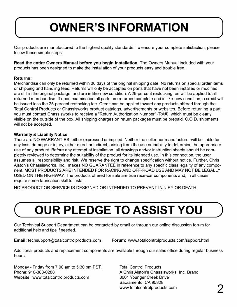
65-66 MANUAL RACK & PINION
67-70 MANUAL RACK & PINION
i j g
v
b
ac
hk
f f
a
e
e
fg
h
i j
k
f
w
Tapered Adapters
Tapered Adapters
d
10
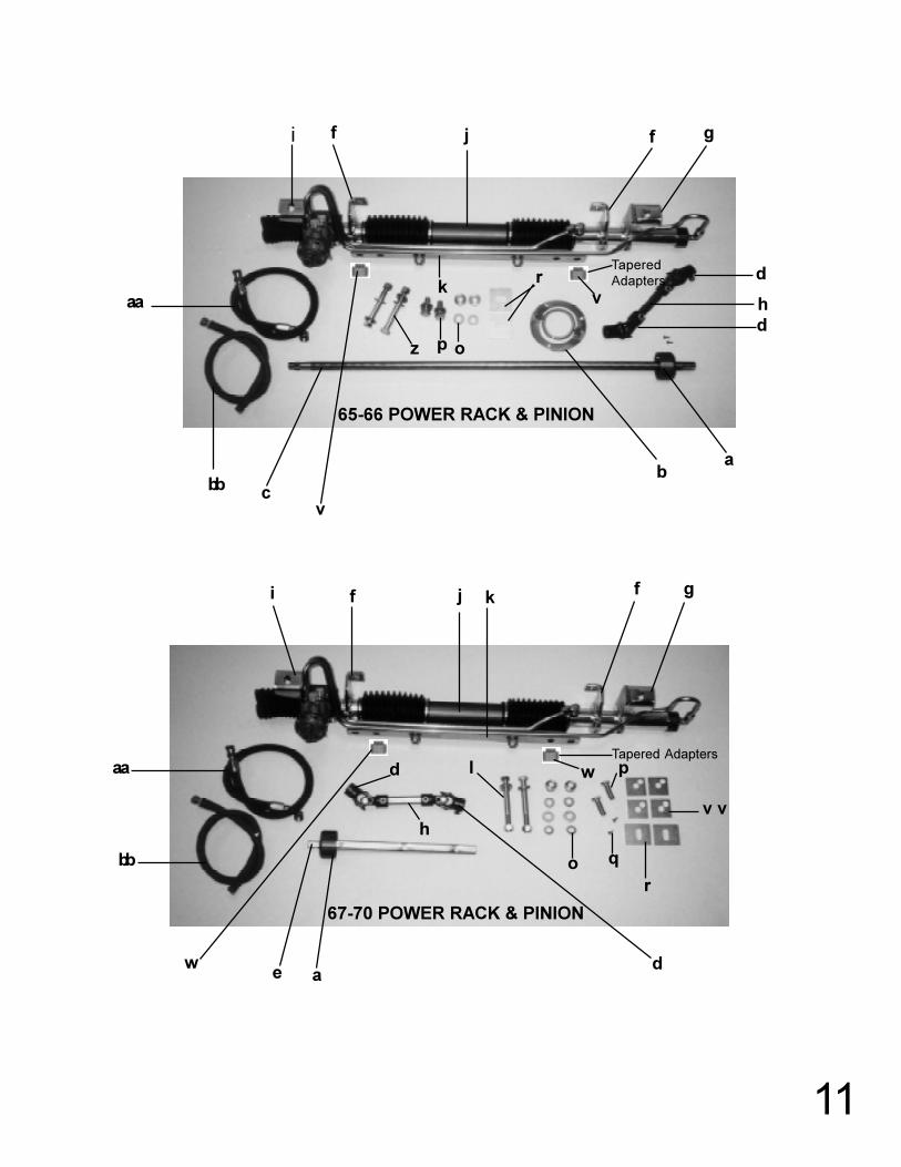
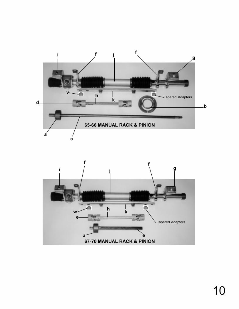
65-66 POWER RACK & PINION
67-70 POWER RACK & PINION
TaperedAdapters
Tapered Adapters
i f j f g
aa
bb cv
ba
d
hk r
v
pz od
i f j k f g
w
bb
aa
e ad
l
o
p
q
r
w
v v
d
h
11

FACTORY POWER SYSTEM
FACTORY MANUAL SYSTEM
12
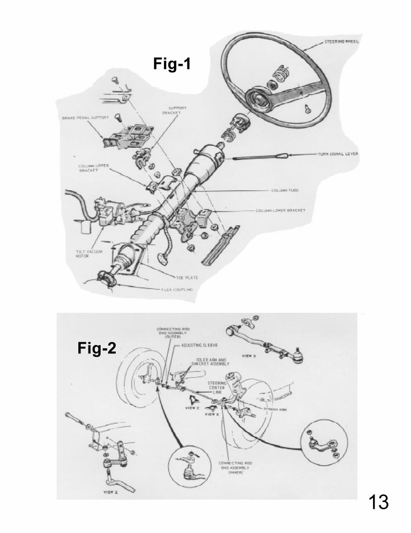
Fig-1
Fig-2
13