rci510 400 calibration
TRANSCRIPT
GREER COMPANY Crane Systems
GREER COMPANY 1918 East Glenwood Place, Santa Ana, CA 92705 TEL: (714) 259-9702 FAX: (714) 259-7626 MicroGuard® RCI 510/400 CALIBRATION MANUAL PN W450189A 09/09/02
1 of 65
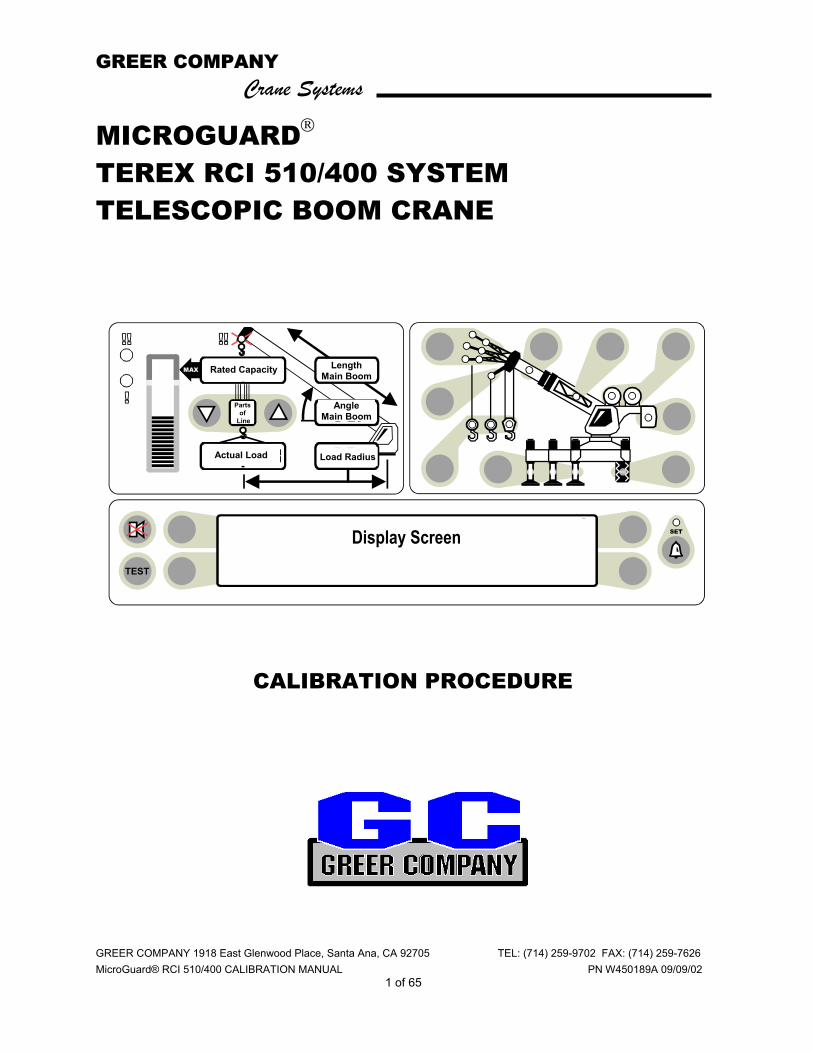
MICROGUARD TEREX RCI 510/400 SYSTEM TELESCOPIC BOOM CRANE
CALIBRATION PROCEDURE
ORs Full 9.7Klb Ctwt ERECTED 60' TELEJIB 17 AUXHD ONPICK FROM MAIN BOOM FRONT WINCH
TEST
MAX
SET 360o
6
23,500
i2,300
44.8
62.7
26.4
o
Rated Capacity
Actual Load
Length Main Boom
Angle Main Boom
Load Radius
Parts of
Line
Display Screen

GREER COMPANY Crane Systems
GREER COMPANY 1918 East Glenwood Place, Santa Ana, CA 92705 TEL: (714) 259-9702 FAX: (714) 259-7626 MicroGuard® RCI 500 CALIBRATION PROCEDURE PN W450189A 09/09/02
2 of 65
MICROGUARD TEREX RCI 510/400 SYSTEM TELESCOPIC BOOM CRANE
CONTENTS
PRE-CALIBRATION REQUIREMENTS ..................................................................................................... 4
OVERVIEW..............................................................................................................................................4-5
THE CAL SWITCH...................................................................................................................................... 5
ENTERING THE CALIBRATION MODE .................................................................................................... 6
ENTERING THE CALIBRATION SECURITY CODE ......................................................................... 6
USING THE DISPLAY KEYS IN COMMAND ROUTINES ......................................................................... 7
COMMAND 00 RUN ................................................................................................................................... 8
COMMAND 01 PERSONALITY................................................................................................................ 9
COMMAND 01/2 INITIALIZE .................................................................................................................... 10
COMMAND 01/0 SAVE............................................................................................................................. 11
COMMAND 02 TEST/FAULT ..............................................................................................................12-13
NUMBER ENTRY ..................................................................................................................................... 14
COMMAND 03 ZERO ............................................................................................................................... 15
ZERO PRESSURE TRANSDUCERS..........................................................................................16-17
ZERO EXTENSION SENSOR .....................................................................................................18-19
ZERO BOOM ANGLE SENSOR..................................................................................................20-21
COMMAND 04 SPAN ............................................................................................................................... 22
BOOM ANGLE SENSOR.............................................................................................................22-23
EXTENSION SENSOR ..................................................................................................................... 24
COMMAND 05 SWING............................................................................................................................. 25
SCALE .............................................................................................................................................. 26
ZERO ................................................................................................................................................ 27
DIRECTION ...................................................................................................................................... 28
CONFIGURATION SELECTION .........................................................................................................29-33
GREER COMPANY Crane Systems
GREER COMPANY 1918 East Glenwood Place, Santa Ana, CA 92705 TEL: (714) 259-9702 FAX: (714) 259-7626 MicroGuard® RCI 510/400 CALIBRATION MANUAL PN W450189A 09/09/02
3 of 65
COMMAND 06 PRESSURE ................................................................................................................34-36
COMMAND 07 RADIUS/MOMENT – MAIN BOOM ............................................................................37-41
RADIUS MOMENT – MAIN BOOM + MANUAL..........................................................................42-45
COMMAND 08 BOOM DEFLECTION CORRECTION............................................................................. 46
COMMAND 09 ANNULAR GAIN.............................................................................................................. 47
COMMAND 12 WINCHES ........................................................................................................................ 48
COMMAND 13 ATTACHMENTS.............................................................................................................. 48
COMMAND 14 BOOM HEAD .............................................................................................................. 49-50
COMMAND 15 ALARM LIMITS ........................................................................................................... 51-53
COMMAND 16 ROPE DATA ............................................................................................................... 54-56
COMMAND 17 AMPLIFIER GAIN ............................................................................................................ 57
COMMAND 01 BACKUP .......................................................................................................................... 57
SWITCH OFF POWER TO THE SYSTEM............................................................................................... 58
COMMAND 01/4 RESTORE..................................................................................................................... 58
COMMAND 19 DIGITAL INPUTS............................................................................................................. 59
GLOSSARY ......................................................................................................................................... 60-64

GREER COMPANY Crane Systems
GREER COMPANY 1918 East Glenwood Place, Santa Ana, CA 92705 TEL: (714) 259-9702 FAX: (714) 259-7626 MicroGuard® RCI 510/400 CALIBRATION MANUAL PN W450189A 09/09/02
4 of 65
MICROGUARD TEREX RCI 510/400 SYSTEM TELESCOPIC BOOM CRANE PRE-CALIBRATION REQUIREMENTS
Following satisfactory installation of the complete RCI 510/400 System:
♦ Ensure that the system is wired in accordance with the appropriate wiring diagram, which is available upon request from Greer.
♦ Ensure that the crane is on firm and level ground, that the outrigger beams are fully extended, and that the jacks are correctly extended to level the carrier.
♦ Ensure that throughout the procedure any structural or stability limits are not exceeded.
♦ Ensure that any attachments (aux. head, fly, jib, etc.) that can be optionally stowed or erected on the boom during normal operation are removed prior to calibration of the main boom.
♦ Ensure that the computer is fitted with the program and duty chips specified in the installation manual.
Using the RCI 510/400 System display, proceed with the calibration commands, as directed in this manual.
OVERVIEW When accurately calibrated, this System provides the operator with a continuous display of the following:
♦ Rated Load
♦ Actual Load
♦ Bar Graph showing Percentage of Rated Load
♦ Radius of the Load
♦ Boom Angle
♦ Main Boom Length
♦ Working Area
♦ Crane Configuration
The RCI 510/400 Display shown on the cover of this manual identifies where this data will appear. Messages on the display screen provide the operator with visual warnings of conditions that occur during operation of the system. THIS MANUAL PROVIDES STEP-BY-STEP DIRECTIONS FOR EACH COMMAND USED IN THE CALIBRATION OF THE RCI 510/400 SYSTEMS.
GREER COMPANY Crane Systems
GREER COMPANY 1918 East Glenwood Place, Santa Ana, CA 92705 TEL: (714) 259-9702 FAX: (714) 259-7626 MicroGuard® RCI 510/400 CALIBRATION MANUAL PN W450189A 09/09/02
5 of 65
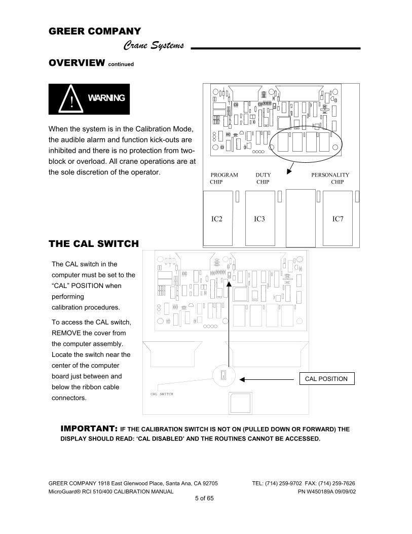
OVERVIEW continued
WARNING !
When the system is in the Calibration Mode, the audible alarm and function kick-outs are inhibited and there is no protection from two-block or overload. All crane operations are at the sole discretion of the operator.
THE CAL SWITCH
CAL SWITCH
PROGRAM
CHIP
DUTY
CHIP
PERSONALITY
CHIP
IC2 IC3 IC7
CAL POSITION
The CAL switch in the computer must be set to the “CAL” POSITION when performing calibration procedures.
To access the CAL switch, REMOVE the cover from the computer assembly. Locate the switch near the center of the computer board just between and below the ribbon cable connectors.
IMPORTANT: IF THE CALIBRATION SWITCH IS NOT ON (PULLED DOWN OR FORWARD) THE DISPLAY SHOULD READ: ‘CAL DISABLED’ AND THE ROUTINES CANNOT BE ACCESSED.
GREER COMPANY Crane Systems
GREER COMPANY 1918 East Glenwood Place, Santa Ana, CA 92705 TEL: (714) 259-9702 FAX: (714) 259-7626 MicroGuard® RCI 510/400 CALIBRATION MANUAL PN W450189A 09/09/02
6 of 65
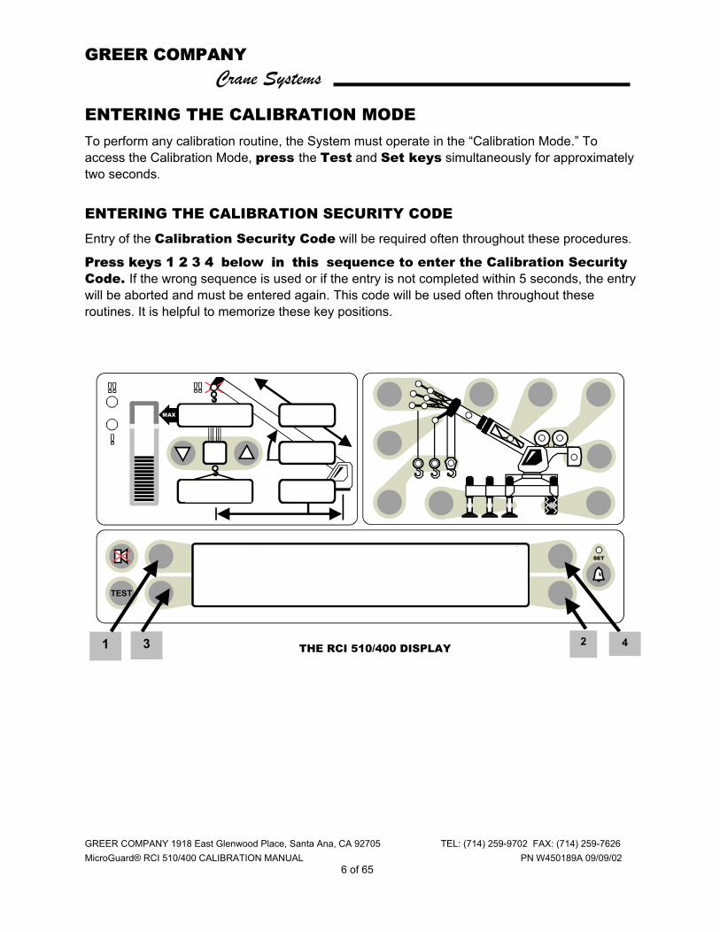
ENTERING THE CALIBRATION MODE To perform any calibration routine, the System must operate in the “Calibration Mode.” To access the Calibration Mode, press the Test and Set keys simultaneously for approximately two seconds.
ENTERING THE CALIBRATION SECURITY CODE
Entry of the Calibration Security Code will be required often throughout these procedures.
Press keys 1 2 3 4 below in this sequence to enter the Calibration Security Code. If the wrong sequence is used or if the entry is not completed within 5 seconds, the entry will be aborted and must be entered again. This code will be used often throughout these routines. It is helpful to memorize these key positions.
ORs Full 9.7Klb Ctwt ERECTED 60' TELEJIB 17 AUXHD ONPICK FROM MAIN BOOM FRONT WINCH
TEST
MAX
SET 360o
6
23,500
i2,300
44.8
62.7
26.4
o
3 2 4 1 THE RCI 510/400 DISPLAY
GREER COMPANY Crane Systems
GREER COMPANY 1918 East Glenwood Place, Santa Ana, CA 92705 TEL: (714) 259-9702 FAX: (714) 259-7626 MicroGuard® RCI 510/400 CALIBRATION MANUAL PN W450189A 09/09/02
7 of 65
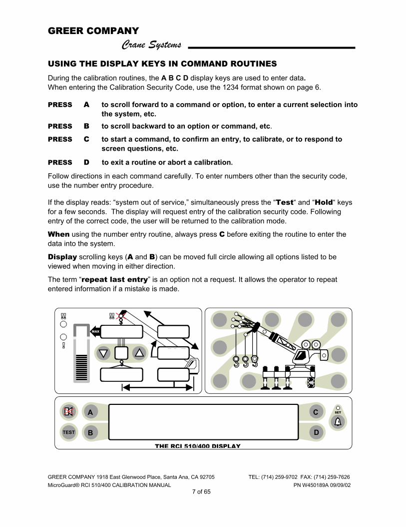
USING THE DISPLAY KEYS IN COMMAND ROUTINES
During the calibration routines, the A B C D display keys are used to enter data. When entering the Calibration Security Code, use the 1234 format shown on page 6.
PRESS A to scroll forward to a command or option, to enter a current selection into the system, etc.
PRESS B to scroll backward to an option or command, etc.
PRESS C to start a command, to confirm an entry, to calibrate, or to respond to screen questions, etc.
PRESS D to exit a routine or abort a calibration.
Follow directions in each command carefully. To enter numbers other than the security code, use the number entry procedure. If the display reads: “system out of service,” simultaneously press the “Test“ and “Hold“ keys for a few seconds. The display will request entry of the calibration security code. Following entry of the correct code, the user will be returned to the calibration mode.
When using the number entry routine, always press C before exiting the routine to enter the data into the system.
Display scrolling keys (A and B) can be moved full circle allowing all options listed to be viewed when moving in either direction.
The term “repeat last entry” is an option not a request. It allows the operator to repeat entered information if a mistake is made.
ORs Full 9.7Klb Ctwt ERECTED 60' TELEJIB 17 AUXHD ONPICK FROM MAIN BOOM FRONT WINCH
TEST
MAX
SET 360o
6
23,500
i2,300
44.8
62.7
26.4
o C
D B
A
THE RCI 510/400 DISPLAY

GREER COMPANY Crane Systems
GREER COMPANY 1918 East Glenwood Place, Santa Ana, CA 92705 TEL: (714) 259-9702 FAX: (714) 259-7626 MicroGuard® RCI 510/400 CALIBRATION MANUAL PN W450189A 09/09/02
8 of 65
COMMAND 00 RUN After accessing the Calibration Mode and entering the Calibration Security Code (see page 6), the system will be in the “Monitor Mode” at Command 00 Run. Do not execute this Command when preparing to calibrate the system; to do so will cause the system to carry out a “system test” followed by a return to the working screen.
Press “A” (menu up) or “B” (menu down) to view all commands. See the illustration on page 7. Stop at Command 01 Personality.
GREER COMPANY Crane Systems
GREER COMPANY 1918 East Glenwood Place, Santa Ana, CA 92705 TEL: (714) 259-9702 FAX: (714) 259-7626 MicroGuard® RCI 510/400 CALIBRATION MANUAL PN W450189A 09/09/02
9 of 65
WARNING !
WARNING !
COMMAND 01 PERSONALITY Command 01 Personality is used to manipulate the crane calibration data. The system stores two sets of data in EEPROM IC7.
“A“ Active Personality (IC7) –contains the data actually used by the main program.
“B“ Backup Personality (IC7) –contains a “protected” copy of the calibration data.
COMMAND 01 FUNCTION
♦ DISPLAYS THE STATUS OF THE PERSONALITY SETS.
♦ MOVES DATA BETWEEN THE TWO SETS.
♦ DELETES DATA FROM THE ACTIVE PERSONALITY.
♦ COPIES DATA TO A BACK-UP CHIP.
♦ RETRIEVES DATA FROM A BACK-UP CHIP.
When the command is first selected (after copying data), both “A” and “B” sets are checked for correct Check-Sum. This is indicated on the display screen by “Good” or “Bad.”
Set “A” is also checked against set “B.” Data that is identical is indicated by “Same” or if not the same, by “Diff.”
Data can be moved using selected sub-commands and the calibration security code. Data entered may also be aborted before completion of the routine. Special care must be taken when working with the sub-commands as some of the sub-commands can cause previously entered data to be
irretrievably lost. SUB-COMMAND 01/0 SAVE SAVES “A” INTO “B” (“B“ DATA IS LOST).
SUB-COMMAND 01/1 XCHG EXCHANGES “A” WITH “B” (DATA IS NOT LOST).
SUB-COMMAND 01/2 INIT INITIALIZES “A” PRIOR TO NEW CALIBRATION (“A“ DATA IS LOST).
SUB-COMMAND 01/3 BACK COPIES THE ACTIVE CALIBRATION TO A BACK-UP CHIP (DATA IS NOT LOST).
SUB-COMMAND 01/4 RETR RETRIEVES THE CALIBRATION FROM A BACK-UP CHIP (PREVIOUS “A“ DATA IS LOST).
Power to the system should be switched off before inserting or removing any integrated circuits. Failure to observe this precaution may cause
permanent damage to the system or its components and result in the loss of calibration data.

GREER COMPANY Crane Systems
GREER COMPANY 1918 East Glenwood Place, Santa Ana, CA 92705 TEL: (714) 259-9702 FAX: (714) 259-7626 MicroGuard® RCI 510/400 CALIBRATION MANUAL PN W450189A 09/09/02
10 of 65
WARNING !
COMMAND 01/2 INITIALIZE
Command 01/2 is used only when calibrating the System for the first time. The use of this command causes all previously entered “A” side calibration data to be erased. If the system has been previously calibrated
and data from a previous calibration is to be accessed or changed, proceed directly to the command to be changed. Do not perform the initialization command below.
COMMAND 01/2 INITIALIZE ROUTINE
This Procedure Completely Erases All Previous Data From “A” Personality. To cancel this routine, PRESS D, ABORT before completing Step 5.
1) PRESS A TO 01 PERSONALITY.
2) PRESS C TO START THE COMMAND.
3) PRESS A TO 2 INIT PERS A ONLY.
4) PRESS C TO START THE CALIBRATION.
5) PRESS C TO CALIBRATE OR PRESS D TO ABORT THE CALIBRATION.
6) PRESS 1234 (CALIBRATION SECURITY CODE)
AFTER THE MESSAGE, “CALIBRATING” ENDS, THE DISPLAY SHOULD READ: “AGOOD BGOOD SAME“ (See page 6).
7) PRESS D TO EXIT ROUTINE. THE SYSTEM WILL RETURN TO THE MONITOR MODE BUT WILL REMAIN IN THE CALIBRATION ROUTINE.
2 Init Pers A Only
ORs Full 9.7Klb Ctwt ERECTED 60' TELEJIB 17 AUXHD ONPICK FROM MAIN BOOM FRONT WINCH
TEST
MAX
SET 360o
6
23,500
i2,300
44.8
62.7
26.4
o C
DB
A 01 Personality

GREER COMPANY Crane Systems
GREER COMPANY 1918 East Glenwood Place, Santa Ana, CA 92705 TEL: (714) 259-9702 FAX: (714) 259-7626 MicroGuard® RCI 510/400 CALIBRATION MANUAL PN W450189A 09/09/02
11 of 65
COMMAND 01/0 SAVE
• If calibrating the entire system, execute Command 01/0 Save after completing each calibration routine to ensure that a complete copy of the calibration data is entered in the backup memory of the system.
• If modifying or correcting an existing calibration, do not save until satisfied with the results of the calibration.
This Command can be used at any time to ensure that data entered up to the time that this routine is completed will be saved in the system.
COMMAND 01/0 SAVE ROUTINE
(applicable to all calibration routines in this manual)
1) PRESS A TO 01 PERSONALITY.
2) PRESS C TO START THE COMMAND.
3) PRESS A TO 01/0 SAVE.
4) PRESS C TO START THE CALIBRATION.
5) PRESS C TO CALIBRATE OR PRESS D TO ABORT THE CALIBRATION.
6) PRESS 1234 (SECURITY CODE).
7) AFTER MESSAGE, “CALIBRATING” ENDS, PRESS D TO EXIT THE ROUTINE.
GREER COMPANY Crane Systems
GREER COMPANY 1918 East Glenwood Place, Santa Ana, CA 92705 TEL: (714) 259-9702 FAX: (714) 259-7626 MicroGuard® RCI 510/400 CALIBRATION MANUAL PN W450189A 09/09/02
12 of 65
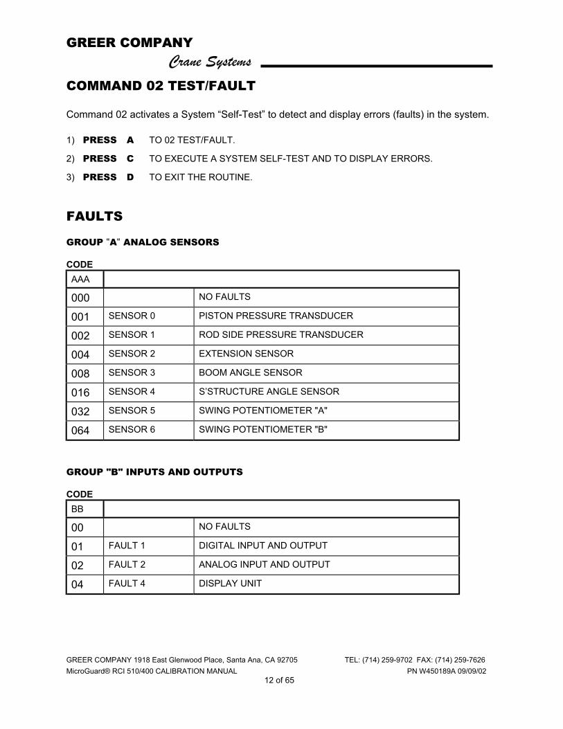
COMMAND 02 TEST/FAULT Command 02 activates a System “Self-Test” to detect and display errors (faults) in the system. 1) PRESS A TO 02 TEST/FAULT.
2) PRESS C TO EXECUTE A SYSTEM SELF-TEST AND TO DISPLAY ERRORS.
3) PRESS D TO EXIT THE ROUTINE. FAULTS GROUP “A“ ANALOG SENSORS CODE AAA
000 NO FAULTS
001 SENSOR 0 PISTON PRESSURE TRANSDUCER
002 SENSOR 1 ROD SIDE PRESSURE TRANSDUCER
004 SENSOR 2 EXTENSION SENSOR
008 SENSOR 3 BOOM ANGLE SENSOR
016 SENSOR 4 S’STRUCTURE ANGLE SENSOR
032 SENSOR 5 SWING POTENTIOMETER "A"
064 SENSOR 6 SWING POTENTIOMETER "B"
GROUP "B" INPUTS AND OUTPUTS CODE BB
00 NO FAULTS
01 FAULT 1 DIGITAL INPUT AND OUTPUT
02 FAULT 2 ANALOG INPUT AND OUTPUT
04 FAULT 4 DISPLAY UNIT
GREER COMPANY Crane Systems
GREER COMPANY 1918 East Glenwood Place, Santa Ana, CA 92705 TEL: (714) 259-9702 FAX: (714) 259-7626 MicroGuard® RCI 510/400 CALIBRATION MANUAL PN W450189A 09/09/02
13 of 65
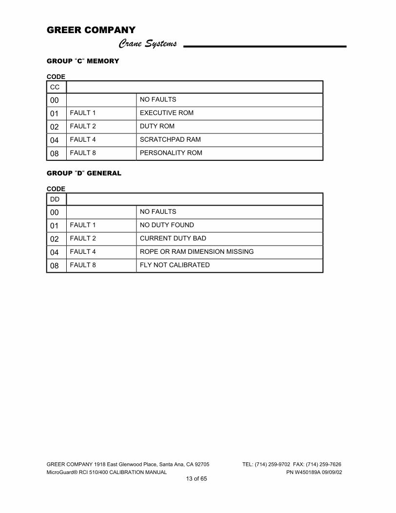
GROUP “C“ MEMORY CODE CC
00 NO FAULTS
01 FAULT 1 EXECUTIVE ROM
02 FAULT 2 DUTY ROM
04 FAULT 4 SCRATCHPAD RAM
08 FAULT 8 PERSONALITY ROM
GROUP “D“ GENERAL CODE DD
00 NO FAULTS
01 FAULT 1 NO DUTY FOUND
02 FAULT 2 CURRENT DUTY BAD
04 FAULT 4 ROPE OR RAM DIMENSION MISSING
08 FAULT 8 FLY NOT CALIBRATED

GREER COMPANY Crane Systems
GREER COMPANY 1918 East Glenwood Place, Santa Ana, CA 92705 TEL: (714) 259-9702 FAX: (714) 259-7626 MicroGuard® RCI 510/400 CALIBRATION MANUAL PN W450189A 09/09/02
14 of 65
NUMBER ENTRY The Microguard RCI 500 does not have number entry keys. When numerical entry of data is required, the display will change to allow the entry of numbers.
• A strip like the one below will appear with numerals from 0 to 9 followed by the three symbols shown.
• The upper left corner identifies the Command (in this case, 06 Pressure). The upper right displays each numeral as entered until the complete number to be calibrated appears, including decimals and minus sign.
• The keys operate as in the calibration routines (A B C D).
1) When the number entry panal appears, the selectors < > will surround the zero < 0 >
numeral which will be flashing. Use “key B” or “key D” to select a numeral. If key B is pressed, the cursor will jump to the opposite end of the display panel and the selectors will surround the minus sign. With each press of key B the cursor will backtrack by one digit toward the original site 0 (zero). When key D is used, the identical process occurs in reverse.
2) When not at the starting point (“0“ or “-“), pressing key B or key D will cause the cursor to move one digit at a time toward its original site. Example: if the cursor were flashing at numeral 5, pressing key B once would cause the cursor to move one digit toward 0 (zero).
3) WHEN ENTERING A MINUS SIGN FOR A NEGATIVE VALUE, ALWAYS DO SO AFTER ALL NUMERALS HAVE BEEN SELECTED.
4) As each digit is selected, press key A to enter it into the system. The numeral will then appear in the upper right bracket. Continue entering numerals and decimal point, as appropriate, until the complete number appears in the upper right box. A total of five digits may be entered in this way.
5) If an error is made when entering a numeral, immediately select the “less than” symbol (<) and press key A. The number should be removed from the right upper selection box. Numbers can be removed this way one digit at a time.
6) When all digits look correct, press key C to calibrate the complete number.
06 Pressure ( 1.0 ) Calibration Load 0 1 2 3 4 5 6 7 8 9 < <·> -
GREER COMPANY Crane Systems
GREER COMPANY 1918 East Glenwood Place, Santa Ana, CA 92705 TEL: (714) 259-9702 FAX: (714) 259-7626 MicroGuard® RCI 510/400 CALIBRATION MANUAL PN W450189A 09/09/02
15 of 65
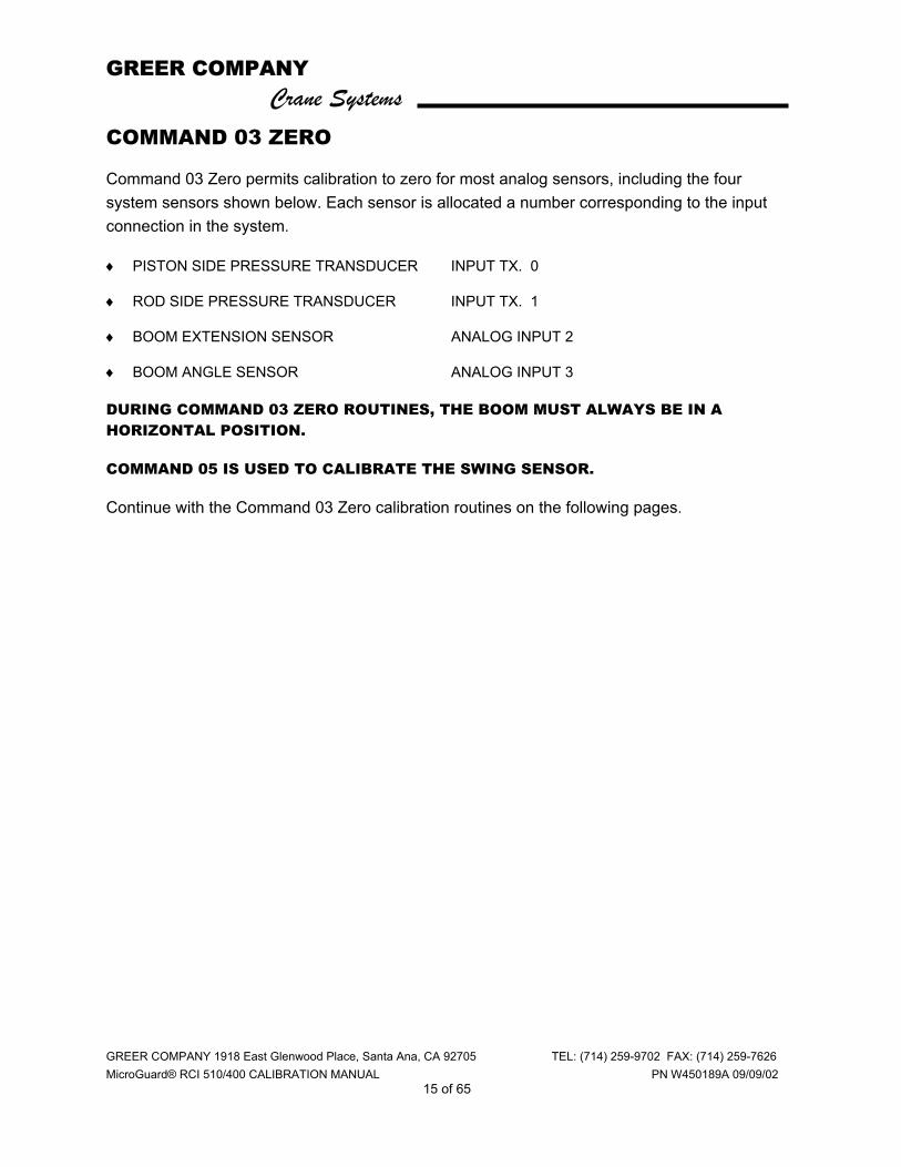
COMMAND 03 ZERO Command 03 Zero permits calibration to zero for most analog sensors, including the four system sensors shown below. Each sensor is allocated a number corresponding to the input connection in the system. ♦ PISTON SIDE PRESSURE TRANSDUCER INPUT TX. 0
♦ ROD SIDE PRESSURE TRANSDUCER INPUT TX. 1
♦ BOOM EXTENSION SENSOR ANALOG INPUT 2
♦ BOOM ANGLE SENSOR ANALOG INPUT 3
DURING COMMAND 03 ZERO ROUTINES, THE BOOM MUST ALWAYS BE IN A HORIZONTAL POSITION.
COMMAND 05 IS USED TO CALIBRATE THE SWING SENSOR.
Continue with the Command 03 Zero calibration routines on the following pages.

GREER COMPANY Crane Systems
GREER COMPANY 1918 East Glenwood Place, Santa Ana, CA 92705 TEL: (714) 259-9702 FAX: (714) 259-7626 MicroGuard® RCI 510/400 CALIBRATION MANUAL PN W450189A 09/09/02
16 of 65
COMMAND 03 ZERO - PRESSURE TRANSDUCERS ♦ Lower the boom until its lower end stops (boom hoist cylinder fully retracted). The boom
must be in a horizontal position when performing the zero routines.
♦ Stop the hydraulic pump and reconnect electrical power to the system.
♦ With the boom hoist cylinder fully retracted, depressurize the hydraulic tank and open the hydraulic lines to the pressure transducers until no pressure remains in the boom hoist cylinders.
♦ With the pressure transducers open to atmosphere, calibrate the zero of the piston and rod pressure transducers, as shown on the next page.
IMPORTANT: Ensure that the boom is in a horizontal position when performing all zero routines.
GREER COMPANY Crane Systems
GREER COMPANY 1918 East Glenwood Place, Santa Ana, CA 92705 TEL: (714) 259-9702 FAX: (714) 259-7626 MicroGuard® RCI 510/400 CALIBRATION MANUAL PN W450189A 09/09/02
17 of 65
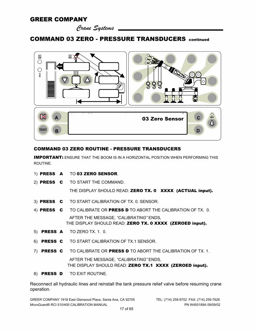
COMMAND 03 ZERO - PRESSURE TRANSDUCERS continued
COMMAND 03 ZERO ROUTINE - PRESSURE TRANSDUCERS
IMPORTANT: ENSURE THAT THE BOOM IS IN A HORIZONTAL POSITION WHEN PERFORMING THIS ROUTINE. 1) PRESS A TO 03 ZERO SENSOR.
2) PRESS C TO START THE COMMAND.
THE DISPLAY SHOULD READ: ZERO TX. 0 XXXX (ACTUAL input).
3) PRESS C TO START CALIBRATION OF TX. 0. SENSOR.
4) PRESS C TO CALIBRATE OR PRESS D TO ABORT THE CALIBRATION OF TX. 0.
AFTER THE MESSAGE, “CALIBRATING” ENDS, THE DISPLAY SHOULD READ: ZERO TX. 0 XXXX (ZEROED input).
5) PRESS A TO ZERO TX. 1. 0.
6) PRESS C TO START CALIBRATION OF TX.1 SENSOR.
7) PRESS C TO CALIBRATE OR PRESS D TO ABORT THE CALIBRATION OF TX. 1.
AFTER THE MESSAGE, “CALIBRATING” ENDS, THE DISPLAY SHOULD READ: ZERO TX.1 XXXX (ZEROED input).
8) PRESS D TO EXIT ROUTINE. Reconnect all hydraulic lines and reinstall the tank pressure relief valve before resuming crane operation.
ORs Full 9.7Klb Ctwt ERECTED 60' TELEJIB 17 AUXHD ONPICK FROM MAIN BOOM FRONT WINCH
TEST
MAX
SET 360o
6
23,500
i2,300
44.8
62.7
26.4
oC
D B
A 03 Zero Sensor

GREER COMPANY Crane Systems
GREER COMPANY 1918 East Glenwood Place, Santa Ana, CA 92705 TEL: (714) 259-9702 FAX: (714) 259-7626 MicroGuard® RCI 510/400 CALIBRATION MANUAL PN W450189A 09/09/02
18 of 65
COMMAND 03 ZERO - EXTENSION SENSOR The extension reel, fitted with 130 ft. of shielded 2-wire cable, cannot be shortened to accommodate varying boom lengths.
IMPORTANT: Ensure that the boom is in a horizontal position when performing this routine.
COMMAND 03 ZERO PRETENSION ROUTINE – EXTENSION SENSOR
1) Fully retract all boom sections.
2) Remove the clamp on the reel cable and allow it to slowly rewind onto the reel until there is no pretension.
3) Continue to rewind the reel until the distance between the attachment point and the end of the cable is approximately 12 ft. Due to the clutch on the reel shaft, there will now be no pre-tension.
4) Pull the cable toward the anchor point, continuing until the end of the cable is 3 ft. Beyond the anchor point.
5) Secure the cable to the anchor point with at least 4 wraps, ensuring that there is sufficient cable at the boom head to connect to the anti two-block switch, which is terminated in a 3-pin plug.
6) Manually turn the large gear on the potentiometer fully counterclockwise. Then, advance the gear clockwise three clicks.
7) Calibrate the zero of the sensor, as shown on the next page.
GREER COMPANY Crane Systems
GREER COMPANY 1918 East Glenwood Place, Santa Ana, CA 92705 TEL: (714) 259-9702 FAX: (714) 259-7626 MicroGuard® RCI 510/400 CALIBRATION MANUAL PN W450189A 09/09/02
19 of 65
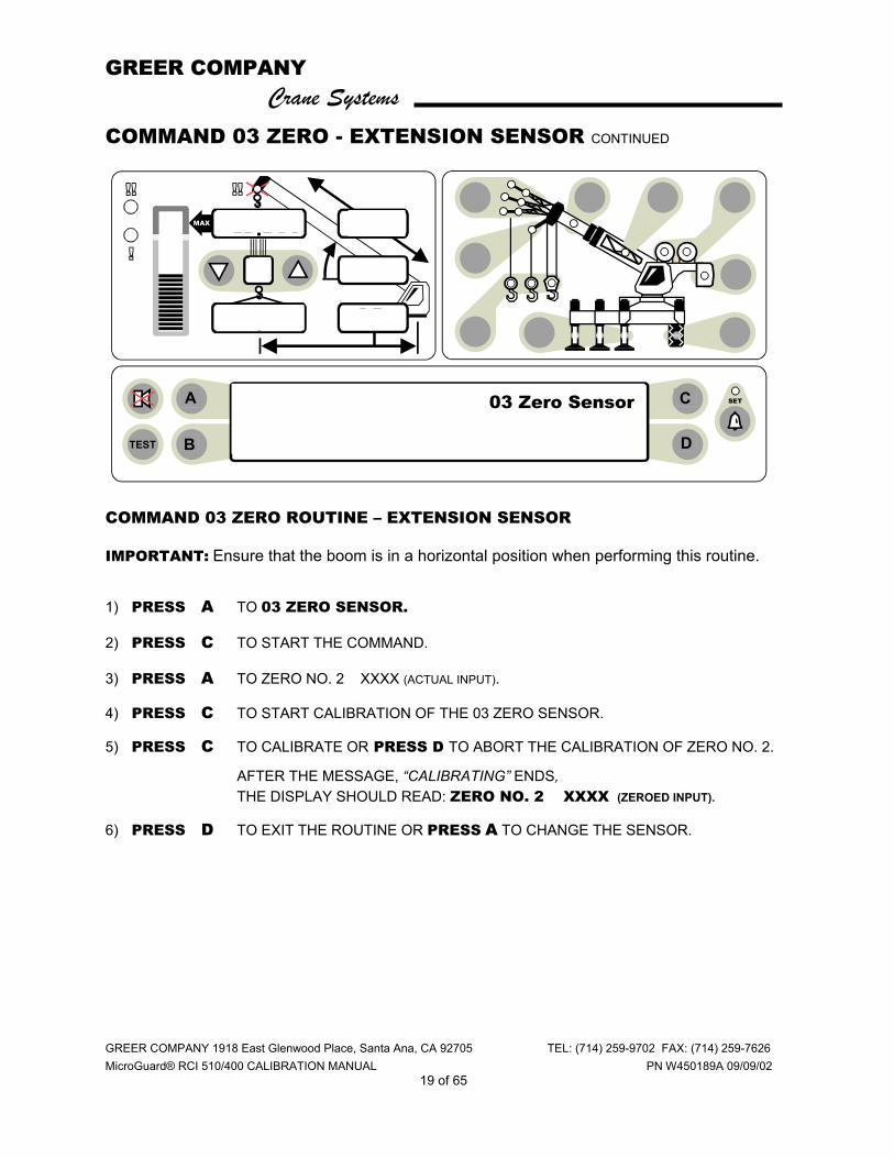
COMMAND 03 ZERO - EXTENSION SENSOR CONTINUED
COMMAND 03 ZERO ROUTINE – EXTENSION SENSOR
IMPORTANT: Ensure that the boom is in a horizontal position when performing this routine.
1) PRESS A TO 03 ZERO SENSOR.
2) PRESS C TO START THE COMMAND.
3) PRESS A TO ZERO NO. 2 XXXX (ACTUAL INPUT).
4) PRESS C TO START CALIBRATION OF THE 03 ZERO SENSOR.
5) PRESS C TO CALIBRATE OR PRESS D TO ABORT THE CALIBRATION OF ZERO NO. 2.
AFTER THE MESSAGE, “CALIBRATING” ENDS, THE DISPLAY SHOULD READ: ZERO NO. 2 XXXX (ZEROED INPUT).
6) PRESS D TO EXIT THE ROUTINE OR PRESS A TO CHANGE THE SENSOR.
ORs Full 9.7Klb Ctwt ERECTED 60' TELEJIB 17 AUXHD ONPICK FROM MAIN BOOM FRONT WINCH
TEST
MAX
SET 360o
6
23,500
i2,300
44.8
62.7
26.4
o C
D B
A 03 Zero Sensor

GREER COMPANY Crane Systems
GREER COMPANY 1918 East Glenwood Place, Santa Ana, CA 92705 TEL: (714) 259-9702 FAX: (714) 259-7626 MicroGuard® RCI 510/400 CALIBRATION MANUAL PN W450189A 09/09/02
20 of 65
COMMAND 03 ZERO - BOOM ANGLE SENSOR Use great care when calibrating the boom angle sensor. All subsequent calculations are dependent on the accuracy of this calibration.
Use an inclinometer or measuring device with an accuracy of +/- 0.25 when calibrating the boom angle sensor. Use of a less accurate device may result in calibration errors.
IMPORTANT: Ensure that the boom is in a horizontal position when performing this routine.
♦ Using an inclinometer, set the boom in a horizontal position.
♦ The boom angle sensor is mounted inside the d3l0022 housing. Mount the extension sensor perpendicular to the boom.
♦ Calibrate the zero of the boom angle sensor (page 21).
GREER COMPANY Crane Systems
GREER COMPANY 1918 East Glenwood Place, Santa Ana, CA 92705 TEL: (714) 259-9702 FAX: (714) 259-7626 MicroGuard® RCI 510/400 CALIBRATION MANUAL PN W450189A 09/09/02
21 of 65
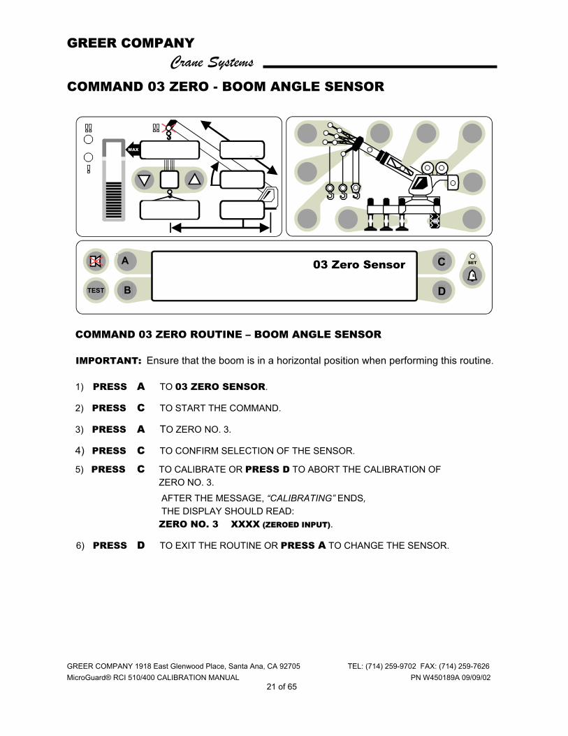
COMMAND 03 ZERO - BOOM ANGLE SENSOR
COMMAND 03 ZERO ROUTINE – BOOM ANGLE SENSOR IMPORTANT: Ensure that the boom is in a horizontal position when performing this routine. 1) PRESS A TO 03 ZERO SENSOR.
2) PRESS C TO START THE COMMAND.
3) PRESS A TO ZERO NO. 3.
4) PRESS C TO CONFIRM SELECTION OF THE SENSOR.
5) PRESS C TO CALIBRATE OR PRESS D TO ABORT THE CALIBRATION OF ZERO NO. 3. AFTER THE MESSAGE, “CALIBRATING” ENDS, THE DISPLAY SHOULD READ: ZERO NO. 3 XXXX (ZEROED INPUT).
6) PRESS D TO EXIT THE ROUTINE OR PRESS A TO CHANGE THE SENSOR.
03 ZERO EXTENSION SENSOR D C A
ORs Full 9.7Klb Ctwt ERECTED 60' TELEJIB 17 AUXHD ONPICK FROM MAIN BOOM FRONT WINCH
TEST
MAX
SET 360o
6
23,500
i2,300
44.8
62.7
26.4
o03 Zero Sensor
B D
C A
GREER COMPANY Crane Systems
GREER COMPANY 1918 East Glenwood Place, Santa Ana, CA 92705 TEL: (714) 259-9702 FAX: (714) 259-7626 MicroGuard® RCI 510/400 CALIBRATION MANUAL PN W450189A 09/09/02
22 of 65
COMMAND 04 SPAN Command 04 Span includes the boom angle sensor and the extension sensor. BOOM ANGLE SENSOR Use great care when calibrating the boom angle sensor. All subsequent calculations are dependent on the accuracy of the calibration of this sensor. ♦ Use an inclinometer or measuring device with an accuracy of +/- 0.25 when calibrating the
angle of the main boom. Use of a less accurate device could result in calibration errors.
♦ Calibrate the span of the boom angle sensor, as shown on the next page.
GREER COMPANY Crane Systems
GREER COMPANY 1918 East Glenwood Place, Santa Ana, CA 92705 TEL: (714) 259-9702 FAX: (714) 259-7626 MicroGuard® RCI 510/400 CALIBRATION MANUAL PN W450189A 09/09/02
23 of 65
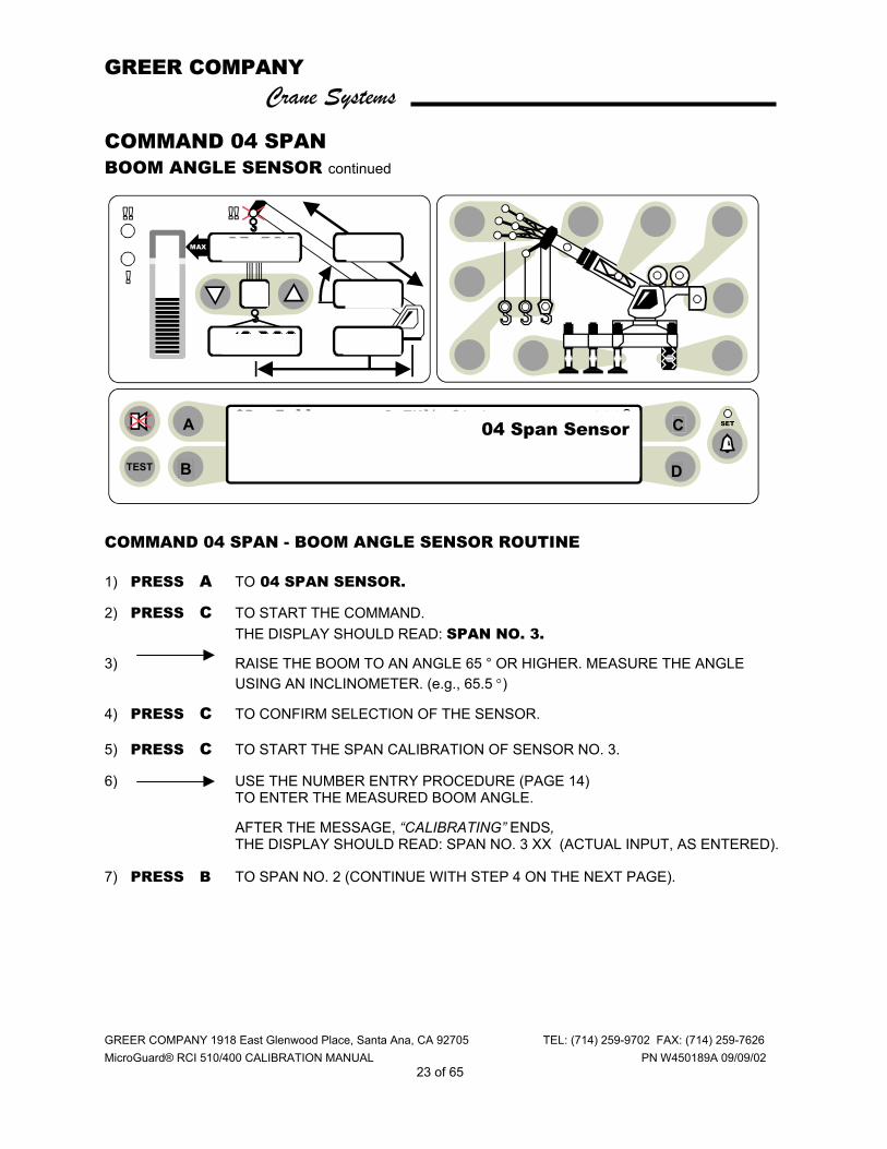
COMMAND 04 SPAN BOOM ANGLE SENSOR continued COMMAND 04 SPAN - BOOM ANGLE SENSOR ROUTINE 1) PRESS A TO 04 SPAN SENSOR.
2) PRESS C TO START THE COMMAND. THE DISPLAY SHOULD READ: SPAN NO. 3.
3) RAISE THE BOOM TO AN ANGLE 65 ° OR HIGHER. MEASURE THE ANGLE USING AN INCLINOMETER. (e.g., 65.5 °)
4) PRESS C TO CONFIRM SELECTION OF THE SENSOR.
5) PRESS C TO START THE SPAN CALIBRATION OF SENSOR NO. 3.
6) USE THE NUMBER ENTRY PROCEDURE (PAGE 14) TO ENTER THE MEASURED BOOM ANGLE.
AFTER THE MESSAGE, “CALIBRATING” ENDS, THE DISPLAY SHOULD READ: SPAN NO. 3 XX (ACTUAL INPUT, AS ENTERED).
7) PRESS B TO SPAN NO. 2 (CONTINUE WITH STEP 4 ON THE NEXT PAGE).
ORs Full 9.7Klb Ctwt ERECTED 60' TELEJIB 17 AUXHD ONPICK FROM MAIN BOOM FRONT WINCH
TEST
MAX
SET 360o
6
23,500
i2,300
44.8
62.7
26.4
o04 Span Sensor
B D
C A
GREER COMPANY Crane Systems
GREER COMPANY 1918 East Glenwood Place, Santa Ana, CA 92705 TEL: (714) 259-9702 FAX: (714) 259-7626 MicroGuard® RCI 510/400 CALIBRATION MANUAL PN W450189A 09/09/02
24 of 65
COMMAND 04 SPAN continued
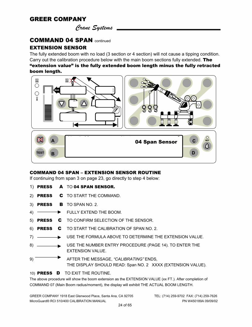
EXTENSION SENSOR The fully extended boom with no load (3 section or 4 section) will not cause a tipping condition. Carry out the calibration procedure below with the main boom sections fully extended. The “extension value” is the fully extended boom length minus the fully retracted boom length. COMMAND 04 SPAN – EXTENSION SENSOR ROUTINE If continuing from span 3 on page 23, go directly to step 4 below:
1) PRESS A TO 04 SPAN SENSOR.
2) PRESS C TO START THE COMMAND.
3) PRESS B TO SPAN NO. 2.
4) FULLY EXTEND THE BOOM.
5) PRESS C TO CONFIRM SELECTION OF THE SENSOR.
6) PRESS C TO START THE CALIBRATION OF SPAN NO. 2.
7) USE THE FORMULA ABOVE TO DETERMINE THE EXTENSION VALUE.
8) USE THE NUMBER ENTRY PROCEDURE (PAGE 14). TO ENTER THE EXTENSION VALUE.
9) AFTER THE MESSAGE, “CALIBRATING” ENDS, THE DISPLAY SHOULD READ: Span NO. 2 XXXX (EXTENSION VALUE).
10) PRESS D TO EXIT THE ROUTINE. The above procedure will show the boom extension as the EXTENSION VALUE (xx FT.). After completion of COMMAND 07 (Main Boom radius/moment), the display will exhibit THE ACTUAL BOOM LENGTH.
ORs Full 9.7Klb Ctwt ERECTED 60' TELEJIB 17 AUXHD ONPICK FROM MAIN BOOM FRONT WINCH
TEST
MAX
SET 360o
6
23,500
i2,300
44.8
62.7
26.4
o04 Span Sensor
B D
C A
GREER COMPANY Crane Systems
GREER COMPANY 1918 East Glenwood Place, Santa Ana, CA 92705 TEL: (714) 259-9702 FAX: (714) 259-7626 MicroGuard® RCI 510/400 CALIBRATION MANUAL PN W450189A 09/09/02
25 of 65
COMMAND 05 SWING Perform this Command ONLY if the crane has a swing potentiometer.
Command 05 includes the scale, zero, and direction routines. These routines are usually carried out consecutively. However, zero and direction can be done in isolation of scale. When scale is redone, zero and direction must follow. SCALE Command 05 does not require the entry of measured data. Measurements of swing data are acquired automatically during the calibration of the swing sensor. However, it is essential that the crane upper be rotated slowly during this procedure. ZERO To obtain the data required for the zero of the potentiometer, the crane upper must be directly in line over the front of the crane. This applies to all crane models, lattice or hydraulic and truck or all terrain. DIRECTION
Swing direction is similar to a compass. Swinging to the right increases the readings and swinging to the left decreases the readings. If the swing potentiometer is mounted so that output is in the wrong direction, use the direction command to change the displayed direction.
GREER COMPANY Crane Systems
GREER COMPANY 1918 East Glenwood Place, Santa Ana, CA 92705 TEL: (714) 259-9702 FAX: (714) 259-7626 MicroGuard® RCI 510/400 CALIBRATION MANUAL PN W450189A 09/09/02
26 of 65
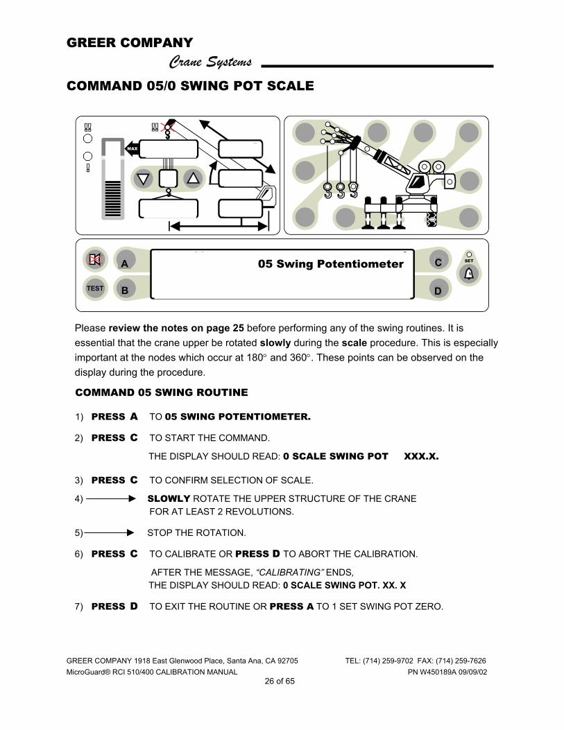
COMMAND 05/0 SWING POT SCALE
Please review the notes on page 25 before performing any of the swing routines. It is essential that the crane upper be rotated slowly during the scale procedure. This is especially important at the nodes which occur at 180° and 360°. These points can be observed on the display during the procedure.
COMMAND 05 SWING ROUTINE
1) PRESS A TO 05 SWING POTENTIOMETER.
2) PRESS C TO START THE COMMAND.
THE DISPLAY SHOULD READ: 0 SCALE SWING POT XXX.X.
3) PRESS C TO CONFIRM SELECTION OF SCALE.
4) SLOWLY ROTATE THE UPPER STRUCTURE OF THE CRANE FOR AT LEAST 2 REVOLUTIONS.
5) STOP THE ROTATION.
6) PRESS C TO CALIBRATE OR PRESS D TO ABORT THE CALIBRATION.
AFTER THE MESSAGE, “CALIBRATING” ENDS, THE DISPLAY SHOULD READ: 0 SCALE SWING POT. XX. X
7) PRESS D TO EXIT THE ROUTINE OR PRESS A TO 1 SET SWING POT ZERO.
ORs Full 9.7Klb Ctwt ERECTED 60' TELEJIB 17 AUXHD ONPICK FROM MAIN BOOM FRONT WINCH
TEST
MAX
SET 360o
6
23,500
i2,300
44.8
62.7
26.4
o05 Swing Potentiometer
B D
C A
GREER COMPANY Crane Systems
GREER COMPANY 1918 East Glenwood Place, Santa Ana, CA 92705 TEL: (714) 259-9702 FAX: (714) 259-7626 MicroGuard® RCI 510/400 CALIBRATION MANUAL PN W450189A 09/09/02
27 of 65
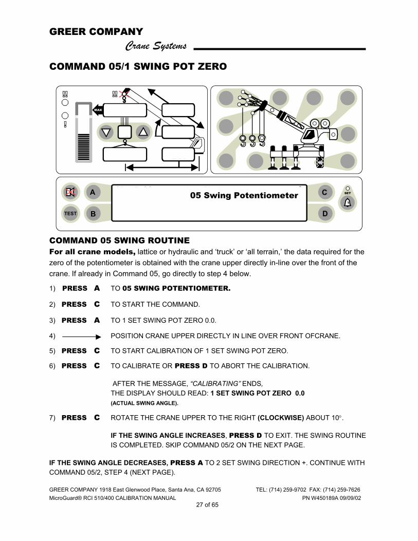
COMMAND 05/1 SWING POT ZERO
COMMAND 05 SWING ROUTINE For all crane models, lattice or hydraulic and ‘truck’ or ‘all terrain,’ the data required for the zero of the potentiometer is obtained with the crane upper directly in-line over the front of the crane. If already in Command 05, go directly to step 4 below.
1) PRESS A TO 05 SWING POTENTIOMETER.
2) PRESS C TO START THE COMMAND.
3) PRESS A TO 1 SET SWING POT ZERO 0.0.
4) POSITION CRANE UPPER DIRECTLY IN LINE OVER FRONT OFCRANE.
5) PRESS C TO START CALIBRATION OF 1 SET SWING POT ZERO.
6) PRESS C TO CALIBRATE OR PRESS D TO ABORT THE CALIBRATION.
AFTER THE MESSAGE, “CALIBRATING” ENDS, THE DISPLAY SHOULD READ: 1 SET SWING POT ZERO 0.0 (ACTUAL SWING ANGLE).
7) PRESS C ROTATE THE CRANE UPPER TO THE RIGHT (CLOCKWISE) ABOUT 10°.
IF THE SWING ANGLE INCREASES, PRESS D TO EXIT. THE SWING ROUTINE IS COMPLETED. SKIP COMMAND 05/2 ON THE NEXT PAGE.
IF THE SWING ANGLE DECREASES, PRESS A TO 2 SET SWING DIRECTION +. CONTINUE WITH COMMAND 05/2, STEP 4 (NEXT PAGE).
ORs Full 9.7Klb Ctwt ERECTED 60' TELEJIB 17 AUXHD ONPICK FROM MAIN BOOM FRONT WINCH
TEST
MAX
SET 360o
6
23,500
i2,300
44.8
62.7
26.4
o05 Swing Potentiometer
B D
C A
GREER COMPANY Crane Systems
GREER COMPANY 1918 East Glenwood Place, Santa Ana, CA 92705 TEL: (714) 259-9702 FAX: (714) 259-7626 MicroGuard® RCI 510/400 CALIBRATION MANUAL PN W450189A 09/09/02
28 of 65
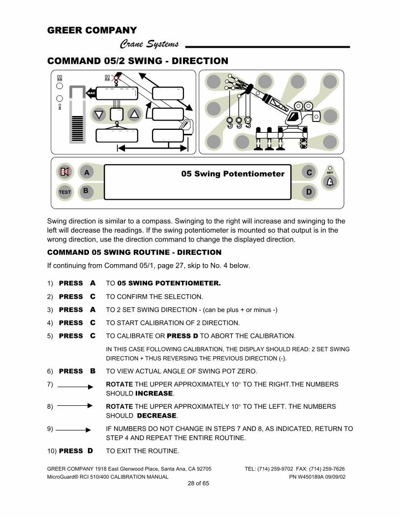
COMMAND 05/2 SWING - DIRECTION Swing direction is similar to a compass. Swinging to the right will increase and swinging to the left will decrease the readings. If the swing potentiometer is mounted so that output is in the wrong direction, use the direction command to change the displayed direction.
COMMAND 05 SWING ROUTINE - DIRECTION
If continuing from Command 05/1, page 27, skip to No. 4 below.
1) PRESS A TO 05 SWING POTENTIOMETER.
2) PRESS C TO CONFIRM THE SELECTION.
3) PRESS A TO 2 SET SWING DIRECTION - (can be plus + or minus -)
4) PRESS C TO START CALIBRATION OF 2 DIRECTION.
5) PRESS C TO CALIBRATE OR PRESS D TO ABORT THE CALIBRATION.
IN THIS CASE FOLLOWING CALIBRATION, THE DISPLAY SHOULD READ: 2 SET SWING DIRECTION + THUS REVERSING THE PREVIOUS DIRECTION (-).
6) PRESS B TO VIEW ACTUAL ANGLE OF SWING POT ZERO.
7) ROTATE THE UPPER APPROXIMATELY 10° TO THE RIGHT.THE NUMBERS SHOULD INCREASE.
8) ROTATE THE UPPER APPROXIMATELY 10° TO THE LEFT. THE NUMBERS SHOULD DECREASE.
9) IF NUMBERS DO NOT CHANGE IN STEPS 7 AND 8, AS INDICATED, RETURN TO STEP 4 AND REPEAT THE ENTIRE ROUTINE.
10) PRESS D TO EXIT THE ROUTINE.
ORs Full 9.7Klb Ctwt ERECTED 60' TELEJIB 17 AUXHD ONPICK FROM MAIN BOOM FRONT WINCH
TEST
MAX
SET 360o
6
23,500
i2,300
44.8
62.7
26.4
o05 Swing Potentiometer
B D
C A
GREER COMPANY Crane Systems
GREER COMPANY 1918 East Glenwood Place, Santa Ana, CA 92705 TEL: (714) 259-9702 FAX: (714) 259-7626 MicroGuard® RCI 510/400 CALIBRATION MANUAL PN W450189A 09/09/02
29 of 65
Cranes equipped with one winch can omit No. 5, but still require a lifting point selection when 2 or more lift point options exist. Note: Any stowable attachment (stowed or not stowed) that will be selected for erection must first be selected as ‘stowed.’
CONFIGURATION SELECTION Before proceeding with further calibrations, ensure that the crane configuration setup is correct and that the calibration configuration selection is correct.
♦ The system automatically chooses the configuration last selected each time the system is powered up.
♦ The system automatically records the configuration last selected when in the normal operational mode.
♦ If changes have been made to the crane configuration, return to the normal operational mode and reenter the crane configuration data applicable to the area of change before calibrating.
♦ When changes are made after the initial calibration, only the area(s) relating to the change will require recalibration.
♦ When calibrating the main boom, always select “lifting over the main boom.” All calibrations pertaining to the main boom require that the operator lift and measure from the main boom.
♦ If there is a stowed attachment on the boom, select it on the display as “stowed.” If nothing is stowed, select “nothing stowed.”
ACCESSING THE NORMAL OPERATIONAL MODE
Press A to Command 01 Run. A system safety check will begin followed by a printed warning message and a return to the normal operational mode.
or Press Exit repeatedly until it no longer says “Exit” to access the normal operational mode.
CRANE SET UP CATEGORIES
Review the operator’s manual and the following categories before starting the crane setup routine on page 31.
1) Outriggers, tires, rigging/travel mode.
2) Applicable to cranes with multiple boom mode selections: active tip, modes A & B, main boom + manual, etc. If the crane has no boom options other than the main boom, skip this step.
3) Auxiliary head, fitted or not fitted.
4) Erected attachments (see notes below).
5) Lifting point for front winch.
6) Lifting point for rear winch.
GREER COMPANY Crane Systems
GREER COMPANY 1918 East Glenwood Place, Santa Ana, CA 92705 TEL: (714) 259-9702 FAX: (714) 259-7626 MicroGuard® RCI 510/400 CALIBRATION MANUAL PN W450189A 09/09/02
30 of 65
ORs Full 9.7Klb Ctwt ERECTED 60' TELEJIB 17 AUXHD ONPICK FROM MAIN BOOM FRONT WINCH
TEST
MAX
SET 360o
6
23,500
i2,300
44.8
62.7
26.4
o
CONFIGURATION SELECTION continued
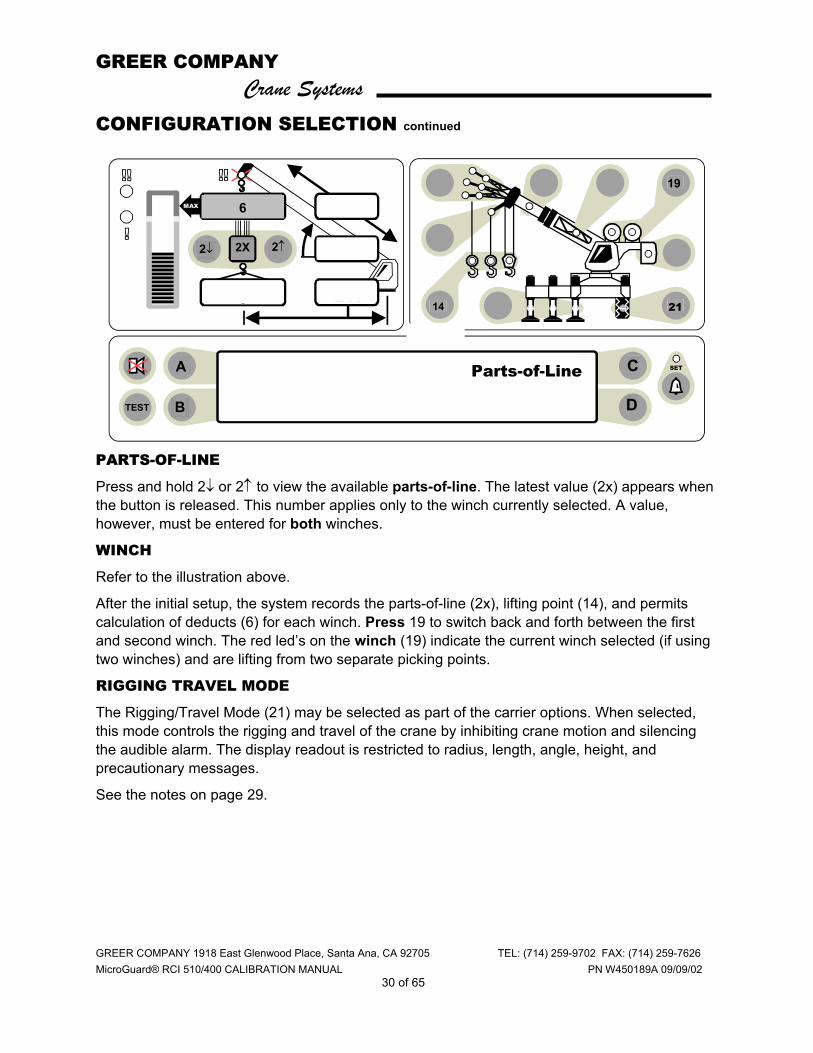
PARTS-OF-LINE
Press and hold 2↓ or 2↑ to view the available parts-of-line. The latest value (2x) appears when the button is released. This number applies only to the winch currently selected. A value, however, must be entered for both winches.
WINCH
Refer to the illustration above.
After the initial setup, the system records the parts-of-line (2x), lifting point (14), and permits calculation of deducts (6) for each winch. Press 19 to switch back and forth between the first and second winch. The red led’s on the winch (19) indicate the current winch selected (if using two winches) and are lifting from two separate picking points.
RIGGING TRAVEL MODE
The Rigging/Travel Mode (21) may be selected as part of the carrier options. When selected, this mode controls the rigging and travel of the crane by inhibiting crane motion and silencing the audible alarm. The display readout is restricted to radius, length, angle, height, and precautionary messages.
See the notes on page 29.
B
2↑
19
21
2↓ 2X
14
Parts-of-Line
D
C A
6
GREER COMPANY Crane Systems
GREER COMPANY 1918 East Glenwood Place, Santa Ana, CA 92705 TEL: (714) 259-9702 FAX: (714) 259-7626 MicroGuard® RCI 510/400 CALIBRATION MANUAL PN W450189A 09/09/02
31 of 65
ORs Full 9.7Klb Ctwt ERECTED 60' TELEJIB 17 AUXHD ONPICK FROM MAIN BOOM FRONT WINCH
TEST
MAX
SET 360o
6
23,500
i2,300
44.8
62.7
26.4
o
CONFIGURATION SELECTION continued
STEPS FOR CRANE SETUP
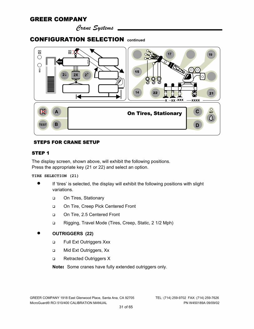
STEP 1
The display screen, shown above, will exhibit the following positions. Press the appropriate key (21 or 22) and select an option.
TIRE SELECTION (21)
• If ‘tires’ is selected, the display will exhibit the following positions with slight variations.
On Tires, Stationary
On Tire, Creep Pick Centered Front
On Tire, 2.5 Centered Front
Rigging, Travel Mode (Tires, Creep, Static, 2 1/2 Mph)
• OUTRIGGERS (22)
Full Ext Outriggers Xxx
Mid Ext Outriggers, Xx
Retracted Outriggers X
Note: Some cranes have fully extended outriggers only.
B
19 17
22
xx xxx xxxx
15
B
2↑
21
2↓ 2X
14
On Tires, Stationary
D
C A
x
GREER COMPANY Crane Systems
GREER COMPANY 1918 East Glenwood Place, Santa Ana, CA 92705 TEL: (714) 259-9702 FAX: (714) 259-7626 MicroGuard® RCI 510/400 CALIBRATION MANUAL PN W450189A 09/09/02
32 of 65
CONFIGURATION SELECTION continued
STEP 2 Your crane may have only the main boom. If so, pressing button 17 on the display may produce the message, “No other boom options available."
PRESS KEY 17.
The display screen SHOULD READ:
♦ MAIN BOOM
♦ MAIN BOOM + MANUAL
Elect an option and press the corresponding key.
STEP 3 PRESS KEY 15 to indicate whether or not the auxiliary head is fitted. If fitted, the display will relay a message and a red lamp will illuminate on the aux head (15).
STEP 4 For the purpose of calibrating, jibs/flys should be stowed or removed from the crane and selected as such on the computer.
Enter data for each attachment on the crane. There are varying options. Enter the type of jib used. Press the key next to the appropriate selection.
JIB SELECTION The display will request the selection of one of the following items.
NO FLY
26’ OFFSET
26’ 43’ TELE JIB
STEP 5 see next page

GREER COMPANY Crane Systems
GREER COMPANY 1918 East Glenwood Place, Santa Ana, CA 92705 TEL: (714) 259-9702 FAX: (714) 259-7626 MicroGuard® RCI 510/400 CALIBRATION MANUAL PN W450189A 09/09/02
33 of 65
CONFIGURATION SELECTION continued
STEP 5 1. Program each of the two winches, front and rear. The selected winch will appear on
the display illuminated by a green light.
2. Identify the lifting point (14) for each winch.
3. Select the number of parts-of-line (2) for each winch to be used.
When both winches are programmed, switch between the lifting points by changing the winch in use (19) on the display.

GREER COMPANY Crane Systems
GREER COMPANY 1918 East Glenwood Place, Santa Ana, CA 92705 TEL: (714) 259-9702 FAX: (714) 259-7626 MicroGuard® RCI 500 CALIBRATION PROCEDURE PN W450189A 09/09/02
34 of 65
COMMAND 06 PRESSURE
IMPORTANT: Command 06 requires special attention. If the routine directions are not followed carefully, other routines in the system can also become invalidated.
1. Select fully extended outriggers, Main Boom, & No. of Attachments (preferably none).
2. Prepare to lift a known calibration load (preferably certified) at a precise angle of 45 °+/- 2 °. Use 90 to 100% of the crane’s capacity (as defined by the crane capacity chart) to put as much pressure as possible on the lift cylinders. This action is accomplished (depending on the capacity chart) by either extending or retracting the boom.
♦ The calibration load includes the weight of the pins and slings but does not include the weight of the block or ball.
♦ When the load is grounded, the slings should also be grounded and not supported by the hook.
♦ When raising and lowering the load, use the winch. Do not use the boom.
♦ Before acquiring data, wait at least 10 seconds for the pressures to become stable. CALIBRATE THE PRESSURE SPAN FOLLOWING THE STEPS ON THE NEXT PAGE.
GREER COMPANY Crane Systems
GREER COMPANY 1918 East Glenwood Place, Santa Ana, CA 92705 TEL: (714) 259-9702 FAX: (714) 259-7626 MicroGuard® RCI 510/400 CALIBRATION MANUAL PN W450189A 09/09/02
35 of 65
COMMAND 06 PRESSURE continued
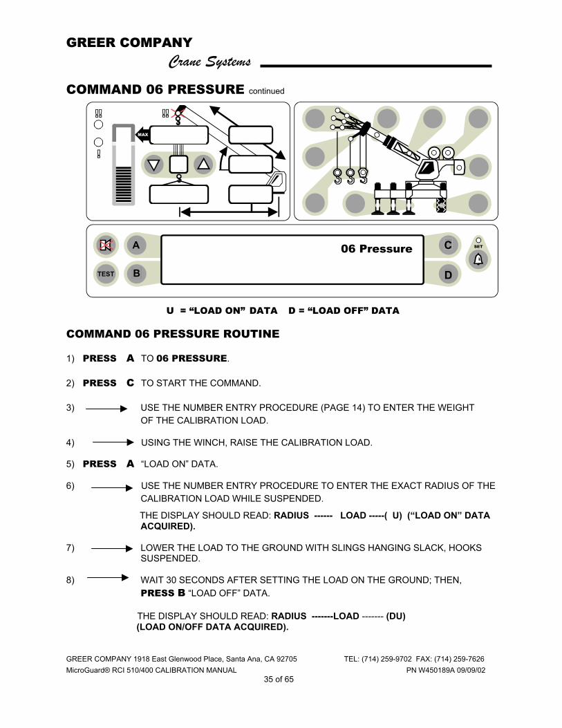
U = “LOAD ON” DATA D = “LOAD OFF” DATA
COMMAND 06 PRESSURE ROUTINE
1) PRESS A TO 06 PRESSURE.
2) PRESS C TO START THE COMMAND.
3) USE THE NUMBER ENTRY PROCEDURE (PAGE 14) TO ENTER THE WEIGHT OF THE CALIBRATION LOAD.
4) USING THE WINCH, RAISE THE CALIBRATION LOAD.
5) PRESS A “LOAD ON” DATA.
6) USE THE NUMBER ENTRY PROCEDURE TO ENTER THE EXACT RADIUS OF THE CALIBRATION LOAD WHILE SUSPENDED.
THE DISPLAY SHOULD READ: RADIUS ------ LOAD -----( U) (“LOAD ON” DATA ACQUIRED).
7) LOWER THE LOAD TO THE GROUND WITH SLINGS HANGING SLACK, HOOKS SUSPENDED.
8) WAIT 30 SECONDS AFTER SETTING THE LOAD ON THE GROUND; THEN, PRESS B “LOAD OFF” DATA.
THE DISPLAY SHOULD READ: RADIUS -------LOAD ------- (DU) (LOAD ON/OFF DATA ACQUIRED).
ORs Full 9.7Klb Ctwt ERECTED 60' TELEJIB 17 AUXHD ONPICK FROM MAIN BOOM FRONT WINCH
TEST
MAX
SET 360o
6
23,500
i2,300
44.8
62.7
26.4
o06 Pressure
B D
C A
GREER COMPANY Crane Systems
GREER COMPANY 1918 East Glenwood Place, Santa Ana, CA 92705 TEL: (714) 259-9702 FAX: (714) 259-7626 MicroGuard® RCI 510/400 CALIBRATION MANUAL PN W450189A 09/09/02
36 of 65
COMMAND 06 PRESSURE continued
COMMAND 06 PRESSURE ROUTINE CONTINUED
9) PRESS C TO START THE LOAD CALIBRATION.
10) PRESS C TO CONFIRM OR PRESS D TO ABORT THE CALIBRATION.
WITH THE LOAD STILL ON THE GROUND, THE LOAD DISPLAY SHOULD READ: “ZERO.”
11) RAISE THE CALIBRATION LOAD.
THE DISPLAY SHOULD READ THE EXACT VALUE OF THE CALIBRATION LOAD, AS ENTERED.
IF THE DISPLAYED LOAD IS NOT THE LOAD ENTERED, REPEAT THE ENTIRE ROUTINE.
12) PRESS D TO EXIT THE ROUTINE.

GREER COMPANY Crane Systems
GREER COMPANY 1918 East Glenwood Place, Santa Ana, CA 92705 TEL: (714) 259-9702 FAX: (714) 259-7626 MicroGuard® RCI 510/400 CALIBRATION MANUAL PN W450189A 09/09/02
37 of 65
COMMAND 07 RADIUS/MOMENT MAIN BOOM COMMAND 07 is used to calibrate the radius and moment of the main boom.
Before starting Command 07, ensure that the crane is appropriately configured and that the related data has been entered into the computer (see pages 29-33).
This Command requires computer entry of the radius measured with the boom retracted at both high and low angles, and the radius measured with the boom extended to the prescribed lengths at both high and low angles. The radius is the distance between the centerline of rotation and the center of the hook load.
Calibration is carried out at each length. Both high and low angle radius measurements for each length are required for the calibration to operate. This data is called “store data.” If this data is not stored, a warning message “no data” will appear requiring re-entry of this information.
Radii are entered in tenths of feet. Recommend using a surveyor’s tape that is marked in tenths.
A high angle is between 60 ° and 65 ° and will have a shorter radius. A low angle is below 20 ° and will have a longer radius. Entering data outside of these limits will result in the warning message, “poor angle.” If entered in error, Press D to abort the entry. Continue the procedure using correct keyboard entries.
When this message occurs due to entry of data outside of the preferred angles, press A or B to select the desired function; then enter the radius.
The routine on pages 38-41 is used for the main boom. The routine on pages 42-45 is used for the main boom + manual. Select the appropriate routine and continue.
If and when calibrating the main boom + manual, first select main boom + manual as well as setting up the crane in that physical configuration. Interpretation of the display Command 07 output is as follows: (D ) = LOW ANGLE DATA ACQUIRED.
( U) = HIGH ANGLE DATA ACQUIRED.
(DU) = HIGH AND LOW ANGLE DATA ACQUIRED.
GREER COMPANY Crane Systems
GREER COMPANY 1918 East Glenwood Place, Santa Ana, CA 92705 TEL: (714) 259-9702 FAX: (714) 259-7626 MicroGuard® RCI 510/400 CALIBRATION MANUAL PN W450189A 09/09/02
38 of 65
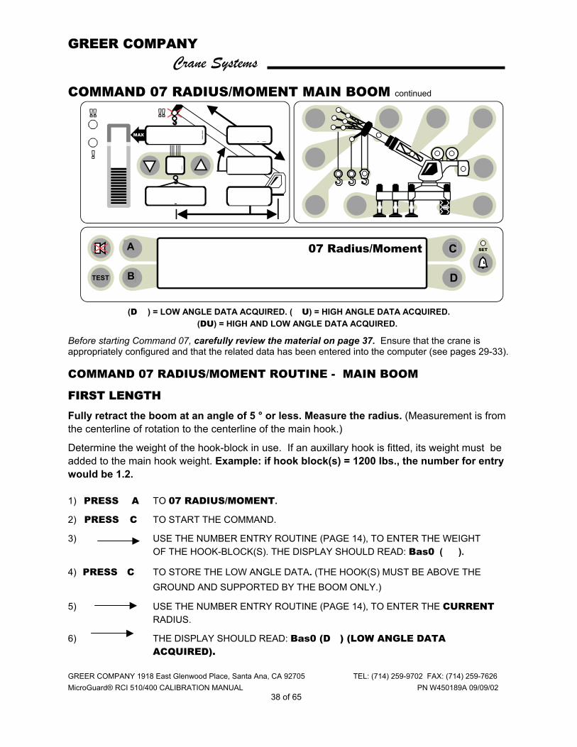
COMMAND 07 RADIUS/MOMENT MAIN BOOM continued
(D ) = LOW ANGLE DATA ACQUIRED. ( U) = HIGH ANGLE DATA ACQUIRED. (DU) = HIGH AND LOW ANGLE DATA ACQUIRED.
Before starting Command 07, carefully review the material on page 37. Ensure that the crane is appropriately configured and that the related data has been entered into the computer (see pages 29-33).
COMMAND 07 RADIUS/MOMENT ROUTINE - MAIN BOOM
FIRST LENGTH
Fully retract the boom at an angle of 5 ° or less. Measure the radius. (Measurement is from the centerline of rotation to the centerline of the main hook.)
Determine the weight of the hook-block in use. If an auxillary hook is fitted, its weight must be added to the main hook weight. Example: if hook block(s) = 1200 lbs., the number for entry would be 1.2. 1) PRESS A TO 07 RADIUS/MOMENT.
2) PRESS C TO START THE COMMAND.
3) USE THE NUMBER ENTRY ROUTINE (PAGE 14), TO ENTER THE WEIGHT OF THE HOOK-BLOCK(S). THE DISPLAY SHOULD READ: Bas0 ( ).
4) PRESS C TO STORE THE LOW ANGLE DATA. (THE HOOK(S) MUST BE ABOVE THE GROUND AND SUPPORTED BY THE BOOM ONLY.)
5) USE THE NUMBER ENTRY ROUTINE (PAGE 14), TO ENTER THE CURRENT RADIUS.
6) THE DISPLAY SHOULD READ: Bas0 (D ) (LOW ANGLE DATA ACQUIRED).
ORs Full 9.7Klb Ctwt ERECTED 60' TELEJIB 17 AUXHD ONPICK FROM MAIN BOOM FRONT WINCH
TEST
MAX
SET 360o
6
23,500
i2,300
44.8
62.7
26.4
o
C A
07 Radius/Moment
B D
C A
GREER COMPANY Crane Systems
GREER COMPANY 1918 East Glenwood Place, Santa Ana, CA 92705 TEL: (714) 259-9702 FAX: (714) 259-7626 MicroGuard® RCI 510/400 CALIBRATION MANUAL PN W450189A 09/09/02
39 of 65
ORs Full 9.7Klb Ctwt ERECTED 60' TELEJIB 17 AUXHD ONPICK FROM MAIN BOOM FRONT WINCH
TEST
MAX
SET 360o
6
23,500
i2,300
44.8
62.7
26.4
o
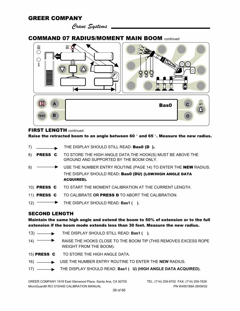
COMMAND 07 RADIUS/MOMENT MAIN BOOM continued
FIRST LENGTH continued Raise the retracted boom to an angle between 60 ° and 65 °. Measure the new radius. 7) THE DISPLAY SHOULD STILL READ: Bas0 (D ).
8) PRESS C TO STORE THE HIGH ANGLE DATA.THE HOOK(S) MUST BE ABOVE THE GROUND AND SUPPORTED BY THE BOOM ONLY.
9) USE THE NUMBER ENTRY ROUTINE (PAGE 14) TO ENTER THE NEW RADIUS. THE DISPLAY SHOULD READ: Bas0 (DU) (LOW/HIGH ANGLE DATA ACQUIRED).
10) PRESS C TO START THE MOMENT CALIBRATION AT THE CURRENT LENGTH.
11) PRESS C TO CALIBRATE OR PRESS D TO ABORT THE CALIBRATION.
12) THE DISPLAY SHOULD READ: Bas1 ( ).
SECOND LENGTH Maintain the same high angle and extend the boom to 50% of extension or to the full extension if the boom mode extends less than 30 feet. Measure the new radius.
13) THE DISPLAY SHOULD STILL READ: Bas1 ( ).
14) RAISE THE HOOKS CLOSE TO THE BOOM TIP (THIS REMOVES EXCESS ROPE WEIGHT FROM THE BOOM).
15) PRESS C TO STORE THE HIGH ANGLE DATA.
16) USE THE NUMBER ENTRY ROUTINE TO ENTER THE NEW RADIUS.
17) THE DISPLAY SHOULD READ: Bas1 ( U) (HIGH ANGLE DATA ACQUIRED).
C
DB
A Bas0
GREER COMPANY Crane Systems
GREER COMPANY 1918 East Glenwood Place, Santa Ana, CA 92705 TEL: (714) 259-9702 FAX: (714) 259-7626 MicroGuard® RCI 510/400 CALIBRATION MANUAL PN W450189A 09/09/02
40 of 65
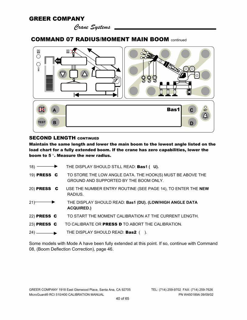
COMMAND 07 RADIUS/MOMENT MAIN BOOM continued
SECOND LENGTH CONTINUED
Maintain the same length and lower the main boom to the lowest angle listed on the load chart for a fully extended boom. If the crane has zero capabilities, lower the boom to 5 °. Measure the new radius. 18) THE DISPLAY SHOULD STILL READ: Bas1 ( U).
19) PRESS C TO STORE THE LOW ANGLE DATA. THE HOOK(S) MUST BE ABOVE THE GROUND AND SUPPORTED BY THE BOOM ONLY.
20) PRESS C USE THE NUMBER ENTRY ROUTINE (SEE PAGE 14), TO ENTER THE NEW RADIUS.
21) THE DISPLAY SHOULD READ: Bas1 (DU). (LOW/HIGH ANGLE DATA ACQUIRED.)
22) PRESS C TO START THE MOMENT CALIBRATION AT THE CURRENT LENGTH.
23) PRESS C TO CALIBRATE OR PRESS D TO ABORT THE CALIBRATION.
24) THE DISPLAY SHOULD READ: Bas2 ( ). Some models with Mode A have been fully extended at this point. If so, continue with Command 08, (Boom Deflection Correction), page 46.
ORs Full 9.7Klb Ctwt ERECTED 60' TELEJIB 17 AUXHD ONPICK FROM MAIN BOOM FRONT WINCH
TEST
MAX
SET 360o
6
23,500
i2,300
44.8
62.7
26.4
oC
DB
A Bas1
B D
C A
GREER COMPANY Crane Systems
GREER COMPANY 1918 East Glenwood Place, Santa Ana, CA 92705 TEL: (714) 259-9702 FAX: (714) 259-7626 MicroGuard® RCI 510/400 CALIBRATION MANUAL PN W450189A 09/09/02
41 of 65
COMMAND 07 RADIUS/MOMENT MAIN BOOM continued
THIRD LENGTH MAINTAIN THE SAME LOW ANGLE AND FULLY EXTEND THE MAIN BOOM. MEASURE THE NEW RADIUS.
25) THE DISPLAY SHOULD STILL READ: Bas2 ( ).
26) PRESS C TO STORE THE LOW ANGLE DATA. THE HOOK(S) MUST BE ABOVE THE GROUND AND SUPPORTED BY THE BOOM ONLY.
27) USE THE NUMBER ENTRY ROUTINE (PAGE 14) TO ENTER THE NEW RADIUS.
28) THE DISPLAY SHOULD READ: Bas2 (D ) (LOW ANGLE DATA ACQUIRED).
29) PRESS C TO START THE CALIBRATION AT THE CURRENT LENGTH.
30) PRESS C TO CALIBRATE OR PRESS D TO ABORT THE CALIBRATION.
THIRD LENGTH CONTINUED
RAISE THE FULLY EXTENDED BOOM TO AN ANGLE BETWEEN 60 ° AND 65 °. MEASURE THE NEW RADIUS.
31) THE DISPLAY SHOULD STILL READ: Bas2 (D ).
32) PRESS C TO STORE THE HIGH ANGLE DATA. THE HOOK(S) MUST BE ABOVE THE GROUND AND SUPPORTED BY THE BOOM ONLY.
33) USE THE NUMBER ENTRY ROUTINE (PAGE 14), TO ENTER THE NEW RADIUS.
34) THE DISPLAY SHOULD READ: Bas2 (DU) (LOW/HIGH ANGLE DATA ACQUIRED).
35) PRESS C TO START THE MOMENT CALIBRATION AT THE CURRENT LENGTH.
36) PRESS C TO CALIBRATE OR PRESS D TO ABORT THE CALIBRATION.
37) PRESS D TO EXIT THE ROUTINE.
CARRY OUT COMMAND 08 BDC PRIOR TO DOING THE MAIN BOOM + MANUAL RADIUS AND MOMENT CALIBRATION. IF THERE IS A MANUAL SECTION OR MODE B EQUIPPED ON THE CRANE, RETURN TO COMMAND 07 AFTER COMPLETING THE BDC FOR THE MAIN BOOM.

GREER COMPANY Crane Systems
GREER COMPANY 1918 East Glenwood Place, Santa Ana, CA 92705 TEL: (714) 259-9702 FAX: (714) 259-7626 MicroGuard® RCI 510/400 CALIBRATION MANUAL PN W450189A 09/09/02
42 of 65
COMMAND 07 RADIUS/MOMENT MAIN BOOM + MANUAL
MAIN BOOM + MANUAL
♦ EXIT THE CALIBRATION MODE.
♦ SELECT MAIN BOOM + MANUAL. SEE CRANE SET-UP (NORMAL WORKING SCREEN).
♦ EXTEND THE MANUAL SECTION.
♦ FULLY RETRACT THE BOOM AT 5°.
♦ DETERMINE THE WEIGHT OF THE HOOK-BLOCK IN USE.
♦ RAISE THE HOOK-BLOCK TO ELIMINATE ROPE WEIGHT.
♦ CALIBRATE THE RADIUS AND MOMENT OF THE MAIN BOOM + MANUAL (NEXT PAGE).
GREER COMPANY Crane Systems
GREER COMPANY 1918 East Glenwood Place, Santa Ana, CA 92705 TEL: (714) 259-9702 FAX: (714) 259-7626 MicroGuard® RCI 510/400 CALIBRATION MANUAL PN W450189A 09/09/02
43 of 65
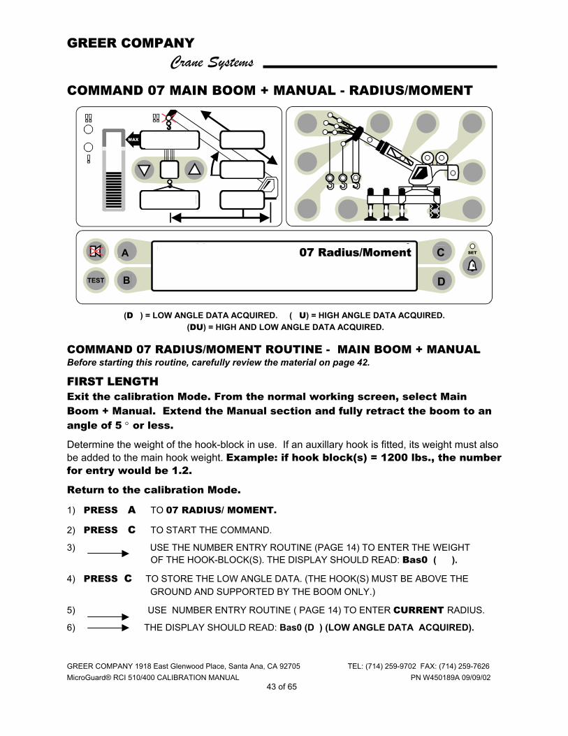
COMMAND 07 MAIN BOOM + MANUAL - RADIUS/MOMENT
(D ) = LOW ANGLE DATA ACQUIRED. ( U) = HIGH ANGLE DATA ACQUIRED. (DU) = HIGH AND LOW ANGLE DATA ACQUIRED.
COMMAND 07 RADIUS/MOMENT ROUTINE - MAIN BOOM + MANUAL Before starting this routine, carefully review the material on page 42.
FIRST LENGTH Exit the calibration Mode. From the normal working screen, select Main Boom + Manual. Extend the Manual section and fully retract the boom to an angle of 5 ° or less.
Determine the weight of the hook-block in use. If an auxillary hook is fitted, its weight must also be added to the main hook weight. Example: if hook block(s) = 1200 lbs., the number for entry would be 1.2.
Return to the calibration Mode.
1) PRESS A TO 07 RADIUS/ MOMENT.
2) PRESS C TO START THE COMMAND.
3) USE THE NUMBER ENTRY ROUTINE (PAGE 14) TO ENTER THE WEIGHT OF THE HOOK-BLOCK(S). THE DISPLAY SHOULD READ: Bas0 ( ).
4) PRESS C TO STORE THE LOW ANGLE DATA. (THE HOOK(S) MUST BE ABOVE THE GROUND AND SUPPORTED BY THE BOOM ONLY.)
5) USE NUMBER ENTRY ROUTINE ( PAGE 14) TO ENTER CURRENT RADIUS.
6) THE DISPLAY SHOULD READ: Bas0 (D ) (LOW ANGLE DATA ACQUIRED).
ORs Full 9.7Klb Ctwt ERECTED 60' TELEJIB 17 AUXHD ONPICK FROM MAIN BOOM FRONT WINCH
TEST
MAX
SET 360o
6
23,500
i2,300
44.8
62.7
26.4
o07 Radius/Moment
B D
C A

GREER COMPANY Crane Systems
GREER COMPANY 1918 East Glenwood Place, Santa Ana, CA 92705 TEL: (714) 259-9702 FAX: (714) 259-7626 MicroGuard® RCI 510/400 CALIBRATION MANUAL PN W450189A 09/09/02
44 of 65
COMMAND 07 MAIN BOOM - RADIUS/MOMENT MAIN BOOM + MANUAL continued
FIRST LENGTH continued
Raise the retracted boom to an angle between 60 ° and 65 °. Measure the new radius. 7) THE DISPLAY SHOULD STILL READ: Bas0(D ).
8) PRESS C TO STORE THE HIGH ANGLE DATA. THE HOOK(S) MUST BE ABOVE THE GROUND AND SUPPORTED BY THE BOOM ONLY.
9) USE THE NUMBER ENTRY ROUTINE (PAGE 14) TO ENTER THE NEW RADIUS. THE DISPLAY SHOULD READ: Bas0 (DU) (LOW/HIGH ANGLE DATA ACQUIRED).
10) PRESS C TO START THE MOMENT CALIBRATION AT THE CURRENT LENGTH.
11) PRESS C TO CALIBRATE OR PRESS D TO ABORT THE CALIBRATION.
12) THE DISPLAY SHOULD READ: Bas1 ( ). . SECOND LENGTH Maintain the same high angle and extend the boom to 50% of boom extension. Measure the new radius.
13) THE DISPLAY SHOULD STILL READ: Bas1 ( ).
14) RAISE THE HOOKS CLOSE TO THE BOOM TIP (THIS REMOVES EXCESS ROPE WEIGHT FROM THE BOOM).
15) PRESS C TO STORE THE HIGH ANGLE DATA
16) USE THE NUMBER ENTRY ROUTINE (PAGE 14) TO ENTER THE NEW RADIUS.
!7) THE DISPLAY SHOULD READ: Bas1( U) (HIGH ANGLE DATA ACQUIRED).
SECOND LENGTH continued Maintain the same length and lower the boom to 5 °. Measure the new radius. 18) THE DISPLAY SHOULD STILL READ: Bas1 ( U).
19) PRESS C TO STORE THE LOW ANGLE DATA. THE HOOK(S) MUST BE ABOVE THE GROUND AND SUPPORTED BY THE BOOM ONLY.
20) USE THE NUMBER ENTRY ROUTINE TO ENTER THE NEW RADIUS. 21) THE DISPLAY SHOULD READ: Bas1 (DU). (LOW/HIGH ANGLE DATA
ACQUIRED).

GREER COMPANY Crane Systems
GREER COMPANY 1918 East Glenwood Place, Santa Ana, CA 92705 TEL: (714) 259-9702 FAX: (714) 259-7626 MicroGuard® RCI 510/400 CALIBRATION MANUAL PN W450189A 09/09/02
45 of 65
COMMAND 07 MAIN BOOM + MANUAL RADIUS/MOMENT
MAIN BOOM + MANUAL ROUTINE - SECOND LENGTH continued
22) PRESS C TO START THE MOMENT CALIBRATION AT THE CURRENT LENGTH. 23) PRESS C TO CALIBRATE OR PRESS D TO ABORT THE CALIBRATION.
24) THE DISPLAY SHOULD READ: Bas2 ( ). Some models with Mode A have been fully extended at this point. If so, continue with Command 08 (Boom Deflection Correction) on page 46.
THIRD LENGTH Maintain the same low angle and fully extend the boom. Measure the new radius. 25) THE DISPLAY SHOULD STILL READ Bas2 ( ).
26) PRESS C TO STORE THE LOW ANGLE DATA. THE HOOKS MUST BE ABOVE THE GROUND AND SUPPORTED BY THE BOOM ONLY.
27) USING THE NUMBER ENTRY ROUTINE, ENTER THE NEW RADIUS.
28) THE DISPLAY SHOULD READ: Bas2 (D ) LOW ANGLE DATA ACQUIRED.
29) PRESS C TO START THE MOMENT CALIBRATION AT THE CURRENT LENGTH.
30) PRESS C TO CALIBRATE OR PRESS D TO ABORT THE CALIBRATION.
THIRD LENGTH CONTINUED Raise the fully extended boom to an angle between 60 ° and 65 °. Measure the new radius.
31) THE DISPLAY SHOULD STILL READ: Bas2 (D )
32) PRESS C TO STORE THE HIGH ANGLE DATA. THE HOOKS MUST BE ABOVE THE GROUND AND SUPPORTED BY THE BOOM ONLY.
33) USING THE NUMBER ENTRY ROUTINE, ENTER THE NEW RADIUS.
34) THE DISPLAY SHOULD READ: Bas2 (DU). (HIGH AND LOW ANGLE DATA ACQUIRED)
35) PRESS C TO START THE MOMENT CALIBRATION AT THE CURRENT LENGTH.
36) PRESS C TO CALIBRATE OR PRESS D TO ABORT THE CALIBRATION.
37) PRESS D AFTER THE MESSAGE, ‘CALIBRATING’ ENDS, TO EXIT THE ROUTINE.
GREER COMPANY Crane Systems
GREER COMPANY 1918 East Glenwood Place, Santa Ana, CA 92705 TEL: (714) 259-9702 FAX: (714) 259-7626 MicroGuard® RCI 500 CALIBRATION PROCEDURE PN W450189A 09/09/02
46 of 65
COMMAND 08 BOOM DEFLECTION CORRECTION (BDC)
♦ With the boom fully extended at an angle of approximately 65°, pick up the maximum permitted load.
♦ Measure the deflected radius and add 0.2' to the measured radius. The radius is measured
from the centerline of rotation to the center of the load. With the load still suspended, calibrate the bdc as follows: IF THE RADIUS IS ALREADY CORRECT, SKIP THIS PROCEDURE. 1) PRESS A TO 08 BOOM DEFLECTION.
2) PRESS C TO START THE COMMAND.
3) PRESS C TO START THE BDC CALIBRATION.
4) PRESS C TO CALIBRATE OR PRESS D TO ABORT THE CALIBRATION.
5) USING THE NUMBER ENTRY ROUTINE, ENTER THE NEW RADIUS.
6) PRESS D TO EXIT THE ROUTINE.
”Ofld ang” ON THE DISPLAY SCREEN = OFFLOAD ANGLE.
”Onld ang” ON THE DISPLAY SCREEN = ONLOAD ANGLE.
Any attempt to enter data outside of the above limits will result in the warning message, ”poor angle. ”
• When the message ”poor angle” occurs as the result of an error, Press D (bad angle) to abort the entry. Continue the procedure using correct keyboard entries.
• When the message ”poor angle” occurs as a result of entering data outside of the preferred angles, Press C (angle ok) to approve the out of range angle data.
• If the angle is not accepted by the system, the operator must abort or accept it. If accepted, the boom must be adjusted to the appropriate angle.
• If this procedure has just been carried out on the main boom, continue with main boom + manual radius and moment, Command 07.

GREER COMPANY Crane Systems
GREER COMPANY 1918 East Glenwood Place, Santa Ana, CA 92705 TEL: (714) 259-9702 FAX: (714) 259-7626 MicroGuard® RCI 510/400 CALIBRATION MANUAL PN W450189A 09/09/02
47 of 65
COMMAND 09 ANNULAR GAIN There are two pressure transducers fitted in the system. One measures piston side pressure and the other measures rod side pressure.
Because these are not identical cross-sectional areas, data must be entered that define the ratio of the two areas. This ratio is referred to as annular gain (a.g.). Annular gain is calculated from the rod (r) and bore (b) diameters as follows:
A.G. = [(RXR)/(BXB)] - 1 E.G. R = 8 AND B = 10 A.G. = - 0.360
♦ Although the annular gain value is automatically entered at the time of initialization,
modification of this value may be required due to differing pressure transducer sensitivities. ♦ If the load reading changes significantly when booming down, the annular gain should be
changed. TO CHANGE THE SETTING OF THE ANNULAR GAIN: 1) PRESS A TO 09 ANNULAR GAIN. 2) PRESS C TO START THE COMMAND.
IF THE LOAD DECREASES WHEN BOOMING DOWN, PRESS THE UP ANNULAR GAIN KEY (A).
IF THE LOAD INCREASES WHEN BOOMING DOWN, PRESS THE DOWN ANNULAR GAIN KEY (B).
3) PRESS C TO START THE ANNULAR GAIN CALIBRATION.
4) PRESS C TO CALIBRATE OR PRESS D TO ABORT THE CALIBRATION.
5) PRESS D TO EXIT THE ROUTINE.
GREER COMPANY Crane Systems
GREER COMPANY 1918 East Glenwood Place, Santa Ana, CA 92705 TEL: (714) 259-9702 FAX: (714) 259-7626 MicroGuard® RCI 510/400 CALIBRATION MANUAL PN W450189A 09/09/02
48 of 65
COMMAND 12 WINCHES Command 12 permits "hiding" a winch that is not in use or "activating" a winch that is hidden. Winches are classified as “active” or “hidden.” Watch the display screen showing the two winches. After completing the routine below, a green light will flash above the active winch. TO HIDE OR ACTIVATE A WINCH: 1) PRESS A TO 12 WINCHES.
2) PRESS C TO START THE COMMAND.
3) PRESS B TO TOGGLE BETWEEN THE TWO WINCHES.
4) PRESS C TO CHANGE FROM ‘SELECTABLE’ TO ‘HIDDEN’ (OR VICE VERSA).
5) PRESS C TO CALIBRATE OR PRESS D TO ABORT THE CALIBRATION.
6) PRESS D TO EXIT THE ROUTINE. COMMAND 13 ATTACHMENTS
Command 13 permits ”hiding” an attachment not in use or returning a hidden attachment to a ”selectable” (active) status.
1) PRESS A TO COMMAND 13 ATTACHMENTS.
2) PRESS C TO START THE COMMAND.
3) PRESS B TO THE ATTACHMENT TO BE CHANGED.
4) PRESS C TO CHANGE FROM ‘SELECTABLE’ TO ‘HIDDEN’ OR VICE VERSA.
5) PRESS C TO CALIBRATE OR PRESS D TO ABORT CALIBRATION.
6) PRESS D TO EXIT THE ROUTINE.

GREER COMPANY Crane Systems
GREER COMPANY 1918 East Glenwood Place, Santa Ana, CA 92705 TEL: (714) 259-9702 FAX: (714) 259-7626 MicroGuard® RCI 500 CALIBRATION PROCEDURE PN W450189A 09/09/02
49 of 65
COMMAND 14 BOOM HEAD
Command 14 boom head relates to the length and angle of the boom.
There are seven (0-6) possible entries for the length of varying boom segments. After len.0, Press A to the next length(s). Press B to previous length(s).
When the length entry calibration is completed, Press D to the boom angle data entry section. There are seven (0-6) categories for angle data corresponding to each entry for boom length. Proceed as usual following the routine on the next page.
GREER COMPANY Crane Systems
GREER COMPANY 1918 East Glenwood Place, Santa Ana, CA 92705 TEL: (714) 259-9702 FAX: (714) 259-7626 MicroGuard® RCI 510/400 CALIBRATION MANUAL PN W450189A 09/09/02
50 of 65
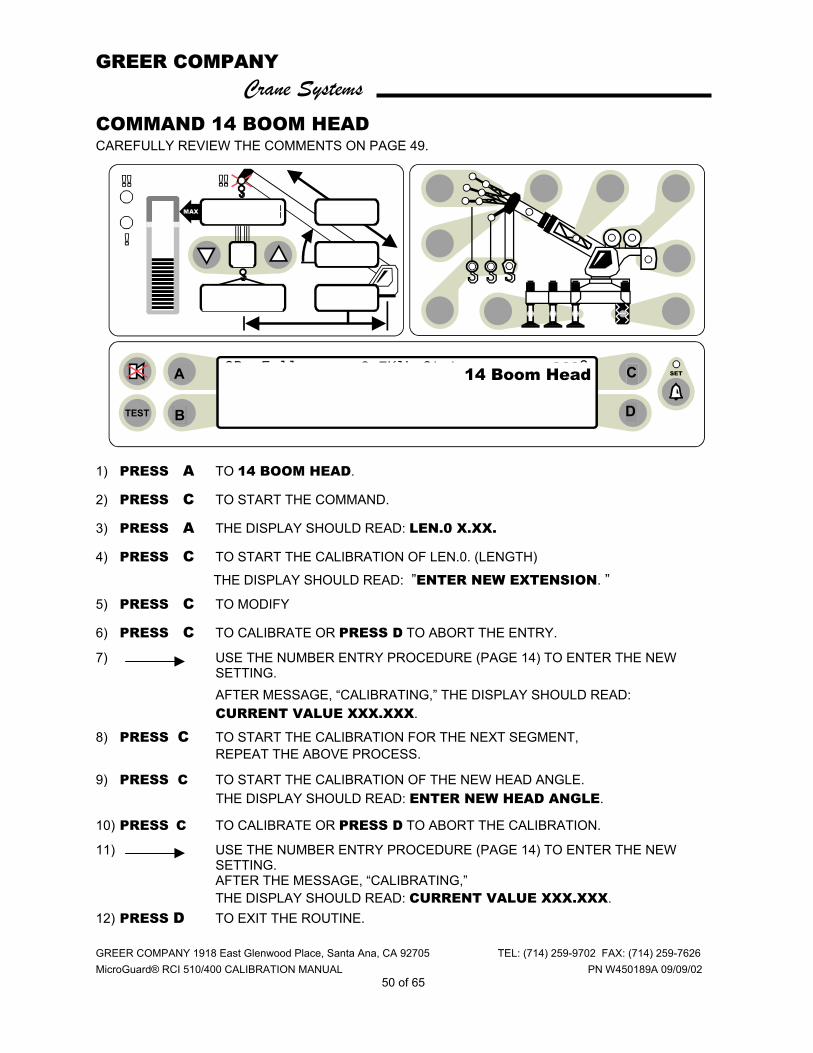
COMMAND 14 BOOM HEAD CAREFULLY REVIEW THE COMMENTS ON PAGE 49.
1) PRESS A TO 14 BOOM HEAD.
2) PRESS C TO START THE COMMAND.
3) PRESS A THE DISPLAY SHOULD READ: LEN.0 X.XX.
4) PRESS C TO START THE CALIBRATION OF LEN.0. (LENGTH)
THE DISPLAY SHOULD READ: ”ENTER NEW EXTENSION. ” 5) PRESS C TO MODIFY
6) PRESS C TO CALIBRATE OR PRESS D TO ABORT THE ENTRY.
7) USE THE NUMBER ENTRY PROCEDURE (PAGE 14) TO ENTER THE NEW SETTING. AFTER MESSAGE, “CALIBRATING,” THE DISPLAY SHOULD READ: CURRENT VALUE XXX.XXX.
8) PRESS C TO START THE CALIBRATION FOR THE NEXT SEGMENT, REPEAT THE ABOVE PROCESS.
9) PRESS C TO START THE CALIBRATION OF THE NEW HEAD ANGLE. THE DISPLAY SHOULD READ: ENTER NEW HEAD ANGLE.
10) PRESS C TO CALIBRATE OR PRESS D TO ABORT THE CALIBRATION.
11) USE THE NUMBER ENTRY PROCEDURE (PAGE 14) TO ENTER THE NEW SETTING. AFTER THE MESSAGE, “CALIBRATING,” THE DISPLAY SHOULD READ: CURRENT VALUE XXX.XXX.
12) PRESS D TO EXIT THE ROUTINE.
ORs Full 9.7Klb Ctwt ERECTED 60' TELEJIB 17 AUXHD ONPICK FROM MAIN BOOM FRONT WINCH
TEST
MAX
SET 360o
6
23,500
i2,300
44.8
62.7
26.4
o14 Boom Head
B D
C A

GREER COMPANY Crane Systems
GREER COMPANY 1918 East Glenwood Place, Santa Ana, CA 92705 TEL: (714) 259-9702 FAX: (714) 259-7626 MicroGuard® RCI 510/400 CALIBRATION MANUAL PN W450189A 09/09/02
51 of 65
COMMAND 15 ALARM LIMITS
At the initialization of the system the following values are set. ♦ ALARM 0 100% SWL RED LAMP AND MOTION-CUT RELAY ♦ ALARM 1 90% SWL AMBER LAMP AND PRE-ALARM RELAY ♦ ALARM 2 90% SWL INTERNAL AUDIBLE ALARM The alarm command may be modified. Entry should be as percentages using decimals. Follow the routine on the next page.
GREER COMPANY Crane Systems
GREER COMPANY 1918 East Glenwood Place, Santa Ana, CA 92705 TEL: (714) 259-9702 FAX: (714) 259-7626 MicroGuard® RCI 510/400 CALIBRATION MANUAL PN W450189A 09/09/02
52 of 65
COMMAND 15 ALARM LIMITS continued
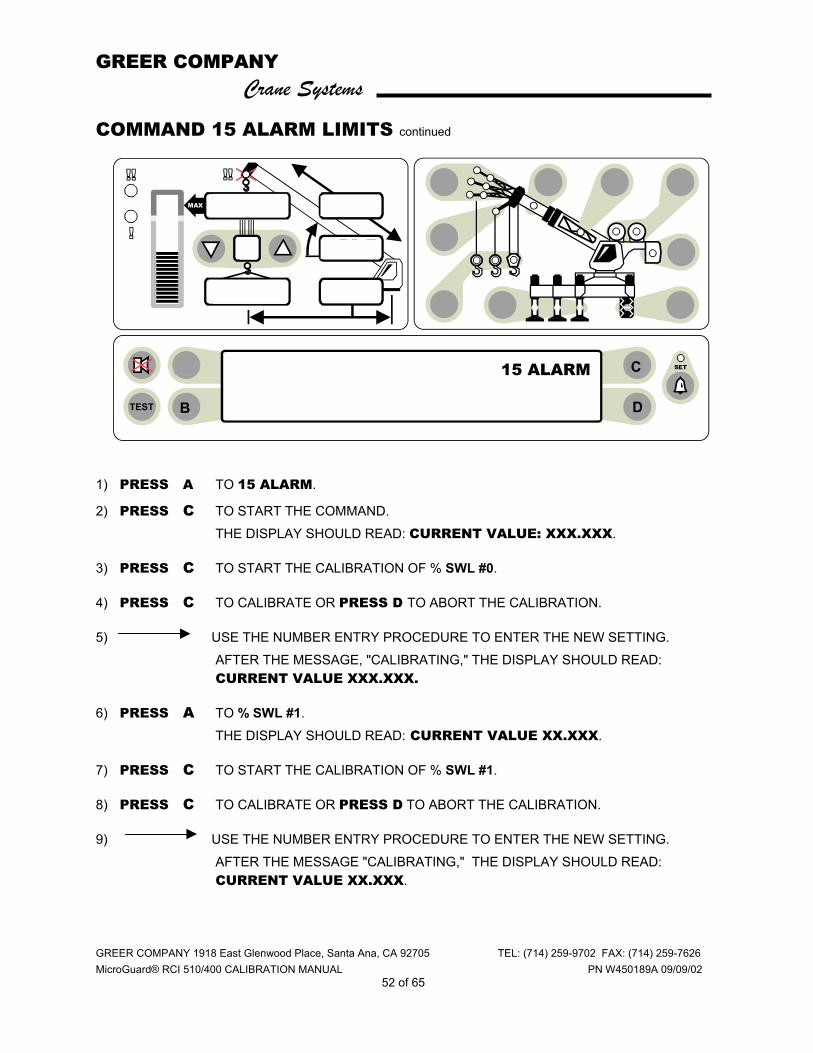
1) PRESS A TO 15 ALARM.
2) PRESS C TO START THE COMMAND. THE DISPLAY SHOULD READ: CURRENT VALUE: XXX.XXX.
3) PRESS C TO START THE CALIBRATION OF % SWL #0.
4) PRESS C TO CALIBRATE OR PRESS D TO ABORT THE CALIBRATION.
5) USE THE NUMBER ENTRY PROCEDURE TO ENTER THE NEW SETTING. AFTER THE MESSAGE, "CALIBRATING," THE DISPLAY SHOULD READ: CURRENT VALUE XXX.XXX.
6) PRESS A TO % SWL #1. THE DISPLAY SHOULD READ: CURRENT VALUE XX.XXX.
7) PRESS C TO START THE CALIBRATION OF % SWL #1.
8) PRESS C TO CALIBRATE OR PRESS D TO ABORT THE CALIBRATION.
9) USE THE NUMBER ENTRY PROCEDURE TO ENTER THE NEW SETTING. AFTER THE MESSAGE "CALIBRATING," THE DISPLAY SHOULD READ: CURRENT VALUE XX.XXX.
ORs Full 9.7Klb Ctwt ERECTED 60' TELEJIB 17 AUXHD ONPICK FROM MAIN BOOM FRONT WINCH
TEST
MAX
SET 360o
6
23,500
i2,300
44.8
62.7
26.4
o C
D B
15 ALARM
GREER COMPANY Crane Systems
GREER COMPANY 1918 East Glenwood Place, Santa Ana, CA 92705 TEL: (714) 259-9702 FAX: (714) 259-7626 MicroGuard® RCI 510/400 CALIBRATION MANUAL PN W450189A 09/09/02
53 of 65
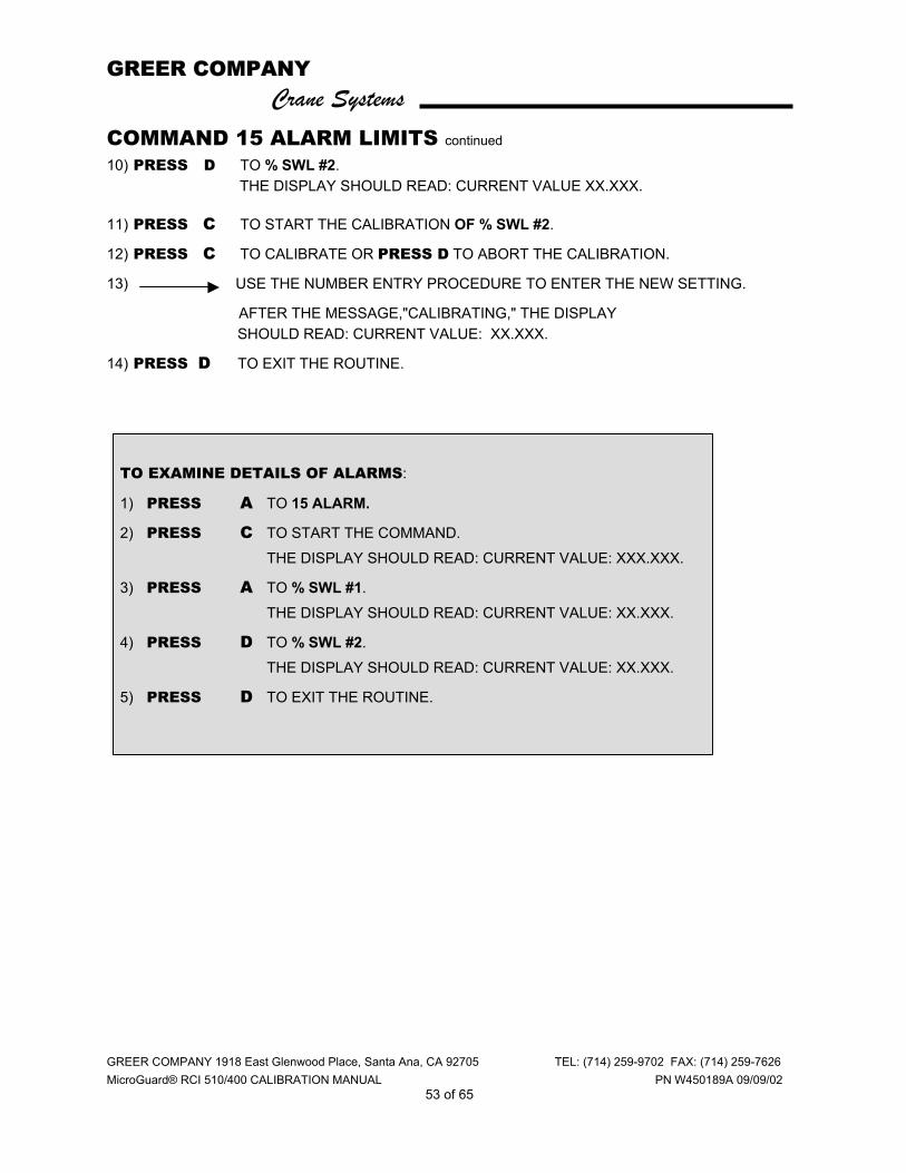
COMMAND 15 ALARM LIMITS continued 10) PRESS D TO % SWL #2.
THE DISPLAY SHOULD READ: CURRENT VALUE XX.XXX.
11) PRESS C TO START THE CALIBRATION OF % SWL #2.
12) PRESS C TO CALIBRATE OR PRESS D TO ABORT THE CALIBRATION.
13) USE THE NUMBER ENTRY PROCEDURE TO ENTER THE NEW SETTING.
AFTER THE MESSAGE,"CALIBRATING," THE DISPLAY SHOULD READ: CURRENT VALUE: XX.XXX.
14) PRESS D TO EXIT THE ROUTINE.
TO EXAMINE DETAILS OF ALARMS:
1) PRESS A TO 15 ALARM.
2) PRESS C TO START THE COMMAND. THE DISPLAY SHOULD READ: CURRENT VALUE: XXX.XXX.
3) PRESS A TO % SWL #1. THE DISPLAY SHOULD READ: CURRENT VALUE: XX.XXX.
4) PRESS D TO % SWL #2. THE DISPLAY SHOULD READ: CURRENT VALUE: XX.XXX.
5) PRESS D TO EXIT THE ROUTINE.

GREER COMPANY Crane Systems
GREER COMPANY 1918 East Glenwood Place, Santa Ana, CA 92705 TEL: (714) 259-9702 FAX: (714) 259-7626 MicroGuard® RCI 510/400 CALIBRATION MANUAL PN W450189A 09/09/02
54 of 65
COMMAND 16 ROPE DATA
♦ Maximum hoist rope tension is specified by the crane manufacturer for the size and type of wire rope used on the crane. This value is set at the initialization of the system.
♦ The rope data command permits the modification of these values, which should be entered in units of 1000 #. Example 11,700 # is entered as 11.70
To change this data, continue with the routine on the next page.
GREER COMPANY Crane Systems
GREER COMPANY 1918 East Glenwood Place, Santa Ana, CA 92705 TEL: (714) 259-9702 FAX: (714) 259-7626 MicroGuard® RCI 510/400 CALIBRATION MANUAL PN W450189A 09/09/02
55 of 65
COMMAND 16 ROPE DATA continued
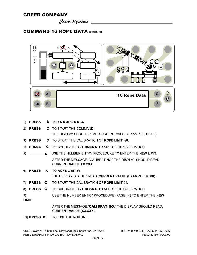
1) PRESS A TO 16 ROPE DATA.
2) PRESS C TO START THE COMMAND. THE DISPLAY SHOULD READ: CURRENT VALUE (EXAMPLE: 12.000).
3) PRESS C TO START THE CALIBRATION OF ROPE LIMIT #0.
4) PRESS C TO CALIBRATE OR PRESS D TO ABORT THE CALIBRATION.
5) USE THE NUMBER ENTRY PROCEDURE TO ENTER THE NEW LIMIT.
AFTER THE MESSAGE, “CALIBRATING,” THE DISPLAY SHOULD READ: CURRENT VALUE XX.XXX.
6) PRESS A TO ROPE LIMIT #1. THE DISPLAY SHOULD READ: CURRENT VALUE (EXAMPLE: 9.080).
7) PRESS C TO START THE CALIBRATION OF ROPE LIMIT #1.
8) PRESS C TO CALIBRATE OR PRESS D TO ABORT THE CALIBRATION.
9) USE THE NUMBER ENTRY PROCEDURE (PAGE 14) TO ENTER THE NEW LIMIT.
AFTER THE MESSAGE,"CALIBRATING," THE DISPLAY SHOULD READ: CURRENT VALUE (XX.XXX).
10) PRESS D TO EXIT THE ROUTINE.
ORs Full 9.7Klb Ctwt ERECTED 60' TELEJIB 17 AUXHD ONPICK FROM MAIN BOOM FRONT WINCH
TEST
MAX
SET 360o
6
23,500
i2,300
44.8
62.7
26.4
o
B D
C A 16 Rope Data
GREER COMPANY Crane Systems
GREER COMPANY 1918 East Glenwood Place, Santa Ana, CA 92705 TEL: (714) 259-9702 FAX: (714) 259-7626 MicroGuard® RCI 510/400 CALIBRATION MANUAL PN W450189A 09/09/02
56 of 65
COMMAND 16 ROPE DATA continued TO EXAMINE THE DETAILS OF ROPE DATA:
1) PRESS A TO 16 ROPE DATA.
2) PRESS C TO START THE COMMAND. THE DISPLAY SHOULD READ: CURRENT VALUE: 12.000 (EXAMPLE).
3) PRESS D TO ROPE LIMIT #1. THE DISPLAY SHOULD READ: CURRENT VALUE 9.080 (EXAMPLE).
4) PRESS D TO EXIT THE ROUTINE.
GREER COMPANY Crane Systems
GREER COMPANY 1918 East Glenwood Place, Santa Ana, CA 92705 TEL: (714) 259-9702 FAX: (714) 259-7626 MicroGuard® RCI 510/400 CALIBRATION MANUAL PN W450189A 09/09/02
57 of 65
COMMAND 17 AMPLIFIER GAIN
At the time of initialization the amplifier gain is set to the preferred value of 2. This value is suitable for the standard load cells and pressure transducers supplied with the systems. This gain setting may be modified, as necessary, for special application, using the following routine.
Confer with the factory before making any changes.
1) PRESS A TO 17 AMPLIFIER.
2) PRESS C TO START THE COMMAND. THE DISPLAY WILL READ THE CURRENT VALUE.
3) PRESS C TO START THE CALIBRATION OFAMPLIFIER GAIN.
4) PRESS C TO CALIBRATE OR PRESS D TO ABORT CALIBRATION OF ABOVE DATA.
5) PRESS B TO CHANGE THE SETTING.
6) PRESS C TO COMPLETE THE CALIBRATION.
7) PRESS C TO EXIT THE ROUTINE. COMMAND 01/3 BACK-UP After completing a calibration routine and after executing command 01/0 save, use the following procedure to obtain a permanent copy of the calibration.
1) PRESS A TO 01 PERSONALITY.
2) PRESS C TO START THE COMMAND.
3) PRESS A TO 3 BACKUP A TO RAM.
4) PRESS C TO START THE COMMAND.
5) PRESS C TO CALIBRATE OR PRESS D TO ABORT THE CALIBRATION OF ABOVE DATA.
6) PRESS 1234 (CALIBRATION CODE)
7) PRESS D AFTER THE MESSAGE,"CALIBRATING" TO EXIT THE ROUTINE. SWITCH OFF POWER TO THE SYSTEM
GREER COMPANY Crane Systems
GREER COMPANY 1918 East Glenwood Place, Santa Ana, CA 92705 TEL: (714) 259-9702 FAX: (714) 259-7626 MicroGuard® RCI 510/400 CALIBRATION MANUAL PN W450189A 09/09/02
58 of 65
SWITCH OFF POWER TO THE SYSTEM BEFORE REMOVING OR INSERTING INTEGRATED CIRCUITS.
A copy of the contents of the "A" portion of the “Personality” is now stored temporarily in memory in the computer. The chip in socket ic7 is removed and will be the service back-up chip. To reinstate the system to working condition, fit a new chip, type 28c65, in socket IC7. Restore power to the system and carry out Command 01/4-restore as follows:
RESTORE POWER AND ENTER THE CALIBRATION ROUTINE
1) PRESS AND HOLD THE TEST AND SET KEYS FOR APPROXIMATELY 10 SECONDS.
2) PRESS 1234 (CALIBRATION ENTRY CODE).
3) PRESS C TO CALIBRATE OR PRESS D TO ABORT THE CALIBRATION.
COMMAND 01/4 RESTORE
1) PRESS A TO 01 PERSONALITY.
2) PRESS C TO START THE COMMAND.
3) PRESS A TO 01/4 RESTORE.
4) PRESS C TO START THE COMMAND.
5) PRESS C TO CALIBRATE OR PRESS D TO ABORT THE CALIBRATION.
6) PRESS 1234 (CALIBRATION ENTRY CODE).
7) PRESS D AFTER THE MESSAGE,” CALIBRATING” TO EXIT. THE COPY OF THE CALIBRATION PERSONALITY IS NOW RESTORED TO THE "A" SECTION OF IC7. SAVE IT NOW TO THE "B" SECTION USING COMMAND 1/0 SAVE.

GREER COMPANY Crane Systems
GREER COMPANY 1918 East Glenwood Place, Santa Ana, CA 92705 TEL: (714) 259-9702 FAX: (714) 259-7626 MicroGuard® RCI 510/400 CALIBRATION MANUAL PN W450189A 09/09/02
59 of 65
COMMAND 19 DIGITAL INPUTS The logic status of digital inputs is displayed using Command 19. The inputs can be high or low. Low is indicated by 0 and high is indicated by 1. 1) PRESS A TO 19 DIGITAL INPUTS.
2) PRESS C TO START THE COMMAND. THE DISPLAY SHOULD READ THE STATUS OF ALL DIGITAL INPUTS.
3) PRESS D TO EXIT THE ROUTINE. DIGITAL INPUTS
0 OPTINAL SWING INPUT
1 OPTINAL SWING INPUT
2 OPTINAL SWING INPUT
3 OPTINAL SWING INPUT
4 OPTINAL SWING INPUT
5 OPTINAL SWING INPUT
6 OPTINAL SWING INPUT
7 OPTINAL SWING INPUT
8 NOT USED
9 NOT USED
A BY-PASS MESSAGE HI = NO MESSAGE
B SELECT OPTIONAL CHART HI = SELECT CHART
C NOT USED
D ATB IN HI = NO ALARM
E NOT USED
F NOT USED
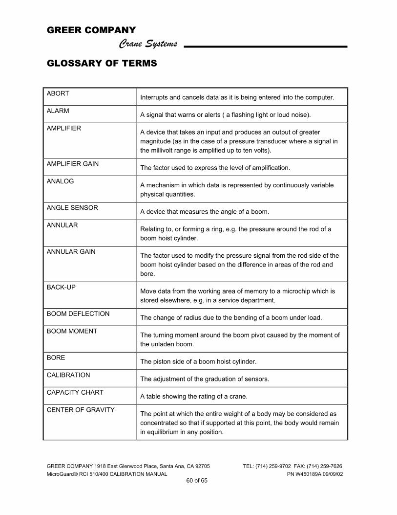
GREER COMPANY Crane Systems
GREER COMPANY 1918 East Glenwood Place, Santa Ana, CA 92705 TEL: (714) 259-9702 FAX: (714) 259-7626 MicroGuard® RCI 510/400 CALIBRATION MANUAL PN W450189A 09/09/02
60 of 65
GLOSSARY OF TERMS ABORT Interrupts and cancels data as it is being entered into the computer.
ALARM A signal that warns or alerts ( a flashing light or loud noise).
AMPLIFIER A device that takes an input and produces an output of greater magnitude (as in the case of a pressure transducer where a signal in the millivolt range is amplified up to ten volts).
AMPLIFIER GAIN The factor used to express the level of amplification.
ANALOG A mechanism in which data is represented by continuously variable physical quantities.
ANGLE SENSOR A device that measures the angle of a boom.
ANNULAR Relating to, or forming a ring, e.g. the pressure around the rod of a boom hoist cylinder.
ANNULAR GAIN The factor used to modify the pressure signal from the rod side of the boom hoist cylinder based on the difference in areas of the rod and bore.
BACK-UP Move data from the working area of memory to a microchip which is stored elsewhere, e.g. in a service department.
BOOM DEFLECTION The change of radius due to the bending of a boom under load.
BOOM MOMENT The turning moment around the boom pivot caused by the moment of the unladen boom.
BORE The piston side of a boom hoist cylinder.
CALIBRATION The adjustment of the graduation of sensors.
CAPACITY CHART A table showing the rating of a crane.
CENTER OF GRAVITY The point at which the entire weight of a body may be considered as concentrated so that if supported at this point, the body would remain in equilibrium in any position.
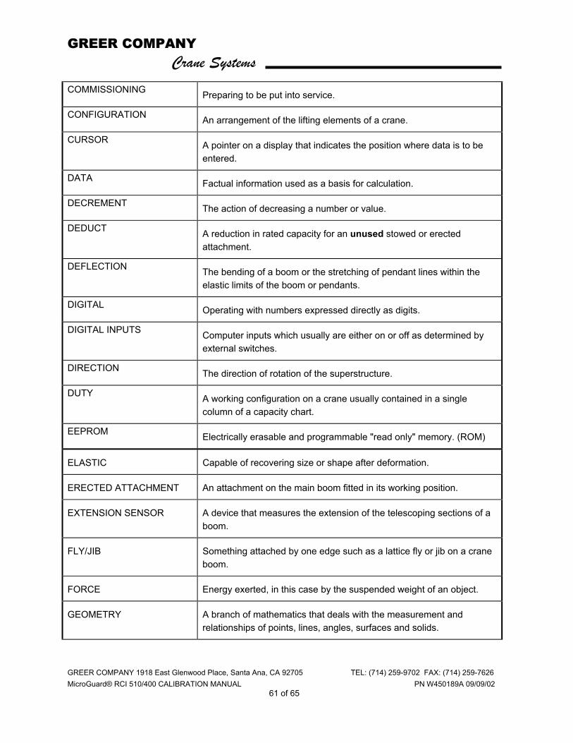
GREER COMPANY Crane Systems
GREER COMPANY 1918 East Glenwood Place, Santa Ana, CA 92705 TEL: (714) 259-9702 FAX: (714) 259-7626 MicroGuard® RCI 510/400 CALIBRATION MANUAL PN W450189A 09/09/02
61 of 65
COMMISSIONING Preparing to be put into service.
CONFIGURATION An arrangement of the lifting elements of a crane.
CURSOR A pointer on a display that indicates the position where data is to be entered.
DATA Factual information used as a basis for calculation.
DECREMENT The action of decreasing a number or value.
DEDUCT A reduction in rated capacity for an unused stowed or erected attachment.
DEFLECTION The bending of a boom or the stretching of pendant lines within the elastic limits of the boom or pendants.
DIGITAL Operating with numbers expressed directly as digits.
DIGITAL INPUTS Computer inputs which usually are either on or off as determined by external switches.
DIRECTION The direction of rotation of the superstructure.
DUTY A working configuration on a crane usually contained in a single column of a capacity chart.
EEPROM Electrically erasable and programmable "read only" memory. (ROM)
ELASTIC Capable of recovering size or shape after deformation.
ERECTED ATTACHMENT An attachment on the main boom fitted in its working position.
EXTENSION SENSOR A device that measures the extension of the telescoping sections of a boom.
FLY/JIB Something attached by one edge such as a lattice fly or jib on a crane boom.
FORCE Energy exerted, in this case by the suspended weight of an object.
GEOMETRY A branch of mathematics that deals with the measurement and relationships of points, lines, angles, surfaces and solids.
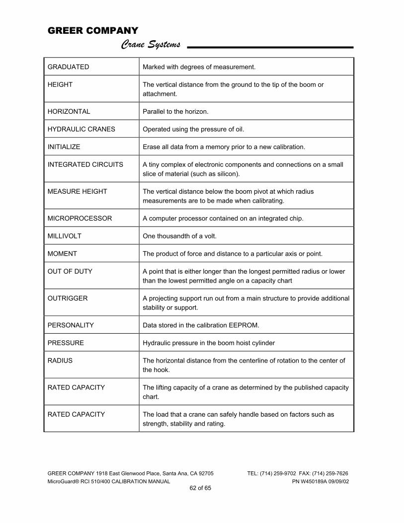
GREER COMPANY Crane Systems
GREER COMPANY 1918 East Glenwood Place, Santa Ana, CA 92705 TEL: (714) 259-9702 FAX: (714) 259-7626 MicroGuard® RCI 510/400 CALIBRATION MANUAL PN W450189A 09/09/02
62 of 65
GRADUATED Marked with degrees of measurement.
HEIGHT The vertical distance from the ground to the tip of the boom or attachment.
HORIZONTAL Parallel to the horizon.
HYDRAULIC CRANES Operated using the pressure of oil.
INITIALIZE Erase all data from a memory prior to a new calibration.
INTEGRATED CIRCUITS A tiny complex of electronic components and connections on a small slice of material (such as silicon).
MEASURE HEIGHT The vertical distance below the boom pivot at which radius measurements are to be made when calibrating.
MICROPROCESSOR A computer processor contained on an integrated chip.
MILLIVOLT One thousandth of a volt.
MOMENT The product of force and distance to a particular axis or point.
OUT OF DUTY A point that is either longer than the longest permitted radius or lower than the lowest permitted angle on a capacity chart
OUTRIGGER A projecting support run out from a main structure to provide additional stability or support.
PERSONALITY Data stored in the calibration EEPROM.
PRESSURE Hydraulic pressure in the boom hoist cylinder
RADIUS The horizontal distance from the centerline of rotation to the center of the hook.
RATED CAPACITY The lifting capacity of a crane as determined by the published capacity chart.
RATED CAPACITY The load that a crane can safely handle based on factors such as strength, stability and rating.
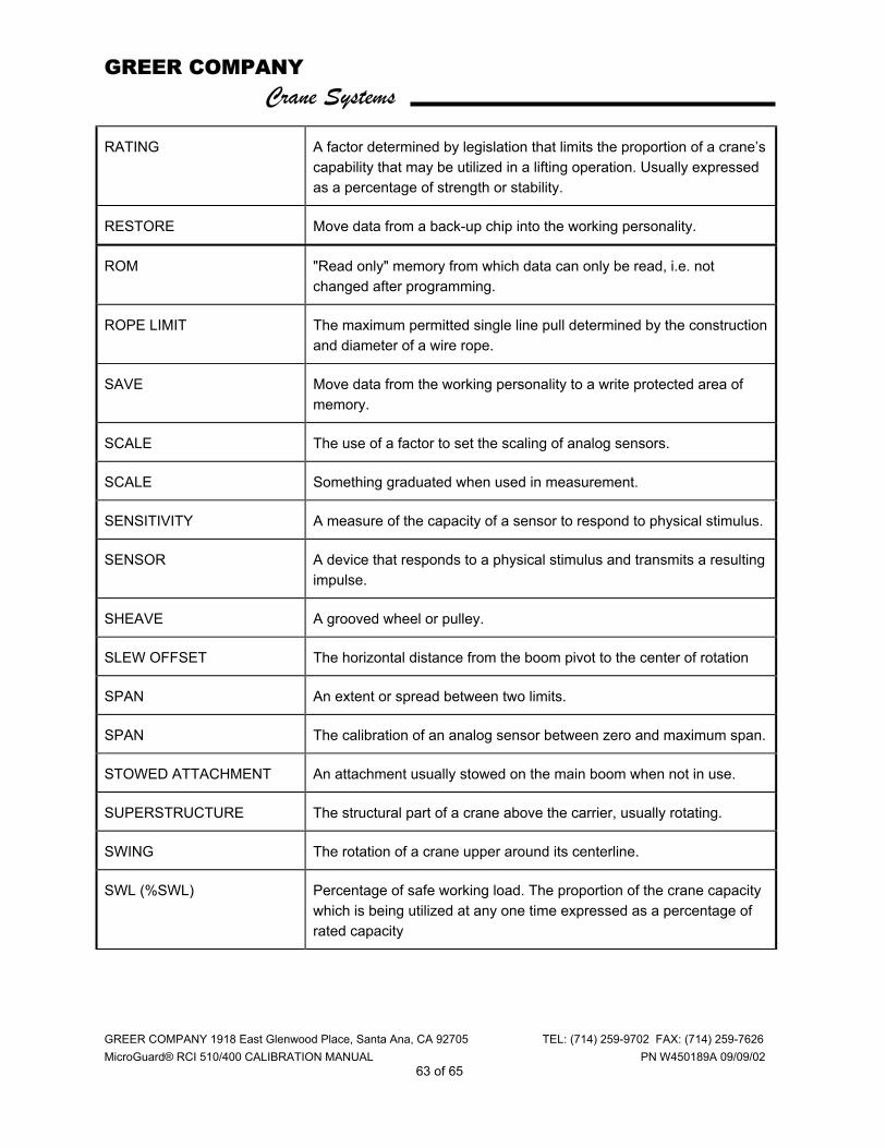
GREER COMPANY Crane Systems
GREER COMPANY 1918 East Glenwood Place, Santa Ana, CA 92705 TEL: (714) 259-9702 FAX: (714) 259-7626 MicroGuard® RCI 510/400 CALIBRATION MANUAL PN W450189A 09/09/02
63 of 65
RATING A factor determined by legislation that limits the proportion of a crane’s capability that may be utilized in a lifting operation. Usually expressed as a percentage of strength or stability.
RESTORE Move data from a back-up chip into the working personality.
ROM "Read only" memory from which data can only be read, i.e. not changed after programming.
ROPE LIMIT The maximum permitted single line pull determined by the construction and diameter of a wire rope.
SAVE Move data from the working personality to a write protected area of memory.
SCALE The use of a factor to set the scaling of analog sensors.
SCALE Something graduated when used in measurement.
SENSITIVITY A measure of the capacity of a sensor to respond to physical stimulus.
SENSOR A device that responds to a physical stimulus and transmits a resulting impulse.
SHEAVE A grooved wheel or pulley.
SLEW OFFSET The horizontal distance from the boom pivot to the center of rotation
SPAN An extent or spread between two limits.
SPAN The calibration of an analog sensor between zero and maximum span.
STOWED ATTACHMENT An attachment usually stowed on the main boom when not in use.
SUPERSTRUCTURE The structural part of a crane above the carrier, usually rotating.
SWING The rotation of a crane upper around its centerline.
SWL (%SWL) Percentage of safe working load. The proportion of the crane capacity which is being utilized at any one time expressed as a percentage of rated capacity
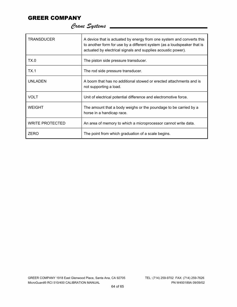
GREER COMPANY Crane Systems
GREER COMPANY 1918 East Glenwood Place, Santa Ana, CA 92705 TEL: (714) 259-9702 FAX: (714) 259-7626 MicroGuard® RCI 510/400 CALIBRATION MANUAL PN W450189A 09/09/02
64 of 65
TRANSDUCER A device that is actuated by energy from one system and converts this to another form for use by a different system (as a loudspeaker that is actuated by electrical signals and supplies acoustic power).
TX.0 The piston side pressure transducer.
TX.1 The rod side pressure transducer.
UNLADEN A boom that has no additional stowed or erected attachments and is not supporting a load.
VOLT Unit of electrical potential difference and electromotive force.
WEIGHT The amount that a body weighs or the poundage to be carried by a horse in a handicap race.
WRITE PROTECTED An area of memory to which a microprocessor cannot write data.
ZERO The point from which graduation of a scale begins.

GREER COMPANY Crane Systems
GREER COMPANY 1918 East Glenwood Place, Santa Ana, CA 92705 TEL: (714) 259-9702 FAX: (714) 259-7626 MicroGuard® RCI 510/400 CALIBRATION MANUAL PN W450189A 09/09/02
65 of 65