rbril/at/docs/msc_thesis_smn_balasubramanian.pdf · eindhoven university of technology masters...
TRANSCRIPT

EINDHOVEN UNIVERSITY OF TECHNOLOGY
MASTERS THESIS
Flexible Spin-Lock Model - Analysis andImplementation
Author:Sri Muthu NarayananBALASUBRAMANIAN
Supervisor:Dr. ir. Reinder J. BRIL
A thesis submitted in fulfillment of the requirementsfor the degree of Master of Science
in the
Systems Architecture and Networking groupDepartment of Mathematics and Computer Science
Committee members:Dr. MSc. Nabi NajafabadiDr. MSc. Moris Behnam
Lic. MSc. Sara Afshar
July 17, 2017


iii
Eindhoven University of Technology
Abstract
Department of Mathematics and Computer Science
Master of Science
Flexible Spin-Lock Model - Analysis and Implementation
by Sri Muthu Narayanan BALASUBRAMANIAN
The Flexible Spin-Lock Model (FSLM) unifies suspension-based and spin-based resource accessprotocols (RAP) for partitioned fixed-priority preemptive scheduling (P-FPPS) based real-timemultiprocessor platforms. P-FPPS and spin-based RAPs are prescribed for multiprocessor plat-forms by AUTOSAR [1], the standard for the automotive industry. Recent work [2] has been donein defining the protocol for FSLM and providing a schedulability analysis without accounting forthe implementation overheads.
In this thesis, an initial implementation of FSLM[3][4] in the OSEK/VDX-compliant Erika En-terprise RTOS on an Altera Nios II platform using 4 soft-core processors is used as the basis, uponwhich improvements are made to optimize the performance. The improvements include a fasterinter-core communication mechanism and memory optimization by using dual shared stacks percore instead of one stack per task. The thesis also includes recommendations and insights for fur-ther optimizing the performance by exploring the low-level hardware locks used by the operatingsystem kernel to enable mutual exclusion.
The improved implementation is then used to characterize the implementation overheadsrelated to resource access. The schedulability analysis of FSLM is extended to include the im-plementation overheads. The thesis also supplements the analysis with measurement results,enabling an analytical comparison of FSLM with the natively provided multiprocessor stack re-source policy (MSRP), which may serve as a guideline for the choice of FSLM or MSRP for aspecific application.


v
AcknowledgementsI would sincerely like to thank my graduation thesis supervisor Dr. ir. Reinder J. Bril at Eind-hoven University of Technology (TU/e) for his continuous support throughout the graduationthesis phase. Since the first day, Dr. Bril was always available whenever I had any questions, im-mediately providing me with appropriate guidance with his vast experience while also ensuringthat the thesis remained my own work. He was extremely prompt in providing feedback throughthe weekly discussions without which this work would have been impossible. It was indeed apleasure to work under his guidance.
I would also like to thank Dr. Moris Benham and Sara Afshar from Mälardalen University,Sweden for their timely guidance and suggestions for shaping the goals of the thesis. Their feed-back during critical phases of the thesis was helpful in spotting potential errors and rectifyingthem in a timely fashion.
I would like to extend my thanks to Dr. Paolo Gai from Evidence S.r.l., Italy, for providingvaluable knowledge transfer regarding the Erika Enterprise RTOS that helped in quick-startingthe thesis. I am also thankful to Mr. Richard Verhoeven from the Mathematics and ComputerSciences Department at TU/e for his practical support with the FPGA hardware. A special thanksto Dr. Nabi Najafabadi from TU/e for participating as the external examiner in the graduationcommittee.
I also would like to acknowledge the work performed by Maikel Verwielen in his Mastersthesis, providing detailed documentation regarding the internal workings of the Erika Enterpriseresource access functions and user manuals for creating multiprocessor systems on Altera basedFPGA platforms. His documentation proved to be very useful in getting acquainted with thehardware and software platforms in a short time period.
Finally, I express my gratitude to my parents and friends for their continuous encouragementand support throughout my Masters degree . . .
Sri Muthu Narayanan BALASUBRAMANIAN

vii
Contents
Abstract iii
Acknowledgements v
1 Introduction 11.1 Background . . . . . . . . . . . . . . . . . . . . . . . . . . . . . . . . . . . . . . . . . 21.2 Problem statement . . . . . . . . . . . . . . . . . . . . . . . . . . . . . . . . . . . . . 21.3 Research questions . . . . . . . . . . . . . . . . . . . . . . . . . . . . . . . . . . . . . 31.4 Objectives and goals . . . . . . . . . . . . . . . . . . . . . . . . . . . . . . . . . . . . 41.5 Contributions . . . . . . . . . . . . . . . . . . . . . . . . . . . . . . . . . . . . . . . . 51.6 Methodology . . . . . . . . . . . . . . . . . . . . . . . . . . . . . . . . . . . . . . . . 51.7 Reading guide . . . . . . . . . . . . . . . . . . . . . . . . . . . . . . . . . . . . . . . . 61.8 Thesis outline . . . . . . . . . . . . . . . . . . . . . . . . . . . . . . . . . . . . . . . . 7
2 Related work 92.1 Multiprocessor resource access protocols . . . . . . . . . . . . . . . . . . . . . . . . 9
2.1.1 Spin-based protocols . . . . . . . . . . . . . . . . . . . . . . . . . . . . . . . . 92.1.2 Suspension-based protocols . . . . . . . . . . . . . . . . . . . . . . . . . . . . 10
2.2 Memory utilization . . . . . . . . . . . . . . . . . . . . . . . . . . . . . . . . . . . . . 102.3 RAP implementation . . . . . . . . . . . . . . . . . . . . . . . . . . . . . . . . . . . . 112.4 Overhead analysis . . . . . . . . . . . . . . . . . . . . . . . . . . . . . . . . . . . . . . 12
3 Preliminaries 133.1 Real-time scheduling model . . . . . . . . . . . . . . . . . . . . . . . . . . . . . . . . 13
3.1.1 Basic model . . . . . . . . . . . . . . . . . . . . . . . . . . . . . . . . . . . . . 133.1.2 Resource sharing . . . . . . . . . . . . . . . . . . . . . . . . . . . . . . . . . . 13
3.2 FSLM overview . . . . . . . . . . . . . . . . . . . . . . . . . . . . . . . . . . . . . . . 143.2.1 Resource sharing rules in FSLM . . . . . . . . . . . . . . . . . . . . . . . . . 143.2.2 Special spin-lock priorities . . . . . . . . . . . . . . . . . . . . . . . . . . . . . 153.2.3 Recap of existing analysis without overheads . . . . . . . . . . . . . . . . . . 15
3.3 System overview . . . . . . . . . . . . . . . . . . . . . . . . . . . . . . . . . . . . . . 173.3.1 Hardware system . . . . . . . . . . . . . . . . . . . . . . . . . . . . . . . . . . 173.3.2 Software system . . . . . . . . . . . . . . . . . . . . . . . . . . . . . . . . . . 18
4 Inter-core communication 214.1 The spin-lock variable . . . . . . . . . . . . . . . . . . . . . . . . . . . . . . . . . . . 21
4.1.1 Spinning on a global spin-lock . . . . . . . . . . . . . . . . . . . . . . . . . . 214.1.2 Spinning on a local spin-lock . . . . . . . . . . . . . . . . . . . . . . . . . . . 22
4.2 Remote Notification mechanism . . . . . . . . . . . . . . . . . . . . . . . . . . . . . 254.3 Dedicated Interrupts . . . . . . . . . . . . . . . . . . . . . . . . . . . . . . . . . . . . 26
4.3.1 Motivation for Dedicated Interrupts . . . . . . . . . . . . . . . . . . . . . . . 264.3.2 Design . . . . . . . . . . . . . . . . . . . . . . . . . . . . . . . . . . . . . . . . 274.3.3 Implementation . . . . . . . . . . . . . . . . . . . . . . . . . . . . . . . . . . . 284.3.4 Verification . . . . . . . . . . . . . . . . . . . . . . . . . . . . . . . . . . . . . 33
4.4 Performance comparison . . . . . . . . . . . . . . . . . . . . . . . . . . . . . . . . . . 364.5 Compatibility for spin-lock priorities in [LP,CP) . . . . . . . . . . . . . . . . . . . . 384.6 Recommendations for integration with Erika Enterprise . . . . . . . . . . . . . . . . 38
viii
5 Dual shared stacks 415.1 Runtime stack space . . . . . . . . . . . . . . . . . . . . . . . . . . . . . . . . . . . . 415.2 Stack requirement - FSLM . . . . . . . . . . . . . . . . . . . . . . . . . . . . . . . . . 425.3 Stack configuration options in Erika Enterprise . . . . . . . . . . . . . . . . . . . . . 42
5.3.1 CPU object . . . . . . . . . . . . . . . . . . . . . . . . . . . . . . . . . . . . . . 435.3.2 OS object . . . . . . . . . . . . . . . . . . . . . . . . . . . . . . . . . . . . . . . 435.3.3 CPU_DATA section . . . . . . . . . . . . . . . . . . . . . . . . . . . . . . . . . 445.3.4 TASK object . . . . . . . . . . . . . . . . . . . . . . . . . . . . . . . . . . . . . 45
5.4 Dual shared stack for FSLM in Erika . . . . . . . . . . . . . . . . . . . . . . . . . . . 455.4.1 RT-Druid auto code-generation for stack configuration . . . . . . . . . . . . 455.4.2 Configuration for dual shared stack . . . . . . . . . . . . . . . . . . . . . . . 475.4.3 Memory size calculation for dual shared stacks . . . . . . . . . . . . . . . . . 48
5.5 Memory savings associated with dual shared stack . . . . . . . . . . . . . . . . . . 51
6 FSLM tool 536.1 Introduction . . . . . . . . . . . . . . . . . . . . . . . . . . . . . . . . . . . . . . . . . 53
6.1.1 Spin-lock parameters in FSLM implementation . . . . . . . . . . . . . . . . . 536.1.2 Stack memory parameters . . . . . . . . . . . . . . . . . . . . . . . . . . . . . 54
6.2 Requirements . . . . . . . . . . . . . . . . . . . . . . . . . . . . . . . . . . . . . . . . 546.3 Design and implementation . . . . . . . . . . . . . . . . . . . . . . . . . . . . . . . . 55
6.3.1 Working . . . . . . . . . . . . . . . . . . . . . . . . . . . . . . . . . . . . . . . 556.3.2 Example execution scenario . . . . . . . . . . . . . . . . . . . . . . . . . . . . 576.3.3 Documentation . . . . . . . . . . . . . . . . . . . . . . . . . . . . . . . . . . . 57
7 Overheads 597.1 Classification of overhead scenarios . . . . . . . . . . . . . . . . . . . . . . . . . . . 597.2 Identification of overhead components . . . . . . . . . . . . . . . . . . . . . . . . . . 61
7.2.1 Resource request overheads . . . . . . . . . . . . . . . . . . . . . . . . . . . . 617.2.2 Resource access overheads . . . . . . . . . . . . . . . . . . . . . . . . . . . . 617.2.3 Resource release overheads . . . . . . . . . . . . . . . . . . . . . . . . . . . . 63
7.3 Incorporating the overhead components in scenarios . . . . . . . . . . . . . . . . . 647.4 Overheads in MSRP . . . . . . . . . . . . . . . . . . . . . . . . . . . . . . . . . . . . . 647.5 Extending the schedulability analysis . . . . . . . . . . . . . . . . . . . . . . . . . . 65
7.5.1 MSRP . . . . . . . . . . . . . . . . . . . . . . . . . . . . . . . . . . . . . . . . . 657.5.2 FSLM-HP spin-lock approach . . . . . . . . . . . . . . . . . . . . . . . . . . . 677.5.3 FSLM-CP spin-lock approach . . . . . . . . . . . . . . . . . . . . . . . . . . . 69
8 Measurements and analysis 718.1 Hardware setup . . . . . . . . . . . . . . . . . . . . . . . . . . . . . . . . . . . . . . . 71
8.1.1 GNU profiler . . . . . . . . . . . . . . . . . . . . . . . . . . . . . . . . . . . . 718.1.2 High resolution timers . . . . . . . . . . . . . . . . . . . . . . . . . . . . . . . 718.1.3 Performance counter cores . . . . . . . . . . . . . . . . . . . . . . . . . . . . 72
8.2 Software setup . . . . . . . . . . . . . . . . . . . . . . . . . . . . . . . . . . . . . . . . 738.2.1 Software programming model for performance counter cores . . . . . . . . 738.2.2 Setup for monitoring real-time performance . . . . . . . . . . . . . . . . . . 748.2.3 Code instrumentation . . . . . . . . . . . . . . . . . . . . . . . . . . . . . . . 768.2.4 The application . . . . . . . . . . . . . . . . . . . . . . . . . . . . . . . . . . . 77
8.3 Measuring the overheads . . . . . . . . . . . . . . . . . . . . . . . . . . . . . . . . . 778.3.1 Context switching overheads . . . . . . . . . . . . . . . . . . . . . . . . . . . 788.3.2 Measurement results . . . . . . . . . . . . . . . . . . . . . . . . . . . . . . . . 78
8.4 Analytical evaluation . . . . . . . . . . . . . . . . . . . . . . . . . . . . . . . . . . . . 798.4.1 Analysis scenario . . . . . . . . . . . . . . . . . . . . . . . . . . . . . . . . . . 808.4.2 Analysis results . . . . . . . . . . . . . . . . . . . . . . . . . . . . . . . . . . . 81

ix
9 Low-level hardware locks 859.1 Hardware mutex options in Erika . . . . . . . . . . . . . . . . . . . . . . . . . . . . . 859.2 Drawback of using one mutex device for the system . . . . . . . . . . . . . . . . . . 86
9.2.1 Existing scenario . . . . . . . . . . . . . . . . . . . . . . . . . . . . . . . . . . 869.2.2 Alternative solution . . . . . . . . . . . . . . . . . . . . . . . . . . . . . . . . 879.2.3 Motivation for existing design by Erika Enterprise . . . . . . . . . . . . . . . 88
9.3 Experimental measurement . . . . . . . . . . . . . . . . . . . . . . . . . . . . . . . . 889.3.1 Measurement setup . . . . . . . . . . . . . . . . . . . . . . . . . . . . . . . . 899.3.2 Measurement results . . . . . . . . . . . . . . . . . . . . . . . . . . . . . . . . 91
10 Conclusions 9310.1 Outcomes of the thesis . . . . . . . . . . . . . . . . . . . . . . . . . . . . . . . . . . . 9310.2 Future work . . . . . . . . . . . . . . . . . . . . . . . . . . . . . . . . . . . . . . . . . 94
A User manual - FPGA hardware and software design 95A.1 Hardware manual . . . . . . . . . . . . . . . . . . . . . . . . . . . . . . . . . . . . . . 95A.2 Creating the hardware design . . . . . . . . . . . . . . . . . . . . . . . . . . . . . . . 95
A.2.1 DE2-115 system builder . . . . . . . . . . . . . . . . . . . . . . . . . . . . . . 95A.2.2 Create the project in Quartus II . . . . . . . . . . . . . . . . . . . . . . . . . . 96A.2.3 Adding 4 Nios II cores . . . . . . . . . . . . . . . . . . . . . . . . . . . . . . . 97A.2.4 Adding internal memory to the system . . . . . . . . . . . . . . . . . . . . . 99A.2.5 Adding a Mutex to the design . . . . . . . . . . . . . . . . . . . . . . . . . . 99A.2.6 Inter-core interrupt input lines . . . . . . . . . . . . . . . . . . . . . . . . . . 99A.2.7 Inter-core interrupt output lines . . . . . . . . . . . . . . . . . . . . . . . . . 101A.2.8 Adding a button input for each core . . . . . . . . . . . . . . . . . . . . . . . 102A.2.9 Adding 4 LEDs for each core in the system . . . . . . . . . . . . . . . . . . . 102A.2.10 Modifying the Nios II core properties . . . . . . . . . . . . . . . . . . . . . . 103A.2.11 Adding JTAG UART and performance counters . . . . . . . . . . . . . . . . 103A.2.12 Connecting and rearranging the components . . . . . . . . . . . . . . . . . . 103A.2.13 Generate the design . . . . . . . . . . . . . . . . . . . . . . . . . . . . . . . . 103
A.3 Synthesis of the design . . . . . . . . . . . . . . . . . . . . . . . . . . . . . . . . . . . 104A.3.1 Pin assignment . . . . . . . . . . . . . . . . . . . . . . . . . . . . . . . . . . . 105A.3.2 Analysis and synthesis . . . . . . . . . . . . . . . . . . . . . . . . . . . . . . . 106
A.4 Software creation . . . . . . . . . . . . . . . . . . . . . . . . . . . . . . . . . . . . . . 107
B Flex-Tool guide 109B.1 Tool usage . . . . . . . . . . . . . . . . . . . . . . . . . . . . . . . . . . . . . . . . . . 109B.2 Auto generated documentation . . . . . . . . . . . . . . . . . . . . . . . . . . . . . . 113
Bibliography 117

xi
List of Figures
1.1 Methodology . . . . . . . . . . . . . . . . . . . . . . . . . . . . . . . . . . . . . . . . 5
3.1 Illustration of a task spinning while waiting on a global resource [4]. . . . . . . . . 153.2 Nios II embedded system design flow [36]. . . . . . . . . . . . . . . . . . . . . . . . 173.3 Overview of the hardware system created for the study. . . . . . . . . . . . . . . . 183.4 Development view of Erika [4]. . . . . . . . . . . . . . . . . . . . . . . . . . . . . . . 19
4.1 Spinning on a global spin-lock. . . . . . . . . . . . . . . . . . . . . . . . . . . . . . . 224.2 Spinning on a local spin-lock. . . . . . . . . . . . . . . . . . . . . . . . . . . . . . . . 244.3 Spinning on a local spin-lock. . . . . . . . . . . . . . . . . . . . . . . . . . . . . . . . 244.4 Inter core interrupts hardware connection for Remote Notifications [4]. . . . . . . 264.5 Calls graph for the function EE_oo_GetResource(). . . . . . . . . . . . . . . . . 284.6 Calls graph for the function EE_oo_ReleaseResource(). . . . . . . . . . . . . . 294.7 The EE_di_send() function. . . . . . . . . . . . . . . . . . . . . . . . . . . . . . . . . 314.8 The EE_di_handler() function. . . . . . . . . . . . . . . . . . . . . . . . . . . . . . . . 324.9 Flow chart of EE_di_execute(). . . . . . . . . . . . . . . . . . . . . . . . . . . . 334.10 Remote Notification component functions with the difference between DI and RN
highlighted. . . . . . . . . . . . . . . . . . . . . . . . . . . . . . . . . . . . . . . . . . 344.11 Comparison of execution times of component functions of Remote Notification
(RN) and Dedicated Interrupts (DI). . . . . . . . . . . . . . . . . . . . . . . . . . . . 37
5.1 FSLM single stack evolutions under HP and CP approaches. . . . . . . . . . . . . . 415.2 Partial overview of RT-Druid automatic code-generation architecture . . . . . . . . 465.3 Example Dual shared stack overview. . . . . . . . . . . . . . . . . . . . . . . . . . . 49
6.1 Context of Flex-Tool in the software build process. . . . . . . . . . . . . . . . . . . 566.2 Sequence diagram for Flex-Tool actions. . . . . . . . . . . . . . . . . . . . . . . . . . 576.3 Screen-shot from Flex-Tool execution. . . . . . . . . . . . . . . . . . . . . . . . . . . 58
7.1 Overhead scenarios in the implementation of MSRP and FSLM w.r.t resource access. 607.2 Resource request overheads in FSLM (new implementation). . . . . . . . . . . . . 617.3 Resource access overheads in FSLM (new implementation). . . . . . . . . . . . . . 627.4 Example time-line scenario illustrating blocking context switch . . . . . . . . . . . 637.5 Resource release overheads in FSLM (new implementation). . . . . . . . . . . . . . 637.6 Resource access overheads in MSRP (native implementation). . . . . . . . . . . . . 647.7 Resource release overheads in MSRP (native implementation). . . . . . . . . . . . 657.8 Overview of all overhead components for FSLM. . . . . . . . . . . . . . . . . . . . . 667.9 Example time-line scenario illustrating Remote Holding Time overheads . . . . . . 68
8.1 Performance counters in SOPC design . . . . . . . . . . . . . . . . . . . . . . . . . . 738.2 Output of JTAG UART port from CPU 0 on the terminal. . . . . . . . . . . . . . . . 758.3 Structure of the example application used for measurements. . . . . . . . . . . . . . 778.4 Relative sizes of the overheads in MSRP and FSLM (initial and new) implementa-
tions. . . . . . . . . . . . . . . . . . . . . . . . . . . . . . . . . . . . . . . . . . . . . . 798.5 Predictability of the cumulative overheads in MSRP, FSLM (old and new). . . . . . 808.6 Analytical evaluation scenario. . . . . . . . . . . . . . . . . . . . . . . . . . . . . . . 818.7 The response time of τhp as a function of the gcs lengths of lower priority and
remote tasks under MSRP, FSLM-CP and FSLM-HP with 2 processors. . . . . . . . 82

xii
8.8 The response time of τhp as a function of the gcs lengths of lower priority & remotetasks under MSRP, FSLM-CP & FSLM-HP with 2 & 3 processors. . . . . . . . . . . 83
8.9 The response time of τhp as a function of the gcs lengths of lower priority andremote tasks under MSRP and FSLM-CP with 2, 3, 4 and 8 processors. . . . . . . . 84
9.1 Hardware definition of mutex peripheral. . . . . . . . . . . . . . . . . . . . . . . . . 859.2 Using the same mutex for two unrelated shared data structures (steps 1 and 2). . . 879.3 Using the same mutex for two unrelated shared data structures (steps 3 and 4). . . 879.4 Using individual mutex for each shared data structure. . . . . . . . . . . . . . . . . 889.5 Interval timer hardware on cpu 1 and cpu 2. . . . . . . . . . . . . . . . . . . . . . . 899.6 Execution times for 105 iterations of mutex acquisition and release for 2 and 3 CPUs
under contention and no contention. . . . . . . . . . . . . . . . . . . . . . . . . . . . 91
A.1 DE2-115 system builder screen . . . . . . . . . . . . . . . . . . . . . . . . . . . . . . 96A.2 Output files generated by the system builder . . . . . . . . . . . . . . . . . . . . . . 96A.3 Opening the project file in Quartus II . . . . . . . . . . . . . . . . . . . . . . . . . . . 97A.4 Create a new system in SOPC builder . . . . . . . . . . . . . . . . . . . . . . . . . . 97A.5 Add a Nios II processor to the design - step 1 . . . . . . . . . . . . . . . . . . . . . . 98A.6 Add a Nios II processor to the design - step 2 . . . . . . . . . . . . . . . . . . . . . . 98A.7 Add a Nios II processor to the design - step 3 . . . . . . . . . . . . . . . . . . . . . . 98A.8 Adding internal memory to the design - step 1 . . . . . . . . . . . . . . . . . . . . . 99A.9 Adding internal memory to the design - step 2 . . . . . . . . . . . . . . . . . . . . . 100A.10 Adding a mutex to the design - step 1 . . . . . . . . . . . . . . . . . . . . . . . . . . 100A.11 Adding a mutex to the design - step 2 . . . . . . . . . . . . . . . . . . . . . . . . . . 101A.12 Adding an input interrupt line . . . . . . . . . . . . . . . . . . . . . . . . . . . . . . 101A.13 Adding a input interrupt line - step 3 . . . . . . . . . . . . . . . . . . . . . . . . . . . 101A.14 Adding output interrupt lines - step 1 . . . . . . . . . . . . . . . . . . . . . . . . . . 102A.15 Adding button inputs . . . . . . . . . . . . . . . . . . . . . . . . . . . . . . . . . . . . 102A.16 Modifying core properties . . . . . . . . . . . . . . . . . . . . . . . . . . . . . . . . . 103A.17 Rearrange and connect components . . . . . . . . . . . . . . . . . . . . . . . . . . . 104A.18 Successful completion of system generation . . . . . . . . . . . . . . . . . . . . . . . 104A.19 Top entity in project navigator . . . . . . . . . . . . . . . . . . . . . . . . . . . . . . . 105A.20 Copy the contents of the module from four_core_SOPC.v file . . . . . . . . . . . 105A.21 Analysis and synthesis . . . . . . . . . . . . . . . . . . . . . . . . . . . . . . . . . . . 106
B.1 Flex-Tool example summary of application and prompt for user input . . . . . . . 110B.2 Refresh and build the project . . . . . . . . . . . . . . . . . . . . . . . . . . . . . . . 111B.3 Running the program on the hardware . . . . . . . . . . . . . . . . . . . . . . . . . . 111

xiii
List of Tables
3.3 Hardware design specifications. . . . . . . . . . . . . . . . . . . . . . . . . . . . . . . 18
4.1 Functional verification of DI mechanism - Test cases. . . . . . . . . . . . . . . . . . . 364.2 Comparison of execution times of component functions of Remote Notification
(RN) and Dedicated Interrupts (DI) for 75 samples (25 per core). . . . . . . . . . . 364.3 Comparison of DI integration options. . . . . . . . . . . . . . . . . . . . . . . . . . . 39
8.1 Comparison of measurement methods. . . . . . . . . . . . . . . . . . . . . . . . . . 728.2 Resource usage of performance counters. . . . . . . . . . . . . . . . . . . . . . . . . 738.3 Performance counter macros and functions. . . . . . . . . . . . . . . . . . . . . . . . 748.4 CPI calculation for context switching overheads . . . . . . . . . . . . . . . . . . . . 788.5 Overheads in MSRP and FSLM (in terms of number of cycles). . . . . . . . . . . . . 79
9.1 Execution times for 105 iterations of mutex acquisition and release for CPU 1 andCPU 2 under contention and no contention. . . . . . . . . . . . . . . . . . . . . . . . 91
9.2 Execution times for 105 iterations of mutex acquisition and release for CPUs 1, 2and 3 under contention and no contention. . . . . . . . . . . . . . . . . . . . . . . . 92


xv
Listings
4.1 RN message types in the original Erika Enterprise. . . . . . . . . . . . . . . . . . . . 274.2 Updated code of EE_oo_GetResource(). . . . . . . . . . . . . . . . . . . . . . . . 294.3 Updated code of EE_oo_ReleaseResource(). . . . . . . . . . . . . . . . . . . . . 304.4 Pseudo code for EE_di_send() function. . . . . . . . . . . . . . . . . . . . . . . . 314.5 C-code for EE_di_send() function. . . . . . . . . . . . . . . . . . . . . . . . . . . . 314.6 C-code for EE_di_handler() function. . . . . . . . . . . . . . . . . . . . . . . . . 324.7 C-code for EE_di_execute() function. . . . . . . . . . . . . . . . . . . . . . . . . 325.1 Example 2-core OIL file snippet - CPU object and OS object. . . . . . . . . . . . . . 435.2 Example OIL file snippet - Task objects with shared and private stacks. . . . . . . . 455.3 Example auto-generated stack configuration - snippet from eecfg.c. . . . . . . . 475.4 Example modified dual stack configuration. . . . . . . . . . . . . . . . . . . . . . . . 485.5 OIL file snippet showing IRQ_STACK configuration. . . . . . . . . . . . . . . . . . . 496.1 Snippet of “extern” configuration parameters from ee_internal.h. . . . . . . . 536.2 Snippet of example initialization of variables in cpu1_main.c. . . . . . . . . . . . 548.1 Snippet from ee_fslm_measure.h showing the measurement data structures. . 748.2 Snippet from fslm.h showing the measurement data structures. . . . . . . . . . . 758.3 Snippet from cpu0_main.c showing the initialization of MeasureQ. . . . . . . . . 758.4 Snippet of EE_hal_spin_out() showing the code instrumentation for measure-
ment of OHDIsnd. . . . . . . . . . . . . . . . . . . . . . . . . . . . . . . . . . . . . . . . 76
8.5 Snippet from ee_fslm_measure.h showing the measurement macros. . . . . . . 779.1 Snippet section guarded by mutex in EE_hal_spin_out(). . . . . . . . . . . . . 869.2 Snippet of example alarm initialization in cpu1_main.c. . . . . . . . . . . . . . . . 899.3 Mutex interference measurement code setup snippet. . . . . . . . . . . . . . . . . . 90A.1 Contents specifying pin assignments that must be added to the four_core_demo.v
file . . . . . . . . . . . . . . . . . . . . . . . . . . . . . . . . . . . . . . . . . . . . . . . 105B.1 Convention for mentioning the TASK STACK attribute in OIL file . . . . . . . . . . 110B.2 CPU application file variables . . . . . . . . . . . . . . . . . . . . . . . . . . . . . . . 111


xvii
List of Abbreviations
API Application Programming Interface
EDF Earliest Deadline First
FIFO First In First Out
FMLP Flexible Multiprocessor Locking Protocol
FSLM Flexible Spin-Lock Model
FPGA Field Programmable Gate Array
IDE Integrated Development Environment
IP Intellectual Property
IRQ Interrupt ReQuest
ISR Interrupt Service Routine
LBL Local Blocking due to Local resources
LBG Local Blocking due to Global resources
LE Logic Element
LED Light Emitting Diode
LIFO Last In First Out
MPCP Multiprocessor Priority Ceiling Protocol
MSRP Multiprocessor Stack Resource Policy
OIL OSEK Imlementation Language
OSEK Offene Systeme und deren schnittstellen für die Elektronik in Kraftfahrzeugen(Open Systems and their interfaces for the Electronics in motor vehicles)
P-FPPS Partitioned Fixed Priority Preemptive Scheduling
PCP Priority Ceiling Protocol
PIP Priority Inheritance Protocol
RAM Random Access Memory
RAP Resource Access Protocol
RM Rate Monotonic
RN Remote Notifications
RTOS Real-Time Operating System
SOC System On Chip
SOPC System On a Programmable Chip
SRP Stack Resource Policy
VDX Vehicle Distributed eXecutive


1
Chapter 1
Introduction
The complexity of embedded systems are growing at a rapid rate, especially in the last threedecades. As a direct consequence of Moore’s law, the processors are becoming increasingly pow-erful causing the competing companies in the international market to pack more functionalityin their devices to attract consumers. As a result, we now have small devices controlling seem-ingly simple tasks such as house heating with the capability of processing orders of magnitudemore information than the computer systems used on the Apollo missions that helped humanityreach the moon. As the physical size of a transistor used in a processor started to reach its min-imum limit in the scale of nanometers, engineers started moving towards systems with multipleprocessors rather than trying to fit more processing power into a single processor.
The permeation of multiprocessor platforms in embedded systems has resulted in an increasedneed for providing efficient resource management and scheduling methods. Real-time embeddedsystems are highly resource constrained and are often used for safety critical applications de-manding time critical operations, thereby requiring resource handling techniques that guaranteemeeting the application deadlines with predictable response times. In a typical multi-processorreal-time embedded system, the tasks residing on multiple processing cores access shared globalresources. Efficient resource sharing protocols are required to co-ordinate the resource accessamong competing cores without inducing overheads.
In traditional lock-based resource access protocols (RAPs)1 for real-time multi-processor plat-forms, a task that is blocked on a global resource either performs a non-preemptive busy wait, i.e.spins, or releases the processor, i.e. suspends.
In case of non-preemptive spinning, the task that is blocked on a resource boosts its priority tothe highest priority level on the core and thus becomes non-preemptable. The task registers itselfon the resource queue and waits for the resource to become available. For the entire duration thata task is blocked on a global resource in a core, it remains as the active (running) task althoughno useful work is being done. When the resource finally becomes available, the task acquiresthe resource and lowers the priority to its original level only after the completion of the resourceusage (referred to as the global critical section).
On the other hand, in a suspension based protocol, when a task is blocked on a resource, itrelinquishes the processor to other tasks by registering itself on the resource queue and suspend-ing itself. Other tasks on the core are now free to execute while the requesting task is suspended.When the resource becomes available, the requesting task preempts any other task that is run-ning on the core irrespective of its priority level and acquires the resource. It raises its priorityto a non-preemptive level and executes the global critical section. The Multiprocessor Stack Re-source Policy (MSRP) [5] is an example for a spin-based protocol while the Multiprocessor PriorityCeiling Protocol (MPCP) [6] is an example for a suspension-based protocol.
While it may seem that out of the two above approaches, a suspension based protocol offershigh CPU utilization, it must be noted that switching between tasks is not instantaneous. Thetime taken for performing a context switch between tasks can induce significant overheads in thesystem. Hence, it is important to carefully consider the effects of the resource access protocol onthe worst-case response times of the tasks by accounting for the blocking times and overheadsinduced by the protocol. A solution that provides a fine balance between the two traditionalmethods might be desirable.
The Flexible Spin-Lock Model (FSLM) [2] unifies both traditional approaches for partitionedfixed-priority preemptive scheduling (P-FPPS) by introducing a spin-lock priority for each pro-cessor, allowing the blocked task to spin at an arbitrary priority level. In partitioned systems, the
1In this report the terms resource sharing protocol and resource access protocol are used interchangeably

2 Chapter 1. Introduction
tasks are mapped onto the processors statically (off-line). P-FPPS and spin-based global RAPs arealso prescribed for multi-processor platforms by AUTOSAR [1], the standard for the automotiveindustry.
Now, we can treat non-preemptive spin-based protocols (like MSRP) as using the highest pri-ority (HP) as spin-lock priority whereas suspension based protocols (like MPCP) as using theLowest Priority (LP) as spin-lock priority. Although FSLM allows for the choice of an arbitraryspin-lock priority, a particular range of spin-lock priorities are of primary interest since it hasbeen found to significantly improve the schedulability. One such spin-lock priority is called theceiling priority (CP) defined as the highest resource ceiling of global resources on as core. In otherwords, CP is the priority of the task with the highest priority among all tasks on the core whichuse a global resource. Initial simulation results based on the developed theory [7] confirm theexpectations with respect to improved schedulability under CP when compared to HP. The re-mainder of the thesis considers spin-lock priorities in the range of [CP, HP] for FSLM. The focusof the thesis is to create an efficient implementation of FSLM and study the runtime overheadsinduced, characterize and incorporate them in the schedulability analysis.
1.1 Background
The Flexible Spin-Lock Model [2](FSLM) unifies spin-based and suspension-based resource shar-ing protocols for partitioned fixed priority preemptive scheduling (P-FPPS) based real-time mul-tiprocessor systems by explicitly identifying the spin-lock priority as a parameter. Analysis forFSLM has been developed, assuming the implementation overhead could be ignored. An ini-tial implementation of FSLM [3][4] in Erika Enterprise2 [8] has been realized and instantiatedon an Altera Nios II3 platform [9] using four soft-processing cores4. The initial implementationwas complemented with measurement results. The initial implementation was hampered by thelimitations of the FPGA development board, an Altera DE0, and left various topics for furtherinvestigation. To gain a better understanding of the implementation overheads, it is desirable tomove towards a better development platform that does not limit the experiments that could beperformed and has sufficient resources to allow improvements to the initial implementation.
1.2 Problem statement
During the initial implementation, a strong correlation between the memory configuration (off-chip, on-chip, type of memory) and the implementation overhead was noted. Due to the un-availability of sufficient on-chip memory, shared data structures were moved to off-chip memorydevices that contributed to increased overheads. Selecting a hardware platform that providesappropriate memory of the right size may therefore strongly influence the overheads.
Second, the re-use of Remote Notification (RN) mechanism5 for the initial implementation ofFSLM turned out to be extremely inefficient. The RN mechanism uses a system of shared mem-ory based data structures and inter-processor hardware interrupt lines to achieve communicationbetween the processors in the system. Other mechanisms, such as dedicated interrupt lines forFSLM, which do not use shared memory, may be more appropriate.
Third, the existing implementation (the Erika Enterprise RTOS itself) only uses a one (low-level) hardware mutex to regulate mutual exclusive access to various shared data structures be-tween processors in the system, which may therefore become a limited resource and a bottleneck.
Fourth, FSLM allows the usage of just two stacks (instead of one stack per task) [7] for spin-lock priorities in [CP, HP), which may significantly reduce the memory requirements of the sys-tem. However, the initial implementation uses one stack per task in the system. It may be ben-eficial to implement the dual shared stack and explore the memory savings offered by such amethod.
Finally, the schedulability analysis for FSLM provided in [2] does not take into account theimplementation overheads. It is therefore beneficial to identify, measure and characterize the
2Erika Enterprise is a free of charge open-source OSEK/VDX Hard Real Time Operating System3Nios II is a 32-bit soft processor core IP block designed for Altera FPGAs [9]4In this report, the terms processor and core are used interchangeably5Remote Notifications are used by the Erika kernel to enable inter-core communication in multiprocessor SOCs. Ex-
plained further in Chapter 4.

1.3. Research questions 3
induced implementation overheads and accommodate them in the schedulability analysis to pro-vide better scheduling estimates.
1.3 Research questions
This section presents a list of research questions that give rise to the primary objectives of thethesis. The analysis of the research questions presented below is used for the identification ofthe objectives. The research questions are revisited in later chapters of the report where they areanswered based on the findings from the thesis.
Question 1 What are the guidelines for choosing FSLM over MSRP for a given application?While ignoring the runtime overheads, preemptive spin-based protocols such as FSLM have
been shown to outperform non-preemptive protocols such as MSRP. It is desirable to know froman implementation perspective if FSLM outperforms MSRP with runtime overheads included.However, from the initial implementation of FSLM [3] [4], it has been identified that significantruntime overheads are encountered as a part of FSLM which are not incurred in MSRP. To answerthe question, an efficient implementation of FSLM is required. The overheads incurred in theimplementations of FSLM and MSRP must then be measured. The overheads should be incorpo-rated into the schedulability analysis to enable a comparison between MSRP and FSLM from apractical perspective. By choosing appropriate spin-lock priority levels other than HP for FSLM,considering the response time of high priority tasks, FSLM might outperform MSRP when theremote blocking time in MSRP exceeds the cumulative runtime overheads induced in FSLM. Forremote blocking times to be sufficiently large, it might help to consider longer global critical sec-tion lengths and systems with more processors.
Question 2 Is the dual shared stack implementation in FSLM for spin-lock priorities in [CP, HP) feasible?What are the benefits of such an implementation?
The default tooling provided by Erika Enterprise RTOS does not explicitly allow for the con-figuration of dual shared stacks. Hence, a new implementation with support for such sharedstacks must be created to examine the feasibility and the ease of creation of such a system. Stackspace saving in a shared stack context is usually achieved only when multiple tasks occupy thesame preemption level, thereby ensuring that such tasks can never occur in the stack simultane-ously. However, while dealing with the worst-case scenario, under FSLM, all tasks are assumedto have unique priority levels (preemption level is considered to be equal to the priority). Hence,even with stack sharing, the total memory requirement would remain unchanged. However,since FSLM is a preemptive spin-based protocol, tasks can be interrupted meaning the interruptrequests (IRQs) require their own stack space. Thus memory space required by the IRQs may beminimized by adopting the dual shared stacks implementation.
Question 3 How does a dedicated interrupt based inter-core communication mechanism for notifyingresource release between the cores compare to the existing generic shared memory based communicationmechanism for FSLM in the range [CP, HP]?
Choosing a specific range of spin-lock priorities in FSLM, i.e., [CP, HP] enables at most onetask to be waiting for a global resource in a core at any given time. Thus a simple interruptbased inter-core communication mechanism may be sufficient to notify cores regarding the re-lease of a resource. The initial implementation of FSLM [3] [4] showed that by using the existinggeneric shared memory based Remote Notification mechanism, significant runtime overheads areincurred. An implementation using dedicated interrupts must therefore be made to show that it ispractically feasible for such a system to achieve communication regarding resource release whilealso reducing the overheads. In addition, for a full fledged kernel, both mechanisms might haveto co-exist to offer different types of inter-core communication. The possibilities must be exploredon the new implementation.
Question 4 Can the overheads induced due to the usage of low-level hardware locks by the operatingsystem kernel be minimized?
Using the same low-level hardware lock for guarding unrelated shared data in a multiproces-sor system may lead to increased overheads as the low-level lock now may become a bottleneck.

4 Chapter 1. Introduction
The effects of using the same low-level hardware lock for guarding the shared queues of differentresources must be measured on the platform to draw further conclusions. By appropriately uti-lizing the required number of low-level hardware locks for guarding shared data in a system, theRTOS related overheads may be minimized.
1.4 Objectives and goals
The objectives of this assignment derived from the research questions are twofold:
(i) Improve the existing implementation of FSLM by reducing the implementation overheadsand memory requirements.
(ii) Identify and characterize the overheads in the implementation and incorporate them in theschedulability analysis of FSLM to make the analysis more suited to real-time applications.
A preparation study was performed prior to the master thesis to identify the individual goalsof the project and to perform a feasibility study. During the course of the preparation phase, thefollowing process related activities were carried out:
• Selecting and ordering an FPGA board (Altera DE2-115) with more Logic Elements (LEs)and embedded memory in comparison to the Altera DE0 board that was used for the initialimplementation [3][4].
• Porting the existing implementation of FSLM to the new Altera DE2-115 board.
The preparation phase resulted in the identification of the following goals for the thesis, whichare classified under four categories:
Implementation Goals
I.1 Addition of dedicated interrupt line for inter-core communication to replace the existingmethods that uses Remote Notification mechanism.
I.2 Implementation of dual shared stacks for FSLM, replacing the one stack per task in theexisting implementation.
I.3 Investigate the effects of utilizing dedicated low-level hardware spin-lock per global re-source in the internal data structures of the RTOS kernel.
Measurement Goals
M.1 Create a setup for performing measurements on the platform.
M.2 Identify and measure the sources of overhead within the context of the resource sharingprotocol (FSLM and MSRP).
Analysis Goal
A.1 Extend the schedulability analysis of FSLM and MSRP by including the identified imple-mentation overheads.
Documentation Goals
D.1 Final thesis report capturing all analysis and activities undertaken as a part of the assign-ment.
D.2 Provide comprehensive documentation as an internal document detailing all the steps in-volved in creating the hardware and software design.
D.3 A paper to be submitted at an appropriate outlet.

1.5. Contributions 5
1.5 Contributions
All the goals of the thesis listed in Section 1.4 were completed. Apart from the identified goals,the following additional contributions were made:
• A utility tool called “Flex-Tool” for automatically configuring the RTOS (Chapter 6) to ac-commodate per processor spin-lock priorities and dual shared stacks.
• Recommendations for implementing the dedicated interrupts mechanism in the full-featuredversion of Erika Enterprise RTOS (Chapter 4.6).
• A paper titled “Incorporating implementation overheads in the analysis for the FlexibleSpin-Lock Model” [10] and a Work-in-Progress poster paper titled “A dual shared stack forFSLM in Erika Enterprise” [11] were written based on the findings of the thesis.
A complete list of the outcomes of the thesis is presented in Chapter 10 along with the mappingof the goals with the outcomes.
1.6 Methodology
The work performed in this thesis consists of an implementation part and a research part. Themethod followed to accomplish each part is detailed below:
Implementation methodology
Since the thesis involves relatively small feature additions to the existing Erika Enterprise soft-ware, the V-model for software development, which is an extension of the traditional waterfallmodel, is employed. The steps recommended by the V-model tailored to the needs of this assign-ment are listed:
(A) Implementation methodol-ogy (V-model for software devel-
opment)
(B) Research methodology
FIGURE 1.1: Methodology
1. The shortcomings of existing implementation were studied to determine the requirementsfor the improved implementation. The requirements were then formulated.
2. A high level design for the implementation was performed by creating flowcharts and spec-ifying existing invariants and predicates.
6 Chapter 1. Introduction
3. The features were then implemented adhering to standard software development recom-mendations.
4. A sanity-check after the completion of implementation was performed to ensure the in-tegrity of the software system.
5. Detailed testing of the implemented feature was then performed by empirically specifyingtest cases and running tests on the system and also by formally verifying the invariants andpredicates.
For parts of the thesis related to measurement of overheads in the implementation, a qualita-tive approach was followed where the components of the overheads were methodically definedand measured with precision of CPU clock cycles.
Research methodology
The research methods employed in the thesis are inspired from the steps undertaken in [12] thatwere originally recommended in [13].
1. Identify the research questions.
2. Derive the objectives from the research questions.
3. Formulate the goals based on the analysis of the objectives.
4. Propose a solution for each goal.
5. Analyze and evaluate the results.
Repeat steps 3, 4 and 5 until the goals are achieved. Figures 1.1a and 1.1b illustrate the implemen-tation and research methodology used in this thesis work respectively.
1.7 Reading guide
This thesis report contains a significant amount of content and hence might cater to different typesof audience. A reading guide for specific audience based on each of the two objectives specifiedin Section 1.4 is presented below:
Implementation
Chapter 1: Introduction p. 1Chapter 3.3: System Overview p. 13Chapter 4: Inter-core Communication p. 21Chapter 5: Dual Shared Stacks p. 41Chapter 7: Overheads p. 59Chapter 8: Measurements and Analysis p. 71Chapter 9: Low-level hardware locks p. 85
FSLM overheads analysis
Chapter 1: Introduction p. 1Chapter 3.2: FSLM Overview p. 14Chapter 7: Overheads p. 59Chapter 8: Measurements and Analysis p. 71

1.8. Thesis outline 7
1.8 Thesis outline
Chapter 1: IntroductionThe problem is introduced followed by the research questions, identification of objectives anddefinition of the goals of the thesis.
Chapter 2: Related WorkAn overview of existing work related to the objectives of the thesis is provided in this chapter.The context in which this thesis is complementary to the existing work is also briefly described.
Chapter 3: Project OverviewThe real-time scheduling model and associated terms that are used throughout the rest of thethesis are introduced in this chapter. A brief overview of the Flexible Spin-Lock Model and theexisting schedulability analysis for FSLM that does not consider the implementation overheads isalso presented in this chapter. An overview of the hardware and software systems used for theimplementation of FSLM in this thesis is also included.
Chapter 4: Inter-core Communication Goal I.1 and Question 3The motivation, design, implementation and verification of the dedicated interrupt based inter-core communication mechanism suitable for FSLM spin-lock approaches in [CP, HP] are pre-sented in this chapter. Measurement results comparing the native RN mechanism in Erika Enter-prise with the newly implemented dedicated interrupt based method are also presented.
Chapter 5: Dual Shared Stacks Goal I.2 and Question 2The implementation of dual shared stacks for FSLM spin-lock approaches in [CP, HP) for ErikaEnterprise is presented in this chapter. The chapter provides a calculation for the savings in stackmemory offered by adopting the dual shared stacks over per task private stack.
Chapter 6: FSLM ToolA brief overview of “Flex-Tool”, a utility tool that was developed as a part of the thesis to au-tomatically configure the RTOS files to accommodate per processor spin-lock priorities and dualshared stacks per core is presented in this chapter.
Chapter 7: Overheads Goal A.1The runtime overheads in the implementations of FSLM and MSRP are identified and charac-terized in this chapter. The chapter presents a generic method for the classification of overheadsrelated to RAPs that can be extended to implementations of other RAPs with relatively small mod-ifications. The identified overheads are then incorporated into the exiting schedulability analysisof FSLM and MSRP.
Chapter 8: Measurements and Analysis Goals M.1, M.2 and Question 1The measurement setup and results of measuring the overheads in the implementations of FSLMand MSRP are presented. An analytical evaluation based on a scenario is also presented, giving aguideline for the choice of FSLM over MSRP based on certain parameters.
Chapter 9: Low-level Hardware Locks Goal I.3 and Question 4The effects of low-level hardware locks in Erika Enterprise on the performance is investigated byperforming measurements on the selected platform. Recommendations for minimizing the over-heads induced due to the low-level hardware locks are also provided.
Chapter 10: ConclusionsA summary of the outcomes of the thesis and avenues for future work are presented in this chap-ter.


9
Chapter 2
Related work
In this chapter, a summary of existing literature relevant to one or more goals of the thesis are pre-sented. The existing work that was studied as a part of literature survey for the thesis have beenclassified according to their categories and presented below. The topics covered under relatedwork include multiprocessor resource access protocols, previous implementations of resource ac-cess protocols, memory utilization in resource constrained systems and topics associated withruntime overheads.
2.1 Multiprocessor resource access protocols
A typical multiprocessor system consists of two types of resources: local and global resources. Theresources that are accessed only by tasks on the same processor are called as local resources whileglobal resources are accessed by tasks on two or more processors. Uniprocessor resource accessprotocols are used for handling local resources. The Priority Ceiling Protocol (PCP) [14] and StackResource Policy (SRP) [15] are examples of resource access protocols used for the handling of localresources in a system. PCP uses a static value called priority ceiling for each semaphore guardinga resource. The priority ceiling of the resource (or alternatively, the semaphore associated withthe resource) is equal to the priority of the highest priority task that can lock it. Priority ceilingensures that when a job of a task is allowed to enter the first critical section, it cannot be blocked bylower priority tasks until the completion of all its critical sections. SRP extends PCP by allowing[16] support for dynamic priority scheduling, the use of multi-unit resources and also sharing ofruntime stack for all tasks in the processor. In SRP, no task is permitted to start until its priority isgreater than the system ceiling and also, no task cannot be blocked once it starts.
A set of terms associated with resource access in a multiprocessor system are introduced be-fore exploring RAPs further. Direct blocking refers to the delay incurred by a task due to lowerpriority tasks on the same processor. Lower priority tasks becoming non-preemptable during re-source access of either local or global resources can give rise to blocking. Local Blocking due to Localresources (LBL) refers to blocking due to local resources and Local Blocking due to Global resources(LBG) refers to blocking due to global resources. Besides direct blocking, since a task on a pro-cessor can potentially be blocked while waiting for a resource that is held by a task on a differentprocessor, remote blocking must also be accounted for in the response time analysis of tasks.
2.1.1 Spin-based protocols
The Multiprocessor Stack Resource Policy (MSRP) was introduced by Gai et al. in [5] is the mul-tiprocessor extension of the Stack Resource Policy (SRP) [15] which is a non-preemptive spin-basedprotocol. In spin-based protocols, the task waiting for a global resource actively spins with itspriority raised in an atomic operation typically to the highest priority on the core, making thetask non-preemptable. In [5], the authors present an efficient resource access protocol in termsof memory for a multiprocessor system on chip while trading off on the processor utilization.This is done by introducing the concept of creating a mutually non-preemptive set of tasks byusing an imaginary pseudo resource that is shared between them. This concept of spinning non-preemptively results in the reduction of stack memory usage.
Other examples for spin-based protocols include the Multiprocessor Bandwidth Inheritance(M-BWI) protocol [17] and the Multiprocessor resource sharing Protocol (MrsP) [18]. M-BWI
10 Chapter 2. Related work
allows for the both hard and soft real-time tasks to exist simultaneously in both global and par-titioned systems. MrsP is a spin-based protocol and a multiprocessor variant of PCP. The tasksthat are spinning under MrsP can use their spinning time for executing the critical section of thetask on another processor holding the same resource but has been preempted. The preemptedtask migrates to the processor with the spinning task and executes its interrupted critical sectionbefore migrating back to the original processor.
2.1.2 Suspension-based protocols
The Multiprocessor Priority Ceiling Protocol (MPCP) was introduced by Rajkumar et al. in [6] andis a suspension-based protocol. In suspension-based protocols, a task waiting for a global resourcesuspends and releases the processor. When the resource becomes available and the task is at thehead of the resource queue, it is granted access to the resource and locks the resource. The MPCPextends the Priority Ceiling Protocol (PCP) [14] to a multiprocessor system while retaining thedesirable feature of PCP that bounds the remote blocking duration of a job as a function of theduration of critical sections of the other jobs. This prevents a situation in which a job is blockedwhile a non-critical section of a lower priority job is being executed. In other words, the taskthat is blocked on a global resource is suspended and as a result, other higher priority tasks thatcan preempt the blocked task are free to utilize the processor. Upon release of the resource, thepreempted task is notified, which then acquires the priority of the resource ceiling, similar toconventional PCP.
Another example for suspension-based protocols is the Distributed Priority Ceiling Protocol(D-PCP) [19] which is designed for distributed systems. It allows for the execution of only theglobal critical sections of tasks on a different processor. All global critical sections of a specificglobal resource are bound to a so called synchronization processor. D-PCP also allows for mul-tiple such synchronization processors to exist. D-PCP has also been proposed for fixed-prioritypartitioned scheduling based systems.
The Flexible Multiprocessor Locking Protocol (FMLP) introduced by Block et al. in [20] is verysimilar to FSLM since it also utilizes both spin and suspension based resource access protocols. Inthis paper, the authors claim that FMLP is flexible since it caters to the optimization of two types ofresource accesses: long critical sections where suspension-based resource access is preferred andshorter critical sections where spin-based resource access is preferred due to the reduced contextswitching overheads. The authors also claim that FMLP supports nested resource access. It isto be noted that highest priority is used in FMLP to achieve spinning on short resource accesseswhile lowest priority is used for suspension on long resource accesses.
The Flexible Spin-Lock Model (FSLM) which is the focus of this master assignment is intro-duced by Afshar et al. in [2]. In this work, the authors generalize the phenomena of a task gettingblocked on a locked resource as spinning with an arbitrary priority level. By adopting this view,it can be seen that the traditional semaphore locking approaches, spin and suspension based pro-tocols can be viewed as two scenarios of spinning on an arbitrary priority level. A completeoverview of FSLM is provided in Chapter 3.2. The original schedulability analysis without im-plementation overheads performed for FSLM in [2] is taken as the basis for this thesis. In thisthesis, implementation overheads are characterized and incorporated into the analysis.
2.2 Memory utilization
The authors of [5] apart from introducing MSRP also investigate methods of minimizing the RAMusage, particularly with respect to the stack memory utilization of the tasks while using MSRP.The number of task frames on the stack while assuming a non-interleaved execution of tasks un-der a preemptive scheduling algorithm is equal to the number of priority levels. To selectivelydisable preemptions in order to minimize the stack memory requirement, the concept of preemp-tion thresholds [21] is used. According to this concept, every task is assigned a priority level anda preemption threshold that is greater than or equal to the priority level. The task is insertedinto the ready queue using the priority level whereas during execution, the priority is raised tothe preemption level. By property of MSRP, the authors then establish that it is sufficient to usea single stack memory space per core for all the tasks. By introducing an algorithm for assign-ing preemption thresholds to the tasks in a processor, the authors of [5] restrict the number of

2.3. RAP implementation 11
tasks that could occur simultaneously in the stack since tasks occupying the same preemptionthresholds cannot occur on the stack simultaneously.
A method similar to MSRP for utilizing shared stack in FSLM has been proposed in [7]. SinceFSLM allows for spinning on priorities other than the highest priority, it is no longer feasibleto use a single stack for all tasks on the core. Spinning on priority levels less than the highestpriority means that now, a task can be preempted while spinning and might be granted access tothe resource while preempted, causing interleaved task executions if the same stack space is usedfor all tasks in the core. The authors of [7] establish by means of a theorem that it is sufficient to usetwo stacks per core for FSLM. This is achieved by moving all the tasks with priorities higher thanthe spin-lock priority of the core to a separate shared stack while using another shared stack for allthe tasks with priorities at most the spin-lock priority. This subject constitutes one of the goals ofthe master thesis and it is explored in further detail in Chapter 5 by providing an implementationfor dual shared stacks and investigating the memory savings offered by employing such sharedstacks.
2.3 RAP implementation
A comparison between implementations of MPCP and MSRP was performed in [22] on a Janusdual-processor system on chip. The resources were modeled by using various peripheral devicessuch as serial ports and A/D converter. Shared memory resources were also used in the model-ing of resources. The critical sections lengths were modeled as 5µs and 50µs. The critical sectionswere modeled as short when compared to the overall execution times of the tasks similar to typ-ical automotive applications. The tasks spent close to 20% of the execution time while accessingcritical resources. The comparison suggested that for a typical automotive application, MSRP per-formed better than MPCP in terms of ease of implementation, lesser overheads and optimizationof the memory used.
A first implementation of the PCP [14], SRP [15], MPCP (an extension of PCP for multiproces-sors), D-PCP [19] (a variant of MPCP used for distributed systems) and FMLP [20] synchroniza-tion protocols has been discussed in [23]. A LITMUSRT [24] platform has been selected for im-plementation, which is a real-time extension of the Linux operating system. This paper presentsan integrated implementation of the above mentioned protocols in a single unified frameworkon a general-purpose operating system. The authors of [23] prefer algorithms that mostly cor-rect results with realistic practical performance rather than algorithms with superior theoreticalperformance with unrealistic assumptions that fail when implemented. The authors also remarkthat it might be difficult to foresee all possible interactions in an operating system scenario froma theoretical perspective therefore requiring realistic implementations to make performance com-parisons that support the theoretical claims.
In [25] a schedulability comparison has been made among MPCP, D-PCP and FMLP consid-ering runtime overheads on LITMUSRT . The experiments showed that the spin-based FMLPvariant provided better performance. In other words, the suspension-based protocols incurredgreater overheads when compared to the FMLP variant. However, when the experiments wererepeated when ignoring the overheads, it was found that the suspension-based protocols pro-vided high utilization and high schedulability. The results confirmed their earlier results in [26]regarding a preference for a spin-based approach over a suspension-based approach under Ear-liest Deadline First (EDF) scheduling. This establishes that the implementation overheads play acrucial role in determining the performance of any given protocol.
An initial implementation of FSLM on Erika Enterprise [8] for the Altera Nios II platform [27]was developed in [4] and [3]. The implementation was performed by modifying the native im-plementation of MSRP on Erika Enterprise to accommodate FSLM. However, it was found thatthe overheads in the initial implementation were significant and thus resulted in a much inferiorperformance in comparison to the native implementation of MSRP. A few opportunities for im-proving the implementation to reduce the overheads were identified in [4]. The works presentedin [3] and [4] form the basis for this master thesis as the initial implementation is improved furtherfor better performance in terms of memory and reduced overheads.
12 Chapter 2. Related work
2.4 Overhead analysis
An analysis about the effects of context switching overheads in real-time systems has been pre-sented in [28]. Context switch overheads in Linux on ARM based platform were measured in [29]and was found to be only 0.17% to 0.25%. [30] analyzes the data from a real Olympus satellitecontrol system and shows that the worst-case context switching overheads can be much higher.
Multiple methods for incorporating context switching overheads in the worst case schedula-bility analysis have been explored in past literature. The most common method of increasing thecomputation time of each job by the overhead of context switching in and out of the task has beenproposed in [31] [32]. Simplified versions of the previous case where both the context switch inand out of a task are assumed to be equal are proposed in [33] [34] and [30]. This method presentsa pessimistic model since when a task is released with a priority less than that of the runningtask, the context switch into the task need not be accounted for as it has been accounted for in thecontext switch out of the higher priority task itself [35]. A method of charging the preempted taskrather than the preempting task with context switching overheads has been presented in [16].
It can be seen that there are different ways in which overheads can be incorporated into thescheduling analysis. These works provide directions to be used when characterizing the runtimeoverheads into existing analysis. In this thesis, the implementation overheads are identified in ageneric way and formulated as specific terms which are then incorporated into the schedulabilityanalysis based on the conditions in which they occur.

13
Chapter 3
Preliminaries
This chapter provides an overview of the preliminaries required for the rest of the thesis. Adescription of the real-time scheduling model, a brief overview of FSLM and a description of thehardware and software systems used for the thesis are included in this chapter.
3.1 Real-time scheduling model
In this section, a description of the real-time scheduling model is presented. The real-time schedul-ing model (system model) provides a detailed list of the terms used in the system which are laterused to describe the behavior of the system and to provide a schedulability analysis for the Flex-ible Spin-Lock Model. Similar terms are introduced in a later chapter of the report (Chapter 7)to accommodate the terms associated with runtime overheads into the existing analysis. The de-scription of the system model is divided into the basic model and resource sharing related terms.
3.1.1 Basic model
P Set of all processors in the system.(m identical processors P0, P1, .., Pm−1)
Pk Processor (core) with an integer identifier/index k where Pk ∈ P
T Set of all the tasks in the system.(n sporadic tasks τ0, τ1, .., τn−1)
τi Task with an integer identifier/index i.(Every task τi consists of an infinite sequence of jobs)
TPkThe set of tasks allocated to a processor Pk.
Ci Worst-case computation time of task τi.
Ti Minimum inter-arrival time.
Di Relative deadline of task τi.(Deadlines are assumed to be constrained, meaning Di ≤ Ti)
πi Priority of the task τi.τi has a higher priority than τj if πi > πj where i > jNo two tasks in TPk
can have the same priority.
WRi Worst-case response time of task τi.The set T is schedulable if and only if ∀0≤i≤n−1WRi ≤ Di.
3.1.2 Resource sharing
R Set of all local and global resources in the system.
RSLPkSet of local resources accessed by the tasks in core Pk.
14 Chapter 3. Preliminaries
RSGPkSet of global resources accessed by the tasks in core Pk.
TPk,qSet of tasks on a processor Pk using a resource Rq .
Csi,q Worst-case computation time of the critical section among all the requestsby any job of τi for any resource Rq .
nGi,q Maximum number of requests of a job τi for a global resource Rq .
nLi,l Maximum number of requests of a job τi for a local resource Rl.
ceilPk(R) Ceiling of any resource R on processor Pk.
πspinPk
Spin-lock priority on a processor Pk.
πmaxPk
The highest priority (HP) on a processor Pk.
πGPk
The highest resource ceiling of the global resources (or ceiling priority, CP)used on a processor Pk.
πLGPk
The highest resource ceiling of any resource (global or local) (CP)used on a processor Pk.
Bi Total local blocking time experienced by a task τi.
BLi Local blocking due to local resources (LBL) experienced by a task τi.
BGi Local blocking due to global resources (LBG) experienced by a task τi.
spinPk,qMaximum remote blocking spin-lock time for a task on Pk to acquire Rq .
spini Maximum total remote blocking time for a task τi to acquire all its resources.
The delays caused due to resource sharing for any task in a multiprocessor system can be at-tributed to local blocking and remote blocking. Local blocking is also known as priority inversionblocking (pi-blocking) [19]. The total local blocking time experienced by a task τi is denoted byBi.Local blocking due to local resources (LBL) experienced by a task τi is denoted by BL
i while thelocal blocking due to global resources (LBG) is denoted by BG
i . The maximum remote blockingspin-lock time for a task on Pk to acquire Rq is denoted by spinPk,q
. The maximum total remoteblocking time for a task τi to acquire all its resources is denoted by spini.
3.2 FSLM overview
The Flexible Spin-Lock Model [2] (FSLM) is a resource sharing protocol for P-FPPS based multi-processor real-time embedded systems that unifies spin-based and suspension-based approachesby explicitly identifying the spin-lock priority as a parameter. Such protocols are recommendedby AUTOSAR [1], the standard for the automotive domain. A brief overview of the Flexible Spin-Lock Model introduced in [2] is presented in this section. The contents of this section have beenextracted and summarized from [2], [4] and [7].
3.2.1 Resource sharing rules in FSLM
The resource sharing rules based on a general spinning model for FSLM are presented in thissection. The focus of FSLM is for partitioned platforms, meaning that the tasks are mapped ontoprocessors off-line and the allocation remains static throughout the runtime of the system. Parti-tioned scheduling is attractive due to easier implementation and lower runtime overheads. Thegeneral idea of FSLM is that a task τi waiting for a global resource will spin (busy wait) wheneverthe resource in unavailable. In this thesis, only the spin-lock priorities in the range [CP, HP] areconsidered although FSLM supports spin-lock priorities in the range [LP, HP]. Spin-lock priorities

3.2. FSLM overview 15
in [CP, HP] are particularly interesting because of the improved schedulability offered by spin-lock priorities CP and higher [7]. Figure 3.1 illustrates a task spinning on a core while waiting fora global resource to become available. The rules for resource sharing under FSLM are as follows:
FIGURE 3.1: Illustration of a task spinning while waiting on a global resource [4].
Rule 1. Local resources are handled by means of SRP [15] uniprocessor synchronization protocol.
Rule 2. For each global resource a FIFO-based queue is used to enqueue the tasks waiting for the relatedresource.
Rule 3. Whenever a task τi on a core Pk requests a global resource that is used by tasks on other processors,it places its request in the related resource queue and performs a busy wait (also called spin lock). The taskwill spin with a priority level πspin
i where 0 ≤ πspini ≤ πmax
Pk.
Rule 4. When a task τi is granted access to its requested global resource on a processor Pk, its priority isboosted in an atomic operation to πmax
Pk+ πi.
Rule 5. When a task gets access to its requested resource, it becomes non-preemptable until it releases theresource.
Rule 6. The priority of the task is changed to its original priority as soon as it finishes the global criticalsection and it becomes preemptable again.
Rule 7. When the resource becomes available (i.e. it is released), the task at the head of the resource globalqueue (if any) is granted the resource.
3.2.2 Special spin-lock priorities
The FSLM model used in this thesis focuses on spin-lock priority levels in the range [CP, HP]. Itis useful to define these two priority levels.
Def. 1. HP - The highest priority level on a processor Pk is denoted as πmaxPk
.
πmaxPk
= max{πi|τi ∈ TPk} (3.1)
Under the HP spin-lock approach, πspini = πmax
Pk.
Def. 2. CP - The highest local ceiling of any global resource on a processor Pk is denoted as πGPk
,
πGPk
= max{πi|τi ∈ TPk∧RSGi 6= ∅}. (3.2)
Under the CP spin-lock approach πspini = πG
Pk
3.2.3 Recap of existing analysis without overheads
This section presents a brief recap of the existing blocking analysis for FSLM under HP (πspinPk
=
πmaxPk
) and CP (πspinPk
= πGPk
) spin-lock approaches [2]. The set T is schedulable if and only if∀0≤i≤n−1WRi ≤ Di. Without overheads, the analysis for FSLM-HP is identical to the analysis forMSRP.
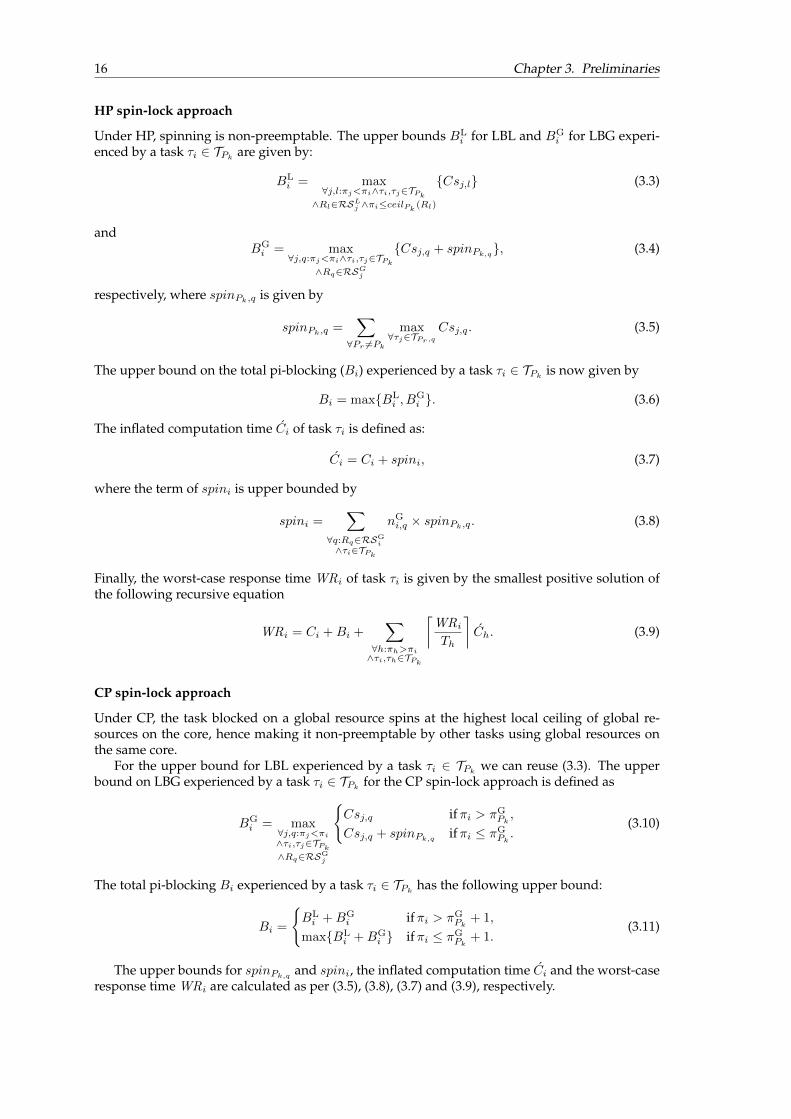
16 Chapter 3. Preliminaries
HP spin-lock approach
Under HP, spinning is non-preemptable. The upper bounds BLi for LBL and BG
i for LBG experi-enced by a task τi ∈ TPk
are given by:
BLi = max
∀j,l:πj<πi∧τi,τj∈TPk
∧Rl∈RSLj ∧πi≤ceilPk
(Rl)
{Csj,l} (3.3)
andBGi = max
∀j,q:πj<πi∧τi,τj∈TPk
∧Rq∈RSGj
{Csj,q + spinPk,q}, (3.4)
respectively, where spinPk,q is given by
spinPk,q =∑∀Pr 6=Pk
max∀τj∈TPr,q
Csj,q. (3.5)
The upper bound on the total pi-blocking (Bi) experienced by a task τi ∈ TPkis now given by
Bi = max{BLi , B
Gi }. (3.6)
The inflated computation time Ci of task τi is defined as:
Ci = Ci + spini, (3.7)
where the term of spini is upper bounded by
spini =∑
∀q:Rq∈RSGi
∧τi∈TPk
nGi,q × spinPk,q. (3.8)
Finally, the worst-case response time WRi of task τi is given by the smallest positive solution ofthe following recursive equation
WRi = Ci +Bi +∑
∀h:πh>πi∧τi,τh∈TPk
⌈WRiTh
⌉Ch. (3.9)
CP spin-lock approach
Under CP, the task blocked on a global resource spins at the highest local ceiling of global re-sources on the core, hence making it non-preemptable by other tasks using global resources onthe same core.
For the upper bound for LBL experienced by a task τi ∈ TPkwe can reuse (3.3). The upper
bound on LBG experienced by a task τi ∈ TPkfor the CP spin-lock approach is defined as
BGi = max
∀j,q:πj<πi
∧τi,τj∈TPk
∧Rq∈RSGj
{Csj,q ifπi > πG
Pk,
Csj,q + spinPk,qifπi ≤ πG
Pk.
(3.10)
The total pi-blocking Bi experienced by a task τi ∈ TPkhas the following upper bound:
Bi =
{BLi +BG
i ifπi > πGPk
+ 1,
max{BLi +BG
i } ifπi ≤ πGPk
+ 1.(3.11)
The upper bounds for spinPk,qand spini, the inflated computation time Ci and the worst-case
response time WRi are calculated as per (3.5), (3.8), (3.7) and (3.9), respectively.

3.3. System overview 17
The schedulability analysis presented in Section 3.2.3 will be extended in order to includethe effects of induced implementation overheads in Chapter 7. This concludes the recap of theFlexible Spin-Lock Model.
3.3 System overview
In this section, a brief overview of the FPGA hardware design process and the software systemused for the thesis are presented.
3.3.1 Hardware system
A brief overview of the general FPGA design process for Nios II based multiprocessor systemsand the hardware system used for this thesis are presented below.
During the preparation phase of the master thesis, to satisfy goal [I.1] of the thesis, a newhardware platform had to be selected. Since the Altera DE0 FPGA platform used for the initialimplementation [4] did not have sufficient embedded memory for instantiating 4 soft processingcores, the Altera DE2-115 FPGA board was decided as the alternative. The detailed selectionprocess for the new hardware platform was presented at the end of the preparation phase. AlteraFPGA boards allow for the use of Nios II soft processing cores in the hardware design.
The common design process to be followed for a Nios II based multiprocessor system on anAltera FPGA board is detailed in [36]. Figure 3.2 shows the design steps recommended by Altera.
FIGURE 3.2: Nios II embedded system design flow [36].
Using the recommended design process, a four processor hardware system was created to beused for implementations and measurements throughout the thesis. Figure 3.3 shows a simplifiedoverall schematic of the four core hardware system designed for the study. A brief summary ofthe salient features of the hardware design is presented in Table 3.3.

18 Chapter 3. Preliminaries
Processing core Nios II/e (32 bit RISC)#cores 4On-chip memory per core 48 kbClock frequency 50 MHz
Peripheralshardware mutex (1x)performance counter (2x)JTAG UART (1x)
TABLE 3.3: Hardware design specifications.
FIGURE 3.3: Overview of the hardware system created for the study.
3.3.2 Software system
Due to the support available for MSRP and being OSEK compliant, Erika Enterprise RTOS waschosen as the operating system of choice for the implementation of FSLM in [4]. Since this as-signment is a continuation of the previous work done in [3] and [4], the operating system choiceremains unchanged.
Figure 3.4 shows the development view of the software system used for the study. The figurepresents an overview of the components of the Erika Enterprise RTOS.
The following are a list of primary features of the software system:
• The Erika Enterprise RTOS API enables the application developer (user) to access some ofthe operating system kernel primitives. The primitives used for interacting directly withthe underlying hardware are not exposed to the user through the API and are exclusivelyhandled by the kernel.
• The kernel layer in turn uses the Hardware Abstraction Layer (HAL) provided by Altera togain access to the underlying hardware.
• In order to provide the user with the options for configuring the kernel, such as specifyingthe conformance class, mapping the tasks on to specific processors (especially for P-FPPSsystems), setting the task priorities and so on, an OIL (OSEK Implementation Language)file is used. OIL is an OSEK standard text based language that allows the user to provide atextual definition of the objects such as cpu, tasks and resources. A more detailed overviewof the OIL file is presented in Chapter 5.3.

3.3. System overview 19
FIGURE 3.4: Development view of Erika [4].
• RT-Druid [37] is a code generator plug-in for the Eclipse [38] development framework. RT-Druid is used to automatically generate the operating system files based on the user speci-fied configuration options in the OIL file during compile time.
• An executable file with the extension .elf is created at the completion of the softwaredesign process. The executable file is then programmed onto the hardware platform.
• The multi-core extension [27] of Erika Enterprise with the “multistack” configuration of the“BCC2” conformance class of the OO (OSEK OS) kernel [39] of Erika Enterprise was usedto perform the experiments in this study.
For the sake of conciseness of the report, the detailed instructions for creating the hardwareand software design are presented in Appendix A.

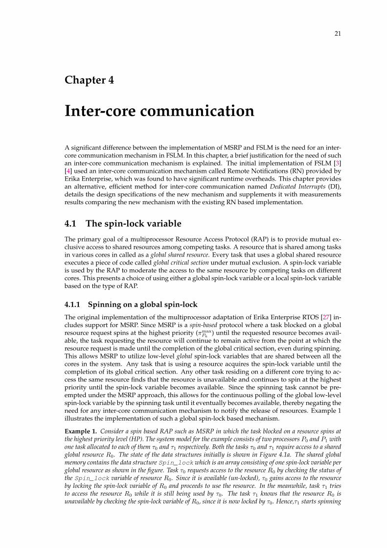
21
Chapter 4
Inter-core communication
A significant difference between the implementation of MSRP and FSLM is the need for an inter-core communication mechanism in FSLM. In this chapter, a brief justification for the need of suchan inter-core communication mechanism is explained. The initial implementation of FSLM [3][4] used an inter-core communication mechanism called Remote Notifications (RN) provided byErika Enterprise, which was found to have significant runtime overheads. This chapter providesan alternative, efficient method for inter-core communication named Dedicated Interrupts (DI),details the design specifications of the new mechanism and supplements it with measurementsresults comparing the new mechanism with the existing RN based implementation.
4.1 The spin-lock variable
The primary goal of a multiprocessor Resource Access Protocol (RAP) is to provide mutual ex-clusive access to shared resources among competing tasks. A resource that is shared among tasksin various cores in called as a global shared resource. Every task that uses a global shared resourceexecutes a piece of code called global critical section under mutual exclusion. A spin-lock variableis used by the RAP to moderate the access to the same resource by competing tasks on differentcores. This presents a choice of using either a global spin-lock variable or a local spin-lock variablebased on the type of RAP.
4.1.1 Spinning on a global spin-lock
The original implementation of the multiprocessor adaptation of Erika Enterprise RTOS [27] in-cludes support for MSRP. Since MSRP is a spin-based protocol where a task blocked on a globalresource request spins at the highest priority (πmax
Pk) until the requested resource becomes avail-
able, the task requesting the resource will continue to remain active from the point at which theresource request is made until the completion of the global critical section, even during spinning.This allows MSRP to utilize low-level global spin-lock variables that are shared between all thecores in the system. Any task that is using a resource acquires the spin-lock variable until thecompletion of its global critical section. Any other task residing on a different core trying to ac-cess the same resource finds that the resource is unavailable and continues to spin at the highestpriority until the spin-lock variable becomes available. Since the spinning task cannot be pre-empted under the MSRP approach, this allows for the continuous polling of the global low-levelspin-lock variable by the spinning task until it eventually becomes available, thereby negating theneed for any inter-core communication mechanism to notify the release of resources. Example 1illustrates the implementation of such a global spin-lock based mechanism.
Example 1. Consider a spin based RAP such as MSRP in which the task blocked on a resource spins atthe highest priority level (HP). The system model for the example consists of two processors P0 and P1 withone task allocated to each of them τ0 and τ1 respectively. Both the tasks τ0 and τ1 require access to a sharedglobal resource R0. The state of the data structures initially is shown in Figure 4.1a. The shared globalmemory contains the data structure Spin_lock which is an array consisting of one spin-lock variable perglobal resource as shown in the figure. Task τ0 requests access to the resource R0 by checking the status ofthe Spin_lock variable of resource R0. Since it is available (un-locked), τ0 gains access to the resourceby locking the spin-lock variable of R0 and proceeds to use the resource. In the meanwhile, task τ1 triesto access the resource R0 while it is still being used by τ0. The task τ1 knows that the resource R0 isunavailable by checking the spin-lock variable of R0, since it is now locked by τ0. Hence,τ1 starts spinning
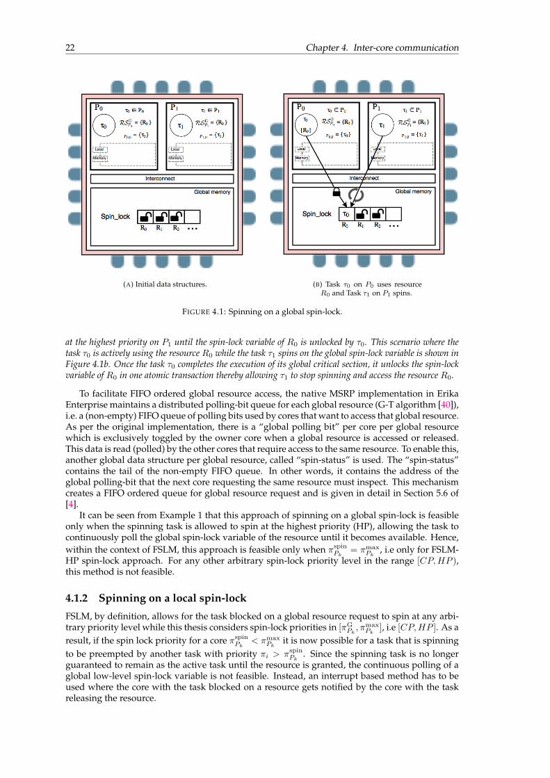
22 Chapter 4. Inter-core communication
(A) Initial data structures. (B) Task τ0 on P0 uses resourceR0 and Task τ1 on P1 spins.
FIGURE 4.1: Spinning on a global spin-lock.
at the highest priority on P1 until the spin-lock variable of R0 is unlocked by τ0. This scenario where thetask τ0 is actively using the resource R0 while the task τ1 spins on the global spin-lock variable is shown inFigure 4.1b. Once the task τ0 completes the execution of its global critical section, it unlocks the spin-lockvariable of R0 in one atomic transaction thereby allowing τ1 to stop spinning and access the resource R0.
To facilitate FIFO ordered global resource access, the native MSRP implementation in ErikaEnterprise maintains a distributed polling-bit queue for each global resource (G-T algorithm [40]),i.e. a (non-empty) FIFO queue of polling bits used by cores that want to access that global resource.As per the original implementation, there is a “global polling bit” per core per global resourcewhich is exclusively toggled by the owner core when a global resource is accessed or released.This data is read (polled) by the other cores that require access to the same resource. To enable this,another global data structure per global resource, called “spin-status” is used. The “spin-status”contains the tail of the non-empty FIFO queue. In other words, it contains the address of theglobal polling-bit that the next core requesting the same resource must inspect. This mechanismcreates a FIFO ordered queue for global resource request and is given in detail in Section 5.6 of[4].
It can be seen from Example 1 that this approach of spinning on a global spin-lock is feasibleonly when the spinning task is allowed to spin at the highest priority (HP), allowing the task tocontinuously poll the global spin-lock variable of the resource until it becomes available. Hence,within the context of FSLM, this approach is feasible only when πspin
Pk= πmax
Pk, i.e only for FSLM-
HP spin-lock approach. For any other arbitrary spin-lock priority level in the range [CP,HP ),this method is not feasible.
4.1.2 Spinning on a local spin-lock
FSLM, by definition, allows for the task blocked on a global resource request to spin at any arbi-trary priority level while this thesis considers spin-lock priorities in [πG
Pk, πmaxPk
], i.e [CP,HP ]. As aresult, if the spin lock priority for a core πspin
Pk< πmax
Pkit is now possible for a task that is spinning
to be preempted by another task with priority πi > πspinPk
. Since the spinning task is no longerguaranteed to remain as the active task until the resource is granted, the continuous polling of aglobal low-level spin-lock variable is not feasible. Instead, an interrupt based method has to beused where the core with the task blocked on a resource gets notified by the core with the taskreleasing the resource.

4.1. The spin-lock variable 23
The initial implementation of FSLM performed in [3] [4], utilized the Erika Enterprise originalimplementation of MSRP as the basis on which changes were made to include support for FSLM.The detailed list of changes performed to the original implementation can be found in Chapter 8of [4]. However, for the sake of completeness of the report and to aid the reader in comprehendingthe motivation for the addition of an inter-core communication mechanism, the primary designchoices made in [4] are detailed in this part of the report. In order to add support for spinning atarbitrary priority levels, the following major changes were made to the original Erika Enterprisein [4]:
1. Spinning on a local spin-lock variable instead of global spin-lock variable.
2. Notification of resource release by the releasing task to a blocked task in a remote core whenapplicable.
Implementation of a local-spin lock method in FSLM
Although it is termed as spinning on a local spin-lock variable, in order to co-ordinate the resourceaccess among tasks residing in multiple cores, it is essential to use global data structures. Thefollowing global data structures were used along with a local Spin_lock variable (one per core)in the initial implementation of FSLM [3] [4]:
• ResourceQ - A 2-dimensional array with n × m entries where n denotes the number ofglobal resources in the system and m denotes the number of processors in the system.
• TailQ - A single dimensional array consisting of n entries where n denotes the number ofglobal resources in the system. Denotes the current spin status of the resources by pointingto the tail of the ResourceQ data structure.
The resource requests and accesses under the FSLM implementation on Erika Enterprise are han-dled as follows:
1. Contents of ResourceQ[Rq][Pk] are initialized to 0xa0 at startup, denoting that Pk is notactively using or has pending requests for resource Rq .
2. Contents of TailQ[Rq] are initialized pointing to the address of ResourceQ[Rq][P0].
3. When a task on a core Pk tries to access a resource Rq , it checks for the contents of theaddress pointed to by TailQ[Rq]. The resource is available if the contents of the addresspointed to by TailQ[Rq] is 0xa0 and unavailable otherwise.
4. If the resource is available, the task stores its TaskID in ResourceQ[Rq][Pk] denoting thatit is currently using the resource. It also sets TailQ[Rq] to point to ResourceQ[Rq][Pk].Any task from a different core Pl trying to access the same resource now will know that theresource is unavailable because the contents of the address pointed to by TailQ[Rq] willnow be the TaskID of the task using the resource instead of 0xa0.
5. If the resource is unavailable, the task from core Pl locks its local Spin_lock variable. Italso updates the value at the address pointed to by TailQ[Rq], i.e ResourceQ[Rq][Pk]with its own TaskID. This is the location the core releasing the resource will check to knowwhich core to notify upon release. The task also updates the contents of ResourceQ[Rq][Pl]with its TaskID and then updates TailQ[Rq] to point to ResourceQ[Rq][Pl].
6. During resource release, the core Pk releasing the resource checks ResourceQ[Rq][Pk].If the contents are equal to its TaskID, then the core does not have to notify any other core.Otherwise, the TaskID is used to identify the core to which a notification has to be sent.
7. Upon receipt of a notification (Remote Notification)1 in core Pl, the Interrupt Service Rou-tine (ISR) resets the value of the Spin_lock variable and the task on core Pl resumes re-source access. In case the spinning task has been preempted by higher priority task, the RNcontains the TaskID of the requesting task so that context switch can be facilitated.
1Remote Notifications are a shared memory and interrupt based inter-core communication mechanism provided bythe Erika Enterprise kernel, explained further in Section 4.2

24 Chapter 4. Inter-core communication
(A) Initial data-structures. (B) Task τ1 on P1 uses the re-source R0.
FIGURE 4.2: Spinning on a local spin-lock.
(A) Task τ0 on P0 spins. (B) Task τ1 on P1 releases re-source R0 and Task τ0 on P0 uses
the resource R0.
FIGURE 4.3: Spinning on a local spin-lock.
Example 2. The example illustrates the functioning of the initial implementation of FSLM as describedin Section 4.1.2. The system model for the example consists of two processors P0 and P1 with one taskallocated to each of them τ0 and τ1 respectively. Both the tasks τ0 and τ1 require access to a shared globalresource R0. Figure 4.2a shows the initial data structures during startup. Figure 4.2b shows the status ofthe data structures when the task τ1 on processor P1 tries to access resourceR0. The task initially checks thecontent of the address pointed to by TailQ[R0], i.e ResourceQ[R0][P0] in this case. Since initially,the contents of ResourceQ[R0][P0] is 0xa0, it signifies that the resource R0 is available and the taskτ1 acquires the resource. The task τ1 now updates the value of ResourceQ[R0][P1] with its TaskIDand also changes the value of TailQ[R0] to point to ResourceQ[R0][P1].
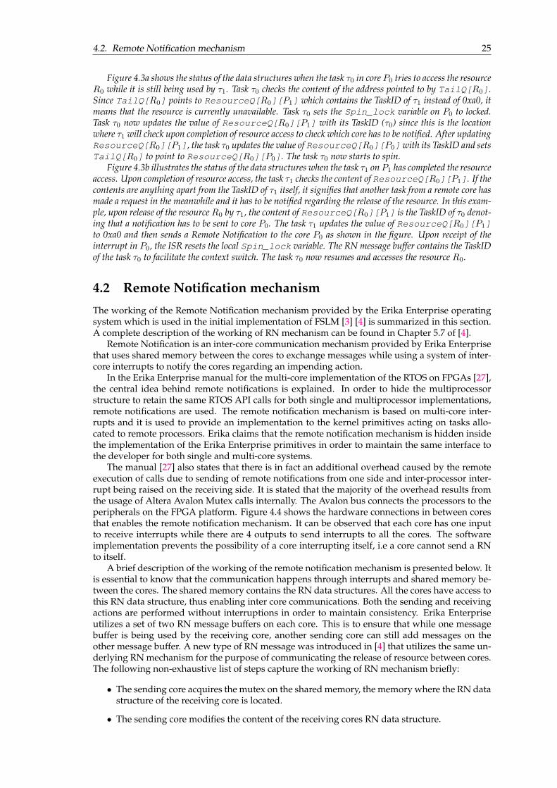
4.2. Remote Notification mechanism 25
Figure 4.3a shows the status of the data structures when the task τ0 in core P0 tries to access the resourceR0 while it is still being used by τ1. Task τ0 checks the content of the address pointed to by TailQ[R0].Since TailQ[R0] points to ResourceQ[R0][P1] which contains the TaskID of τ1 instead of 0xa0, itmeans that the resource is currently unavailable. Task τ0 sets the Spin_lock variable on P0 to locked.Task τ0 now updates the value of ResourceQ[R0][P1] with its TaskID (τ0) since this is the locationwhere τ1 will check upon completion of resource access to check which core has to be notified. After updatingResourceQ[R0][P1], the task τ0 updates the value of ResourceQ[R0][P0]with its TaskID and setsTailQ[R0] to point to ResourceQ[R0][P0]. The task τ0 now starts to spin.
Figure 4.3b illustrates the status of the data structures when the task τ1 onP1 has completed the resourceaccess. Upon completion of resource access, the task τ1 checks the content of ResourceQ[R0][P1]. If thecontents are anything apart from the TaskID of τ1 itself, it signifies that another task from a remote core hasmade a request in the meanwhile and it has to be notified regarding the release of the resource. In this exam-ple, upon release of the resourceR0 by τ1, the content of ResourceQ[R0][P1] is the TaskID of τ0 denot-ing that a notification has to be sent to core P0. The task τ1 updates the value of ResourceQ[R0][P1]to 0xa0 and then sends a Remote Notification to the core P0 as shown in the figure. Upon receipt of theinterrupt in P0, the ISR resets the local Spin_lock variable. The RN message buffer contains the TaskIDof the task τ0 to facilitate the context switch. The task τ0 now resumes and accesses the resource R0.
4.2 Remote Notification mechanism
The working of the Remote Notification mechanism provided by the Erika Enterprise operatingsystem which is used in the initial implementation of FSLM [3] [4] is summarized in this section.A complete description of the working of RN mechanism can be found in Chapter 5.7 of [4].
Remote Notification is an inter-core communication mechanism provided by Erika Enterprisethat uses shared memory between the cores to exchange messages while using a system of inter-core interrupts to notify the cores regarding an impending action.
In the Erika Enterprise manual for the multi-core implementation of the RTOS on FPGAs [27],the central idea behind remote notifications is explained. In order to hide the multiprocessorstructure to retain the same RTOS API calls for both single and multiprocessor implementations,remote notifications are used. The remote notification mechanism is based on multi-core inter-rupts and it is used to provide an implementation to the kernel primitives acting on tasks allo-cated to remote processors. Erika claims that the remote notification mechanism is hidden insidethe implementation of the Erika Enterprise primitives in order to maintain the same interface tothe developer for both single and multi-core systems.
The manual [27] also states that there is in fact an additional overhead caused by the remoteexecution of calls due to sending of remote notifications from one side and inter-processor inter-rupt being raised on the receiving side. It is stated that the majority of the overhead results fromthe usage of Altera Avalon Mutex calls internally. The Avalon bus connects the processors to theperipherals on the FPGA platform. Figure 4.4 shows the hardware connections in between coresthat enables the remote notification mechanism. It can be observed that each core has one inputto receive interrupts while there are 4 outputs to send interrupts to all the cores. The softwareimplementation prevents the possibility of a core interrupting itself, i.e a core cannot send a RNto itself.
A brief description of the working of the remote notification mechanism is presented below. Itis essential to know that the communication happens through interrupts and shared memory be-tween the cores. The shared memory contains the RN data structures. All the cores have access tothis RN data structure, thus enabling inter core communications. Both the sending and receivingactions are performed without interruptions in order to maintain consistency. Erika Enterpriseutilizes a set of two RN message buffers on each core. This is to ensure that while one messagebuffer is being used by the receiving core, another sending core can still add messages on theother message buffer. A new type of RN message was introduced in [4] that utilizes the same un-derlying RN mechanism for the purpose of communicating the release of resource between cores.The following non-exhaustive list of steps capture the working of RN mechanism briefly:
• The sending core acquires the mutex on the shared memory, the memory where the RN datastructure of the receiving core is located.
• The sending core modifies the content of the receiving cores RN data structure.

26 Chapter 4. Inter-core communication
FIGURE 4.4: Inter core interrupts hardware connection for Remote Notifications[4].
• The sending core releases the lock.
• The sending core raises an interrupt via the interconnect on the receiving core.
• The receiving core, upon receiving the interrupt, acquires the lock on its RN data structure.
• The core reads the message and releases the lock.
• The receiving core executes the RN message.
The above operations are accomplished using the functions EE_rn_send(), EE_rn_handler()and EE_rn_execute() implemented in the Erika kernel and declared in the file ee_rn_internal.h.
4.3 Dedicated Interrupts
One of the primary goals of this thesis is to implement an inter-core communication mechanismthat reduces the runtime overheads incurred due to the existing Remote Notification mechanism.This section details the motivation for such a system, the design considerations and the details ofthe implementation. This new inter-core communication mechanism that is designed as a replace-ment for the RN mechanism is termed as Dedicated Interrupts (DI) since it is no longer a generalpurpose inter-core communication system as intended by the original implementation of ErikaEnterprise, but merely a system of interrupts dedicated to indicate the release of resources in themultiprocessor RAP context.
4.3.1 Motivation for Dedicated Interrupts
The RN mechanism as explained in Section 4.2 utilizes both a system of interrupts and sharedmemory to facilitate inter-core communication. The use of shared memory for communicationrequires mutual exclusive access to the shared RN data structures giving rise to a significant run-time overhead each time such a notification is sent or received. In this section, the decision toreplace the RN mechanism with a purely interrupt based notification mechanism is motivated.
Remote Notifications offer a generic interface for communicating between the cores. The na-ture of these communicated messages can vary depending upon the application that uses theErika Enterprise kernel. In the original implementation of the Erika Enterprise, a total of 6 RN
4.3. Dedicated Interrupts 27
types are defined and supported. Listing 4.1 shows the types of RN supported by the originalErika Enterprise. For example, the RN message type EE_RN_TASK is used for the remote activa-tion of a task on a core from a different core.
1 /* Notification types */2 #ifdef __RN_COUNTER__3 #define EE_RN_COUNTER 14 #endif5
6 #ifdef __RN_EVENT__7 #define EE_RN_EVENT 28 #endif9
10 #ifdef __RN_TASK__11 #define EE_RN_TASK 412 #endif13
14 #ifdef __RN_FUNC__15 #define EE_RN_FUNC 816 #endif17
18 #ifdef __RN_BIND__19 #define EE_RN_BIND 1620 #endif21
22 #ifdef __RN_UNBIND__23 #define EE_RN_UNBIND 3224 #endif
LISTING 4.1: RN message types in the original Erika Enterprise.
The support for each type of RN is included or excluded from the kernel based on the kerneltype and conformance class requirements of the real-time application. In the initial implemen-tation of FSLM [4] it was found that for an application based on P-FPPS, while using the multi-core extension [27] of the “multistack” configuration of the “BCC2” conformance class of the OO(OSEK OS) kernel [39] of Erika Enterprise, none of the six original RN types are required to beenabled in the implementation. Hence, the initial implementation of FSLM in Erika Enterprise [3][4] introduces a new type of RN message, RN_ReleaseResource used exclusively for notifyingthe release of a resource to another remote core.
The RN data structures consist of a control part and a message part. To leverage the existingframework of RN in [4], the new type of RN created (RN_ReleaseResource) uses the controland message parts of the message according to the rules of RN mechanism, detailed in Section5.7 of [4]. The only content of the message part is the TaskID of the task on the remote core thathas to be notified. This information is retrieved from the ResourceQ[Rq][Pk] as explained inSection 4.1.2. The content is then used by the receiving core to perform the context-switch asrequired if the required task has been preempted while spinning by a higher priority τi ∈ TPk
task with a priority πi > πspinPk
.Lemma 12 in [2] proves that there can only be at most one task on a processor Pk with a pending
request to a global resource at any time if {πspinPk≥ πG
Pk}. This indicates that upon receipt of a RN,
the ISR of the receiving core inherently is made aware of a resource release for one of its spinningtasks that has either been preempted by a higher priority task or is still actively spinning at πspin
Pk.
This motivates the removal of the usage of the RN data structures altogether and to merely usea simple inter-core hardware interrupt to signal the release of a resource for spin-lock prioritiesin [CP, HP]. The removal of shared memory based RN buffers is expected to significantly reducethe runtime overheads associated with each resource access and release in the implementation ofFSLM.
The rest of this section focuses on the design, implementation and verification of a dedicatedinterrupt mechanism replacing the RN mechanism in the implementation of FSLM.
4.3.2 Design
The high level functional requirements for the Dedicated Interrupts mechanism are presented inthis section. The invariant and predicates that must hold for the DI mechanism are also definedin this section.
Requirements
1. Sending the interrupt

28 Chapter 4. Inter-core communication
a) CPU ID of the receiving core must be determined by the sending core from the TaskIDof the target task.
b) An inter-core interrupt is raised on the corresponding target core by the sending core.
c) The target core should never be the same as the sending core.
d) The sending core must execute the interrupt sender function uninterruptedly.
2. Receiving the interrupt
a) Upon receiving an inter-core interrupt, the interrupt handler on the receiving core mustidentify the requesting task and the resource on which the task was blocked.
b) System ceiling on the receiving core is set to non-preemptable level.
c) The local spin lock variable must be reset to unlocked on the receiving core.
d) Context switch must happen if the requesting task was preempted while spinning.
Invariant and Predicates
Invariant 1. During startup, on each core in the system, the spin-lock is unlocked, which impliesthat the number of received DIs is equal to the number of processed DIs.
Predicate 1. A core will receive a DI only if the local spin-lock variable is locked.
Predicate 2. The number of received DIs on a core can at most be only one greater than thenumber of processed DIs on the core, for spin-lock priorities in [CP, HP].
4.3.3 Implementation
The function names used for sending and handling inter-core communications in Remote No-tifications (RN) are changed for the implementation of the Dedicated Interrupts mechanism al-though parts of the implementation are re-used. The following three functions were defined tofacilitate the Dedicated Interrupts mechanism:
1. EE_di_send() - Used to send a dedicated interrupt signifying the release of a global re-source to a remote core.
2. EE_di_handler() - Used as the Interrupt Service Routine on the receiving core to handlethe incoming dedicated interrupt.
3. EE_di_execute() - Used to perform the required action when a dedicated interrupt isreceived.
Changes to EE_oo_GetResource() and EE_oo_ReleaseResource()
The implementation of dedicated interrupt mechanism for signaling resource release will nolonger involve shared memory based messages as in case of RN mechanism. Hence, the TaskIDof the task spinning on a remote core blocked on a resource cannot be communicated using theRN shared data structures. Additional changes have to be made upon each resource access andrelease to locally maintain a record of the TaskID of the task requesting and releasing the globalresource.
The functions EE_oo_GetResource() and EE_oo_ReleaseResource() are used to ac-cess and release a resource respectively.
FIGURE 4.5: Calls graph for the function EE_oo_GetResource().
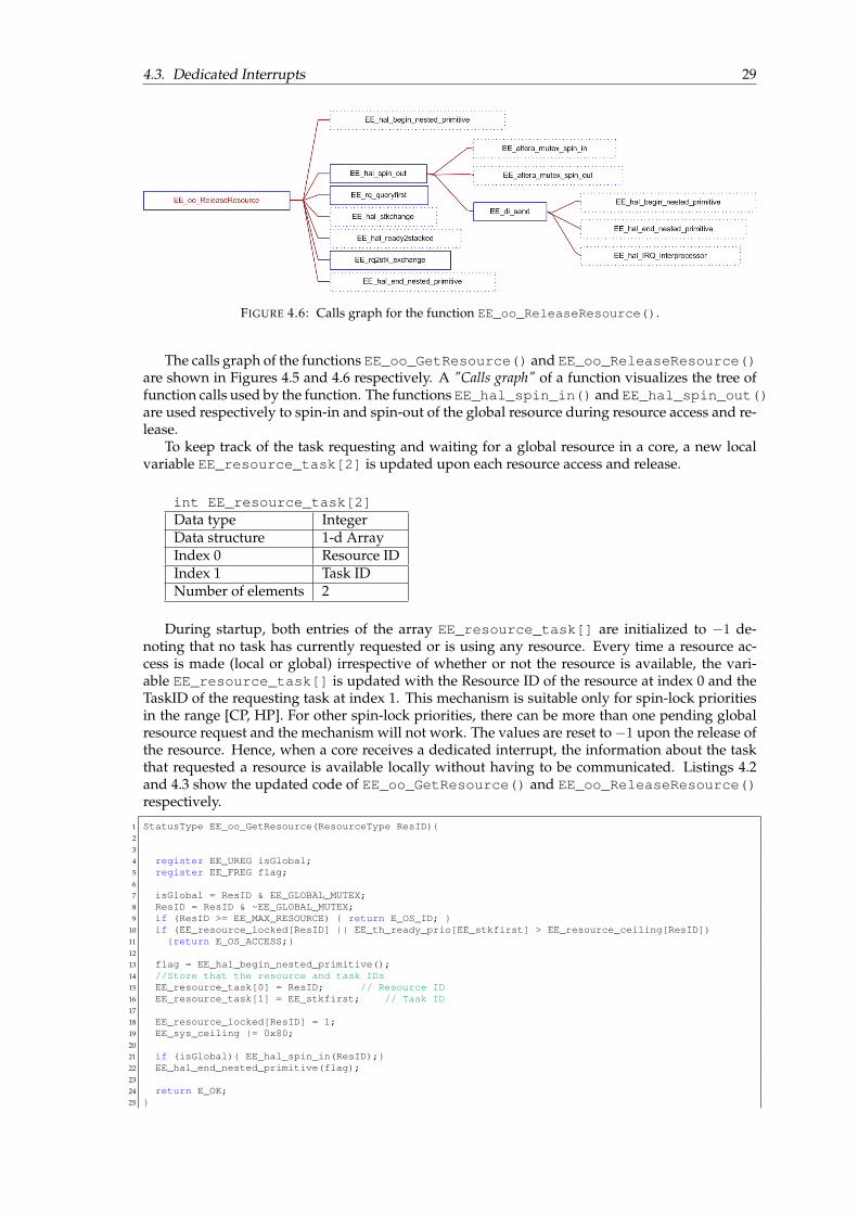
4.3. Dedicated Interrupts 29
FIGURE 4.6: Calls graph for the function EE_oo_ReleaseResource().
The calls graph of the functions EE_oo_GetResource() and EE_oo_ReleaseResource()are shown in Figures 4.5 and 4.6 respectively. A "Calls graph" of a function visualizes the tree offunction calls used by the function. The functions EE_hal_spin_in() and EE_hal_spin_out()are used respectively to spin-in and spin-out of the global resource during resource access and re-lease.
To keep track of the task requesting and waiting for a global resource in a core, a new localvariable EE_resource_task[2] is updated upon each resource access and release.
int EE_resource_task[2]Data type IntegerData structure 1-d ArrayIndex 0 Resource IDIndex 1 Task IDNumber of elements 2
During startup, both entries of the array EE_resource_task[] are initialized to −1 de-noting that no task has currently requested or is using any resource. Every time a resource ac-cess is made (local or global) irrespective of whether or not the resource is available, the vari-able EE_resource_task[] is updated with the Resource ID of the resource at index 0 and theTaskID of the requesting task at index 1. This mechanism is suitable only for spin-lock prioritiesin the range [CP, HP]. For other spin-lock priorities, there can be more than one pending globalresource request and the mechanism will not work. The values are reset to −1 upon the release ofthe resource. Hence, when a core receives a dedicated interrupt, the information about the taskthat requested a resource is available locally without having to be communicated. Listings 4.2and 4.3 show the updated code of EE_oo_GetResource() and EE_oo_ReleaseResource()respectively.
1 StatusType EE_oo_GetResource(ResourceType ResID){2
3
4 register EE_UREG isGlobal;5 register EE_FREG flag;6
7 isGlobal = ResID & EE_GLOBAL_MUTEX;8 ResID = ResID & ~EE_GLOBAL_MUTEX;9 if (ResID >= EE_MAX_RESOURCE) { return E_OS_ID; }
10 if (EE_resource_locked[ResID] || EE_th_ready_prio[EE_stkfirst] > EE_resource_ceiling[ResID])11 {return E_OS_ACCESS;}12
13 flag = EE_hal_begin_nested_primitive();14 //Store that the resource and task IDs15 EE_resource_task[0] = ResID; // Resource ID16 EE_resource_task[1] = EE_stkfirst; // Task ID17
18 EE_resource_locked[ResID] = 1;19 EE_sys_ceiling |= 0x80;20
21 if (isGlobal){ EE_hal_spin_in(ResID);}22 EE_hal_end_nested_primitive(flag);23
24 return E_OK;25 }

30 Chapter 4. Inter-core communication
LISTING 4.2: Updated code of EE_oo_GetResource().
1 StatusType EE_oo_ReleaseResource(ResourceType ResID){2 EE_TID rq, current;3 EE_UREG isGlobal;4 register EE_FREG flag;5 extern int Preemption_took_place;6
7 isGlobal = ResID & EE_GLOBAL_MUTEX;8 ResID = ResID & ~EE_GLOBAL_MUTEX;9
10 if (ResID >= EE_MAX_RESOURCE) { return E_OS_ID;}11 current = EE_stkfirst;12 if (EE_th_ready_prio[current] > EE_resource_ceiling[ResID]) {return E_OS_ACCESS;}13
14 flag = EE_hal_begin_nested_primitive();15 //Indicate that the task has released the resource16 EE_resource_locked[ResID] = 0;17 EE_resource_task[0] = -1;18 EE_resource_task[1] = -1;19
20 if (isGlobal) EE_hal_spin_out(ResID);21 rq = EE_rq_queryfirst();22 EE_sys_ceiling &=~0x80;23 EE_sys_ceiling &=~EE_th_spin_prio[EE_stkfirst];24 EE_sys_ceiling |= EE_th_dispatch_prio[EE_stkfirst];25
26 if(Preemption_took_place==1){27 Preemption_took_place=0;28 if(EE_th_ready_prio[EE_stkfirst]>= EE_th_ready_prio[rq] || rq == EE_NIL){29 EE_hal_stkchange(EE_stkfirst);30 }31 }32
33 if (rq != EE_NIL) {34 if (EE_sys_ceiling < EE_th_ready_prio[rq]) {35 EE_th_status[current] = READY;36 EE_th_status[rq] = RUNNING;37 EE_sys_ceiling |= EE_th_dispatch_prio[rq];38
39
40 EE_hal_ready2stacked(EE_rq2stk_exchange());41 }42 }43
44 EE_hal_end_nested_primitive(flag);45 return E_OK;46 }
LISTING 4.3: Updated code of EE_oo_ReleaseResource().
Sending core
The implementation of EE_di_send() function is detailed here. The EE_di_send() functionis used for sending an interrupt to a remote core Py from a core Px (x 6= y) indicating the releaseof a global resource Rq . The function prototype is as follows:
int EE_di_send(EE_TID rtid)
Argument 1 rtid TaskID of the remote task that needs to be notifiedregarding the resource release.
Returns 0 Success1 Otherwise
Figure 4.7a illustrates the execution flow of the function EE_di_send(). The functions calledby EE_di_send(), i.e the calls graph is shown in Figure 4.7b. It can be observed that there areno shared data structures and mutual exclusion involved in sending an interrupt. The function,as can be seen from Figure 4.7a, is executed with incoming interrupts disabled.
The function EE_di_send() is called during resource release from EE_hal_spin_out()function as shown in Figure 4.6. The pseudo code and the C-code of the function EE_di_send()are given in Listings 4.4 and 4.5 respectively.

4.3. Dedicated Interrupts 31
1 EE_di_send(TaskID of the remote task){2 Disable Interrupts3
4 Find the CPU to which the remote task with TaskID belongs5 If remote CPU is the same as current CPU{6 Enable Interrupts7 Return to the calling function8 }9 else{
10 Send Inter-core interrupt to the remote CPU11 }12 Enable Interrupts13 }
LISTING 4.4: Pseudo code for EE_di_send() function.
1 int EE_di_send(EE_TYPERN rtid){2
3 register EE_UINT8 cpu;4 register EE_FREG flag;5
6 flag = EE_hal_begin_nested_primitive();7 //Find the core to which the remote task belongs8 cpu = EE_rn_cpu[rtid];9
10 if (cpu == EE_CURRENTCPU) {11 // THIS SHOULD NEVER HAPPEN Local notification not allowed12 EE_hal_end_nested_primitive(flag);13 return 1;14 } else {15 EE_hal_IRQ_interprocessor(cpu);16 }17 EE_hal_end_nested_primitive(flag);18
19 return 0;20 }
LISTING 4.5: C-code for EE_di_send() function.
(A) Flow chart ofEE_di_send().
(B) Calls graph ofEE_di_send() function.
FIGURE 4.7: The EE_di_send() function.
Receiving core
The function EE_di_handler() is registered on each core as the interrupt handler function.The input interrupt line for every core is specified in the CONF.OIL file and it is assigned to thefunction EE_nios2_IIRQ_handler() during startup. Hence it serves as the ISR associatedwith all the dedicated inter-core interrupt lines shown in Figure 4.4.
void EE_di_handler()Arguments NoneReturns void
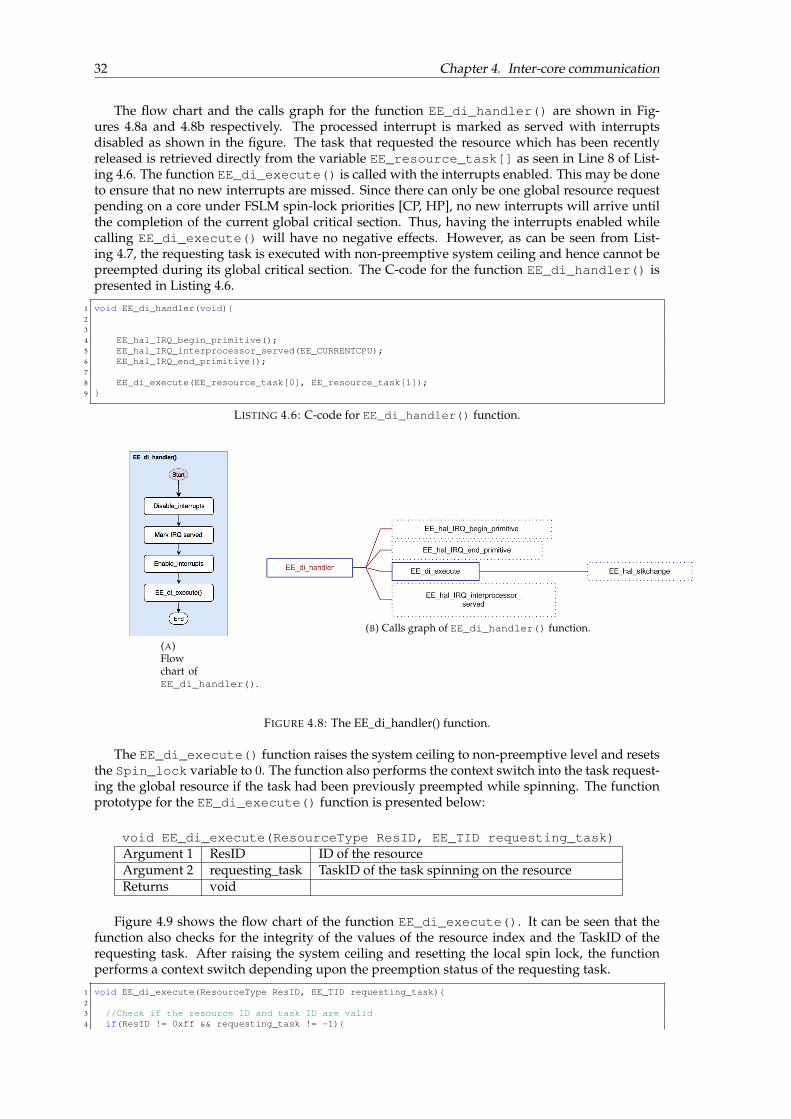
32 Chapter 4. Inter-core communication
The flow chart and the calls graph for the function EE_di_handler() are shown in Fig-ures 4.8a and 4.8b respectively. The processed interrupt is marked as served with interruptsdisabled as shown in the figure. The task that requested the resource which has been recentlyreleased is retrieved directly from the variable EE_resource_task[] as seen in Line 8 of List-ing 4.6. The function EE_di_execute() is called with the interrupts enabled. This may be doneto ensure that no new interrupts are missed. Since there can only be one global resource requestpending on a core under FSLM spin-lock priorities [CP, HP], no new interrupts will arrive untilthe completion of the current global critical section. Thus, having the interrupts enabled whilecalling EE_di_execute() will have no negative effects. However, as can be seen from List-ing 4.7, the requesting task is executed with non-preemptive system ceiling and hence cannot bepreempted during its global critical section. The C-code for the function EE_di_handler() ispresented in Listing 4.6.
1 void EE_di_handler(void){2
3
4 EE_hal_IRQ_begin_primitive();5 EE_hal_IRQ_interprocessor_served(EE_CURRENTCPU);6 EE_hal_IRQ_end_primitive();7
8 EE_di_execute(EE_resource_task[0], EE_resource_task[1]);9 }
LISTING 4.6: C-code for EE_di_handler() function.
(A)Flowchart ofEE_di_handler().
(B) Calls graph of EE_di_handler() function.
FIGURE 4.8: The EE_di_handler() function.
The EE_di_execute() function raises the system ceiling to non-preemptive level and resetsthe Spin_lock variable to 0. The function also performs the context switch into the task request-ing the global resource if the task had been previously preempted while spinning. The functionprototype for the EE_di_execute() function is presented below:
void EE_di_execute(ResourceType ResID, EE_TID requesting_task)Argument 1 ResID ID of the resourceArgument 2 requesting_task TaskID of the task spinning on the resourceReturns void
Figure 4.9 shows the flow chart of the function EE_di_execute(). It can be seen that thefunction also checks for the integrity of the values of the resource index and the TaskID of therequesting task. After raising the system ceiling and resetting the local spin lock, the functionperforms a context switch depending upon the preemption status of the requesting task.
1 void EE_di_execute(ResourceType ResID, EE_TID requesting_task){2
3 //Check if the resource ID and task ID are valid4 if(ResID != 0xff && requesting_task != -1){

4.3. Dedicated Interrupts 33
5 extern int spin_lock;6 extern int Preemption_took_place;7 EE_sys_ceiling |= 0x80;8 spin_lock = 0;9
10 //Check if the requesting task is at the top of the stack11 if( requesting_task != EE_stkfirst){12 Preemption_took_place = 1;13 EE_hal_stkchange(requesting_task);14 }15 }16 }
LISTING 4.7: C-code for EE_di_execute() function.
FIGURE 4.9: Flow chart of EE_di_execute().
4.3.4 Verification
The component functions of the Dedicated Interrupts mechanism were constructed based on theexisting Remote Notification method offered by Erika Enterprise. The set of changes in DI whencompared to RN are investigated, and the validity of the changes are established by means ofsimple textual proofs and functional verification.
Figures 4.10a and 4.10b show the flow charts of EE_rn_send() and EE_rn_handler()functions respectively while also highlighting using extended boxes, the parts that are not in-cluded in the DI method. This figure is for illustration purposes only. The function call toEE_di_execute() in DI handler occurs at the end (Figure 4.8a) unlike in RN. The significantdifferences between the two methods in terms of implementation can be summarized as follows:
1. RN uses the shared memory based RN message buffers for communicating the additionalinformation about the nature of the interrupt. DI does not use shared memory since it is nota generic communication method like RN.
2. RN supports multiple pending requests while processing in order to allow for differenttypes of actions. Since DI is dedicated only to signal resource release, the implementation isonly required to handle at most one incoming interrupt at a time (See proof for Predicate 2).
Check Invariant and Predicates
The design is validated by checking the invariant and predicates defined in Sections 4.3.2.

34 Chapter 4. Inter-core communication
(A) Flow chart ofEE_rn_send().
(B) Flow chart ofEE_rn_handler().
FIGURE 4.10: Remote Notification component functions with the difference be-tween DI and RN highlighted.
Invariant 1. During startup, on each core in the system, the spin-lock is unlocked, which implies that thenumber of received DIs is equal to the number of processed DIs.By design, DIs can be sent only from within the EE_oo_ReleaseResource() function.The function EE_oo_StartOS that is executed during the system startup does not containcalls to the EE_oo_ReleaseResource() function and hence, during startup, the numberof received and processed DIs on all cores in the system is equal to zero.
Predicate 1. A core will receive a DI only if the local spin-lock variable is locked.Upon every global resource request, the only place where the variable spin_lock on thecore is set to 1 if the requested resource is found to be unavailable is within the EE_hal_spin_in() function. Following the setting of the spin-lock, the TailQ[] is updated. Thismechanism as described in Figure 4.3a is responsible for indicating the target core to thecore holding the resource for sending a DI. In the function EE_hal_spin_in(), the twosteps occur in sequence, thereby denoting a bi-implication relation between the setting ofthe spin-lock and expecting a DI.
Predicate 2. The number of received DIs on a core can at most be only one greater than the number ofprocessed DIs on the core, for spin-lock priorities in [CP, HP].A proof by contradiction can be provided to establish this predicate. Assume that the num-ber of received (unprocessed) Dedicated Interrupts (DI) is 2 or more greater than the numberof processed DIs on a core with spin-lock priority in [CP, HP]. This signifies that either oneremote core has sent 2 or more DIs to the receiving core (Case (i)) or two or more remote

4.3. Dedicated Interrupts 35
cores have sent DIs to the receiving core (Case (ii)). The two cases are examined further:Case (i) Assume that 2 or more DIs are sent from the same core. For a given global resourceRq , this can only happen if the sending core releases Rq , accesses it again and subsequentlyreleases it for the second time. However, since the resource requests are FIFO ordered, whenthe sending core releases Rq for the first time and sends a DI to the receiving core, it impliesthat before the sending core can access Rq again, it can only occur in the ResourceQ af-ter the receiving core. For 2 or more different global resources released consecutively bythe sending core, the receiving core can at most occur in only one of the ResourceQ sinceLemma 12 in [2] proves that there can only be at most one task on a processor with a pend-ing request to a global resource at any time for spin-lock priorities CP and above. Thus, incombination with predicate 1, it can be observed that a new DI cannot be expected until theprevious DI has been processed and the spin-lock variable is locked again.Case (ii) Assume 2 or more cores send DIs to the same core simultaneously. From Lemma 12of [2], it is clear that all the sending cores must send DIs for the same global resource. This isimpossible since by definition, at any given instant, at most only one task in the system canaccess a resource (mutual-exclusion). Also, resource access is carried out non-preemptively,thereby making the scenario where multiple cores send DIs regarding the same resource tothe same core impossible.This predicate establishes that at any given instant, there can never be 2 or more pend-ing interrupts notifying the release of resources. In other words, under the condition thatthe spin-lock priority is in [CP, HP], a DI can never occur while a core is already process-ing a previously received DI. This serves to justify the removal of the check present in RNmechanism for a new interrupt while a core is handling a previously received interrupt asillustrated in Figure 4.10b.
Functional verification
A functional verification of the newly implemented Dedicated Interrupts mechanism was alsoperformed. The test environment used for the functional verification is detailed below:
Test environmentNumber of cores 3Number of tasks 4Number of global resources 1
Task propertiesTask ID Core Priority Resource Peripherals
Task 0 (τ0) 1 1 R0- Button 0 (activation)- LED 0
Task 1 (τ1) 1 2 - - Button 1 (activation)- LED 1
Task 2 (τ2) 1 3 - - Button 2 (activation)- LED 2
Task 3 (τ3) 2 1 R0- Button 3 (activation)- LED 3
Spin-lock prioritiesCore 0 (P0) - Core 1 (P1) 2 Core 2 (P2) 1
All the tasks are manually triggered using peripheral I/O buttons. The task τ0 with resourceaccess consists of a long global critical section (gcs) preceded and succeeded by a non-critical section(ncs) whereas task τ3 only consists of a long gcs. Blinking of respective LEDs indicates the execu-tion of tasks with a faster blinking blinking rates denoting the execution of gcs. All ncs and gcslengths are sufficiently increased to enable manual monitoring of the execution status of the tasks.The test cases that were executed to functionally verify the DI mechanism are listed in Table 4.1.
36 Chapter 4. Inter-core communication
Test case description Expected result Result
Establish that all tasks work under no contention,1. Press button 0 - wait for the task to complete (τ0 on core 1),2. Press button 1 - wait for the task to complete (τ1 on core 1),3. Press button 3 - wait for the task to complete (τ3 on core 2)
All tasks areexecuted according to the design:1. LED 0 blinks 30x2. LED 1 blinks 10x3. LED 3 blinks 10x
PASS
Task without resource access on one core runs in parallel with taskwith resource access on another core.1. Press button 3 - τ3 on core 2 begins running2. Before τ3 on core 2 completes, press button 1
Both tasks run in parallel. PASS
Task with resource access on one core gets blocked when other corehas the resource1. Press button 3 - τ3 on core 2 begins running2. Before τ3 on core 2 completes, press button 0
τ0 on core 1 is blocked after ncsexecutes its gcs after the completion ofgcs of τ3 on core 2.
PASS
Test for full feature (activation of remote blocked task that has beenpreempted when the resource becomes available):1. Press button 0 - the ncs of τ0 on core 1 starts execution2. Before completion of ncs, press button 3 - the criticalsection of τ3 on core 2 starts execution and acquires theresource.3. When the gcs of τ3 is almost complete (Last 3 blinks),press button 2 - τ2 on core 1 preempts the spinning task andstarts execution
When the gcs of τ3 completes andthe resource becomes available, τ2on core 1 is preempted and τ0 beginsthe execution of its gcs.On completion of the gcs, τ2 resumesand runs to completion, followed by theremaining ncs of τ0.
PASS
TABLE 4.1: Functional verification of DI mechanism - Test cases.
4.4 Performance comparison
The implementation of the Dedicated Interrupts method and Remote Notification method are com-pared in this section. A performance comparison between the component functions of RemoteNotification and Dedicated Interrupts methods in terms of number of execution cycles is made.Altera performance counter cores were used since they involve minimum intrusion in the soft-ware for measurements. The performance counter cores [41] support high-resolution measure-ments in terms of clock cycles thereby providing a resolution of 20ns for a clock frequency of50 MHz. The detailed experimental setup and software intrusions used in general for mea-surement process in this project are explained in Chapter 8 under Sections 8.1 and 8.2. Theexecution times of the Remote Notification functions EE_rn_send(), EE_rn_handler() andEE_rn_execute() are measured while using the initial implementation of FSLM [3] [4]. In thenew implementation of FSLM, the execution times of functions EE_di_send(), EE_di_handler()and EE_di_execute() are measured.
The implementation of EE_di_execute() (originally that of EE_rn_execute() in [4]) hasbeen performed for spin-lock priorities in [CP, HP]. The context switch into the task requestingthe resource for the execution of the global critical section is performed by the interrupt handler.Thus, the measurement of execution time of EE_di_execute() also includes the execution timeof the context switch. Since the completion of context switch will result in the beginning of ex-ecution of the global critical section, the context switch execution time is calculated separately(Chapter 8.3.1) and added to the rest of the execution time of EE_di_execute().
Table 4.2 lists average execution time, minimum and maximum values along with the standarddeviation of the measured values. The experiments for the measurements were performed on 3cores with 25 samples from each core. For consistency and ease of comparison, experiments wereperformed such that the execution time of EE_rn_execute() and EE_di_execute() alwaysaccount for the context switching block shown in Figure 4.9. Figure 4.11 shows a plot of themeasured values on 3 different cores obtained for all the DI and RN component functions.
Send Handle ExecuteEE_rn_send() EE_di_send() EE_rn_handler() EE_di_handler() EE_rn_execute() EE_di_execute()
AverageExecution time(cycles)
662 98 842 25 423 258
Max 701 104 872 22 441 241Min 623 90 807 28 409 273Standard Deviation 24.94 5.79 19.89 1.83 11.73 10.11
TABLE 4.2: Comparison of execution times of component functions of Remote No-tification (RN) and Dedicated Interrupts (DI) for 75 samples (25 per core).
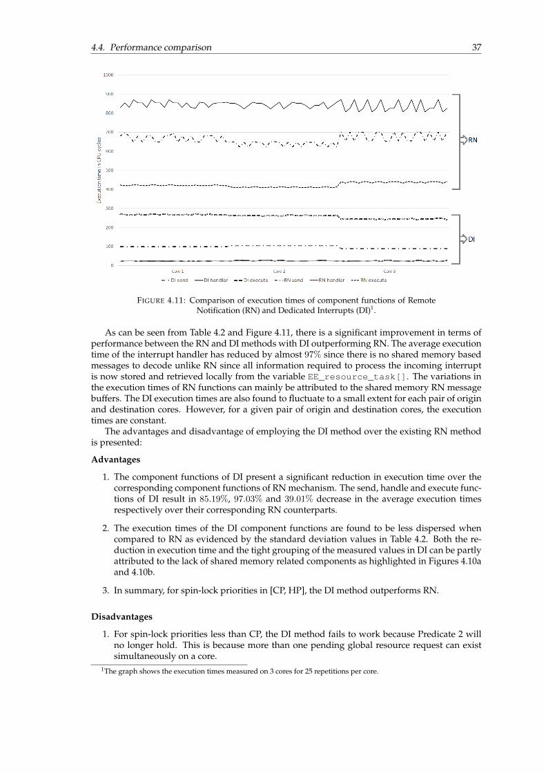
4.4. Performance comparison 37
FIGURE 4.11: Comparison of execution times of component functions of RemoteNotification (RN) and Dedicated Interrupts (DI)1.
As can be seen from Table 4.2 and Figure 4.11, there is a significant improvement in terms ofperformance between the RN and DI methods with DI outperforming RN. The average executiontime of the interrupt handler has reduced by almost 97% since there is no shared memory basedmessages to decode unlike RN since all information required to process the incoming interruptis now stored and retrieved locally from the variable EE_resource_task[]. The variations inthe execution times of RN functions can mainly be attributed to the shared memory RN messagebuffers. The DI execution times are also found to fluctuate to a small extent for each pair of originand destination cores. However, for a given pair of origin and destination cores, the executiontimes are constant.
The advantages and disadvantage of employing the DI method over the existing RN methodis presented:
Advantages
1. The component functions of DI present a significant reduction in execution time over thecorresponding component functions of RN mechanism. The send, handle and execute func-tions of DI result in 85.19%, 97.03% and 39.01% decrease in the average execution timesrespectively over their corresponding RN counterparts.
2. The execution times of the DI component functions are found to be less dispersed whencompared to RN as evidenced by the standard deviation values in Table 4.2. Both the re-duction in execution time and the tight grouping of the measured values in DI can be partlyattributed to the lack of shared memory related components as highlighted in Figures 4.10aand 4.10b.
3. In summary, for spin-lock priorities in [CP, HP], the DI method outperforms RN.
Disadvantages
1. For spin-lock priorities less than CP, the DI method fails to work because Predicate 2 willno longer hold. This is because more than one pending global resource request can existsimultaneously on a core.
1The graph shows the execution times measured on 3 cores for 25 repetitions per core.

38 Chapter 4. Inter-core communication
4.5 Compatibility for spin-lock priorities in [LP,CP)
The initial [3][4] and new implementations of FSLM have been created as a proof of concept onthe Erika Enterprise RTOS while only considering spin-lock priorities in the range [CP, HP]. Asa result, few design choices have been made with the idea of optimizing the performance of thesoftware for only for [CP, HP] on the specific platform of choice (Altera Nios II). This sectionexplains a list of such design choices which might not be suitable when spin-lock priorities in[LP,CP) or other platforms are also considered.
1. For enabling non-preemptive execution of global critical sections, the system ceiling mustbe raised to a non-preemptive level. In the initial implementation [4], it is assumed thatthere can be at most 8 separate priorities on the core. Hence, an 8-bit value of 0x80 (10000000 in binary) is chosen as the non-preemptive system ceiling. Thus, the implementationwill likely not work for platforms with 16 or 32 bit priorities and hence, the value of non-preemptive system ceiling should be increased to 0x0800 or 0x8000 respectively.
2. In both the initial and new implementations, the interrupt handlers EE_rn_handler()and EE_di_handler() respectively are designed for spin-lock priorities in [CP, HP] underthe assumption that Predicate 2 always holds. Thus, the handler no longer keeps track ofnew incoming interrupts while executing an already received interrupt unlike the native RNhandler implementation in Erika. However, when spin-lock priorities in [LP,CP) are alsoconsidered, Predicate 2 no longer holds and the handler will likely fail to work as expected.
3. The EE_rn_execute() and EE_di_execute() functions in the initial and new imple-mentations respectively are also specifically designed for spin-lock priorities in [CP, HP].As a result, the context switch into the task requesting the global resource for the executionof its global critical section is made by the interrupt handler. This also assumes that Pred-icate 2 holds and no other interrupt will be received until the completion of execution ofthe global critical section. Since nested access of global resources are not allowed in FSLMthis design choice was made in [4]. However, when other spin-lock priorities in [LP,CP) areconsidered, this system would likely fail to work as expected.
4. Since RN message buffers are no longer used, a new local data structure EE_resource_task[]has been introduced in DI method. Although this could also be achieved by using a singleunprotected global data structure, since on different platforms, the access times for globalmemory might be significantly longer than for local memory, the choice was made to uselocal memory for storing the data structure EE_resource_task[].
4.6 Recommendations for integration with Erika Enterprise
The presented DI implementation in Erika Enterprise has been performed as a proof of concept.However, it might be desirable to extend Erika Enterprise in the future with full featured sup-port for FSLM and consequently the DI mechanism. The possible options for integrating the DImechanism with the full featured version of Erika Enterprise are investigated in this section.
In the implementation created for this project, the Erika Enterprise kernel has been signifi-cantly reduced to merely support the implementation of FSLM. As a result, since none of theoriginal RN message types supported by the native Erika Enterprise in Listing 4.1 are used forFSLM, the RN feature was completely replaced by the DI mechanism which uses the same inter-core interrupt lines originally used by RN. However, for a full featured version of Erika Enter-prise, there might be a requirement for the features of FSLM including DI to co-exist with otherdefault RN message types, potentially used for non-RAP related parts of the application. Also,when FSLM spin-lock priorities in [LP,CP) are considered in the future, the co-existence of DI andRN might be desired as DI does not support spin-lock priorities less than CP. Thus, an investiga-tion is performed to determine the possible options and presented as recommendations.
Based on the implementation of DI and the similarities between the component functions ofRN and DI methods, the following options are most likely to be considered for the integration ofthe DI mechanism into Erika Enterprise. The features of both the options are briefly explored.
• Option 1: Implement DI as a special case of RN mechanism.
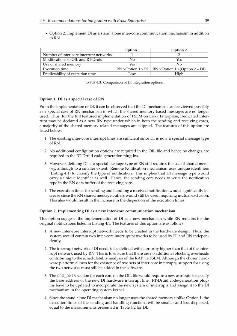
4.6. Recommendations for integration with Erika Enterprise 39
• Option 2: Implement DI as a stand alone inter-core communication mechanism in additionto RN.
Option 1 Option 2Number of inter-core interrupt networks 1 2Modifications to OIL and RT-Druid No YesUse of shared memory Yes NoExecution time RN >Option 1 >DI RN >Option 1 >(Option 2 = DI)Predictability of execution time Low High
TABLE 4.3: Comparison of DI integration options.
Option 1: DI as a special case of RN
From the implementation of DI, it can be observed that the DI mechanism can be viewed possiblyas a special case of RN mechanism in which the shared memory based messages are no longerused. Thus, for the full featured implementation of FSLM on Erika Enterprise, Dedicated Inter-rupt may be declared as a new RN type under which in both the sending and receiving cores,a majority of the shared memory related messages are skipped. The features of this option arelisted below:
1. The existing inter-core interrupt lines are sufficient since DI is now a special message typeof RN.
2. No additional configuration options are required in the OIL file and hence no changes arerequired in the RT-Druid code-generation plug-ins.
3. However, defining DI as a special message type of RN still requires the use of shared mem-ory, although to a smaller extent. Remote Notification mechanism uses unique identifiers(Listing 4.1) to classify the type of notification. This implies that DI message type wouldcarry a unique identifier as well. Hence, the sending core needs to write the notificationtype in the RN data buffer of the receiving core.
4. The execution times for sending and handling a received notification would significantly in-crease since the RN shared message buffers would still be used, requiring mutual exclusion.This also would result in the increase in the dispersion of the execution times.
Option 2: Implementing DI as a new inter-core communication mechanism
This option suggests the implementation of DI as a new mechanism while RN remains for theoriginal notifications listed in Listing 4.1. The features of this option are as follows:
1. A new inter-core interrupt network needs to be created in the hardware design. Thus, thesystem would contain two inter-core interrupt networks to be used by DI and RN indepen-dently.
2. The interrupt network of DI needs to be defined with a priority higher than that of the inter-rupt network used by RN. This is to ensure that there are no additional blocking overheadscontributing to the schedulability analysis of the RAP, i.e FSLM. Although the chosen hard-ware platform allows for the existence of two sets of inter-core interrupts, support for usingthe two networks must still be added in the software.
3. The CPU_DATA section for each core on the OIL file would require a new attribute to specifythe base address of the new DI hardware interrupt line. RT-Druid code-generation plug-ins have to be updated to incorporate the new system of interrupts and assign it to the DImechanism in the operating system kernel.
4. Since the stand alone DI mechanism no longer uses the shared memory unlike Option 1, theexecution times of the sending and handling functions will be smaller and less dispersed,equal to the measurements presented in Table 4.2 for DI.

40 Chapter 4. Inter-core communication
Table 4.3 summarizes the comparison between the two options for integration of DI in ErikaEnterprise. The execution times of RN and DI presented in Table 4.2 are used to provide anestimate for the execution times of the two explored options. It can be observed that althoughOption 2 requires an additional set of inter-core interrupt lines and minor modification to thecode-generation plug-ins, the performance is expected to be significantly better than Option 1.

41
Chapter 5
Dual shared stacks
In this chapter, the runtime stack memory utilization for the selected range of spin-lock priorities[CP, HP] in FSLM is explored. A method of using two stacks per core for restricted spin-lockpriorities is proposed and a proof of concept is created in the Erika Enterprise implementation ofFSLM.
5.1 Runtime stack space
Stack space of a task in a system with support for multiple tasks can be defined as the reservedmemory space for the storage of the task context, i.e, the contents of the CPU registers [16]. Inconventional operating systems, to enable seamless support for multiple tasks with interleavedtask executions and preemptions, each task in the system typically has its own private predefinedstack space. A potential drawback of this method is the fact that with an increase in the numberof tasks, significant amount of memory is required for the stacks of all the tasks. This could beproblematic in the case of real-time embedded systems since such systems are usually resourceconstrained and memory resources might be at a premium.
Sharing of a single runtime stack by multiple tasks has been proposed previously in workssuch as SRP [15] and MSRP [5]. A stack incorporates two functions namely push and pop. A pushoperation adds an element to the top of the stack. An element in this case refers to the contextof a task. A pop operation removes the most recently added element from the top of the stack.Thus, a stack is Last In First Out (LIFO) ordered. An element that is popped from a stack mustbe immediately used by the active task to prevent the loss of the popped element. Since the popoperation removes the most recently added element, it is only possible to resume a task that is atthe top of the stack. As a consequence of the above properties of a stack, two or more tasks withinterleaving executions cannot inhabit the same shared stack.
(A) FSLM-HP (B) FSLM-CP
FIGURE 5.1: FSLM single stack evolutions under HP and CP approaches.
42 Chapter 5. Dual shared stacks
Figure 5.1a shows a sample evolution of tasks on a core using a shared stack space under theFSLM-HP approach. The concept of interleaved executions among tasks sharing a common stackspace leading to stack inter-penetration is illustrated in Figure 5.1b. At time t = 5, the spinningtask τ0 is preempted by τ1. The top of the stack now contains the context and CPU registers of taskτ1. At time t = 8, τ1 is preempted by τ2 thereby placing the context of τ2 at the top of the stack. Attime t = 11, the resource access is granted to τ0 which must immediately begin the execution ofits global critical section. However, the context of the task τ0 is not at the top of the stack as shownin Figure 5.1b. This scenario results in an interleaved execution of tasks and hence showing thatfor a spin-lock approach less than HP, a single shared stack space per core is insufficient.
5.2 Stack requirement - FSLM
This section presents an argument regarding the maximum number of stacks required per corefor FSLM. Ignoring the implementation overheads, the HP spin-lock approach of FSLM is similarto MSRP. It has been shown in [5] that using spin-lock priority equal to πmax
Pk, i.e HP spin-lock
priority allows using a single stack for all tasks in the core. The authors of [7] present a theoremusing a series of lemmas to show that it is sufficient to use two stacks on each core for all spin-lockpriorities in the range [CP, HP).
A brief recap of the theorem and the set of lemmas that support the proof of the hypothesispresented in [7] is as follows:
Lemma 1. The local resource sharing protocol SRP ensures that once a job is started, it cannot be blockeddue to a local resource until completion; it can only be preempted by higher priority jobs [15].
Lemma 2. For any task τi ∈ TPkwhere πi ≤ πspin
Pka job of lower priority task which is preempted by a job
of τi cannot execute until the job of τi is finished.
Lemma 3. For any two tasks τi ∧ τj ∈ TPkwhere πspin
Pk< πi, πj < πmax
Pka job of τj which is preempted
by a job of τi cannot execute until the job of τi is finished.
The above lemmas are used in [7] to establish the following theorem:
Theorem 1. For a spin-lock priority πspinPk
in the range [πGPk, πmaxPk
), FSLM allows the set of tasks on corePk to require only two stacks, i.e. tasks with a priority at most πspin
Pkshare one stack and the other tasks
share another stack.
A complete textual proof of the above theorem can be found in Section 4 of [7]. The theoremproves that while following the suggested stack allocation, there will be no interleaved executionof tasks sharing the same stack. This serves as a motivation for the implementation of dual sharedstack for the implementation of FSLM in Erika Enterprise. The initial implementation of FSLMon Erika presented in [4] and [3] uses an individual stack for every task in a core.
5.3 Stack configuration options in Erika Enterprise
Erika Enterprise allows for the specification of RTOS objects before compilation. OSEK Imple-mentation Language (OIL) [42] Language, a text based description language, is used for the spec-ification of the objects that exist in the application. The OIL file then serves as the input forRT-Druid [37], a dedicated tool-suite providing a system modeler, code-generator plug-ins for theopen-source Eclipse framework [38] and schedulability analysis plug-ins. The OIL file is parsedby RT-Druid code-generator resulting in the generation and compilation of the application. Thissection presents a brief overview of the available options for configuring the runtime stack ofthe tasks in the multi-core extension of the “BCC2” conformance class of the OO (OSEK OS) ker-nel [39] of Erika Enterprise.
Static RTOS objects such as tasks and resources can be predefined at application compile timein the OIL file. To specify the stack related configuration parameters for the application, thefollowing objects in the OIL file are used:
i) CPU object

5.3. Stack configuration options in Erika Enterprise 43
ii) OS object
iii) Task object
The objects are used as containers for specifying the relevant attributes which can be numbers,strings or enumerations based on the nature of the attribute. The attributes can also be containedwithin so called “sections” within the objects. An exhaustive list of all the attributes and corre-sponding configuration parameters for all objects in the OIL file can be found in [37] and [42].
5.3.1 CPU object
The CPU object in an OIL file is used as a container for all the other objects and it does not haveany attributes. The OS object and Task objects are contained within the CPU object. It is to benoted that there is only one CPU object in an OIL file.
5.3.2 OS object
The OS object contains the compilation parameters and the global configuration for the ErikaEnterprise kernel. A non-exhaustive list of attributes contained within the OS object are listedbelow:
• Compilation attributes
• OSEK attributes
• Multi-core attributes
• Nios-II target attributes (specific to Altera Nios-II [27] target)
• CPU_DATA sections
• Kernel conformance class
Listing 5.1 shows a sample snippet from an OIL file for a Nios II based two-core system. Thelisting shows the CPU object and the OS object along with a few attributes specified under the OSobject.
1 CPU test_application {2
3 /* --- Begin OS object --- */4
5 OS EE {6 /* --- Begin Compilation attributes --- */7
8 CFLAGS = "-DALT_DEBUG -O0 -g";9 CFLAGS = "-Wall";
10 LDFLAGS = "-Wl,-Map -Wl,project.map";11 ASFLAGS = "-g";12 LDDEPS = "\\";13 LIBS = "-lm";14
15 /* --- End Compilation attributes --- */16
17 /* --- Begin Nios II target attributes --- */18
19 NIOS2_SYS_CONFIG = "Debug";20 NIOS2_APP_CONFIG = "Debug";21 NIOS2_DO_MAKE_OBJDUMP = TRUE;22 MASTER_CPU = "cpu0";23 IPIC_GLOBAL_NAME = "IPIC_OUTPUT";24 NIOS2_PTF_FILE = "C:/altera/Projects/four_core_mar23/four_core_SOPC.ptf";25 NIOS2_MUTEX_BASE = "MUTEX_0_BASE";26
27 /* --- End Nios II target attributes --- */28
29 /* --- Begin CPU_DATA section - CPU 0 --- */30
31 CPU_DATA = NIOSII {32 ID = "cpu0";33 MULTI_STACK = TRUE;34 APP_SRC = "cpu0_main.c";35 APP_SRC = "shareddata.c";36 STACK_TOP = "__alt_stack_pointer";37 SYS_SIZE = 0x1000;

44 Chapter 5. Dual shared stacks
38 SYSTEM_LIBRARY_NAME = "erika_syslib_c0";39 SYSTEM_LIBRARY_PATH = "C:/altera/Projects/four_core_mar23/software/erika_muthu_5/erika_syslib_c0";40 IPIC_LOCAL_NAME = "IPIC_INPUT_0";41 };42
43 /* --- End CPU_DATA section - CPU 0 --- */44
45 /* --- Begin CPU_DATA section - CPU 1 --- */46
47 CPU_DATA = NIOSII {48 ID = "cpu1";49 MULTI_STACK = TRUE;50 APP_SRC = "cpu1_main.c";51 APP_SRC = "shareddata.c";52 STACK_TOP = "__alt_stack_pointer";53 SYS_SIZE = 0x1000;54 SYSTEM_LIBRARY_NAME = "erika_syslib_c1";55 SYSTEM_LIBRARY_PATH = "C:/altera/Projects/four_core_mar23/software/erika_muthu_5/erika_syslib_c1";56 IPIC_LOCAL_NAME = "IPIC_INPUT_1";57 };58
59 /* --- End CPU_DATA section - CPU 1 --- */60
61 /* --- Begin Multi-core attributes --- */62
63 STARTUPSYNC = TRUE;64 USEREMOTETASK = ALWAYS;65
66 /* --- End Multi-core attributes --- */67
68 /* --- Begin OSEK attributes --- */69
70 STATUS = EXTENDED;71 STARTUPHOOK = FALSE;72 ERRORHOOK = FALSE;73 SHUTDOWNHOOK = FALSE;74 PRETASKHOOK = FALSE;75 POSTTASKHOOK = FALSE;76 USEGETSERVICEID = FALSE;77 USEPARAMETERACCESS = FALSE;78 USERESSCHEDULER = FALSE;79 /* --- End OSEK attributes --- */80
81 //Kernel Conformance class82 KERNEL_TYPE = BCC2;83 };84
85 /* --- End OS object --- */86
87 /* Space for TASK objects*/88 };
LISTING 5.1: Example 2-core OIL file snippet - CPU object and OS object.
With respect to the stack configuration, within the OS object, the CPU_DATA section is of interestand is explained further.
5.3.3 CPU_DATA section
In a typical multi-core system, the OS object contains a CPU_DATA section for every individualcore in the system.
• The MULTI_STACK attribute in that section is used to define whether or not the system sup-ports multiple stacks for the application tasks in that core. The attribute can be set to TRUEor FALSE. In the example Listing 5.1, for CPUs 0 and 1, the definition of the MULTI_STACKattribute can be found in lines 33 and 49 respectively.
• For Nios II based systems [27], the architecture allows for a default stack on each core namedDUMMY_TASK. Erika Enterprise schedules the main() function on each core as a back-ground task, named as “dummy” task on this DUMMY_STACK. As mentioned, the DUMMY_STACKis feature based on the architecture and hence is not explicitly defined as an attribute in theCPU_DATA section.
• The SYS_SIZE attribute is used to specify the total stack memory allocated to all the tasksin that core (total stack memory irrespective of shared or private stacks).
5.4. Dual shared stack for FSLM in Erika 45
5.3.4 TASK object
The TASK objects are specified within the CPU object to configure the properties of individualtasks in the application. Similar to OS object, it is desirable to primarily investigate the “stack”related attributes of the TASK object in this section while an exhaustive list of all attributes can befound in [37].
• TASK keyword marks the definition of a TASK object.
• CPU_ID attribute is used to specify the CPU (core) to which the task is mapped.
• APP_SRC attribute is used to specify the path the application source file containing the im-plementation of the task.
• PRIORITY specifies the priority of the task. Similar to the definition of task priority in thesystem model (Chapter 3.1), the priority of a task τi is greater than that of τj if i > j.
• RESOURCE is used to specify the resources (local and global) utilized by the task. A TASKobject can contain multiple RESOURCE attributes.
• STACK attribute in the task object is used to specify if the task uses a dedicated private stackor a shared stack. The attribute can be set to PRIVATE or SHARED. Setting a private stackalso allows for the specification of an individual stack size using the SYS_SIZE attribute.When tasks in a core are configured with SHARED stack, RT-Druid code-generator assignsthe tasks to the default DUMMY_STACK on which the main() function is scheduled as a“dummy” task as explained in Section 5.3.3.
1 TASK task2 {2 CPU_ID = "cpu0";3 APP_SRC = "task2.c";4 PRIORITY = 3;5 ACTIVATION = 1;6 SCHEDULE = FULL;7 AUTOSTART = FALSE;8 STACK = PRIVATE{ SYS_SIZE = 0x100; };9 };
10
11 TASK task3 {12 CPU_ID = "cpu1";13 APP_SRC = "task3.c";14 PRIORITY = 1;15 ACTIVATION = 1;16 SCHEDULE = FULL;17 AUTOSTART = FALSE;18 STACK = SHARED;19 RESOURCE = mutex1;20 };
LISTING 5.2: Example OIL file snippet - Task objects with shared and privatestacks.
Listing 5.2 shows an example declaration of two tasks “task2” and “task3” allocated to cores“cpu0” and “cpu1” respectively. It can be seen in line 8 that “task2” is configured with a PRIVATEstack of size 256 bytes. Whereas, “task3”, as seen in line 18 is configured with a SHARED stack.
5.4 Dual shared stack for FSLM in Erika
The options available for configuring the application task stacks in Erika Enterprise were brieflydescribed in the previous section (Section 5.3). This section presents a method for utilizing theavailable stack configuration options to create two stacks per core for the implementation of FSLMin Erika Enterprise. In order to leverage the existing configuration options, the section also brieflydescribes the code-generation flow of RT-Druid with a focus on the stack configuration options.
5.4.1 RT-Druid auto code-generation for stack configuration
The RT-Druid [37] code-generation plug-ins use the OIL file as the input to automatically gen-erate the operating system configuration files specific to the application defined in the OIL file.

46 Chapter 5. Dual shared stacks
FIGURE 5.2: Partial overview of RT-Druid automatic code-generation architecture
Figure 5.2 shows a partial overview of the automatic code-generation architecture of RT-Druid.It can be seen from the figure that the RT-Druid tool requires the conf.OIL file to generate corespecific configuration files. RT-Druid generates 2 files namely eecfg.h and eecfg.c for eachcore in the system. A file named common.c is generated only for the MASTER_CPU in the system.According to [43], the role of the Master CPU is to initialize the shared data.
• common.c contains the definitions for macros related to the synchronization during startupand spin-locks in the HAL layer. This file is generated only for the Master CPU.
• eecfg.h contains the common defines for each CPU including the defines related to thetask IDs, mutex definitions and other options pertaining to the attributes specified in theOIL file.
• eecfg.c contains the definitions and initialization of data structures related to the kernel,mutexes, alarms, counters and interrupts. This file also contains the stack definition forapplication.
Data structures in the stack definition
The following data structures are used in the stack definition of every core in the file eecfg.c.
• __alt_stack_pointer - The symbol used inside Altera Nios II system libraries as theinitial stack pointer.
• EE_hal_thread_tos[] - An array containing the indices of the top of stack (tos) corre-sponding to each task in the core and the main() function. Index 0 always corresponds tothe main() function that is scheduled as a background task.
• EE_nios2_system_tos[] - An array with the actual addresses of the tos pointers. Index0 always refers to the tos of the DUMMY_STACK.
• EE_hal_active_tos - Denotes the currently active stack. Initialized to 0 always duringstartup.
The data structures are explained further by considering the following example scenario.

5.4. Dual shared stack for FSLM in Erika 47
Example 3. Consider a core with four tasks τ0, τ1, τ2 and τ3. The task names in plain-text are “task0”,“task1”. “task2” and “task3” respectively. Tasks τ0 and τ1 are configured with the TASK attribute set toSHARED while τ2 and τ3 are configured with PRIVATE stacks.
1 extern int __alt_stack_pointer;2 #define __RTD_SYS_STACK_ADDRESS \3 (int)(&__alt_stack_pointer)4
5 EE_UREG EE_hal_thread_tos[EE_MAX_TASK+1] = {6 0, /* dummy*/7 0, /* task0*/8 0, /* task1*/9 1, /* task2*/
10 2 /* task3*/11 };12
13 struct EE_TOS EE_nios2_system_tos[3] = {14 {(EE_ADDR)(__RTD_SYS_STACK_ADDRESS )},15 {(EE_ADDR)(__RTD_SYS_STACK_ADDRESS- 3584 -36 )},16 {(EE_ADDR)(__RTD_SYS_STACK_ADDRESS- 3840 -36 )}17 };18
19 EE_UREG EE_hal_active_tos = 0; /* dummy */
LISTING 5.3: Example auto-generated stack configuration - snippet from eecfg.c.
Listing 5.3 shows the auto-generated stack definition by RT-Druid tool for the system de-scribed in Example 3. It can be seen from the listing that the array EE_nios2_system_tos[]consists of 3 addresses, denoting the starting address for each of the three stacks on the core.The total number of tasks in a core is one greater than the number of user-defined tasks to ac-commodate for the main() function as a background task. Hence, in the presented example,the number of tasks in the core is 5. The array EE_hal_thread_tos[] in the listing has 5 el-ements, with each index denoting a task. The main() function is always denoted by index 0,followed by the user-defined tasks as indicated by the comments in the listing. The value ateach index in the array EE_hal_thread_tos[] denotes the corresponding stack (defined inEE_nios2_system_tos[]) to which the task belongs. Hence, in this example, it is can be seenthat the 5 tasks (including the main() function) are allocated to 3 stacks, where tasks τ0 and τ1share the default shared stack along with the main() function while tasks τ2 and τ3 are allocatedprivate stacks.
5.4.2 Configuration for dual shared stack
It can be observed from the available stack configuration options in Erika Enterprise that all taskswith TASK attribute set to SHARED are allocated to the default stack (DUMMY_STACK). To createanother shared task, one of the two following options exist:
1. Modify the RT-Druid tool by adding additional keywords for the TASK attribute to auto-assign tasks to two shared stacks.
2. Leverage the existing tooling and modify the auto-generated eecfg.c files to create twoshared stacks on each core.
Since the FSLM implementation on Erika Enterprise is currently intended as a proof of con-cept, it is desirable to select an approach which retains the native tooling and code-generationplug-ins. Considering that any modifications to the RT-Druid tool chain would require extensiveassistance from Evidence S.r.l., the latter option of modifying the auto-generated code with theexisting RT-Druid code-generation plug-ins was chosen.
Implementing dual shared stack
In order to leverage the existing single shared stack per core support in Erika Enterprise in theprocess of creating dual shared stack, the following method is employed:
• Since the tasks with priorities at most πspinPk
for spin-lock priorities in [CP, HP) can share onestack, their STACK attributes are set to SHARED. This ensures that these tasks are automati-cally assigned to the default common shared stack (DUMMY_STACK).
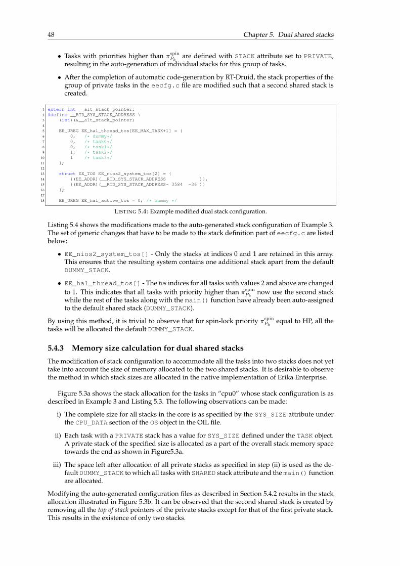
48 Chapter 5. Dual shared stacks
• Tasks with priorities higher than πspinPk
are defined with STACK attribute set to PRIVATE,resulting in the auto-generation of individual stacks for this group of tasks.
• After the completion of automatic code-generation by RT-Druid, the stack properties of thegroup of private tasks in the eecfg.c file are modified such that a second shared stack iscreated.
1 extern int __alt_stack_pointer;2 #define __RTD_SYS_STACK_ADDRESS \3 (int)(&__alt_stack_pointer)4
5 EE_UREG EE_hal_thread_tos[EE_MAX_TASK+1] = {6 0, /* dummy*/7 0, /* task0*/8 0, /* task1*/9 1, /* task2*/
10 1 /* task3*/11 };12
13 struct EE_TOS EE_nios2_system_tos[2] = {14 {(EE_ADDR)(__RTD_SYS_STACK_ADDRESS )},15 {(EE_ADDR)(__RTD_SYS_STACK_ADDRESS- 3584 -36 )}16 };17
18 EE_UREG EE_hal_active_tos = 0; /* dummy */
LISTING 5.4: Example modified dual stack configuration.
Listing 5.4 shows the modifications made to the auto-generated stack configuration of Example 3.The set of generic changes that have to be made to the stack definition part of eecfg.c are listedbelow:
• EE_nios2_system_tos[] - Only the stacks at indices 0 and 1 are retained in this array.This ensures that the resulting system contains one additional stack apart from the defaultDUMMY_STACK.
• EE_hal_thread_tos[] - The tos indices for all tasks with values 2 and above are changedto 1. This indicates that all tasks with priority higher than πspin
Pknow use the second stack
while the rest of the tasks along with the main() function have already been auto-assignedto the default shared stack (DUMMY_STACK).
By using this method, it is trivial to observe that for spin-lock priority πspinPk
equal to HP, all thetasks will be allocated the default DUMMY_STACK.
5.4.3 Memory size calculation for dual shared stacks
The modification of stack configuration to accommodate all the tasks into two stacks does not yettake into account the size of memory allocated to the two shared stacks. It is desirable to observethe method in which stack sizes are allocated in the native implementation of Erika Enterprise.
Figure 5.3a shows the stack allocation for the tasks in “cpu0” whose stack configuration is asdescribed in Example 3 and Listing 5.3. The following observations can be made:
i) The complete size for all stacks in the core is as specified by the SYS_SIZE attribute underthe CPU_DATA section of the OS object in the OIL file.
ii) Each task with a PRIVATE stack has a value for SYS_SIZE defined under the TASK object.A private stack of the specified size is allocated as a part of the overall stack memory spacetowards the end as shown in Figure5.3a.
iii) The space left after allocation of all private stacks as specified in step (ii) is used as the de-fault DUMMY_STACK to which all tasks with SHARED stack attribute and the main() functionare allocated.
Modifying the auto-generated configuration files as described in Section 5.4.2 results in the stackallocation illustrated in Figure 5.3b. It can be observed that the second shared stack is created byremoving all the top of stack pointers of the private stacks except for that of the first private stack.This results in the existence of only two stacks.

5.4. Dual shared stack for FSLM in Erika 49
(A) Auto-generated stack (B) Stack after modification
FIGURE 5.3: Example Dual shared stack overview.
IRQ stack space
Similar to the stack space requirement for tasks in a system, the Interrupt Requests (IRQs) alsorequire runtime memory. In Erika Enterprise, setting the MULTI_STACK attribute to TRUE alsoallows for the setting of another attribute named IRQ_STACK. Setting the value of the attributeIRQ_STACK to TRUE specifies that the IRQs are executed using their own dedicated stack space.The size of the dedicated IRQ stack can then be specified using the SYS_SIZE attribute.
1 MULTI_STACK = TRUE {2 IRQ_STACK = TRUE {3 SYS_SIZE = 0x200;4 };5 };
LISTING 5.5: OIL file snippet showing IRQ_STACK configuration.
Listing 5.5 shows an example declaration of a dedicated IRQ stack in the OIL file. How-ever, unless specified, the default value of IRQ_STACK in Erika Enterprise is automatically setto FALSE. This signifies that the IRQs also utilize a part of the stack space allocated to the tasks.In a system with multiple tasks with each task having its own private stack and IRQ_STACK setto FALSE, every private stack consists of an additional IRQ stack space. The implementation ofFSLM on Erika is configured without dedicated IRQ stacks, i.e., IRQ_STACK is set to FALSE.
Calculating the stack memory requirement
A method for calculating the appropriate stack sizes for the two stacks in a dual shared stack ispresented. This calculation is presented to serve as a guide for setting the values of the SYS_SIZEattributes in the CPU_DATA section of the core as well as in the TASK objects such that the result-ing shared stack sizes after modifying the eecfg.c file will be appropriate. The following set ofterms are defined to aid in the memory requirement calculation:

50 Chapter 5. Dual shared stacks
λTPkOverall memory size for all stacks in a core Pk.
λmPkStack space requirement for the main() function of core Pk.
λIRQ Stack space requirement associated with IRQ.
λi Stack space requirement for task τi (without IRQ stack space)
λS0
PkSize of the first shared stack S0 including IRQ space (tasks with πi ≤ πspin
Pk).
λS1
PkSize of the second shared stack S1 including IRQ space (tasks with πi > πspin
Pk).
nS0
PkNumber of tasks in stack S0 of core Pk.
nS1
PkNumber of tasks in stack S1 of core Pk.
The value of the memory size required for the first shared stack S0 also includes the stack spacerequired for handling IRQs and the default background task (main() function). It is defined as:
λS0
Pk= λmPk
+ λIRQ +∑
∀i:τi∈TPk
∧πi≤πspinPk
λi. (5.1)
Similarly, the value of the memory size required for the second shared stack S1 is defined as:
λS1
Pk= λIRQ +
∑∀i:τi∈TPk
∧πi>πspinPk
λi. (5.2)
The overall memory size required on a core Pk to accommodate all the tasks in the core in-cluding the default background task (main() function) and IRQs is calculated as follows:
λTPk= λS0
Pk+ λS1
Pk. (5.3)
OIL file configuration values
By using the above equations, it is possible to determine the value of SYS_SIZE attribute underboth the CPU_DATA section and the TASK object in the OIL file for every core.
The SYS_SIZE attribute under the CPU_DATA section of the OS object which specifies the totalmemory requirement for all stacks on the core Pk is given by:
∀Pk∈P
SYS_SIZEPk= λTPk
, (5.4)
where SYS_SIZEPkdenotes the SYS_SIZE attribute under the CPU_DATA section of core Pk in
the OIL file.The cumulative size of all the private stacks of the tasks with priority greater than the spin-
lock priority on the core must be equal to λS1
Pk. If SYS_SIZEi denotes the SYS_SIZE attribute
under the TASK object in the OIL file, for every task with priority greater than πspinPk
this can berepresented as: ∑
τi∈TPk
∧πi>πspinPk
SYS_SIZEi = λS1
Pk. (5.5)
By using (5.5), it is possible to calculate SYS_SIZEi for each individual task in the core withpriority greater than πspin
Pk. One possible definition for SYS_SIZEi can be:
∀τi∈TPk
∧πi>πspinPk
SYS_SIZEi =
⌈λS1
Pk
nS1
Pk
⌉. (5.6)

5.5. Memory savings associated with dual shared stack 51
Alternatively, it is also possible to define SYS_SIZEi in any suitable way as long as the sum ofall the private stacks of the tasks with priority greater than the spin-lock priority on the core isequal to λS1
Pkas illustrated in (5.5). This ensures that when the second shared stack is created by
merging all the privates stacks, the newly created shared stack will have sufficient memory toaccommodate all the tasks and also the space required for an IRQ stack.
5.5 Memory savings associated with dual shared stack
This section investigates the savings in terms of memory space achieved while utilizing the dualshared stacks per core instead of the conventional method of individual stack per task.
In uni-processor context, SRP allows for the sharing of runtime stack. The use of so called“preemption levels” associated with every task apart from the priority of the task allows for largerstack saving with an increase in the number of tasks with the same preemption level [16]. Multipletasks can share the same preemption level and two or more jobs sharing the same preemptionlevel can never occupy a stack space at the same time. In multiprocessor context, fixed priorityscheduling with preemption thresholds (FPTS) [44] is an example of such a method. Thus, inan example application consisting of 100 jobs each requiring 10Kbytes of stack distributed over10 preemption levels [16], the overall stack space requirement would be 100Kbytes in case of asingle shared stack. When compared to the overall stack requirement of 1000Kbytes if the tasksare allocated private stacks, the shared stack offers 90% saving in the memory requirement forthis example.
In FSLM, the preemption levels are assumed to be equal to the priorities of the respectivetasks. Since the priorities of all the tasks on a core must be unique, in the worst-case scenario,all the tasks could potentially occupy the same stack space simultaneously. Hence, for FSLM, theworst-case memory requirement for the stacks is equal to the sum of all the individual task stackrequirements in the core. However, the IRQ stack requirement would significantly reduce in caseof the dual shared stack implementation when compared to the private stacks method.
Let λTWC
Pkrepresent the worst-case total stack memory requirement for core Pk while using
private stacks for all tasks in the core. The value can be calculated as follows:
λTWC
Pk=
∑∀i:τi∈TPk
(λi + λIRQ
). (5.7)
Now, by using the dual shared stacks, let λTWC
Pkrepresent the worst-case total stack memory re-
quirement. Unlike the previous case, λIRQ needs to be accommodated only twice, i.e, once in eachshared stack. The value can be calculated as follows:
λTWC
Pk=(2× λIRQ
)+
∑∀i:τi∈TPk
λi. (5.8)
The total savings in memory (∆λPk) can be calculated as the difference between the above two
terms:∆λPk
= λTWC
Pk− λTWC
Pk= max{0, (|TPk
| − 2)} × λIRQ, (5.9)
where |TPk| denotes the cardinality of the set TPk
, representing the number of tasks in the pro-cessor Pk. Hence, it can be observed that the reduction in memory requirement while using dualshared stack when compared to private stacks becomes more significant with an increase in thenumber of tasks in the core. The findings from this chapter were presented as a Work-in-Progresssession paper [11].


53
Chapter 6
FSLM tool
In this chapter, a brief description of a utility tool named “Flex-Tool” created for automaticallymaking the required configuration changes to FSLM implementation of Erika is presented.
6.1 Introduction
The native implementation of Erika Enterprise with MSRP uses the RT-Druid code-generatorplug-ins to configure the operating system kernel based on the user inputs from the OIL file.However, for the implementation of FSLM on Erika, features such as changing the spin-lock pri-ority of each core and modifying the stack information to accommodate dual shared stacks oneach core also need to be configured based on the application. The changes for implementingFSLM have been made outside the context of RT-Druid code-generation plug-ins since this im-plementation is intended as a proof of concept. Therefore, in order to automate certain aspects ofthe RTOS kernel configuration, a new utility tool is developed. In this chapter, a brief descriptionof the features of the tool is presented.
6.1.1 Spin-lock parameters in FSLM implementation
A set of parameters were newly defined as “extern” variables in the Erika kernel file to facilitatethe implementation of FSLM. A subset of such variables that are required to be configured oneach core during compilation are listed below:
• EE_th_spin_prio[] - Array containing the value of the spin-lock priority for each task inthe core. Hence the number of entries in this array is equal to the number of tasks mappedto the core. Since in FSLM, the same spin-lock priority is used for all the tasks in the core,all entries of this array will contain the same value.
• GlobalTaskID[] - Array containing a unique task ID for every task on the core. Numberof entries in this array is equal to the number of tasks in the core. For all the cores in thesystem, the values contained in the array are unique. This global task ID is used to managethe FIFO ordering for global resource requests while using the variable ResourceQ[] asexplained in Chapter 4.1.2.
The file ee_internal.h in the Erika Enterprise kernel contains the declaration of the abovevariables. Listing 6.1 shows the snippet from ee_internal.h containing the declarations.
1
2 /*spin-lock priority for each task in the core*/3 extern const int EE_th_spin_prio[];4
5 /*unique global task ID for every task*/6 extern const int GlobalTaskID[];
LISTING 6.1: Snippet of “extern” configuration parameters from ee_internal.h.
The initialization of the listed variables are performed in the respective main files of each corein the application. Listing 6.2 shows an example snippet of initialization from one of the cores.The snippet shows a core with three tasks τ3, τ4 and τ5 with priorities 3, 4 and 5 respectivelydefined in the OIL file. The OIL file also contained the definition for two resources. However,Erika Enterprise internally converts the priorities (πi) of the tasks in a core into 2πi , starting from
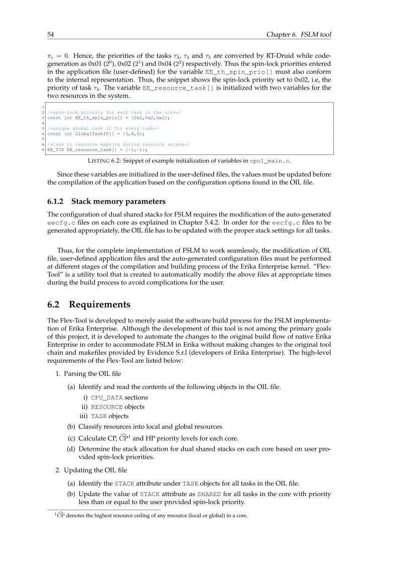
54 Chapter 6. FSLM tool
πi = 0. Hence, the priorities of the tasks τ3, τ4 and τ5 are converted by RT-Druid while code-generation as 0x01 (20), 0x02 (21) and 0x04 (22) respectively. Thus the spin-lock priorities enteredin the application file (user-defined) for the variable EE_th_spin_prio[] must also conformto the internal representation. Thus, the snippet shows the spin-lock priority set to 0x02, i.e, thepriority of task τ4. The variable EE_resource_task[] is initialized with two variables for thetwo resources in the system.
1
2 /*spin-lock priority for each task in the core*/3 const int EE_th_spin_prio[] = {0x2,0x2,0x2};4
5 /*unique global task ID for every task*/6 const int GlobalTaskID[] = {3,4,5};7
8 /*task to resource mapping during resource access*/9 EE_TID EE_resource_task[] = {-1,-1};
LISTING 6.2: Snippet of example initialization of variables in cpu1_main.c.
Since these variables are initialized in the user-defined files, the values must be updated beforethe compilation of the application based on the configuration options found in the OIL file.
6.1.2 Stack memory parameters
The configuration of dual shared stacks for FSLM requires the modification of the auto-generatedeecfg.c files on each core as explained in Chapter 5.4.2. In order for the eecfg.c files to begenerated appropriately, the OIL file has to be updated with the proper stack settings for all tasks.
Thus, for the complete implementation of FSLM to work seamlessly, the modification of OILfile, user-defined application files and the auto-generated configuration files must be performedat different stages of the compilation and building process of the Erika Enterprise kernel. “Flex-Tool” is a utility tool that is created to automatically modify the above files at appropriate timesduring the build process to avoid complications for the user.
6.2 Requirements
The Flex-Tool is developed to merely assist the software build process for the FSLM implementa-tion of Erika Enterprise. Although the development of this tool is not among the primary goalsof this project, it is developed to automate the changes to the original build flow of native ErikaEnterprise in order to accommodate FSLM in Erika without making changes to the original toolchain and makefiles provided by Evidence S.r.l (developers of Erika Enterprise). The high-levelrequirements of the Flex-Tool are listed below:
1. Parsing the OIL file
(a) Identify and read the contents of the following objects in the OIL file.
i) CPU_DATA sectionsii) RESOURCE objects
iii) TASK objects
(b) Classify resources into local and global resources
(c) Calculate CP, CP1 and HP priority levels for each core.
(d) Determine the stack allocation for dual shared stacks on each core based on user pro-vided spin-lock priorities.
2. Updating the OIL file
(a) Identify the STACK attribute under TASK objects for all tasks in the OIL file.
(b) Update the value of STACK attribute as SHARED for all tasks in the core with priorityless than or equal to the user provided spin-lock priority.
1CP denotes the highest resource ceiling of any resource (local or global) in a core.

6.3. Design and implementation 55
(c) Update the value of STACK attribute as PRIVATE for all tasks in the core with prioritygreater than the user provided spin-lock priority.
3. Updating the CPU source files
(a) Identify the following variable initializations in each CPU source file in the application:i) EE_th_spin_prio[]
ii) GlobalTaskID[]
(b) Initialize the above variables to appropriate values.
4. Updating the eecfg.c files
(a) Identify the following variable initializations in the auto-generated code of eecfg.cfile for each CPU:
i) EE_hal_thread_tos[]
ii) EE_nios2_system_tos[]
(b) Modify the above variables appropriately to create dual shared stacks.
5. User interaction
(a) Display the CP, CP and HP priority levels for each core.(b) Accept user input for one spin-lock priority value per core.(c) Convert the user provided spin-lock priority values to Erika format2.(d) Prompt user to initialize RT-Druid(e) Accept acknowledgement from user indicating the completion of RT-Druid code gen-
eration.(f) Prompt user to execute elf file generation using Eclipse build tools upon completion.
CP denotes the highest resource ceiling of any resource (local or global) in a core. Althoughthis special spin-lock priority is not a focus of this thesis, it has been explored in the analysis ofFSLM [7]. Hence, for historic reasons, it is calculated and presented to the user.
6.3 Design and implementation
The context of the Flex-Tool in the overall software build process of the FSLM implementationErika Enterprise is illustrated in Figure 6.1. The figure illustrates the files that are modified by theFlex-Tool. It is to be noted that the modifications performed by Flex-Tool occur during differentstages of the software build process and Figure 6.1 only shows the high-level context of the utilitytool. The tool was built on Python 3.5.2.
6.3.1 Working
Figure 6.2 shows a sequence diagram depicting the actions performed by the various componentsin the build process. The tasks performed by the Flex-Tool during the various stages of the buildprocess are illustrated in the figure. It can be seen that the activities of the Flex-Tool can be dividedinto three phases. A brief explanation is provided regarding the operation of the Flex-Tool basedon the sequence diagram:.
Phase 1
• When the tool is initialized, parsing of the OIL file is performed to extract the informationregarding the CPUs, tasks and resources in the application.
• The task priorities and resource map is then used to compute the priorities CP, CP and HPfor each core.
• The tool then prompts the user to input the values for spin-lock priority within the calcu-lated range for each CPU in the system.
2Erika Enterprise internally uses 2i where i = 0, 1, .., 7 to denote priority of tasks

56 Chapter 6. FSLM tool
FIGURE 6.1: Context of Flex-Tool in the software build process.
Phase 2
• The user provided spin-lock priorities are validated for correctness and converted to con-form with the internal Erika Enterprise priority format.
• Based on the spin-lock priority value for each core, the allocation of tasks to dual sharedstacks is also determined.
• The converted spin-lock priorities are then updated in the CPU source files. The data struc-tures listed in Section 6.1.1 are also updated in the CPU source files.
• The STACK attribute of the TASK objects in the OIL file are modified such that the tasks withpriority up to spin-lock priority are set to SHARED and the rest of the tasks are defined withPRIVATE stack.
• The Flex-Tool then prompts the user to initiate RT-Druid code-generation.
Phase 3
• The user indicates the completion of the RT-Druid code-generation operation followingwhich the eecfg.c files for all CPUs have now been generated.

6.3. Design and implementation 57
FIGURE 6.2: Sequence diagram for Flex-Tool actions.
• The Flex-Tool now modifies the contents of the stack declaration section of each CPU in therespective eecfg.c file as described in Chapter 5.4.2.
• The Flex-Tool finally indicates the completion of the file updates and prompts the user togenerate the Binary.elf file for programming the FPGA using the Eclipse build toolsprovided by Erika.
6.3.2 Example execution scenario
An example execution of the Flex-Tool is illustrated in Figure 6.3. The screen-capture from theexecution shows the different phases of execution. In “Phase 1”, the user is presented with theoption to select spin-lock priorities for each core in the range [CP, HP].
An interesting effect of the Flex-Tool and the method of implementation of dual shared stackscan be observed in the “Phase 2” of the figure. The method described in Chapter 5.4.2 is used forthe configuration of dual shared stacks. From the example in Figure 6.3, for CPU 0 and CPU 3, itcan be seen that there are at least 2 tasks allocated to the second shared stack. Whereas, for CPU1, there is only one task allocated to the second shared stack and in CPU 2, there are none. As aresult, for CPU 1 and CPU 2, the stack configuration resulting out of the modification to OIL filein “Phase 2” is sufficient. The eecfg.c files generated by RT-Druid for CPU 1 and CPU 2 arenot modified as can be seen in “Phase 3” of the screen-capture. Only for CPU 0 and CPU 3, therespective eecfg.c files are updated with appropriate settings to incorporate dual shared stacks.
6.3.3 Documentation
For the sake of brevity of the report and due to the fact that Flex-Tool was developed as an auxil-iary tool to automate the build process during the project, implementation details of the tool havebeen moved to the Appendix.

58 Chapter 6. FSLM tool
FIGURE 6.3: Screen-shot from Flex-Tool execution.
The complete documentation for the Flex-Tool can be found in Appendix B. A user guide de-tailing the usage of the tool has also been provided. A web version of the detailed documentationcan be found at https://srimuthu.github.io/fslm-tool-doc/.

59
Chapter 7
Overheads
The focus of this chapter is to provide a generalized method for identifying the implementationoverheads related to Resource Access Protocols (RAPs) with focus on the original Erika Enter-prise implementation of MSRP, older implementation of FSLM [3] and the new implementationof FSLM developed as a part of this study. The identified overheads are then measured on thehardware platform. The overhead components are then incorporated into the existing schedu-lability analysis of MSRP and FSLM with the intention to serve as a guideline for the choice ofappropriate RAP for a specific application.
7.1 Classification of overhead scenarios
Runtime overheads related to the implementation of the RAP occur during resource request, theinstant at which resource access is granted, and during resource release.
Figures 7.1a and 7.1b illustrate example time-lines showing the seven possible overhead sce-narios in MSRP and FSLM respectively. The system illustrated in the figures consists of four tasks(τ0, τ1, τ2, τ3) mapped onto three processors (P0, P1, P2) and a shared global resource. Task τ0 isallocated to P0, τ1 and τ2 to P1, and τ3 to P2. Tasks τ0, τ1, and τ3 use a global shared resource.In core P1, the spinning priority of the core is less than the priority of the task τ2, meaning thatτ2 can preempt τ1 while it is spinning on its resource request. The encountered overheads areclassified and labeled in Figure 7.1 according to the phase at which they occur within the contextof the RAP. A description of all the scenarios is provided below:
Resource Request:There are two overheads scenarios associated with a resource request depending upon the avail-ability of the resource at the time of request.
1. RQ1 - Denotes the runtime overheads that occur if the resource request is made when theresource is available.
2. RQ2 - Denotes the runtime overheads that occur if the resource request is made when theresource is not available, i.e. when the resource is held by a different task.
Resource Access:The following scenariosAC1,AC2 andAC3 can occur only when preceded byRQ2. If the resourcerequest was made when the resource is available (RQ1), there are no measurable implementationoverheads during resource access since the task is free to claim the resource immediately.
3. AC1 - Resource access is granted when the requesting task is at the top of the stack, i.e. ithas not been preempted. The task requesting the resource under this scenario is activelyspinning.
4. AC2 - Resource access is granted when the task requesting the resource is not at the top ofthe stack, i.e. it has been preempted while spinning by a higher priority task. Context switchhas to occur in this scenario for the requesting task to execute the global critical section (gcs).
1The numbers in the time-line are for reference purposes only. The relative sizes of overheads are not to scale.2Time-stamp 15 - illustrates the worst-case blocking context switch scenario AC3

60 Chapter 7. Overheads
(A) MSRP.
(B) FSLM.
FIGURE 7.1: Overhead1 scenarios in the implementation of MSRP and FSLM2 w.r.tresource access.
5. AC3 - Resource access can be granted at an infinitesimally small time ε after preemptionoccurs during spinning. The occurrence of a preemption begins with a context switch out ofthe spinning task into the higher priority preempting task. The context switch occurs non-preemptively and cannot be interrupted either. Hence, if the resource becomes available aninstant ε after preemption, the interrupt handler and subsequently the resource access willbe blocked until the context switch completes. Time-stamp 15 in Figure 7.1b on P1 illustratesAC3. The resource is granted to τ1 an instant ε after the preemption by τ2.
Resource Release:Resource release scenarios can also be classified into two categories based on pending requestsfor the resource being released.
6. RL1 - Resource is released when there are no pending requests for the same resource.
7. RL2 - Resource is released when there are one or subsequent pending requests for the re-source being released by tasks in other cores. Hence, the releasing core has to notify the

7.2. Identification of overhead components 61
target core while releasing the resource.
7.2 Identification of overhead components
The individual overhead components that contribute to the seven scenarios mentioned in Sec-tion 7.1 are identified in this section pertaining to the new implementation of FSLM developedfor this study. The analysis of the implementation to identify the contributing overhead compo-nents resulted in the identification of seven such individual components.
7.2.1 Resource request overheads
The overhead components that contribute to scenarios RQ1 and RQ2 are identified and definedbelow:
Def. 3. OHRQ,Gadm - Overhead associated with raising the system ceiling to non-preemptive priority and
updating the administrative data structures (book keeping) upon a global resource request.
Def. 4. OHRQ,Gspn - Overhead associated with updating the system ceiling to the spin-lock priority of the
core when the resource is unavailable.
FIGURE 7.2: Resource request overheads in FSLM (new implementation).
Figure 7.2 illustrates the overheads OHRQ,Gadm and OHRQ,G
spn with respect to the new implemen-tation of FSLM. It can be observed that OHRQ,G
spn is contained in the conditional branches therebyincluding or excluding the overhead component based on the veracity of the condition. Thewhile loop in Figure 7.2 denotes the actual spinning time where the core waits for the resourceto become available, indicated by the spin-lock variable.
7.2.2 Resource access overheads
The overhead components that contribute to scenarios AC1, AC2 and AC3 are identified anddefined below:

62 Chapter 7. Overheads
Def. 5. OHDIhdl - Overhead associated with handling an incoming inter-core interrupt. This includes
identifying the resource on which the spinning task on the incoming core is blocked, raising the systemceiling to non-preemptive priority and resetting the spin-lock upon the execution of the interrupt handler.
Def. 6. OHDIcs - Context switching overhead incurred upon the receipt of an inter-core interrupt if the
spinning task was preempted by a higher priority task.
Def. 7. OHDIbcs - Blocking context switching overhead incurred if an interrupt from a remote core is received
at an infinitesimally small time ε after preemption by a higher priority task during spinning occurs, causingthe interrupt handler to be blocked until the context switch completes.
Figure 7.3 illustrates the overheads OHDIhdl and OHDI
cs with respect to the new implementationof FSLM. It can be noted that OHDI
cs is incurred only if a preemption had occurred while the taskblocked on the global resource was spinning. Figure 7.4 illustrates an example scenario underwhich the overhead component OHDI
bcs appears. Example 4 illustrates the scenario in detail:
Example 4. Consider a two processor system consisting of processors P0 and P1 as shown in Figure 7.4.Task τ0 is mapped to P0 while tasks τ1 and τ2 are mapped to P1. Tasks τ0 and τ1 require access to the sameshared global resource R0. The task τ2 has a higher priority than τ1 and the spin-lock priority of P1 is CP,i.e, the priority of task τ1. This indicates that τ2 can preempt τ1 while it spins. τ0 arrives at t = 0 andissues a resource request to R0 at t = 2. Since the resource is available, τ0 proceeds to execute its globalcritical section (gcs) after incurring only OHRQ,G
adm . τ1 tries to access the resource at t = 3.5 and since theresource has already been locked by τ0, incurs OHRQ,G
adm and OHRQ,Gspn and starts spinning at CP priority
level on P1. At t = 8, task τ2 arrives, initiating the context switch out of the spinning task τ1. However,in the meanwhile, τ0 completes the resource access and sends a DI to core P1 at an infinitesimally smalltime ε after t = 8, i.e, at t = 10. Since the context switch routine is executed with interrupts disabled, P1
is blocked from processing the incoming DI until the completion of the context switch which is denoted asOHDI
bcs. After the completion of OHDIbcs at t = 10.5, processor P1 incurs OHDI
hdl to process the incomingpending DI. Following the interrupt handler, P1 also incurs OHDI
cs to context switch back to τ1 and thenproceeds to execute its gcs. Upon the release of the resource and completion of OHRL,G
adm at t = 17, regularpreemption related context switch occurs and the task τ2 proceeds to execute.
FIGURE 7.3: Resource access overheads in FSLM (new implementation).
Under other scenarios, unless the preemption occurs at ε before the receipt of a DI, the contextswitching overhead is simply a part of the spinning time and the term OHDI
bcs does not appear. An
1The numbers in the time-line are for reference purposes only. The relative sizes of overheads are not to scale.
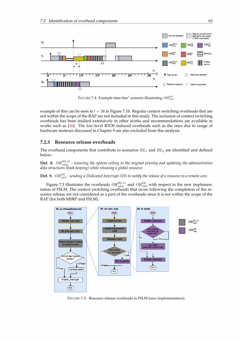
7.2. Identification of overhead components 63
FIGURE 7.4: Example time-line1 scenario illustrating OHDIbcs.
example of this can be seen at t = 26 in Figure 7.1b. Regular context switching overheads that arenot within the scope of the RAP are not included in this study. The inclusion of context switchingoverheads has been studied extensively in other works and recommendations are available inworks such as [16]. The low-level RTOS induced overheads such as the ones due to usage ofhardware mutexes discussed in Chapter 9 are also excluded from this analysis.
7.2.3 Resource release overheads
The overhead components that contribute to scenarios RL1 and RL2 are identified and definedbelow:
Def. 8. OHRL,Gadm - lowering the system ceiling to the original priority and updating the administrative
data structures (book keeping) while releasing a global resource.
Def. 9. OHDIsnd - sending a Dedicated Interrupt (DI) to notify the release of a resource to a remote core.
Figure 7.5 illustrates the overheads OHRL,Gadm and OHDI
snd with respect to the new implemen-tation of FSLM. The context switching overheads that occur following the completion of the re-source release are not considered as a part of the overheads since it is not within the scope of theRAP (for both MSRP and FSLM).
FIGURE 7.5: Resource release overheads in FSLM (new implementation).

64 Chapter 7. Overheads
7.3 Incorporating the overhead components in scenarios
Since the scenarios in which overheads can occur and also the individual overhead componentscontributing the scenarios have been identified, it is possible to represent the scenarios as a com-position of the overhead components.
RQ1 = OHRQ,Gadm RQ2 = RQ1 + OHRQ,G
spn
AC1 = OHDIhdl AC2 = AC1 + OHDI
cs
AC3 = AC2 + OHDIbcs RL1 = OHRL,G
adm
RL2 = RL1 + OHDIsnd
The worst case resource access scenario in terms of the implementation related runtime overheadsfor any task is a combination of RQ2, AC3 and RL2. This combination of scenarios consists of allthe overhead components listed in Section 7.2.
7.4 Overheads in MSRP
To facilitate a comparison between the implementations of FSLM and MSRP, it is also desirableto identify and characterize the implementation overheads in the native MSRP implementationprovided in the Erika Enterprise RTOS. This section identifies the implementation overheads inthe MSRP implementation of Erika Enterprise.
The native MSRP implementation uses a global spin-lock based method for global resourceaccess as explained in Chapter 4.1.1. FIFO ordering of resource access is provided by the use ofglobal polling-bit and "spin-status" data structure as explained. Since MSRP does not use an inter-core communication mechanism to notify resource release, there are no ISR related overheads asin the case of FSLM.
The native implementation of MSRP only incurs OHRQ,Gadm and OHRL,G
adm , which are defined byDefinitions 3 and 8 respectively. Although the definitions of the terms are identical to that ofFSLM, due to the inherent differences in the implementations of FSLM and MSRP, the values areexpected to be different. Figures 7.6 and 7.7 illustrate the overheads OHRQ,G
adm and OHRL,Gadm with
respect to the native MSRP implementation in Erika Enterprise.
FIGURE 7.6: Resource access overheads in MSRP (native implementation).
During resource request, RQ2 does not occur since spinning always happens at HP and MSRPdoes not involve setting of a local spin-lock variable as in FSLM.

7.5. Extending the schedulability analysis 65
FIGURE 7.7: Resource release overheads in MSRP (native implementation).
During resource access, if the requested resource is unavailable during request, the request-ing core continuously polls the "polling-bit" as illustrated in Figure 7.6. As as result, when theresource is released by the core holding the resource by flipping the polling-bit (illustrated in Fig-ure 7.7), the waiting core immediately resumes with resource access without experiencing anymeasurable "resource access" overheads. Hence, MSRP does not involve scenarios AC0, AC1 andAC2.
During resource release, RL2 does not occur since there is no requirement for an inter-corecommunication mechanism (hence no sending of an interrupt) in MSRP.
From Figure 7.7, it can be noted that similar to FSLM, the regular context switching overheadsafter resource release are not considered as a part of this study.
7.5 Extending the schedulability analysis
This section details a method for inclusion of the overheads in the schedulability analysis of FSLMfor CP and HP spin-lock approaches, similar to the original analysis of FSLM performed in [2]. Anextension of the analysis to include overheads is also performed for MSRP to aid the comparisonbetween MSRP and FSLM. Figure 7.8 provides an overview of all the identified overhead com-ponents with respect to the order in which they typically occur within a resource access scenario.The identified overhead components are expected to remain constant for a given multiprocessorsystem. The overheads are independent of the tasks or the cores calling the tasks meaning thatthe overheads are characteristic of the given implementation and platform.
7.5.1 MSRP
The upper bound including overheads BLi for LBL experienced by a task τi ∈ TPk
is given by:
BLi = max
∀j,l:πj<πi∧τi,τj∈TPk
∧Rl∈RSLj ∧πi≤ceilPk
(Rl)
{Csj,l + OHMSRP
LBL }, (7.1)
where OHMSRP
LBL represent the overheads related to requesting and releasing local resources, i.e.
OHMSRP
LBL = OHRQ,Ladm + OHRL,L
adm . (7.2)

66 Chapter 7. Overheads
FIGURE 7.8: Overview of all overhead components for FSLM.
The terms OHRQ,Ladm and OHRL,L
adm represent the administrative overheads incurred when local re-source request and release occur respectively. These overheads are identified and characterizedsimilar to OHRQ,G
adm and OHRL,Gadm .
Similar to OHMSRP
LBL , a term OHMSRP
LBG for global resources is defined. Since MSRP only incurs the
terms OHRQ,Gadm and OHRL,G
adm for global resource access as described in Section 7.4, OHMSRP
LBG isdefined as follows:
OHMSRP
LBG = OHRQ,Gadm + OHRL,G
adm . (7.3)
The upper bound including overheads BGi for LBG experienced by a task τi ∈ TPk
under MSRPis now given by:
BGi = max
∀j,q:πj<πi
∧τi,τj∈TPk
∧Rq∈RSGj
{Csj,q + ´spinPk,q+ OH
MSRP
LBG }, (7.4)
where ´spinPk,qis given by
´spinPk,q=
∑∀Pr 6=Pk
max∀τj∈TPr,q
{Csj,q + OHMSRP
RHT }, (7.5)
where OHMSRP
RHT represents the sum of overheads associated with the Remote Holding Time andis defined as follows:
OHMSRP
RHT = OHRL,Gadm . (7.6)
Remote Holding Time denotes the maximum holding time of a task τj on a different processor Prfor the same resource Rq . Since the resource requests are FIFO ordered, the tasks on other coresthat request access to Rq earlier than τi are granted access contributing to the extension of thespinning time of τi. Since the tasks on other cores must make the request before τi to contributeto RHT, OHRQ,G
adm does not contribute to RHT leading to Equation 7.6.The upper bound on the total pi-blocking with overheads included (Bi) experienced by a taskτi ∈ TPk
under MSRP is now given by
Bi = max{BLi , B
Gi }. (7.7)
The computation time Ci of a task τi is measured by executing the task τi in isolation. Hence,the value of Ci measured for every task is expected to include runtime overheads that are always
7.5. Extending the schedulability analysis 67
present. The computation time Ci of a task τi under MSRP is defined by the following equation:
Ci =CNCSi +
∑∀l:Rl∈RSL
i
{nLi,l × (Csi,l + OHMSRP
LBL )}
+∑
∀q:Rq∈RSGi
{nGi,q × (Csi,q + OHMSRP
LBG )},(7.8)
where CNCSi represents the computation time of the non-critical section parts of the task and nLi,l
represents the maximum number of requests by τi for a local resource Rl. Since no additionaloverheads other than the ones already included in Ci are incurred by the running task in MSRP,the computation time of a task τi including all overheads COH
i is defined as:
COHi = Ci. (7.9)
The inflated computation time Ci of task τi is defined as:
Ci = COHi + ´spini, (7.10)
where the term of ´spini is upper bounded by
´spini =∑
∀q:Rq∈RSGi
∧τi∈TPk
nGi,q × ´spinPk,q. (7.11)
The worst-case response time including overheads WRi of task τi is given by the smallest positivesolution of the following recursive equation
WRi = COHi + Bi +
∑∀h:πh>πi∧τi,τh∈TPk
⌈WRiTh
⌉Ch. (7.12)
7.5.2 FSLM-HP spin-lock approach
The FSLM-HP spin-lock approach is similar to MSRP, but incurs additional overheads due to theimplementation using local spin-lock variables and inter-core interrupts. For the upper bound on
LBL, (7.1) can be reused. To incorporate the overheads into LBG, a term OHHP
LBG is defined, whichincludes all overheads, except the context switching overheads:
OHHP
LBG = {OHRQ,Gadm + OHRQ,G
spn + OHDIhdl + OHRL,G
adm + OHDIsnd}. (7.13)
The upper bound including overheads BGi for LBG experienced by a task τi ∈ TPk
under FSLM-HP is given by:
BGi = max
∀j,q:πj<πi
∧τi,τj∈TPk
∧Rq∈RSGj
{Csj,q + ´spinPk,q
+ OHHP
LBG
}, (7.14)
where ´spinPk,qis given by (7.15). The subtracted term in (7.15) denotes that in the worst case
scenario, one of the remote tasks will always have access to the resource and hence would notincur inter-core interrupt handling overheads. Figure 7.9 shows an example time-line illustrating
´spinPk,qdescribed in Example 5.
´spinPk,q= max
0,
[ ∑∀Pr 6=Pk
max∀τj∈TPr,q
{Csj,q + OHHP
RHT}]−[OHDI
hdl
] , (7.15)

68 Chapter 7. Overheads
where OHHP
RHT represents the sum of overheads associated with the remote holding time underFSLM-HP and is defined as follows:
OHHP
RHT =OHDIhdl + OHRL,G
adm + OHDIsnd. (7.16)
FIGURE 7.9: Example time-line1 scenario illustrating ´spinPk,qfor FSLM-HP.
Example 5. Consider a four core system with cores P0 to P3. Tasks τ0 to τ3 require access to the sameglobal resource Rq and are assigned to cores P0 to P3 respectively as shown in Figure 7.9. Task τ0 issuesthe resource request forRq at time t = 0. However, an infinitesimally small instant ε before t = 0, tasks τ3,τ2 and τ1 issue resource requests for Rq in order. As a result, at t = 1, τ3 acquires the resource and beginsexecution of the global critical section while the other tasks start to spin. The remote holding time incurredby τ0 due to the other tasks is observed. From the figure, it can be seen that from t = 1, all the globalcritical sections of tasks τ1 through τ3 and the overheads OHRL,G
adm and OHDIsnd contribute to the spinning
time of task τ0. In addition, the OHDIhdl overheads of tasks τ2 and τ1 also contribute to the spinning time of
τ0. Since the first task to request the resource (τ3 in this example) will always access the resource withoutspinning, it would not incur OHDI
hdl, as defined by Equation (7.15). Since the spin-lock priority in this caseis HP, the context switching overheads OHDI
bcs and OHDIcs are not a part of the remote holding time.
The upper bound on the total pi-blocking with overheads included (Bi) experienced by a taskτi ∈ TPk
under FSLM is similar to (7.7).The computation time Ci of a task τi as measured by executing in isolation is defined by (7.8).Unlike MSRP, under FSLM, the tasks experience further overheads associated with every globalresource request other than the ones incurred when the task is executed in isolation. To accom-modate for the other RAP related overheads in the computation time, the term COH
i is introducedand defined as follows:
COHi = Ci +
∑∀q:Rq∈RSG
i
nGi,q × OHHP
CT, (7.17)
where OHHP
CT represents the sum of all overheads other than the ones already encountered as apart of Ci incurred during the computation time, which is given by:
OHHP
CT =OHRQ,Gspn + OHDI
hdl + OHDIsnd. (7.18)
The inflated computation time Ci, upper bound for ´spini and the worst-case response time in-cluding overheads WRi of task τi are calculated using (7.10), (7.11) and (7.12) respectively.
1The numbers in the time-line are for reference purposes only. The relative sizes of overheads are not to scale.

7.5. Extending the schedulability analysis 69
7.5.3 FSLM-CP spin-lock approach
In FSLM-CP, for upper bound on BLi , (7.1) can be used. In FSLM-CP, since the spin-lock priority
of a core does not necessarily have to be the priority of the highest priority task on the core, thereis a possibility of the spinning task being preempted by higher priority tasks leading to contextswitching overheads OHDI
bcs and OHDIcs . To accommodate for the additional context switching
costs whenever πGPk< πmax
Pk, a dedicated OH
CP
CS is defined:
OHCP
CS = OHDIbcs + OHDI
cs . (7.19)
For the calculation of upper bound including overheads BGi for LBG experienced by a task τi ∈
TPk, the overheads term OH
CP
LBG is determined. Since the inclusion of context switching overheadsduring spinning depends on the spin-lock priority of the core, the definition consists of two casesas defined below:
OHCP
LBG =
OH
HP
LBG ifπGPk
= πmaxPk
,
OHHP
LBG + OHCP
CS ifπGPk< πmax
Pk.
(7.20)
The upper bound on LBG experienced by a task τi ∈ TPkfor the CP spin-lock approach is defined
as follows:
BGi = max
∀j,q:πj<πi
∧τi,τj∈TPk
∧Rq∈RSGj
Csj,q + OH
CP
LBG ifπi > πGPk,
Csj,q + ´spinPk,q+ OH
CP
LBG ifπi ≤ πGPk.
(7.21)
where
´spinPk,q= max
{0,
[ ∑∀Pr 6=Pk
max∀τj∈TPr,q
{Csj,q + OHCP
RHT,Pr}]
(7.22)
−
OHDI
hdl if ∃Pr 6=Pk
∧TPr,q 6=∅
πGPr
= πmaxPr
OHDIhdl + OH
CP
CS if ∀Pr 6=Pk
∧TPr,q 6=∅
πGPr< πmax
Pr
}, (7.23)
and where OHCP
RHT,Prrepresents the sum of overheads associated with the remote holding time
on core Pr:
OHCP
RHT,Pr=
OH
HP
RHT ifπGPr
= πmaxPr
,
OHHP
RHT + OHCP
CS ifπGPr< πmax
Pr.
(7.24)
The value of ´spinPk,qincludes the remote holding time caused by the other cores in the system
with tasks using the same resourceRq . Although it is similar to the scenario depicted by Figure 7.9and Example 5, for FSLM-CP, additional context switching overheads whenever πG
Pk< πmax
Pkmust
also be taken into account. The subtracted term in (7.23) accounts for the overheads that are tobe deducted from the first remote core to acquire the resource Rq without spinning. Since in theworst-case, the deducted value must be minimum for the worst-case value to be maximum, evenif there exists one other core where the CP happens to be equal to HP, that core is consideredto access the resource Rq first, thereby resulting in the maximum possible worst-case value for
´spinPk,q.
The total pi-blocking Bi experienced by a task τi ∈ TPkhas the following upper bound:
Bi =
BLi + BG
i ifπi > πGPk
+ 1,
max{BLi + BG
i } ifπi ≤ πGPk
+ 1.(7.25)

70 Chapter 7. Overheads
The computation time Ci of a task τi ∈ TPkexecuted in isolation is similar to (7.8). The computa-
tion time with overheads included COHi is defined as follows:
COHi = Ci +
∑∀q:Rq∈RSG
i
nGi,q × OHCP
CT, (7.26)
where OHCP
CT represents all the overheads encountered during as a part of the computation timeother than the ones already included as a part of Ci and is defined as:
OHCP
CT =
OH
HP
CT ifπGPk
= πmaxPk
,
OHHP
CT + OHCP
CS ifπGPk< πmax
Pk.
(7.27)
The computation time Ci, inflated computation time Ci, upper bound for ´spini, and the worst-case response time including overheads WRi of task τi are calculated using (7.8), (7.10), (7.11) and(7.12) respectively.This concludes the extension of schedulability analysis for the inclusion of implementation over-heads in MSRP, FSLM-CP and FSLM-HP approaches. The extended equations presented abovecan be utilized for performing worst-case schedulability analysis on task sets to determine themost suitable RAP for the application. The results from this chapter were presented as a pa-per [10].
71
Chapter 8
Measurements and analysis
In this chapter, the measured values for the implementation overheads in the native MSRP, oldimplementation of FSLM and the FSLM implementation developed for this study are presented.A description of the software and hardware artifacts used for performing the measurements isalso provided.
8.1 Hardware setup
The measurement of the implementation overheads involve monitoring of specific sections of theapplication code during runtime to identify the execution times to serve as an estimate for therelative sizes of the overheads. By consulting the Nios II application profiling guide [45], thefollowing potential options were identified for performing the measurements:
1. GNU profiler
2. High resolution timer
3. Performance counter peripheral
A brief exploration of the above options is performed to identify the most suitable method forprofiling the runtime overheads for the FSLM implementation on Erika Enterprise.
8.1.1 GNU profiler
Unlike the other two methods, using the GNU profiler does not require any hardware changesto the Nios II system. The measurement is performed by calling the functions in the profilerlibrary through the compiler instrumentation of application code and hence does not require anydedicated hardware peripherals.
Although GNU profiler presents an advantage of not requiring hardware changes, profilingcannot be done for individual functions. It is intended to be used for profiling the entire ap-plication. Statistical estimates for the time spent on executing individual functions are then pre-sented by the profiler by interpolations of the periodic sampling of the program counter. Hence, itpresents only an estimation of where the CPU time is spent. Since the measurement of implemen-tation overheads requires accurately identifying the execution time of individual sections withinfunctions, GNU profiler is unsuitable as a measurement solution for the presented problem.
8.1.2 High resolution timers
High resolution timers are dedicated hardware on the system and hence require the use of LogicElements (LEs) on the FPGA. Timers have the advantage of being implemented with a smallernumber of LEs when compared to performance counter cores. Software calls to timer routinesmust then be included in the source code of the application to measure the sections of the code.The instrumentation in the source code must be performed manually and the software intrusionis less pervasive since it involves only calls to read the timer before and after the section of codethat needs to be measured.
The number of sections of code that can be measured simultaneously using a timer is typicallyunrestricted because the execution time of each section while using the timer is measured by

72 Chapter 8. Measurements and analysis
reading the timer before and after the desired code section. The values are then stored in variableswhich can be output to the terminal using the JTAG UART port.
However, the timer suffers from the following drawbacks. The calls to read the timer beforeand after every code section consumes more CPU cycles than using performance counters formeasurement. The timer hardware offered by Quartus II has a highest possible resolution of 1µs.Thus, for a 50MHz system like the one used for the study, the highest resolution possible in termsof number of clock cycles by using a high resolution timer is 50 cycles. This means that anyvalue less than 50 cycles cannot be measured. The most important drawback of a timer is thatit introduces an additional interrupt per hardware time on the core. This significantly increasesthe interrupt latency on the system. Since the implementation of FSLM relies upon interrupts forinter-core communication, use of timers could potentially result in interference with the values ofthe execution times being measured.
8.1.3 Performance counter cores
The performance counter cores require significantly more number of LEs (between 670 and 1345LEs) when compared to high resolution timers. According to [41], the performance counter coreis unobtrusive, requiring a single instruction to start and stop profiling and is appropriate forhigh-precision measurements of targeted sections of code. Each performance counter core cantrack upto seven sections of code.
The profiling guide [45], mentions that on the Nios II development platform, the performancecounters are the most efficient means of performing measurements other than a completely hard-ware based solution. The performance counters require the sections of code being measured to beenclosed by BEGIN and END macros. The resolution offered is an individual clock cycle. Hence,for the 50MHz system under consideration, performance counters offer a resolution of 20nswhencompared to 1µs offered by the high resolution timer. Moreover, performance counters use dedi-cated registers to store the profiling values and hence do not require RAM for storing the valuesunlike high resolution timers.
Every performance counter can measure only upto seven sections of code simultaneously.However, for the task under consideration on the new Altera DE2-115 development board, thereare a significant number of LEs left unused that can be used for performance counter cores and thesections of code contributing to the runtime overheads associated with the RAP can be measured.
Due to the above reasons, the performance counter cores are chosen as the desired means forperforming measurements for this study. Table 8.1 summarizes the findings from the survey ofthe available measurement options.
GNU profiler High resolutiontimer
Performancecounter
Number of LEs none 120 to 200 670 to 1345Resolution(in cycles at 50MHz) NA 50 1
Number of code sectionsmeasured simultaneously NA Unlimited 7
Latency high medium lowRAM usage high low none
TABLE 8.1: Comparison of measurement methods.
Performance counter cores setup
A brief description of the features of the performance counter cores and their inclusion in thehardware system presented. A list of prominent features of the performance counter cores is asfollows:
• The performance counter core contains two counters for every section
i) Execution time: 64-bit clock cycle counter.
ii) Events: A 32-bit event (occurrence) counter.

8.2. Software setup 73
• The sections counters are grouped under a global counter. The section counters are enabledonly when the global counter is running.
• Performance counter core uses Avalon Memory-Mapped (Avalon-MM)[41] slave interfaceto access memory-mapped registers. The timers are started and stopped by writing to theregisters. The time and event counts are retrieved by reading from the registers.
Two performance counter cores capable of measuring upto 3 individual sections each wereadded to the hardware design of the project. Figure 8.1 shows the inclusion of the 2 performancecounter cores in the system design. It can be noted that the two performance counters are con-nected to all 4 cores in the system thereby enabling all the cores to use both the performancecounters as needed.
FIGURE 8.1: Performance counters in SOPC design
Overall system Performance counterscounter 0 counter 1
LEs available in DE2-115 114480 - -LEs used (Combinational functions) 12968 679 696LEs used (Logic registers) 8175 420 420
TABLE 8.2: Resource usage of performance counters.
Table 8.2 summarizes the resource usage of the two performance counters in the overall sys-tem. It can be seen that on the system considered for the study, the use of performance countersdoes not raise concerns regarding consumption of LEs. The overall system merely uses 12% ofthe total LEs available on the FPGA. This serves to show that the hardware used for performancemeasurements do not impede the performance of the rest of the system in terms of utilization ofLogic Elements.
8.2 Software setup
To enable measurement and monitoring of specific sections of the code in real-time, a set of soft-ware changes were performed. This section briefly summarizes the software setup used for per-forming the measurements on the platform.
8.2.1 Software programming model for performance counter cores
The performance counter cores can be controlled with a set of C macros that are provided by Al-tera as a part of the Hardware Abstraction Layer for Nios II based systems. The set of functions,macros and constants provided by the Nios II Application Program Interface (API) for the perfor-mance counter cores are listed in Table 8.3. The complete description of each macro and functionrelated to performance counters can be found in [41].
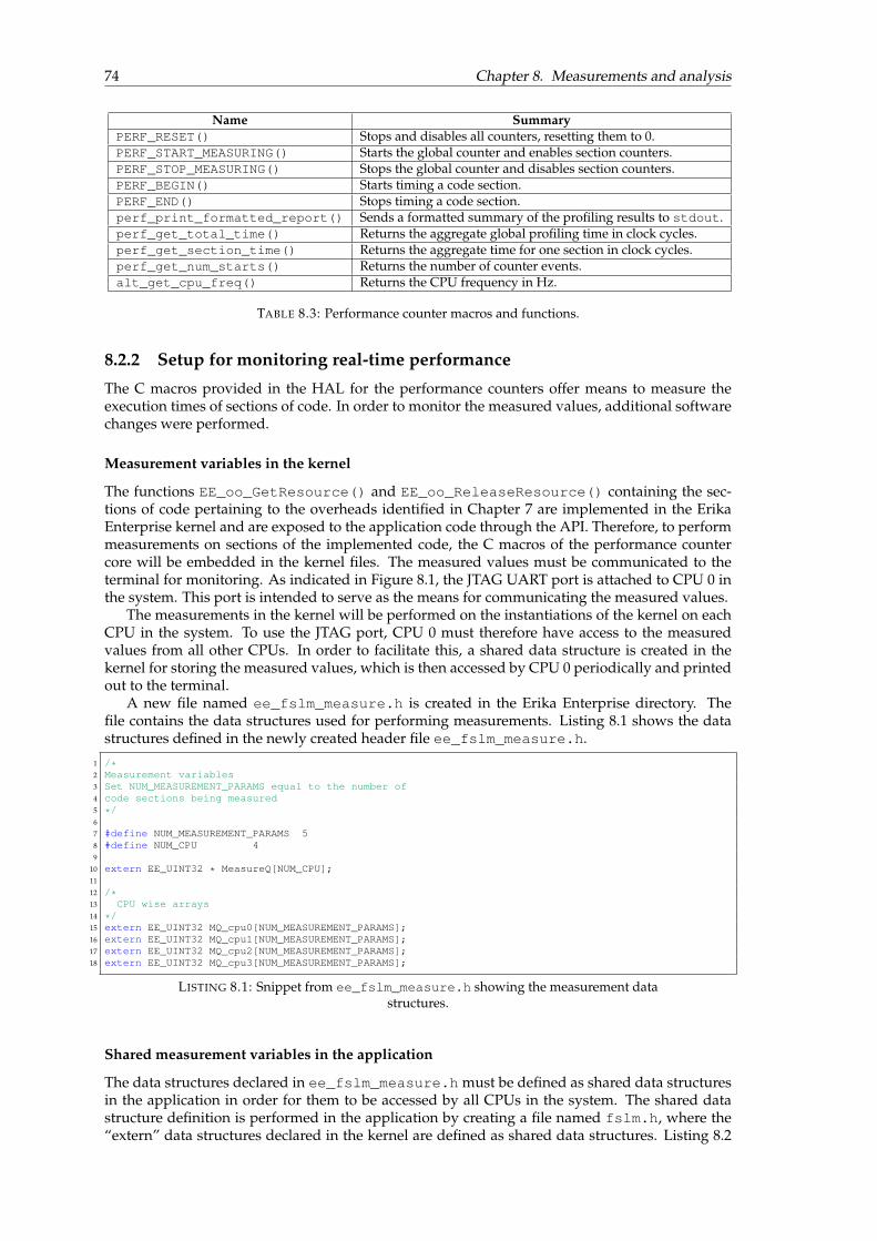
74 Chapter 8. Measurements and analysis
Name SummaryPERF_RESET() Stops and disables all counters, resetting them to 0.PERF_START_MEASURING() Starts the global counter and enables section counters.PERF_STOP_MEASURING() Stops the global counter and disables section counters.PERF_BEGIN() Starts timing a code section.PERF_END() Stops timing a code section.perf_print_formatted_report() Sends a formatted summary of the profiling results to stdout.perf_get_total_time() Returns the aggregate global profiling time in clock cycles.perf_get_section_time() Returns the aggregate time for one section in clock cycles.perf_get_num_starts() Returns the number of counter events.alt_get_cpu_freq() Returns the CPU frequency in Hz.
TABLE 8.3: Performance counter macros and functions.
8.2.2 Setup for monitoring real-time performance
The C macros provided in the HAL for the performance counters offer means to measure theexecution times of sections of code. In order to monitor the measured values, additional softwarechanges were performed.
Measurement variables in the kernel
The functions EE_oo_GetResource() and EE_oo_ReleaseResource() containing the sec-tions of code pertaining to the overheads identified in Chapter 7 are implemented in the ErikaEnterprise kernel and are exposed to the application code through the API. Therefore, to performmeasurements on sections of the implemented code, the C macros of the performance countercore will be embedded in the kernel files. The measured values must be communicated to theterminal for monitoring. As indicated in Figure 8.1, the JTAG UART port is attached to CPU 0 inthe system. This port is intended to serve as the means for communicating the measured values.
The measurements in the kernel will be performed on the instantiations of the kernel on eachCPU in the system. To use the JTAG port, CPU 0 must therefore have access to the measuredvalues from all other CPUs. In order to facilitate this, a shared data structure is created in thekernel for storing the measured values, which is then accessed by CPU 0 periodically and printedout to the terminal.
A new file named ee_fslm_measure.h is created in the Erika Enterprise directory. Thefile contains the data structures used for performing measurements. Listing 8.1 shows the datastructures defined in the newly created header file ee_fslm_measure.h.
1 /*2 Measurement variables3 Set NUM_MEASUREMENT_PARAMS equal to the number of4 code sections being measured5 */6
7 #define NUM_MEASUREMENT_PARAMS 58 #define NUM_CPU 49
10 extern EE_UINT32 * MeasureQ[NUM_CPU];11
12 /*13 CPU wise arrays14 */15 extern EE_UINT32 MQ_cpu0[NUM_MEASUREMENT_PARAMS];16 extern EE_UINT32 MQ_cpu1[NUM_MEASUREMENT_PARAMS];17 extern EE_UINT32 MQ_cpu2[NUM_MEASUREMENT_PARAMS];18 extern EE_UINT32 MQ_cpu3[NUM_MEASUREMENT_PARAMS];
LISTING 8.1: Snippet from ee_fslm_measure.h showing the measurement datastructures.
Shared measurement variables in the application
The data structures declared in ee_fslm_measure.h must be defined as shared data structuresin the application in order for them to be accessed by all CPUs in the system. The shared datastructure definition is performed in the application by creating a file named fslm.h, where the“extern” data structures declared in the kernel are defined as shared data structures. Listing 8.2

8.2. Software setup 75
shows the snippet from fslm.h in the application level where the data structures are definedas shared. From Line 13 of Listing 8.2, it can be seen that MeasureQ is a shared 2 dimensionalinteger array that has NUM_CPU× NUM_MEASUREMENT_PARAMS elements.
1 extern EE_UINT32 MQ_cpu0[NUM_MEASUREMENT_PARAMS];2 extern EE_UINT32 MQ_cpu1[NUM_MEASUREMENT_PARAMS];3 extern EE_UINT32 MQ_cpu2[NUM_MEASUREMENT_PARAMS];4 extern EE_UINT32 MQ_cpu3[NUM_MEASUREMENT_PARAMS];5
6 EE_UINT32 EE_SHARED_DATA(MQ_cpu0)[NUM_MEASUREMENT_PARAMS];7 EE_UINT32 EE_SHARED_DATA(MQ_cpu1)[NUM_MEASUREMENT_PARAMS];8 EE_UINT32 EE_SHARED_DATA(MQ_cpu2)[NUM_MEASUREMENT_PARAMS];9 EE_UINT32 EE_SHARED_DATA(MQ_cpu3)[NUM_MEASUREMENT_PARAMS];
10
11 extern EE_UINT32 * MeasureQ[NUM_CPU];12
13 EE_UINT32 * const EE_SHARED_DATA(MeasureQ)[NUM_CPU] = {14 MQ_cpu0,15 MQ_cpu1,16 MQ_cpu2,17 MQ_cpu3,18 };
LISTING 8.2: Snippet from fslm.h showing the measurement data structures.
Initializing the shared measurement variables
The measurement data structure needs to be initialized during the system startup. Since CPU 0 isdefined as the master CPU, the initialization is performed in the application code of CPU 0. List-ing 8.3 shows the snippet from cpu0_main.c where all the values in MeasureQ are initializedto 0 during the system startup.
1 for(i=0; i<NUM_CPU; i++){2 for(j=0; j<NUM_MEASUREMENT_PARAMS; j++){3 EE_SHARED_DATA_MeasureQ[i][j] = 0x00;4 }5 }
LISTING 8.3: Snippet from cpu0_main.c showing the initialization of MeasureQ.
Monitoring the values
While the system is running, CPU 0 is also in-charge of periodically printing the contents ofMeasureQ to the terminal through the JTAG UART port for monitoring. Figure 8.2 shows a
FIGURE 8.2: Output of JTAG UART port from CPU 0 on the terminal.
sample output from the terminal produced while listening on the JTAG UART port of CPU 0. Theinformation from the terminal provides the execution time of the overheads measured duringruntime. The information is analyzed as follows:
• The value “66” occurs as the 4th element (index = 3) in the MeasureQ of CPU 1. From List-ing 8.5, it can be seen that index 3 corresponds to the EE_di_send() function. Thus thehex-value “66” corresponds to 102 cycles, representing the execution time of EE_di_send()function, i.e, OHDI
snd.
• Similarly the value “f3” occurs as the 3rd element (index = 2) in the MeasureQ of CPU 2.From Listing 8.5, it can be seen that index 2 corresponds to OHDI
hdl. Thus the hex-value “f3”corresponds to 243 cycles, representing the execution time of OHDI
hdl.

76 Chapter 8. Measurements and analysis
The use of a dedicated core (CPU 0) to communicate the measured values eliminates any influ-ence on the measured values due to the measurement setup. As an alternative, the measurementvalues can also be stored in the global memory and output at the end of the execution. But thismethod may lead to overflowing global memory for longer periods of execution while presentingno significant advantage over the presented method of rewriting a predetermined set of measure-ment values during the execution while using a dedicated core to read and periodically outputthe values.
8.2.3 Code instrumentation
The actual code instrumentation performed to mark the beginning and end of the sections ofcode to be measured is presented in this section. Using the performance counter core API func-tions listed in Table 8.3, the parts of the code identified as overhead components in Chapter 7.2are instrumented. Listing 8.4 shows the measurement of the overhead OHDI
snd in the functionEE_hal_spin_out() (which calls EE_di_send()) using the performance counter core 1. Line 21shows that section 0 of performance counter core 1 is being used for the measurement. It canalso be noted that since OHDI
snd occurs during the measurement of OHRL,Gadm , the measurement of
OHRL,Gadm is paused and resumed in Lines 14 and 40 respectively . In Line 35, it can be seen that the
value of the counter is written to the corresponding element in MeasureQ.1 __INLINE__ void __ALWAYS_INLINE__ EE_hal_spin_out(EE_TYPESPIN m){2
3 EE_UINT32 task2notify=0;4
5 EE_altera_mutex_spin_in();6 task2notify=ResourceQ[m][EE_CURRENTCPU];7 ResourceQ[m][EE_CURRENTCPU]=0xa0;8 EE_altera_mutex_spin_out();9
10 if(task2notify!=GlobalTaskID[EE_stkfirst]){11
12 /*------Stop measuring Rel admin overhead--*/13 #ifdef MF_REL_ADMIN14 PERF_END(PERFORMANCE_COUNTER_1_BASE,0);15 #endif16
17 /*------Start measuring DI send overhead---*/18 #ifdef MF_INTR_SEND19 PERF_RESET(PERFORMANCE_COUNTER_1_BASE);20 PERF_START_MEASURING(PERFORMANCE_COUNTER_1_BASE);21 PERF_BEGIN(PERFORMANCE_COUNTER_1_BASE,0);22 #endif23
24
25 /*------The section that is measured-------*/26 register EE_TYPERN_PARAM par;27 par.pending = 1;28 EE_di_send(task2notify);29 /*-----------------------------------------*/30
31 #ifdef MF_INTR_SEND32 PERF_END(PERFORMANCE_COUNTER_1_BASE,0);33 PERF_STOP_MEASURING(PERFORMANCE_COUNTER_1_BASE);34 MeasureQ[EE_CURRENTCPU][MF_INTR_SEND] = \35 perf_get_section_time((void *)PERFORMANCE_COUNTER_1_BASE, 0);36 #endif37
38 /*------Resume measuring Rel admin overhead--*/39 #ifdef MF_REL_ADMIN40 PERF_BEGIN(PERFORMANCE_COUNTER_1_BASE,0);41 #endif42 }43 }
LISTING 8.4: Snippet of EE_hal_spin_out() showing the code instrumentationfor measurement of OHDI
snd.
It can be observed from Listing 8.4 that the measurement related code instrumentation isguarded by the macro MF_INTR_SEND. A set of such macros corresponding to each type of over-head are defined in the file ee_fslm_measure.h to provide control over the sections of codethat are being measured. By commenting and uncommenting the different macros, it is possibleto include or exclude sections of code from being profiled. Listing 8.5 shows the definition of themacros. The comments specify the performance counter core ID and the section counter ID thateach of the sections use. The user must ensure that no two macros that use the same performance
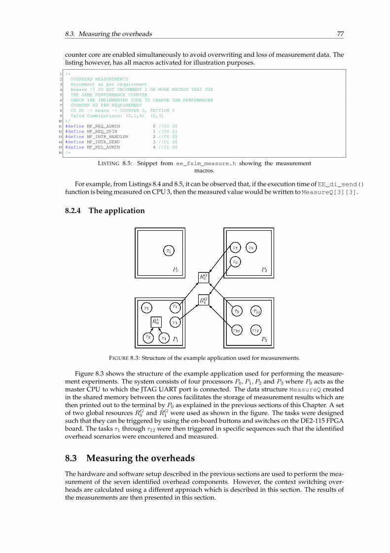
8.3. Measuring the overheads 77
counter core are enabled simultaneously to avoid overwriting and loss of measurement data. Thelisting however, has all macros activated for illustration purposes.
1 /*2 OVERHEAD MEASUREMENTS3 Uncomment as per requirement4 Beware !! DO NOT UNCOMMENT 2 OR MORE MACROS THAT USE5 THE SAME PERFORMANCE COUNTER6 CHECK THE IMPLEMENTED CODE TO CHANGE THE PERFORMACNE7 COUNTER AS PER REQUIREMENT8 C0 S0 -> means -> COUNTER 0, SECTION 09 Valid Combinations: (0,1,4) (2,3)
10 */11 #define MF_REQ_ADMIN 0 //C0 S012 #define MF_REQ_SPIN 1 //C0 S113 #define MF_INTR_HANDLER 2 //C0 S014 #define MF_INTR_SEND 3 //C1 S015 #define MF_REL_ADMIN 4 //C1 S016 /*
LISTING 8.5: Snippet from ee_fslm_measure.h showing the measurementmacros.
For example, from Listings 8.4 and 8.5, it can be observed that, if the execution time of EE_di_send()function is being measured on CPU 3, then the measured value would be written to MeasureQ[3][3].
8.2.4 The application
FIGURE 8.3: Structure of the example application used for measurements.
Figure 8.3 shows the structure of the example application used for performing the measure-ment experiments. The system consists of four processors P0, P1, P2 and P3 where P0 acts as themaster CPU to which the JTAG UART port is connected. The data structure MeasureQ createdin the shared memory between the cores facilitates the storage of measurement results which arethen printed out to the terminal by P0 as explained in the previous sections of this Chapter. A setof two global resources RG0 and RG1 were used as shown in the figure. The tasks were designedsuch that they can be triggered by using the on-board buttons and switches on the DE2-115 FPGAboard. The tasks τ1 through τ12 were then triggered in specific sequences such that the identifiedoverhead scenarios were encountered and measured.
8.3 Measuring the overheads
The hardware and software setup described in the previous sections are used to perform the mea-surement of the seven identified overhead components. However, the context switching over-heads are calculated using a different approach which is described in this section. The results ofthe measurements are then presented in this section.

78 Chapter 8. Measurements and analysis
8.3.1 Context switching overheads
The context switching code segments in Erika are implemented in assembly language. Hence,the C macros used for annotating the sections of code to be measured cannot be used for thesesections of code implemented in assembly language. The context switching overheads OHDI
bcs andOHDI
cs were calculated using the CPU performance equation [46]:
CPU cstime = IC × CPI × Tcycle, (8.1)
where CPU cstime is the execution time of the program being measured (context switching code
section in this case), IC is the number of instructions in the program being measured, CPI is theaverage number of cycles per instruction and Tcycle is the time per cycle.
For the system under consideration, the number of instructions (IC) in the assembly codepertaining to context switching was found to be 41. Since the frequency of the clock used is50MHz, the value of Tcycle = 20ns. To calculate CPI , the composition of the types of instructionsis analyzed. The Altera instruction set manual for Nios II core [47] was used to determine thecomposition, which was found to be as presented in Table 8.4.
Instructiontype
Percentagecomposition Cycles
Load 29% 5Store 29% 4R-type 35% 4I-type 5% 3J-type 2% 3
TABLE 8.4: CPI calculation for context switching overheads
R-type instructions are used when the required data values are located in the CPU registers ordata values are to be written to the CPU registers. I-type instructions have an immediate operandand J-type instructions are used when jumps are required. Since the system uses a 32-bit RISCsub-scalar (no pipelining) processor, the CPI is calculated as follows:
CPI =(5× 29) + (4× 29) + (4× 35) + (3× 5) + (3× 2)
100= 4.22
Using (8.1), CPU cstime was calculated as 3.44µs. In terms of number of clock cycles (CPU cs
cycles),
CPU cscycles = dIC × CPIe
= 173 cycles
Since the same section of assembler code is called for both OHDIbcs and OHDI
cs , the executiontime in terms of number of cycles for both the overheads is equal to 173 cycles.
8.3.2 Measurement results
The measured overheads in the implementations of MSRP (native Erika Enterprise implementa-tion), the old implementation of FSLM [3] and the new implementation of FSLM developed forthis project are summarized in Table 8.5.
The experiments were repeated 50 times on each core and the table shows the mean and max-imum values along with the standard deviation (SD) from the obtained data for each of the over-heads. A significant reduction in OHDI
hdl and OHDIsnd over the old implementation [3] can be ob-
served in the new implementation of FSLM developed for this project.The relative sizes of the cumulative overheads (sum of all individual overhead components)
in the three implementations are visualized in Figure 8.4. It can be observed from the figure thatthe overall decrease in the execution time of overheads in the new implementation of FSLM whencompared to the old implementation [3] is 57.22%.
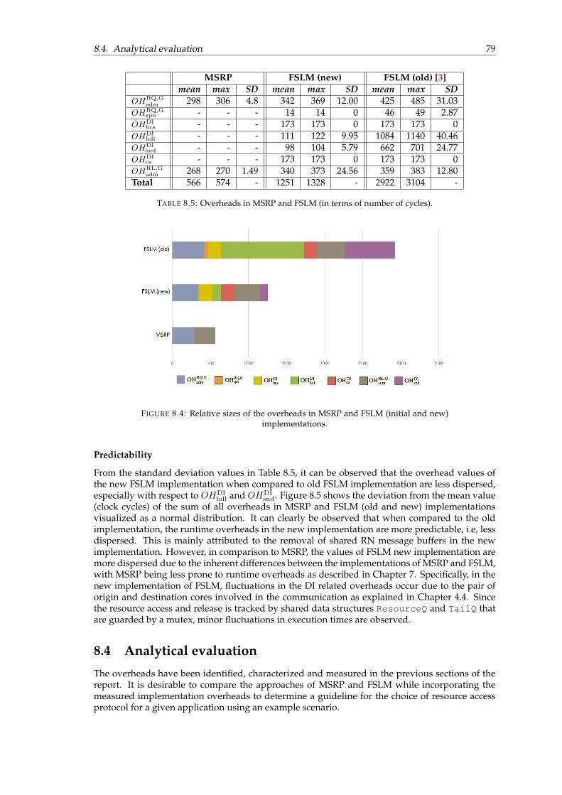
8.4. Analytical evaluation 79
MSRP FSLM (new) FSLM (old) [3]mean max SD mean max SD mean max SD
OHRQ,Gadm 298 306 4.8 342 369 12.00 425 485 31.03
OHRQ,Gspn - - - 14 14 0 46 49 2.87
OHDIbcs - - - 173 173 0 173 173 0
OHDIhdl - - - 111 122 9.95 1084 1140 40.46
OHDIsnd - - - 98 104 5.79 662 701 24.77
OHDIcs - - - 173 173 0 173 173 0
OHRL,Gadm 268 270 1.49 340 373 24.56 359 383 12.80
Total 566 574 - 1251 1328 - 2922 3104 -
TABLE 8.5: Overheads in MSRP and FSLM (in terms of number of cycles).
FIGURE 8.4: Relative sizes of the overheads in MSRP and FSLM (initial and new)implementations.
Predictability
From the standard deviation values in Table 8.5, it can be observed that the overhead values ofthe new FSLM implementation when compared to old FSLM implementation are less dispersed,especially with respect to OHDI
hdl and OHDIsnd. Figure 8.5 shows the deviation from the mean value
(clock cycles) of the sum of all overheads in MSRP and FSLM (old and new) implementationsvisualized as a normal distribution. It can clearly be observed that when compared to the oldimplementation, the runtime overheads in the new implementation are more predictable, i.e, lessdispersed. This is mainly attributed to the removal of shared RN message buffers in the newimplementation. However, in comparison to MSRP, the values of FSLM new implementation aremore dispersed due to the inherent differences between the implementations of MSRP and FSLM,with MSRP being less prone to runtime overheads as described in Chapter 7. Specifically, in thenew implementation of FSLM, fluctuations in the DI related overheads occur due to the pair oforigin and destination cores involved in the communication as explained in Chapter 4.4. Sincethe resource access and release is tracked by shared data structures ResourceQ and TailQ thatare guarded by a mutex, minor fluctuations in execution times are observed.
8.4 Analytical evaluation
The overheads have been identified, characterized and measured in the previous sections of thereport. It is desirable to compare the approaches of MSRP and FSLM while incorporating themeasured implementation overheads to determine a guideline for the choice of resource accessprotocol for a given application using an example scenario.

80 Chapter 8. Measurements and analysis
FIGURE 8.5: Predictability of the cumulative overheads in MSRP, FSLM (old andnew).
8.4.1 Analysis scenario
This section contains the description of the example scenario used for the analytical evaluation.The goal of the analysis is to study the effects of worst-case local and remote blocking on a highpriority task that does not use any global resources. The analysis is performed for MSRP, FSLM-CP and FSLM-HP approaches. The values of implementation overheads measured for the newimplementation of FSLM and the native implementation of MSRP are used in the calculations.
Consider a system with m processors P0, P1, .., Pm−1. Tasks {τhp, τcp} are mapped on to Pm−1while tasks τ0, τ1, .., τm−2 are mapped on to P0, P1, .., Pm−2 respectively. All tasks except τhp re-quire access to a shared global resource Rq and are identical to each other in terms of globalresource usage with their global critical section (gcs) occurring after a non-critical section whichis of the same length for all tasks.
The tasks τ0, τ1, .., τm−2 and τcp request the global resource within an infinitesimally smalltime ε in such a way that τ0 always accesses the resource first, followed by τ1 and so on andthen finally by τcp. On processor Pm−1, the high priority task τhp is set to activate at the instantwhen τcp makes the resource request. Since the resource request sections of the code are executednon-preemptively, RQ2 is always encountered by τhp . This setup can be adopted to anywherebetween 2 to 16 processors to perform the analysis τhp. Figures 8.6a and 8.6b show the abovesetup for a system with 3 processors for FSLM-HP and FSLM-CP approaches respectively.
Goal
The objective of the analysis is to observe the response time of the highest priority task τhp byvarying the global critical section (gcs) lengths of all the remaining tasks in the system underMSRP, FSLM-HP and FSLM-CP approaches while taking into account the measured implemen-tation overheads.
Constants
The following parameters are maintained constant throughout the analysis for FSLM:
i) Computation time of τhp, Chp = 5000 cycles (100µs at 50MHz)
ii) ∀i:(0≤i≤m−2)∧cp
CNCSi = 3000 cycles (60µs at 50MHz)

8.4. Analytical evaluation 81
(A) FSLM-HP. (B) FSLM-CP.
FIGURE 8.6: Analytical evaluation scenario.
iii) RQ1 = OHRQ,Gadm = 369 cycles
iv) RQ2 = RQ1 + OHRQ,Gspn = 383 cycles
v) AC1 = OHDIhdl = 122 cycles
vi) AC2 = AC1 + OHDIcs = 295 cycles
vii) RL1 = OHRL,Gadm = 373 cycles
viii) RL2 = RL1 + OHDIsnd = 477 cycles
And for MSRP:
i) OHRQ,Gadm = 306 cycles
ii) OHRL,Gadm = 270 cycles
It can be noted that all the maximum values from the obtained overhead measurement resultsin Table 8.5 has been used in the analysis. All overheads except OHDI
bcs are encountered as a partof the analysis scenario. Although OHDI
cs is not shown in Figure 8.6b, it will be encountered whenthe resource access is granted to τcp before the completion of τhp.
Variables
The following parameters are varied for performing the analysis:
i) The number of processors m.
ii) For each system ofm processors, the values of global critical section (gcs) lengths of all tasksin the system are varied uniformly between 5 and 4000 cycles (0.1 to 80µs at 50 MHz).
8.4.2 Analysis results
The results of the analysis under different conditions are presented in this section. It is to be notedthat the presented results and interpretations are specific to the scenario illustrated in Section 8.4.1and to the implementations of MSRP and FSLM (new) on Erika Enterprise as instantiated onthe Altera DE2-115 FPGA platform. Thus, the values do not necessarily reflect the worst-case

82 Chapter 8. Measurements and analysis
response times of the highest priority task but just represent the response times under the scenarioconsidered. Although conceptually, the findings can be generalized to MSRP and FSLM, thevalues of overheads represented in the scenario are characteristic of the platform used for thisstudy.
2 Processors
The analysis is initially performed with m = 2 with tasks τ0 in P0 and {τcp, τhp} in P1. Theresponse time of τhp plotted as a function of varying gcs lengths of tasks τ0 and τcp is shown inFigure 8.7.
FIGURE 8.7: The response time of τhp as a function of the gcs lengths of lowerpriority and remote tasks under MSRP, FSLM-CP and FSLM-HP with 2 processors.
The following observations can be made from the plot in Figure 8.7. All the time measure-ments are calculated from the number of clock cycles at 50 MHz clock frequency.
i) MSRP results in better response times for τhp than FSLM-CP for gcs lengths less than 310cycles (6.20µs).
ii) For gcs lengths greater than 310 cycles, FSLM-CP gives better response times for τhp thanMSRP. The relative improvement in response time of τhp in FSLM-CP over MSRP becomesmore pronounced as the gcs length increases further.
iii) The response time of τhp under FSLM-HP is observed to be parallel to MSRP. This is justifiedsince conceptually MSRP and FSLM-HP are identical, but the implementation of FSLM-HPincurs additional overheads that are not part of MSRP.
iv) MSRP and FSLM-CP always outperform FSLM-HP in terms of the response time of τhp forall gcs lengths under the given analysis scenario.
Due to the fact that under the given scenario, FSLM-CP outperforms MSRP for response timeof τhp for gcs lengths above 310 cycles, it is possible to create task sets that are schedulable by FSLM-CP but not by MSRP. For instance, consider the task set proposed in Example 6.
Example 6. For a system with tasks τ0 in P0 and {τcp, τhp} in P1, assume a gcs length of 2500 cycles(50µs) for tasks τ0 and τcp. The response time for the task τhp using FSLM-CP would be 2190 cycles(43.80µs) faster than MSRP. A relative deadline Dhp = 10000 cycles (200µs) for τhp would cause adeadline miss by 16.90µs in MSRP while FSLM-CP would complete the execution of 26.90µs before thedeadline.
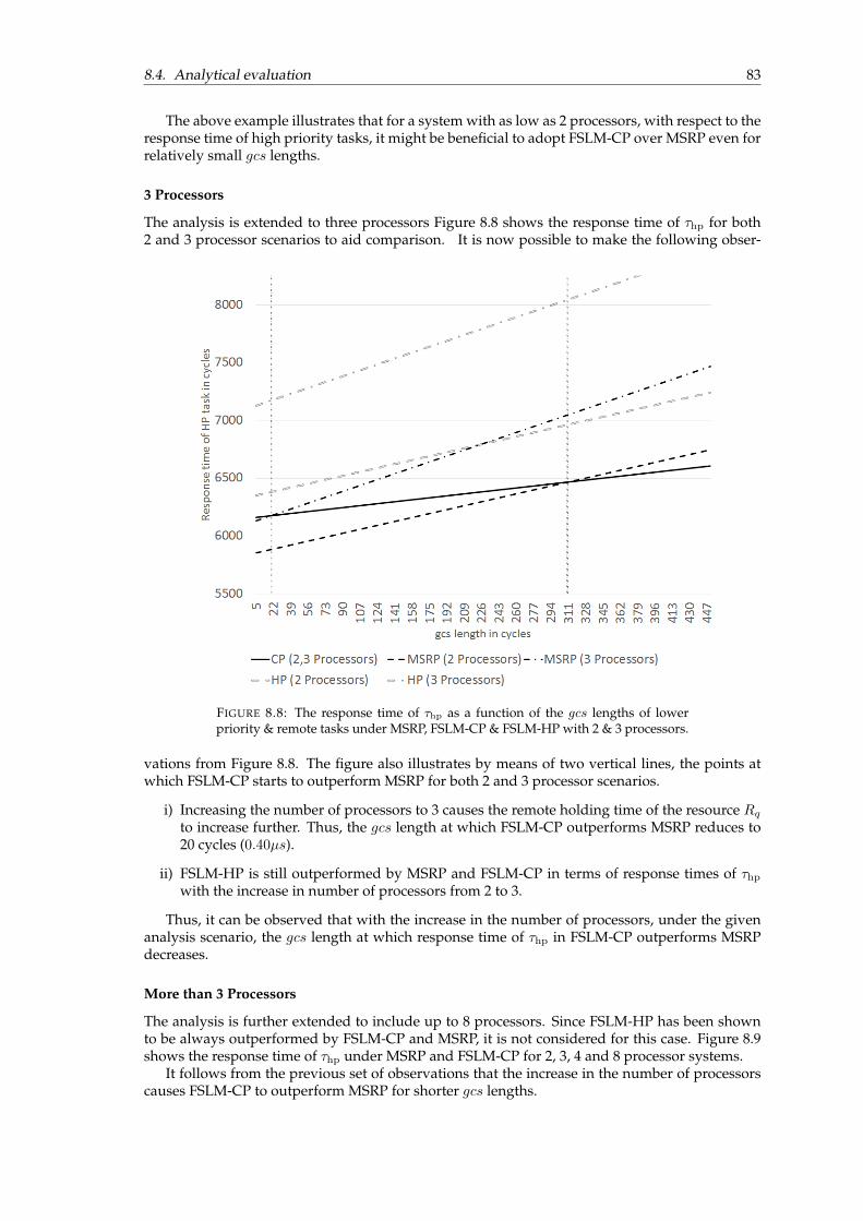
8.4. Analytical evaluation 83
The above example illustrates that for a system with as low as 2 processors, with respect to theresponse time of high priority tasks, it might be beneficial to adopt FSLM-CP over MSRP even forrelatively small gcs lengths.
3 Processors
The analysis is extended to three processors Figure 8.8 shows the response time of τhp for both2 and 3 processor scenarios to aid comparison. It is now possible to make the following obser-
FIGURE 8.8: The response time of τhp as a function of the gcs lengths of lowerpriority & remote tasks under MSRP, FSLM-CP & FSLM-HP with 2 & 3 processors.
vations from Figure 8.8. The figure also illustrates by means of two vertical lines, the points atwhich FSLM-CP starts to outperform MSRP for both 2 and 3 processor scenarios.
i) Increasing the number of processors to 3 causes the remote holding time of the resource Rqto increase further. Thus, the gcs length at which FSLM-CP outperforms MSRP reduces to20 cycles (0.40µs).
ii) FSLM-HP is still outperformed by MSRP and FSLM-CP in terms of response times of τhpwith the increase in number of processors from 2 to 3.
Thus, it can be observed that with the increase in the number of processors, under the givenanalysis scenario, the gcs length at which response time of τhp in FSLM-CP outperforms MSRPdecreases.
More than 3 Processors
The analysis is further extended to include up to 8 processors. Since FSLM-HP has been shownto be always outperformed by FSLM-CP and MSRP, it is not considered for this case. Figure 8.9shows the response time of τhp under MSRP and FSLM-CP for 2, 3, 4 and 8 processor systems.
It follows from the previous set of observations that the increase in the number of processorscauses FSLM-CP to outperform MSRP for shorter gcs lengths.

84 Chapter 8. Measurements and analysis
FIGURE 8.9: The response time of τhp as a function of the gcs lengths of lowerpriority and remote tasks under MSRP and FSLM-CP with 2, 3, 4 and 8 processors.
i) For a system with 4 processors, FSLM-CP outperforms MSRP for all gcs lengths under theconsidered analysis scenario.
ii) For an 8 processor system, the difference in response times between MSRP and FSLM-CP isvery significant as seen in Figure 8.9. The increased remote holding time causes the responsetime in MSRP to increase while FSLM-CP allows for the completion of τhp while τcp waitsfor the resource. Due to the analysis scenario considered, FSLM-CP delivers a best caseresponse time of 5383 cycles for τhp since it always incurs RQ2.
Thus, in summary, it can be concluded that for the analysis scenario considered, the responsetime of the high priority task is significantly better under FSLM-CP when compared to MSRP asthe number of processors in the system increases.

85
Chapter 9
Low-level hardware locks
The underlying RTOS in a multiprocessor system on which any application is built uses low-levelhardware locks (mutex) to facilitate exclusive access to resources among competing entities. Inthis chapter, the effects of such low-level hardware locks on the performance of the applicationare investigated with respect to the FSLM implementation on Erika Enterprise RTOS.
9.1 Hardware mutex options in Erika
In the hardware configuration of a multiprocessor system for the Nios II platform, an AlteraAvalon Mutex Peripheral is required by Erika Enterprise according to [27]. Hence, in the hard-ware design phase of the system, a mutex peripheral connected to all four cores in the system wascreated as shown in Figure 9.1.
FIGURE 9.1: Hardware definition of mutex peripheral.
The base address of the defined Altera HAL mutex device is auto-generated at the end of thehardware design synthesis in the system library within the file system.h. The base address ofthe mutex must be specified in the OIL file using the parameter NIOS2_MUTEX_BASE as a part ofthe OS object. Currently, Erika supports the specification of only one mutex device. The potentialdrawbacks of this approach are further investigated in this chapter.
Usage of the mutex device in the OS
Any section of code requiring the modification of a data structure that is shared across multiplecores is typically accessed under mutual exclusion. The functions EE_altera_mutex_spin_in()and EE_altera_mutex_spin_out() defined in the kernel layer of Erika are used to enclose thesection of code that has to be executed under mutual exclusion. The above functions are used toacquire and release the low-level hardware mutex respectively.
For example, in the FSLM implementation, the data structures ResourceQ and TailQ areshared among all the processors in the system and hence require mutual exclusive access in orderto be modified. Listing 9.1 shows the definition of the function EE_hal_spin_out() that iscalled during resource release. The value in ResourceQ has to be updated to signal that theresource has been released. It can be seen that in Line 9, the update of ResourceQ is enclosedwithin the calls to acquire and release the hardware mutex. This ensures that the shared variableis always modified by at most one core at any given time under mutual exclusion.

86 Chapter 9. Low-level hardware locks
1
2 __INLINE__ void __ALWAYS_INLINE__ EE_hal_spin_out(EE_TYPESPIN m){3
4 EE_UINT32 task2notify=0;5 task2notify=ResourceQ[m][EE_CURRENTCPU];6
7 // Update the release of the resource8 EE_altera_mutex_spin_in();9 ResourceQ[m][EE_CURRENTCPU]=0xa0;
10 EE_altera_mutex_spin_out();11
12 if(task2notify!=GlobalTaskID[EE_stkfirst]){13 register EE_TYPERN_PARAM par;14 par.pending = 1;15 EE_di_send(task2notify);16 }17 }
LISTING 9.1: Snippet section guarded by mutex in EE_hal_spin_out().
9.2 Drawback of using one mutex device for the system
Although the use of a mutex device in Erika guarantees mutual exclusive access to shared datastructures, the presence of only one such device may act as a bottleneck under certain situations.This section explores one such scenario in which it might be beneficial to have support for morethan one hardware mutex device.
9.2.1 Existing scenario
Example 7. Consider a simple two processor system with processors P0 and P1. Let the tasks {τ0, τ1} bemapped on to P0 while {τ2, τ3} are mapped on to P1. There are two global shared resources R0 and R1
with tasks τ0, τ2 accessing R0 and tasks τ1, τ3 accessing R1.
Consider a system as described in Example 7. Unlike the FSLM implementation used for thestudy, assume that instead of a ResourceQ variable that is defined as a 2 dimensional array, thesystem consists of individual one dimensional arrays for every resource in the system, where eacharray has m elements where m is the number of processors in the system. Hence, for the scenariomentioned in Example 7, assume that the following shared data structures exist instead of a singletwo dimensional ResourceQ array:
i) ResourceQ_R0[2] - Resource queue for R0 with two elements, one for each core.
ii) ResourceQ_R1[2] - Resource queue for R1 with two elements, one for each core.
Under the given scenario, let the task τ0 in P0 and τ3 in P1 issue simultaneous resource requestsfor R0 and R1 respectively. This situation triggers the following set of events:
1. Although tasks τ0 and τ3 require access to different data structures in the global memory, allshared data structures are protected by the same hardware mutex.
2. Both the tasks τ0 and τ3 try to acquire the mutex simultaneously as shown in Figure 9.2a.
3. The access to low-level hardware mutex is not ordered. Hence any of the competing tasksmay acquire the mutex first. In this example, assume τ0 acquires the mutex first and pro-ceeds to modify ResourceQ_R0[P0] while the task τ3 is forced to wait for the mutex tobecome available as shown in Figure 9.2b.
4. Upon completion of the modification of ResourceQ_R0[P0], the task τ0 releases the hard-ware mutex as shown in Figure 9.3a.
5. Task τ3 now acquires the mutex first and proceeds to modify ResourceQ_R1[P1]
It can be observed from this scenario that although τ0 and τ3 require access to different datastructures in the global memory, since both the data structures are protected by the same hardwaremutex, one of the tasks is always forced to wait for the other task to complete its mutual exclusiveaccess.

9.2. Drawback of using one mutex device for the system 87
(A) Both τ0 and τ3 try to acquirethe mutex.
(B) Task τ0 acquires the mutexwhile τ3 waits.
FIGURE 9.2: Using the same mutex for two unrelated shared data structures (steps1 and 2).
(A) Task τ0 releases the mutex. (B) Task τ3 acquires the mutex.
FIGURE 9.3: Using the same mutex for two unrelated shared data structures (steps3 and 4).
9.2.2 Alternative solution
The same scenario is explored under the condition that different shared data structures are nowprotected with separate hardware mutexes. Extreme care must be taken in such a scenario toensure that the appropriate data structures are always protected by the correct hardware mutexsince any failure to do so could result in race conditions. While using 2 hardware mutexes toprotect ResourceQ_R0 and ResourceQ_R1, the following series of events occur:
1. Both the tasks τ0 and τ3 try to access different shared data structures through protected bydifferent mutexes. From Figure 9.4a, it can now be seen that ResourceQ_R0 is protectedby MUTEX 0 while ResourceQ_R1 is protected by MUTEX 1.
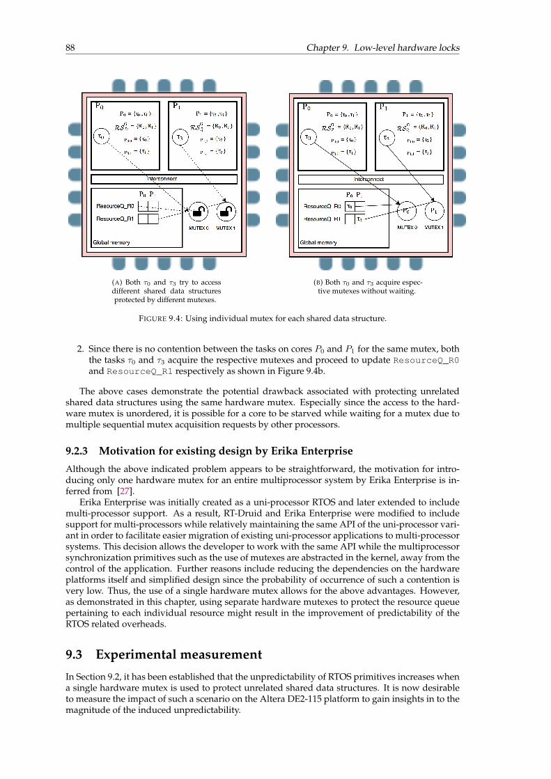
88 Chapter 9. Low-level hardware locks
(A) Both τ0 and τ3 try to accessdifferent shared data structuresprotected by different mutexes.
(B) Both τ0 and τ3 acquire espec-tive mutexes without waiting.
FIGURE 9.4: Using individual mutex for each shared data structure.
2. Since there is no contention between the tasks on cores P0 and P1 for the same mutex, boththe tasks τ0 and τ3 acquire the respective mutexes and proceed to update ResourceQ_R0and ResourceQ_R1 respectively as shown in Figure 9.4b.
The above cases demonstrate the potential drawback associated with protecting unrelatedshared data structures using the same hardware mutex. Especially since the access to the hard-ware mutex is unordered, it is possible for a core to be starved while waiting for a mutex due tomultiple sequential mutex acquisition requests by other processors.
9.2.3 Motivation for existing design by Erika Enterprise
Although the above indicated problem appears to be straightforward, the motivation for intro-ducing only one hardware mutex for an entire multiprocessor system by Erika Enterprise is in-ferred from [27].
Erika Enterprise was initially created as a uni-processor RTOS and later extended to includemulti-processor support. As a result, RT-Druid and Erika Enterprise were modified to includesupport for multi-processors while relatively maintaining the same API of the uni-processor vari-ant in order to facilitate easier migration of existing uni-processor applications to multi-processorsystems. This decision allows the developer to work with the same API while the multiprocessorsynchronization primitives such as the use of mutexes are abstracted in the kernel, away from thecontrol of the application. Further reasons include reducing the dependencies on the hardwareplatforms itself and simplified design since the probability of occurrence of such a contention isvery low. Thus, the use of a single hardware mutex allows for the above advantages. However,as demonstrated in this chapter, using separate hardware mutexes to protect the resource queuepertaining to each individual resource might result in the improvement of predictability of theRTOS related overheads.
9.3 Experimental measurement
In Section 9.2, it has been established that the unpredictability of RTOS primitives increases whena single hardware mutex is used to protect unrelated shared data structures. It is now desirableto measure the impact of such a scenario on the Altera DE2-115 platform to gain insights in to themagnitude of the induced unpredictability.

9.3. Experimental measurement 89
9.3.1 Measurement setup
The measurement setup described in Chapter 8 under Sections 8.1 and 8.2 is reused. However,since the experiment involves measurement of effects due to simultaneous requests to same hard-ware mutex, a few changes are made to the measurement setup.
Hardware addition
Since two tasks on different cores have to simultaneously access the same hardware mutex, man-ual triggering of tasks using buttons and switches will be inaccurate. Hence, the tasks are set tobe triggered by hardware timer units. “Interval timer” hardware units with a timer resolution of1 second were added to cores 1 and 2 in the existing hardware design as shown in Figure 9.5.
FIGURE 9.5: Interval timer hardware on cpu 1 and cpu 2.
Software additions in the application
To trigger the tasks based on the hardware timer signals, the alarm object alt_alarm is usedin the application. The hardware timers issue an interrupt every second since the resolution hasbeen set to 1 second. The alarm object can now be configured to activate the tasks in integralmultiples of 1 second. Listing 9.2 shows the snippet from CPU 1 for automatically activatingtask 3 once in every 10 seconds. The listing shows the definition of the alarm expiry callback,instantiation and activation of the alarm. Similar changes are made on CPU 2 to automaticallyactivate another task once in every 10 seconds. CPU 1 and CPU 2 will be used for performing theexperiment while CPU 0 will be used for printing the measured values to the terminal throughthe JTAG UART port.
1
2 // Define alarm expiry to 10 seconds3 #define TASK3_INTERVAL 10*alt_ticks_per_second()4
5 // Callback to be executed on alarm expiry6 alt_u32 Task3_alarm_callback (void* arg)7 {8 ActivateTask(task3);9 return TASK3_INTERVAL;
10 }11 int main(){12 //Declare the alarm13 alt_alarm task3Alarm;14
15 StartOS(1);16 //Start the alarm17 alt_alarm_start (&task3Alarm, TASK3_INTERVAL,18 Task3_alarm_callback, NULL);19
20 /*Rest of the main function*/21 }
LISTING 9.2: Snippet of example alarm initialization in cpu1_main.c.
CPU 1 and CPU 2 will be used for performing the experiment while CPU 0 will be used forprinting the measured values to the terminal through the JTAG UART port. Two identical taskson CPU 1 and CPU 2 are used for performing the measurements.
Software changes in the kernel
Due to the inherent inaccuracy of the two different timer hardwares in synchronizing with eachother, in order for the two tasks on different cores to request the mutex at the same time, the

90 Chapter 9. Low-level hardware locks
desired section of the code with the mutex request and release is executed multiple times to allowfor overlap to occur. For the purposes of the experiment, the following code snippet illustrated inListing 9.3 was added to the EE_oo_GetResource() function.
1 #ifdef MF_MUTEX2 int dummy = 0;3 int iter = 0;4
5 //Use performance counter 0 for core 16 //Use performance counter 1 for core 27 if(EE_CURRENTCPU == 1){8 PERF_RESET(PERFORMANCE_COUNTER_0_BASE);9 PERF_START_MEASURING(PERFORMANCE_COUNTER_0_BASE);
10 }11 else{12 PERF_RESET(PERFORMANCE_COUNTER_1_BASE);13 PERF_START_MEASURING(PERFORMANCE_COUNTER_1_BASE);14 }15
16 //Repeat acquisition and release of mutex 100000 times17
18 for(iter=0;iter<100000;iter++){19 if(EE_CURRENTCPU == 1){20 PERF_BEGIN(PERFORMANCE_COUNTER_0_BASE,0);21 }22 else{23 PERF_BEGIN(PERFORMANCE_COUNTER_1_BASE,0);24 }25 /*------The section that is measured-------*/26 EE_altera_mutex_spin_in();27 dummy++;28 EE_altera_mutex_spin_out();29 /*-----------------------------------------*/30 if(EE_CURRENTCPU == 1){31 PERF_END(PERFORMANCE_COUNTER_0_BASE,0);32 }33 else{34 PERF_END(PERFORMANCE_COUNTER_1_BASE,0);35 }36 }37
38 if(EE_CURRENTCPU == 1){39 PERF_STOP_MEASURING(PERFORMANCE_COUNTER_0_BASE);40 MeasureQ[EE_CURRENTCPU][0] = perf_get_section_time((void *)PERFORMANCE_COUNTER_0_BASE, 0);41 MeasureQ[EE_CURRENTCPU][1] = perf_get_num_starts((void *)PERFORMANCE_COUNTER_0_BASE, 0);42 MeasureQ[EE_CURRENTCPU][2] = dummy;43 }44 else{45 PERF_STOP_MEASURING(PERFORMANCE_COUNTER_1_BASE);46 MeasureQ[EE_CURRENTCPU][0] = perf_get_section_time((void *)PERFORMANCE_COUNTER_1_BASE, 0);47 MeasureQ[EE_CURRENTCPU][1] = perf_get_num_starts((void *)PERFORMANCE_COUNTER_1_BASE, 0);48 MeasureQ[EE_CURRENTCPU][2] = dummy;49 }50
51 #endif MF_MUTEX
LISTING 9.3: Mutex interference measurement code setup snippet.
The following features can be observed in the above listing:
• The snippet is added to the EE_oo_GetResource() function so that the section of code isexecuted every time a task tries to request a resource.
• Since this code is defined in the kernel and will be executed by different instantiations ofthe same code on different cores, it is not possible to use the same performance counter tomeasure the code section. This would result in both the cores using the same performancecounter thereby distorting the measurement values. Hence, as seen in the listing, the codeis instrumented such that any measurement by CPU 1 uses performance counter 0 whileany measurement by CPU 2 uses performance counter 1. By this way, two different corescan simultaneously measure the same code section using different performance counterswithout interference.
• To ensure sufficient overlap between CPU 1 and CPU 2 while executing the same section ofcode, the section of code with acquisition and release of mutex is repeated 100000 times.
• The section of code enclosed by the mutex is a simple increment statement. This is anal-ogous to most mutex protected code sections as they are typically restricted to making anupdate to a single shared data structure. It is not common to find long sections of codeguarded by the mutex.
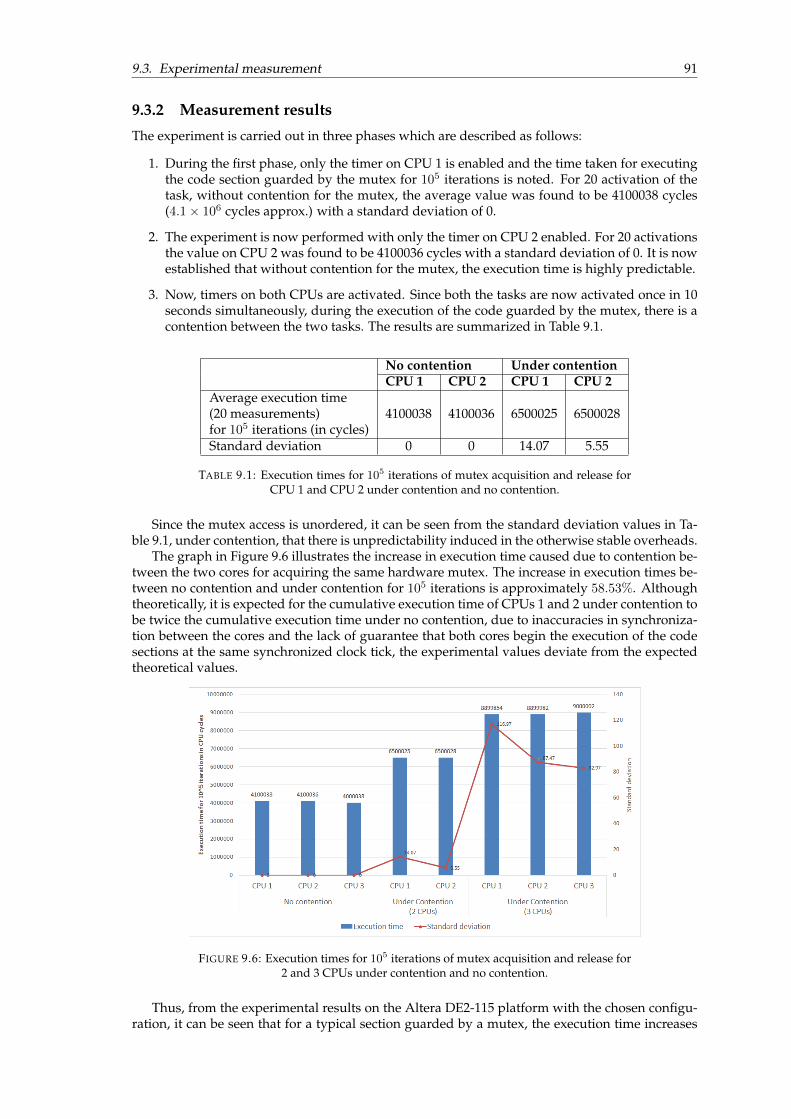
9.3. Experimental measurement 91
9.3.2 Measurement results
The experiment is carried out in three phases which are described as follows:
1. During the first phase, only the timer on CPU 1 is enabled and the time taken for executingthe code section guarded by the mutex for 105 iterations is noted. For 20 activation of thetask, without contention for the mutex, the average value was found to be 4100038 cycles(4.1× 10⁶ cycles approx.) with a standard deviation of 0.
2. The experiment is now performed with only the timer on CPU 2 enabled. For 20 activationsthe value on CPU 2 was found to be 4100036 cycles with a standard deviation of 0. It is nowestablished that without contention for the mutex, the execution time is highly predictable.
3. Now, timers on both CPUs are activated. Since both the tasks are now activated once in 10seconds simultaneously, during the execution of the code guarded by the mutex, there is acontention between the two tasks. The results are summarized in Table 9.1.
No contention Under contentionCPU 1 CPU 2 CPU 1 CPU 2
Average execution time(20 measurements)for 105 iterations (in cycles)
4100038 4100036 6500025 6500028
Standard deviation 0 0 14.07 5.55
TABLE 9.1: Execution times for 105 iterations of mutex acquisition and release forCPU 1 and CPU 2 under contention and no contention.
Since the mutex access is unordered, it can be seen from the standard deviation values in Ta-ble 9.1, under contention, that there is unpredictability induced in the otherwise stable overheads.
The graph in Figure 9.6 illustrates the increase in execution time caused due to contention be-tween the two cores for acquiring the same hardware mutex. The increase in execution times be-tween no contention and under contention for 105 iterations is approximately 58.53%. Althoughtheoretically, it is expected for the cumulative execution time of CPUs 1 and 2 under contention tobe twice the cumulative execution time under no contention, due to inaccuracies in synchroniza-tion between the cores and the lack of guarantee that both cores begin the execution of the codesections at the same synchronized clock tick, the experimental values deviate from the expectedtheoretical values.
FIGURE 9.6: Execution times for 105 iterations of mutex acquisition and release for2 and 3 CPUs under contention and no contention.
Thus, from the experimental results on the Altera DE2-115 platform with the chosen configu-ration, it can be seen that for a typical section guarded by a mutex, the execution time increases

92 Chapter 9. Low-level hardware locks
from 41 cycles per iteration to approximately 65 cycles per iteration under contention from onemore core. Since the probability of acquiring the mutex under contention between two cores un-der the considered experimental conditions is 0.5, we do not see starvation of one core by theother core as evidenced by almost equal overall execution times of CPUs 1 and 2.
The number of CPUs contending simultaneously for the same mutex device is now increasedto three. Table 9.2 shows the values obtained without and with contention during the experimentsfor 20 measurements each. The following observations can be made from the table:
No contention Under contentionCPU 1 CPU 2 CPU 3 CPU 1 CPU 2 CPU 3
Average execution time(20 measurements)for 105 iterations (in cycles)
4100038 4100036 4000038 8899854 8899982 9000002
Standard deviation 0 0 0 116.97 87.47 82.97
TABLE 9.2: Execution times for 105 iterations of mutex acquisition and release forCPUs 1, 2 and 3 under contention and no contention.
i) Under no contention, the average execution times for 105 iterations on CPU 3 is found tobe 4000038, which is almost 105 cycles less than the average values on CPUs 1 and 2. Thisindicates that every iteration on CPU 3 is 1 cycle faster than on CPUs 1 and 2. This could beattributed to the nature of the hardware platform.
ii) Under contention, the average execution times for 105 iterations on all 3 CPUs increasesto almost 9 million cycles, indicating an increase of between 117% and 124% with highestpercentage increase for CPU 3. This increase is also illustrated by the graph in Figure 9.6.
iii) The variation in the measured values are indicated by the standard deviation in the table.It can be observed that the standard deviation for 3 CPUs has significantly increased whencompared to the scenario with 2 CPUs presented in Table 9.1. This indicates that with anincrease in the number of CPUs contending for the mutex, not only the execution time in-creases, but it also becomes less predictable.
Thus, from the experiments, when there is a contention between three cores for a sectionguarded by the same hardware mutex, the average execution time per iteration increases from41 cycles to 90 cycles on CPUs 1 and 2 while it increases from 40 cycles to 92 cycles on CPU 3.
Hence, with the addition of multiple cores, it can be concluded that the performance and pre-dictability might become worse in case of contention, especially when subsequent mutex acqui-sitions by a core can potentially starve other cores due to the inherent unpredictability of mutexacquisition. However, since the probability of two or more cores executing calls to the mutex si-multaneously is extremely small, in order to avoid more complexity in the hardware design andto maintain the independence between the hardware platform and the operating system, in mostscenarios, it might be beneficial to still retain only one low-level mutex per system.

93
Chapter 10
Conclusions
In this thesis, a real-time multi-core system based on partitioned fixed-priority preemptive schedul-ing (P-FPPS) and a spin-based global resource access protocol (FSLM) for spin-priorities in [CP,HP] was considered. P-FPPS and spin-based protocols for multi-core systems are prescribed bystandards such as AUTOSAR [1]. The initial implementation of FSLM [3][4] in the OSEK/VDXcompliant RTOS Erika Enterprise on an Altera Nios II platform using 4 soft-core processors wasoptimized by making performance and memory related improvements. From a theoretical per-spective, i.e. by excluding runtime overheads, preemptive spin-based protocols, such as those de-scribed by FSLM, outperform non-preemptive protocols, such as MSRP. To make FSLM suitablefor the automotive domain, the runtime overheads introduced by FSLM were evaluated, dedi-cated terms were added to the schedulability analysis and the overheads were measured usingthe above platform. A comparison between the response times of tasks under FSLM and MSRPincluding runtime overheads were made and the results indicate that FSLM becomes particularlyattractive compared to MSRP when the critical section length of tasks accessing global sharedresources increases and the number of cores increases. Recommendations for further optimizingthe performance by exploring low-level RTOS mutual exclusion primitives were also provided.A detailed summary of the outcomes of the thesis and directions for future work are presented asconclusions.
10.1 Outcomes of the thesis
The outcomes of the thesis compared against the initial thesis goals (Chapter 1.4) are presented inthis section as a part of the conclusions.
1. Goal [I.1] was satisfied by creating the Dedicated Interrupt (DI) mechanism to replace theRN mechanism for the reduction of inter-core communication overheads as detailed inChapter 4. There was a significant reduction achieved in the overall inter-core commu-nication related overheads. This chapter also answers the research question 3 (Chapter 1.3)by showing that a dedicated interrupts mechanism is indeed feasible for spin-lock prioritiesin [CP, HP] while offering significantly better performance than the native RN mechanism.
2. Goal [I.2] involves the implementation of dual shared stacks per core for FSLM and to ex-plore the memory savings offered by the resulting implementation. This implementationhas been detailed in Chapter 5. The chapter answers research question 2 by showing thatthe implementation is feasible and provides a general formula for calculating the memorysaving by adopting the dual shared stacks method.
3. Goal [1.3] requires exploring the low-level hardware spin-lock usage in the RTOS. Chapter 9explores the Erika Enterprise RTOS hardware mutex usage and by means of experiments,establishes that guarding unrelated shared data structures using the same hardware mutexleads to bottlenecks and uncertainty in the RTOS overheads. The findings of the chaptersuggest that using a dedicated low-level hardware lock per resource can potentially reducesuch overheads, thereby answering research question 4.
4. Goals [M.1] and [M.2] have been satisfied as detailed in Chapter 8 by creating an elaboratesystem for measuring various sections of code in the platform. The overheads were thenidentified and measured using the measurement system.

94 Chapter 10. Conclusions
5. Goal [A.1] pertaining to the inclusion of overhead terms in the schedulability analysis ofFSLM has been addressed in Chapter 7. Overheads have been included in the analysis ofMSRP as well as the two main spin-lock approaches of FSLM namely CP and HP. A genericmethod for classifying the RAP related overheads has been presented which can be appliedwith minor modifications to any RAP implementation. Analytical comparisons were thenpresented showing that with an increase in number of processors, in-spite of overheads,FSLM-CP outperforms MSRP with respect to the response times of high priority tasks in thesystem, thereby answering research question 1.
6. Goals [D.1] and [D.2] have been satisfied in the form of this thesis document and the in-cluded Appendices.
7. Goal [D.3] was to submit parts of the findings from the thesis at appropriate outlets. Thefollowing papers were written based the findings of the thesis:
i) A paper titled “Incorporating implementation overheads in the analysis for the FlexibleSpin-Lock Model” by Sri Muthu Narayanan Balasubramanian, Sara Afshar, Paolo Gai,Moris Behnam and Reinder J. Bril has been submitted to the 43rd Annual Conference ofthe IEEE Industrial Electronics Society (IECON 2017). The paper is under review as onthe date of writing this thesis.
ii) A Work-in-Progress poster paper titled “A dual shared stack for FSLM in Erika En-terprise” by Sri Muthu Narayanan Balasubramanian, Sara Afshar, Paolo Gai, MorisBehnam and Reinder J. Bril was submitted to the 23rd IEEE International Conference onEmbedded and Real-Time Computing Systems and Applications (RTCSA 2017). The paperwas accepted by the review committee to appear at the conference as a poster presen-tation.
10.2 Future work
A few avenues for future work were identified during the thesis. A brief summary of the ideasare presented below:
1. Unified implementation . The implementations of MSRP and FSLM used for this study werenot unified, i.e., they were separate implementations. During the thesis, it has been iden-tified that even though FSLM-HP and MSRP approaches are theoretically identical, theFSLM-HP implementation suffers from additional runtime overheads which are character-istic of the implementation of FSLM. Also, the Dedicated Interrupts (DI) mechanism createdfor the new implementation of FSLM is suited only for spin-lock priorities in [CP, HP]. Forspin-lock priorities in [LP, CP), the use of Remote Notifications (RN) is required. Thus,it might be beneficial to have a unified implementation of FSLM and MSRP into a singleframework which can leverage the advantages of MSRP while maintaining the flexibility ofFSLM to further reduce the overheads in the system.
2. Built-in support for dual shared stack . It has been shown in the thesis that the existing in-frastructure offered by Erika Enterprise and RT-Druid allows for the configuration of dualshared stacks in FSLM for spin-lock priorities in [CP, HP) by manually modifying the prop-erties in the compiled files. Therefore, it might be desirable to make minor changes to RT-Druid and Erika such that dual stack configuration can be achieved automatically from theOIL file itself rather than the user having to modify the compiled files.
3. Per resource low-level hardware spin-lock . The drawbacks of using the same low-level hard-ware spin-lock (mutex) for guarding unrelated shared data structures has clearly been demon-strated in the thesis. Hence, as future work, it is desirable to have support for using multiplehardware mutexes, preferably one mutex per global shared resource in the Erika Enterpriseimplementations of FSLM and MSRP to reduce the unpredictability of RTOS overheads.
95
Appendix A
User manual - FPGA hardware andsoftware design
A.1 Hardware manual
The user manual for re-creating the hardware design used for the thesis is provided in this ap-pendix. It is to be noted that this appendix merely provides one approach of creating the hardwaredesign. However, the user is free to use the tooling to create compatible hardware designs in anyother method.
The following hardware and software tools are required:
Hardware
1. The Altera DE2-115 FPGA board was used to perform the experiments in this study. AlteraDE2-115 purchase link - http://www.terasic.com.tw/_sub/de2-115/
2. 1x USB A to B cable
3. 4x standard female-female breadboard berg connectors
Software tooling
1. Quartus II version 9.1 Web Editionhttps://www.altera.com/downloads/software/quartus-ii-we/91sp2.html
2. Nios II embedded design suite version 9.1https://www.altera.com/downloads/software/nios-ii/91.html
3. DE2-115 System Builderhttp://www.terasic.com/downloads/cd-rom/de2-115/
Installation
The instructions for installation for Quartus II, Nios II embedded design suite and the devicedrivers for the FPGA board can be followed from Appendix B.1 of [4].
A.2 Creating the hardware design
A.2.1 DE2-115 system builder
The DE2-115 system builder software is used to create the basic framework for the hardware sys-tem. It automatically generates a Quartus II project file and a Verilog file for the project.The DE2-115 system builder can be opened by running the DE2_115_SystemBuilder.exe
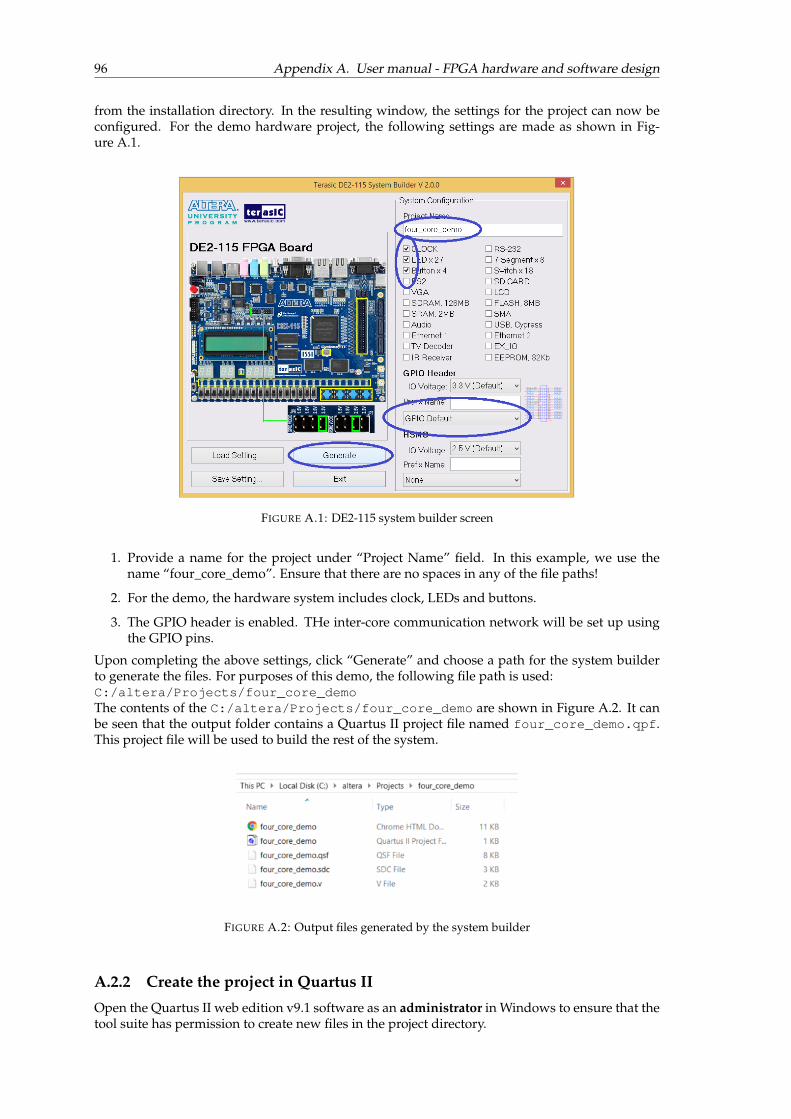
96 Appendix A. User manual - FPGA hardware and software design
from the installation directory. In the resulting window, the settings for the project can now beconfigured. For the demo hardware project, the following settings are made as shown in Fig-ure A.1.
FIGURE A.1: DE2-115 system builder screen
1. Provide a name for the project under “Project Name” field. In this example, we use thename “four_core_demo”. Ensure that there are no spaces in any of the file paths!
2. For the demo, the hardware system includes clock, LEDs and buttons.
3. The GPIO header is enabled. THe inter-core communication network will be set up usingthe GPIO pins.
Upon completing the above settings, click “Generate” and choose a path for the system builderto generate the files. For purposes of this demo, the following file path is used:C:/altera/Projects/four_core_demoThe contents of the C:/altera/Projects/four_core_demo are shown in Figure A.2. It canbe seen that the output folder contains a Quartus II project file named four_core_demo.qpf.This project file will be used to build the rest of the system.
FIGURE A.2: Output files generated by the system builder
A.2.2 Create the project in Quartus II
Open the Quartus II web edition v9.1 software as an administrator in Windows to ensure that thetool suite has permission to create new files in the project directory.

A.2. Creating the hardware design 97
In the “Welcome” page of the tool, click “Open Existing Project”.Alternatively click File→ Open Project . . .Navigate to the folder with output files from the system builder.In this demo: C:/altera/Projects/four_core_demo.Select the four_core_demo.qpf file to open it in the Quartus II tool. The steps are shown inFigure A.3.We now have to add the individual components to the system design using the SOPC builder
FIGURE A.3: Opening the project file in Quartus II
tool.To open the SOPC builder tool click Tools→ SOPC BuilderIn the opening screen of the SOPC builder, a prompt automatically appears for the creating a newsystem as shown in Figure A.4.For purposes of this demo, we create a new system with the name four_core_SOPC
FIGURE A.4: Create a new system in SOPC builder
A.2.3 Adding 4 Nios II cores
To add a Nios II processor to the system, from the System Contents menu on the left view theComponent library.

98 Appendix A. User manual - FPGA hardware and software design
In the Component library select Processors→ Nios II processor as shown in Figure A.5.A new window named “Nios II processor - cpu_0” appears. The wizard contains options for
FIGURE A.5: Add a Nios II processor to the design - step 1
choosing between three types of Nios II cores. For the purpose of this demo, we select the NiosII/f core as shown in Figure A.6Select “finish” to add the Nios II core to the system. Repeat the same steps three more times to
FIGURE A.6: Add a Nios II processor to the design - step 2
get a total of 4 Nios II cores in the system. The newly added cores are automatically named fromcpu_0 to cpu_3 as shown in the Figure A.7
FIGURE A.7: Add a Nios II processor to the design - step 3

A.2. Creating the hardware design 99
A.2.4 Adding internal memory to the system
As a next step, we add internal memory to the system for all the four cores in the system.In the Component library select Memories and Memory Controllers→On-chip→On-Chip Mem-ory (RAM or ROM) as shown in Figure A.8.
A new window named “On-Chip Memory (RAM or ROM) - onchip_memory2_0” opens with
FIGURE A.8: Adding internal memory to the design - step 1
configuration options for the on-chip memory.Select “RAM memory”Set the “Data Width” to 32We intend to allocate 48 KBytes of memory for each core in the system. Hence the “Total memorysize” for the system is 192 KBytes or 196608 Bytes.The steps for configuring the internal memory is shown in Figure A.9.
A.2.5 Adding a Mutex to the design
For enabling mutual exclusive access to shared data structures in the operating system kernel,hardware mutex is required in the system.To add a new mutex in the system (Figure A.10), on the Component library selectPeripherals→Multiprocessor Coordination→MutexSince we intend to use Erika Enterprise as the RTOS, it requires the mutex to be created with the
master CPU as the initial owner of the mutex. Considering that cpu_0 in our design is the masterCPU, we assign the value of the mutex as 0x01 and specify cpu_0 as the initial owner of the mutexas shown in Figure A.11.
A.2.6 Inter-core interrupt input lines
To enable inter-core communication, every core must have an incoming interrupt line. To add aninput interrupt the following actions are performed:Select Peripherals→Microcontroller Peripherals→ PIO (Parallel I/O)
A new window named “PIO (Parallel I/O) - pin_0” appears.In the Basic Setting tab: (Figure A.12a)Set “Width” to 1.Set “Direction” to Input ports only.In the Input Options tab: (Figure A.12b)Check “Synchronously capture”Set to “Raising edge”Check “Generate IRQ”

100 Appendix A. User manual - FPGA hardware and software design
FIGURE A.9: Adding internal memory to the design - step 2
FIGURE A.10: Adding a mutex to the design - step 1
Set to “Edge”Click “Finish”Repeat the steps 4 times to create 4 input lines. Rename the lines as “ipic_input_0” . . . “ipic_input_3”.(Figure A.13
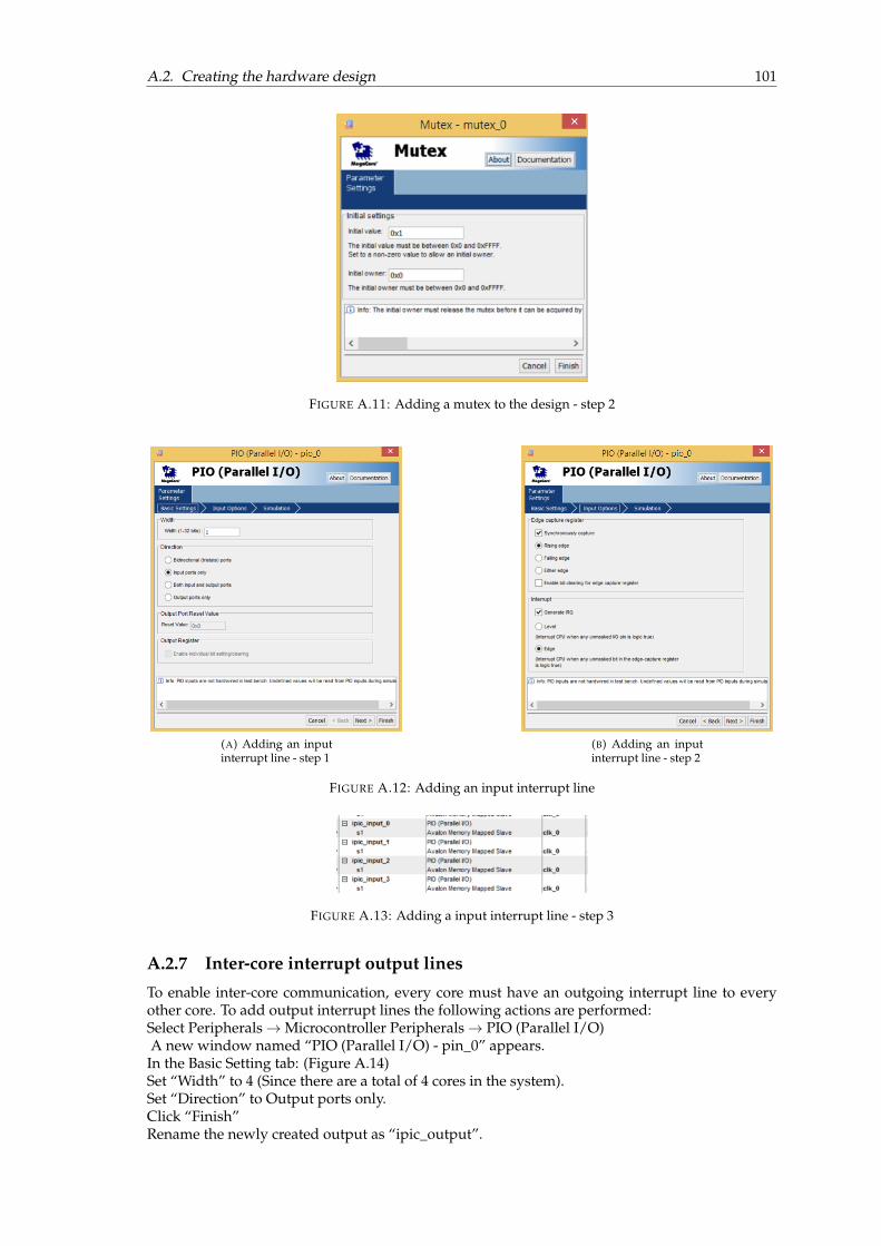
A.2. Creating the hardware design 101
FIGURE A.11: Adding a mutex to the design - step 2
(A) Adding an inputinterrupt line - step 1
(B) Adding an inputinterrupt line - step 2
FIGURE A.12: Adding an input interrupt line
FIGURE A.13: Adding a input interrupt line - step 3
A.2.7 Inter-core interrupt output lines
To enable inter-core communication, every core must have an outgoing interrupt line to everyother core. To add output interrupt lines the following actions are performed:Select Peripherals→Microcontroller Peripherals→ PIO (Parallel I/O)A new window named “PIO (Parallel I/O) - pin_0” appears.In the Basic Setting tab: (Figure A.14)Set “Width” to 4 (Since there are a total of 4 cores in the system).Set “Direction” to Output ports only.Click “Finish”Rename the newly created output as “ipic_output”.

102 Appendix A. User manual - FPGA hardware and software design
FIGURE A.14: Adding output interrupt lines - step 1
A.2.8 Adding a button input for each core
To add button inputs for each core, perform the following steps once for each button input:Select Peripherals→Microcontroller Peripherals→ PIO (Parallel I/O)In the Basic Setting tab:Set “Width” to 1.Set “Direction” to Input ports only.In the Input Options tab:Check “Synchronously capture”Set to “Raising edge”Check “Generate IRQ”Set to “Edge”Click “Finish”Repeat the steps 4 times to create 4 input buttons. Rename the buttons as “button_pio_0”
FIGURE A.15: Adding button inputs
. . . “button_pio_3”. (Figure A.15)
A.2.9 Adding 4 LEDs for each core in the system
To add four LEDs each to every core in the system, the following steps are performed:Select Peripherals→Microcontroller Peripherals→ PIO (Parallel I/O)A new window named “PIO (Parallel I/O) - pin_0” appears.In the Basic Setting tab: (Figure A.14)Set “Width” to 4 (Since we connect 4 LEDs to each core).Set “Direction” to Output ports only.Click “Finish”Repeat the above steps 4 times to create four such outputs. Rename the outputs as “led_pio_0”. . . “led_pio_3”.
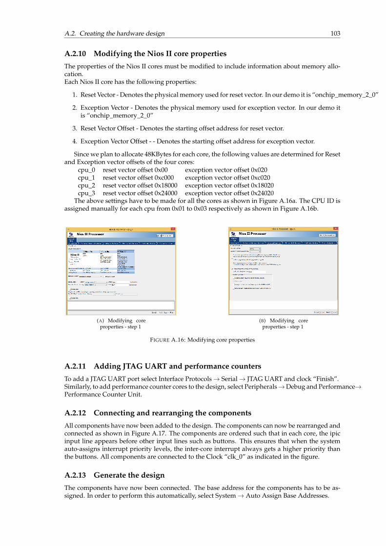
A.2. Creating the hardware design 103
A.2.10 Modifying the Nios II core properties
The properties of the Nios II cores must be modified to include information about memory allo-cation.Each Nios II core has the following properties:
1. Reset Vector - Denotes the physical memory used for reset vector. In our demo it is “onchip_memory_2_0”
2. Exception Vector - Denotes the physical memory used for exception vector. In our demo itis “onchip_memory_2_0”
3. Reset Vector Offset - Denotes the starting offset address for reset vector.
4. Exception Vector Offset - - Denotes the starting offset address for exception vector.
Since we plan to allocate 48KBytes for each core, the following values are determined for Resetand Exception vector offsets of the four cores:
cpu_0 reset vector offset 0x00 exception vector offset 0x020cpu_1 reset vector offset 0xc000 exception vector offset 0xc020cpu_2 reset vector offset 0x18000 exception vector offset 0x18020cpu_3 reset vector offset 0x24000 exception vector offset 0x24020
The above settings have to be made for all the cores as shown in Figure A.16a. The CPU ID isassigned manually for each cpu from 0x01 to 0x03 respectively as shown in Figure A.16b.
(A) Modifying coreproperties - step 1
(B) Modifying coreproperties - step 1
FIGURE A.16: Modifying core properties
A.2.11 Adding JTAG UART and performance counters
To add a JTAG UART port select Interface Protocols→ Serial→ JTAG UART and clock “Finish”.Similarly, to add performance counter cores to the design, select Peripherals→Debug and Performance→Performance Counter Unit.
A.2.12 Connecting and rearranging the components
All components have now been added to the design. The components can now be rearranged andconnected as shown in Figure A.17. The components are ordered such that in each core, the ipicinput line appears before other input lines such as buttons. This ensures that when the systemauto-assigns interrupt priority levels, the inter-core interrupt always gets a higher priority thanthe buttons. All components are connected to the Clock “clk_0” as indicated in the figure.
A.2.13 Generate the design
The components have now been connected. The base address for the components has to be as-signed. In order to perform this automatically, select System→ Auto Assign Base Addresses.

104 Appendix A. User manual - FPGA hardware and software design
FIGURE A.17: Rearrange and connect components
Similarly to auto-assign the IRQ priority levels, select System→ Auto Assign IRQs.Ensure that there are no errors in the information window at the bottom of the page.Save the design and click “Generate” to start the system generation.Upon successful completion of the system generation, the message shown in Figure A.18 is dis-played in the window.
FIGURE A.18: Successful completion of system generation
A.3 Synthesis of the design
After the completion of system generation, exit the SOPC builder tool and return to the QuartusII main window.

A.3. Synthesis of the design 105
A.3.1 Pin assignment
We now have to assign the pins for components such as buttons, LEDs and inter-core interruptlines on the FPGA board.In the Project Navigator pane, double-click the top entity “four_core_demo” as shown in Fig-ure A.19.
FIGURE A.19: Top entity in project navigator
This opens the four_core_demo.v file which is the main verilog file defining the connec-tions in the system. We now have to add the pin assignments to end of the file flagged by thecomment “Structural coding”.The component information is available in the output folder of the SOPC builder.Click File→ Open→ four_core_SOPC.vThis opens the four_core_SOPC.v file which contains all the module informations of the gen-erated system design. We now have to find the main module in the file. The main module isnamed “four_core_SOPC”. Search for the module in the file and copy the entire module as shownin Figure A.20.
FIGURE A.20: Copy the contents of the module from four_core_SOPC.v file
Paste the copied contents under the “Structural coding” part of four_core_demo.v file be-fore the “endmodule” keyword.Modify the pasted contents as shown in Listing A.1.The physical pin details for the board can be found in [48].
1 //=======================================================2 //Structural coding3 //=======================================================4
5 four_core_SOPC u0(6 //1)globalsignals:7 .clk_0(CLOCK_50),

106 Appendix A. User manual - FPGA hardware and software design
8 .reset_n(1’b1),9
10 //the_button_pio_011 .in_port_to_the_button_pio_0(KEY[0]),12
13 //the_button_pio_114 .in_port_to_the_button_pio_1(KEY[1]),15
16 //the_button_pio_217 .in_port_to_the_button_pio_2(KEY[2]),18
19 //the_button_pio_320 .in_port_to_the_button_pio_3(KEY[3]),21
22 //the_ipic_input_023 .in_port_to_the_ipic_input_0(GPIO[4]),24
25 //the_ipic_input_126 .in_port_to_the_ipic_input_1(GPIO[5]),27
28 //the_ipic_input_229 .in_port_to_the_ipic_input_2(GPIO[6]),30
31 //the_ipic_input_332 .in_port_to_the_ipic_input_3(GPIO[7]),33
34 //the_ipic_output35 .out_port_from_the_ipic_output({GPIO[3],GPIO[2],GPIO[1],GPIO[0]}),36
37 //the_led_pio_038 .out_port_from_the_led_pio_0({LEDG[3],LEDG[2],LEDG[1],LEDG[0]}),39
40 //the_led_pio_141 .out_port_from_the_led_pio_1({LEDG[7],LEDG[6],LEDG[5],LEDG[4]}),42
43 //the_led_pio_244 .out_port_from_the_led_pio_2({LEDR[3],LEDR[2],LEDR[1],LEDR[0]}),45
46 //the_led_pio_347 .out_port_from_the_led_pio_3({LEDR[7],LEDR[6],LEDR[5],LEDR[4]}),48 )49 ;
LISTING A.1: Contents specifying pin assignments that must be added to thefour_core_demo.v file
A.3.2 Analysis and synthesis
To compile and synthesize the hardware, click on the “Compile Design” option in the Tasks paneon the left (Figure A.21)
FIGURE A.21: Analysis and synthesis
To program the hardware, connect the DE2-115 board via USB and click Tools→ Programmer.In the programmer window, click “Start” to program the device.
A.4. Software creation 107
A.4 Software creation
The software components required are listed below:
EMF 2.0.3 http://erika.tuxfamily.org/wiki/index.php?title=Altera_Nios_II
GEF SDK 3.0.1 http://erika.tuxfamily.org/wiki/index.php?title=Altera_Nios_II
Native Erika 090504_evidence_ee.zip http://erika.tuxfamily.org/wiki/index.php?title=Altera_Nios_II
FSLM Erika evidence_ee https://github.com/srimuthu/Erika-FSLM
rtd_gpl_nios2__142___20090511_1832.zip http://erika.tuxfamily.org/wiki/index.php?title=Altera_Nios_II
Steps for the creation of software system are identical to the ones presented in Appendix B.3of [4].


109
Appendix B
Flex-Tool guide
Flex-Tool is a utility tool developed for the Erika implementation of FSLM to accomplish thefollowing tasks semi-autonomously:
1. Determine priorities from OIL file
2. Receive user input for spin-lock priorities
3. Add spin-lock priorities to Erika application
4. Modify stack to create dual shared stack
B.1 Tool usage
How to download
The Flex-Tool can be downloaded from github by cloning the following repository:https://github.com/srimuthu/Erika-FSLM.git
Path to Flex-Tool in the repository: Erika-FSLM/flex_prio_tool/FlexTool.py
Flex-Tool detailsFile name FlexTool.pyRequires Python version Python 3Package dependencies prettytable
(for displaying output on the consolein table format)
Usage instructions
This guide presents a step-by-step guide for using the Flex-Tool.
1. Place the file FlexTool.py in the same directory that contains the conf.oil file.
2. Flex-Tool assumes that the user has not modified the following default file names:
• The OIL file : conf.oil
• The CPU application source files : cpuX_main.cwhere X is replaced by the cpu ID. For instance, cpu0_main.c
3. For the Flex-Tool to work as expected, the following convention must be followed in theOIL file while mentioning the STACK attribute of the TASK object. Please ensure that thekeyword STACK and the corresponding terminator (;) appear on the same line, i.e., withouta new-line character (“\ n”) in-between. The following snippet shows the correct and wrongmethods:

110 Appendix B. Flex-Tool guide
FIGURE B.1: Flex-Tool example summary of application and prompt for user input
1 // Correct convention2 STACK = PRIVATE{ SYS_SIZE = 0x100; };3
4 //Please avoid the following method5 STACK = PRIVATE{6 SYS_SIZE = 0x100;7 };
LISTING B.1: Convention for mentioning the TASK STACK attribute in OILfile

B.1. Tool usage 111
FIGURE B.2: Refresh and build the project
FIGURE B.3: Running the program on the hardware
4. The tool involves setting of spin-lock priorities in the application depending on the user-input. In order to do so, the CPU application source files must contain the following globalvariables:
1 const int EE_th_spin_prio[] = {};2 const int GlobalTaskID[] = {};
LISTING B.2: CPU application file variables
Kindly note that it is sufficient for the cpuX_main.c to just contain these variables. Flex-Tool will automatically find and modify the values of the above variables during run-time.
5. Run the Flex-Tool by using the following command:
1 $ <path to source dir> python FlexTool.py
6. The Flex-Tool parses the OIL file and determines the spin-lock priority ranges. The com-plete summary of the application are presented on the console for the user to verify thecorrectness as shown in Figure B.1. It then prompts the user to input a spin-lock priority foreach core.
112 Appendix B. Flex-Tool guide
7. The “Derived Priority” table displayed on the console provides information about the priority-levels on each core. The user can use the information to input the spin-lock priority for eachcore.
8. Upon completing the user input, Flex-Tool computes the spin-priorities, modifies the valuesof the variables listed in Listing B.2 for each cpu, computes the stack allocation for the ap-plication and accordingly edits the OIL file. The user is then prompted to refresh the projectin eclipse and Clean and Build Erika.
9. On Nios II IDE, refresh the project (optionally clean) and then build the project as shown inFigure B.2.
10. When the build is complete, preyy “y” in the python console to resume Flex-Tool. TheFlex-Tool will now edit the eecfg.c files of the CPUs to modify the stack data.
11. The user is prompted upon completion of the updates.
12. Finally, use the “Run” option in the Nios II IDE to generate the .elf file and run the pro-gram on the hardware as shown in Figure B.3
WARNING ! DO NOT RE-BUILD ERIKA AFTER THE LAST STEP AS THIS WILL CAUSE RT-DRUID TO OVERWRITE THE CHANGES MADE TO EECFG.C FILES BY THE FLEX-TOOL! JUSTRUN THE CONFIGURATION AS THIS INITIALIZES ONLY THE MAKEFILES NECESSARY TO GEN-ERATE EXECUTABLE FILE WITHOUT INITIALIZING RT-DRUID.

class FlexTool.FlexTool(oilPath)FlexTool Class - Utility tool for FSLM implementation in Erika Enterprise
Comments []
1. Determine priorities from OIL file
2. Receive user input for spin-lock priorities
3. Add spin-lock priorities to Erika application
4. Modify configuration files to create dual shared stack
_FlexTool__calculateSpinPriorities()Convert user input spin-priorities to Erika format (2^i)
_FlexTool__calculateStackAllocation()Group tasks on a core to 2 stacks based on spin-lock priority
_FlexTool__createResourceList()Create Resouce list data structure from OIL file
Comments: __resourceInfo dict consists of
{resID (int) : resource name (str)}
_FlexTool__createTaskData(task_counter)Create Task information data structure from OIL file
Comments: The __taskInfo dict consists of:
taskID (int) : [ [0] taskName (str),
[1] cpuID (int),
[2] cpuName (str),
[3] taskPriority (int),
[4] resourceBool (bool),
[5] resources (list) = [resourceName (str)] ]
_FlexTool__displayParams()Output task, resource and CPU info to the console
_FlexTool__editSystemTos(block_data, cpu)Edit “EE_nios2_system_tos” variable in “eecfg.c”
Arguments: block_data - Part of file buffer from eecfg.c containing EE_nios2_system_tos,
cpu - CPU ID (cpu which the eecfg.c file belongs to)
Returns: Success or Failed (bool),
Edited file buffer of eecfg.c containing EE_nios2_system_tos
_FlexTool__editThreadTos(block_data, cpu)Edit “EE_hal_thread_tos” variable in “eecfg.c”
Arguments: block_data - Part of file buffer from eecfg.c containing EE_hal_thread_tos,
cpu - CPU ID (cpu which the eecfg.c file belongs to)
Returns: Success or Failed (bool),
Edited file buffer of eecfg.c containing EE_hal_thread_tos
113
B.2 Auto generated documentation

_FlexTool__findBraceBlock(data, item)” Identify the brace enclosed block containing a given string
Arguments: data - file buffer ,
item - item to be found (str)
Returns: Index of brace block start
Index of brace block end
Data enclosed between in the block containing the (item)
_FlexTool__findGlobalResources()Identify global resources (classify local and global resources)
_FlexTool__parseCpuInfo()Extract CPU information from OIL file
Called by : parseOilFile()
Comments [] Iterate through the OIL file and save CPU info to __cpuInfo dict __cpuInfo: { cpuID (int) :cpuName (str) }
_FlexTool__parseTaskInfo()Extract task information from OIL file
_FlexTool__reducePriorities()Transform priority levels within a core to consecutive values starting with 0 (lowest)
_FlexTool__spliceTextToFileBuffer(file_buffer, block_data, start_index, end_index)Inserts given text into a file at specified location
Arguments: file_buffer - Full file buffer
block_data - Data to be inserted
start_index - Start position to insert
end_index - End position
Returns: splicedList - Full file buffer with block_data inserted
calculatePriorities()Calculate CP, CP hat and HP priorities
Calls [] __findGlobalResources()
__reducePriorities()
__displayParams()
Called by [] main() using FlexTool object
Comments []
1. Identify global variables
2. Transform priority levels within a core to consecutive values starting with 0 (lowest)
3. Use available data to find CP, CP hat and HP for every core
getUserInput()Get input from the user
Calls [] __calculateSpinPriorities()
__calculateStackAllocation()
114

Called by [] main() using FlexTool object
Comments []
1. Prompt user for spin-lock priority per core
2. Convert priorities to HEX
3. Determine stack allocation of tasks into dual stacks on each core
initializeFlexSpinToolVars()Initialize the flexible spin-lock priority tool related variables
Called by [] main() using FlexTool object
Comments [] Uses variables __cpuInfo, __taskInfo, __resourceInfo to construct mapping between tasks,cores and resources
parseOilFile()Parse and extract information from OIL file
Returns [] self.__cpuInfo, self.__taskInfo, self.__resourceInfo
Calls [] __parseCpuInfo(), __parseTaskInfo(), __createResourceList()
Called by [] main() using FlexTool object
promptUser()Prompts user to rebuild Erika.
Comments: This prompt is followed by the editing of eecfg.c files for dual stack implementation
returnFlexSpinInfo()Return __spinPrio, __tasks2stack, __cpuInfo, __tasks2cores
updateCfgFiles()Function to update Erika configuration files “eecfg.c” on all cores to include stack information
Called by [] main() using FlexTool object
Comments [] For all cores, modifies the “eecfg.c” to have only 2 shared stacks per core as per dual stackconfiguration
updateOilFile()Modifies task stack info in OIL file to accommodate dual stack
Called by [] main() using FlexTool object
Comments [] Update “conf.OIL” file with task STACK attribute
1. SHARED for tasks with priorities upto spin-lock priority
2. PRIVATE for other tasks (later modified to shared after code generation by updateCfgFiles() )
————–!!!WARNING!!!————–
Only works for single line STACK attribute. Please specify the STACK attribute in a single line in theOIL file i.e keyword “STACK” and terminator “;” must be on the same line.
updateSourceFiles()Update the application source files based on user input for spin-lock priority
Called by [] main() using FlexTool object
Comments [] Update “cpuXX_main.c” files for all cores
1. update EE_th_spin_prio
115

2. update GlobalTaskID
Throws error if the above variables are not found in the file
Also throws error if the file “cpuXX_main.c” is not found (XX = cpu ID (integer))
116
117
Bibliography
[1] “AUTOSAR release 4.3”, 2016. [Online]. Available: http://www.autosar.org.
[2] S. Afshar, M. Behnam, R. Bril, and T. Nolte, “Flexible spin-lock model for resource sharingin multiprocessor real-time systems”, in Proc. 9th IEEE International Symposium on IndustrialEmbedded Systems (SIES), Jun. 2014, pp. 41–51. DOI: 10.1109/SIES.2014.6871185.
[3] S. Afshar, M. P. W. Verwielen, P. Gai, M. Behnam, and R. J. Bril, “An implementation of theflexible spin-lock model in Erika Enterprise on a multi-core platform”, in Proc. 12th AnnualWorkshop on Operating Systems Platforms for Embedded Real-Time Applications (OSPERT), Jul.2016, pp. 55–60.
[4] M. P. Verwielen, “Performance of resource access protocols”, Eindhoven University of Tech-nology (TU/e), Master’s thesis, Jun. 2016. [Online]. Available: http://repository.tue.nl/854620.
[5] P. Gai, G. Lipari, and M. Di Natale, “Minimizing memory utilization of real-time task sets insingle and multi-processor systems-on-a-chip”, in Proc. 22nd IEEE Real-Time Systems Sympo-sium (RTSS), Dec. 2001, pp. 73–83. DOI: 10.1109/REAL.2001.990598.
[6] R. Rajkumar, L. Sha, and J. Lehoczky, “Real-time synchronization protocols for multipro-cessors”, in Proc. 19th IEEE International Real-Time Systems Symposium (RTSS), Dec. 1988,pp. 259–269. DOI: 10.1109/REAL.1988.51121.
[7] S. Afshar, M. Behnam, R. Bril, and T. Nolte, “Per Processor Spin-Lock Priority for Parti-tioned Multiprocessor Real-Time Systems”, pp. 1–26, Sep. 2016, unpublished paper.
[8] Evidence S.r.l. (Jun. 2016). Erika Enterprise OS http://erika.tuxfamily.org/drupal/, [On-line]. Available: http://erika.tuxfamily.org/drupal/.
[9] Altera Corporation. (2016). Altera Nios II processor, [Online]. Available: https://www.altera.com/products/processors/overview.html (visited on 11/17/2016).
[10] S. M. N. Balasubramanian, S. Afshar, M. Behnam, P. Gai, and R. J. Bril, “Incorporating im-plementation overheads in the analysis for the Flexible Spin-Lock Model”, Submitted to the43rd Annual Conference of the IEEE Industrial Electronics Society (IECON), Nov. 2017.
[11] ——, “A dual shared stack for FSLM in Erika Enterprise”, Accepted for the 23rd IEEE In-ternational Conference on Embedded and Real-Time Computing Systems and ApplicationsWork-in-Progress (WiP) session (RTCSA), Aug. 2017.
[12] S. Afshar, Lock-based resource sharing in real-time multiprocessor platforms, Please contact theauthors if you would like to have a higher quality electronic version., Nov. 2014. [Online].Available: http://www.es.mdh.se/publications/3837-.
[13] M. Shaw, “The coming-of-age of software architecture research”, in Proc. 23rd InternationalConference on Software Engineering, ser. ICSE ’01, Toronto, Ontario, Canada: IEEE ComputerSociety, 2001, pp. 656–, ISBN: 0-7695-1050-7. [Online]. Available: http://dl.acm.org/citation.cfm?id=381473.381549.
[14] L. Sha, R. Rajkumar, and J. Lehoczky, “Priority inheritance protocols: An approach to real-time synchronization”, IEEE Transactions on Computers, vol. 39, no. 9, pp. 1175–1185, Sep.1990, ISSN: 0018-9340. DOI: 10.1109/12.57058.
[15] T. Baker, “Stack-based scheduling of real-time processes”, Journal of Real-Time Systems, vol.3, no. 1, pp. 67–99, Mar. 1991.
[16] G. C. Buttazzo, Hard real-time computing systems: Predictable scheduling algorithms and appli-cations (real-time systems series). Santa Clara, CA, USA: Springer-Verlag TELOS, Oct. 2004,ISBN: 0387231374.

118 BIBLIOGRAPHY
[17] D. Faggioli, G. Lipari, and T. Cucinotta, “The multiprocessor bandwidth inheritance proto-col”, in Proc. 22nd Euromicro Conference on Real-Time Systems, ser. ECRTS ’10, IEEE ComputerSociety, 2010, pp. 90–99.
[18] A. Burns and A. Wellings, “A schedulability compatible multiprocessor resource sharingprotocol – mrsp”, in Proc. 25th Euromicro Conference on Real-Time Systems, 2013. DOI: 10.1109/ecrts.2013.37.
[19] R. Rajkumar, Synchronization in real-time systems: A priority inheritance approach. Kluwer Aca-demic Publishers, 1991, ISBN: 0792392116.
[20] A. Block, H. Leontyev, B. Brandenburg, and J. Anderson, “A flexible real-time locking pro-tocol for multiprocessors”, in Proc. 13th IEEE International Conference on Embedded and Real-Time Computing Systems and Applications (RTCSA), Aug. 2007, pp. 47–56. DOI: 10.1109/RTCSA.2007.8.
[21] M. Saksena and Y. Wang, “Scalable real-time system design using preemption thresholds”,in Proc. 21st IEEE Conference on Real-time Systems Symposium, ser. RTSS’10, Orlando, Florida:IEEE Computer Society, 2000, pp. 25–34, ISBN: 0-7695-0900-2. [Online]. Available: http://dl.acm.org/citation.cfm?id=1890629.1890633.
[22] P. Gai, M. Di Natale, G. Lipari, A. Ferrari, C. Gabellini, and P. Marceca, “A comparisonof MPCP and MSRP when sharing resources in the Janus multiple-processor on a chipplatform”, in Proc. 9th IEEE Real-Time and Embedded Technology and Applications Symposium(RTAS), May 2003, pp. 189–198. DOI: 10.1109/RTTAS.2003.1203051.
[23] B. Brandenburg and J. Anderson, “An implementation of the PCP, SRP, D-PCP, M-PCP,and FMLP real-time synchronization protocols in LITMUS”, in Proc. 14th IEEE Intl. Conf. onEmbedded and Real-Time Comp. Systems and Applications (RTCSA), Aug. 2008, pp. 185–194.
[24] J. M. Calandrino, H. Leontyev, A. Block, U. C. Devi, and J. H. Anderson, “LITMUS: Atestbed for empirically comparing real-time multiprocessor schedulers”, in Proc. 27th IEEEInternational Real-Time Systems Symposium (RTSS), Dec. 2006, pp. 111–126. DOI: 10.1109/RTSS.2006.27.
[25] B. B. Brandenburg and J. H. Anderson, “A comparison of the M-PCP, D-PCP, and FMLP onLITMUS”, in Proc. 12th International Conference On Principles of Distributed Systems (OPODIS),Dec. 2008, pp. 105–124, ISBN: 978-3-540-92221-6. DOI: 10.1007/978-3-540-92221-6_9.[Online]. Available: http://dx.doi.org/10.1007/978-3-540-92221-6_9.
[26] B. B. Brandenburg, J. M. Calandrino, A. Block, H. Leontyev, and J. H. Anderson, “Real-time synchronization on multiprocessors: To block or not to block, to suspend or spin?”, inProc. 14th Real-Time and Embedded Technology and Applications Symposium (RTAS), May 2008,pp. 342–353. DOI: 10.1109/RTAS.2008.27.
[27] Evidence S.r.l., “Erika Enterprise Manual for the Altera Nios II target - the multicore RTOSon FPGAs (version 1.2.3)”, Evidence S.r.l., Pisa, Italy, Tech. Rep. http://download.tuxfamily.org/erika/webdownload/manuals_pdf/arch_nios2_1_2_3.pdf,Dec. 2012. (visited on 05/20/2017).
[28] M. Klein, T. Ralya, B. Pollak, R. Obenza, and M. Harbour, A practitioner’s handbook for real-time analysis. Norwell, MA, USA: Kluwer Academic Publishers, Oct. 1993, ISBN: 978-1-4615-2796-1.
[29] F. M. David, J. C. Carlyle, and R. H. Campbell, “Context switch overheads for Linux onARM platforms”, in Proc. 2007 Workshop on Experimental Computer Science, ser. ExpCS ’07,San Diego, California: ACM, 2007, ISBN: 978-1-59593-751-3. DOI: 10.1145/1281700.1281703. [Online]. Available: http://doi.acm.org/10.1145/1281700.1281703.
[30] C. M. Bailey, A. Burns, A. J. Wellings, and C. Forsyth, A performance analysis of a hard real-timesystem, 1994.
[31] A. Burns, K. Tindell, and A. Wellings, “Fixed priority scheduling with deadlines prior tocompletion”, In Proc. 6th Euromicro Workshop on Real-Time Systems, DOI: 10.1109/emwrts.1994.336852.

BIBLIOGRAPHY 119
[32] N. C. Audsley, I. J. Bate, and A. Burns, “Putting fixed priority scheduling theory into engi-neering practice for safety critical applications”, in Proc. 2nd IEEE Real-Time Technology andApplications Symposium, ser. RTAS ’96, Washington, DC, USA: IEEE Computer Society, 1996,ISBN: 0-8186-7448-2. [Online]. Available: http://dl.acm.org/citation.cfm?id=524958.828347.
[33] R. Davis, K. Tindell, and A. Burns, “Scheduling slack time in fixed priority pre-emptivesystems”, In Proc. 14th IEEE Real-Time Systems Symposium, 1993. DOI: 10.1109/real.1993.393496.
[34] Audsley, Davis, and Burns, “Mechanisms for enhancing the flexibility and utility of hardreal-time systems”, In Proc. 15th IEEE Real-Time Systems Symposium, 1994. DOI: 10.1109/real.1994.342734.
[35] M. Holenderski, “Real-time system overheads: A literature overview”, Eindhoven Univer-sity of Technology, Technical Report, Oct. 2008.
[36] Altera Corporation, “Creating Multiprocessor Nios II Systems Tutorial”, Solutions, Jun. 2010.
[37] Evidence S.r.l., “RT-Druid reference manual - A tool for the design of embedded real-time systems (version: 1.5.0)”, Evidence S.r.l., Pisa, Italy, Tech. Rep. http://download.tuxfamily.org/erika/webdownload/manuals_pdf/rtdruid_refman_1_5.0.pdf, Dec. 2012. (visited on 05/20/2017).
[38] The Eclipse Foundation, “Eclipse”, Tech. Rep. http://www.eclipse.org/, Apr. 2017.(visited on 04/17/2017).
[39] P. Gai, E. Bini, G. Lipari, M. D. Natale, and L. Abeni, “Architecture for a portable opensource real time kernel environment”, in Proc. 2nd Real-Time Linux Workshop and Hand’s onReal-Time Linux Tutorial, 2000.
[40] G. Graunke and S. Thakkar, “Synchronization algorithms for shared-memory multiproces-sors”, IEEE Computer, vol. 23, no. 6, pp. 60–69, Jun. 1990, ISSN: 0018-9162. DOI: 10.1109/2.55501.
[41] Altera Corporation, “Quartus II 8.1 handbook, Volume 5: Embedded peripherals, Chapter29: Performance counter core”, Tech. Rep. https://www.altera.com/en_US/pdfs/literature/hb/qts/archives/quartusii_handbook_8.1.pdf, Nov. 2008, pp. 29-1–29-11. (visited on 07/19/2017).
[42] OSEK/VDX Consortium, “OIL: OSEK Implementation Language”, Tech. Rep., Jul. 2004.
[43] Evidence S.r.l., “Erika Enterprise Manual - Real-time made easy (version: 1.4.5)”, EvidenceS.r.l., Pisa, Italy, Tech. Rep. http://download.tuxfamily.org/erika/webdownload/manuals_pdf/ee_refman_1_4_5.pdf, Dec. 2012.
[44] Y. Wang and M. Saksena, “Scheduling fixed-priority tasks with preemption threshold”, inProc. 6th International IEEE Conference on Real-Time Computing Systems and Applications(RTCSA),ser. RTCSA ’99, Hong Kong, China: IEEE, 1999, ISBN: 0-7695-0306-3. [Online]. Available:http://ieeexplore.ieee.org/stamp/stamp.jsp?tp=&arnumber=811269.
[45] Altera Corporation, “Profiling Nios II systems”, Tech. Rep. https://www.altera.com/literature/an/an391.pdf, Feb. 2006. (visited on 07/19/2017).
[46] D. A. Patterson, J. L. Hennessy, P. Alexander, J. D. Bakos, J. Bruguera, J. Chang, M. Far-rens, D. Kaeli, N. Kaiyan, D. Kirk, J. R. Larus, J. Leverich, K. Lim, J. Nickolls, J. Oliver,M. Prvulovic, and P. Ranganathan, Computer Organazation and Design. 2014, p. 792, ISBN:978-0-12-407726-3.
[47] Altera Corporation, “Instruction set reference”, Tech. Rep. https://www.altera.com/en_US/pdfs/literature/hb/nios2/n2cpu_nii51017.pdf, Apr. 2015. (visited on07/19/2017).
[48] ——, (2016). DE2-115 user manual, [Online]. Available: https://www.terasic.com.tw/cgi-bin/page/archive.pl?Language=English&CategoryNo=139&No=502&PartNo=4 (visited on 11/17/2016).