rb50/60 radar control box - electronica marina · general descriptions 1-1 chapter 1 general...
TRANSCRIPT

INSTALLATION MANUAL
RB50/60 Radar ctr box w/antennas
20222428 / B English

General descriptions Contents
Chapter 1
General Descriptions
Contents
Page No.
1.1 Inspections of the delivered goods .............................. 1-1 1.2 Checking the Power Supply Voltage............................ 1-4 1.3 Fuse Replacement....................................................... 1-4

General Descriptions 1-1
Chapter 1 General Descriptions
This chapter describes the procedures of the installation for the RB50/60 Radar control box and antenna in your ship and necessary precautions to be observed. The following diagram explains the order of the installations of this system.
1.1 Inspections of the delivered goods Unpack your package and check if all of the following items are included in good order.
4 kW Radome
Component Unit Sub-unit Type name
Antenna (Radome type) RB715A (4 kW)
Transceiver None
Radar Sensor Control Box None RB50
Inspections of the delivered goods
Checking the power supply voltage
Determining the place of installation
Installing the Control Box
Connecting the cables

1-2 General Descriptions
4 kW Open scanner
Component Unit Sub-unit Type name
Antenna RB716A (4 kW)
Transceiver None
Aerial, 3-foot RW701A-03
Aerial, 4-foot RW701A-04
Radar Control Box None RB50
6 kW Open scanner
Component Unit Sub-unit Type name
Antenna RB717A (6 kW)
Transceiver None
Aerial, 4-foot RW701A-04
Aerial, 6-foot RW701A-06
Radar Control Box None RB60
12 kW Open scanner
Component Unit Sub-unit Type name
Antenna RB718A (12 kW)
Transceiver None
Aerial, 4-foot RW701A-04
Aerial, 6-foot RW701A-06
Radar Control Box None RB60
General Descriptions 1-3
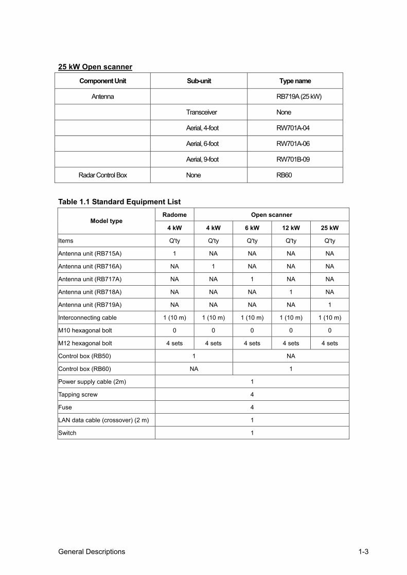
25 kW Open scanner
Component Unit Sub-unit Type name
Antenna RB719A (25 kW)
Transceiver None
Aerial, 4-foot RW701A-04
Aerial, 6-foot RW701A-06
Aerial, 9-foot RW701B-09
Radar Control Box None RB60
Table 1.1 Standard Equipment List
Radome Open scanner Model type
4 kW 4 kW 6 kW 12 kW 25 kW
Items Q'ty Q'ty Q'ty Q'ty Q'ty
Antenna unit (RB715A) 1 NA NA NA NA
Antenna unit (RB716A) NA 1 NA NA NA
Antenna unit (RB717A) NA NA 1 NA NA
Antenna unit (RB718A) NA NA NA 1 NA
Antenna unit (RB719A) NA NA NA NA 1
Interconnecting cable 1 (10 m) 1 (10 m) 1 (10 m) 1 (10 m) 1 (10 m)
M10 hexagonal bolt 0 0 0 0 0
M12 hexagonal bolt 4 sets 4 sets 4 sets 4 sets 4 sets
Control box (RB50) 1 NA
Control box (RB60) NA 1
Power supply cable (2m) 1
Tapping screw 4
Fuse 4
LAN data cable (crossover) (2 m) 1
Switch 1

1-4 General Descriptions
Table 1.2 Optional cable list Part No. Type Description
153-3001-002 4 kW radome RB715A 15 m radar cable with connectors (4 kW radome)
153-3001-003 Open scanner 15 m radar cable with connectors (open scanner)
153-3001-005 4 kW radome RB715A 20 m radar cable with connectors (4 kW radome)
153-3001-006 Open scanners 20 m radar cable with connectors (open scanner)
153-3001-007 4 kW radome and open scanners
100 m radar cable(all type scanners) w/o connectors
153-3002-317 30 m Universal radar cable with connectors kit
700-2100-006 4 kW radome and open scanners
Universal connector kit for all type scanners
1.2 Checking the Power Supply Voltage To allow proper operation of the radar, the ship’s power supply capacity must satisfy the requirements detailed in Table 1.3. Keep the battery properly charged anytime to prevent the mains voltage from discharging.
Table 1.3 Power Supply Requirements Supply voltage used Maximum current drain Allowable voltage range
12 VDC 5 A (4 kW) 7 A (6 kW) 8 A (12 kW)
10.2 to 41.6 V
2.5 A (4 kW Radome) 3 A (4 kW Open scanner) 3.5 A (6 kW) 4 A (12 kW)
10.2 to 41.6 V
24 VDC
5.4 A (25 kW) 18.6 to 41.6 V
CAUTION: AC power supply cannot be used
1.3 Fuse Replacement Properly rated fuses must be used for a safe and proper operation of the radar. Refer to the following tables for correct ratings of the fuses used in the respective models.
Table 1.4 Table of Supply Voltage and Fuse for 4 kW Radome Supply voltage used Main Fuse Motor Fuse
12 V DC 10 A/250 V or 125 V *(6.3 Ø x 32 mm)
T3.15 A/250 V or 125 V *(5Ø x 20 mm)
24 V DC 10 A/250 V or 125 V (6.3 Ø x 32 mm)
T3.15 A/250 V or 125 V (5Ø x 20 mm)
Table 1.5 Table of Supply Voltage and Fuse for 4kW Open scanner Supply voltage used Main Fuse Motor Fuse
12 V DC 10 A/250 V or 125 V (6.3Ø x 32 mm)
5 A/250 V or 125 V (5Ø x 20 mm)
24 V DC 10 A/250 V or 125 V * (6.3 Ø x 32 mm)
T3.15 A/250 V or 125 V *(5Ø x 20 mm)
Note: Fuses marked with * are in the set as standard.
Note: Fuses marked with * fuses are in the set as standard.

General Descriptions 1-5
Table 1.6 Table of Supply Voltage and Fuse for 6 kW Open scanner Supply voltage used Main Fuse Motor Fuse
12 VDC 10 A/250 V or 125V (6.3Ø x 32 mm) 5 A/250 V or 125 V (5Ø x 20 mm)
24 VDC 10 A/250 V or 125 V * (6.3 Ø x 32 mm) T3.15 A/250 V or 125 V *(5Ø x 20 mm)
Table 1.7 Table of Supply Voltage and Fuse for 12 kW Open scanner Supply voltage used Main Fuse Motor Fuse
12 VDC 10 A/250 V or 125 V (6.3Ø x 32 mm) 5 A/250 V or 125 V (5Ø x 20 mm)
24 VDC 10 A/250 V or 125 V * (6.3 Ø x 32 mm) T3.15 A/250 V or 125 V *(5Ø x 20 mm)
Table 1.8 Table of Supply Voltage and Fuse for 25 kW Open scanner
Supply voltage used Main Fuse Motor Fuse
24 VDC 10 A/250 V or 125 V * (6.3 Ø x 32 mm) 5 A/250 V or 125 V (5Ø x 20 mm)
T3.15 A/250 V or 125 V *(5Ø x 20 mm)
Note: Fuses marked with* are in the set as standard.
Note: Fuses marked with * are in the set as standard.
Note: Fuses marked with * are in the set as standard.
Installation Contents
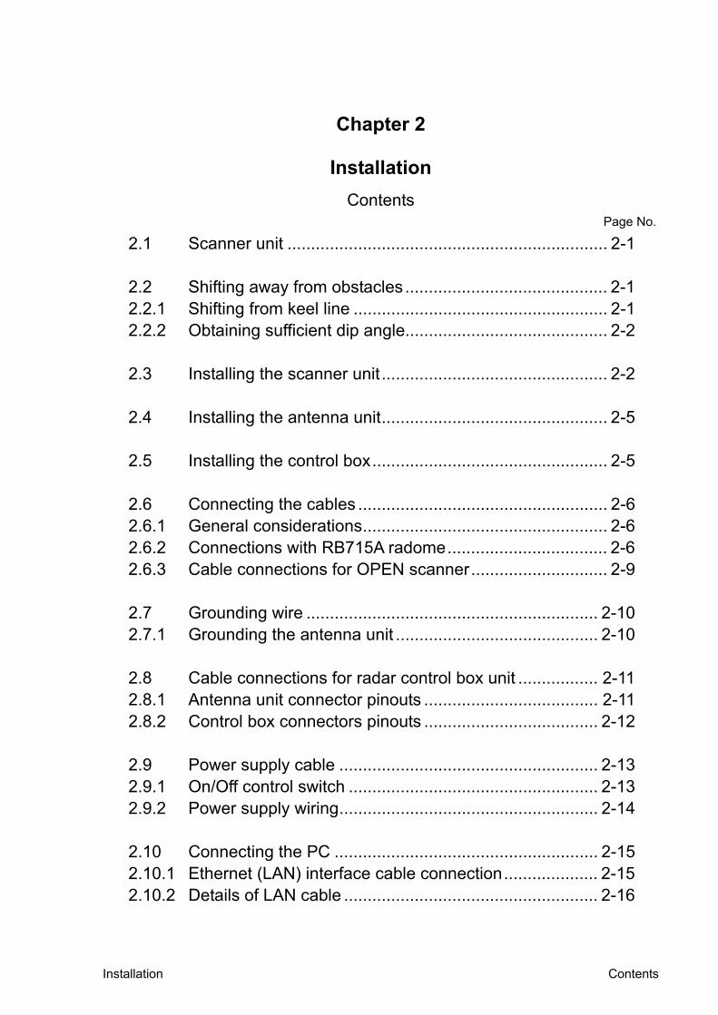
Chapter 2
Installation
Contents Page No.
2.1 Scanner unit .................................................................... 2-1
2.2 Shifting away from obstacles ........................................... 2-1 2.2.1 Shifting from keel line ...................................................... 2-1 2.2.2 Obtaining sufficient dip angle........................................... 2-2
2.3 Installing the scanner unit ................................................ 2-2 2.4 Installing the antenna unit................................................ 2-5
2.5 Installing the control box.................................................. 2-5 2.6 Connecting the cables ..................................................... 2-6 2.6.1 General considerations.................................................... 2-6 2.6.2 Connections with RB715A radome.................................. 2-6 2.6.3 Cable connections for OPEN scanner............................. 2-9 2.7 Grounding wire .............................................................. 2-10 2.7.1 Grounding the antenna unit ........................................... 2-10 2.8 Cable connections for radar control box unit ................. 2-11 2.8.1 Antenna unit connector pinouts ..................................... 2-11 2.8.2 Control box connectors pinouts ..................................... 2-12 2.9 Power supply cable ....................................................... 2-13 2.9.1 On/Off control switch ..................................................... 2-13 2.9.2 Power supply wiring....................................................... 2-14 2.10 Connecting the PC ........................................................ 2-15 2.10.1 Ethernet (LAN) interface cable connection.................... 2-15 2.10.2 Details of LAN cable ...................................................... 2-16

Installation 2-1
Chapter 2 Installation
2.1 Scanner unit A radar's target detection capacity varies greatly depending on the fitted position of the scanner. An ideal fitting position is a location high above the ship's keel line where there is no obstacle all around the scanner. In an actual ship, such an ideal location is limited by various factors. Therefore, consider the following suggestions when you determine the place to install the scanner: (a) Install scanner at a position as high as possible
The higher the installation position, the longer the radio ranging distance. Install the scanner at a position as high as possible after considering the ship's hull structure and radar maintainability.
(b) Install scanner away from smoke-stack and mast If the scanner is installed at the same height as the smoke-stack or mast, radar waves may be
blocked, creating shadow zones or generating false echoes. Therefore, do not install the scanner at such a position.
(c) Install scanner forward away from obstacle. To avoid creating shadow zones or generating false echoes, install the scanner at a position
nearer to the ship's bow away from obstacles. When installing the scanner on a mast, position it in front of the mast. (If obstacles cannot be avoided for the ship's structural reasons, refer to "Shifting away from obstacles" described below.)
(d) Do not install the scanner near hot or heat-generating items. Do not install the scanner at a position where it may be subjected to smoke or hot air from
smokestacks or heat from lamps. (e) Install the scanner away from antennas of other equipment.
Install the scanner as far away as possible from antennas of a direction finder, radio transceiver, etc.
(f) Make the cable length as short as possible. Keep the distance from the scanner to the control box within the standard cable length of 10 m. If you use longer cable for unavoidable reasons, limit the cable length to a maximum of 100 m.
2.2 Shifting away from obstacles 2.2.1 Shifting from keel line By shifting the scanner position from the keel line to the starboard side of the ship, it is possible to move shadow zones to the port side, which makes it possible to keep clear vision in the bow direction. The distance to be shifted can be obtained by calculation depending on the distance from the scanner to obstacles using the following equation:
CAUTION To eliminate the interference, install the scanner away from the antenna of radio transceivers.

2-2 Installation
Obstacles using the following equation:
Ls=0.4R+D/2 [m] (when R<15 m) Ls=0.025R+D/2 [m] (when R>=15 m)
2.2.2 Obtaining sufficient dip angle Raise the scanner position so that there is a sufficient dip angle (available between the line of sight from the scanner to the obstacle and the horizontal line). By raising the dip angle above 5 degrees, it is possible to prevent mid- and long-distance shadow zones. The radar cannot detect objects below the line of sight
2.3 Installing the Antenna Unit When you have decided the place of installation, prepare the mounting bracket or platform as shown in Figure 2.3. If the surface of a platform or mounting base is not even, insert appropriate fairing materials such as spacers, etc. between the antenna pedestal and the mounting surface.
Figure 2.2 Obtaining sufficient dip angle
Ls = distance to be shifted from keel line D = diameter of obstacle on keel line R = distance from scanner to obstacle
Figure 2.3 Recommended mounting base or platform
Figure 2.1 Shifting the antenna from keel line

Installation 2-3
Referring to the drawings in Figure 2.4, drill holes of the 12 mm (0.47 in.) diameter at five locations on the mount base and use these holes to fix the scanner unit to the mount base with hexagonal bolts. (Use the template included with this manual.) The bolts included with your radar equipment will suffice for mount base thickness of 9 to 14 mm (0.35 to 0.55 in.). If the mount base is thicker or thinner than this, prepare the bolts listed in the tables 2.1 and 2.2.
NOTE: Access hole for the vertical cable entry only.
Figure 2.4 Positions of the Antenna fixing holes
RB715A Radome antenna
Bow
170
φ12 × 4 (15/32)
65
214 (8 27/64)
(6 11/16)
Center of gravity
(2 9/16)
RB716A/717A/718A/719A Open antenna
185 (7 9/32)
199(7 53/64)
Swing radius R550 (3 ft antenna) R700 (4 ft antenna) R1000 (6 ft antenna)
Unit:mm (inch)
φ14 × 4
Bow
φ100
Center of gravity
140
140
φ12 × 5
60
(5 33/64)
(2 23/64)
(15/32)
30 (1 3/16)
For air tube
(5 33/64)
Unit:mm (inch)
2-4 Installation
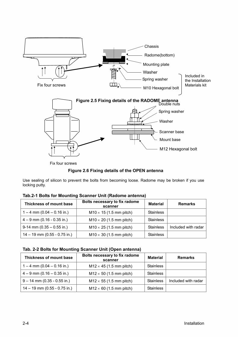
Use sealing of silicon to prevent the bolts from becoming loose. Radome may be broken if you use locking putty. Tab.2-1 Bolts for Mounting Scanner Unit (Radome antenna)
Thickness of mount base Bolts necessary to fix radome scanner Material Remarks
1 – 4 mm (0.04 – 0.16 in.) M10 × 15 (1.5 mm pitch) Stainless
4 – 9 mm (0.16 - 0.35 in.) M10 × 20 (1.5 mm pitch) Stainless
9-14 mm (0.35 – 0.55 in.) M10 × 25 (1.5 mm pitch) Stainless Included with radar
14 – 19 mm (0.55 - 0.75 in.) M10 × 30 (1.5 mm pitch) Stainless
Tab. 2-2 Bolts for Mounting Scanner Unit (Open antenna)
Thickness of mount base Bolts necessary to fix radome scanner Material Remarks
1 – 4 mm (0.04 – 0.16 in.) M12 × 45 (1.5 mm pitch) Stainless
4 – 9 mm (0.16 – 0.35 in.) M12 × 50 (1.5 mm pitch) Stainless
9 – 14 mm (0.35 - 0.55 in.) M12 × 55 (1.5 mm pitch) Stainless Included with radar
14 – 19 mm (0.55 - 0.75 in.) M12 × 60 (1.5 mm pitch) Stainless
Spring washer
Washer
M10 Hexagonal bolt
Radome(bottom)
Chassis
Included in the Installation Materials kit
Figure 2.5 Fixing details of the RADOME antenna
Fix four screws
Mounting plate
Figure 2.6 Fixing details of the OPEN antenna
Double nuts
Spring washer
Washer
M12 Hexagonal bolt
Mount base
Scanner base
Fix four screws
Installation 2-5
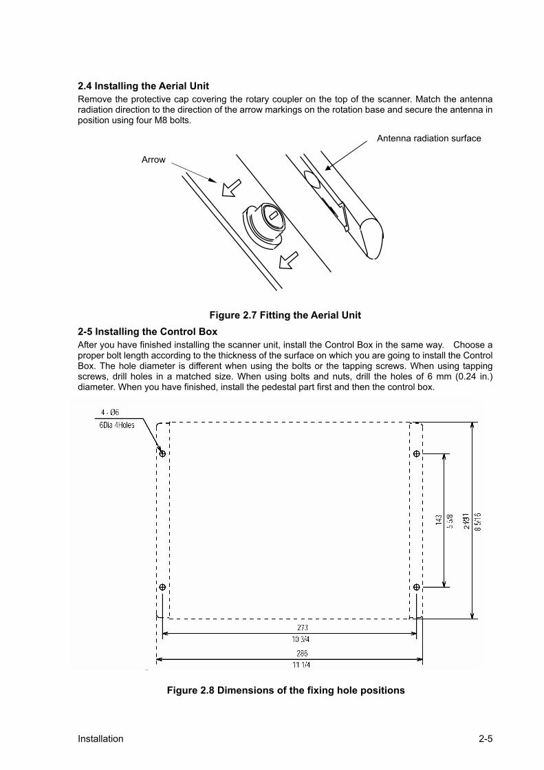
2.4 Installing the Aerial Unit Remove the protective cap covering the rotary coupler on the top of the scanner. Match the antenna radiation direction to the direction of the arrow markings on the rotation base and secure the antenna in position using four M8 bolts.
Figure 2.7 Fitting the Aerial Unit 2-5 Installing the Control Box After you have finished installing the scanner unit, install the Control Box in the same way. Choose a proper bolt length according to the thickness of the surface on which you are going to install the Control Box. The hole diameter is different when using the bolts or the tapping screws. When using tapping screws, drill holes in a matched size. When using bolts and nuts, drill the holes of 6 mm (0.24 in.) diameter. When you have finished, install the pedestal part first and then the control box.
2.6 Connecting the cables
Arrow
Antenna radiation surface
Figure 2.8 Dimensions of the fixing hole positions
4- Φ6 Holes
4-Φ1/4 Holes
213

2-6 Installation
2.6 Connecting the cables 2.6.1 General considerations (1) The cable connecting the Antenna and Control Unit should be run separately away from other
cables such as, radio antenna feeders, power cables, etc. Under no circumstances should it be in parallel arrangement with other cables. These precautions are essential to avoid radio interference to/from other equipment installed on the ship. If this is not possible, either cable set should be screened with metal conduit or another form of shielding.
(2) Cable should be run as short as possible but be kept within the standard length to achieve best radar performance.
(3) The copper braids of the cable must be grounded via a grounding stud in the transceiver unit.
2.6.2 Connections with RB715A 4 kW Radome 1) Make sure that the power is off. Connect the cable to the plug labeled "SCANNER" on the control
box unit. Be sure to secure the rubber boot around the cable connector rim.
2) Remove the radome cover from the Antenna unit by gently lifting upward to avoid bumping against the internal aerial. (There are four screws holding it in place.)
3) Remove the tape securing the antenna.
4) Remove the shield cover located on the backside. (There are four screws.)
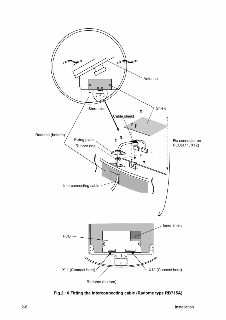
5) Remove the cable clamping plate and rubber ring, pass the cable through the opening, replace the rubber ring, and clamp the cable to the scanner unit with screws on the fixing plate. Attach the cable connector to the X11 and X12 connector on the printed circuit board.
6) Replace the aluminum cover. Lay the cable shield into the channel machined into the aluminum housing. Be careful that the cable will not get caught between the main unit and cover.
7) Replace the upper part of the radome, being careful not to bump it against the antenna. Make sure that the cover is positioned in the correct direction as shown in Figure 2.9. The upper and lower parts of the radome each have four alignment markings indicating screw positions.

Installation 2-7
Figure 2.9 Fitting the cover (Radome antenna)
Ship’s bow
Fix four screws
Cable inlet
Company logo seal on this side
Fixing screws
Ship’s bow
2-8 Installation
Fix connector on PCB(X11, X12)
Fig.2.10 Fitting the interconnecting cable (Radome type RB715A)
Rubber ring
Interconnecting cable
Radome (bottom)
Antenna
Stern side Shield
Cable shield
Fixing plate
X12 (Connect here)
Radome (bottom)
PCB
Inner shield
X11 (Connect here)

Installation 2-9
2.6.3 Cable connections for OPEN scanner (1) Make sure that the power is off. Connect the cable to the plug labeled "SCANNER" on the rear
panel of the display unit. Be sure to secure the rubber boot around the cable connector rim.
(2) Use a socket wrench to remove the back cover of the scanner unit.
(3) Remove the two bolts securing the transceiver.
(4) Remove the connectors to the motor (X1: RB716A, J5:RB717A/718A/719A) and to the heading switch (X2: RB716A, J3: RB717A/718A/719A ). Pull out the transceiver.
(5) Remove the four bolts securing the fixing plate at the cable entrance.
(6) Remove the metal fixing plate, rubber seal and the washer that secure the cable. Pass the cable through as shown in the diagram below; replace the above items and tighten the bolts.
(7) Return the transceiver to its original position and secure it with the bolts removed.
(8) Connect the 7-pin connector to X11 (RB716A)/J2 (RB717A/718A/719A ) and the 9-pin connector to X12 (RB716A)/J1 (RB717A/718A/719A) of the printed circuit board and connect the two connectors removed in Step 3).
(9) Replace the scanner cover. Make sure the cover does not pinch the cable when reattaching the cover.
Cable inlet
Fixing bolt
Inter-connection cable
TR unit fixing bolts Remove these connectors
Fixing bolt
Fixing plate
Inter-connection cable
Clamp
MAX 5 mm Scanner unit
Sealing rubber
Lay the braid under the fixing plate short as possible.
Figure 2.11 Fitting interconnecting cable (Open scanner)
Fixing plate
Cable shielding terminal washer
Remove any residual portion of the heat shrink tube when used.

2-10 Installation
2.7 Grounding wire 2.7.1 Grounding the Antenna Unit Connect a grounding wire from one of the bolts on the scanner base as shown in Figure 2.12. (The crimping terminal and grounding wire are user-supplied items.)
Figure 2.12 Grounding the Antenna Unit
Mount base Radome(bottom)
Chassis
→ To ship's hull
Crimping terminal
Grounding wire
Radome scanner
Grounding wire
→To ship’s hull
Scanner cover
Open scanner

Installation 2-11
2.8 Cable connections for Radar Control Box Unit 2.8.1 Antenna Unit connector pinouts The following diagrams show the pinouts of available scanner units connectors. The other end of the cable is connected to the SCANNER connector in the Control Box unit as shown.
RB715A: SCAN-RMD PCB (X11):RB716A/717A/718A:
SCAN-OPN PCB (X11) No Color Function
1 17 VIOLET +250V
2 NC
3 17 YELLOW GND
4 34 RED SHIP’S+
5 34 YELLOW SHIP’S+
6 34 GREEN SHIP’S-
7 34 BLUE SHIP’S- RB715A: SCAN-RMD PCB (X12) RB716A/717A/718A/719A: SCAN-OPN PCB (X12) No Color Function
1 17 BLUE +24V
2 NC
3 34 ORANGE +12V
4 Braid of RED DAT-R
5 RED DAT
6 Braid of
BROWN BP/SHF-R
7 BROWN BP/HG
8 Braid of GRAY V/TRG-R
9 GRAY V/TRG
Radar Sensor Control Box Unit
SCANNER
Scanner Unit connectors pinouts
Figure 2.13 Scanner unit – Connector pinouts

2-12 Installation
2.8.2 Control Box connector pinouts
Scanner connector pinouts No. Function
1 +250V
2 +24V
3 +12V
4 GND
5 DAT-R
6 DAT
7 N.C.
8 BP/SHF
9 BP/SHF-R
10 V/TRG
11 N.C.
12 SHIP'S+
13 SHIP'S+
14 V/TRG-R
15 SHIP'S-
16 SHIP'S-
Power connector pinouts No. Function Color
1 DC- Black
2 DC+ White
3 N.C. Green
4 N.C. Red
5 GND Grey
To optional external on/off switch
SCANNER POWER SUPPLY
NOTE: Mains supply voltage range varies according to the scanner type used as follows: RB715A/716A/717A/718A 10.2 to 41.6 VDC RB719A: 18.0 to 41.6 VDC
Radar Sensor Control Box Unit
Product label
POWER ON/OFF
(Front view)
Figure 2.14 Control Box unit – Connector pinouts (1)
Color
Blue
Green
NOTE: If no external switch is used, the connectors have to be shortened and insulated!

Installation 2-13
2.9 Power supply cable 2.9.1 On/Off Control Switch You may use the On/Off control switch provided or another style of switch if desired. If you choose to use a different style, it must be rated for 30 VDC or more and have a current carrying capacity of 0.1 A or higher.
The On/Off control switch does not carry the main power for operating the RADARpc scanner unit.
1) Route the green and blue wires to the location for the On/Off control switch.
2) If you choose to use the switch provided, refer to the diagram below to layout and cut a rectangular hole for the switch.
3) Pass the green and blue wires through the hole from behind the panel and connect the wires to the switch.
4) Press the switch into the mounting hole.
5) Place the On/Off control switch in the Off position.
No. Function
1 RD+
2 RD-
3 TD+
4 Termination
5 Termination
6 TD-
7 Termination
8 Termination
9 GND1
10 GND1
Ethernet connector pinouts
(Rear view)
Figure 2.15 Control Box unit – Connector pinouts (2)
Figure 2.16 On/Off switch - Fixing hole and connector pinouts

2-14 Installation
2.9.2 Power supply wiring
Power should be fed through a switch and protective fuses (or circuit breakers), as shown below.
Fit the power supply cable (included with your radar) to the receptacle labeled "POWER" on the rear panel of the control box and connect to power supply as followings. (When you do not connect external equipment, put tape on red and green wire.) Place the fuse and connection part in a dry area where there is no water splash. When extending the power supply cable, use a suitable cable as below.
Boat Power Voltage Cable conductor Cable max. length
3.5mm² 3m 12 VDC
3.5mm² 5m
3.5mm² 6m 24 VDC
3.5mm² 10m
Figure 2.18 Details of the Power Supply cable connections
Generator Switchboard Charger Storage Battery
12/24V
Main switch panel (Knife Switch with Fuses)
Control box
DC voltage reference points
CAUTION Do not apply over 41.6V to Radar or Radar may be broken.
White
Power supply cable
To control unit
DC-Black Gray
Green Red
DC+
Ground
No use
To power supply
Figure 2.17 Typical power supply switch wiring

Installation 2-15
2.10 Connecting the PC The connections of the Radar Sensor can be made straight to the PC or via an Ethernet Hub. Use the following instructions for connections.
2.10.1 Ethernet (LAN) interface cable connection Connection via the Ethernet Hub: Connect the Control Box to the Ethernet Hub unit with optional LAN cable (straight type, 2 m length). From the Hub unit to the PC, use a commercially available LAN cable (straight type) for connection. Connection without the Ethernet Hub:
Use the standard LAN cable (cross type, 2 m length) to connect the Radar Sensor to the PC.
Figure 2.19 Ethernet (LAN) Interface Cable Connection
Radome antenna: RB715A(4kw)
Remove any residual portion of the heat shrink tube when used.
Ethernet Hub
Transceiver: RB716A (4 kW) RB717A (6 kW) RB718A (12 kW) RB719A (25 kW)
GBxx BB
Navigation Receiver
Standard equipment
Customer supply items
Aerial: RW701A-03/04/06, RW701B-09
LAN interface Cable (2m)
(CAT 5) Crossover
cable (CAT 5)
Control Box RB50/RB60
GPS antenna

2-16 Installation
2.10.2 Details of LAN cable (1) Cable configuration (2) Connector pinouts Standard cable (Straight wiring)
NOTE: Spiral wound color code designation: Spiral color/Background color
Pin No. Signal name
1 RD+
2 RD-
3 TD+
4 NC
5 NC
6 TD-
7 NC
8 NC
Pin No. Signal name
1 RD+
2 RD-
3 TD+
4 NC
5 NC
6 TD-
7 NC
8 NC
3
Pin 8
Pin 1
Pin 1
Pin 8

Installation 2-17
Standard cable (Crossover wiring)
Pin No. Signal name
1 RD+
2 RD-
3 TD+
4 NC
5 NC
6 TD-
7 NC
8 NC
Pin No. Signal name
1 RD+
2 RD-
3 TD+
4 NC
5 NC
6 TD-
7 NC
8 NC

2-18 Installation
IP= 192.168.0.1
OnOn

Specifications Contents
Chapter 3
Specifications
Contents
Page No.
3.1 Radar sensor unit....................................................... 3-1 3.1.1 Antenna specification ................................................. 3-1 3.1.2 Interface specification (RB50/RB60 to PC) ................ 3-2 3.1.3 Power supply specification......................................... 3-2 3.1.4 Compass safe distance .............................................. 3-2 3.1.5 Environmental specification........................................ 3-3

Specifications 3-1
Chapter 3 Specifications
3.1 Radar Sensor Unit 3.1.1 Antenna Specification 4 k W 4 kW 6 kW 12 kW 25 kW
Aerial 2.0 feet Radome
3/4 feet Open Array
4/6 feet Open Array
4/6 feet Open Array
4/6/9 feet Open Array
Peak power output 4 kW 6 kW 12 kW 25 kW
Transmit frequency 9410 ± 30 MHz
Horizontal 3.9o 2.5/1.8o 1.8/1.2 1.8/1.2/0.8 Beam width Vertical 25° 22° 22°/22°/25°
Rotation 24/48 rpm
Short 0.08 sec/2000 Hz
Medium
Medium1
0.25/1000 0.25/1000 0.3/1500 0.3/1500 0.3/1300
Medium2 0.8/500 0.8/500 0.6/1000 0.6/1000 0.6/800
Long 1.0/500 1.0/500 1.2/500
Pulse length/PRF
Long2 1.2/400
IF center frequency 60 MHz
IF bandwidth Wide 20 MHz
Narrow 3 MHz
Noise figure 6.5 dB nominal
Operating temperature -25 oC to + 55 oC (-13oC to 131 oF)
Wind force 100 knots relative
Water resistance IPX6 (IEC60945)
Presentation Modes Heading up, North up, Course up
Range scales (nm) 1/8, 1/4, 1/2,
3/4, 1, 1.5,
2, 3, 4, 6, 8,
12, 16, 24,
36
1/8, 1/4, 1/2,
3/4, 1, 1.5,
2, 3, 4, 6, 8,
12, 16, 24,
36, 48
1/8, 1/4, 1/2,
3/4, 1, 1.5,
2, 3, 4, 6, 8,
12, 16, 24,
36, 48, 64,
1/8, 1/4, 1/2,
3/4, 1, 1.5, 2,
3, 4, 6, 8, 12,
16, 24, 36,
48, 64, 72
1/8, 1/4, 1/2,
3/4, 1, 1.5, 2,
3, 4, 6, 8, 12,
16, 24, 36,
48, 64, 72,
96
3-2 Specifications
Minimum range Better than 25 m (82 feet) on 1/8 nm range
Range discrimination Better than 25 m (82 feet)
Range accuracy Better than 8 m (26 feet) or 0.9% of maximum range of the scale in use
Bearing accuracy Better than 1o
Other functions Gain, STC, FTC, interference rejection, target expansion
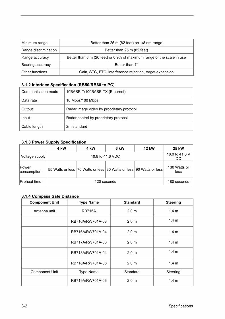
3.1.2 Interface Specification (RB50/RB60 to PC) Communication mode 10BASE-T/100BASE-TX (Ethernet)
Data rate 10 Mbps/100 Mbps
Output Radar image video by proprietary protocol
Input Radar control by proprietary protocol
Cable length 2m standard
3.1.3 Power Supply Specification
4 kW 4 kW 6 kW 12 kW 25 kW
Voltage supply 10.8 to 41.6 VDC 18.0 to 41.6 V DC
Power consumption 55 Watts or less 70 Watts or less 80 Watts or less 90 Watts or less 130 Watts or
less
Preheat time 120 seconds 180 seconds 3.1.4 Compass Safe Distance
Component Unit Type Name Standard Steering
Antenna unit RB715A 2.0 m 1.4 m
RB716A/RW701A-03 2.0 m 1.4 m
RB716A/RW701A-04 2.0 m 1.4 m
RB717A/RW701A-06 2.0 m 1.4 m
RB718A/RW701A-04 2.0 m 1.4 m
RB718A/RW701A-06 2.0 m 1.4 m
Component Unit Type Name Standard Steering
RB719A/RW701A-06 2.0 m 1.4 m

Specifications 3-3
RB719A/RW701B-09 2.0 m 1.4 m
Radar Sensor unit RB50 0.4 m 0.3 m
RB60 0.4 m 0.3 m
3.1.5 Environmental Specification To the requirements of IEC 60945 3rd Edition. The major environmental specifications are as follows:
(1) Temperature and humidity
Operating temperature Storage temperature Humidity
Antenna unit - 25oC - + 55oC + 77oC 93 % +/- 3 % at + 40oC
Radar Sensor unit - 15oC - + 55oC + 55oC 93 % +/- 3% at + 40oC
(2) Vibration
2-5 Hz up to 13.2 Hz: Amplitude +/- 1 mm +/- 10% (Maximum acceleration 7 m/s2 at 13.2 Hz)
13.2 Hz up to 100 Hz: Maximum acceleration 7 m/s2 constant
Technical references Contents
Chapter 4
Technical References
Contents
Page No.
4.1 Dimensions and weight................................................ 4-1

Technical references 4-1
Chapter 4 Technical References 4.1 Dimensions and weight RB715A Radome Antenna Unit

4-2 Technical references
RB716A Open Antenna Unit
104
4 1/
8
Technical references 4-3
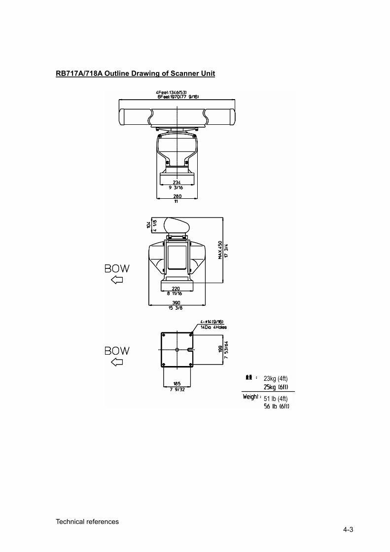
RB717A/718A Outline Drawing of Scanner Unit
23kg (4ft)
51 lb (4ft)

4-4 Technical references
RB719A Open Antenna Unit
4Feet, 1346 (53)
Weight: 27 kg (60 lb) for RW701-04 29 kg (64 lb) for RW701-06 33 kg (73 lb) for RW701-09 Unit in mm/inch

Technical references 4-5
RB50/RB60 Radar Control Box
Weight: RB50: 1.5 kg (3.3 lb) RB60: 1.9 kg (4.2 lb)

RB50/60.IM.E 0092642124-03

www.simradyachting.com