rastermapper version 4.0 alpha 3 user's...
TRANSCRIPT

RasterMAPPER™
Version 4.0 Alpha 3User’s Guide

RasterMAPPER Version 4.0 Alpha 3 User’s Guide 8 May 2009
RasterMAPPER™ User’s GuideSoftware Version 4.0 Alpha 3 (4.0.0.2620 Win, 4.0.0.2622 Mac)
Manual Rev. 1.2, 8 May 2009Part #117-0101
Copyright © Element Labs, Inc.
The Element Labs logo and RasterMAPPER™ are trademarks of Element Labs, Inc.
Other trademarks and trade names may be used in this document to refer to products by other entities. Element Labs, Inc. claims no proprietary interest in trademarks and trade names owned by others.
Information and specifications in this document are subject to change without notice. Element Labs, Inc. assumes no responsibility or liability for any errors or inaccuracies that may appear in this manual.
Warranty InformationRasterMAPPER and any associated software (collectively, “the Software”) is distributed WITHOUT ANY WARRANTY; without even the implied warranty of MERCHANTABILITY or FITNESS FOR A PARTICULAR PURPOSE. THERE IS NO WARRANTY FOR THE SOFTWARE, TO THE EXTENT PERMITTED BY APPLICABLE LAW. EXCEPT WHEN OTHERWISE STATED IN WRITING THE COPYRIGHT HOLDERS PROVIDE THE SOFTWARE “AS IS” WITHOUT WARRANTY OF ANY KIND, EITHER EXPRESSED OR IMPLIED, INCLUDING, BUT NOT LIMITED TO, THE IMPLIED WARRANTIES OF MERCHANTABILITY AND FITNESS FOR A PARTICULAR PURPOSE. THE ENTIRE RISK AS TO THE QUALITY AND PERFORMANCE OF THE SOFTWARE IS WITH THE USER. SHOULD THE SOFTWARE PROVE DEFECTIVE, THE USER ASSUMES THE COST OF ALL NECESSARY SERVICING, REPAIR OR CORRECTION. IN NO EVENT UNLESS REQUIRED BY APPLICABLE LAW OR AGREED TO IN WRITING WILL ELEMENT LABS OR ANY OF ITS AFFILIATES OR PARTNERS, BE LIABLE TO THE USER FOR DAMAGES, INCLUDING, BUT NOT LIMITED TO, ANY GENERAL, SPECIAL, INCIDENTAL OR CONSEQUENTIAL DAMAGES ARISING OUT OF THE USE OR INABILITY TO USE THE SOFTWARE (INCLUDING BUT NOT LIMITED TO LOSS OF DATA OR DATA BEING RENDERED INACCURATE OR LOSSES SUSTAINED BY THE USER OR THIRD PARTIES OR A FAILURE OF THE SOFTWARE TO OPERATE WITH ANY OTHER PROGRAMS), EVEN IF SUCH HOLDER HAS BEEN ADVISED OF THE POSSIBILITY OF SUCH DAMAGES.
ChangesElement Labs provides this manual ’as is’ without warranty of any kind, either expressed or implied, including but not limited to the implied warranties or merchantability and fitness for a particular purpose. Element Labs may make improvements and/or changes to the product(s) and/or the program(s) described in this publication at any time without notice.
This publication could contain technical inaccuracies or typographical errors. Changes are periodically made to the information in this publication; these changes are incorporated in new editions of this publication.

Preface iiiOverview _________________________________________________________ iiiTypographic Information ____________________________________________ iiiSystem Requirements ______________________________________________ iiiDownload/Install Info _______________________________________________ iv
Windows _____________________________________________________ ivMacintosh ____________________________________________________ iv
Help _____________________________________________________________ ivContact Info ______________________________________________________ vRelated Information ________________________________________________ vi
Chapter 1 : IntroductionVersion 4.0 Notes __________________________________________________ 1RasterMAPPER Basic Workflow _______________________________________ 2UI Overview ______________________________________________________ 3
Menu Bar _____________________________________________________ 4Toolbar _______________________________________________________ 5Fixture List ____________________________________________________ 6Map View _____________________________________________________ 7Inspector Panes ________________________________________________ 7
Chapter 2 : QuickStartRasterMAPPER QuickStart ___________________________________________ 8
Create and Send Map ___________________________________________ 8Enumerate PXL Fixtures ________________________________________ 10Retrieve Calibration Data from PXL Fixtures ________________________ 11
Chapter 3 : MappingOverview ________________________________________________________ 12Canvas __________________________________________________________ 13
Select Tool ___________________________________________________ 13Hand Tool ___________________________________________________ 13Zoom _______________________________________________________ 13Placing Fixtures _______________________________________________ 13
Fixture Operations ________________________________________________ 14Choosing Fixtures _____________________________________________ 14Creating Fixtures ______________________________________________ 14Moving Fixtures _______________________________________________ 15
Horizontal / Vertical _______________________________________ 15Rotation _________________________________________________ 15
TABLE OF CONTENTS
RasterMAPPER Version 4.0 Alpha 3 User’s Guide 8 May 2009 i

Duplicating Fixtures ___________________________________________ 16Duplicate Array _______________________________________________ 16
Grid Array _______________________________________________ 16Linear Array ______________________________________________ 17Circular Array _____________________________________________ 18
Sequencing ______________________________________________________ 19Layout Inspector __________________________________________________ 20
Port Pane ____________________________________________________ 20Geometry Pane _______________________________________________ 21Alignment Pane _______________________________________________ 21Map Transfer _________________________________________________ 22
Map Save/Open __________________________________________________ 22
Chapter 4 : Processor ControlOverview ________________________________________________________ 23Processor Selection _______________________________________________ 24Vizomo Processor Functionality _____________________________________ 25
Overview ____________________________________________________ 25Image Controls _______________________________________________ 26PXL Setup ____________________________________________________ 27
Enumeration Window ______________________________________ 27Retrieve Calibration Window ________________________________ 27
Processor Geometry ___________________________________________ 28Maps ________________________________________________________ 28Output ______________________________________________________ 29
Index 30
Table Of Contents
RasterMAPPER Version 4.0 Alpha 3 User’s Guide 8 May 2009 ii

PREFACE
OverviewRasterMAPPER™ has two main functions:
• Create a map which defines the relationship between pixels on the video source (typically a computer screen) and the actual Element Labs fixtures. After creating the map in RasterMAPPER it is uploaded and stored on the processor.
• Control and adjust the processor as needed.
This guide contains the following chapters:
• Chapter 1, Introduction, p. 1
• Chapter 2, QuickStart, p. 8
• Chapter 3, Mapping, p. 12
• Chapter 4, Processor Control, p. 23
Typographic InformationThis User’s Guide uses the following typographic conventions:
• menu items are displayed in Bold Italics
• clickable buttons are displayed in BOLD UPPER CASE.
• on-screen text is displayed in italics
• filenames & application names are displayed between “quote marks”
• keyboard keystrokes are displayed in Courier Font
System RequirementsRasterMAPPER software requires the following:
• Microsoft Windows® XP
or
• Mac OS X v10.5+, Intel Processor (PowerPC not supported)
with
• 1024 x 768 display (or larger),
• 10 MB of disk space minimum
• an ethernet port (to connect to a Vizomo processor)
Adobe® Reader® must be installed on your PC in order to use the RasterMAPPER Help menu item. Adobe® Reader® can be downloaded from http://www.adobe.com/products/acrobat/readstep2.html.
RasterMAPPER Version 4.0 Alpha 3 User’s Guide 8 May 2009 iii

Download/Install InfoFollow the steps below to install and run RasterMAPPER.
N O T E The downloaded .ZIP files must all be extracted to the same folder to run properly.
Windows1. Download RasterMAPPER software for Windows from the Element Labs website (http://
www.elementlabs.com/support.2. Extract/un-zip the files to the same folder.3. Double-click the file named RasterMAPPER.exe.
Macintosh1. Download RasterMAPPER software for Mac OS X from the Element Labs website (http://
www.elementlabs.com/support.2. Extract/un-zip the files to the same folder.3. Double-click the file named RasterMAPPER.
HelpHelp is available from within the RasterMAPPER application. Selecting RasterMAPPER Help from the HELP menu opens this manual. For further assistance, please see the Contact Info on the next page.
RasterMAPPER User’s Guide :: 8 May 2009, Manual Rev. 1.2 iv

Contact Info
Technical Support
Element Labs, Inc.9701 Metric Blvd., #200Austin, TX 78758tel +1 512 491 9111, option 2fax+1 512 491 9122
[email protected]://www.elementlabs.com
World Headquarters North America
Element Labs, Inc.2380 Owen St.Santa Clara, CA 95054tel +1 408 988 9400fax+1 512 491 9122
Element Labs, Inc.9701 Metric Blvd., #200Austin, TX 78758tel +1 512 491 9111fax+1 512 491 9122
Europe, Africa, Middle East, Asia United Kingdom
Element Labs GmbHLindener Str. 15D-38300 WolfenbüttelGermanytel +49 5331 905660fax +49 5331 905661
Element Labs Ltd.19A Perseverance Works38 Kingsland RoadLondon E2 8DDUnited Kingdomtel +44 (0) 20 7749 0611fax +44 (0) 20 7749 0622
RasterMAPPER User’s Guide :: 8 May 2009, Manual Rev. 1.2 v

Related InformationThe following links provide detailed information on various products mentioned in this manual.
Fixtures• Cobra™
- Information: http://www.elementlabs.com/cobra
- Manual: http://www.elementlabs.com/support
• Helix™ G75
- Information: http://www.elementlabs.com/helix
- Manual: http://www.elementlabs.com/support
Processors• Vizomo™
- Information: http://www.elementlabs.com/vizomo
- Manual: http://www.elementlabs.com/support
RasterMAPPER User’s Guide :: 8 May 2009, Manual Rev. 1.2 vi

C H A P T E R
Chapter 1: INTRODUCTION
The following topics are covered in this chapter:
• Version 4.0 Notes, p. 1
• RasterMAPPER Basic Workflow, p. 2
• UI Overview, p. 3
Version 4.0 NotesThe Version 4.0 upgrade to RasterMAPPER has completely updated the interface and refined the workflow. This manual will goes detail on all of the new features. The following list highlights some of the new and improved functionality:
• Unified view of fixture list, map, and processor controls.
• Multiple maps can be open at the same time.
• Copy / paste fixtures between open maps.
• Inspector panels allow quick access to common tasks.
• More keyboard shortcuts added.
• Ports now function like layers in graphics applications.
• Custom fixtures can be saved as templates.
• Enhanced Integration with Vizomo™ Video Processors:
- Multiple processor support
- Send map from Vizomo
- PXL Fixture enumeration
- Get PXL fixture calibration
RasterMAPPER Version 4.0 Alpha 3 User’s Guide 8 May 2009 1

Chapter 1:Introduction
RasterMAPPER Basic WorkflowThe chart below illustrates the basic RasterMAPPER workflow.
N O T E If using PXL protocol fixtures such as Cobra, the first time you upload a map and/or add or remove fixtures, you must then enumerate and retrieve the calibration data. See PXL Setup, (p. 27) for more information on enumeration and calibration.
RasterMAPPER Version 4.0 Alpha 3 User’s Guide 8 May 2009 2

Chapter 1:Introduction
UI OverviewThe following illustration identifies the major sections of the RasterMAPPER user interface. Details of each section follow.
Menus for RasterMAPPER functions listing keyboard shortcuts, where applicable.
Tools for various operations including showing/hiding the Fixture List and Inspector Panes.
Listing of all fixtures and associated information contained on the current map.
The work grid view of the current map includes color-coding and opacity indicating individual, grouped, and hidden fixtures.
Inspector panes organize various functions grouped into 2 sections: layout and configuration.
1
2
3 54
1 Menu Bar
2 Toolbar
3 Fixture List
4 Map View
5 Inspector Panes
RasterMAPPER Version 4.0 Alpha 3 User’s Guide 8 May 2009 3

Chapter 1:Introduction
Menu BarThe menu bar is displayed at the top of the application and allows access to various features. If applicable, a keyboard shortcut is displayed.
Here are some of the menus:
RasterMAPPER Version 4.0 Alpha 3 User’s Guide 8 May 2009 4

Chapter 1:Introduction
ToolbarThe toolbar provides functionality for collapsing the fixture list and inspector panes as well as map view tools.
1 2 3 4
1 The Fixture List button displays or hides the Fixture List pane. When hidden, more room is given to the map view.
Hidden
Displayed
2 The tools area contains the following:
Select Fixture
Add/Edit Fixture
Hand Tool
The add fixture button is also a menu allowing you to choose a factory fixture or edit the menu to add a custom fixture.
a a b c
b
cc
d
d
3 The zoom slider tool magnifies or reduces the map view. Hold the cursor over the zoom tool to see the current setting.
4 Inspectors are grouped into two categories that can be displayed or hidden by clicking the Layout or Configure buttons.
Hidden
Displayed
If a group is already visible, clicking the button again will hide all inspectors, giving more area to the map view.
RasterMAPPER Version 4.0 Alpha 3 User’s Guide 8 May 2009 5

Chapter 1:Introduction
Fixture ListThe fixture list shows port, sequence, and address information for all fixtures in the map. Additionally, specific information about the selected fixture is displayed.
1
Fixtures on hidden ports are displayed in gray text.3
Click on any fixture to highlight it both in the list and in the map view. Click the triangle to the left of a port or fixture to show or hide the fixtures or pixels below.
You can navigate up and down the list by using the corresponding keyboard arrow keys. The right and left arrow keys display or hide the encompassing pixels or fixtures.
5
Information about the currently selected fixture is displayed at the top of the fixture list.
The currently selected fixture is highlighted in the list.2
4 Unused and unassigned ports are also displayed in gray text.
1
2
3
4
5
RasterMAPPER Version 4.0 Alpha 3 User’s Guide 8 May 2009 6

Chapter 1:Introduction
Map ViewThe map view displays fixtures currently placed on the work grid.
Inspector PanesThe inspector panes section of the user interface provide control over many parameters and are grouped into 2 types based on functionality: Layout and Configure.
1 Fixtures placed on the work grid are displayed in their specified colors. The fixture is slightly transparent to allow the work grid to be displayed underneath.
Selected fixtures are highlighted in green. The rotation handles are indicated on the corners and the center of rotation is indicated by a dot.
2
1
3
2
Fixtures on hidden ports are nearly transparent.3
If Snap is turned on in the Geometry inspector, the work grid shows the x and y values as bold lines.
4 4
1
4
3
2
1 Click the group buttons to show or hide the inspectors for that group. If a group is already displayed, the entire inspector pane will be hidden from view giving more room to the map view.
2 Individual inspector panes can be collapsed and hidden from view when desired by clicking the triangle next to the inspector title.
3 If more panes exist than can be displayed on screen, a scrollbar automatically appears.
4 A button at the bottom of the inspector panes allow you to send a map to the processor. This button is not scrollable and will always be in view.
RasterMAPPER Version 4.0 Alpha 3 User’s Guide 8 May 2009 7

C H A P T E R
Chapter 2: QUICKSTART
RasterMAPPER QuickStartThe following basic information will get up and running quickly with RasterMAPPER Version 4.0 Alpha 3. The steps involved are only those necessary to create a map, send it to the processor, and ensure the fixtures are configured properly on the processor. These steps are based on the RasterMAPPER Basic Workflow, p. 2, using Element Labs’ Vizomo video processor and Cobra 16 fixtures.
Create and Send Map1. Download and Install RasterMAPPER (see Download/Install Info, p. iv).2. Launch RasterMAPPER. A new window opens with a blank map.
3. Select Cobra 16 from the fixture menu.
RasterMAPPER Version 4.0 Alpha 3 User’s Guide 8 May 2009 8

Chapter 2:QuickStart
4. Place fixtures on the work grid as required.
5. Save the map to your hard drive as a backup.
6. Click the SEND MAP… button.
7. Choose the desired processor from the pull-down menu.
8. Choose PXL Fixture Map from the Automatically assign as current… pull down menu.
9. Click EXPORT button.
RasterMAPPER Version 4.0 Alpha 3 User’s Guide 8 May 2009 9

Chapter 2:QuickStart
N O T E If you are using fixtures with the PXL protocol, such as Cobra 16 or 11, and this is the first time you have uploaded a map to the Vizomo, you will also need to perform the steps below.
Enumerate PXL Fixtures10. Click the CONFIGURE tab.
11. In PXL Setup section, click ENUMERATE.
12. Click the radio button for Enumerate All Fixtures.
13. Click the ENUMERATE button.14. Check the status area for any errors.
RasterMAPPER Version 4.0 Alpha 3 User’s Guide 8 May 2009 10

Chapter 2:QuickStart
15. When the status area reads “Success (returned 0)”, click the red X in the upper corner (Win) or the CANCEL button (Mac) to close the window.
Retrieve Calibration Data from PXL Fixtures16. Click RETRIEVE… button.
17. Click the RETRIEVE button to begin the process.
18. Check the status area for any errors.19. When the status area reads Success (returned 0), click the red X in the upper corner (Win)
or the CANCEL button (Mac) to close the window.
Mac Win
Mac Win
RasterMAPPER Version 4.0 Alpha 3 User’s Guide 8 May 2009 11

C H A P T E R
Chapter 3: MAPPING
The following topics are discussed in this chapter:
• Overview, p. 12
• Canvas, p. 13
• Fixture Operations, p. 14
• Sequencing, p. 19
• Layout Inspector, p. 20
• Map Save/Open, p. 22
OverviewMapping involves choosing existing fixtures or creating new ones and placing them on the work grid in the same order as they are in real life.
The processing equipment may contain multiple output ports for fixtures. RasterMAPPER allows you to select which port fixtures are assigned. Additional functionality allows you to electronically change the wiring order of the fixtures by resequencing.
RasterMAPPER Version 4.0 introduces the ability to have multiple maps open at the same time. Each can be saved or opened independently of each other and fixtures can be copied between maps.
RasterMAPPER Version 4.0 Alpha 3 User’s Guide 8 May 2009 12

Chapter 3:Mapping
CanvasThe work grid or canvas in RasterMAPPER is where you place fixtures. When you first launch RasterMAPPER, a blank canvas is displayed. Once you begin placing fixtures, they appear in a unique color. Fixtures on an inactive port have much greater transparency.
There are several tools and features specific to the canvas.
Select ToolThe select tool ( ) allows you to choose any fixture or group of fixtures on an active port. You can select fixtures in several ways:
• Click and drag across the canvas. Start with the cursor in an empty part of the grid or you will move a fixture.
• Click on the first fixture, then press and hold Shift (Win or Mac), Control (Win), or Command (Mac) and click on the next fixture. Only those two fixtures will be selected.
Hand ToolThe hand tool ( ) and scrollbars allow you to move the canvas around to see various sections of the display. You can click and drag a scrollbar or click in the area above and below the scrollbar to move the canvas.
ZoomAdjust the zoom slider ( ) to magnify or reduce the viewable canvas in preset values from 8-800%.
Placing FixturesThe add fixture tool ( ) is also a menu allowing you to choose a fixture and then add it to the canvas.
To place a fixture, first check the port pane and make sure you are adding fixtures to the desired port and that it is enabled (see Port Pane, p. 20 for more information).
Next, click and hold the triangle next to the fixture name in the tools section of the window to display the fixture list. Navigate to the desired fixture and release the mouse to select that fixture.
Then, click on the canvas where your fixtures are located and in the order they are wired (sequence). You can change the sequence later, if desired (see Sequencing, p. 19 for more information).
N O T E If you try to place a fixture on a hidden port, the cursor changes to an X and the color of the fixture being placed changes to red. See Port Pane, p. 20 for more information on hidden ports.
RasterMAPPER Version 4.0 Alpha 3 User’s Guide 8 May 2009 13

Chapter 3:Mapping
Fixture OperationsRasterMAPPER provides a default list of Element Labs’ fixtures to use. You can also create new fixtures that can be saved with the current map or as a template fixture to be used with any map. If a custom fixture is created in a map and opened on another computer without that custom fixture, it will be automatically added to the current map.
Choosing FixturesClick and hold on the triangle next to the fixture name in the tools section of the window. The fixture list appears allowing you to choose a factory fixture or create your own. To select a factory fixture, simply release the mouse on the fixture you would like to use.
Creating FixturesTo create a custom fixture, choose Edit this Menu… from the fixture menu. The choices for editing fixtures are as follows.
Either choice above opens the basic Fixture Setup window with the following information.
1 Click the PLUS button to create a new fixture.
2 Select a fixture and click DUPLICATE to create a copy of an existing fixture that you can then edit.
or
1 2
1 Fixture names must be unique and can contain any combination of alphanumeric characters, including spaces.
1
2
34
56
2 Width and height parameters are set by entering a number in the text box or clicking the up or down arrows.
Click the triangle to the left of Advanced to show or hide advanced fixture setup options.
3
Click SAVE AS TEMPLATE to save this custom fixture to a file on the computer. Template fixtures load whenever RasterMAPPER is launched and are saved to the following locations:
• Win: “Documents and Settings\user\Application Data\RasterMAPPER\Templates\”
• Mac: “~/Library/Application Support/RasterMAPPER/templates/”
4
Click SAVE TO MAP to save this custom fixture to the current map. This fixture will not be loaded the next time RasterMAPPER is launched. However, if a map with a custom fixture is loaded, it will be placed in the Custom section of the fixture menu.
Click the Cancel button to close the window without creating a custom fixture.6
5
RasterMAPPER Version 4.0 Alpha 3 User’s Guide 8 May 2009 14

Chapter 3:Mapping
The advanced options in the Fixture Setup window include the following:
Moving Fixtures
Horizontal / Vertical• Mouse: click on one of the selected fixtures and drag it to a new location. If Overlap is
turned off, you will not be able to place one fixture over another (see Alignment Pane, p. 21 for more information).
• Keyboard: press the desired arrow key to move the selected fixture(s) in any direction on the canvas.
• Geometry Pane: enter explicit x-axis and y-axis values for the fixture(s). See Geometry Pane, p. 21.
Rotation• Mouse: position the cursor over one of the corners of the box
surrounding the selection and click and drag to rotate the selected fixture(s). The cursor changes to indicate the possible direction of rotation.
• Geometry Pane: enter an explicit rotation value for the fixture(s). See Geometry Pane, p. 21.
N O T E It is not possible to move or rotate fixtures so any part is off the canvas.
1 Virtual width and height parameters are set by entering a number in the text box or clicking the up or down arrows.Not implemented yet.
1
3
2 Default rotation is set by entering a number in the text box of clicking the up or down arrows. Not implemented yet.
The background color can be defined for custom fixtures by clicking the colored button. The standard color picker will open, allowing you to choose a color.
4
Click the Scan Order icon to choose from a list of possible scan orders for the fixture.
3 2
4
RasterMAPPER Version 4.0 Alpha 3 User’s Guide 8 May 2009 15

Chapter 3:Mapping
Duplicating FixturesThere are a couple of ways to duplicate selected fixtures.
• Choose Duplicate from the Edit menu, or press Command + D (Mac), Control + D (Win) to place a copy of the fixture(s) on the canvas to the right of the selected fixture(s).
If there is no space next to the selected fixture(s) the duplicated fixture(s) will be placed below.
• Press the Option key and drag a copy of the fixture(s) to a new location.
Duplicate ArraySelecting Duplicate Array… from the Edit menu opens a dialog box with options for three Array Duplication modes.
Grid Array
1 Enter the number of rows and columns the resulting array will be.
12 Choose the new scan order for the resulting array.
2
3
3 Enter the desired column and row offset between each duplicated array.
RasterMAPPER automatically sets the offsets based on the width and height of the selected fixtures (objects), but you can enter your own, if desired.
Before After
RasterMAPPER Version 4.0 Alpha 3 User’s Guide 8 May 2009 16

Chapter 3:Mapping
Linear Array
1 Enter the total number of fixtures for the resulting array.
12 Enter the X (horizontal) and/or Y
(vertical) offsets for the resulting array. Each new fixture will be this number of pixels away from each other.
RasterMAPPER automatically sets the offsets based on the width and height of the selected fixtures (objects), but you can enter your own, if desired.
2
Before After
RasterMAPPER Version 4.0 Alpha 3 User’s Guide 8 May 2009 17

Chapter 3:Mapping
Circular Array
1 Enter the total number of fixtures you would like in the new array. 1
2 Based on the count, the Separation angle and Fixture rotation is computed and displayed for you.
2
3
3 Enter the desired Radius (in pixels) for the new array.
Before After
RasterMAPPER Version 4.0 Alpha 3 User’s Guide 8 May 2009 18

Chapter 3:Mapping
Sequencing
1 New port to which the selected fixtures will be moved.
2 New sequence number to start the resequencing. The current sequence number is displayed.
3 Press SHIFT UP / DOWN to have the newly sequenced fixture “inserted” into its new sequence location. All of the other fixtures between the two locations are shifted up or down one position.
The wiring order or sequence determines the order of the pixels output from the processor. Individual fixtures are assigned an address as they are added to the grid but the sequence may be changed afterwards.
Select the fixture(s) you wish to resequence and choose Resequence… from the Edit menu or press Command + R (Mac), Control + R (Win). The current sequence number is displayed.
Options for resequencing include:
1 2
3 4 5
4 Press SWAP to have the newly sequenced fixture replace a fixture that already had that port/sequence information. The replaced fixture is reassigned to the old location.
5 Press CANCEL to close the window without resequencing.
1
RasterMAPPER Version 4.0 Alpha 3 User’s Guide 8 May 2009 19
Chapter 3:Mapping
Layout Inspector
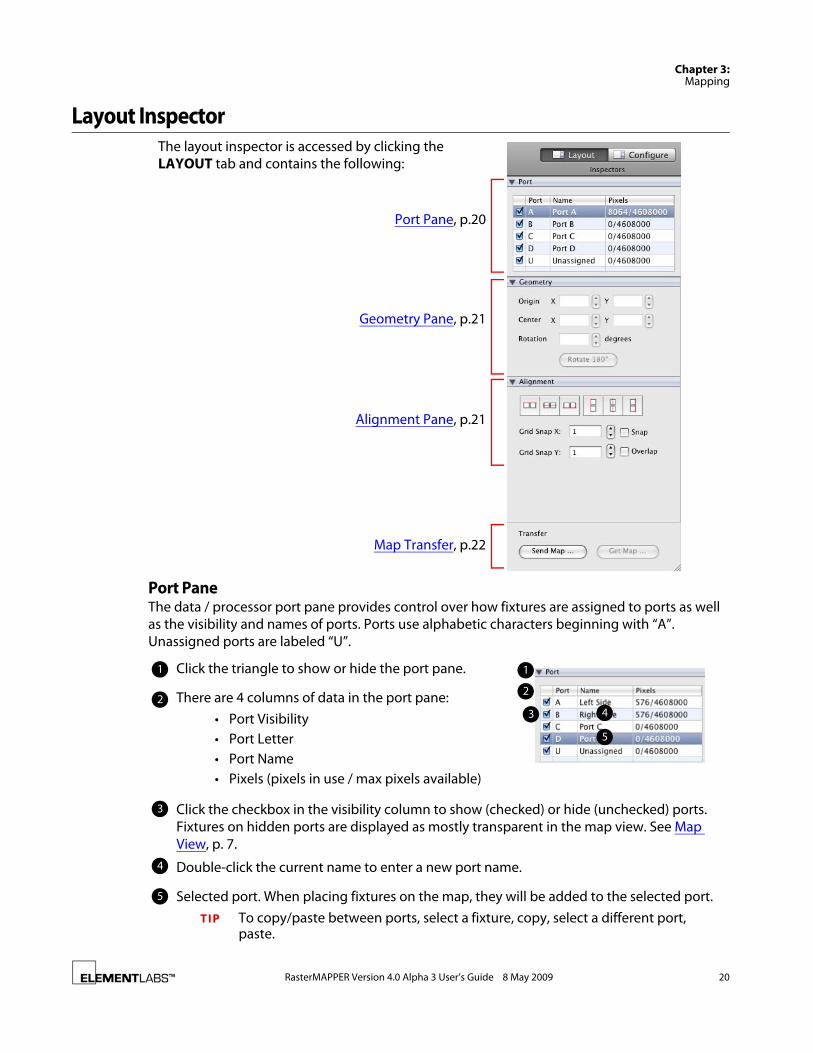
Port PaneThe data / processor port pane provides control over how fixtures are assigned to ports as well as the visibility and names of ports. Ports use alphabetic characters beginning with “A”. Unassigned ports are labeled “U”.
Port Pane, p.20
Geometry Pane, p.21
Alignment Pane, p.21
Map Transfer, p.22
The layout inspector is accessed by clicking the LAYOUT tab and contains the following:
3
Double-click the current name to enter a new port name.
There are 4 columns of data in the port pane:• Port Visibility• Port Letter• Port Name• Pixels (pixels in use / max pixels available)
22
1
3 4
1 Click the triangle to show or hide the port pane.
Click the checkbox in the visibility column to show (checked) or hide (unchecked) ports. Fixtures on hidden ports are displayed as mostly transparent in the map view. See Map View, p. 7.
4
5
Selected port. When placing fixtures on the map, they will be added to the selected port.TIP To copy/paste between ports, select a fixture, copy, select a different port,
paste.
5
RasterMAPPER Version 4.0 Alpha 3 User’s Guide 8 May 2009 20

Chapter 3:Mapping
Geometry PaneThe geometry pane provides functionality to move and rotate fixtures within the canvas.
N O T E If the selected fixture are rotated, the origin boxes are inaccessible. Use the Center values to move the fixture.
Alignment PaneThe alignment pane is used to set x and y snap values and enable/disable grid snap and overlay. Snapping limits the placement of fixtures to within only a certain number of pixels, commonly the width/height of the fixture.
1 Click the triangle to show or hide the geometry pane. 1
2Click into either the Origin X or Origin Y text box and type a value for the origins of the selected fixture(s).
These values correspond to the upper left pixel of a rectangular fixture and the left pixel of a linear fixture.
2
Click the up or down triangles to increment or decrement the value, respectively.3
3
Click into the Center X or Center Y text boxes or use the up/down arrows to enter a value for the center of the selected fixture(s).
4
Click the Rotate 180° button to rotate the selected fixture(s) clockwise 180°.6
4
6
Click into the Rotation text box or use the up/down arrows to enter a rotation value.5
5
1 Click the triangle to show or hide the alignment pane. 1
Click into either the Grid Snap X or Grid Snap Y text box and type a value for the origins of the selected fixture(s).
If enabled with a value greater than 1, the snap amount is illustrated in the map view by thicker grid lines. See Map View, p. 7.
2
2
Click the up or down triangles to increment or decrement the value, respectively.3
3
Enable the Snap feature by checking the box.4
Enable the Overlap feature by checking the box. Overlap allows fixtures to be placed on top of or behind another fixture.
5
4
5
RasterMAPPER Version 4.0 Alpha 3 User’s Guide 8 May 2009 21

Chapter 3:Mapping
Map TransferThe Transfer section contains buttons for sending maps to the processor. Click the SEND MAP … button to open the map upload window.
The map upload/export window contains the following items:
Map Save/OpenRasterMAPPER launches with a new, empty map. You can open existing maps and save the current map by using the File menu.
N O T E Don’t forget that in RasterMAPPER v4.0 you can have multiple maps open at the same time. This allows you enhanced functionality like copying and pasting fixtures from one map to another.
1
2
1 Choose a processor from the pull-down menu.
2 If saved locally to your computer, the map name will be displayed. You can modify that name or specify a different name for the uploaded map.
3
4 53 After uploading, you can specify if the uploaded map should be assigned as the current map.
4 The Cancel button exits the map uploading process.
5 The Export button uploads the map.
RasterMAPPER Version 4.0 Alpha 3 User’s Guide 8 May 2009 22
C H A P T E R
Chapter 4: PROCESSOR CONTROL
The following topics are discussed in this chapter:
• Overview, p. 23
• Processor Selection, p. 24
• Vizomo Processor Functionality, p. 25
OverviewRasterMAPPER provides control over many functions on the Vizomo processor via the Configure Inspectors. Some parameters are sent instantly to the processor resulting in an immediate change. Other parameters are not sent until you expressly push a button or otherwise commit the changes.
For more information on the Vizomo processor, please refer to the Vizomo User’s Guide, available in the support section of Element Labs’ website: http://www.elementlabs.com/support.
RasterMAPPER Version 4.0 Alpha 3 User’s Guide 8 May 2009 23

Chapter 4:Processor Control
Processor SelectionRasterMAPPER provides the functionality to control different processors from the same interface. A processor select drop-down menu is displayed, when required, to choose the processor you wish to control.
Click and hold the processor menu to list the Vizomo processors found on your local area network.
Figure 4.1 Processor Select Menu Examples
RasterMAPPER Version 4.0 Alpha 3 User’s Guide 8 May 2009 24

Chapter 4:Processor Control
Vizomo Processor Functionality
OverviewThe Configure inspector pane provides access to Vizomo processor functions. Most sections of the pane contain a triangle to the left of the section name allowing you to close or open that section. This gives you the flexibility to hide little used sections while ensuring frequently used ones remain visible. Additionally, if the screen size does not accommodate all the inspectors, scrollbars will appear. The top and bottom sections are always visible and will not scroll out of view.
The sections of the Configure pane are:
Processor Selection, p.24
Image Controls, p.26
Maps, p.28
Output, p.29
PXL Setup, p.27
Processor Geometry, p.28
RasterMAPPER Version 4.0 Alpha 3 User’s Guide 8 May 2009 25

Chapter 4:Processor Control
Image ControlsThe Image inspector pane contains the following controls.
TIP Click the preset values displayed above the slider to instantly jump to that preset.
Item Min Max Default Notes
Brightness 0 1.0 1.0
Gamma 1.0 3.0 2.2
Color Temp. 4000K 10,000K 6500K
Gamut -- -- Cobra Extended Menu choices: HDTV Rec. 709, Cobra Extended
Global Tint (R,G,B)
0 1.2 1.0 Individual controls for Red, Green, and Blue
Cobra 16 virtual resolution
-- -- None Menu choices: Virtual 8 mm, none
Defaults… Restores all image controls to factory default settings.
1
2
3
4
5
6
7
1
2
3
4
5
6
7
RasterMAPPER Version 4.0 Alpha 3 User’s Guide 8 May 2009 26

Chapter 4:Processor Control
PXL SetupThe PXL Setup inspector pane contains the following items.
N O T E If you are using fixtures with the PXL protocol, such as Cobra 16 or 11, and this is the first time you have uploaded a map to the Vizomo, you must enumerate and retrieve the calibration data.
N O T E The retrieve calibration process takes approximately 5 seconds per fixture.
1
2
1 Opens the Enumerate window.
2 Opens the Retrieve calibration window.
1
Enumeration Window
Poll all ports connected to the processor and enumerate all fixtures found.
Only enumerate fixtures beginning with a specific address, on a specific PXL switch port.
2 1
2
3
4
6
Only enumerate fixtures on a specific PXL switch.
3
Status messages from Vizomo.4
Click the ENUMERATE button to initiate the process.6
5Cancel/close the enumeration window. This does NOT terminate the process.
5
1
Retrieve Calibration Window
1
2 Cancel/close the calibration window. This does not terminate the process.
3 Click the RETRIEVE button to initiate the process. 32
Status messages from Vizomo.
RasterMAPPER Version 4.0 Alpha 3 User’s Guide 8 May 2009 27

Chapter 4:Processor Control
Processor GeometryThe Processor Geometry inspector pane contains the following items.
MapsThe Maps inspector pane contains the following items.
Click the UPLOAD… button to display the Map Upload/Export window with the following items.
1
2
1 Specify the width and height of the Vizomo canvas.
2 Choose the DVI output resolution and orientation.
3
3 Identify the DVI outputs.
1
2
1 Uploads the current map to the processor.
2 Select which map on the processor is to be used as the PXL fixture, DVI fixture, and DVI displacement map.
1
2
1 Choose a processor from the pull-down menu.
2 If saved locally to your computer, the map name will be displayed. You can modify that name or specify a different name for the uploaded map.
3
4 53 After uploading, you can specify if the uploaded map should be assigned as the current map.
4 The CANCEL button stops the map uploading process and closes the window.
5 The EXPORT button uploads the map. The window will close when finished.
RasterMAPPER Version 4.0 Alpha 3 User’s Guide 8 May 2009 28

Chapter 4:Processor Control
OutputThe Output inspector pane at the bottom of the processor configuration inspector does not scroll and contains the following items.
11
2
Blanks or unblanks the video output. A blank output will appear black. The output will resume displaying video when unblanked.
When the output is blanked, the button is shaded.
2
RasterMAPPER Version 4.0 Alpha 3 User’s Guide 8 May 2009 29

AAdd Fixture Tool, 13Add/Edit Fixture Tool, 5Array
Circular, 18Grid, 16Linear, 17
BBackground Color, 15Basic Workflow, 2Blank Outputs, 29Brightness, 26
CCanvas, 13Canvas Size (Vizomo), 28Choosing Fixtures, 14Circular Array, 18Cobra, vi, 2Cobra 16 Virtual Resolution, 26Color Temp, 26Column Offset, 16Configure Inspector, 5, 25Contact Info, vCreate a New Fixture, 14Custom Fixtures, 14
DDefault Rotation, 15Defaults, 26Duplicate Array, 16Duplicating Fixtures
Fixture Duplicate, 16DVI Output Resolution, 28
EEnumeration, 27Export, 28
FFactory Fixtures, 14
FixtureEnumeration, 27List, 5, 14Menu, 5Rotation, 15Select Tool, 13Setup Window, 14Template, 14
GGamma, 26Gamut, 26Geometry Pane, 15Global Tint, 26Grid Array, 16
HHand Tool, 5, 13HDTV Rec. 709, 26Helix G75, viHelp, ivHidden Port, 13Horizontal Offset, 17
IImage Controls, 26Inactive Port, 13Inspector panes, 3
LLayout Inspectors, 5Linear Array, 17
MMap Upload/Export, 28Mapping Overview, 12Maps Inspector, 28Menu Bar, 4Move Canvas, 13Moving Fixtures, 15
NNew Fixture, 14
INDEX
RasterMAPPER Version 4.0 Alpha 3 User’s Guide 8 May 2009 30

OOffset
Column, 16Horizontal, 17Row, 16Vertical, 17
Output Inspector, 29Overlap, 15
PPlacing Fixtures, 13Port Pane, 13Processor Control, 23Processor Geometry, 28Processor Selector, 24PXL Protocol, 2PXL Setup, 27PXL Switch, 27
QQuickStart, 8
RR,G,B Tint, 26Radius, 18Related Information, viRetrieve Calibration, 27Rotation, 15Row Offset, 16
SSave as Template, 14Save to Map, 14Scan Order, 15Select Fixture Tool, 5Select Tool, 13Selecting a Processor, 24System Requirements, iii
TTemplate Fixtures, 14Toolbar, 5Typographic Information, iii
VVersion 4.0 Software Notes, 1Vertical Offset, 17Virtual Resolution (Cobra 16), 26Virtual Width & Height, 15Vizomo, vi, 23Vizomo Processor Functionality, 25
WWork Grid, 13Workflow, 2
ZZoom, 13Zoom Slider, 5
Index
RasterMAPPER Version 4.0 Alpha 3 User’s Guide 8 May 2009 31