raspberry pi touchscreen tablet (pi pad)
TRANSCRIPT
International Journal on Recent and Innovation Trends in Computing and Communication ISSN: 2321-8169 Volume: 3 Issue: 2 600 - 605
_______________________________________________________________________________________________
600 IJRITCC | February 2015, Available @ http://www.ijritcc.org
_______________________________________________________________________________________
Raspberry Pi Touchscreen Tablet (Pi-Pad)
R Dharmateja
M. Tech Embedded System Technology,
Dept. of Electronics and Communication Engineering,
SRM University-Kattankulathur Campus,
Chennai, Tamilnadu, INDIA.
Dr. A. Ruhan Bevi
Assistant Professor(Ph.D)
Dept. of Electronics and Communication Engineering,
SRM University-Kattankulathur Campus, Chennai, Tamilnadu, INDIA.
Abstract—The Raspberry Pi is a credit card sized single-board computer developed in UK by Raspberry Pi foundation with the intention of
promoting the teaching of basic computer science in school. Now a days none of the tablets that are available in the market are of Linux OS. In this paper we showcase our attempt at building a low cost stand-alone device called Pi-pad which is very much helpful for educational purpose
using the Raspberry Pi as its brain with Bluetooth for connecting peripherals and communicating with local devices like Wi-Fi, keyboard and mouse. It has a touch screen display providing a user interface. The Raspberry Pi Tablet is controlled by a modified version of Debain Linux called Raspbian Wheezy OS optimized for the ARM architecture. The display contains a graphical interface which provides various fields for data entry via onscreen keyboard. Also, in this paper we use Linux commands and python programming for operating and interfacing the hardware.
Keywords—Raspberry pi; Linux OS; Python; Wi-fi; ARM; Raspbian; Touchscreen.
__________________________________________________*****_______________________________________________
I. INTRODUCTION
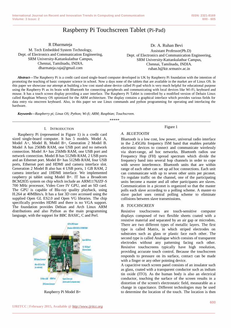
Raspberry Pi (represented in Figure 1) is a credit card sized single-board computer. It has 5 models. Model A, Model A+, Model B, Model B+, Generation 2 Model B. Model A has 256Mb RAM, one USB port and no network connection. Model A+ has 256Mb RAM, one USB port and network connection. Model B has 512Mb RAM, 2 USB ports and an Ethernet port. Model B+ has 512Mb RAM, four USB ports, Ethernet port and HDMI and camera interface slot. Generation 2 Model B also has 4 USB ports, 1 GB RAM, 2 camera interface and 1HDMI interface. We implemented raspberry pi tablet using Model B+. IT has a Broadcom BCM2835 system on chip which include an ARM1176JZF-S 700 MHz processor, Video Core IV GPU, and an SD card. The GPU is capable of Blu-ray quality playback, using H.264 at 40MBits/s. It has a fast 3D core accessed using the supplied Open GL ES2.0 and Open VG libraries. The chip specifically provides HDMI and there is no VGA support. The foundation provides Debian and Arch Linux ARM distributions and also Python as the main programming language, with the support for BBC BASIC, C and Perl.
Raspberry Pi Model B+
Figure 1
A. BLUETOOTH
Bluetooth is a low cost, low power, universal radio interface in the 2.45GHz frequency ISM band that enables portable electronic devices to connect and communicate wirelessly via short-range, ad hoc networks. Bluetooth radios use Frequency Hop (FH) spread spectrum which divide the frequency band into several hop channels in order to cope with severe interference. Bluetooth units that are within range of each other can set up ad hoc connections. Each unit can communicate with up to seven other units per piconet. To regulate traffic on the channel, one of the participating units become a master and all other participants are slaves. Communication in a piconet is organized so that the master polls each slave according to a polling scheme. A master-to slave packet uses central polling scheme to eliminate collisions between slave transmissions.
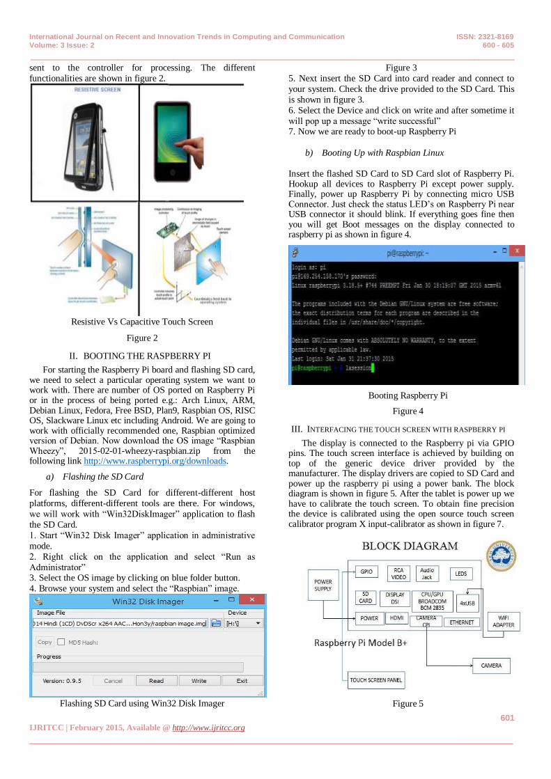
B. TOUCHSCREEN
Resistive touchscreens are touch-sensitive computer
displays composed of two flexible sheets coated with a
resistive material and separated by an air gap or microdots.
There are two different types of metallic layers. The first
type is called Matrix, in which striped electrodes on
substrates such as glass or plastic face each other. The second type is called Analogue which consists of transparent
electrodes without any patterning facing each other.
Resistive touchscreens typically have high resolution,
providing accurate touch control. Because the touchscreen
responds to pressure on its surface, contact can be made
with a finger or any other pointing device.
A capacitive touch screen panel consists of an insulator such
as glass, coated with a transparent conductor such as indium
tin oxide (ITO). As the human body is also an electrical
conductor, touching the surface of the screen results in a
distortion of the screen's electrostatic field, measurable as a change in capacitance. Different technologies may be used
to determine the location of the touch. The location is then
International Journal on Recent and Innovation Trends in Computing and Communication ISSN: 2321-8169 Volume: 3 Issue: 2 600 - 605
_______________________________________________________________________________________________
601 IJRITCC | February 2015, Available @ http://www.ijritcc.org
_______________________________________________________________________________________
sent to the controller for processing. The different
functionalities are shown in figure 2.
Resistive Vs Capacitive Touch Screen
Figure 2
II. BOOTING THE RASPBERRY PI
For starting the Raspberry Pi board and flashing SD card, we need to select a particular operating system we want to work with. There are number of OS ported on Raspberry Pi or in the process of being ported e.g.: Arch Linux, ARM, Debian Linux, Fedora, Free BSD, Plan9, Raspbian OS, RISC OS, Slackware Linux etc including Android. We are going to work with officially recommended one, Raspbian optimized version of Debian. Now download the OS image “Raspbian Wheezy”, 2015-02-01-wheezy-raspbian.zip from the following link http://www.raspberrypi.org/downloads.
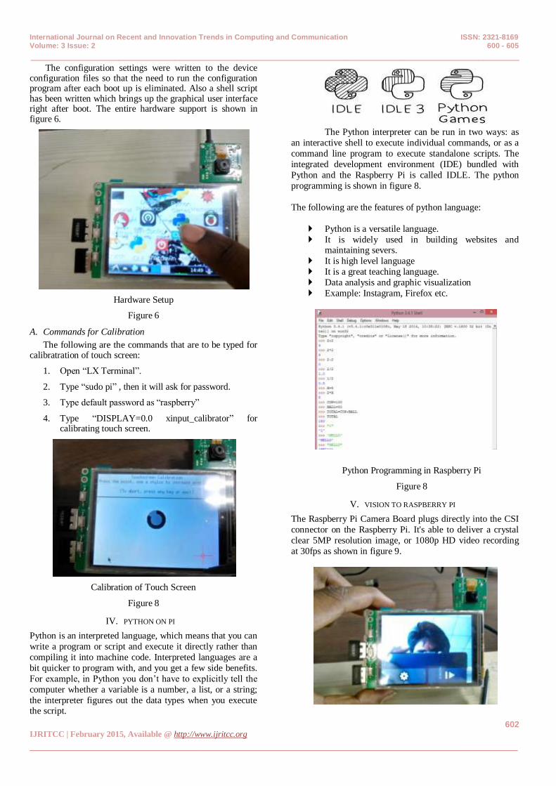
a) Flashing the SD Card
For flashing the SD Card for different-different host
platforms, different-different tools are there. For windows,
we will work with “Win32DiskImager” application to flash
the SD Card.
1. Start “Win32 Disk Imager” application in administrative
mode.
2. Right click on the application and select “Run as
Administrator” 3. Select the OS image by clicking on blue folder button.
4. Browse your system and select the “Raspbian” image.
Flashing SD Card using Win32 Disk Imager
Figure 3
5. Next insert the SD Card into card reader and connect to
your system. Check the drive provided to the SD Card. This
is shown in figure 3.
6. Select the Device and click on write and after sometime it
will pop up a message “write successful” 7. Now we are ready to boot-up Raspberry Pi
b) Booting Up with Raspbian Linux
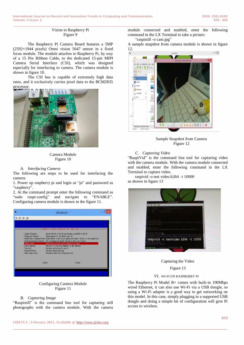
Insert the flashed SD Card to SD Card slot of Raspberry Pi. Hookup all devices to Raspberry Pi except power supply. Finally, power up Raspberry Pi by connecting micro USB Connector. Just check the status LED’s on Raspberry Pi near USB connector it should blink. If everything goes fine then you will get Boot messages on the display connected to raspberry pi as shown in figure 4.
Booting Raspberry Pi
Figure 4
III. INTERFACING THE TOUCH SCREEN WITH RASPBERRY PI
The display is connected to the Raspberry pi via GPIO pins. The touch screen interface is achieved by building on top of the generic device driver provided by the manufacturer. The display drivers are copied to SD Card and power up the raspberry pi using a power bank. The block diagram is shown in figure 5. After the tablet is power up we have to calibrate the touch screen. To obtain fine precision the device is calibrated using the open source touch screen calibrator program X input-calibrator as shown in figure 7.
Figure 5
International Journal on Recent and Innovation Trends in Computing and Communication ISSN: 2321-8169 Volume: 3 Issue: 2 600 - 605
_______________________________________________________________________________________________
602 IJRITCC | February 2015, Available @ http://www.ijritcc.org
_______________________________________________________________________________________
The configuration settings were written to the device configuration files so that the need to run the configuration program after each boot up is eliminated. Also a shell script has been written which brings up the graphical user interface right after boot. The entire hardware support is shown in figure 6.
Hardware Setup
Figure 6
A. Commands for Calibration
The following are the commands that are to be typed for calibratration of touch screen:
1. Open “LX Terminal”.
2. Type “sudo pi” , then it will ask for password.
3. Type default password as “raspberry”
4. Type “DISPLAY=0.0 xinput_calibrator” for calibrating touch screen.
Calibration of Touch Screen
Figure 8
IV. PYTHON ON PI
Python is an interpreted language, which means that you can
write a program or script and execute it directly rather than
compiling it into machine code. Interpreted languages are a
bit quicker to program with, and you get a few side benefits.
For example, in Python you don’t have to explicitly tell the
computer whether a variable is a number, a list, or a string;
the interpreter figures out the data types when you execute the script.
The Python interpreter can be run in two ways: as
an interactive shell to execute individual commands, or as a
command line program to execute standalone scripts. The
integrated development environment (IDE) bundled with
Python and the Raspberry Pi is called IDLE. The python
programming is shown in figure 8.
The following are the features of python language:
Python is a versatile language.
It is widely used in building websites and maintaining severs.
It is high level language
It is a great teaching language.
Data analysis and graphic visualization
Example: Instagram, Firefox etc.
Python Programming in Raspberry Pi
Figure 8
V. VISION TO RASPBERRY PI
The Raspberry Pi Camera Board plugs directly into the CSI
connector on the Raspberry Pi. It's able to deliver a crystal
clear 5MP resolution image, or 1080p HD video recording
at 30fps as shown in figure 9.
International Journal on Recent and Innovation Trends in Computing and Communication ISSN: 2321-8169 Volume: 3 Issue: 2 600 - 605
_______________________________________________________________________________________________
603 IJRITCC | February 2015, Available @ http://www.ijritcc.org
_______________________________________________________________________________________
Vision to Raspberry Pi
Figure 9
The Raspberry Pi Camera Board features a 5MP
(2592×1944 pixels) Omni vision 5647 sensor in a fixed
focus module. The module attaches to Raspberry Pi, by way of a 15 Pin Ribbon Cable, to the dedicated 15-pin MIPI
Camera Serial Interface (CSI), which was designed
especially for interfacing to camera. The camera module is
shown in figure 10.
The CSI bus is capable of extremely high data
rates, and it exclusively carries pixel data to the BCM2835
processor.
Camera Module Figure 10
A. Interfacing Camera
The following are steps to be used for interfacing the
camera:
1. Power up raspberry pi and login as “pi" and password as
“raspberry”.
2. At the command prompt enter the following command as
“sudo raspi-config” and navigate to “ENABLE”.
Configuring camera module is shown in the figure 11.
Configuring Camera Module
Figure 11
B. Capturing Image
“Raspistill” is the command line tool for capturing still
photographs with the camera module. With the camera
module connected and enabled, enter the following
command in the LX Terminal to take a picture:
“raspistill -o cam.jpg”
A sample snapshot from camera module is shown in figure
12.
Sample Snapshot from Camera
Figure 12
C. Capturing Video
“RaspiVid” is the command line tool for capturing video
with the camera module. With the camera module connected
and enabled, enter the following command in the LX
Terminal to capture video.
raspivid -o test video.h264 –t 10000 as shown in figure 13
Capturing the Video
Figure 13
VI. WI-FI ON RASPBERRY PI
The Raspberry Pi Model B+ comes with built-in 100Mbps
wired Ethernet, it can also use Wi-Fi via a USB dongle, so using a Wi-Fi adapter is a good way to get networking on
this model. In this case, simply plugging in a supported USB
dongle and doing a simple bit of configuration will give Pi
access to wireless.
International Journal on Recent and Innovation Trends in Computing and Communication ISSN: 2321-8169 Volume: 3 Issue: 2 600 - 605
_______________________________________________________________________________________________
604 IJRITCC | February 2015, Available @ http://www.ijritcc.org
_______________________________________________________________________________________
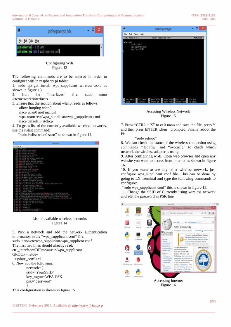
Configuring Wifi
Figure 13
The following commands are to be entered in order to
configure wifi in raspberry pi tablet:
1. sudo apt-get install wpa_supplicant wireless-tools as
shown in figure 13.
2. Edit the “interfaces” file: sudo nano
/etc/network/interfaces 3. Ensure that the section about wlan0 reads as follows:
allow-hotplug wlan0
iface wlan0 inet manual
wpa-roam /etc/wpa_supplicant/wpa_supplicant.conf
iface default inetdhcp
4. To get a list of the currently available wireless networks,
use the iwlist command:
“sudo iwlist wlan0 scan” as shown in figure 14.
List of available wireless networks
Figure 14
5. Pick a network and add the network authentication information in the “wpa_supplicant.conf” file:
sudo nano/etc/wpa_supplicant/wpa_supplicnt.conf
The first two lines should already read:
ctrl_interface=DIR=/var/run/wpa_supplicant
GROUP=netdev
update_config=1
6. Now add the following:
network={
ssid="YourSSID"
key_mgmt=WPA-PSK
psk="password"
} This configuration is shown in figure 15.
Accesing Wireless Network
Figure 15
7. Press “CTRL + X” to exit nano and save the file, press Y
and then press ENTER when prompted. Finally reboot the
Pi:
“sudo reboot” 8. We can check the status of the wireless connection using
commands “ifconfig” and “iwconfig” to check which
network the wireless adapter is using.
9. After configuring wi-fi. Open web browser and open any
website you want to access from internet as shown in figure
16.
10. If you want to use any other wireless network, just
configure wpa_supplicant conf file. This can be done by
going to LX Terminal and type the following commands to
configure:
“sudo wpa_supplicant conf” this is shown in figure 15.
11. Change the SSID of Currently using wireless network and edit the password in PSK line.
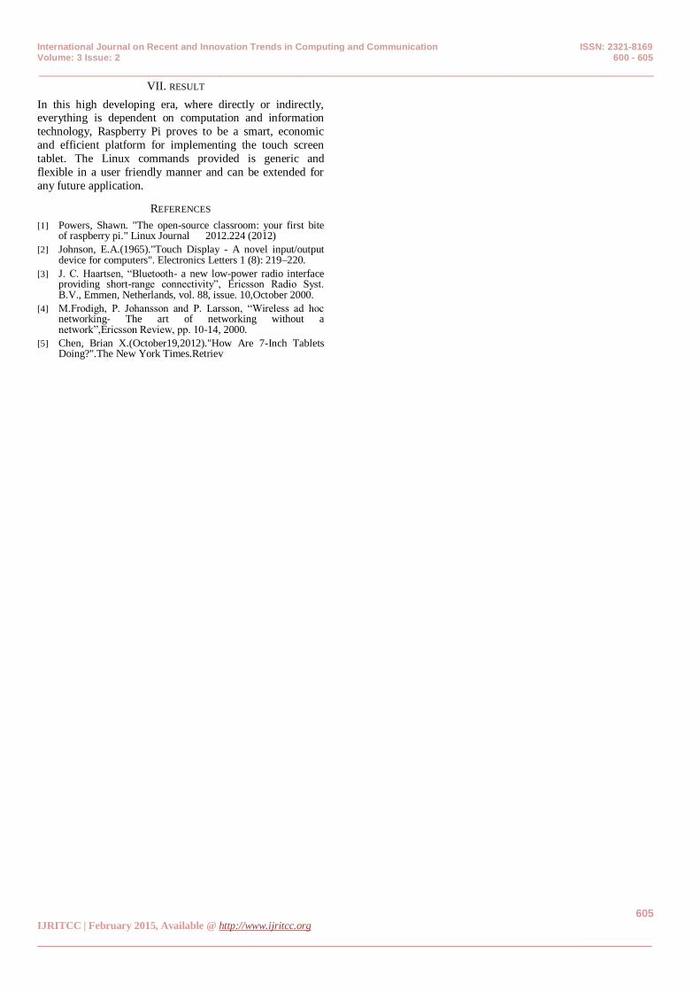
Accessing Internet
Figure 16
International Journal on Recent and Innovation Trends in Computing and Communication ISSN: 2321-8169 Volume: 3 Issue: 2 600 - 605
_______________________________________________________________________________________________
605 IJRITCC | February 2015, Available @ http://www.ijritcc.org
_______________________________________________________________________________________
VII. RESULT
In this high developing era, where directly or indirectly, everything is dependent on computation and information
technology, Raspberry Pi proves to be a smart, economic
and efficient platform for implementing the touch screen
tablet. The Linux commands provided is generic and
flexible in a user friendly manner and can be extended for
any future application.
REFERENCES
[1] Powers, Shawn. "The open-source classroom: your first bite of raspberry pi." Linux Journal 2012.224 (2012)
[2] Johnson, E.A.(1965)."Touch Display - A novel input/output device for computers". Electronics Letters 1 (8): 219–220.
[3] J. C. Haartsen, “Bluetooth- a new low-power radio interface providing short-range connectivity”, Ericsson Radio Syst. B.V., Emmen, Netherlands, vol. 88, issue. 10,October 2000.
[4] M.Frodigh, P. Johansson and P. Larsson, “Wireless ad hoc networking- The art of networking without a network”,Ericsson Review, pp. 10-14, 2000.
[5] Chen, Brian X.(October19,2012)."How Are 7-Inch Tablets Doing?".The New York Times.Retriev