rapid prototyping of control systems … systems from electromagnetic transient simulator program...
TRANSCRIPT
NSERC Industrial Research Chair in Power Systems Simulation EPEC 2011
RAPID PROTOTYPING OF CONTROL SYSTEMS FROM
ELECTROMAGNETIC TRANSIENT SIMULATOR
PROGRAM By:
Dexter M. T. J. Williams, Esa Nummijoki, Aniruddha M. Gole and Erwin Dirks
University Of Manitoba

EPEC 2011
Content • Introduction • Background • PSCAD Code Generator (PSCADCG) • Example System • Validation Testing • Conclusion

EPEC 2011
INTRODUCTION

EPEC 2011
Introduction • Software based design in power systems
– Grown in popularity with computer processing power
- Electromagnetic Transient (EMT) simulation models the network in the greatest detail
- Application: Flexible Alternating Current Transmission System (FACTS), High Voltage Direct Current (HVDC)
- Exhaustive simulations are done to confirm the controls operate in an appropriate manner
- However the control model must still be transferred into a useable control code for in-field use
EPEC 2011
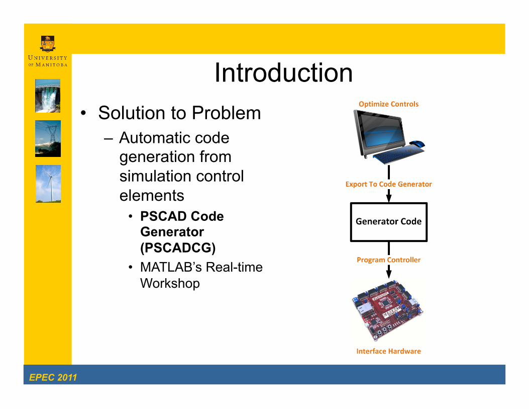
Introduction • Solution to Problem
– Automatic code generation from simulation control elements
• PSCAD Code Generator (PSCADCG)
• MATLAB’s Real-time Workshop

EPEC 2011
BACKGROUND

EPEC 2011
Background
Workspace Library

EPEC 2011
Background • PSCAD/EMTDC power system simulator
– 2 main types of Library components: – Electrical
» passive electrical components, power electronic components, machines, transformers, application specific components (EX: HVDC, FACTS)
– Control » arithmetic operations, logical operations, filters,
application specific controls and more
– Problem: To convert the control model to a real-world real-time implementation

EPEC 2011
Background • To allow for prototyping of the controls
the PSCAD Code Generator (PSCADCG) is used – PSCADCG reads the graphic model and
develops embedded software compatible code from the model

EPEC 2011
PSCAD CODE GENERATOR (PSCADCG)

EPEC 2011
PSCADCG • The PSCADCG contains 3 main parts involved in the rapid prototyping
process – Network generation – C function generation – C interface generation

EPEC 2011
PSCADCG: Network Generation • Network generation
– Generates a virtual network describing the interconnection of the control elements of the design
• Reads project and library files to generate and equivalent virtual network of the systems controls

EPEC 2011
PSCADCG:C Function Generation • C function generation
– Generates the code that describes the control operations modeled • Sequential orders all elements into a queue based on order of operation • Elements are sequentially de-queued and the code for each element is sequentially
generated • Then the code is formatted and used to generate the header and C file

EPEC 2011
PSCADCG: C Interface Generator • C interface
Generator – Interfaces the C
function to the hardware platform
• A hardware platform must first be selected
• The program reads the virtual header file and generates header, configuration and main loop C files

EPEC 2011
PSCADCG: C Interface Generator • C interface
Generator – Main program
• Configuring all parameters
• Infinite loop – Reads the A/D
converter values and runs
– Runs the C function generated by the C function generator
– Outputs the values to the ports

EPEC 2011
EXAMPLE SYSTEM

EPEC 2011
Example System • Step Down converter
– Reduces voltage from input to output using pulse width modulation – Parameters
• Input = 10 Volts • Output = 5 Volts • Voltage Ripple = 0.2% • Current Ripple = 2.0%

EPEC 2011
Example System: Controls • Step Down converter
– Control • Pulse Width Modulation • Negative feedback • Proportional-Integral (PI) controller for error reduction

EPEC 2011
Example System:PSCAD Simulation • Step Down converter
– Control system – Optimized controls
• Controls must be converted to a real time controller

EPEC 2011
Real-time Control Implementation • Cerebot 32MX4
development board – PIC32MX460F512L
microprocessor • 80 MHz • 32-bit memory. • PWM • digital and analog I/O
(Input and outputs) – 8 peripheral ports
• open collector driver • A/D • D/A converters • Etc.
– Programmed with C using the MPLAB development

EPEC 2011
VALIDATION TESTING

EPEC 2011
Validation Testing • 5 volt output test
– Calculated: 5.00 – Simulated: 5.00
• Blue signal represents the PWM signal (Top)
• Green signal represents PI control signal (Top)
• Blue signal represents the output voltages (Bottom)
• Green signal represents the input voltages (Bottom)
– Hardware: 5.10 • Blue signal represents the
PWM signal • Green signal represents
the input voltages • Orange signal represents
the output voltages

EPEC 2011
Validation Testing • 9.90 volt output test
– Calculated: 9.90 – Simulated: 9.90
• Blue signal represents the PWM signal (Top)
• Green signal represents PI control signal (Top)
• Blue signal represents the output voltages (Bottom)
• Green signal represents the input voltages (Bottom)
– Hardware: 9.53 • Blue signal represents the
PWM signal • Green signal represents
the input voltages • Orange signal represents
the output voltages

EPEC 2011
Validation Testing Duty Cycle (%)
Calc. (V)
PSCAD (V)
Actual Hardware
(V)
Error PSCAD
VS Hardware
(%) 1 50 5.00 5.00 5.10 1.00
2 99 9.90 9.90 9.53 3.70

EPEC 2011
CONCLUSION

EPEC 2011
Conclusion • PSCADCG capable of:
– generating control systems for a PSCAD system – generating most any control system generated by PSCAD
• PSCADCG can possibly reduce cost and expedite the development of controls
• Proof of Concept was demonstrated using a simple step-down controller – It is equally applicable to design arbitrary Power System
Controllers – Larger scale / power systems may require additional hardware
for isolation, etc. • Additional code may be needed to interface with these devices
• Future work – Support for multiple page modules – Support for FPGA platforms

EPEC 2011
QUESTIONS