rapid processing of synthetic seismograms using windows azure...
TRANSCRIPT

Rapid Processing of Synthetic Seismograms using Windows Azure
CloudVedaprakash Subramanian, Liqiang Wang
Department of Computer ScienceUniversity of Wyoming
En-Jui Lee, Po ChenDepartment of Geology and Geophysics
University of Wyoming
1

• Scientific applications
– Large amount of computing resources
– Massive storage for datasets
• Traditionally Handled by HPC Clusters
– But Cost-ineffective
• Claim: Cloud Computing is a better substitute
2
Introduction

• Conduct numerical simulation of synthetic seismograms
• Implemented a system on Azure cloud
– to generate synthetic seismograms on the fly based on user queries
– to deliver them in real-time
3
… more

• Seismogram is a record of the ground shaking
• Synthetic seismograms are generated by solving seismic wave – equation
• Method is rapid centroid moment tensor (CMT) inversion method
– Based on 3D velocity model
• To increase efficiency, we store Receiver Green Tensors strain fields
– Generated at the receiver’s location
4
Synthetic Seismograms

• The input parameters for this wave-equation are
– latitude, longitude and depth of the earthquake locations
– strike, dip, and rake (source parameters)
5
… more
… more
• Helps to map the Earth’s internal structure
• Locate and measure the size of different seismic sources
• For realistic interpretation of structures
• Seismic Hazard Analysis
Why synthetic seismograms is
important?
6

Windows Azure
7

8
• Windows Azure is Platform as a service architecture
• Provides
– Scalable cloud operating system
– Data storage system
• User controls the hosted application
• User cannot control the underlying infrastructure
Windows Azure

• Azure service consists of :
– Web role
• For web application
• For user interface
– Worker role
• For generalized development
• For background processing
• Roles are virtual machines
• Say, 2 instances of worker role = 2 virtual machines running the code of worker role
Service Architecture

• Blobs
• Tables
• Queues
• Drives
• Our system uses only first three
Storage Abstractions

• Blobs
– Interface for storing files
– Two types namely Page blobs and Block blobs
– Containers for grouping
BlobContainerAccount
Geo
CaliforniaFile1 txt
File2 txt
Texas File1 txt
Blob Storage

• Tables
– Structured storage– Consists set of entities, which contain a set of
properties– Partition key and Row key
EntityTableAccount
Geo
Customers
Name = … Email = … Name = … Email = …
PhotosPhoto Id = …
Date = …
Table Storage

• Queues
– Reliable storage and delivery of messages
– Communication between roles
MessageQueueAccount
Geo OrdersID = ……
ID = …
Queue Storage

• Azure master system
– Automatically load balance based on the partition key
• Partition key for various storage abstractions
– Blobs – Container Name + Blob Name
– Entities – Table Name + Partition Key
– Messages – Queue Name
14
Load Balancing

Implementation of the System
15

• The architecture of the system :– Web Role
• User interface
– Job Manager• Coordinate the computation
• Monitor the system
Use
r
Request Queue
ComputationInput Queue
Windows Azure Storage (Blob, Table, Queue)
ComputationOutput Queue
Overview of the System

– Computation Worker Role
• Computation stuff
– 3 Azure Queues
• Communication interface between the roles
Use
r
Request Queue
ComputationInput Queue
Windows Azure Storage (Blob, Table, Queue)
ComputationOutput Queue
… more
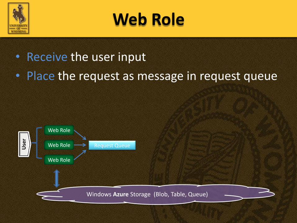
• Receive the user input
• Place the request as message in request queue
Web RoleU
ser
Request Queue
Windows Azure Storage (Blob, Table, Queue)
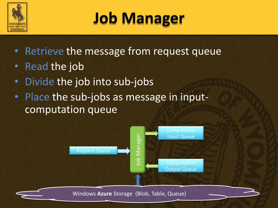
• Retrieve the message from request queue
• Read the job
• Divide the job into sub-jobs
• Place the sub-jobs as message in input-computation queue
Job Manager
Windows Azure Storage (Blob, Table, Queue)
Request Queue
ComputationInput Queue
ComputationOutput Queue

• Num of computation worker roles : 5
• Num of CPU cores in each instance : 8
• Input : 1000 source locations
• Num of queue messages : 1000 / 8 = 125
• 125 queue messages served by 5 computation worker roles
• Performance gain factor (Theoretical)
= Num of CPU cores * Num of instances = 8 * 5 = 40
Coordinate the Computation
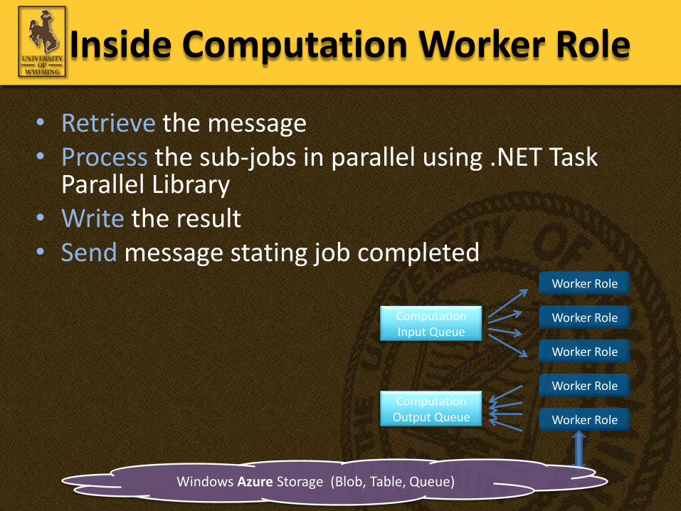
• Retrieve the message • Process the sub-jobs in parallel using .NET Task
Parallel Library• Write the result • Send message stating job completed
Inside Computation Worker Role
Windows Azure Storage (Blob, Table, Queue)
ComputationInput Queue
ComputationOutput Queue

• Based on the response time of the message
• Threshold response time is 2ms
• If exceeds
– Allocate a new instance of computational worker role
– Maintain its detail
Monitor System Response

• De-allocate if
– any new instance has been allocated
– and its lifetime > one hour
– and no message in the queue
… more

Distributed File System
Computation Input Queuemsgmsgmsgmsgmsg
Request to allocate VM
Monitor System Response

• Allocation & de-allocation are asynchronous
• So, mutual exclusion lock are enforced between
– Job assignment
– De-allocation of an instance
Job Manager

• Seismic wave observations stored as data file
• Each data file is represented by its own latitude and longitude
• So, blob name = latitude + longitude
• For grouping the blobs, the region of California is divided into blocks– based on the seismic wave observation
stations
Point (40’59’’N, 122’7’’W)
4059-1227
26
Data Storage

• Currently 4096 stations = 4096 blocks
• Each block is characterized by range of latitude and longitude
• So, block identification number = range of latitude + longitude
• Container name = identification number
3525-3451-1193-11647
34’51’’N, 116’47’’W
35’25’’N, 116’47’’W
34’51’’N, 119’3’’W
35’25’’N, 119’3’’W
27
… more

• Divide California region into 16 parts
• 1 Table for 1 part
• Store list of blocks in the part into the table
• Helps in better retrieval 28
… more

• Locate blob corresponding to the given point
– Retrieve the container name and blob name
• Retrieve container name from the table – Locate the table
– Do a linear search inside the table
• Blob name = latitude + longitude
29
Data Query Algorithm

Point
41’43’’N, 124’6’’W 41’43’’N, 120’43’’W
39’11’’N, 120’43’’W39’11’’N, 124’6’’W
40’27’’N, 124’6’’W
39’11’’N, 122’52’’W
40’27’’N, 122’52’’W40’27’’N, 123’56’’W
40’85’’N, 122’52’’W
40’85’’N, 123’56’’W
40’59’’N, 122’7’’W
30
Data Query Algorithm

Experiment
31

• Performance was evaluated on
– various configurations and number of instances of computational worker role
– datasets from different number of seismic wave observation
32
Experiment
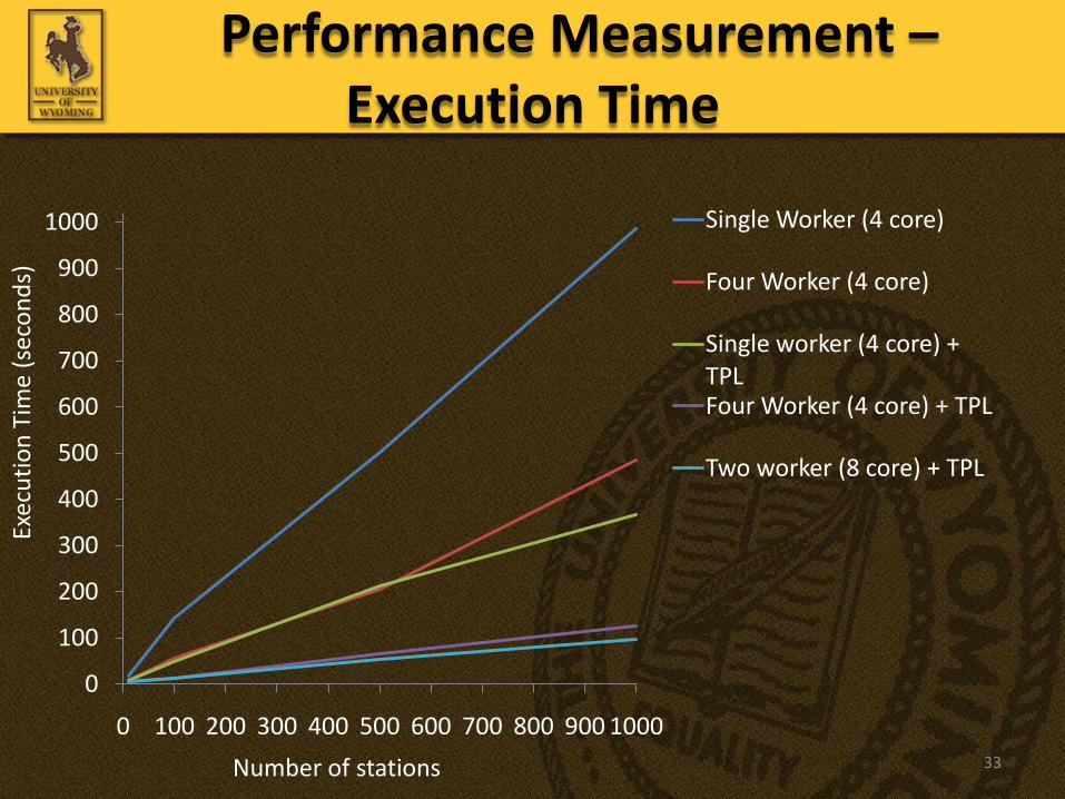
0
100
200
300
400
500
600
700
800
900
1000
0 100 200 300 400 500 600 700 800 900 1000
Single Worker (4 core)
Four Worker (4 core)
Single worker (4 core) + TPLFour Worker (4 core) + TPL
Two worker (8 core) + TPL
Number of stations
Exec
uti
on
Tim
e (s
eco
nd
s)
33
Performance Measurement –Execution Time

Conclusion
34

• Implemented the system on Windows Azure
• Hence Cloud is a better substitute
• Future Work :
– Add Seismic Hazard Analysis feature to the system
35
Conclusion

Thanks
36