rapid backup power solution guide with stabiliti pcs · 2017-12-04 · ieee 1547.4 – 2011 ansi...
TRANSCRIPT

Page 1 of 17DOC-00030 Rev A © Copyright 2017 by Ideal Power Inc. All rights reserved.
Application Note 504
Rapid Backup Power Solution Guide with Stabiliti PCS
1.0 PURPOSE AND SCOPE
The Stabiliti™ series are 30 kW bi-directional Power Conversion Systems (PCS) for commercial 3-phase electricity applications. The Stabiliti may be purchased with either one DC port (30C: for use with battery) or two DC ports (30C3: battery and PV).
When used in standalone microgrid (voltage-forming) applications, the Stabiliti’s AC1 power port will form a 3-phase AC output at 480 Vac and 60 Hz supporting real, as well as reactive microgrid loads up to their nominal nameplate ratings of 30 kW and 27 kVAR.
In voltage-following applications, the AC1 port will source or sink power into a utility interconnection, with the same AC characteristics as described above.
Contact Ideal Power technical support [email protected] regarding applications operating at voltages other than the default 480 Vac and 60 Hz noted above.
Supporting both voltage-following and voltage-forming modes of operation at a customer facility delivers greater value than traditional grid-tied only systems. Typically, the Stabiliti operates in voltage-following mode, sourcing or sinking power to and from the grid, utilizing PV and a battery as its DC energy sources. If/when the grid fails, the Stabiliti rapidly re-configures itself to voltage-forming mode, enabling backup support of facility critical loads.
This application note is an advanced solution guide for a Battery Energy Storage System (BESS or ESS) supporting rapid transition to backup power by using the Ideal Power Stabiliti 30C or 30C3 PCS with an external utility interconnection relay. The document provides recommendations for designing control hardware and software systems along with applicable operational logic. This application note assumes a basic understanding of the components and functions of an ESS and backup power system. For introductions to an ESS or backup power please refer to the following Ideal Power application notes:
App Note 601: Energy Storage Systems Utilizing the Stabiliti PCS App Note 503: Rapid Backup Power Utilizing the Stabiliti PCS
Other applicable Application Notes for microgrids and backup power include:
App Note 102: Interconnection and Transformers
Ideal Power highly recommends engaging a utility interconnection representative as early as possible
in the process of designing a project involving an electrical island for backup power to determine

Page 2 of 17DOC-00030 Rev A © Copyright 2017 by Ideal Power Inc. All rights reserved.
local utility interconnection requirements as an Authority Having Jurisdiction. This Application Note is provided as-is with no warrants that the system described herein will be approved by a utility. The actual transfer time to back-up power may be dependent on utility interconnection requirements. Ideal Power is not responsible for design and implementation of hardware, control, or safety systems outside of its Stabiliti PCS.
CONTENTS
Rapid Backup Power Solution Guide with Stabiliti PCS ......................................................................................... 11.0 Purpose and Scope ................................................................................................................................................... 12.0 Safety .......................................................................................................................................................................... 23.0 Terms and Definitions ................................................................................................................................................ 34.0 Applicable Standards ................................................................................................................................................ 35.0 Stabiliti Backup Capabilities .................................................................................................................................... 36.0 System Layout and Components ............................................................................................................................. 47.0 Operational Sequence .............................................................................................................................................. 58.0 System Design Features and Options .................................................................................................................... 59.0 Electrical Connections & Signaling ........................................................................................................................ 810.0 Equipment Coordination for Islanding Transitions ............................................................................................. 911.0 Interconnection Control System Operation ....................................................................................................... 1112.0 PCS Operation ........................................................................................................................................................ 12
Software Configuration and Control ............................................................................................................... 12PCS FPWR States .............................................................................................................................................. 13Electrical Signaling for Transfers .................................................................................................................... 14Transfer States ................................................................................................................................................... 14Electrical Signaling for Synchronous Starts ................................................................................................. 15PCS Status Feedback ........................................................................................................................................ 15PCS Commissioning Requirements ................................................................................................................. 16
13.0 SEL-547 Sample Configuration............................................................................................................................. 16Additional Questions? ................................................................................................................................................... 17Disclaimers and Intellectual Property Notice ........................................................................................................... 17
2.0 SAFETY
This application note should be used in conjunction with other product and safety documentation provided by Ideal Power. The intended audience is engineering and lab personnel familiar with high-voltage/high-power systems and the general safety considerations related to the wiring and use of 3-phase AC electricity, battery systems, and PV energy sources.
Additionally, this document does not purport to make recommendations regarding conformance with applicable electrical codes. A qualified electrical engineer should be engaged to do detailed system design and ensure conformance with applicable codes. Refer to the product datasheet for detailed specifications upon which to base any detailed designs. Lastly, this document assumes that the reader is already familiar with the Stabiliti Modbus interface, and is comfortable using that interface to configure, monitor and command PCS operation.

Page 3 of 17DOC-00030 Rev A © Copyright 2017 by Ideal Power Inc. All rights reserved.
3.0 TERMS AND DEFINITIONS
Power Conversion System (PCS) – a name for the class of power electronics hardware that converts back and forth between AC power and DC power, alternately referred to as a bi-directional converter. The term PCS is used throughout this document in reference to the Stabiliti 30C and 30C3 due to the subject matter focus on bi-directional battery support capabilities.
Rapid Transfer – PCS transitions from grid following to grid forming or voltage following to voltage forming that occur within a few cycles of the fundamental grid frequency. This results in the line voltage not dropping and lighting not losing power therefore it is also sometimes referred to as a blinkless transition. However, the actual transfer time varies and may result in a brief power outage or blink depending on the interconnection switchgear and/or utility interconnect requirements.
Grid-Following – PCS output voltage follows an existing grid source (usually utility grid or a generator) and acts as a current source or sink. Also referred to as voltage-following.
Grid-Forming – PCS regulates its output voltage operating as a grid source that loads can draw from. Also referred to as voltage-forming.
Area EPS – Electrical power system outside the bounds of the facility, typically the local electric utility distribution network
Facility EPS – Electrical power system within the bounds of the facility
Electrical Island – An isolated electrical system, alternatively a microgrid, typically includes localized power generation and loads.
4.0 APPLICABLE STANDARDS
IEEE 1547 – 2003
IEEE 1547.4 – 2011
ANSI C84.1
UL 1741SA
Local utility regulations and interconnection standards such as Rule 21 in California
5.0 STABILITI BACKUP CAPABILITIES
• For a complete list of capabilities please refer to Data Sheet DAT-00018 Stabiliti™ Series Microgrid Specifications Supplement.
• Once installed with appropriate external islanding hardware and controls detailed later in this document, the Stabiliti will move rapidly from grid-following to grid-forming modes without need for intervention by an external site controller.
• The transitions described in this Application Note can be performed with multiple Stabiliti PCS in parallel enabling support of a facility grid >30 kW. Contact Ideal Power for special considerations

Page 4 of 17DOC-00030 Rev A © Copyright 2017 by Ideal Power Inc. All rights reserved.
Figure 1: Backup Power ESS Topology with Stabiliti PCS
when paralleling the Stabiliti PCS.• The transition to backup power with a Stabiliti is not an uninterruptable power supply and should
not be depended upon to support highly sensitive equipment. The system described herein does not conform with UL 1778 (Uninterruptible Power Systems).
• While in grid-following or grid-forming mode, the Stabiliti utilizes a 3-wire delta output: all power is transferred phase leg to phase leg when exporting, or importing power to/from the grid.
• The Stabiliti can operate at 480 Vac or 380 Vac and 60 Hz or 50 Hz to support many international grid standards. Supporting other grid interconnection voltages, such as 208 Vac or 600 Vac requires an external transformer.
• The Stabiliti must have appropriate and sufficient battery energy storage to enable voltage-forming mode and to support priority loads. PV-only based microgrids are not supported.
6.0 SYSTEM LAYOUT AND COMPONENTS
A backup power system is typically comprised of nine (9) primary elements as shown in Figure 1. Note this conceptual schematic neglects standard circuit safety devices such as AC or DC disconnects. An electrical engineer should be engaged to do the detailed system design and ensure conformance with applicable electrical and safety codes.
1. Primary utility grid2. Utility line isolation contactor (Grid Interface Contactor or GIC)3. Utility interconnect relay (ex. SEL-547)4. Uninterruptible power supply (UPS)5. Priority loads electrical panel6. Ideal Power Stabiliti PCS (30C3 model shown with second DC port)7. Battery System8. PV Array9. System Site Controller
Blue lines indicate software communicationDotted lines indicate hardware control or sensing

Page 5 of 17DOC-00030 Rev A © Copyright 2017 by Ideal Power Inc. All rights reserved.
7.0 OPERATIONAL SEQUENCE
The following is an abstracted summary of the events in a transition away from the utility grid source to the ESS as a grid source and then back.
Loss of Utility Grid1. The PCS should be pre-configured with AC1 port as FPWR (Facility Power) and the DC2 battery
port as NET. The 30C3’s DC3 port provides an optional input for a PV Array.2. The utility voltage or frequency goes out of acceptable range.3. The interconnection relay senses this excursion and triggers the contactor to open.4. The contactor and PCS receive a mirrored low voltage control signal from the relay. As the
contactor opens, the PCS transitions to grid forming mode.5. The site system controller may poll the interconnection relay and PCS to register the grid and
system state.6. The load will be automatically supported and will draw down on the battery energy
Off-grid Backup Operation• The PV tied to port DC3 will contribute to supporting the priority loads and will charge the battery
whenever the available PV resource is greater than the loads. PV should be curtailed if the battery reaches its maximum state of charge (SoC).
• If the battery SoC reaches its minimum, the external system controller should disable the converter to protect the battery from damage. This will immediately drop support of all critical loads.
Return of Utility Grid1. At some time during backup power operation the utility grid returns.2. The interconnection relay waits the required 5 minutes ensuring the grid remains within range.
It then waits until the voltage, frequency and phase are synchronized on the facility and utility sides of the contactor. Upon synchronization, the interconnection relay triggers the contactor to close. Natural variations in the phase may result in a brief additional delay before this synchronization occurs.
3. The contactor and PCS receive a mirrored low voltage control signal. As the contactor closes, the PCS transitions to grid-following mode.
4. The PCS will resume grid-following operation and power transfer as it had been commanded prior to the grid outage.
8.0 SYSTEM DESIGN FEATURES AND OPTIONS
Implementation of a backup power project with the Stabiliti can include various system-level components and features which are discussed here.
Core Components
Utility Interconnect Relay – Utility interactive inverter systems must conform with anti-islanding rules as outlined in IEEE 1547 and UL 1741SA. This mandates that an inverter or PCS must not energize a dead utility Area EPS grid. For the Stabiliti to form a local grid at the level of the Facility EPS, the project designer must delegate the anti-islanding control responsibility to a separate device. The SEL-547 is a cost-effective solution for this situation although more advanced SEL devices may also be used. SEL is widely recognized as an industry leader and many utilities in the U.S. specify SEL products as their preferred relay solution. The SEL-547 also manages the synchronous reconnection and other optional features discussed below.

Page 6 of 17DOC-00030 Rev A © Copyright 2017 by Ideal Power Inc. All rights reserved.
The BE1-11i interconnection relay by Basler Electric is an alternate option, preferred over the SEL-547 in some jurisdictions. It is configured similarly to the SEL-547 as described in this Application Note.
System designers should inquire with their local utility to validate conformance of the SEL-547 or BE1-11i to local AHJ requirements. Ideal Power cannot guarantee either device will be accepted for interconnection by your local utility.
Grid Interface Contactor – This device works solely in response to the interconnection relay control to electrically isolate a portion of the local Facility EPS from the utility Area EPS, ensuring that energizing on the facility side does not present a safety risk to the utility side. The 3-pole AC contactor current rating should be consistent with the load type and rating of the backup system, nominally the nameplate PCS capacity.
Note that the opening and closing response time of the GIC will affect the grid-forming transition time independent of the PCS. Selecting a contactor with a rapid opening time is advised. Ideal Power has found that AC actuated coils tend to operate faster than low-voltage DC coils, however please refer to the manufacturer’s datasheet.
Uninterruptible Power Supply – The UPS shown is required and must be sized to ensure sustained power to the system controller, PCS, utility interconnection relay, and any other control power during the transition to and from grid-forming by the PCS. The UPS should be powered by the priority loads subpanel to ensure that its batteries remain charged during a backup power event. The Stabiliti PCS requires 150 W of UPS 24 Vdc power.
Critical Loads Subpanel – The critical loads to be supported by the PCS during grid-forming operation should be identified and their load profiles characterized by the end user and must never exceed the nominal 30 kW nameplate rating of the Stabiliti PCS. This distribution panel and the connected loads are isolated by the Grid Interface Contactor for the backup power island.
Transformer – The Stabiliti PCS has 3-phase delta connection, so it cannot natively support phase-to-neutral loads. Additionally, when the grid interface contactor opens, any ground anchoring of phase voltages that may have been handled by the utility service will be lost. The voltages at the PCS inputs must be therefore be constrained to a nominal 277 Vac phase to ground by an external transformer. Phase to neutral load support and phase-anchoring both require an external transformer. Refer to Application Note 102 for important information on using transformers with the Stabiliti PCS.
Optional Features
Ideal Power recommends implementation of the following features into the interconnection relay configuration and system design. The remainder of this Application Note assumes these features are present in the system.
Hardware Enable (On/Off) – The interconnection relay may be configured to accommodate a low-voltage hardware input signal that enables or disables the overall operation of the interconnect relay and contactor. It may function as an emergency stop input or other function desired by the system designer. This supersedes all other functions of the system. Note that the disabled or off state is the safe, deenergized state which corresponds with the contactor open toward the utility. To fully deenergize the entire ESS backup power system the same input signal may be paralleled with the emergency stop input on the Stabiliti PCS.

Page 7 of 17DOC-00030 Rev A © Copyright 2017 by Ideal Power Inc. All rights reserved.
Manual Override – Accommodates an input switch (electrical or software) that a user may toggle to open the contactor and transition to backup power islanding, and then toggle again to let it resynchronize and close to the energized grid. In the descriptions below this is referred to as the Island Only or Automatic toggle switch.
GIC Fault Detection – Compares the expected state of the GIC with its auxiliary contact feedback signal and outputs a fault signal if the two do not match, indicating a problem with the contactor.
Local Facility EPS Fault Detection – Monitors the health of the Facility EPS during islanding operation. If the island goes black (assumed to be due to a PCS failure) the relay will bypass the five (5) minute reconnect delay and connect to the utility grid immediately once it is determined to have returned and be minimally stable. Appropriate signals will be transmitted to the PCS to operate in grid-following mode.
Relay Faults – Built into the interconnection relay device, this provides fail-safe protection against problems with the device. Both hardware and software interlocks are included to open the contactor. Although not discussed in this Application Note, the relay hardware fault interlock could also be interlocked with an emergency stop input to the Stabiliti PCS.

Page 8 of 17DOC-00030 Rev A © Copyright 2017 by Ideal Power Inc. All rights reserved.
9.0 ELECTRICAL CONNECTIONS & SIGNALING
Solid lines represent high voltage wires. Dotted lines represent low voltage supply or signal wires. Note that some of the supply or control wires may alternately be 120 Vac depending on the choice of hardware.
The schematic shown in Figure 2 represents a simple installation of an ESS backup power islanding system. For simplicity, the priority loads subpanel has been omitted (refer to Figure 1). The electrical single line diagram presented focuses on the interconnection relay and its specific connection points along with the signaling between the GIC, PCS and system controller. It is expected that additional components and wiring such as potential transformers, terminal blocks and switches are required to build a complete system, the details of those components are beyond the scope of this document.
The key component to this system is the interconnection relay. In the sample system, the relay is programmed to monitor the area EPS side and facility EPS side of the GIC and actuate the GIC based on the observed conditions.
The PCS has two digital inputs which are used for a mirrored GIC command signal from the relay and the GIC acknowledge feedback signal from the GIC auxiliary contact. The PCS firmware processes these
Figure 2: Sample Stabiliti PCS, GIC & Interconnection Relay Single Line Diagram

Page 9 of 17DOC-00030 Rev A © Copyright 2017 by Ideal Power Inc. All rights reserved.
inputs and utilizes them for transition control between the grid-following and grid-forming states. The connections are as follows:
The GIC control coil is routed through one output contact of the relay. Such wiring allows the relay to control the open/closed state of the GIC by actuating its internal contact. The normally-open auxiliary contact of the GIC is also routed to the relay. The auxiliary contact acknowledges successful execution of the GIC command indicating that the GIC is functional and provides transfer confirmation to the PCS.
Note that the relay employs dry contacts therefore control voltages other than 24 Vdc (typically 120 Vac) are possible dependent on choice of GIC contactor and relay. Different contactors and control coil voltages provide different response times which may impact the overall system grid-forming transition times independent of the PCS.
10.0 EQUIPMENT COORDINATION FOR ISLANDING TRANSITIONS
One proposed islanding methodology transfers the site to islanded operation based on tight grid voltage and frequency limit trip settings to maximize system uptime at the risk of prematurely disconnecting from the Area EPS. To do this, the interconnection relay is configured to stay connected to the area EPS only for small deviations from nominal over-voltage and under-voltage (OV/UV) and over-frequency and under-frequency (OF/UF) trip settings and inside the ANSI C84.1 Range A voltage limits. Refer to Figure 4 curve A.
Once configured with tighter trip limits, the relay will transition to island operation during abnormal
Relay Signal PCS Input
GIC command mirror DI1 (ISLAND_COMMAND)
GIC acknowledge DI2 (ISLAND_ACKNOWLEDGE)
Figure 3: PCS control board connectionsincluding ISLAND_COMMAND & ISLAND_ACKNOWLEDGE

Page 10 of 17DOC-00030 Rev A © Copyright 2017 by Ideal Power Inc. All rights reserved.
area EPS conditions before the grid-following (tied to the area EPS) Stabiliti PCS trips offline due to the abnormal conditions consistent with UL1741SA and IEEE 1547. The early OV/UV and OF/UF detection provided by the relay configuration allows the PCS to transition to voltage forming mode before it would otherwise fault. Refer to Figure 4 curve A.
Integrating PV Inverters into the single-line shown in Figure 2 above results in a more complex islanding system. Due to inherent variability in different PV inverter anti-islanding mechanisms as well as uncertainty in the electrical dynamics in the transition period, Ideal Power cannot guarantee PV inverters will not trip offline during transitions to and from backup power mode. Contact Ideal Power technical support if you intend to integrate PV Inverters in your backup system design.
An alternate islanding use case transfers the site to islanded operation based on standard IEEE 1547 OV/UV and OF/UF trip settings. To do this, the interconnection relay is configured to stay connected to the area EPS while within the tolerances specified by IEEE 1547. Refer to Figure 4 curve C.
In this use case, the Stabiliti PCS’ factory default OV/UV and OF/UF trip settings must be relaxed to not trip offline at the same moment as the relay disconnects the facility from the grid. Refer to Figure 4 curve B.
The Stabiliti PCS grid-connect AC trip settings must not be changed without permission from your local utility. Please contact Ideal Power technical support for assistance in changing these settings if you are granted permission to do so.
Any PV inverters located downstream of the relay and GIC will likely trip nearly simultaneously to the relay and then wait the obligatory five (5) minutes before reconnecting to the grid formed by the Stabiliti PCS. In some cases, PV inverters may be reconfigured similar to the Stabiliti PCS with looser trip settings to avoid down-time. This should likewise be approved by the local utility as well as the PV inverter manufacturer.
In either case, the islanding methodology must be approved by the local utility as the Authority Having Jurisdiction on this issue. Ideal Power highly recommends engaging a utility interconnection representative as early as possible in the process of designing a project to determine local utility interconnection requirements.
Additional Notes:• Due to measurement processing and the finite time required for contacts to close and open,
the actual disconnection time from the area EPS by the GIC may be slightly longer than the configured relay timings by up to a few cycles.
• UL 1741SA is the next generation standard for utility interconnection of power converters and includes provisions for a variety of responses to abnormal grid conditions. These responses are specified by local or regional grid authorities such as with Rule 21 in California. The discussion above addresses the general and simple case of IEEE 1547 however the same logic would apply to applications where the PCS is configured according to Rule 21: the relay settings would be set tighter than the PCS settings.
When the utility grid returns the relay will first monitor the Area EPS that it remains within the acceptable nominal operating range for five (5) minutes. It will then validate that the Area EPS and Facility EPS voltage waveform comply with the criteria for synchronous interconnection consistent with IEEE 1547 whereby the voltages must be within 10%, frequencies within 0.3 Hz and phase angle within 20°. While the PCS will exhibit frequency and voltage droop in response to real and reactive power loading, it will hold the microgrid voltage within these boundaries during normal voltage forming operation. Due to slight frequency mismatches during the synchronism check, it may take a few seconds for the waveforms to

Page 11 of 17DOC-00030 Rev A © Copyright 2017 by Ideal Power Inc. All rights reserved.
align within the phase angle tolerance and satisfy the relay to then activate the transition to grid-following.
11.0 INTERCONNECTION CONTROL SYSTEM OPERATION
The interconnection control system consists of the utility interconnection relay and the GIC. The interconnection system is intended to be largely autonomous with user input commands for on/standby, commanded island only or emergency stop. The available outputs from the interconnection control system are GIC command, GIC acknowledge, local facility EPS fault, GIC fault and relay alarm/fault.
The GIC Fault and Local Fault are software control signals that can optionally be configured as hardware output signals. These seven (7) inputs/outputs are shown in Table 1 as a truth table to provide understanding of the overall operation of the interconnection control system. Refer to Figure 5 for the corresponding state diagram for the PCS. A system emergency stop may be electrically interlocked with the relay Alarm contact or relay power supply and the PCS emergency stop to fully deenergize and disable the backup power system.
Figure 4: Coordination of device grid-connect voltage trip settings (Frequency trip settings similar)

Page 12 of 17DOC-00030 Rev A © Copyright 2017 by Ideal Power Inc. All rights reserved.
Relay Inputs Relay Outputs PCS Action
On/Standby
Island Only/Automatic
GIC/Island Command
Island Acknowledge
Local Fault
GIC Fault
Relay Alarm
Standby - - No No No No PCS Standy
On Island Yes No No No NoTransition to Commanded
Island
On Island Yes Yes No No NoCommanded
Island
On Auto Yes No No No NoTransition to Autonomous
Island
On Auto Yes Yes No No NoAutonomous
Island
On Auto No Yes No No NoTransition to
Area EPS
On Auto No No No No No Area EPS
On Auto Yes Yes Yes No NoIsland Fault (PCS Fault)
- - - - - Yes -GIC Fault:
System Off
- - - - - - YesRelay Fault: System Off
The interconnection control system does provide for a GIC fault output and Relay fault output but does not use this fault internally for any of the transition criteria. The logic behind this is that the GIC fault indicates that the GIC itself or GIC control has malfunctioned; therefore relying on the same system to force a known system state isn’t safe. The result of this is that the interconnection control system outputs the GIC fault and relies on external human intervention to resolve the GIC fault. The GIC and Relay would be normally-open, fail-safe devices and expected to conform with applicable safety and performance standards which means in a faulted state they would default to an open, disconnected state.
12.0 PCS OPERATION
Software Configuration and ControlIn order to enable the rapid transfer capability of the Stabiliti PCS it must be configured for Facility Power (FPWR). While operating with this Control Method, the PCS will follow a grid voltage when present and thereby may be commanded by an external controller to charge or discharge kW or kVAR as in Grid Power (GPWR). When the grid is absent and the PCS is configured to FPWR and appropriate external islanding control signals are sensed, it will automatically and rapidly move to voltage forming to support critical loads.
Table 1: Interconnection Control System operational truth table

Page 13 of 17DOC-00030 Rev A © Copyright 2017 by Ideal Power Inc. All rights reserved.
The PCS should be configured as follows over its Modbus interface.
Register ID Register Name Value Setting
65 p1_control_method FPWR 0x0502
71 p1_voltage_setpt 480 Vac 480 (Default)
72 p1_frequency_setpt 60 Hz 60000 (Default)
During testing and commissioning of microgrid capabilities it is highly recommended that the Manual operating mode is used by leaving Modbus register 267 at the default value of 0. This then requires an operator or external system controller to send user_start or user_stop commands to enable the PCS via registers 263 and 264. For regular operation, it is also recommended that the Manual operating mode is employed so the external system controller can exert complete control over PCS transitions such as black starts which are discussed later in this guide. In Manual mode the PCS will still automatically perform rapid transfers to and from the Area EPS however it will not automatically attempt to recover after a fault therefore additional fault handling functionality would be necessary of the system controller. In some cases, the Automatic operating mode may be appropriate, please contact Ideal Power Support at [email protected] for assistance with your controls design.
CAUTION: Please use care before enabling the PCS in either operating mode while in FPWR and ensure the overall system is configured as specified. If not configured properly, unexpected behavior may occur including energizing the PCS 3-phase 480 Vac output which is dangerous to personnel and may damage the converter if done in the presence of a utility grid voltage.
PCS FPWR StatesThe FPWR Control Method includes a number of operating substates which are reached through particular sequencing of the Island Command and Island Acknowledge signaling as shown in Figure 5.
Table 2: PCS Modbus Configuration
Figure 5: FPWR State Diagram

Page 14 of 17DOC-00030 Rev A © Copyright 2017 by Ideal Power Inc. All rights reserved.
Electrical Signaling for TransfersThe PCS response is driven by the two 24 Vdc electrical digital inputs it receives from the interconnection relay. Specifically, at DI1 the PCS will receive the Island Command signal via the interconnection relay and at DI2 the PCS will receive the Island Acknowledge from the GIC auxiliary contact via the relay. The GIC command signal should lead the GIC acknowledge signal, this is due to time required to mechanically open/close the GIC, and confirm its state. This is the behavior expected by the PCS. The timing and system activity is shown in Figure 6 and Figure 7
The PCS will apply a debounce filter to the incoming Island signals represented in Figure 6 and Figure 7 by the shaded regions. The Island Command debounce time is 2.5ms and the Island Acknowledge debounce time is 3.5ms by default. The PCS will complete its transition at the end of the Acknowledge debounce period.
The two PCS transfer substates will timeout if the Acknowledge signal is not received after the Command signal and it will report Fault #54: Grid_Ack Timeout. The timeout value should be configured according to the expected timing characteristics of the external interconnection control system. The timeout period is set at PCS Modbus register 94, p1_fpwr_fault_delay, and is 33.3ms by default.
Transfer StatesDuring the brief Transfer States, the PCS will sustain or support the facility load passively before locking into active load support. In the unlikely event that a major load change occurs during this transition the PCS may fail to complete the transfer and the facility may briefly go dark until the PCS is reset and
Figure 6: Expected Island signals sequencing to the PCS to transition to voltage-forming.
Figure 7: Expected Island signals sequencing to the PCS to transition to voltage-following.
Page 15 of 17DOC-00030 Rev A © Copyright 2017 by Ideal Power Inc. All rights reserved.
commanded to black start the microgrid.
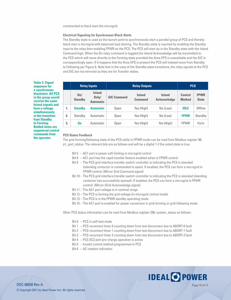
Electrical Signaling for Synchronous Black StartsThe Standby state is used as the launch point to synchronously start a parallel group of PCS and thereby black start a microgrid with balanced load sharing. The Standby state is reached by enabling the Standby input to the relay then enabling FPWR on the PCS. The PCS will start up in the Standby state with the Island Command high. When the On relay command is toggled the Island Acknowledge will be transmitted to the PCS which will move directly to the Forming state provided the Area EPS is unavailable and the GIC is correspondingly open. If it happens that the Area EPS is present the PCS will instead move from Standby to Following per Figure 5. Note that in the case of the Standby state transitions, the relay signals to the PCS and GIC are not mirrored as they are for Transfer states.
Relay Inputs Relay Outputs PCS
On/Standby
Island Only/
AutomaticGIC Command
Island Command
Island Acknowledge
Control Method
FPWR State
1. Standby Automatic Open Yes (High) No (Low) IDLE Offline
2. Standby Automatic Open Yes (High) No (Low) FPWR Standby
3. On Automatic Open Yes (High) Yes (High) FPWR Form
PCS Status FeedbackThe grid-forming/following state of the PCS while in FPWR mode can be read from Modbus register 96, p1_port_status. The relevant bits are as follows and will be a digital 1 if the noted state is true.
Bit 5 – AC1 port is power soft-limiting in microgrid controlBit 8 – AC1 port has the rapid transfer feature enabled when in FPWR controlBit 9 – The PCS grid interface transfer switch controller is indicating the PCS is islanded (islanding contactor is commanded to open). If enabled, the PCS can form a microgrid in
FPWR control. (Mirror Grid Command signal)Bit 10 – The PCS grid interface transfer switch controller is indicating the PCS is islanded (islanding
contactor has successfully opened). If enabled, the PCS can form a microgrid in FPWR control. (Mirror (Grid Acknowledge signal)
Bit 11 – The AC1 port voltage is in nominal rangeBit 12 – The PCS is forming the grid voltage (in microgrid control mode)Bit 13 – The PCS is in the FPWR standby operating mode Bit 15 – The AC1 port is enabled for power conversion in grid-forming or grid-following mode.
Other PCS status information can be read from Modbus register 298, system_status as follows:
Bit 0 – PCS in self-test modeBit 1 – PCS reconnect timer 0 counting down from last disconnect due to ABORT-0 faultBit 2 – PCS reconnect timer 1 counting down from last disconnect due to ABORT-1 faultBit 3 – PCS reconnect timer 2 counting down from last disconnect due to ABORT-2 faultBit 4 – PCS DC2 port pre-charge operation is activeBit 5 – Invalid control method programmed in PCSBit 6 – AC rotation indication
Table 3: Signal sequence for a synchronous blackstart. All PCS in the group would receive the same Island signals and form a voltage simultaneously at the transition from Standby to Forming. Bolded items are sequenced control commands from the operator.

Page 16 of 17DOC-00030 Rev A © Copyright 2017 by Ideal Power Inc. All rights reserved.
0 – AC1 port wired as A-B-C (0°, 240°, 120°) 1 – AC1 port wired as C-B-A (0°, 120°, 240°)Bit 9 – PCS power conversion is activeBit 10 – PCS hardware shutdown function is active (power conversion disabled)Bit 11 – PCS lockdown active due to GFDI fault, IMI fault, or fan faultBit 12 – PCS fault of severity level ABORT-0 activeBit 13 – PCS fault of severity level ABORT-1 activeBit 14 – PCS fault of severity level ABORT-2 activeBit 15 – PCS GFDI fault or IMI fault detected
Refer to the applicable product Modbus map for the full detail on all registers.
PCS Commissioning RequirementsFor the PCS to behave as described in this document and consistent with the Product Specification the following tasks should be performed at commissioning of a backup power system.
The PCS AC voltage and frequency control and telemetry must be calibrated for proper load droop response. With the AC input isolated or disconnected at each individual PCS in the system, enable voltage forming, ensuring no load is present and the voltage and frequency setpoints as per Table 2. Utilize a digital multimeter to measure the AC phase-to-phase voltage and frequency at the terminals of each PCS in the system. Adjust the following Modbus registers until the actual output voltage is as close as possible to the nominal setpoints of 480 Vac and 60 Hz.
Register 78 p1_voltage_setpt_offset Units of 0.25 VRegister 79 p1_freq_setpt_offset Units of 0.001 Hz
The 3-phase AC wiring and rotation must be validated. Confirm the phase rotation on the Area EPS at the service entrance to the facility. Energize the 3-phase supply to the AC input of each PCS in the system ensuring the PCS is offline (set to Idle). Rotation must be A-B-C and consistent throughout the Area EPS and Facility EPS. Attempting to start a PCS using FPWR into an A-C-B rotation will generate a fault.
13.0 SEL-547 SAMPLE CONFIGURATION
Ideal Power has demonstrated satisfactory operation with the SEL-547 Distributed Generator Interconnection Relay configurations described below. Please contact [email protected] to discuss your application and we may be able to supply SEL-547 software files per the configuration described in this Application Note. Please note that Ideal Power does not guarantee your local utility or AHJ will approve this configuration and Ideal Power does not engage with utilities regarding specific project implementation.
The SEL-547 is configured to monitor the facility side of the GIC for abnormal utility or island voltage or frequency, and will continuously monitor the GIC for proper operation. Based on this information the SEL-547 is able to control the GIC to open if the utility grid goes out of the specified range and provide fault indication indicative of both area EPS and island health as well as GIC functionality. The GIC auxiliary contact is used in monitoring for GIC functionality and the Area EPS/island health indication comes from the voltage and frequency trip criteria configured in the SEL-547.
Additionally, the SEL-547 monitors for an island black condition where all three phases must be below 55 Vac for 60 cycles. This is used when black starting the island from the Area EPS.The synchronization criteria used to reconnect the island to the area EPS are dictated by IEEE 1547.4 / IEEE 1547. For sites below 500 kVA the transition criteria dictate voltages must be within 10%, while frequency

Page 17 of 17DOC-00030 Rev A © Copyright 2017 by Ideal Power Inc. All rights reserved.
must be within .3 Hz and 20 degrees phase angle. For the Ideal Power application case the SEL-547 has been programmed to reconnect according to these criteria. The voltage calculation within the SEL-547 sets a bound of ±5 % around the nominal voltage as its allowable window thereby guaranteeing the reconnection voltage is within 10% between the two networks and within the ANSI C84.1 Range B limits. The 59.7 to 60.5 Hz frequency requirement is covered by the fault monitoring criteria. The IEEE 1547 phase angle requirement is internally managed by the SEL-547 during the final synchronism check discussed above. Additionally, a five (5) minute delay is implemented to delay reconnection after the area EPS has returned to the acceptable range.
The SEL-547 utilizes its three digital inputs driven by 24 Vdc signals. Input 1 is allocated to On/Standby control; Input 2 is used for the override commanded island only or automatic operation signal. Input 3 is allocated to the auxiliary contact of the GIC and is used to monitor for successful GIC operation either opened or closed.
The SEL-547 includes an RS-485 connection for Modbus communications which can provide device status and sense data to the system controller. All the operating logical variables in the SEL-547 control configuration may be monitored via this Modbus interface. Refer to SEL Documentation for more information.
Note that the SEL-547 is versatile in configuration options and Input 1 or 2 as described could also be set up to be controlled by a Modbus command signal. The Ideal Power default configuration however employs hardware signal inputs.
ADDITIONAL QUESTIONS?
Please contact: [email protected]
DISCLAIMERS AND INTELLECTUAL PROPERTY NOTICE
This document is provided “as is” and Ideal Power Inc. (IPWR) makes no representations warranties, expressed or implied, with respect to the information contained herein. IPWR has made reasonable efforts to ensure the accuracy of information herein at the time of publication; however, information is constantly evolving and IPWR does not purport the information provided is correct, comprehensive or exhaustive. This document is for informational purposes only; you should not act upon information without consulting IPWR or its authorized distributors.
© Copyright 2017, Ideal Power Inc. All rights reserved. No parts of this document may be reproduced in any form without the express written permission of IPWR. Ideal Power Inc., and the Ideal Power logo are trademarks of Ideal Power Inc. All other trademarks and service marks belong to their respective owners.
www.idealpower.com
4120 Freidrich Lane, Suite 100 Austin, Texas 78744