range design criteria - shooting academy range design.pdf · range design criteria ... firearms...
TRANSCRIPT

RANGE DESIGN CRITERIA
U.S. DEPARTMENT OF ENERGY Office of Health, Safety and Security
AVAILABLE ONLINE AT: INITIATED BY: http://www.hss.energy.gov Office of Health, Safety and Security


Range Design Criteria 10-01-08 i
TABLE OF CONTENTS
RANGE DESIGN CRITERIA...................................................................................................................... 1 1. Purpose ...................................................................................................................................... 1 2. Planning Factors ........................................................................................................................ 1 3. Planning Overview.................................................................................................................... 1
a. General Considerations ................................................................................................ 1 b. Type of Range .............................................................................................................. 1 c. Site Selection Preparation ............................................................................................ 2 d. Considerations.............................................................................................................. 3 e. Preliminary Design Stage............................................................................................. 3 f. Final Design Stage ....................................................................................................... 3
4. Outdoor Range Design .............................................................................................................. 4 a. Site Selection................................................................................................................ 4 b. Range Planning ............................................................................................................ 4 c. Surface Danger Zones .................................................................................................. 5 d. Support Facilities.......................................................................................................... 6 e. Design Criteria ............................................................................................................. 8
5. Indoor Range Design............................................................................................................... 15 a. Use of Indoor Ranges ................................................................................................. 15 b. Site Selection.............................................................................................................. 15 c. Range Planning .......................................................................................................... 17 d. Design Criteria ........................................................................................................... 17
6. Live Fire Shoot House............................................................................................................. 27 a. Introduction ................................................................................................................ 27 b. Site Selection.............................................................................................................. 27 c. Design and Layout ..................................................................................................... 28 d. Wall Construction ...................................................................................................... 28 e. Doors .......................................................................................................................... 29 f. Ceiling or Roofs ......................................................................................................... 29 g. Floors.......................................................................................................................... 29 h. Bullet Traps ................................................................................................................ 30 i. Elevated Observation Control Platform ..................................................................... 31
ATTACHMENT 1 -- RANGE DESIGN FIGURES ............................................................. Attachment 1-1
Range Design Criteria 10-01-08 1
RANGE DESIGN CRITERIA 1. PURPOSE. This document contains design criteria for U.S. Department of Energy
(DOE) live-fire ranges for use in planning new facilities and major rehabilitation of existing facilities. This document supersedes DOE M 470.4-3 Section B, Chapter II and will be approved and maintained by the Office of Security Policy, Office of Health, Safety and Security (HSS) as a stand-alone document on the HSS website.
2. PLANNING FACTORS. All applicable local, State, Federal, U.S. Environmental Protection Agency, Occupational Health and Safety Administration (OSHA), and National Environmental Policy Act requirements should be addressed and be reviewed annually (at least every 12 months) to incorporate any requirements changes that occur.
3. PLANNING OVERVIEW.
a. General Considerations.
(1) Live-fire range design should: (a) promote safe, efficient operation; (b) include provisions for ease of maintenance; and (c) be affordable to construct and maintain.
(2) Live-fire ranges should be designed to prevent injury to personnel and to prevent property damage outside the range from misdirected or accidental firing and ricochets. They should also be designed to direct ricochets away from the firing line inside the range.
(3) An open range may be established provided that enough distance and land area available to allow for surface danger zones (SDZs) appropriate for the weapons to be used. Lack of SDZs may require baffled ranges. Extreme weather conditions may necessitate indoor ranges.
b. Type of Range.
(1) Range requirements should be considered when determining the type and size of the range and the material to be used.
(2) The range should be suitable for training and qualifications for all courses of fire used on the site as set forth in the HSS-approved Firearms Qualification Courses.
(3) The range should be designed for shooting day and reduced-lighting DOE firearms courses, moving targets, multiple targets, and advanced shooting courses that may be required by the site.
(4) When determining whether the facility will be an indoor, open outdoor, partially baffled, or fully baffled range, the decision-making process should include site weather conditions, available land, available funding,
Range Design Criteria 2 10-01-08
and environmental, safety, and health considerations. The following additional factors should be considered.
(a) How many shooters must be accommodated?
(b) Will emphasis be on training or competitive activities?
(c) What types of firearms and range of ammunition will be used? (See Table 1.)
(d) Will the facility be used exclusively by DOE or will it be open to other organizations?
(e) What special uses will be made of the facility, e.g., advanced training, special weapons, or explosives?
(f) What lighting will be required, and what lighting is desired?
(g) What administrative space will be needed?
(h) What types of target mechanisms will be used?
(i) Will spectator safety areas be needed?
(j) What types of acoustics will be needed?
(k) How will lead contamination be controlled?
(l) Where will bullet traps be needed?
(m) Where will firearms cleaning and maintenance be performed?
c. Site Selection Preparation. The site selected should accommodate the required facility. It should meet acceptable standards for safety and have sufficient space, access, and acceptable zoning and construction costs. Land acquisition costs, future land values, and possible restrictions should also be examined. To ensure the project is feasible the following data should be considered.
(1) Documents. Copies of specific site, environmental, and construction criteria; applicable mandated regulations from the State, county, and local authorities; copies of ordinances, zoning regulations, soil conservation standards, health department requirements, and any other regulations that may pertain to the project should be obtained.
(2) Alternate Sites. Identify alternate sites, because one or more of the potential sites may be unsuitable or construction costs may be prohibitive.
Range Design Criteria 10-01-08 3
(3) Technical Data. Gather technical data relevant to each site including zoning maps, aerial photographs, topographic maps, and onsite ground and aerial information.
d. Considerations. The criteria to be considered in this process are:
(1) environmental restrictions, e.g., Endangered Species Act, Wilderness Act, and air and water pollution criteria;
(2) access, e.g., is it adequate or should a roadway be constructed to the site;
(3) construction cost, e.g., berms, baffles, barriers, earth moving;
(4) other restrictive Federal or State statutes and local ordinances; and
(5) community growth, especially in areas where urban growth is rapid. Escalating property values may make it unwise to construct in a particular area.
e. Preliminary Design Stage. The following preliminary design process is to be followed.
(1) Prepare:
(a) a preliminary layout sketch of each site;
(b) a draft document, which should include specifications for applicable zoning, building codes, environmental, safety, and health considerations, and other pertinent restrictions;
(c) alternative preliminary site plans showing different range layouts;
(d) a planning cost estimate; and
(e) a risk analysis report.
(2) Submit all zoning and building permit applications for approval. Be prepared, via the draft document, to present and, if necessary, defend the proposal at public hearings before zoning boards, health officials, and other governmental bodies involved in issuing permits.
f. Final Design Stage.
(1) The preliminary site plans include a layout of the proposed range with its accompanying safety fan in a cross section and top view.
(2) The range master/manager, training manager, safety manager, industrial hygienist, appropriate operating personnel and public works engineer
Range Design Criteria 4 10-01-08
should review the design requirements during the planning phase, before the construction drawings are started, and during the construction phase.
4. OUTDOOR RANGE DESIGN.
a. Site Selection.
(1) Outdoor range sites should be remote from other activities but accessible by road. SDZs should not extend across traveled roads, navigable waterways, railroads, or other areas.
(2) To protect against unauthorized access, SDZs should be controlled while firearms are being discharged. To prevent future encroachment, SDZs should be recorded on site maps.
(3) If other methods to control access to SDZs are not effective, then the zones should be fenced in. Natural barriers around the site, e.g., rivers, hills or a large drainage channel may be used to prevent encroachment and will ensure privacy. The best site is one with a natural backstop for projectiles to reduce the cost of constructing earth impact berms and to provide natural sound abatement.
(4) Outdoor ranges should be oriented to eliminate firing into the sun. The range should be oriented to the north or slightly to the northeast. The ideal direction is between due north and 25º northeast.
b. Range Planning.
(1) Firing into upward sloping land and land with natural backstops of hills or mountains is recommended.
(2) Firing platforms, access roads, and targets should be elevated above the flood level.
(3) The line of fire in rough terrain should be perpendicular to high ground. The line of fire on flat terrain should be free of knolls, ridges, and trees that reduce visibility.
(4) Known distance ranges should be as flat or evenly graded as possible. If the grade between the firing points and target does not exceed 2 percent, then the firing points may be below the target.
(5) Roads used for setting and servicing targets in impact areas and for maintenance of earth berm may be graded pathways. Roads in areas not subject to disturbance, e.g., vehicle parking areas, and roadways behind firing lines or out of range of weapons, should be designed for anticipated vehicle weight and usage.
Range Design Criteria 10-01-08 5
(6) The ground between the targets and firing line should be free of any hardened surface (smooth-surfaced walkways excepted) such as rocks or other ricochet-producing material.
(7) The surface may be sodded or planted with low-growing ground cover.
(8) The surface should be smooth, firm, and graded to drain away from the targets. A slight side-to-side grade of 1 percent to 2 percent should be provided for storm water runoff. For baffled ranges, the lateral slope should not exceed 2 percent because of the geometry of the baffle system.
(9) The overall size will be governed by the range distance and number of firing positions.
(10) Range distances from the firing line to the target are determined by the approved DOE qualification courses of fire for all weapons available for use by Protective Force (PF) personnel and by site-specific training courses of fire. The distances from the firing line to the target should be accurate to +.01 percent. It is important that any inaccuracy in the firing line-to-target distance is a greater, rather than lesser, distance (e.g., 101 yards for a 100-yard range instead of 99 yards).
(11) Shooters should have secure footing.
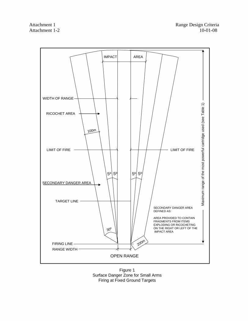
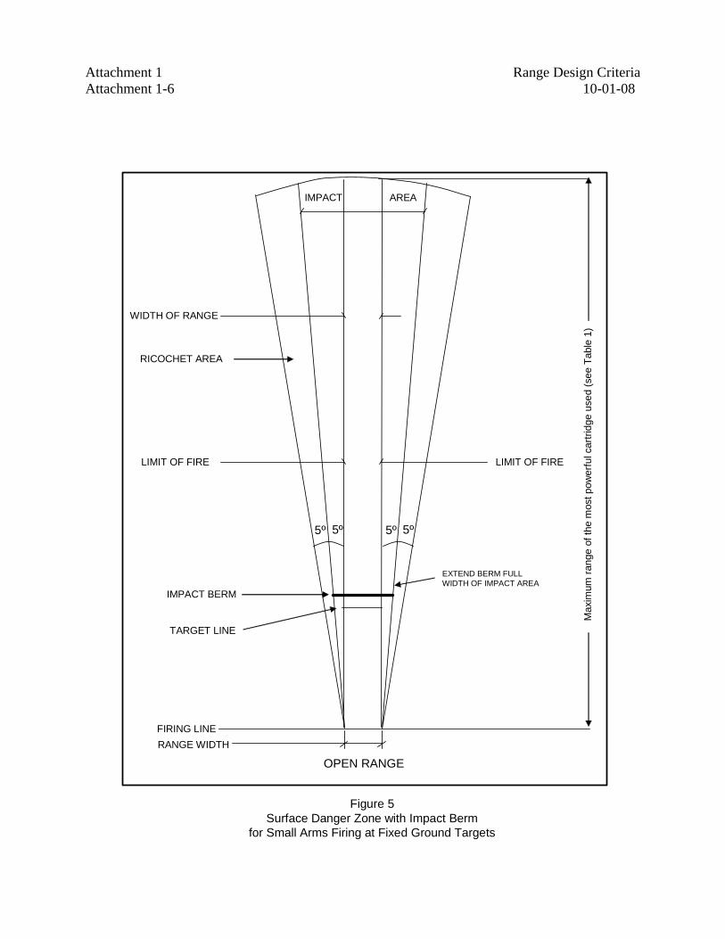
c. Surface Danger Zones. SDZs should be established to contain all projectiles and debris caused by firing ammunition and explosives (see Table 1). SDZ dimensions are dictated by the types of ammunition, types of targets, and types of firing activities allowed on the range. A basic SDZ consists of three parts: impact area, ricochet area, and secondary danger area (Figure 1). Figures 2 through 6 illustrate the application of the basic parts in the design of SDZs for various kinds of range activities.
(1) The primary danger area established for the impact of all rounds extends 5º to either side of the left and right limits of fire and downrange to the maximum range of any ammunition to be used on the range.
(2) The ricochet area is 5º to either side of the impact area and extends downrange to the maximum range of any ammunition to be used on the range.
(3) The secondary danger area is that area paralleling, and 100 yards outside of, the outermost limits of the ricochet area and extending downrange to the maximum range of any ammunition to be used on the range.
(4) Boundaries of SDZs must be posted with permanent signs warning persons of the danger of the live-fire range and prohibiting trespassing. The signs must be posted in a way that will ensure a person cannot enter
Range Design Criteria 6 10-01-08
the SDZ without seeing at least one legible sign (i.e., usually 200 yards distant or less).
(5) Limit of fire markers, both external and internal, must be placed to denote right and left limits of fire. Where cross firing is to be conducted, internal limit markers must be emplaced to denote internal right or left limits of fire from specific firing positions.
(6) Ranges may be located parallel to one another if in compliance with Figure 19 for separation.
(7) When there is insufficient distance to lay out a new range with the required SDZ or utilize other ammunition with a maximum range that does not exceed the SDZ, engineered or administrative controls can be used to control firing on that range. Permission to deviate from established SDZ requirements must be granted by the DOE cognizant security authority and supported by a safety risk analysis.
(8) Administrative controls such as use of the low-ready position or engineered controls such as muzzle traverse/elevation limiters can be used to control the firearm. Natural terrain such as a mountain or a hill provides an excellent backstop for firing. The terrain should be high enough to capture rounds fired at up to a maximum 15º muzzle elevation.
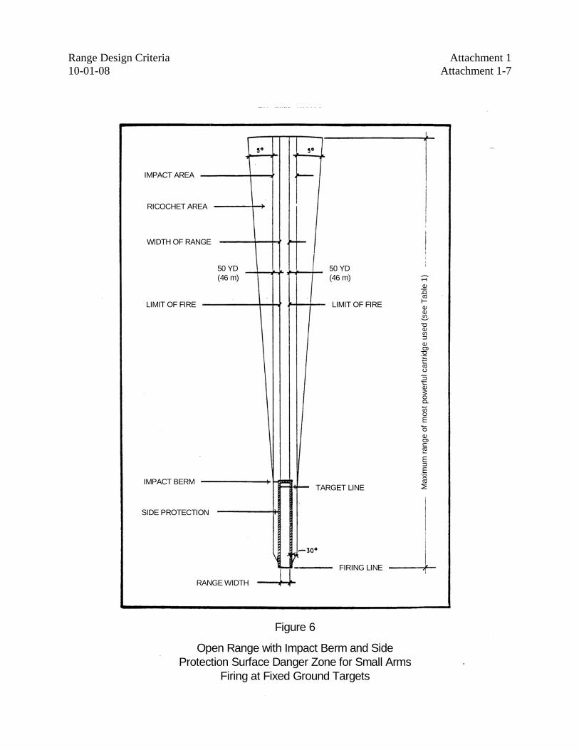
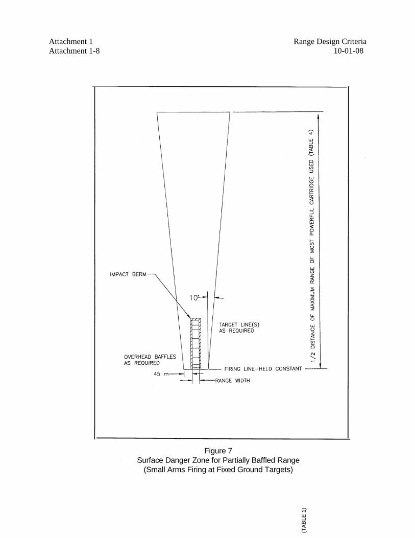
(9) To change the size and shape of an SDZ, baffles may be installed. Partial and full baffle systems consist of the following components: overhead baffles, a canopy shield over firing points, bullet impact berm, and side berms, sidewalls, or side baffles. A fully baffled range must be constructed so all direct fire can be contained within the range (see Figures 7 and 8).
d. Support Facilities. Range planners should consider the site-specific need for the following range support facilities.
(1) Targets.
(2) Target storage.
(3) Bunkers, trenches, and protective barriers for personnel protection.
(4) Range control towers.
(5) Toilets.
(6) Range poles, banners, markers, and signs.
(7) Communication systems.

Range Design Criteria 10-01-08 7
(8) Access and range roads.
(9) Parking areas.
(10) Potable water.
(11) Target maintenance.
(12) Ammunition storage.
(13) Power.
(14) Sewer.
(15) All other necessary utilities.
Table 1. Maximum Range of Small Arms Ammunition Maximum Range of Small Arms Ammunition
Caliber Maximum range of small arms
ammunition (distance in meters) .22 long rifle 1,400 .38 revolver Ball, M41 Ball PGU-12/8
1,600 1,900
.40 pistol Ball JHP Frangible
1783 1908 1000
.45 pistol 1,500
.45 submachine gun 1,600
.357 magnum 2,160 9mm pistol 1,740 9mm submachine gun 1920 .44 magnum 2,290 .50 machine gun Ball, M33 AP, M26
6,500 6,100
12 gauge shotgun, riot 00 buckshot 600 .30 rifle and machine gun Ball, M23 AP, M2
3,100 4,400
.30 carbine 2,300 5.56mm rifle Ball, M193
3,100
7.62mm rifle and machine gun Ball, M80 Match, M118
4,100 4,800
40mm M79 Mk-19 40mm
400
2200
Range Design Criteria 8 10-01-08
e. Design Criteria.
(1) Firing Line Items. Provide the following components.
(a) Floor Surface. The surface should be smooth, firm, and graded to drain away from the targets. A slight side-to-side grade of 1 percent to 2 percent should be provided for storm water runoff. Transverse firing line grading should match target line transverse grading. The distance between the firing line(s) must be sufficient to support the type of training conducted. Firing lanes must be clearly marked on the surface to match the targets. Depending on the number of personnel to be supported and the funds available, the following surfaces should be considered:
1 ground firmly compacted with mown grass;
2 sand or fine gravel;
3 wood decking of sufficient thickness and support to prevent movement; and
4 concrete topped with appropriate cushioning material.
(b) Overhead Containment. On partially and fully baffled ranges, a ballistic canopy (see Figure 9) should be provided over all locations where a weapon may be expected to be discharged (firing line, by definition). Figure 9 represents one construction approach, but the canopy must contain the direct fire effects of the most energetic round fired on the range. This canopy should begin at least 3 feet behind the firing line. General structural requirements may dictate more distance. The canopy should extend forward a minimum distance of 13 feet minimum, which will work geometrically with the first overhead baffle to prevent a weapon from firing directly out of the range (see Figures 16 and 17). The canopy should be constructed of ballistic material with sacrificial cladding as described below. Sound reduction ceiling waffles should be considered. Weather roofing is required above the ballistic material and it must slope sufficiently to drain.
(2) Firing Point. The depth of the firing point is determined by the shooting activity; e.g., rifle firing requires more depth than pistol firing.
(a) The minimum depth of the firing point is the area required for the shooter, shooter’s equipment, scorers, and range officers. For example, a pistol range might have a firing line approximately 6 to 10 feet deep, while a rifle range would have a firing line up to 20 feet deep. This variation is based on available space, type of
Range Design Criteria 10-01-08 9
shooting, size of target frames and carriers, and the spacing of target frames or carriers.
(b) For rifle ranges, each firing point should be 9 feet wide (see Figure 10). Firing lanes for pistols and shotguns should be 5 feet center to center (see Figure 11).
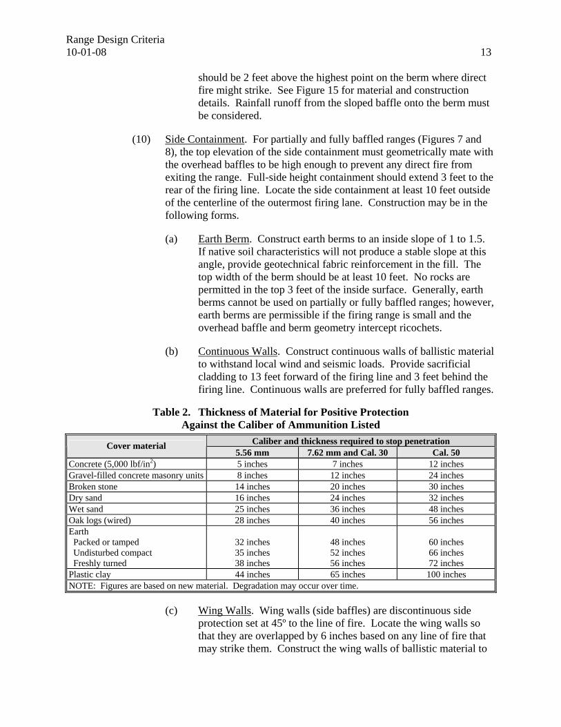
(3) Ballistic Material. The purpose of this material is to absorb, deflect, or fragment projectiles. Material for baffles on partially and fully baffled ranges is shown in Figures 12 and 18. Wood that is used should be of middle grade exterior timber or plywood. Timber in contact with the ground must be pressure-treated for this purpose. Avoid exposed connectors if possible. Refer to Table 2, Thickness of Material for Positive Protection Against the Caliber of Ammunition Listed, for the thickness of various materials.
(4) Sacrificial Cladding. Provide ¾-inch thick plywood with a ¾-inch air gap on any surfaces (baffles, wing walls, metal connectors, etc.) that are within 11 yards of the firing line to prevent back splatter.
(5) Firing Line Cover Material. The firing line should be covered to protect the shooter and allow activities to be held regardless of the weather. On ranges with several firing lines, the cover is generally installed at the longest firing distance. The firing line covers described below are for shelter only and should not be confused with the ballistic firing line canopies required on baffled ranges. Material that can be used for firing line covers includes wood, concrete, steel, and plastic. Most covers are constructed from wood products and are a shed or gable roof design. In some cases, corrugated metal or fiberglass roofing material can actually increase sound levels at the firing line and in areas around the range. Therefore, to reduce noise, corrugated metal or fiberglass roofing material should not be used unless it is acoustically treated. The structure should be designed to include the following:
(a) The shed roof should have a 6-inch (15cm) cavity filled with fiberglass insulation (or equivalent) and be enclosed on the bottom with 19mm (¾-inch) plywood or insulation board. Although this will not provide a completely effective sound barrier, sound waves will strike and penetrate the inside layer of plywood, and the sound will be reduced;
(b) A plywood shed roof should have a 15cm (6-inch) hollow core enclosed with a small grid mesh screen and a six-mil polymer barrier to retain the insulation. The intervening space should be filled with blown-in insulation to trap sound waves and reduce the drum effect of an open roof; and
Range Design Criteria 10 10-01-08
(c) A gable roof has a large hollow area above the joists; however, additional sound damping materials should be installed to reduce the drum effect and the sound pressure level as they are reflected onto the firing line area. The underside of the roof surface will require a minimum of 4 inches of insulation to fill in between the rafters and a minimum of 3 inches of insulation above the ceiling and between the joists. This will reduce the drum effect caused when sound waves strike surface material (e.g., corrugated metal) and will absorb a portion of the reflected sound waves.
(6) Surface Material. Positions should be hard-surfaced (e.g., concrete, gravel, wood, asphalt, or sod).
(a) For ranges where prone shooting is conducted, gravel or similar materials may cause difficulty for the shooter. When the surface material is concrete or asphalt, shooting mats or padding will be required when the kneeling or prone positions are used.
(b) For ranges with multiple firing lines, hard-surfaced firing lines located downrange of another firing line should be recessed or shielded from bullet impact to avoid ricochets off exposed edges.
(7) Landscaping. The site should be landscaped to provide for erosion control, noise abatement, maintenance, appearance, fire protection, and safety.
NOTE: Any landscaping will complicate the removal of lead in the berms, especially on impact surfaces, and will create higher maintenance costs.
(a) Berms should be planted with grass to prevent erosion. Ground cover is acceptable on existing berms that have been maintained and where erosion is not a problem.
(b) When grass is selected as a ground cover, it should be appropriate for the geographic area and should readily grow and provide good coverage. The degree of shading caused by overhead baffles will determine the type of grass for the range floor. Use grasses and cover for earth berms that will not be accessed by moving equipment so that natural growth heights will be acceptable. In areas where the soil is poor or extremely sandy, plants such as Bermuda grass, ice plant, or vine root can be used to control soil erosion.
(c) Heavy landscaping may be used to cut down on noise transmission. Plants and trees may be planted behind the firing position shelters to alleviate noise transmission problems.
Range Design Criteria 10-01-08 11
Soundproofing the firing line structures should be considered in problem areas. Trees should be kept away from firing lines to allow range control officers to see all shooters.
(d) For windbreaks, trees may be planted along the length of the range with partial side berms or wing walls where strong prevailing crosswinds are problems to shooting accuracy.
(e) Densely planted rows of fast-growing, compact, and thorny shrubs may be planted below the trees at ranges with partial berms or wing walls to abate noise, prevent encroachment, and alleviate crosswind problems.
(8) Target Line and Mechanisms. Components must be as follows.
(a) The target line should be a minimum of 30 feet from the toe of the impact berm. The distance between targets must be the same as the distance between firing positions.
(b) Target line bases must match grading with the firing line. Mechanical target support bases must be protected from the direct line of fire. They may be buried flush with the ground or placed behind a protective wall. Note that a small raised earth berm at this location generates significant ricochet. The complexity of the mechanism will dictate the protection requirement. See Figure 13 for wall or trench protection of high cost target line mechanisms.
(c) Target supports can be made of steel angles and channels, PVC pipe or wood. Do not use metal parts within 33 feet of the firing line where direct fire strikes are anticipated. Discharging weapons close to metal surfaces is extremely dangerous. Present the smallest surface area that is structurally sound to the line of fire to minimize ricochet. Design the target holders for easy and inexpensive replacement. Portable, self-supporting 2- by 4-inch wood frames or 2-inch by 2-inch wood plank placed into buried PVC pipe work well on simple ranges. The full face of the target must be visible to the shooter.
(d) Turning targets and the display time are at the discretion of the user. Commercially available, electrically motorized target carrier and electronic scoring systems should be considered where economically feasible.
(e) On open ranges, a single target line with multiple firing lines is preferred. On partially or fully baffled ranges, in most instances, a single firing line with multiple target lines will produce the most cost-effective range because of the firing line canopy. An
Range Design Criteria 12 10-01-08
extremely advanced target mechanism may be significantly more expensive than multiple canopies used to shift the advantage.
(9) Impact Structures. The structure varies depending on the type of range. Natural terrain such as a mountain, cliff, or steep hill may be incorporated into impact structures provided the completed structure complies with the minimum requirements of this Section. Acceptable structures by range type are listed below.
(a) For open ranges, the top elevation of the earth impact berm should be 26 feet above the range surface for ranges 100 yards long or longer and 16 feet above the range surface for ranges 50 yards long or less. The impact berm should extend 50 yards beyond where the target line ends for 100-yard-long ranges and 16 feet, or until joining with the side containment, if provided for ranges 50 yards long or less.
(b) The suggested elevation may be met by designing a combination of earth berm and vertical baffle (see Figure 14). The earth berm portion should have a top elevation of 16 feet above the surface of the range. The vertical baffle should be constructed of ballistic material and designed to withstand local seismic and wind loads. This combination arrangement would reduce the footprint and the amount of material in the earth berm.
(c) The preferred slope of the impact berm face is 1 to 1 or steeper. The steeper the slope, the more likely the berm is to absorb projectiles. The top should be 10 feet wide. The impact slope should be constructed with a 3-foot layer of easily filtered soil (to reclaim the lead projectiles) free of boulders, trees, rocks, stones, or other material that will cause ricochet. The rear slope should be appropriate to the native soil and maintenance requirements.
(d) For partially and fully baffled ranges, the top elevation of the impact structure will vary depending on the overhead baffle and impact structure arrangement. The impact structure for a partially baffled range can be: standard impact berm, bullet trap, or hybrid. For fully baffled ranges, the impact structure must be a bullet trap. In all instances, the impact structure must connect to the side containment. The top of the berm should be at an elevation 5 feet above the point where the highest line of direct fire can strike the berm.
(e) Outdoor bullet traps can be constructed by placing the last vertical overhead baffle over the last target line and placing a sloped baffle to connect from the top of the earth berm to the back of the last vertical baffle. The bottom of this lower-sloped overhead baffle
Range Design Criteria 10-01-08 13
should be 2 feet above the highest point on the berm where direct fire might strike. See Figure 15 for material and construction details. Rainfall runoff from the sloped baffle onto the berm must be considered.
(10) Side Containment. For partially and fully baffled ranges (Figures 7 and 8), the top elevation of the side containment must geometrically mate with the overhead baffles to be high enough to prevent any direct fire from exiting the range. Full-side height containment should extend 3 feet to the rear of the firing line. Locate the side containment at least 10 feet outside of the centerline of the outermost firing lane. Construction may be in the following forms.
(a) Earth Berm. Construct earth berms to an inside slope of 1 to 1.5. If native soil characteristics will not produce a stable slope at this angle, provide geotechnical fabric reinforcement in the fill. The top width of the berm should be at least 10 feet. No rocks are permitted in the top 3 feet of the inside surface. Generally, earth berms cannot be used on partially or fully baffled ranges; however, earth berms are permissible if the firing range is small and the overhead baffle and berm geometry intercept ricochets.
(b) Continuous Walls. Construct continuous walls of ballistic material to withstand local wind and seismic loads. Provide sacrificial cladding to 13 feet forward of the firing line and 3 feet behind the firing line. Continuous walls are preferred for fully baffled ranges.
Table 2. Thickness of Material for Positive Protection Against the Caliber of Ammunition Listed
Caliber and thickness required to stop penetration Cover material 5.56 mm 7.62 mm and Cal. 30 Cal. 50
Concrete (5,000 lbf/in2) 5 inches 7 inches 12 inches Gravel-filled concrete masonry units 8 inches 12 inches 24 inches Broken stone 14 inches 20 inches 30 inches Dry sand 16 inches 24 inches 32 inches Wet sand 25 inches 36 inches 48 inches Oak logs (wired) 28 inches 40 inches 56 inches Earth Packed or tamped Undisturbed compact Freshly turned
32 inches 35 inches 38 inches
48 inches 52 inches 56 inches
60 inches 66 inches 72 inches
Plastic clay 44 inches 65 inches 100 inches NOTE: Figures are based on new material. Degradation may occur over time.
(c) Wing Walls. Wing walls (side baffles) are discontinuous side protection set at 45º to the line of fire. Locate the wing walls so that they are overlapped by 6 inches based on any line of fire that may strike them. Construct the wing walls of ballistic material to
Range Design Criteria 14 10-01-08
withstand wind and seismic loads. Additionally, provide sacrificial cladding on wing walls closer than 30 feet to the firing line.
(d) End Walls. End walls may be constructed at the firing lane edge on the firing line in lieu of extending side containment 3 feet behind the firing line. Walls should be long enough to close off any line of sight between the end of the side containment and the rear 3 feet mark. The end walls should be constructed of ballistic material with sacrificial cladding extending from the canopy to the firing line surface.
(11) Overhead Baffles. Overhead baffles must be located so that no direct fire can exit the range from any firing position. The first overhead baffle must be geometrically coordinated with the firing line ballistic canopy (see Figure 9). The top elevation of the top of each following baffle should be 6 inches higher than a line of fire that just clears beneath each preceding baffle (see Figure 16). Overhead baffles should be the same height and spaced apart down range to achieve the required geometry (see Figure 17). The last baffle should be placed so the line of fire will strike the impact structure no higher than 5 feet below the top elevation of the structure. On a fully baffled range, the last overhead baffle must be over the last target line.
(a) On partially baffled ranges, overhead baffles must extend laterally to within 1 foot of the side containment. On fully baffled ranges, the overhead baffle must tie into the side containment.
(b) The vertical dimension of an overhead baffle when it is vertical varies with the number and spacing of the baffles. Normally, the height is between 5 and 8 feet when considering structural support size and costs.
(c) The baffles must be constructed of ballistic material. Baffles within 11 yards of the firing line should be covered with sacrificial cladding. See Figures 12 and 18 for possible configurations.
(d) Space the structural columns as far apart laterally as possible to open firing lanes. If possible, do not construct columns within the range. Design columns or beams to withstand local wind and seismic loads, and provide protective steel plate on the faces of the columns exposed to the firing line in accordance with Figures 12 and 18. Provide sacrificial cladding if the column is within 10 yards of the firing line. Overhead baffles may be placed on a flatter slope and overlapped to function as firing line canopies if multiple firing lines are to be used (see Figure 17). This arrangement is cost-effective for baffled combat lanes.
Range Design Criteria 10-01-08 15 5. INDOOR RANGE DESIGN.
a. Use of Indoor Ranges.
(1) Indoor ranges must be designed so projectiles cannot penetrate the walls, floor or ceiling, and ricochets or back splatter cannot harm range users. Considerations should be made for cleaning of all surfaces and handling of hazardous wastes.
(2) Lead exposure requirements must be reviewed for applicability.
b. Site Selection.
(1) Walls and Partitions. Indoor ranges must incorporate walls and partitions capable of stopping all projectiles fired on the range by containing or redirecting bullets to the backstop.
(2) Existing Buildings. If there are existing drawings of the facility, copies should be obtained from the original owner, architect, engineer, builder, or building permit. If original drawings of the building are not available, a sketch can be made of each floor of the building with a special emphasis on the load-bearing walls. The following considerations should be used when making the initial evaluation of an existing building.
(a) General Construction. Buildings constructed of wood products should be avoided. Modifications to reinforce the structure to support metal backstops or to reduce fire hazards may not be cost-effective.
(b) Exterior Walls. The type of exterior wall construction (e.g., masonry, wood, concrete, metal, combination, other) should be identified. Masonry buildings should be given primary consideration, especially those constructed on concrete slabs.
(c) Floors, Walls, and Ceilings. Floors, walls, and ceilings must be able to contain a bullet fired as well as the sound.
1 The ideal wall is made of poured concrete a minimum of 6 inches thick.
2 To aid in range cleaning, concrete floors should be finished so they have a nonporous surface.
3 Ceilings should be 8 feet high and enclosed to reduce air turbulence created by ventilation systems.
4 Evaluate the structural support designs of older buildings for their ability to withstand new loading. Original design
Range Design Criteria 16 10-01-08
considerations usually do not allow for installing heavy backstops and other range equipment.
5 To decide if modifications are necessary, slab buildings must be analyzed carefully to determine the capacity for floor loading. If there are no floor drains and it is economically feasible, modifications should also include adding one or more floor drains.
6 Ceiling joists may require strengthening to support baffles and shielding material.
(d) Electrical. Electrical needs may require the installation of heavy-duty wiring both internally and externally to accommodate the added power needs of range ventilation, heating, lighting and target-carrier mechanisms.
(e) Plumbing. Plumbing does not usually require major modifications; however, heavy metals may be prohibited from area wastewater treatment collection systems. Therefore, an approved filtration system may be necessary for disposal of hazardous waste material; e.g., lead.
(3) Precast Buildings.
(a) Precast concrete companies can provide complete precast buildings (job site-delivered) if engineering specifications for steel placement are provided on a set of plans (drawings) for the proposed building.
(b) Precast assembly allows for installation of a roof design more suitable for an indoor range. Gabled or hip roof designs should not be used.
(c) Hollow, precast concrete panels provide an option to bar joists, eliminating bullet ricochet or splatter. A flat bar joist design is the recommended alternative to hollow, precast concrete panels.
(d) The flat roof design also provides support for heating, ventilating, and air conditioning (HVAC) equipment outside of the range, which saves space and reduces cost.
(4) New Construction. New indoor construction projects require the same guidelines as existing buildings; however, they offer the advantage of building a structure specifically for an indoor shooting range.
Range Design Criteria 10-01-08 17
c. Range Planning. Design work for ventilation, wall structures, floors, ceiling, acoustics, backstops, and lighting will depend on how the range will be used.
(1) A determination for the type of building required includes the following considerations.
(a) Can the range be built in an existing building or is a new one required?
(b) How large should it be?
(c) How many shooters will it be expected to serve?
(d) Will it be used for competition?
(e) Should space be allowed for classrooms?
(f) How much will the facility cost?
(2) The planning process should include:
(a) obtaining ordinances, zoning regulations, building codes, soil conservation regulations and other information pertaining to legal requirements;
(b) for evaluation, identifying a site for a new building or several existing buildings that may have the suitable design characteristics; and
(c) gathering other technical information relevant to the project. This information includes zoning requirements, onsite information, and range design criteria. Local zoning codes or health department regulations normally will provide answers or solutions on how the project is to be handled.
d. Design Criteria. Based on the site selected, type of shooting, number of users, and site layout, the next step is to design the facility by preparing detailed drawings showing specifications and necessary dimensions. The four main considerations for indoor ranges are shooter needs, type of shooting activity, number of firing points, and number of users. Special consideration should be given to ventilation, lighting, safety baffles, and backstop design. The following standard and optional features for indoor ranges should be considered.
(1) Backstops and Bullet Traps.
(a) The design of a backstop or bullet trap is a contributing factor to the service life of the unit. Steel should be installed according to
Range Design Criteria 18 10-01-08
the type of ammunition to be used and to proven angle configurations.
(b) The design criteria should be based on the planned use of the facility. Metal plates selected for use in a backstop or trap must resist repeated stress according to the degree of stress applied. Necessary characteristics are resistance to abrasion, resistance to penetration, surface hardness, thickness, and alloyed strength to resist metal fatigue.
(c) The main backstop is generally a fabricated steel plate or series of plates used to stop bullets fired on a range. Backstop configurations and plate thickness will change according to type of shooting activity.
(d) Steel backstops with sand or water pits are common; however, a few indoor ranges use earthen or sand backstops.
CAUTION: Earthen or sand-filled backstops are not recommended because they can create health hazards for maintenance workers from silica and lead dust. They also cause excessive wear on ventilation fans.
(e) Backstops must extend from side to side and from ceiling to floor to protect the end of the range completely from penetration by direct bullet strike and prevent ricochets, back splatter, and splatter erosion of side walls.
(f) Four basic backstop and bullet trap designs are used for indoor ranges: Venetian blind, escalator, Lead-a-lator®, and the angled backstop (45º) back plate. Other backstop designs exist and should be researched for applicable use.
1 Venetian Blind Backstop. Requires less space, but without proper installation and regular maintenance it can cause back splatter problems from exposed edges of each main segment of the backstop. Keeping the exposed edges ground to original specifications is time-consuming, difficult, and requires skilled personnel.
a To control back splatter, a curtain should be hung in front of the backstop. Tests have been conducted on materials including canvas, burlap, cardboard, insulation board, and synthetic rubber. Properly installed, these materials effectively stop back splatter. Walls using insulation board or a synthetic rubber curtain are best.
Range Design Criteria 10-01-08 19
b The main advantage of the venetian blind backstop is minimal space requirements. While an angled plate or an escalator will use 14 feet of space, the venetian blind uses only 5 feet.
2 Escalator Backstop. Sets up with flat steel plates laid out on a framework sloping away from the shooter. Between each series of plates, an offset allows a bullet sliding down the facing surface to drop into a hidden tray for easy cleanup. At the top or back of the backstop, a swirl chamber is provided to trap the bullets or bullet fragments as they exit the backstop surface. Once the bullet’s flight ends in a spin-out chamber, the bullet or pieces fall into a cleanup tray.
3 Lead-a-lator®. A variation of the escalator-type backstop that uses a curved instead of flat piece of steel. The surface is concave and operates so that a bullet will follow the contour of the surface into a dry lead spinout chamber where it is trapped.
4 Angled Backstop (or 45º Inclined Plates). Uses a sand or water trap and has been the traditional alternative for indoor ranges.
a The angle of the plate should never exceed 45º from the ground. The 45º plate and pit backstop is relatively inexpensive, but there are several disadvantages. Sand traps require frequent cleaning to remove bullet fragments. Cleaning operations require workers to wear high-efficiency particulate air (HEPA) filter masks if material is removed dry. It is best to dampen the sand trap material before and during cleaning operations to eliminate dust. To maintain a healthier internal environment, frequent removal, disposal, and replacement of lead-laden sand is required. The surface should be continually raked to keep the sand level and to guard against splatter as lead buildup occurs.
b The cleaning operations are easier when a water trap is used. However, a water trap requires chlorine and other chemicals to retard algae growth and antifreeze in colder months to prevent freezing. Installing a water pit requires a different approach to foundations and footings, especially in areas affected by earthquakes or freezing.
Range Design Criteria 20 10-01-08
(2) General Range Cleaning. Both dry and wet methods can be used to clean the range. The method selected depends on the frequency of use. The wet method is preferred when floor drains are available, and keeping materials wet during cleaning operations reduces or eliminates release of microscopic dust particles. When dry methods must be used, workers must use the appropriate personal protective equipment (PPE) that has been established by local industrial hygiene personnel. After cleaning operations are complete, workers must shower and have work clothing laundered.
(3) Backstop Steel Plate Specifications.
(a) Steel plates supported by concrete or masonry should be anchored by expansion bolts or toggle bolts, as suitable for construction, with flush countersunk heads not more that 12 inches on center of all edges of each plate. Joints and edge lines should be backed with continuous ½-inch thick plate no less than 4 inches wide. Bolts should pierce both the facing and back plates. Expansion bolts should penetrate concrete not less than 2 inches. Steel plates must have milled edges at all joints.
(b) Joints must be butted flush and smooth. After the plates are erected, they must not have any buckles or waves. Exposed edges must be beveled at 42º to a fillet approximately ½-inch thick. There must be no horizontal joints in any steel plate work.
(c) Welding must meet the American Welding Society code for welding in building construction. Steel plates joined at, and supported on, structural steel supports must be spot-welded to steel supports not more than 6 inches on center.
(4) Baffles, Deflectors, and Shields. Baffles on indoor ranges protect lighting fixtures, HVAC ducts, ceilings, and target carrier apparatus. Baffles are designed to protect against the occasional errant bullet but not for repeated bullet strikes.
(a) To cover or protect vulnerable ceiling areas or range fixtures, baffles must extend the entire width of the range and downward. Spacing of baffles on a 50 to 75 feet range depends on the ceiling design. Range distance (firing line to target line) and height are factors. Ceilings must be impenetrable.
(b) Baffles or deflector plates must be used when modifying an existing building, especially in a building constructed of wood. This will prevent bullets from escaping or penetrating. Baffles should be a minimum of 10-gauge steel covered with a minimum of 1 inch of soft wood to prevent back splatter. The wood traps the
Range Design Criteria 10-01-08 21
projectile, whereas bare steel redirects it downward into the range area. A wood surface must be applied to overhead baffles, because ranges with untreated baffles usually show significant damage to concrete floors and often complete penetration through wood floors.
(c) Baffles should be installed at a 25º angle as measured from the horizontal plane of the ceiling. The baffle size and placement depends on what surface areas require protection. For example, ceiling baffles are wider than side baffles. See Figures 14 and 15 for baffle placement.
(d) Unlike baffles, deflectors are installed vertically and horizontally to redirect wide-angle shots into the backstop area. Deflector shields protect pilasters, leading edges of sand traps, bottom edges of backstops, doorways, windows, ventilation registers along the wall, etc. Deflectors are not covered with wood generally, but may be. These devices are also installed at a 25º angle either to the wall surface or floor. See Figure 16 for deflector installation.
(e) To protect ceiling areas, special impenetrable shields are installed above the firing line, especially in wood frame buildings.
1 Shields should extend the entire width of the range and 12 feet forward of the firing line. Floor shields may be required on wood floors.
2 Shields must be constructed from metal sheets according to planned use. For example, 10-gauge steel covered with a minimum of 1 inch of soft wood is effective in stopping most pistol calibers.
(5) Floors, Walls, and Ceilings. Indoor range facility floors, walls, and ceilings must be impenetrable; therefore, an existing building must have a structural analysis to determine loading factors that may exceed original design specifications. Wooden buildings may require modifications to support the increased weight. Specifications for new construction call for either poured-in-place concrete, pre-cast concrete, or dense masonry block. Solid cinder block should be used in place of hollow-core block. Specifications for modifying existing buildings call for adding additional materials to prevent bullet escape, which can be done with wood and steel laminated shields. Laminated shields can be constructed onsite by placing sheet-steel or steel plates between two sheets of ¾-inch plywood. While this method is more expensive than the extended booth design, it allows for an open firing line and better visibility for the range officer. Walls should be treated beginning 3 feet to the rear of, and extending forward of,
Range Design Criteria 22 10-01-08
the firing line until all vulnerable surfaces are protected. Acoustical material should be applied to the surfaces to aid in sound control.
(a) Floors. The range floor should be constructed by using a single pour and a fine, uniform-aggregate mix of concrete. Reinforcement should be No. 4 steel rods placed 12 inches on center along with 6- by 6-inch 8/8-gauge welded wire fabric. This may vary according to soil conditions. Very large floor areas may require two or more pours with expansion joints between each slab.
1 The floor should be designed to slope down toward the target line, beginning at the firing line, ¼-inch per foot.
2 The floor should be no less than 4 inches thick.
3 Floor size is governed by design. Larger size will result in higher costs for ventilation, lighting, heating, and overall building design. The decisions should be based on expected number of users versus overall cost.
(b) Floor Guards. Floor guards are provided to protect leading edges or protrusions, e.g., drains, traps or other protrusions from the floor area. Floor guards are designed to redirect errant bullets into the backstop area, which minimizes range damage.
1 Floor guards are constructed from 10-gauge steel and may be covered with wood.
2 Floor guards are installed horizontally along the floor surface parallel to the firing line.
3 Floor guards typically slope away from the firing line at a 25º angle to the horizontal.
4 Floor guards should extend only as high as necessary to protect exposed surfaces.
(c) Floor Drains. Floor drains should be constructed of cast iron soil pipe. The drain pipe should be attached to a lateral drain located 1 foot forward of the backstop floor guard. The drain pipe must lead to a filtration system approved by the cognizant environmental, safety, and health organization on the site.
(d) Walls. Poured concrete or masonry is preferred for wall construction, but wood may be used. Wall thickness must conform to acceptable engineering standards and comply with Federal, State, county and local zoning codes. Usually, no less than 3-inch
Range Design Criteria 10-01-08 23
thick, reinforced walls should be constructed to prevent the exit of any projectiles.
NOTE: This specification usually requires the use of steel or similar material where wooden walls are used. The size depends on building design, geological conditions, and climate. Size includes the height, thickness, and length of the running wall.
(e) Ceiling. Ceiling material should reduce sound, protect lighting devices, reflect light and be impenetrable. Typically, ceilings include 10-gauge steel baffles, 2- by 4-feet white acoustic panels, and clear-light panels.
1 The ceiling should be a minimum of 8 feet above the floor level and have an acoustically treated, smooth surface to allow for positive air movement downrange.
2 Baffles to protect adjoining areas should be above a false ceiling or designed into the roof/ceiling structure.
(6) Shooting Booths. Commercial or locally built shooting booths may be desirable on pistol ranges; however, they are not recommended for rifle ranges. Shooting booth panels can provide an impenetrable barrier between shooters, reduce sound levels, restrict the travel of brass, and act as a spray shield when revolvers are used.
(a) Shooting booths should be omitted for ranges that use only rifles.
(b) A shooting booth should never extend more than 18 inches behind the firing line because greater extension may obstruct the range control officer’s visibility.
(c) Bullets fired from any firearm used on the range must not be able to penetrate booth panels. The booth panel must be able to withstand the impact of a bullet fired at any angle to the surface and at point-blank range.
(d) Design criteria for the construction of booth panels are as follows:
1 Cover the 10-gauge steel plate with a nominal 2 inches of soft wood. In a series of tests using 10-gauge steel plate, firing all lead bullets at right angles, the plate covered with a nominal 2 inches of soft wood withstood direct hits from all standard pistol calibers up to, and including, .44 caliber magnum;
Range Design Criteria 24 10-01-08
2 Use special acoustical materials to ensure that panels reduce muzzle blast effects on all shooters and range personnel;
3 Ensure that panels do not restrict airflow;
4 Ensure that panels do not restrict the range officer’s visibility of the firing line; and
5 Construct panels so they extend from the floor to a minimum height of 6 feet. Panels should be ceiling height.
(7) Target Carriers and Turning Mechanisms. An indoor range can be operated more efficiently and safely by installing a target transport system. This system may be a simple, hand-made device or a completely automatic, electrically powered system. Either one will enhance safety by eliminating the need to walk downrange to replace targets. Target carrier systems speed up range operations. A turning target mechanism is available that faces the target parallel to the line of sight and then turns the target 90º to the line of sight to begin the stated time period. The target carriers should position the targets in the approximate center of the backstop.
(8) Control Booth. Range control booths must allow for maximum visibility and provide for easy access into and out of the range and ready area. The control booth should provide seclusion from and immediate access to the range environment. This design protects the range officer from frequent exposure to high sound levels and lead emissions.
(9) Communications. A communications system capable of relaying range commands distinct and separate from the sounds generated by shooting activities is required. Communications systems must account for shooters who wear two pairs of hearing protectors and persons who have substantial hearing loss.
(10) Ventilation and Filtering Systems. This section deals with the design or redesign of ventilation systems for indoor firing ranges. Administrative or engineering controls must be instituted to prevent shooters from being exposed to airborne lead levels exceeding acceptable limits. Administrative controls are used either when engineering controls fail to reduce exposure or when range use exceeds HVAC system specifications. Administrative controls are especially applicable to reducing risks on existing ranges.
(a) Administrative controls used to reduce exposure levels on an indoor range must be rigidly followed and enforced, and
Range Design Criteria 10-01-08 25
compliance must be recorded in a log book for purposes of analysis and reference.
(b) The following administrative controls are provided and must be used where individuals are frequently exposed to airborne lead.
1 Provide range maintenance personnel with appropriate PPE, e.g., safety glasses and respirators.
2 Provide proper HEPA filter cleaning equipment. The equipment must be able to remove accumulated lead dust from floors, walls, and ledges and must include attachments capable of removing lead-laden sand from the backstop area.
(c) A ventilation system must be installed that will provide clean air in the user’s breathing zone to reduce exposure to potentially dangerous materials to safe levels.
(d) Adopt administrative controls that monitor and control exposure time for a given user and/or assigned range personnel.
(11) Lighting.
(a) A visually safe facility should be free of excessive glare and major differences in light levels. Therefore, floors and ceilings should be designed to provide light reflection. In the event of a power outage, battery-powered emergency lighting must be provided for emergency exits.
(b) Rheostat-controlled lighting fixtures, which can reproduce near-daylight and low-light conditions, are best suited for indoor ranges. Range lighting involves three systems: general lighting, local lighting, and semi-direct lighting.
1 General lighting provides uniform light levels over the entire range area and adjoining areas and is usually installed in a symmetrical arrangement to blend with the architecture.
2 Local lighting supplements general lighting along the firing line to provide better visibility for those tasks associated with the loading and firing of firearms.
3 Semi-direct lighting distribution directs 60 to 90 percent of the lighting on the target with a small upward component to reflect from the ceiling and walls to soften shadows and generally improve range brightness. When ceilings are
Range Design Criteria 26 10-01-08
white, lighting fixtures mounted too close together create excessive glare.
(c) Lamp specifications for general lighting must be adjustable to provide 0.2 to 50 foot-candles of luminance measured at a point 7 yards from the target line. Local lighting should produce 0.2 to 60 foot-candles of luminance on the firing line. Semi-direct lighting on the targets should achieve 0.2 to 100 foot-candles of luminance. Glare should be reduced or eliminated by incorporating pastel colors in the interior design.
(d) Lighting designs should also seek to balance the color of light emissions. For example, most fluorescent fixtures produce high levels of blue, which alone are not suitable for indoor ranges. If fluorescent fixtures are used, green tubes or other light sources should be installed to balance the colors.
(12) Plumbing. Plumbing requirements specify that there must be a fresh water supply for personal hygiene and for range cleaning chores. There also must be a waste removal system for normal waste material and material removed from the range. An approved filtration system must be provided for range cleaning waste. Floor drains should be connected to this alternate waste system. Restrooms, showers, and sinks should be connected to a regular sewer system.
(13) Sound Control. Sound control on indoor ranges includes two distinct components: airborne and structure-borne sound. For airborne sound, all leaks into outer areas should be sealed, which includes airtight insulation around doors, windows, HVAC ducts, walls, and ceilings. Structure-borne sound reduction is necessary to protect adjoining, occupied rooms. Acoustical material should be applied to walls, HVAC ducts, floor, and ceiling areas.
(14) Range Control. Range control provides rules and supervision that encourage safe and proper use of a range. Safety devices control the physical use of an indoor range and may include warning lights, alarm bells, switch locations, etc. For example, an indoor range with a door in the downrange area should be equipped with an alarm. The door could also be secured by a mortise lock or barred from within but must remain a fire exit. Fire codes generally prohibit bars on doors that would delay escape from a building. Emergency personnel must be able to access the doors. Any door that can be accessed from the outside must be marked with warning devices to indicate when the range is in use. When installing doors on indoor ranges, refer to Life Safety Code National Fire Protection Association (NFPA) 101.
Range Design Criteria 10-01-08 27
(15) Target Carriers. Target carriers are used for the convenience of shooters to allow them to continue shooting without delay when target changes are necessary. For health considerations, target carriers keep shooters out of the high lead concentration areas and safely behind the firing line.
(16) Heaters. Protected heating units should be installed behind and above the firing position to provide a comfort zone for shooters.
(17) Gun Racks. Gun racks should be mounted behind the firing positions as an additional safety feature to reduce gun handling and to keep the range areas orderly. Appropriate material should be used to construct the gun racks, and the design must correspond to the weapons being used.
6. LIVE FIRE SHOOT HOUSE.
a. Introduction.
(1) A live fire shoot house (LFSH) is intended for use in advanced tactical training for Security Police Officers. Use of this facility includes individual tactics or Special Response Team force option training. All LFSHs must have an elevated observation control platform (EOCP). The following sections illustrate recognized construction methods for LFSHs. However, they do not eliminate the requirement for sound professional engineering design and validation.
(2) Administrative controls not directly related to design and construction must be in place during facility use. The administrative controls and engineering design allow for a reduction in physical barriers that prevent rounds from escaping the facility. Designed barriers must prevent a round fired with a vertical upward error of 15º from escaping the facility.
b. Site Selection.
(1) Site selection for an LFSH is similar to that for any range facility. Terrain features, noise, and availability of utilities and access roads must be considered, as already discussed in previous sections for indoor and outdoor ranges. The LFSH should be placed adjacent to other range facilities whenever possible so that it may utilize the same support facilities, access roads, etc.
(2) Facility design, target and shooter placement, and other administrative controls minimize the possibility of rounds being fired over the top of the walls and leaving the structure and mitigate the need for an SDZ outside the confines of the LFSH proper.
Range Design Criteria 28 10-01-08
c. Design and Layout.
(1) The interior layout of the facility is based on the mission and training requirements of the site. Facility design should incorporate a wide variety of room configurations. Some of the room configurations that should be considered are: multiple floors, an L-shaped room, stairwells, rooms within a room, hallways, and closets.
(2) The floor plan design should accommodate the movement of target systems, bullet traps, and other equipment into and out of the LFSH.
(3) Exposure to airborne contaminants for a fully enclosed LFSH must be controlled by adequate ventilation. The lighting requirements are similar to those for indoor ranges.
d. Wall Construction.
(1) Wall Height. Exterior walls of the LFSH must be designed to absorb the most energetic projectile identified for use within the facility. Wall height must be a minimum of 8 feet. The wall height should allow a maximum error angle of 15º from horizontal standing shooting distance from the target and still enable a projectile to be contained by the wall, which can be described by the following equation: Wall Height is equal to the muzzle height plus 0.27 (tangent 15°) times the target distance. The following table assumes a muzzle height of 5 feet.
Distance from Muzzle to Ballistic Wall (Feet) Wall Height (Feet) 11' 1" 8' 0" 13' 3" 8' 6" 14' 10" 9' 0" 17' 0" 9' 6" 18' 6" 10' 0" 20' 9" 10' 6" 22' 2" 11' 0" 24' 5" 11' 6" 25' 11" 12' 0"
If the distance from muzzle to ballistic wall exceeds the required wall height, other administrative, engineering or natural ballistic wall controls must be administered or considered such as shooter-to-instructor ratio, canopies, baffles, natural terrain, existing SDZ, standard operating procedures, and training.
(2) Ballistic Walls. Ballistic interior walls are the preferred method of construction. Where non-ballistic interior walls are used, additional administrative controls must be applied to target placement and team
Range Design Criteria 10-01-08 29
choreography. Ballistic walls are required in all cases where containment of the round and protection of personnel is paramount.
(a) Footings. Footings must be designed using the engineering criteria that best ensures structural integrity and stability of wall construction.
(b) Composite Walls.
1 A combination of ¾-inch exterior grade plywood and steel is effective. Minimum thickness will be ¼-inch mild steel with an exterior-grade plywood separated by a minimum of ¾ inch with a maximum of 1½ inches from the steel surface.
2 Other combinations are possible. The main criterion is that the wall must stop any round fired and contain bullet fragments.
(3) Non-Ballistic Walls. These walls are constructed of materials that offer no protection to personnel or equipment in adjoining rooms. Material used for these walls must not contribute to or enhance ricochet or splatter. Additional administrative controls must be applied such as target placement and team choreography.
e. Doors. All doors must be constructed of wood with no glass. Additionally, at least a portion of the rooms must have working doors, some opening inward, some opening outward, and doors opening left and right.
NOTE: All devices in the LFSH, such as brackets and hangers, used to secure walls to floors or secure doors must be covered or protected to mitigate any tripping or ricochet hazards.
f. Ceiling or Roofs. Ceilings or roofs can be of value when the shoot house is required for year-round use in areas with severe weather conditions. Exposure to airborne contaminants must be controlled by adequate ventilation. The lighting requirements for fully enclosed shoot houses are similar to those for indoor ranges. When training exercises require target placement above the wall design, the ceiling or roof must be protected unless firing into an approved SDZ.
g. Floors.
(1) Floor construction must be selected for its ability to absorb direct fire, minimize ricochets, and provide a walking surface free of slipping/tripping hazards. Floors should provide the same ricochet protection as walls. Options include:
Range Design Criteria 30 10-01-08
(a) exterior-grade plywood floor constructed in accordance with American Plywood Association guidelines over smooth finished concrete;
(b) concrete with brushed surface that minimizes slip and tripping hazards;
(c) asphalt;
(d) exterior-grade plywood;
(e) shredded bias-ply tires; and
(f) earth, free of rocks and debris that could cause ricochet.
(2) Construction joints between walls and floors must be designed to contain projectiles within the LFSH.
h. Bullet Traps.
(1) General Information.
(a) Targets used in LFSHs must be placed so that fire is directed into a bullet trap designed to capture the rounds.
(b) Bullet traps must be constructed to contain the most energetic projectile to be fired into them without dimpling/pitting the steel and contain splatter and fragments in all directions. The size and shape of a bullet trap may be altered, but materials may not be substituted.
(2) Specifications for construction.
(a) 5.56mm conventional ammunition must not be used when shooting into bullet traps without further testing and development of containment materials. Only 5.56mm non-toxic frangible ammunition can be used.
(b) Bullet trap steel must be set at a minimum 7º angle off vertical based on the most probable line of flight of the bullet. The greater the angle of the bullet trap, the less the deterioration on the steel plate. A bullet trap constructed similar to the DOE National Training Center design (see Figure 20) and then leaned against the wall of the shoot house with the base of the trap out approximately 1 foot provides adequate angle of the steel backing.
(c) Bullet trap steel must be constructed of a minimum ¼-inch, 500 Brinell hardness or equivalent rifle-grade steel. Quality
Range Design Criteria 10-01-08 31
assessment and ballistic test sheets certifying the grade and quality of the steel backing plate must accompany every steel backing plate utilized.
(d) An anti-splatter shield must be used in front of the steel to prevent back splash. Two layers of 7/16-inch nylon-impregnated rubber belting material or ¼-inch self-sealing co-polymer sheeting are good examples of material to use.
(e) An air space must be left between the face of the steel and the facing material to allow fragments to collect in the rear of the trap. A 1¾ -inch air space is an accepted construction standard.
(f) Linatex™ rubber backing material between the fascia and steel backing plate is not recommended because it deteriorates rapidly when using 5.56mm frangible ammunition.
(g) Plywood under the fascia material and in front of the steel plate is not recommended because the material deteriorates rapidly with 5.56mm frangible ammunition.
(h) Bullet traps must be constructed for easy inspection of the inside of the fascia material and the front of the steel plate. Frequent inspection of the interior of the bullet traps must be conducted when rounds are fired into one general area.
(i) The fascia material must be inspected, replaced or repaired when the integrity of the fascia material allows the round to start dimpling the steel backing plate.
(j) The bullet trap steel backing plate, when used in the standard bullet trap design, must be replaced when 50 percent of the material in one general area has been chipped away.
(k) The requirement to remove from service any steel target when dimples exceed 1/16 inch does not apply. Steel backing plates must have a protective cover installed between the plate and the shooter that protects the shooter from back splash.
i. Elevated Observation Control Platform.
(1) EOCPs enhance the ability to observe and control LFSH operations. Administrative controls must be considered when constructing the EOCP. Platform construction and location is based on the training to be conducted. EOCPs must be constructed in accordance with all applicable regulations for elevated work platforms.
(2) EOCPs must be constructed to:
Range Design Criteria 32 10-01-08
(a) maximize instructors’ observation and control of the entry team fire and movement;
(b) facilitate communication between instructors on the EOCP and the floor;
(c) position the lowest point of the horizontal walking surface higher than the 15° vertical error for any target engaged;
(d) provide ready access;
(e) integrate instructors’ movement with team flow;
(f) maximize instructors’ ability to see shooters clearly at all times; and
(g) have supporting structures placed so that they pose no additional hazards such as tripping, ricochet, splatter, etc.
Range Design Criteria Attachment 1 10-01-08 Attachment 1-1
ATTACHMENT 1 -- RANGE DESIGN FIGURES
Figure 1. Surface Danger Zone (SDZ) for Small Arms Firing at Fixed Ground Targets
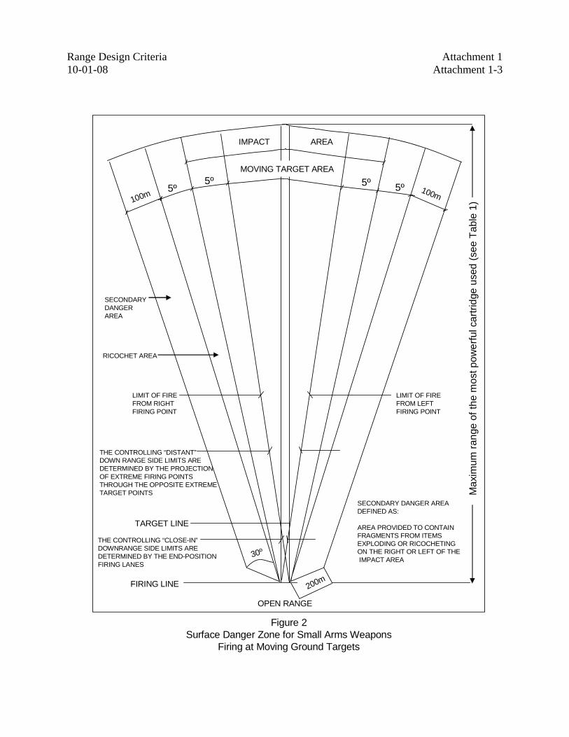
Figure 2. SDZ for Small Arms Weapons Firing at Moving Ground Targets
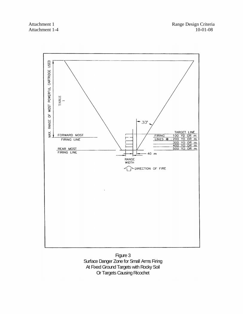
Figure 3. SDZ for Small Firing at Fixed Ground Targets with Rocky Soil or Targets Causing Ricochet
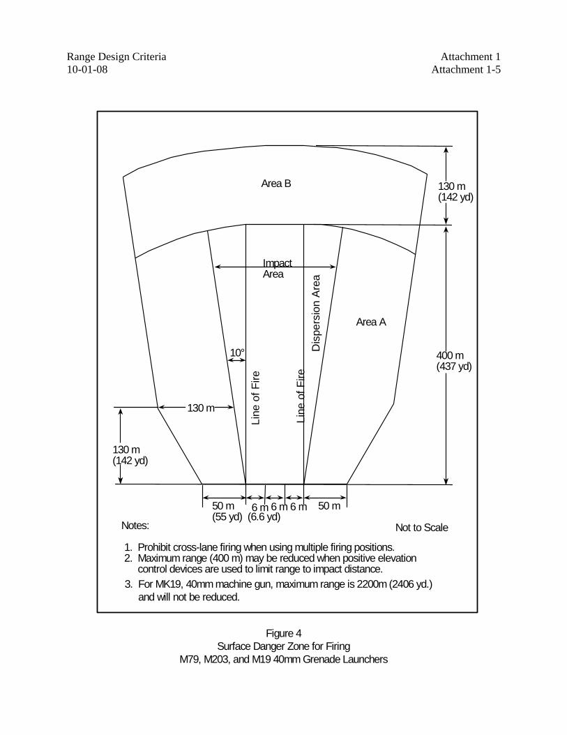
Figure 4. SDZ for Firing M79, M203, and M19 40 mm Grenade Launchers
Figure 5. SDZ with Impact Berm for Small Arms Firing at Fixed Ground Targets
Figure 6. Open Range with Impact Berm and Side Protection SDZ for Small Arms Firing at Fixed Ground Targets
Figure 7. SDZ for Partially Baffled Range (Small Arms Firing at Fixed Ground Targets)
Figure 8. SDZ for Fully Baffled Range (Small Arms Firing at Fixed Ground Targets)
Figure 9. Ballistic Overhead Canopy
Figure 10. Outdoor Rifle Range Layout
Figure 11. Pistol Range Layout
Figure 12. Ballistic Material
Figure 13. Ballistic Protection of Target Mechanism
Figure 14. Impact Berm for Open and Partially Baffled Ranges
Figure 15. Outdoor Bullet Trap
Figure 16. Baffle Range Profile
Figure 17. Baffle System Geometry
Figure 18. Overhead Baffle Ballistic Designs
Figure 19. Parallel Ranges
Figure 20. National Training Center Bullet Trap
Attachment 1 Range Design Criteria Attachment 1-2 10-01-08
Max
imum
rang
e of
the
mos
t pow
erfu
l car
tridg
e us
ed (s
ee T
able
1)
IMPACT AREA
WIDTH OF RANGE
RICOCHET AREA
100m
LIMIT OF FIRE LIMIT OF FIRE
SECONDARY DANGER AREA
5º 5º 5º 5º
TARGET LINE
FIRING LINE
30º
200m
RANGE WIDTH
OPEN RANGE
SECONDARY DANGER AREADEFINED AS:
AREA PROVIDED TO CONTAINFRAGMENTS FROM ITEMS EXPLODING OR RICOCHETINGON THE RIGHT OR LEFT OF THEIMPACT AREA
Figure 1Surface Danger Zone for Small Arms
Firing at Fixed Ground Targets
Range Design Criteria Attachment 1 10-01-08 Attachment 1-3
Max
imum
rang
e of
the
mos
t pow
erfu
l car
tridg
e us
ed (s
ee T
able
1)
30º
100m 100m5º5º
5º 5ºMOVING TARGET AREA
IMPACT AREA
TARGET LINE
FIRING LINE 200m
THE CONTROLLING “CLOSE-IN”DOWNRANGE SIDE LIMITS AREDETERMINED BY THE END-POSITIONFIRING LANES
THE CONTROLLING “DISTANT”DOWN RANGE SIDE LIMITS AREDETERMINED BY THE PROJECTIONOF EXTREME FIRING POINTSTHROUGH THE OPPOSITE EXTREMETARGET POINTS
LIMIT OF FIREFROM LEFTFIRING POINT
LIMIT OF FIREFROM RIGHTFIRING POINT
RICOCHET AREA
SECONDARYDANGERAREA
SECONDARY DANGER AREADEFINED AS:
AREA PROVIDED TO CONTAINFRAGMENTS FROM ITEMS EXPLODING OR RICOCHETINGON THE RIGHT OR LEFT OF THEIMPACT AREA
OPEN RANGE
Figure 2Surface Danger Zone for Small Arms Weapons
Firing at Moving Ground Targets
Attachment 1 Range Design Criteria Attachment 1-4 10-01-08
Figure 3Surface Danger Zone for Small Arms FiringAt Fixed Ground Targets with Rocky Soil
Or Targets Causing Ricochet
TAB
LE
1
Range Design Criteria Attachment 1 10-01-08 Attachment 1-5
6 m 6 m 6 m
Area B
Area A
10°
Impact Area
Line
of F
ireD
ispe
rsio
n A
rea
50 m (55 yd)
Not to ScaleNotes:
1. Prohibit cross-lane firing when using multiple firing positions. 2. Maximum range (400 m) may be reduced when positive elevation
control devices are used to limit range to impact distance.
50 m
Line
of F
ire
130 m (142 yd)
400 m (437 yd)
130 m (142 yd)
130 m
(6.6 yd)
3. For MK19, 40mm machine gun, maximum range is 2200m (2406 yd.)and will not be reduced.
Figure 4Surface Danger Zone for Firing
M79, M203, and M19 40mm Grenade Launchers
Attachment 1 Range Design Criteria Attachment 1-6 10-01-08
Max
imum
rang
e of
the
mos
t pow
erfu
l car
tridg
e us
ed (s
ee T
able
1)
IMPACT AREA
WIDTH OF RANGE
RICOCHET AREA
LIMIT OF FIRE LIMIT OF FIRE
IMPACT BERM
5º 5º 5º 5º
TARGET LINE
FIRING LINERANGE WIDTH
OPEN RANGE
EXTEND BERM FULLWIDTH OF IMPACT AREA
Figure 5Surface Danger Zone with Impact Berm
for Small Arms Firing at Fixed Ground Targets
Range Design Criteria Attachment 1 10-01-08 Attachment 1-7
Figure 6
Open Range with Impact Berm and Side Protection Surface Danger Zone for Small Arms
Firing at Fixed Ground Targets
IMPACT AREA
RICOCHET AREA
WIDTH OF RANGE
50 YD(46 m)
50 YD(46 m)
LIMIT OF FIRE LIMIT OF FIRE
IMPACT BERMTARGET LINE
SIDE PROTECTION
RANGE WIDTH
FIRING LINE
Max
imum
rang
e of
mos
t pow
erfu
l car
tridg
e us
ed (s
ee T
able
1)
Attachment 1 Range Design Criteria Attachment 1-8 10-01-08
Figure 7Surface Danger Zone for Partially Baffled Range
(Small Arms Firing at Fixed Ground Targets)
(TA
BLE
1)
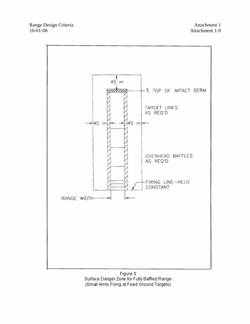
Range Design Criteria Attachment 1 10-01-08 Attachment 1-9
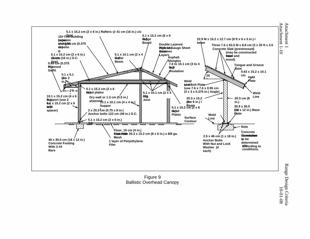
Attachm
ent 1 R
ange Design C
riteria A
ttachment 1-10
10-01-08
15# Felt building paper between shingles and 0.95 cm (0.375 in.) sheeting.
0.95 cm (0.375 in.) Plywood Soffit
5.1 x 5.1 cm (2 x 2 in.)
10.1 x 15.2 cm (4 x 6 in.) Support (use 2 ea. 5.1 x 15.2 cm (2 x 6 in.) with spacer) 2 x 20.3 cm (0.75 x 8 in.)
Anchor bolts 122 cm (48 in.) O.C.
5.1 x 15.2 cm (2 x 6 in.) Sill
5.1 x 15.2 cm (2 x 6 in.) Head plates
Dry wall or 1.3 cm (0.5 in.) plywood10.1 x 10.1 cm (4 x 4 in.)
Support
5.1 x 10.1 cm (2 x 4 in.) Clg. Joist
5.1 x 15.2 cm (2 x 6 in.) Joists 41 cm (16 in.) O.C. (typ)
5.1 x 15.2 cm (2 x 6 in.) Rafters @ 41 cm (16 in.) c/c (typ)
5.1 x 10.1 cm (2 x 4 in.) Collar Beam
Double Layered Plywood With 10 Gauge Sheet Steel Between Layers
Asphalt Shingles 7.6 to 10.1 cm (3 to 4 in.) Roll Insulation
5.1 x 15.2 cm (2 x 6 in.) Head Plates
Floor, 10 cm (4 in.) Concrete Slab With 20.3 x 15.2 cm (8 x 6 in.) x 8/8 ga. Mesh
1 layer of Polyethylene Film
46 x 30.5 cm (18 x 12 in.) Concrete Footing With 3 #4 Bars
2'8"
25°Weld
Line and Bolt Plate (use 7.6 x 7.6 x 0.95 cm (3 x 3 x 0.375 in.) Angle]
20.3 x 15.2 cm (8 x 6 in.) I Beam
20.3 cm (8 in.)
Weld Line
30.5 x 30.5 cm (12 x 12 in.) Base Plate
Surface Contour
22.9 M x 15.2 x 12.7 cm (9 ft x 6 x 5 in.) I beam
(may be constructed from steel and wood)
Tongue and Groove Joint
0.63 x 15.2 x 10.1 cm Hold
Plate
Weld Line
Note: Concrete foundation dimensions to be determined according to site conditions.
2.5 x 46 cm (1 x 18 in.) Anchor Bolts With Nut and Lock Washer (4 each)
Three 7.6 x 63.5 M x 8.8 cm (3 x 25 ft x 3.5
5.1 x 15.2 cm (6 x 6 in.) Ridge Board
Figure 9 Ballistic Overhead Canopy
Concrete Slab (prestressed)
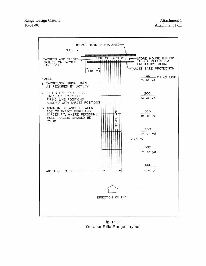
Range Design Criteria Attachment 1 10-01-08 Attachment 1-11
Figure 10Outdoor Rifle Range Layout
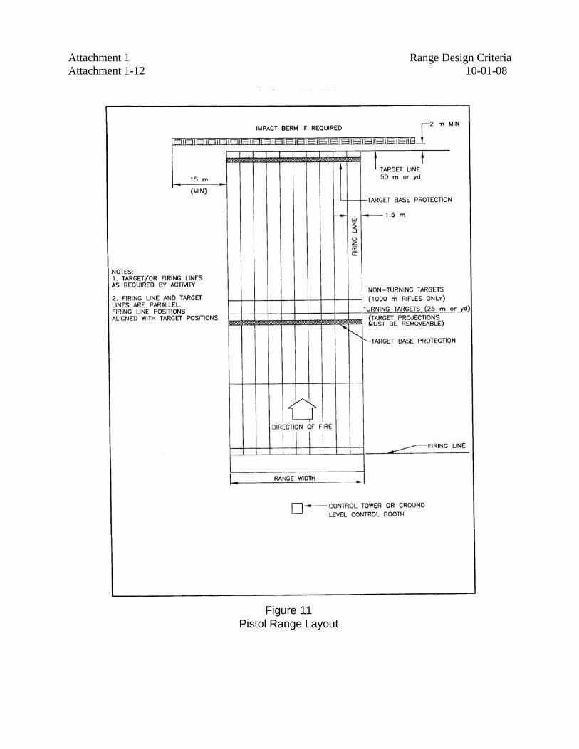
Attachment 1 Range Design Criteria Attachment 1-12 10-01-08
Figure 11Pistol Range Layout
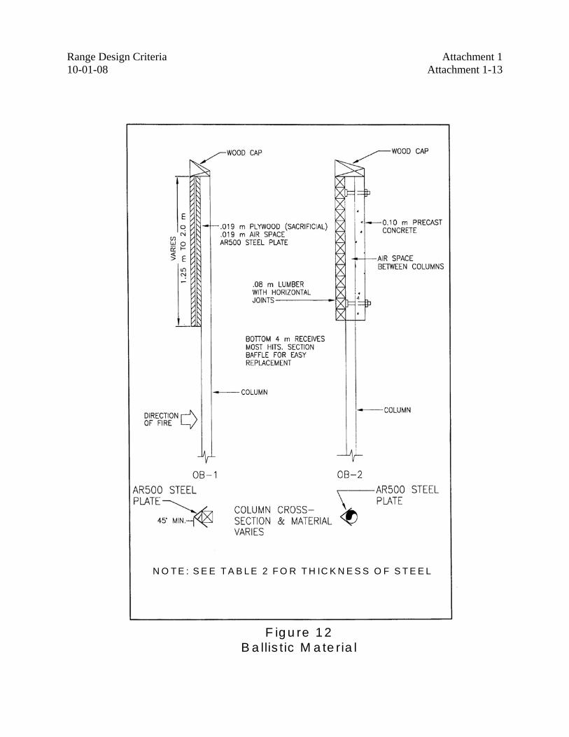
Range Design Criteria Attachment 1 10-01-08 Attachment 1-13
F ig u re 1 2B a llis t ic M a te ria l
N O T E : S E E T A B L E 2 F O R T H IC K N E S S O F S T E E L
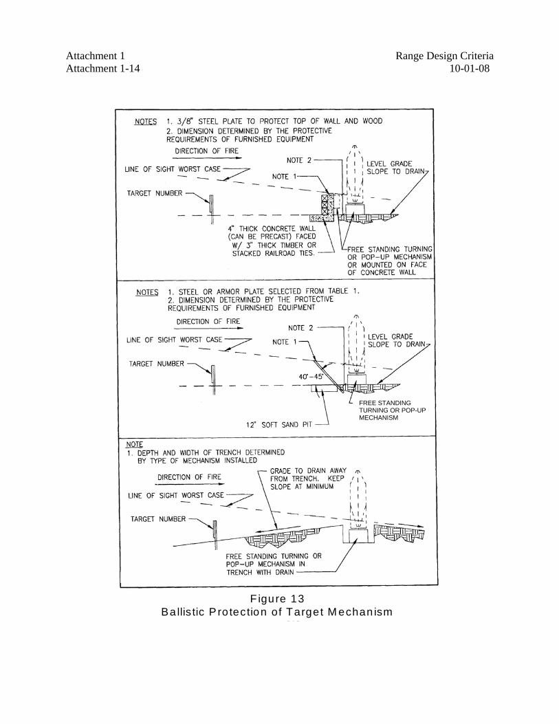
Attachment 1 Range Design Criteria Attachment 1-14 10-01-08
Figure 13Ba llis tic P ro tection of Target M echan ism
FREE STANDING TURNING OR POP-UP MECHANISM
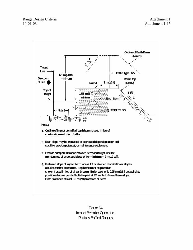
Range Design Criteria Attachment 1 10-01-08 Attachment 1-15
Direction of Fire
Target Line
Top of Target
6.1 m (20 ft) minimum
Note 3
11
1.52 m (5 ft) minimum
Note 4 3 m (10 ft)
0.9 m (3 ft) Rock Free Soil
Earth Berm
1 1/21
39112061.21
Back Stop (Note 2)
Baffle Type 06-5
Outline of Earth Berm (Note 1)
11
Notes:
Outline of impact berm if all earth berm is used in lieu of combination earth berm/baffle.
Back slope may be increased or decreased dependent upon soil stability, erosion potential, or maintenance equipment.
Provide adequate distance between berm and target line for maintenance of target and slope of berm [minimum 9 m (10 yd)].
Preferred slope of impact berm face is 1:1 or steeper. For shallower slopes a bullet catcher is required. Top baffle must be placed as shown if used in lieu of all earth berm. Bullet catcher is 0.95cm (3/8 in.) steel plate positioned above point of bullet impact at 90° angle to face of berm slope. Plate protrudes at least 0.6 m (2 ft) from face of berm.
1.
2.
3.
4.
Figure 14Impact Berm for Open and
Partially Baffled Ranges
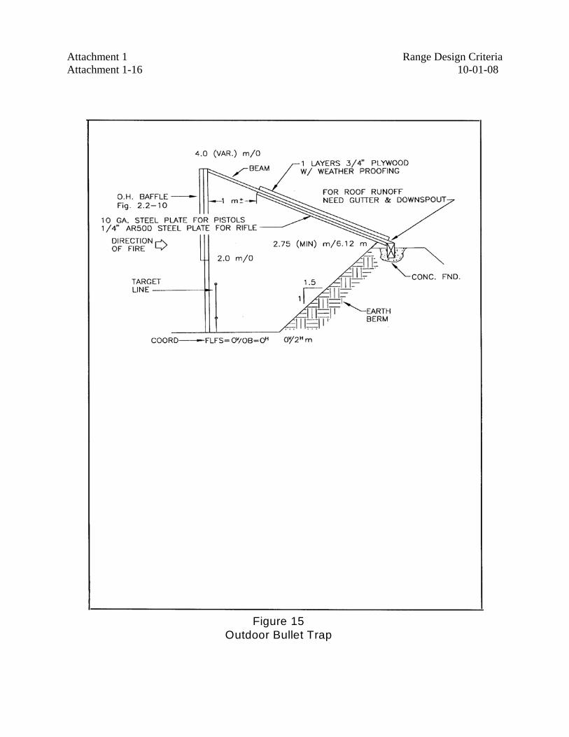
Attachment 1 Range Design Criteria Attachment 1-16 10-01-08
Figure 15Outdoor Bullet Trap
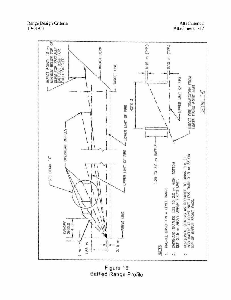
Range Design Criteria Attachment 1 10-01-08 Attachment 1-17
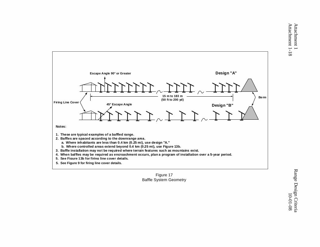
Attachm
ent 1 R
ange Design C
riteria A
ttachment 1-18
10-01-08
39112061.10
Berm
Notes: 1. These are typical examples of a baffled range. 2. Baffles are spaced according to the downrange area. a. Where inhabitants are less than 0.4 km (0.25 mi), use design "A." b. Where controlled areas extend beyond 0.4 km (0.25 mi), use Figure 13b. 3. Baffle installation may not be required where terrain features such as mountains exist. 4. When baffles may be required as encroachment occurs, plan a program of installation over a 5-year period. 5. See Figure 13b for firing line cover details.
45° Escape AngleFiring Line Cover
Design "A"
Design "B"
Escape Angle 90° or Greater
15 m to 183 m (50 ft to 200 yd)
Figure 17Baffle System Geometry
5. See Figure 9 for firing line cover details.
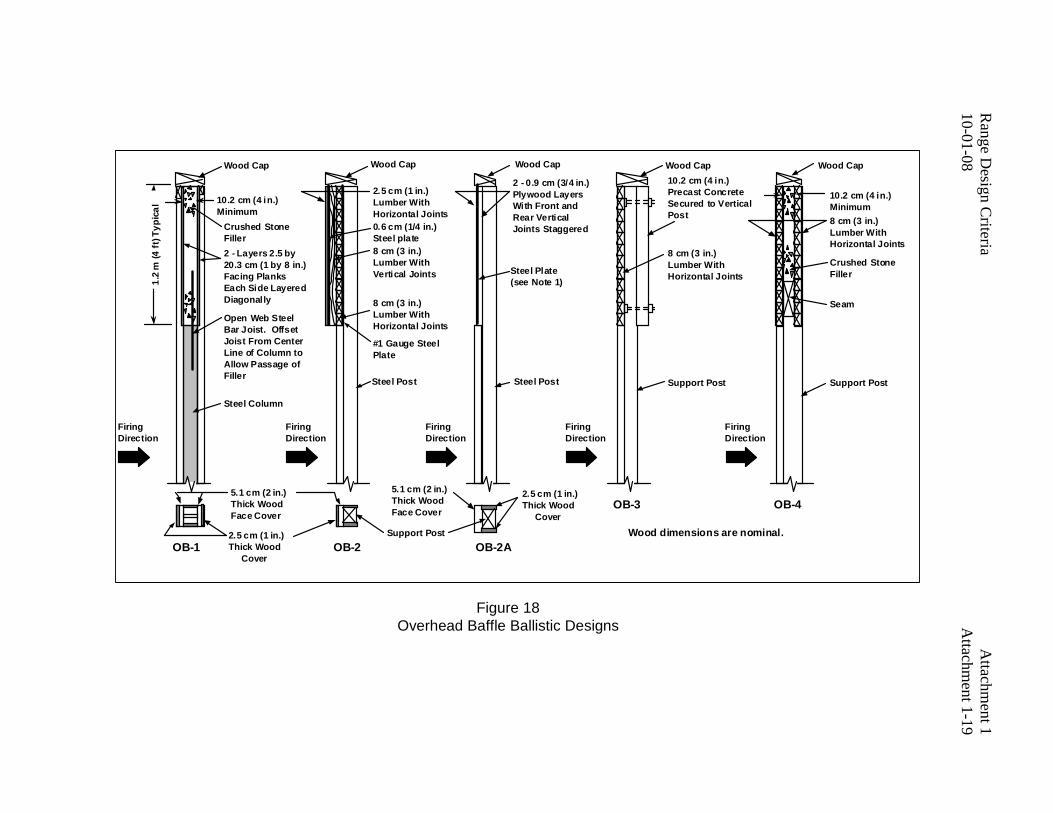
10-01-08
Attachm
ent 1-19R
ange Design C
riteria A
ttachment 1
10.2 cm (4 in.) Minimum
Crushed Stone Filler2 - Layers 2.5 by 20.3 cm (1 by 8 in.) Facing Planks Each Side Layered Diagonally
Open Web Steel Bar Joist. Offset Joist From Center Line of Column to Allow Passage of Filler
Steel Column
Wood Cap
Firing Direction
2.5 cm (1 in.) Lumber With Horizontal Joints0.6 cm (1/4 in.) Steel plate8 cm (3 in.) Lumber With Vertical Joints
8 cm (3 in.) Lumber With Horizontal Joints
2 - 0.9 cm (3/4 in.) Plywood Layers With Front and Rear Vertical Joints Staggered
Steel Plate (see Note 1)
10.2 cm (4 in.) Precast Concrete Secured to Vertical Post
8 cm (3 in.) Lumber With Horizontal Joints
10.2 cm (4 in.) Minimum8 cm (3 in.) Lumber With Horizontal Joints
Seam
Firing Direction
Firing Direction
Firing Direction
Firing Direction
#1 Gauge Steel Plate
Support Post Support Post
39112061.4
OB-1 OB-2 OB-2A
OB-3 OB-4
1.2
m (4
ft) T
ypic
al
Crushed Stone Filler
5.1 cm (2 in.) Thick Wood Face Cover
2.5 cm (1 in.) Thick Wood Cover
Support Post Wood dimensions are nominal.
Steel Post Steel Post
5.1 cm (2 in.) Thick Wood Face Cover
2.5 cm (1 in.) Thick Wood Cover
Wood Cap Wood Cap Wood Cap Wood Cap
Figure 18Overhead Baffle Ballistic Designs
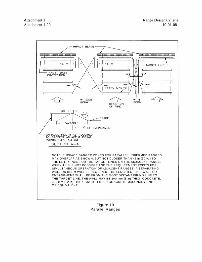
Attachment 1 Range Design Criteria Attachment 1-20 10-01-08
Figure 19Parallel Ranges
NOTE: SURFACE DANGER ZONES FOR PARALLEL UNBERMED RANGESMAY OVERLAP AS SHOW N, BUT NOT CLOSER THAN 45 m (50 yd) TOTHE ENTRY POIN FOR THE TARGET LINES ON THE ADJACENT RANGE.W HEN THIS IS NOT POSSIBLE AND THE REQUIREMENT EXISTS FORSIMULTANEOUS OPERATION OF ADJACENT RANGES, A SEPARATINGW ALL OR BERM W ILL BE REQUIRED. THE LENGTH OF THE W ALL OR EMBANKMENT SHALL BE FROM THE MOST DISTANT FIRING LINE TOTHE TARGET LINE. THE W ALL MAY BE 200 mm (8 in) THICK CONCRETE,300 mm (12 in) THICK GROUT-FILLED CONCRETE MASONARY UNIT,OR EQUIVALENT.
)
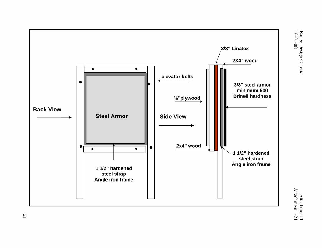
21
Range D
esign Criteria
Attachm
ent 110-01-08
A
ttachment 1-21
Back View Steel Armor
elevator bolts
1 1/2” hardened steel strap
Angle iron frame
3/8” steel armor minimum 500
Brinell hardness
Side View
½”plywood
2x4” wood
3/8” Linatex
2X4” wood
1 1/2” hardened steel strap
Angle iron frame
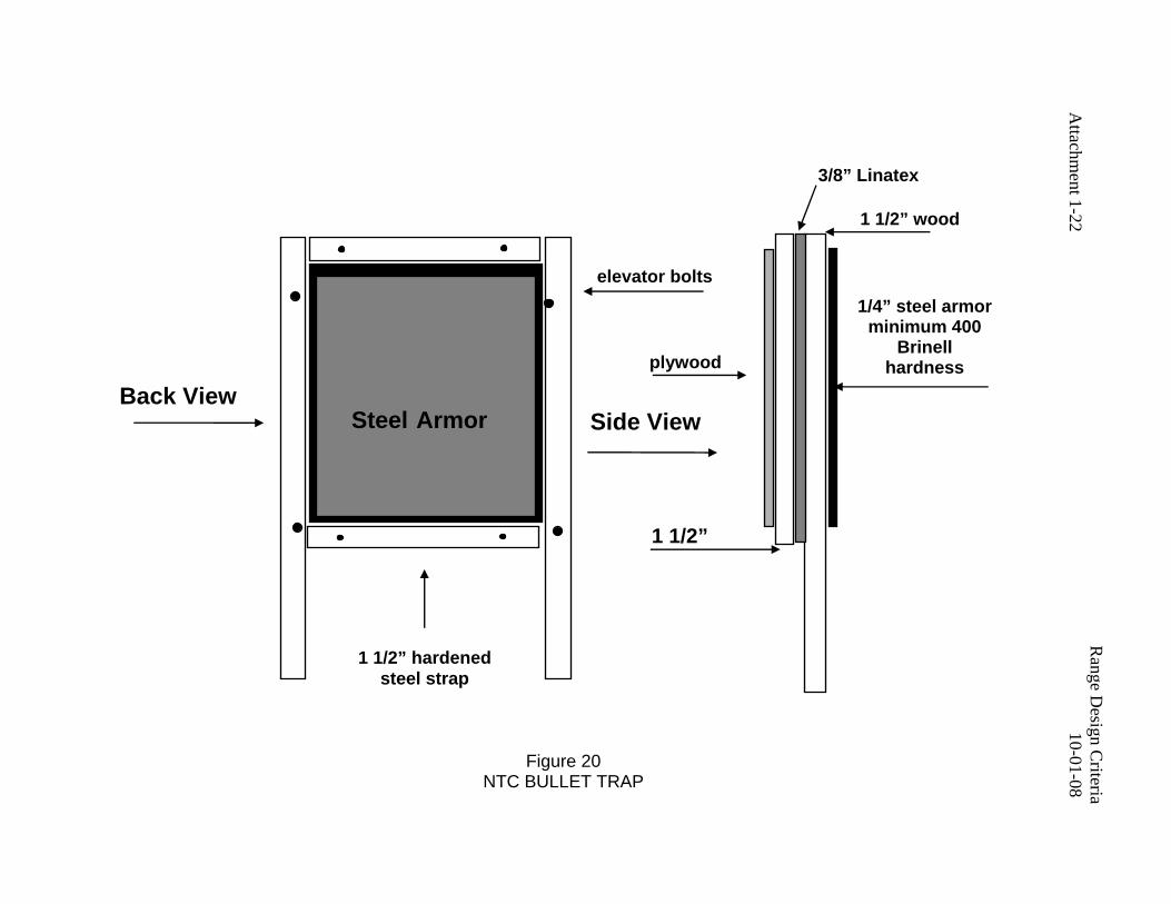
Attachm
ent 1 R
ange Design C
riteriaA
ttachment 1-22
10-01-08
Back View Steel Armor
elevator bolts
1 1/2” hardened steel strap
1/4” steel armor minimum 400
Brinell hardness
Side View
plywood
1 1/2”
3/8” Linatex
1 1/2” wood
Figure 20 NTC BULLET TRAP