rammed earth structures – code of … tc 1/sc 5/cd sazs 724 ii contents page rammed earth...
TRANSCRIPT

SADCSTAN TC 1/SC 5/CD SAZS 724
SADC HARMONIZED STANDARD FOR
RAMMED EARTH STRUCTURES – CODE OF PRACTICE
THC 03

SADCSTAN TC 1/SC 5/CD SAZS 724
i
LOCAL FOREWORD
This Standard SADC ZW HS 983:2014: Rammed earth structures – Code of practice, is the national adoption of Southern African Development Community Cooperation in Standardization’s (SADCSTAN) regional standard. This standard replaces ZWS 724:2000 which is now withdrawn. The SADCSTAN membership is open to National Standards Bodies (NSBs) of SADC Member States, or where a NSB has not been established by a Member State, any other institution designated by its Minister responsible for industry and trade. The Standards Association of Zimbabwe being the national standards body is a member of SADCSTAN. SADCSTAN promotes the coordination of standardization activities and services in the region with the purpose of achieving harmonization of standards and technical regulations (with the exception of legal metrology regulations) in support of the objectives of the SADC Protocol on trade. Zimbabwe’s participation in the development of this regional standard was through the Standards Association of Zimbabwe’s Technical Committee (TC) BC 042: Rammed Earth Structures, on which the following interests were represented: University of Zimbabwe, Department of Civil Engineering Civic Forum (Housing People of Zimbabwe) Construction Industry Federation of Zimbabwe Institute of Architects of Zimbabwe Intermediate Technology Development Group John Sisk and Son Julian Keable and Partners Ministry of National Housing and Social Amenities Ministry of Transport Infrastructural Development Scientific and Industrial Research and Development Centre Standards Association of Zimbabwe Zimbabwe Association of Consulting Engineers Rammed Earth Consulting CIC

SADCSTAN TC 1/SC 5/CD SAZS 724
ii
Contents Page
RAMMED EARTH STRUCTURES — CODE OF PRACTICE ................................................................... 1
1 Scope .................................................................................................................................................... 1
2 References and abbreviations ............................................................................................................ 1
2.1 Normative references ....................................................................................................................... 1
2.2 Abbreviations .................................................................................................................................... 1
2.3 Terms and definitions ....................................................................................................................... 1
SECTION 1 - MATERIALS ....................................................................................................................... 2
3 Soil ........................................................................................................................................................ 2
4 Water .................................................................................................................................................... 2
4.1 Quality of water ................................................................................................................................. 2
4.2 Optimum moisture content (OMC) ................................................................................................... 2
5 Mixing and blending ............................................................................................................................ 2
6 Stabilization ......................................................................................................................................... 2
SECTION 2 - FORMWORK ...................................................................................................................... 3
7 Formwork requirements ...................................................................................................................... 3
8 Formwork in use .................................................................................................................................. 3
SECTION 3 - GROUNDWORKS .............................................................................................................. 3
9 Foundations ......................................................................................................................................... 3
10 Rising damp protection for walls ...................................................................................................... 5
11 Floors ................................................................................................................................................. 5
SECTION 4 - SUPERSTRUCTURE.......................................................................................................... 6
12 Compressive strength of walls ......................................................................................................... 6
12.1 Guide ............................................................................................................................................... 6
12.2 Average compressive strength ...................................................................................................... 6
13 Density of walls .................................................................................................................................. 6
13.1 Guide ............................................................................................................................................... 6
13.2 Dry density ...................................................................................................................................... 7
14 Water absorption of walls ................................................................................................................. 7
14.1 Guide ............................................................................................................................................... 7
14.2 Recommended standard practice .................................................................................................. 7
15 Weather erosion of walls ................................................................................................................... 7
15.1 Guide ............................................................................................................................................... 7
16 Visual test of walls ............................................................................................................................. 9
16.1 Guide ............................................................................................................................................... 9

SADCSTAN TC 1/SC 5/CD SAZS 724
iii
SECTION 5 - STABILITY ....................................................................................................................... 11
17 Stability of walls: Slenderness........................................................................................................ 11
17.1 Guide ............................................................................................................................................. 11
18 Stability of walls: Openings and lintels .......................................................................................... 11
18.1 Guide ............................................................................................................................................. 11
18.3 Deemed to satisfy ......................................................................................................................... 13
18.4 Arches ........................................................................................................................................... 15
19 Stability of walls: Bonding .............................................................................................................. 16
19.1 Guide ............................................................................................................................................. 16
19.2 Joints ............................................................................................................................................. 16
SECTION 6 - DETAILS AND FINISHES ................................................................................................ 17
20 Fixings and ties ................................................................................................................................ 17
20.1 Guide ............................................................................................................................................. 17
20.3 Deemed to satisfy ......................................................................................................................... 18
21 Surface treatments .......................................................................................................................... 19
21.1 Guide ............................................................................................................................................. 19
21.2 Surface finishes ............................................................................................................................ 19
21.3 Renders ......................................................................................................................................... 21
21.4 Surface treatments ....................................................................................................................... 23
22 Service inserts ................................................................................................................................. 24
22.1 Guide ............................................................................................................................................. 24
22.2 Holes through walls ...................................................................................................................... 25
23 Walls, floors and health ................................................................................................................... 26
ANNEX A .................................................................................................................................... 27 The 'roll' test .............................................................................................................................. 27
A.1 Purpose ........................................................................................................................................... 27
A.2 Procedure ....................................................................................................................................... 27
A.3 Result .............................................................................................................................................. 27
ANNEX B .................................................................................................................................... 28 'Drop' test .................................................................................................................................. 28
B.1 Purpose ........................................................................................................................................... 28
B.2 Procedure ....................................................................................................................................... 28
ANNEX C .................................................................................................................................... 30 The formwork deformation test ................................................................................................ 30
C.1 Purpose ........................................................................................................................................... 30
C.2 Procedure ....................................................................................................................................... 30
C.3 Deemed to satisfy........................................................................................................................... 30

SADCSTAN TC 1/SC 5/CD SAZS 724
iv
ANNEX D .................................................................................................................................... 32 The compressive strength test ................................................................................................ 32
D.1 Purpose ........................................................................................................................................... 32
D.2 Procedure ....................................................................................................................................... 32
ANNEX E .................................................................................................................................... 33 The wall density test (See also the compressive strength test in Annex D) ......................... 33
E.1 Purpose ........................................................................................................................................... 33
E.2 Procedure ....................................................................................................................................... 33
ANNEX F .................................................................................................................................... 34 Erosion test (pressure spray method) ..................................................................................... 34
F.1 General ............................................................................................................................................ 34
F.2 Procedure ........................................................................................................................................ 34
F.3 Results ............................................................................................................................................ 34
F.4 Penetration of moisture.................................................................................................................. 35
F.5 Surface coatings ............................................................................................................................. 35
ANNEX G.................................................................................................................................... 36 Erosion test (Geelong method) ................................................................................................ 36
G.1 General ........................................................................................................................................... 36
G.2 Measurement of pit depth .............................................................................................................. 37
G.3 Surface coatings ............................................................................................................................ 37
G.4 Moisture penetration ...................................................................................................................... 37
G.5 Results ............................................................................................................................................ 37
ANNEX H .................................................................................................................................... 39 Render adhesion test ................................................................................................................ 39
H.1 Purpose ........................................................................................................................................... 39
H.2 Procedure ....................................................................................................................................... 39

SADCSTAN TC 1/SC 5/CD SAZS 724
v
Foreword This text is a Southern African Development Community Draft Harmonized Text (SADCSTAN DHT) covering requirements on the design, construction and test methods for rammed earth structures. The harmonization of standards and technical regulations in the SADC region is an obligation under the SADC Trade Protocol which is aimed at elimination of non-tariff barriers to trade within the region to enhance economic development and establishment of a free trading bloc.

SADCSTAN TC 1/SC 5/CD SAZS 724
vi
Introduction Ramming earth has been a method of construction used for centuries in various parts of the world, and is commonly known by its French name 'Pise'. Earth is extracted from the ground and compacted in layers inside specially constructed formwork. After compaction the formwork is released and moved along to a new position in the wall or upwards to the next layer. In this way the building goes up rapidly, layer by layer, row by row. This technique can produce buildings that are strong, durable safe and desirable. Above all, because earth is an abundant and cheap resource, rammed earth buildings are very economical; in addition the majority of the investment goes directly into the local economy. The method has an essential simplicity, and with its unskilled labour intensity, rammed earth can be seen as a valuable tool in the generation of low-cost housing in developing countries in both urban and rural areas. If well-built, rammed earth (RE) walls will compare favourably with other masonry materials, such as burnt clay bricks or concrete blocks, in compressive strength, erosion by moisture or seasonal changes of dimension. Costs will also, in most cases, be highly competitive. It must be remembered, though, that 'earth' varies in quality just as bricks or concrete blocks do. Standards of comparison are needed. This code of practice does not cover blocks made of earth. To achieve comparable standards using earth blocks, a greater degree of production and site control is needed than with RE. Mature topsoil, useful for growing plants, should not be used-throughout this Code of Practice soil means subsoil, and earth also means subsoil. Nowadays, the selection and testing of soils for building can be done with some precision, and there are good techniques available to stabilize or protect earth walls from water damage and shrinkage. This document aims to show that, with adequate control and protection, buildings built in rammed earth can achieve high standards. The document will set down definitive standards by which rammed earth buildings and building techniques can be judged. The document can be used by: a) local builders to show the basic standards that will achieve long-lasting results; b) larger contractors and designers as an outline specification for rammed earth; c) official building regulators to show how to judge the suitability for any rammed earth structures under their control ; d) loan and aid agencies to give assurance on durability/mortgageability.
SADCSTAN TC 1/SC 5/CD SAZS 724
1
RAMMED EARTH STRUCTURES — CODE OF PRACTICE 1 Scope This code of practice gives guidance on the design, construction and test methods for rammed earth structures.
2 References and abbreviations 2.1 Normative references The following referenced documents are indispensable for the application of this document. For dated references, only edition cited applies. For undated references, the latest edition of the referenced document (including any amendments) applies. EN 197-1, Cement - Part 1: Composition, specifications and conformity criteria for common cement. NZS 4298, Materials and workmanship for earth buildings. ZWS 162, Structural use of timber - Part 1: Limit states design. ZWS 162, Structural use of timber - Part 2: Allowable stress design. ZWS 170, Structural use of concrete - Part: Code of practice for design and construction. ZWS 185, Methods of testing soils for civil engineering purposes - Part 1: Preparation, classification and density of soils.
2.2 Abbreviations For the purposes of this document, the following abbreviations apply: DPC: Damp proof course. DPM: Damp proof membrane. LCE: Light Compactive Effort OMC: Optimum moisture content.
2.3 Terms and definitions Efflorescence: powdery crystals, on the brick surfaces. It is usually white. Fretting: that is loss of layers of soil either upon wetting or after drying.

SADCSTAN TC 1/SC 5/CD SAZS 724
2
SECTION 1 - MATERIALS 3 Soil Soil used to form rammed earth structures should be free from organic material and other non-soil substances, such as rubbish, deleterious material, etc. Soils for rammed earth should have 50% to 70 % (can be achieved by blending see clause 5) fine gravel and sand, 15% to 30 % silt and 5% to 15% clay. Soil mixtures should be tested by the 'roll' method, and the break off should be between 80 mm and 120 mm (see Annex A). NOTE Deleterious material in this context means soil containing salts such as sulphates which interfere with the setting of the binder.
4 Water 4.1 Quality of water Water used for ramming should be from a clean source. It should be free from organic material and any other harmful substances.
4.2 Optimum moisture content (OMC) The OMC is important because it has a direct bearing on the strength of the finished wall. With too little water the soil cannot be properly squeezed, with too much it becomes too wet and the water itself resists compaction. The ideal amount of water will vary from one soil mix to another. Fortunately, once some experience in ramming has been gained, it becomes quickly obvious when the soil is too wet or dry. The mix of materials for use in rammed earth structures should have the 'optimum moisture content', according to the 'drop' test (see Annex B).
5 Mixing and blending Soils should be well mixed prior to ramming, if: e) there is more than one source of soil to be rammed; f) stabilizers are to be added; g) additional water is required to achieve OMC. Mixing by hand or by mechanical mixer should continue until there is uniform distribution of materials with uniform colour and consistency.
6 Stabilization Stabilizing materials may be added to earth for rammed earth structures to improve strength, to improve resistance against water, or to achieve less shrinkage. Approved materials for stabilization are: a) ordinary Portland cement - see EN 197-1; b) lime or hydrated lime; c) lime combined with pozzolanas such as pulverized fuel ash and ground granulated blast furnace slag;
d) cement extended with pozzolanas such as pulverized fuel ash and ground granulated blast furnace slag. e) such other stabilizer as approved by the building supervisor.

SADCSTAN TC 1/SC 5/CD SAZS 724
3
SECTION 2 - FORMWORK 7 Formwork requirements Formwork should allow access to all parts within the formwork for compaction. Soil should be placed within the formwork and then rammed until it is fully compacted, so as to meet the requirements of the wall density test. (See 13.2)
8 Formwork in use Deformation of formwork: main elements (sides, end stops and corners) should not exceed 3 mm from the true position when tested by applying a 150 kg load at mid-span between ties or supports (see Annex C). Care should be taken when removing the formwork not to damage the work.
SECTION 3 - GROUNDWORKS 9 Foundations Material for rammed earth foundations and any walls below damp proof course level should be of masonry complying with the requirements of the applicable building by-laws or stabilized rammed earth if protected from dampness. Compressive strength and density should comply with Section 4 requirements. Foundation strips in rammed earth should be at least as thick as the wall above, and otherwise have the dimensions in Table 1.

SADCSTAN TC 1/SC 5/CD SAZS 724
4
TABLE 1 – MINIMUM WIDTH OF STRIP FOUNDATIONS IN RAMMED EARTH
Type Of Subsoil
Condition Of Subsoil
Field Test Applicable
Foundation Width
Foundation Thickness
I
rock
not inferior to sandstone, limestone or firm chalk
requires at least mechanically operated pick for excavation
equal to width of wall
not applicable (N/A)
II
gravel
sand
dense dense
requires pick for excavation. wooden peg 50 mm square hard to drive beyond 150 mm
equal to width of wall
N/A
III
clay
sandy clay
stiff stiff
cannot be moulded with the finders and requires a pick or mechanically operated spade for the removal
400 mm
or wall width, whichever is larger
IV
clay
sandy clay
firm firm
can be moulded by firm pressure with the fingers and can be excavated with spade
500 mm
or wall width, whichever is larger
V
sand
silty sand
clayey sand
loose loose loose
can be excavated with a spade. wooden peg 50 mm square can be easily driven
so better to dig deeper to firmer subsoil then apply width needed for that soil type
VI
silt
clay
(and sandy/silty clays)
soft soft
fairly easily moulded in the fingers and readily excavated
so dip deeper to firmer subsoil
VII
silt
clay
(and sandy/silty clays)
very soft very soft
natural sample in rainy season exudes between fingers when squeezed in fist
so dig deeper to firmer subsoil
NOTE 1 F is the foundation width. W is the wall width.
NOTE 2 An engineered foundation design may be used.
SADCSTAN TC 1/SC 5/CD SAZS 724
5
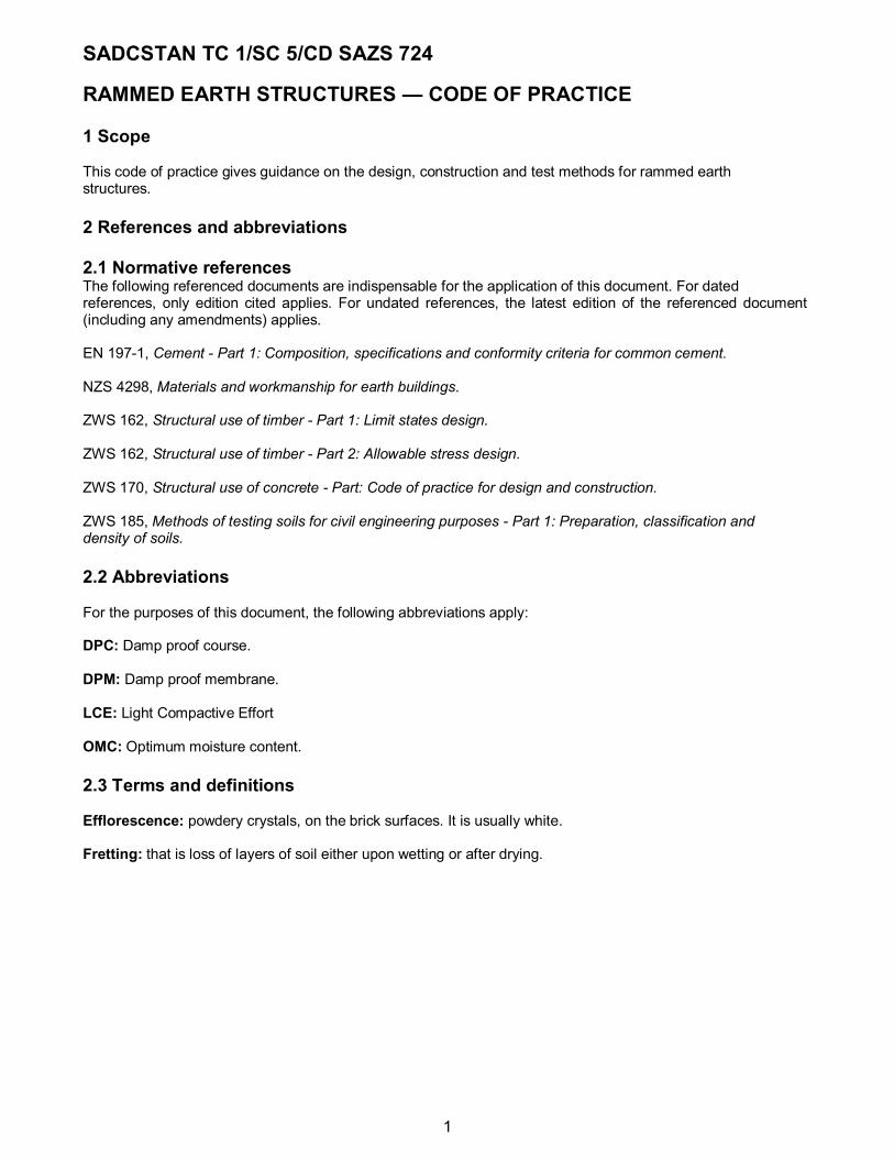
10 Rising damp protection for walls Rammed earth walls should be constructed so as to prevent moisture from the ground rising up and into the building (see Figure 1).
11 Floors 11.1 Rammed earth floors should be protected from rising damp so that damp does not penetrate the building (see Figure 1).
FIGURE 1 – RISING DAMP PROTECTION FOR WALLS
11.2 If floors will be washed, the floor surface should be waterproofed, and the junction of floor and walls should be protected with a suitable raised skirting. Floor levels should be at least 150 mm above surrounding area, and 300 mm in areas of high and intensive rainfall (over 1 000 mm a year) or where the ground water level is within 750 mm of the surface (see Figure 2).

SADCSTAN TC 1/SC 5/CD SAZS 724
6
FIGURE 2 – DAMP PROTECTION FOR FLOORS
SECTION 4 - SUPERSTRUCTURE 12 Compressive strength of walls 12.1 Guide Rammed earth can achieve high levels of compressive strength usually without the need for stabilization. In some cases it may be necessary to adjust the mix of materials in the earth. Too much clay in the soil will increase its compressibility, too little will prevent it binding. In some cases it may be necessary to add stabilization to the soil (see clause 6). An important factor in achieving the maximum possible compressive strength is ensuring the maximum dry density in the material. This is controlled by obtaining the optimum moisture content (see clause 4). The drop test (see Annex B), should be repeated whenever there is a new soil source, or a new work-gang, or change of weather.
Other factors in improving good strength are ensuring that the initial material is well mixed (see clause 6) and that good ramming and formwork techniques are used (see Section 2).
12.2 Average compressive strength Rammed earth walls should be tested for compressive strength. The average compressive strength should not be less than 1.5 N/mm
2 generally, or 2.0 N/mm
2 for walls of height between 3.0 m and 6.0 m at a minimum age
of 7 days.
13 Density of walls 13.1 Guide The density of the material is an important indicator of the strength and durability of the finished wall. Maximum dry density is achieved when the material rammed is at OMC. Density requirement assumes normal dense aggregates. Aerated materials such as pumice (volcanic material) would not achieve the recommended density, though its strength might be adequate when tested

SADCSTAN TC 1/SC 5/CD SAZS 724
7
for compression.
13.2 Dry density The dry density (pd) of the rammed earth walls should be >95 % of LCE maximum dry density (see clause 15 of ZWS 185, Part 1:1997). See Annex E.
14 Water absorption of walls 14.1 Guide The effect of water on earth walls is to break the bonds between particles, thus lowering crushing strength. Protection from water absorption is important for the durability of the wall. Wherever groundwater may occur (even if infrequently) then protection at the base should be given by a damp-proof course (see clause 10). Protection at the top should be given by a roof or capping (see clause 15). Water absorption can be lowered by a good mix of soil, good compaction and optimum moisture when ramming. Stabilization of the soil can be used to improve poor water absorption results (see clause 15). An alternative approach is to protect the wall with a surface treatment. Various types of renderings are discussed in more detail in clause 20.
14.2 Recommended standard practice Walls should be protected from excessive water absorption at the base, the top, and the face according to clauses 10, 15 and 21.
15 Weather erosion of walls 15.1 Guide Earth walls may be eroded at their surface by driving rain, which can loosen the smaller particles. This may happen during or after construction. Walls will perform better when a good soil mix is used (see clause 3) and the soil well compacted (see clause 8) at optimum moisture content (see clause 5). Always ensure 'a good hat, boots and a coat' for long life (see Figure 3).

SADCSTAN TC 1/SC 5/CD SAZS 724
8
FIGURE 3 – EROSION PROTECTION FOR WALLS 15.1.1 A good hat Walls will be protected by deep overhangs. This point is very important indeed. It is a false economy to build only a small overhang. Significant protection will be given to a depth below overhang of three times the projection, where wind conditions are not severe. Of course, the roof itself must not leak. 15.1.2 Boots The base of walls will be worn by splashback of rain, if not protected. Protection from rain-splash onto the base of the wall, but over the DPC, should be given. This is a vital point, especially for unstabilized soil (see Figure 1). There are two ways of approach: 15.1.2.1 A resistant surface may be given by a render, by using bricks or stone, or by building the lower part of the wall using a stabilizer, even if the upper part will be plain soil. 15.1.2.2 A 'sacrificial' layer may be added, and replaced when it has worn. The cheaper approach of using an extra layer of soil which will be eroded by the rain-splash, and then replaced, is effective provided it is maintained. 15.1.3 Coat The main surface can either be coated or built to withstand driving rain. Various types of coatings and renderings are discussed in more detail in clause 20. Stabilization is another approach to poor weather erosion results, which can be dramatically improved (see clause 6). It is possible to allow walls with poor erosion standards when a high degree of building maintenance can be expected. In some areas, wind scour, the effect of wind-driven sand particles removing the surface fines (much as driving rain can do), will occur, if no protection is given (see clause 15.1.2).
15.2 Rammed earth walls exposed to weather should be tested (including any surface treatment proposed)
SADCSTAN TC 1/SC 5/CD SAZS 724
9
using the erosion test (pressure spray method or the erosion test method). See Appendices F and G.
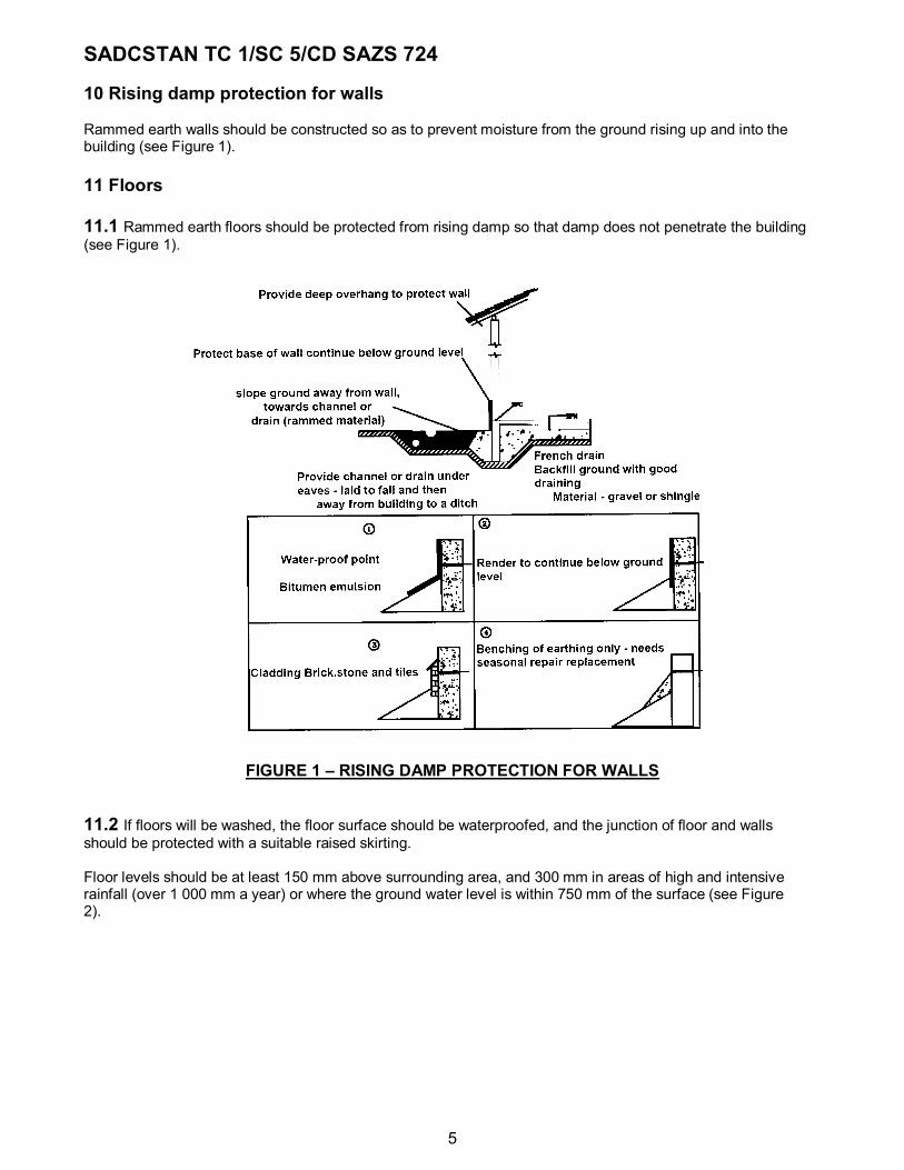
16 Visual test of walls 16.1 Guide Corners and exposed edges should be protected from wear either by putting a triangular fill in the formwork (to produce a chamfered corner) or by building up the corner using concrete wedges, or stone/brick. Honeycombing is caused in a number of ways:
i) oversized gravel next to formwork (work gravel away from sides of formwork using a space, before ramming - this is called 'padding');
ii) poorly mixed soil (mix better); iii) too little clay to permit compaction (change soil composition); iv) water content not correct (too little/too much).
Joint cracks and construction holes should be filled soon after construction, unless it is planned to render the wall, in which case holes will act as 'key' for the render. Shrinkage cracks may be caused by high clay content in the soil. It can be reduced by reducing the clay content: stabilization will also reduce shrinkage. Lime and pozzolanic mixtures work well with clay (see clause 6). Slow down the drying out of the wall, especially when working in hot, clear sunshine:
i) keep the wall surface damp by lightly spraying with water;
ii) shade the wall, for example, use plaited grass or palm leaf screens. This applies to new rendering too.
16.2 Walls should be free of broken edges and honeycombing (see Figure 4). Joint cracks, construction holes and holes caused by striking formwork should be filled using compatible material within 24 hours of their appearance, or the wall rendered.
Shrinkage cracks should not be more than 3 mm wide and 75 mm in length, and be limited to twenty in any square metre. All shrinkage cracks should be made good or the wall rendered.
SADCSTAN TC 1/SC 5/CD SAZS 724
10
FIGURE 4 – BROKEN EDGES AND HONEYCOMBING

SADCSTAN TC 1/SC 5/CD SAZS 724
11
SECTION 5 - STABILITY 17 Stability of walls: Slenderness 17.1 Guide Cement stabilized rammed earth walls can be built with thinner walls because they can resist bending forces to a slightly greater extent. Because ramming often takes place with a man standing between the two sides of the formwork, a minimum wall width of 300 mm should be used.
17.2 The slenderness ratios for rammed earth walls should meet the limits in Table 2 and in no case should walls be less than 300 mm thick.
TABLE 2 – SLENDERNESS RATIOS FOR RAMMED EARTH WALLS
Maximum length (m)
Restraint Stabilized Ratio: (Width: height)
9 9 9 9
unrestrained
unrestrained
restrained
restrained
unstabilized
cement stabilized
unstabilized
cement stabilized
1:8
1:10
1:12
1:16
NOTE A restrained wall is one that is at least bonded by lapping alternate courses to a return wall and/or pier of not less than 450 mm length, at both ends; or better where the return wall is, built continuously with it. Walls may be stepped in as they rise in height, provided that the slenderness ratio for the wall above still meets the requirements of Table 2 (see Figure 5).
18 Stability of walls: Openings and lintels 18.1 Guide Openings will weaken the wall in which they are placed, and will need to support any loads placed on top of them. This guide first discusses what materials may be used over the opening, then adds general construction points. 18.1.1 Timber lintels The size of timber required for openings depends on the species and standard of timber. The timber should be designed to comply with ZWS 162: Part 1 or 2. Timber lintels should be protected from attack from both water (leading to rot), wood boring insects and termite attack if the species is not naturally resistant. NOTE Reinforced concrete lintels are preferable.

SADCSTAN TC 1/SC 5/CD SAZS 724
12
FIGURE 5 - STABILITY OF WALLS
18.1.2 Reinforced concrete lintels (RC lintels) RC lintels can either be precast or cast in situ. Bars should be secured in place at the time of pouring concrete. The RC lintels should be designed to comply with ZWS 170: Part 1.
18.2 The number, size or position of openings or recesses in a rammed earth wall should not be such as to impair the stability of the walls. Lintels over openings and recesses in rammed earth walls should be of suitable strength to carry the

SADCSTAN TC 1/SC 5/CD SAZS 724
13
superstructure above them. Lintel bearings should not be less than 200 mm beyond the opening (see Figure 6). Openings can occur with no lintel when the openings extend up to the roof plate (provided the plate is able to carry any load placed on it), or when an arched opening is used.
18.3 Deemed to satisfy Openings in any wall should not constitute more than half of the length of the wall (see Figure 6), and, where the distance between the openings is less than their width, lintels should be made continuous over the series (see Figure 6). The minimum distance of 600 mm between openings with separate lintels should be 600 mm (see Figure 6). No lintel is required if: a) there is no wall over the opening (opening reaches plate); b) the head is arched (circular or pointed); (see Figure 6).
i) with minimum 450 mm of wall above the crown;
ii) openings are limited to 1 000 mm wide;
iii) the rise from the base to the crown of the arch (whether pointed or curved) is not less than half the opening width;
iv) care is taken in formwork to support ramming loads (usually a 'blockout' will be needed – see Section
2).

SADCSTAN TC 1/SC 5/CD SAZS 724
14
FIGURE 6 – OPENINGS AND LINTELS

SADCSTAN TC 1/SC 5/CD SAZS 724
15
FIGURE 6 (Concluded)
18.4 Arches Unreinforced arches can be used successfully in earth walls, so long as they comply with provisions given in 18.3. Arches help in the transfer of loads. Avoid the use of steel and the risk of rust in humid areas. If span exceeds 1 000 mm, lintels or arches should be calculated in accordance with ZWS 170: Part 1 (see Figure 6). Openings can be planned outside the limits of 18.3 if it can be shown that the wall is still stable. Generally, it is the unbuttressed piers between openings that are the weak points; these piers can be reinforced or upgraded with stabilization. Reinforcement in the wall over and near openings will improve the stability and help strengthen the piers and corners. Ensure that the loads from trusses, beams or rafters are always spread by plates (timber, steel or concrete). Ensure that lintels have sufficient bearing each end (200 mm required).

SADCSTAN TC 1/SC 5/CD SAZS 724
16
19 Stability of walls: Bonding 19.1 Guide There are two ways to move formwork: sideways and upwards (see Section 2). The way to bond sections of wall together will depend partly on which formwork method is to be used. 19.1.1 Sideways movement of formwork normally requires bonded joints similar to block or brick masonry walling; think of each 'cast' (one form fully rammed) as a block. The weakest point will be at the corner where the overlap will be limited to the wall thickness this is why formwork which permits corners to be rammed in one piece is recommended. See Figure 7. 19.1.2 Round the corner formwork will improve the bonding at corners, but remember that the 'L-shaped' form needed for this should allow one longer and one shorter leg, so that the next course can be reversed to give an overlapping bond (see Figure 7). 19.1.3 Upwards movement of formwork requires a positive interlocking joint between each panel, with at least 25 mm, but preferably 50 mm, offsets or rebates (see Figure 7). Internal walls should be bonded to external walls or piers.
19.2 Joints Rammed earth walls should be built so that the individual sections of wall bond with the rest of the wall by staggering joints not less than the thickness of the wall. Exemption: vertical joints in wall sections are permitted if: foundations are in reinforced concrete or if adjacent sections interlock on plan by a minimum of 25 mm.

SADCSTAN TC 1/SC 5/CD SAZS 724
17
FIGURE 7 - BONDING
SECTION 6 - DETAILS AND FINISHES 20 Fixings and ties 20.1 Guide Holes can be made in rammed earth. Where the roof is lightweight, wind uplift may be greater than the roof weight, so fixing down the roof members is important. The ties need to be well buried in the wall, making use of the wall weight. Good detailing in joinery avoids many problems. Avoid doors and windows pivoting on a corner of the wall and thus straining the hinges: if doors and windows are mounted either at or on the face of the wall they will have less risk of damage. Alternatively, door, shutter or window stops may be provided. The use of standard frame anchors is satisfactory. The use of metal fixed frames will help in securing moving parts, and will not be attacked by termites; doors and

SADCSTAN TC 1/SC 5/CD SAZS 724
18
windows in constant use should also be free from attack. When using metal it should be protected from corrosion using an approved manner such as galvanising.
20.2 Roofs should be anchored to secure them against the expected wind forces. Large items of joinery, such as doors and windows, and other heavy objects to be fixed to rammed earth walls, should be fixed securely and in such a way as not to damage the wall.
20.3 Deemed to satisfy Roof frame and/or wall plates (or timber ring-beams) should be anchored at 900 mm centres using: a) two strands of eight gauge minimum galvanized wire, secured to plates and built 450 mm minimum depth
into the wall, using 150 mm long anchors at the bottom (see Figure 8);
b) one galvanized or non-ferrous metal strip, minimum 25 mm x 2 mm, secured to plates and built into wall 450 mm minimum, using 150 mm long anchors at the bottom (see Figure 8);
c) such other anchor as the building inspector should approve.
FIGURE 8 - FIXINGS

SADCSTAN TC 1/SC 5/CD SAZS 724
19
21 Surface treatments (See Figure 9) 21.1 Guide Most earth walls, even stabilized walls may benefit from surface treatments. Renders may be used externally or internally. The reasons for adding a surface can be any of the following: waterproofing; resistance to wear; reduction in vermin hiding places, thus improved health; reduced maintenance; reduction in heat-gain by reflection; ease of surface cleaning; improved appearance. Reasons against adding a surface include: extra cost (acceptance of continuing maintenance); suitable materials not available; process is more complicated (skills may not be available). Rammed earth walls, if well made, can withstand a certain amount of rain, provided this cannot settle on the top of any surface (such as sills). However, with time, the smallest particles will be washed out, leaving a roughened surface. With ideal soils and good workmanship such a wall will last long, but otherwise further wear will follow. Thus a surface treatment which will bind the particles in place is useful, but render finishes are not specifically required if the finished wall meets the recommended standard practice without them.
21.2 Surface finishes 21.2.1 Lime-wash (whitewash) Lime-wash has traditionally been used by many builders as a surface finish and this remains a good solution. The lime-wash will need periodic renewal, ideally each year. 21.2.2 Polymer emulsion (PVA) Polymer emulsion is a newer product (not emulsion paint, but similar to white wood glue) which can be applied by brush or, better still, by spray - a backpack or stirrup-pump can be used. PVA can be used at a range of different dilutions in water; it is useful in helping adhesion of renders, or may be used as the finishing coat where a transparent coating (exposing the appearance of the soil) is wanted. A solvent-based system of acrylic sealer is recommended for walls facing extremes of wind-driven rain. 21.2.3 Bitumen emulsion Bitumen emulsion such as road-builders use (e.g. Colas) is another approach (where a painted or 'tyrolean' finish will be applied). This should not be applied when the wall is still in the early stages of drying out, as the

SADCSTAN TC 1/SC 5/CD SAZS 724
20
bitumen will not adhere and be 'thrown off the wall surface. 21.2.4 Emulsion paint Emulsion paint will be absorbed if used alone, but can be used if mixed with sand which is then 'thrown' over a base coat of bitumen emulsion while the base coat is still tacky. 21.2.5 Oil paint Below are good practice details when applying oil paint: remember that an earth wall will suck in anything soluble; penetration of paint is not helpful to durability, so avoid primers that penetrate walls. walls should be thoroughly dry and brushed with a broom; use paint with at least 88% linseed oil in the carrier and which ideally has at least 50% white lead, and no
more than 30% zinc oxide in the pigment; do not apply thick coats.

SADCSTAN TC 1/SC 5/CD SAZS 724
21
FIGURE 9 – SURFACE TREATMENTS 21.3 Renders (See Figure 10) Good soil selection and building design can dispense with need for render, or renders can be placed only on the walls which are most exposed to rain and wind erosion. If a render has been well mixed and applied, it will last a very long time; but damage caused by whatever reason should be repaired before it spreads. Poor bonding of render to the wall beneath is the main reason for failures, and thus the need for maintenance later. Types of render; mud plaster ('earth plaster'); cement/sand; cement/lime/soil;

SADCSTAN TC 1/SC 5/CD SAZS 724
22
cement/soil and lime/soil; cement and lime slurries; lime/pozzolana with sand or soil; gypsum/lime and gypsum/lime/sand; bitumen/soil (bitumen heated); traditional part organic mixes; other traditional and modern renders. 21.3.1 Earth plaster is about three parts of fine sand to one part clay. The material should be sieved so that only fines are used (a fly screen can be the sieve). Where a clay-rich soil is available, two parts sand and one of the soil-fines may be suitable - a trial should be made. The wall should be dampened before being plastered, and a good physical key will be essential to prevent failure. This plaster will not withstand driving rain, and should be painted if it will be thus exposed. It is satisfactory for internal room use where it is not exposed to washing.
FIGURE 10 - RENDERS 21.3.2 Bitumen emulsion, where available, may be added to earth plaster by adding to the mixing water at the ratio of 2.25 litres/45 kg of dry plaster material. This will make a plaster that is much more resistant to driving

SADCSTAN TC 1/SC 5/CD SAZS 724
23
rain, and thus of good durability - the colour will be darker. Earth plaster may also be improved by adding cement; the mix should be no stronger than one (cement) to four ('Earth plaster'); thus 1:3:1 (cement: sand: clay). 21.3.3 Cement sand render Cement sand render should not be used too strong: 3.5 to 4 parts of sand to one of cement. Again the wall must be dampened to prevent the mix from having the moisture withdrawn from it. A good physical bond should be given. The ideal will be an expanded metal mesh, but usually this will cost too much. Nails driven into the walls so that their heads are within the render have proved satisfactory; at the least, the wall should be roughened by pick marks, and should have all loose material brushed off before being rendered. The render should not dry too quickly, and should be shaded and/or sprayed to prevent this. Application as a 'tyrolean' render is recommended; a float can be applied to give a smoother finish where wanted. 21.3.4 Lime, where available, will be a very useful addition: it will soften the render and improve the bond to the wall. A typical mix would be one (cement): two (lime): nine (sand). Where soil is used in place of sand, it should be sieved (only the fines will be used); if it is clay-rich, lime will be better than cement as a hardener. Lime takes much longer than cement to harden, which is useful in the long run. Good practical details to help renders stay put: (see Figure 11). use renders that are compatible with the wall sub-base. A clay-rich wall will make a poor base for rendering; sieved fines from the soil being used, mixed with cement/lime, is recommended for sand cement plaster. softer renders have a better chance of survival and repair; if hard renders are required, build up in layers, gradually increasing cement content; provide keys such as nails, wire, expanded metal and grooved surfaces; tyrolean application of the various renders has proved economical and successful. 21.3.5 Other facings Where a wall will be severely exposed, or to protect the base of the wall, other harder facings may be considered, such as burnt bricks, cement or burnt tiles, slates or stone - if these are available (see clause 15). Where there is a live local tradition of using other materials - including organic products - to produce successful renders, this is permissible.
21.4 Surface treatments Rammed earth walls may have applied surface treatments in order to meet the requirements of clauses 14, 15 and 16. All such treatments should be compatible with the wall surface to which they are applied.
If the surface treatment takes the form of a render or coating thicker than 2 mm, it is advisable to carry out a render adhesion test, after allowing at least seven days for the render to cure. The test should be repeated for each new render specification, or each delivery of material from a different source (See Annex H).

SADCSTAN TC 1/SC 5/CD SAZS 724
24
22 Service inserts 22.1 Guide Plan where pipes and wires will be needed before starting to build. Foul drains and water supply pipes should enter below ground, but above foundation level. Either place a blockout which (after removal) will provide the hole needed, or cut the hole soon after the wall is built (before it has hardened).
FIGURE 11 – APPLYING RENDER When filling around service pipes that enter below ground, make sure that the fill material is as sound as the wall or slab, and using compatible material. A strong cement mix in a soft wall will produce a crack allowing termites to enter. Bitumen sealants, if available, will be useful (see Figure 12 (b). Electric supply cables, usually coming by overhead lines on poles, are best attached to roof structures (trusses, purlins) and should not be fixed on to earth. Electric conduits for light switches and sockets may be run in the centre of the wall down to the outlet point; lightly fix a small blockout to the face of the formwork to help in locating the conduit, and for fixing or recessing the switch or socket, see Figure 12 (a).

SADCSTAN TC 1/SC 5/CD SAZS 724
25
22.2 Holes through walls Holes through walls made for service inserts for drainage, water, electricity or other services should not be wider than 300 mm, or be provided with lintels as in clause 18. Vertical or horizontal service ducts (conduits) may only be inserted in the central third of the wall thickness and should not exceed 10% of that thickness. Holes entering the house below DPC should be filled so as to prevent the entry of vermin, insects, or termites.
FIGURE 12 - SERVICES

SADCSTAN TC 1/SC 5/CD SAZS 724
26
23 Walls, floors and health 23.1 Walls and floors Walls and floors should be constructed to avoid providing resting places for insect and arthropod predators (see Figure 13).
FIGURE 13 – WALLS, FLOORS AND HEALTH

SADCSTAN TC 1/SC 5/CD SAZS 724
27
ANNEX A
(normative)
The 'roll' test A.1 Purpose To find if the soil is suitable for rammed earth.
A.2 Procedure A.2.1 Take a handful of unsieved soil, moisten, make into a ball, and leave to dry in the sun. If it falls apart it has too little clay, and is thus unsuitable for rammed earth: look for another soil source.
A.2.2 If the ball remains together when dry, crush the soil to remove any lumps. Add water slowly. Make a ball and place it on hard ground. Take a 10 mm diameter reinforcing bar, 500 mm long, and stand it vertically, with its end resting on the middle of the ball of damp soil. Let it sink in under its own weight. (Do not push it). When the bar sinks in exactly 20 mm the water content is right for doing the test.
A.2.3 Take enough of the damp soil to form a ball in your hands; then between your hands form into a roll 25 mm thick and 200 mm long. Place the roll on a table, and push it gently over the edge. Measure how long it gets before it breaks off. Check the length of the piece that drops.
A.3 Result If the roll breaks off less than 80 mm, there is not enough clay. If the roll breaks off longer than 120 mm, there is too much clay. NOTE Any other suitable test method can be used.

SADCSTAN TC 1/SC 5/CD SAZS 724
28
ANNEX B (normative)
'Drop' test
B.1 Purpose To find the optimum moisture content and to check this during construction.
B.2 Procedure B.2.1 Take soil that has had some water added to it. Squeeze the damp soil into a ball 40 mm diameter in your hand. Then, with your arm straight out at 1.5 m high (shoulder-level) , drop the soil ball onto a smooth clean piece of plywood (minimum 12 mm thick) placed on level ground and observe the result: a) if the soil stays in one piece it is too wet, leave it to dry a while and try again; b) if the soil breaks into many pieces it is too dry, add water and try again; c) when the dropped ball breaks into only a few pieces it is close to the OMC and suitable for use (see Figure
14). NOTE When stabilizing with cements, slightly more water is required than shown by the 'drop' test.
B.2.2 Continue to use the 'drop' test to check the water content of the soil as it is being used. NOTE Any other suitable test method can be used.

SADCSTAN TC 1/SC 5/CD SAZS 724
29
FIGURE 14 – ILLUSTRATION OF THE DROP TEST

SADCSTAN TC 1/SC 5/CD SAZS 724
30
ANNEX C
(normative)
The formwork deformation test C.1 Purpose To find how much the formwork to be used will bend when loaded.
C.2 Procedure C.2.1 Place formwork member to be tested flat, between supports (such as 50 mm x 50 mm battens), set at the distance between ties. Place a block on each side of the mid-span, and make a mark on each showing where the formwork face is.
C.2.2 Place 150 kg weight (such as three bags of cement) at mid-span. Make a second mark on the two blocks to show where the formwork face now is.
C.2.3 Measure the difference between the two marks on each of the two blocks; the average will be the deformation. If this is more than 3 mm then either the tie spacing should be made smaller, or the formwork made stronger, see Figure 15 (a).
C.3 Deemed to satisfy C.3.1 Frame spacing is to be both horizontal and vertical (see Figure 15): Sides should have 15 mm pine ply on 14 to 16 gauge mild steel frame at 300 mm spacing or 15 mm pine ply on 75 mm x 50 mm first quality pine framing at 450 mm spacing or 20 mm seasoned pine planks screwed to steel or timber framing as above.
C.3.2 End stops should have 15 mm pine ply blocked up to 45 mm depth with supports at 300 mm spacing or 20 mm pine planking with 75 mm x 50 mm pine framing behind at 450 mm spacing.
C.3.3 Bolts as ties should be 13 mm mild steel bar and nuts and washers to match bar thread.
C.3.4 Where corners are an extension of form sides and not a complete unit: 14 gauge facings on 8 gauge mild steel framing/spaced as for sides. Where corners are complete units, deformation should not exceed the recommended values for sides: same materials as sides.

SADCSTAN TC 1/SC 5/CD SAZS 724
31
FIGURE 15 – FORMWORK ELEMENTS

SADCSTAN TC 1/SC 5/CD SAZS 724
32
ANNEX D (normative)
The compressive strength test
NOTE See also the wall density test in Annex E.
D.1 Purpose To apply a compressive stress to the wall equal to the recommended values given in 12.2. If the wall is unmarked at least eight times out of ten, it will have complied (see NOTE). NOTE Any other suitable test methods can be used.
D.2 Procedure D.2.1 Select the spring tension needed to give the compressive stress which the wall should bear: 1.5 N/mm2
for one-storey walls of up to 400 mm thick and 2.0 N/mm2 for two-storey walls, at minimum age of seven days
(see Figure 16).
D.2.2 Place the face of the spring firmly against the wall to be tested – ideally a top surface, but can be the wall face. Then gently but firmly push the tester towards the wall until the flat plate is touching the wall face, and remove the tester.
D.2.3 Examine the wall. No depression should show where the force was applied. If it does, the wall has failed the test; it must pass at least eight times out of ten.
FIGURE 16 – COMPRESSIVE TEST EQUIPMENT

SADCSTAN TC 1/SC 5/CD SAZS 724
33
ANNEX E (normative)
The wall density test (See also the compressive strength test in Annex D)
NOTE This test should be performed for each layer of the wall.
E.1 Purpose To find the dry density of the walls being built.
E.2 Procedure E.2.1 (See NOTE 1 and NOTE 2 for alternative methods). Immediately after constructing the walls, remove loose material, and then cut out a block 150 mm x 150 mm x 150 mm. Measure the dimensions of the samples accurately. Weigh the sample to the nearest 1 g. A total of three samples should be prepared for each lift. NOTE 1 Instead of cutting out a block from the wall a tube sampler 150 mm diameter by 150 mm height may be driven into the wall to extract a cylindrical sample. NOTE 2 Coring could also be used.
E.2.2 Take a representative sample from the block and use it to measure the moisture content of the soil. The moisture content should be measured using the oven drying method or the sand bath method (see Clause 6 of ZWS 185: Part 1:1997). The sand bath method is more rapid but less accurate than the oven drying method. It is therefore more suitable for site use.
E.2.3 Calculate the dry density as follows: Bulk density of each block sample Pb is given by the equation:
Undried mass of material (kg) Pb (kg/m3) = —————————————
Volume of cube (m3)
The dry density of each block sample is given by the equation:
100Pb Pa (kg/m3) = ————
(100 + w)
where w is the moisture content of the soil (%). The average dry density of the three sample blocks should be no less than the recommended values (see 13.2).

SADCSTAN TC 1/SC 5/CD SAZS 724
34
ANNEX F (normative)
Erosion test (pressure spray method)
F.1 General The test consists of spraying the face of a prepared sample of the soil for a period of 1 hour or until the specimen is penetrated. NOTE The test is an empirical one developed by the former National Building Technology Centre now CSIRO (Commonwealth Scientific and Industrial Research Organisation - Australia), see NZS 4298.
F.2 Procedure F.2.1 The components of the equipment are shown in Figure 17.
F.2.2 The specimen shall be cured a minimum of 28 days before testing. The exposed section of the specimen is subjected to the standard spray for 1 hour or until the specimen is eroded through. The test is interrupted at 15 min intervals and 'the depth of erosion recorded.
F.3 Results The maximum depth of erosion of the deepest pit in one hour is measured in millimetres with a 10 mm diameter flat-ended rod. When the spray bores a hole right through the specimen in less than one hour the rate of erosion is obtained by dividing the thickness of the specimen by the time taken for full penetration to occur. The erodibility index should be determined by reference to Table F.1.
Table F.1 — Erodibility indices from pressure spray erosion test
Property Criteria Erodibility index Depth of erosion D (mm/hr)
0 < D <20
20 < D <50
50 < D <90
90 < D <120
D >120
1
2
3
4
5 (fail) Depth of penetration (break sample immediately after completion of above tests) if sample is thicker than 120 mm
< 120
> 120
Pass
Fail

SADCSTAN TC 1/SC 5/CD SAZS 724
35
F.4 Penetration of moisture After completion of the spray test, penetration of moisture is measured by breaking the specimen across the point where erosion is deepest and inspecting the break surface if the sample is more than 120 mm thick.
FIGURE 17 – PRESSURE SPRAY TEST GENERAL ARRANGEMENT F.5 Surface coatings The sample shall be tested without any surface coating.
FIGURE 18 – PRESSURE SPRAY TEST NOZZLE

SADCSTAN TC 1/SC 5/CD SAZS 724
36
ANNEX G (normative)
Erosion test (Geelong method)
G.1 General For rammed earth testing, "bricks" 300 mm square by 125 mm thick should be made by ramming earth on edge in a mould with these internal dimensions.
G.1.1 Poured earth samples can be made by casting "bricks" in a similar sized mould. The person making the test should determine which face to test. However, it is generally accepted that the "off-form" side of the face of the wall/sample facing towards the weather is to be tested.
G.1.2 Samples may be cut from existing walls of any dimension and tested with the drip onto an uncut wall face.
G.1.3 The specimen should be cured a minimum of 28 days before testing.
G.1.4 This test must be carried out in a location sheltered from wind and direct sun. NOTE Other convenient mould or rammed earth "brick" sizes may be used if desired.
FIGURE 19 – GEELONG METHOD EROSION TEST DETAILS

SADCSTAN TC 1/SC 5/CD SAZS 724
37
G.2 Measurement of pit depth G.2.1 The pit depth is to be measured with a cylindrical probe with an end diameter of 3.15 mm. The method is as follows: G.2.1.1 Allow 100 ml of water to drop 400 mm on to sloped face of test brick. G.2.1.2 Time taken for 100 ml to drip from the container to be 20 minutes minimum to 60 minutes maximum. NOTE The pit depth probe may be made from a 3.15 mm diameter ungalvanized nail filed to a square end.
G.3 Surface coatings The sample shall be tested without any surface coating.
G.4 Moisture penetration G.4.1 Immediately after completion of the drip test, penetration of moisture is measured by breaking the specimen across the point where erosion is deepest and inspecting the break surface if the brick is thicker than 120 mm.
G.4. 2 Dry the sample after testing and check for the conditions noted below: a) Crazing type crack patterns. b) Star type crack patterns. c) Local swelling. d) Local pitting in at least 5 locations. e) Local or general fretting. f) Penetration of the water, as indicated visually on the outer surfaces of the brick by more than 70% of the
brick width. g) The loss of fragments of the brick larger than 50 mm greatest dimension, except that part of fragments
which come from within 50 mm of the edges of the brick should not be included. h) Efflorescence. i) The appearance of these conditions is grounds for rejection of the material.
G.5 Results The erodibility index should be determined by reference to Table G.1 below. An erodibility index of 1 should be determined only by use of the pressure spray erosion test given in Annex E.

SADCSTAN TC 1/SC 5/CD SAZS 724
38
Table G.1 — Erodibility indices from geelong method - Erosion test
Property Criteria Erodibility index Pit depth D (mm)
0 < D < 5
5 < D <10
10 < D <15
D >15
2 3 4
5 (fail) Depth of penetration (break sample immediately after completion of above tests) if sample is thicker than 120 mm
< 120
> 120
Pass
Fail
NOTE This test was developed by Peter Yttrup and students at Deakin University, Geelong, Victoria, Australia.

SADCSTAN TC 1/SC 5/CD SAZS 724
39
ANNEX H (informative)
Render adhesion test
H.1 Purpose To find out the force needed to pull a rendered surface off the wall beneath it (see Figure 20).
H.2 Procedure H.2.1 Prepare an area of wall by applying the proposed rendered surface; deeply score the wet render round a 150 mm x 150 mm flat plate.
H.2.2 When the render (and the wall below) is fully dry attach the flat plate to the render face using an epoxy-based glue; tie a stout string to the face of the plate, and pass this over a pulley wheel.
H.2.3 Place a pan of known weight onto the string; then add quarter-kilogram weights into the pan, allowing ten minutes between each. Note the weight at which the plate pulls the rendered square off the wall face, and note also how much of the wall comes off. If only the render comes away from the wall, leaving the wall face largely unmarked, there is a poor bond with the wall. If there is as much wall as render pulled away there is good adhesion. The mass needed to pull the plate away should be greater than 2 kg.
FIGURE 20 – RENDER ADHESION TEST