ram fetrolkuks limited chapman i.akk p5;opkuty
TRANSCRIPT

42Ee3swee39 a.7^2 ROPE LAKE
REPOTTf OXAU INDUCED FOLAPa'ZATXOM SURVEY
ONRAM FETROLKUKS LIMITED
CHAPMAN I.AKK P5;OPKUTY
010
:ECEIVED
EC 7t971PROJECTS SF.CTION
Ram Petroleums Limited holds a group of claims in the Schreiber
area of northwestern Ontario. During the period December r 1970 throu&h
March, 1971^ an induced polarization curvey x;as carried out over eelcctcd
the claim group, .by Projex Limited. Notes on the theory end
raethod of survey arc appended. The following is o resume of observations.
Tnc property consists of J4 contiguous unpatcnted cloitna, encom-
pasaing approximately 1,360 acres, and numbered:
j.;; 2^40 to 57 incluoive
Ttt 2Vo003 to DC inclusive
TD 2SGG32 to 41 inclusive.
The clair.rj cover a noi.'thwocterly-elori?,r.tec strip of ground between
CnnpriTiU and Flicker lakes, sorae 20 airrailes north of . :-^ TOV.T? of Schreiber -
and about 100 tiilea east of Thunder Bey.
Acccr.fi ic by float- or s'.ci-cquipped aircraft.
The area is one predominantly underlain by granitic gneisses and
mif,iriatitcc, vith nutiorous inclusions of altered volcanic and sedimentary
rocks, Ko geological tiaps are yet available.
The claim group covers a very pronounced northvect-treucling
linear depression that quite apparently represents a regional fault zone.

- 2 -
At Intervale along this depression thero ero exposures of
sheared and shattered gneisses, cencnted by qunrts veinlcts and carrying
quite significant quantities of chalcopyrite, and lesser pyrite. Rock
outcrops arc limited In the valley, but there are several showings of
similar r-sincralizntion over a two nilo length on and between Chapnan
end Flicker lakes. Tho overall impression ie one of widespread shattering
end brecciation along e major fault, accompanied by copper mineralisation.
'jfhic survey was undertaken in an attempt to establish whether copper
concentrations night exist in commercial quantities.
ITfVT'T' VsrWf .V. UAU L/v/Mi: i
A northvoet-trundittg base line was cut and chained up tha centre
of the valley for a length of 15,000 feet. At 300 foot intervals picket
lines were turned off normal to the base line, cut, and chained for 1,000
feet to the uortlic&st and nouthwest.
Qu every second line, i. o. o.t 600 foot Intervale, an induced
polarization curvey uas carried out over the 2,000 foot length of picket
line. Tiie survey var; of the frequency domain type, dipole-dipole technique,
cprcad iiiterval of iOOfcot, aud four aoparatioao tteacured.
used vac a McPhor P660 unit.
Kccsuromcnte were taken at 475 station jLwith cJKht r.iccsurcnontB
at cost otationo for a total of 13* 300 t^ *l''*"***'""'*""**M"ll""*iiWI-l'"l**"-**-l"^^^^^" ' "~ ~
DISCUSSION, OP ..SURVEY RESULTS.:
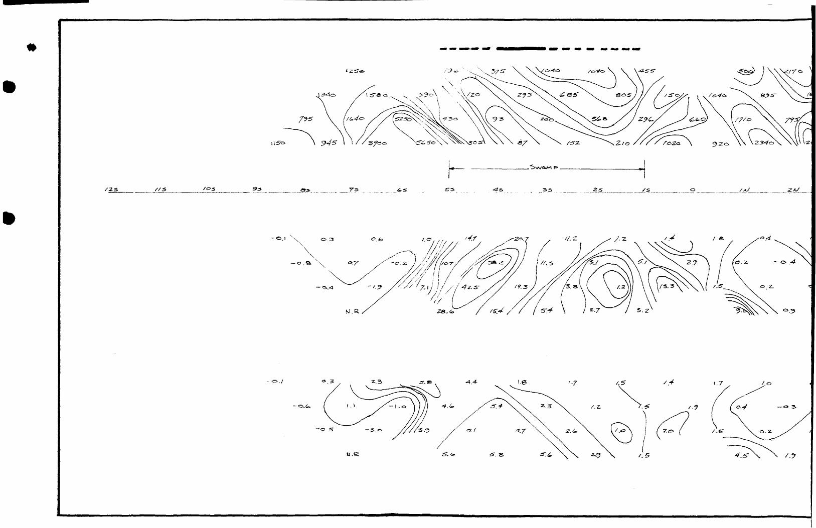
The attached composite plan gives an overall picture of results
obtained. Details ero shown on the data atrips for each 1s ...;; surveyed.

3
Kowhero aro there strong anomalous features. The composite
chowa all, even very client, I. P. effects), with the weaker features
plotted primarily for geological information. Overall results suggest
tha type of rcaponee that uii^ht be caused by two or several branching
r.hearu with gancr.-illy snail quantities of metallic nineralization
throughout.
There ere two crcas of relatively otronger response; anomaly
A is on lines 12 and 18 E, at 500 and 400 S respectively; anomaly B
is in and north of the email 1-kc on iir.as 6 E, O, 6 au d 12 W, at 100
to 300 15.
Copper ndrieralization io Unovm to exist in the vicinity o f each
of these enoxnlicc, being exposed on the trail between Chapu.cai and Flicker
lakes south of the baee line, sad on the shore of the tutall lake juat north
01 tha base line. Hov?evcr, einco the Una fjrid wfla cut aud the ourvoy
done in winter in heavy snov;, those chowings v?ore completely buried and
their exact location \*ith respect to the line grid io unknown. The precise
locations are critical in assessing results of the survey.
Since resulto fall in the "crey area" - r:ov;here stron; , but in two
locations having sufficient intensity to warrant closer investigation - it
is recoiuu:onded that sorao further surface prospecting, tvcnching aud saapling
bc dono before deciding whether drilling io warranted.
It is recommended initially that the various known showings bo
relocated with respect to the lino grid, end that they bc coraplctcly opened
up snd sampled, end results compered with I. P. response. Anomaly A can

probably be well exposed by trenching. Anomaly B probably cannot be
trenched cince It lies within end just off the end of o lake. However,
the tv,'o ^.norualies are of sinilar intensity, though B is irorc extencive,
nad cii v,Ii^; one will wake it possible to arrive ct a reasonable evaluation
of the other. At this point a decision e..u bc uadc ao to whether drilling
ii. warranted.
Kecpectful3y fcuhsii
I,. C. rhclr.n, M.A,Se. Cor. r.u 11J n g G c- o lo f i r. t.
rorito, Ovitario.
I-i:y, 1971.

ON THE THEORY OF INDUCED POLARIZATION
AND THE METHOD OF FIELD OPERATION
The following is in large part taken from the manuals of McPhar Geophysics
Limited, originators of the technique, and manufacturers of the equipment.
C
O
THEORY;
Induced Polarization as a geophysical measurement refers
to the blocking action or polarization of metallic or electronic conductors
in a medium of ionic solution conduction.
This electro-chemical phenomenon occurs wherever electrical
current is passed through an area which contains metallic t.inerals such
as base metal sulphides. Normally, when current is passed through the
ground, as in resistivity measurements, all of the conduction cakes place
through ions present in the water content of the rock, or soil, i.e. by
ionic conduction. This is because almost all minerals have a c.uch higher
specific resistivity than ground water. The group of minerals commonly
described as "metallic", however, have specific resistivities much lower
than ground waters. The induced polarization effect takes place at those
interfaces where the mode of conduction changes from ionic in the solutions
filling the interstices of the rock to electronic in the metallic minerals
present in the rock.
The blocking action or induced polarization mentioned above,
which depends upon the chemical energies necessary to allow the ions to
give up or receive electrons from the metallic surface, increases with the
time that a d.c, current is allowed to flow through the rock,.i.e. as
ions pile up against the metallic interface the resistance to current

O
ci
o
- 2 -
flow increases. Eventually, there is enough polarization in the form of
excess ions at the interfaces to effectively stop all current flow through
the metallic particle. This polarization takes place at each of the infinite
number of solution-metal interfaces in the mineralized rock.
When the d.c. voltage used to create this d.c. current flow is
cut off, the Coulomb forces between the charged ions forming the polarization
cause them to return to their normal position. This movement of charge creates
a small current flow which can be measured on the surface of the ground as a
decaying potential difference. This is the principle on which are based "Time
Domain" I.P. Surveys.
From an alternate viewpoint it can be seen that if the direction
of the current through the system is reversed repeatedly before the
polarization occurs, the effective resistivity of the system as a whole
will change as the frequency of the switching is changed. This is a con
sequence of the fact that the amount of current flowing through each
metallic interface depends upon the length of time that current has been
passing through it in one direction. This phenomenon is the basis for
"Frequency Domain" I.P. Surveys and the Kc?har system.
Since the I.P. effect is caused by electronic, i.e. metallic,
conductivity only, induced polarization measurements are an indication of
the total amount of metallic constituents in the rock. Thus all of the
metallic minerals in the rock, such as pyrite, as well as the ore minerals
chalcopyrite, chalcocite, galena, etc. are responsible for the induced
polarization effect. Some oxides such as magnetite, pyrolusite, chromite,
and some forms of hematite also conduct by electrons and are metallic.
All of the metallic minerals in the rock will contribute to the induced
polarization effect measured on the surface.

- 3 -
O
FIELD PROCEDURE;
Current is applied to the ground at two points a distance
(X) apart. The potentials are measured at two other points (X) feet
apart, in line with the current electrodes. The distance between the
nearest current and potential electrodes is an integer number (N) times
the basic distance (X).
The measurements are made along a surveyed line, with a
constant distance (NX) between the nearest/ current and potential
electrodes. In most surveys, several traverses are made with various
values of (N): i.e. (N) - l, 2, 3, 4, etc. The kind of survey required
decides the number of values of (N) used.
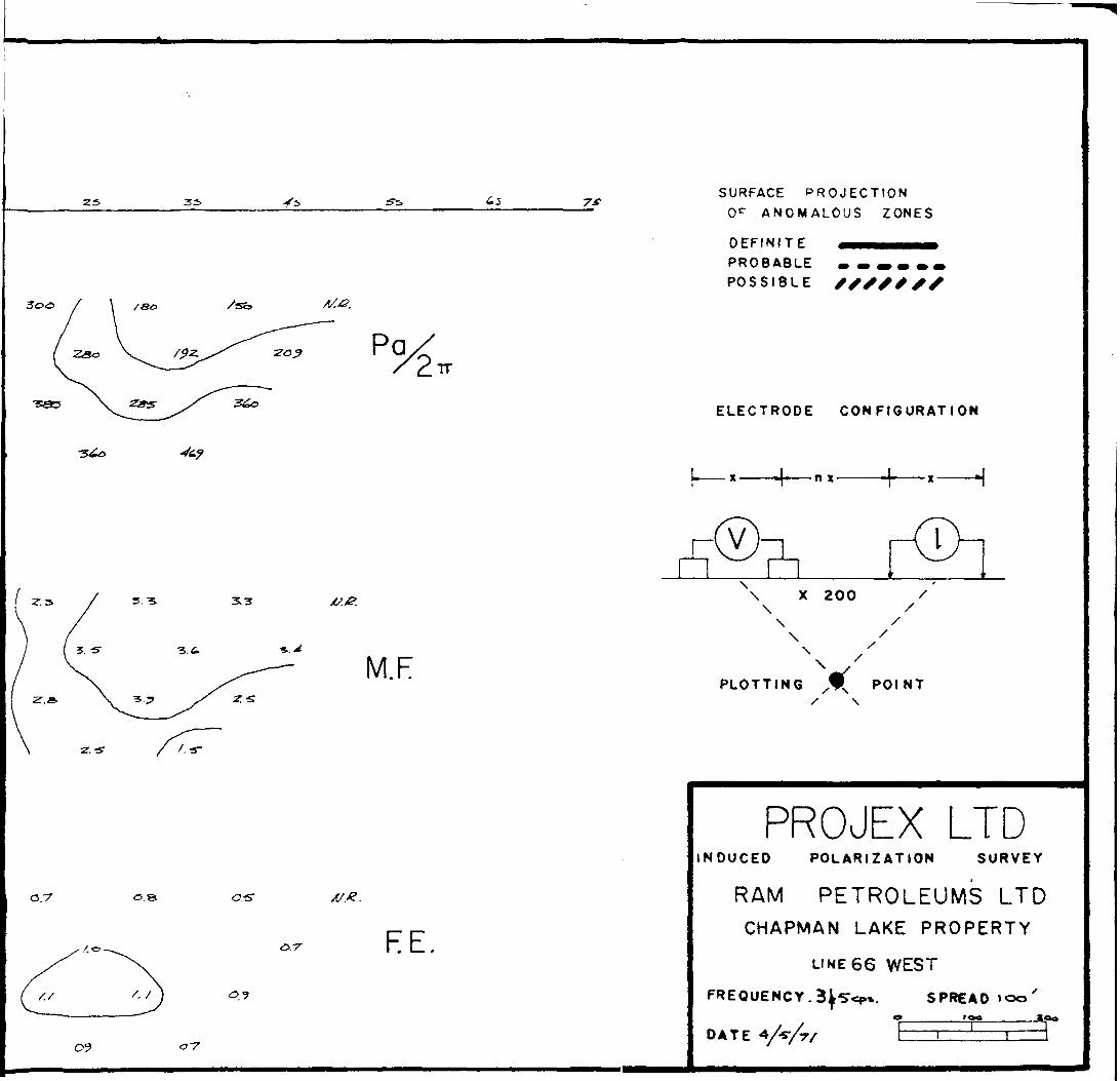
Three sets of data are recorded. The Apparent Resistivity
(P^/zTr") is, as the name implies, a measurement of the resistivity of
the rock,' and normally taken at a frequency of 5 c,p.s. The Frequency
Effect (F.E.) is a measurement, expressed as a percentage, of the change
in resistivity with frequency change, usually to 0.3 c-;p.s. The thirdj
Apparent Metal Factor (M.F.) is a calculated figure - Resistivity Frequency Effect x 1000
which by experience has been found best to combine the two measurements
and to illustrate the induced polarization effect.
The metal factor increases much more rapidly with metal content
of the rock than either frequency effect increases or resistivity decreases.
PLOTTING PROCEDURE;
In plotting the results, the three sets of values measured for
each set of electrode positions are plotted at the intersection of grid lines,
one from the center point of the current electrodes and the other from the
center point of the potential electrodes. The lateral displacement of a
given value is determined by the location along the survey line of the

- 4 -
O center point between the current and potential electrodes. The distance
of the value from the line is determined by the distance (NX) between the
current and potential electrodes when the measurement was made.
It should be emphasized that the resulting plot is merely a
convenient method of presentation of results and not a vertical section
along the survey line. The following sketches illustrates a typical
electrode configuration and plotting procedure.
-nx
-T^
S.otion, on line
n-l
7 . 8
x - E lectrode eprcocJ n: E lectrode seporofiorr
j
TYPICAL
ELECTRODE
CONFIGURATION
'l,2-3,4 2,3-4,5 3,4-5,6 4,5-6,7 5,6-7,8 6,7-8?__^MF MF ' M F MF. MF
1,2-4^.2,3-5,6 3,4-6,7 4,5'V;8 5,6-3,9___YMR-S/' M K MF. r.: F.
2-5,6^ 2,3-6,7 3,4-7,8 4,5*0,9
1,2-5,7 2,3-7,6 3.4-C.9
PLOTTING
PROCEDURE
J
Vc.luk.-t for obove configurotion (I*2G5"6) plotted ot this locotion .
o
2". 3-5. 3.3
-z. -s /.•f
Pa
0.7
/.o
TT
M. F
/t/.-e.
FE
SURFACE PROJECTION O c ANOMALOUS ZONES
PROBABLE ••••• POSSIBLE
ELECTRODE CONFIGURATION
-n x-
\\ X 200 \ \\
/
\ /
\PLOTTING X N̂ POINT
PROJEX LTDINDUCED POLARIZATION SURVEY
RAM PETROLEUMS LTDCHAPMAN LAKE PROPERTY
LI NE 66 WEST
FREQUENCY. 3^-5^*. SPREADo 'oo
DATE


//x//
7s. S*.
/oo
X S3
o.-
v./z
M.F
RE
SURFACE P ROJECTION O 17 ANOMALOUS Z ONES
PROBABLE . .... POSSIBLE
ELECTRODE CONFIGURATION
®-\\ X 200\ \ \
/
\ /\
PLOTTING xwx POINTx \
PROJEX LTDINDUCED POLARIZATION SURVEY
RAM PETROLEUMS LTD
CHAPMAN LAKE PROPERTY
LINE 6 0 WEST
FREQUENCY .385^* S PREAD ICO*
DATE 4/4/71

oxV?o
O'O
'
o
V) O'
\J. o
V) o

00 ^ X 3.000
PaTT
o./
/.G
M.F
2.
'.7
RE.
/.o
SURFACE PROJECTION
0^ ANOMALOUS ZONES
PROBABLE
POSSIBLE
ELECTRODE CONFIGURATION
-n x.
\ x 200\ s\\\ /\
PLOTTING XVN POINT x \
PROJEX LTDINDUCED POLARIZATION SURVEY
RAM PETROLEUMS LTD
CHAPMAN LAKE PROPERTY
LINE 54 WEST
FREQUENCY -3 B 9 *?*- S PREAD 'O '00'
DATE 4/3/TI

f
O N
O
O
.\ \
Q (A
O if

?
/e
x/e.
0.6*
0.7
M.F
SURFACE PROJECTION
OF ANOMALOUS Z ONES
PROBABLE m m^mm POSSIBLE
ELECTRODE CONFIGURATION
h
~L
\ K 200\\ x\
\ //\
PLOTTING x x̂ POINTs \
/.•z.
FE.
PROJEX LTDINDUCED POLARIZATION SURVEY
RAM PETROLEUMS LTD
CHAPMAN LAKE PROPERTY
LINE 48 WEST
FREQUENCY.3 a * CP*- S PREAD IOO'
DATE 3/2/71

*--
f*? O*fra
/x/ //////X/

-ZS .35
Z/c-o
o. -s o. z 0.2
O.'S 0.3 o.*
e.s.
0.7
/.o
Pa
0.7-
M.F
RE.
/OS
SURFACE PROJECTION
O r ANOMALOUS ZONES
PROBABLE
POSSIBLE
ELECTRODE CONFIGURATION
-n x
j
\ 200 /\\ x\ x\ /\ /
PLOTTING /WN POINT x x
PROJEX LTDINDUCED POLARIZATION SURVEY
RAM PETROLEUMS LTD
CHAPMAN LAKE PROPERTY
LINE 42 W EST
FREQUENCY 385 SPREAD l O O'O ^ * f**_______
DATE 4 |l|?l li ' l

(klN
O V
ft
. K.0 f*
O oO U .0
K
o
.0 aa
Nl
(A (A
\ \ \ \

XXX X XXXX/———— ////X
//c.
//o Pa.TT
82.
SURFACE PROJECTION
Or ANOMALOUS ZONES
PROBABLE * POSSIBLE
ELECTRODE CONFIGURATION
//Z
M. F
-n x-
\ X ZOO\ \
/.z
PLOTTING POINT x \
/.o OS.
07*
F E.
OS"
PROJEX LTDINDUCED POLARIZATION SURVEY
RAM PETROLEUMS LTDCHAPMAN LAKE PROPERTY
LINE 3 6 WEST
FREQUENCY .385^ S PREADl . *____________*^* x
DATE 3 /31/71 ' '

\
N
rt 6N
ON O"N O
1
N
\Jo1
v)DCi
OCD O
x
sx;
N
x1

xxxxxx xxxxx
7***
/S7
SURFACE PROJECTION
0^ ANOMALOUS ZONES
PROBABLE m m~mmm POSSIBLE //XXXXX
ELECTRODE CONFIGURATION
•3.-Z.
0.9
M.F
/.r
/3
RE
\ X 20O \\ \\ /\ /
PLOTTING X N̂ POINT x \
PROJEX LTDINDUCED POLARIZATION SURVEY
RAM PETROLEUMS LTDCHAPMAN LAKE PROPERTY
LINE 30 WEST
FREQUENCY.385^* SPREAD tOOe______/go*_____
DATE3/3O/7I li 1 !

XXX XXX
&.-S o.-sr
0.7
/.Z. 0.5-
/.z •2,S

SURFACE PROJECTION OF ANOMALOUS ZONES
PROBABLE POSSIBLE
ELECTRODE CONFIGURATION
0. 3 C5JZ-
o.7 C7-S" o.z- os f?.-3
Q -S
MF.
\ X 20O \ \ \
/
\ /\
PLOTTING POINT\
/.-f
/.r
-•S"
FE.
PROJEX LTDINDUCED POLARIZATION SURVEY
RAM PETROLEUMS LTD
CHAPMAN LAKE PROPERTY
LINE 24 WEST
FREQUENCY.3 ftS^ SPREAD |00'* '** x ^ **
DATE 3/25/71

\
\S
X'
Mx6
Irt
xcM O
tn MN rtM
O'CO'
V

-33 SURFACE D C?OJECT'ON
O- ANOMALOUS ZONES
PROBABLE •••••* POSSIBLE XXXXXXX
ELECTRODE CONFIGURATION
•n x
0.2 0.3 O.ST o -z.
c.-z. 0.4 o./
o.s 0.7 0-5
o. 3 0.6*
o.?
. Z
0.6,
/.z
Z. o
/••S
\ x 200\ \ \
\\ /
PLOTTING POINT
EE
PROJEX LTDNOUCED POLARIZATION SURVEY
RAM PETROLEUMS LTD CHAPMAN LAKE PROPERTY
LINE 1 8 WEST
FREQUENCY.3 8 5^*
DATE 3/2/71
SPREAD tOO'/O*' ve

-0'/
'*zsrY 3"i
1 JS--0
7 O/" .S-
\
7 C1'O
O O
/'C'
•z.'oii oeoD
-t: z/TO/

T-s,
Pa
/os
SURFACE 0ROJECT!ON O r ANOMALOUS ZONES
DEFINITE
PROBABLE POSSIBLE
ELECTRODE CONFIGURATION
n x
o./
o./
o/ o./
a. f
o./ M.F
J_______L
\ X 200\ \ \
//
\ /\ /
PLOTTING XWX POINT
/.G
FE
PROJEX LTDNDUCED POLARIZATION SURVEY
RAM PETROLEUMS LTD CHAPMAN LAKE PROPERTY
LINE 12 WEST
FREQUENCY.3 8
DATE .3 23 7 1
SPREAD 100O________too'

\ ss s
x1
w dv
—^
V
x,o
W C'
ViO'o\fsK O'
V* o
o M
xexo
x.6xd'
v O'O
IftO1
x.V
l

.23 S S
//Oo
a-3 Q Z
a o
O.Z.
/OS
SURFACE oq O c ANOMALOUS ZONES
PROBABLE POSSIBLE
ELECTRODE CONFIGURATION
x———-4-——n x
®\ x 200\ \ \
\
/
/\ /
PLOTTING XWS POINT x \
FE.
PROJEX LTDINDUCED POLARIZATION SURVEY
RAM PETROLEUMS LTD CHAPMAN LAKE PROPERTY
LI N E 69 wfST"
FREQUENCY. 3*'Se/* SPREAD /oo'
DATE 3/zt /rf l I

l l l l l
O O'Ndi
t)

o. z 0.3
o. z.
oz o o 3
0.7
Pa
M. F
SURFACE PROJECTION 0^ ANOMALOUS ZONES
PROBABLE POSSIBLE
ELECTRODE CONFIGURATION
•n x.
\ X 200\ /\ /
/
\ /\ /\
PLOTTING POINT
/.Z.
l--Z.
2.7
FE
PROJEX LTDINDUCED POLARIZATION SURVEY
RAM PETROLEUMS LTD CHAPMAN LAKE PROPERTY
L! NE O
FREQUENCY 3/^p*. SPREAD l O O'O________fog_______ea*
DATE 3/x/r/ j l ' l l

p N
\ '•K
M k s^ i* i ut lA M i/ ^
s,

/O /(J ///a
SURFACE PROJECTION O c ANOMALOUS ZONES
PROBABLE m m~mm POSSIBLE
ELECTRODE CONFIGURATION
O Ci
0.7" .s
o. x
M. F
-n t -
\ X ZOO '\ /\ s ,\s
PLOTTING ^ P OINTs \
l.-z
(.7 '.o
FE.
PROJEX LTDINDUCED POLARIZATION SURVEY
RAM PETROLEUMS LTDCHAPMAN LAKE PROPERTY
LINE 6 EAST
FREQUENCY.3 S 5^ SPREAD IOO'
DATE I2|l5[7l

xxxxx — ---,
ffs
S/O
0.7
/.-z
l l •2.. e. /".S
/.f /y

16 A/1 /ox/
P O.
SURFACE D ROJECT!ON O c ANOMALOUS Z ONES
PROBABLE POSSIBLE
ELECTRODE CONFIGURATION
2.1
7 C*
\ X 200 /
\ x\
\ /\
PLOTTING POINT
e?. Z
X. 3
F E.
PROJEX LTDNDUCED POLARIZATION SURVEY
RAM PETROLEUMS LTD CHAPMAN LAKE PROPERTY
LINE 1 2 EAST
FREQUENCY.3 Q 5cP*. SPREAD
DATE 1 2/19/70 l i *-

/•o
•z. "o/v
09?

-Z x/
Pa
//A/ /.Z*/
SURFACE PROJECTiON O c ANOMALOUS Z ONES
PROBABLE POSSIBLE
ELECTRODE CONFIGURATION
M.F
•n x
\
~\
\ X 20O\ x\ \
\ /\
PLOTTING x x̂ POINTs \
o S
— o 2,
F.E.PROJEX LTD
INDUCED POLARIZATION SURVEY
RAM PETROLEUMS LTD CHAPMAN LAKE PROPERTY
LINE ! 8 east
FREQUENCY-^ fScp*. S PREAD
DATE
'(rS''-n
S o-
I'O-
f'es://

x//
BZO
SURFACE PROJECTION O c ANOMALOUS ZONES
PROBABLE •••••* POSSIBLE SX/X'XX
ELECTRODE CONFIGURATION
l//.-S. 0.7 ,. ( 7
^
o,
M.F
n x-
\\ X 200\ \ \ \
/
\ /
PLOTTING ^ P OINT s \
2:6
2T? /we
3.'
/.r -CMT
F E.
PROJEX LTDINDUCED POLARIZATION SURVEY
RAM PETROLEUMS LTD'"* * *
CHAPMAN LAKE PROPERTY
LINE 24 EAST
FREQUENCY .3 a5y*. SPREAD I00'
DATE 3/20/71xoe' Zoo'

.N "l
N vi
*
X. A,
N N
S N
S
N
N
N
N
\
X

5-3 f o a
Pa
/.O
FE
SURFACE PROJECTION OP ANOMALOUS Z ONES
PROBABLE • POSSIBLE
ELECTRODE CONFIGURATION
•n x-
\\ X 200\\ /
\ :''PLOTTING M. P OINT
PROJEX LTDINDUCED POLARIZATION SURVEY
RAM PETROLEUMS LTD CHAPMAN LAKE PROPERTY
LINE 3 O EAST
FREQUENCY.3S 3*p*. S PREAD 1OO'O/oa' *
DATE 2 /20/71

2:0
o//-
52- S"/
xxxxxxxxxx/xxxx
•z: o

/osSURFACE DROJECT!ON
O c ANOMALOUS Z ONES
•S s G*
Pa.TT
PROBABLE . POSSIBLE
ELECTRODE CONFIGURATION
o.s-
MF
-n x-
\ X 200\ \\
\\'
PLOTTING ^ P OINT/ \
3.8
/.o
FE.
PROJEX LTDINDUCED POLARIZATION SURVEY
RAM PETROLEUMS LTD CHAPMAN LAKE PROPERTY
LINE 36 EAST
FREQUENCY.38 5^* SPREAD IOO'o___
DATE 2 |2I|7!

\
\S\\ \ \ \ \l tll lll lx1 sN
S
X
S
X
S
S
X
X
Sx xx x
\8
\
o\'
N x'
x
x'

z.* 0.3 o. z o.;T 0-9
o./
0.5- o.-z. 0.3
o.-z. 0.7
SURFACE PROJECTION
OF ANOMALOUS ZONES
PROBABLE ••www POSSIBLE S/X/X/X
M.F
f:E.
ELECTRODE CONFIGURATION
-n t -
Vrvvnx\ X 200\ \ \\ /
/\PLOTTING ^ P OINT
s \
PROJEX LTDINDUCED POLARIZATION SURVEY
RAM PETROLEUMS LTD CHAPMAN LAKE PROPERTY
LINE 42 EAST
FREQUENCY.3 8 5epc SPREAD l OO*
DATE

.x M
x.
x. is)
x N
.x
f
fsM O
vi N
l l l i i t l i i i i i

•fs. to*
Pa
M.F
RE•z.7
SURFACE PROJECTION OF ANOMALOUS ZONES
PROBABLE * m**mmm POSSIBLE //////X
ELECTRODE CONFIGURATION
-n i-
\ X 200\ \\
/
\ //\
PLOTTING ^̂ POINT / \
PROJEX LTDINDUCED POLARIZATION SURVEY
RAM PETROLEUMS LTDCHAPMAN LAKE PROPERTY
LINE 4 8 EAST
FREQUENCY 3 * 5*"* S PREAD
DATE ZJ23J7I

x '•K
.•s "ri .N
.N VAI
X, o .\
N K
N N
l \ \

SURFACE PROJECTION OF ANOMALOUS ZONES
PROBABLE . * o * * POSSIBLE
ELECTRODE CONFIGURATION
O.
OB 0.2 M. F
n x-
\\ X 200\ \ X\
/
\ //\
PLOTTING ^ P OINT/ \
/.r.
PROJEX LTDINDUCED POLARIZATION SURVEY
RAM PETROLEUMS LTDCHAPMAN LAKE PROPERTY
LINE 5 4 EAST
FREQUENCY.S 8k* c,*. SPREADI00'
DATE "

N
N
y y^
H o
MO'
w o
Vi O'
ffs
-t-

\
550
7
/.-S"
7S.
M.F
RE.
SURFACE PROJECTION O c ANOMALOUS Z ONES
PROBABLE POSSIBLE
ELECTRODE CONFIGURATION
•n x-
\\ X 200\ \\ \\ /
PLOTTING x v̂ POINT x \
PROJEX LTDINDUCED POLARIZATION SURVEY
RAM PETROLEUMS LTD CHAPMAN LAKE PROPERTY
LINE 60 EAST
FREQUENCY,3a5c"3 SPREAD 1OO'* 'Oa' To
DATE 2 /26/71

3
o *\in
x
x s
KQX'
VMx x"

Z-S 3-3 .s-i
TT
SURFACE PROJECTION
O r ANCMALOO'S ZONES
PROBABLE POSSIBLE
ELECTRODE CONFIGURATION
M.F
•n i.-
\ 200 /\ /\ \
\\ /
PLOTTING XWN POINTx \
.•6.
RE.
PROJEX LTDINDUCED POLARIZATION SURVEY
RAM PETROLEUMS LTD CHAPMAN LAKE PROPERTY
LINE 6 6 EAST
FREQUENCY.3 8 5^5 SPREAD I00'•^_____ t.
DATE 2 l27(7l f l ~-^ l J

z-s
Zrf^
/.s/
O O z. o
0.5- f /:A \~ ;̂
0.7
X.

XXXXX x xx x
TT
SURFACE PROJECTION O c ANOMALOUS ZONES
PROBABLE •••••^ POSSIBLE /XXX/XX
ELECTRODE CONFIGURATION
-n x
o. 3 o X
O. (i
/.o
o. z.
MF
\ x 200 \ \ / \
/
\ /\
PLOTTING X N̂ POINT x \
••-i
RE.
PROJEX LTDINDUCED POLARIZATION SURVEY
RAM PETROLEUMS LTDCHAPMAN LAKE PROPERTY
LINE T2 EAST
FREQUENCY -3 a5c3 SPREAD IOO f
DATE 3/2/71

/•y
OVy
S .2
ZJ?
c? /y/ />2^
xxxxxx

3:5
22*
7-3SURFACE PROJECTION
O c ANOMALOUS ZONES
PROBABLE POSSIBLE
ELECTRODE CONFIGURATION
-n j.-
3.9
MF.
z./ 5.
"Z. 5^
RE.2. 2
\ X 200 s\ S\ S\ '
\ '\ s'
PLOTTING /^[ POINT/ \
PROJEX LTDINDUCED POLARIZATION SURVEY
RAM PETROLEUMS LTDCHAPMAN LAKE PROPERTY
LINE 7 8 EAST
FREQUENCY .3 a 5^5 SPREAD lOO'o
DATE j: j:

\9
\\\
to
\\
\
\\
\
\
*
\
&V
JO'
MM
x!
*i
Mtox:V
(S K)
0\
O
10
x
KN
M*
V)xV
x.
ffi*o O

ASSESSMENT W(2.7*2 ROPE LAKE 900
l. Type of Survey Induced Polarisation'••••••••••••••••••••••••.••••••.••.•••••.••.•.••AMWI.BMMIVMMWWMBMWWMMaiM**
2. Township or Area ............"W.^J^.tJ*?^
3. Numbers of Mining Claims Traversed.by Survey
...................Ta.2WQw*Jk,;:^/-i fa. y*, 7-?, ^ - i ^J -r- s
TB 286640, 41, 4jL 43, 44, 45, 46, 47. 4 49 *^\ c ctKut( l- J- 3 ........................^..t.-.l.^.^!..^^.!.^'...^........-....................TB 266650, 51, 52, 53, 54, 55, 56, 4
288038 4 39 o H c o o' ' ^ f \ ^ KJ o C Kf -d
4. Number of Miles of Line Cut __...
*5. Number of Stations Established -..
*6. Make and type of Instrument Used .
*7. Scale Constant or Sensitivity .................
*8. Frequency Used and Power Output ...?*?.f.?.?P*.
Flown
9. Summary of Assessment Credits (details on reverse side)
Total 8 hour Technical Days (Include Consultants, Draughting etc.)
Total 8 hour Line-Cutting Days ...................
Calculation
304 x 7 - 2128 . 2128Technical Line-cutting
allowable
Number of claims
Assessment credits per claim
The dates listed on this form represent working time spent entirely within the limits of the above listed claims ll Check If otherwise, please
Dated : . . . . . ̂ 2,. .1971. Signed:
Note: (A) * Complete only if applicable.(B) Complete list of names, addresses and dates on reverse side(C) Submit separate breakdown for each type of survey.(D) Submit in duplicate.

ASSESSMENT WORK BREAKDOWN
1. FIELD WORK
Type of Work Name 6c Address Dates Worked6 - 10 Dec.70
Number of 8 hour days
" M.Dignam "
Helper W.. Cumerf qrjd
" G.Mlnthom"* r G'eraid" ComeViT " Dan Coneau
PDMOIIT TAMTc vaorgB uapar
M M IIn H H n ,, ,, ,,
18 Feb. - 4 Mar., " " " " 18 MAT* -.7 AP1.7J-...
H II M II II
.....52....
.....12....
Tarrace Bay* Ont. 6 Jan^4 Mar .4 18 Mar. -7 Api. 71H II H tl tt II II II II II II 1
ir 1r ir 18 Mar. - 7 Apl.71 M " " 18 Feb. - 4 Mar. 71
49 4?20 14
Name 6c Address Dates Worked (specify in field or office)Number of 6 hour days
3. DRAUGHTSMAN, TYPING, OTHERS (specify)
Name 6t Address Type of Work Dates WorkedNumber of 8 hour days
...K^-.^
4. LINE-CUTTING
Name Address
TOTAL 8 HOUR TECHNICAL DAYS
Dates WorkedNumber of 8 hour days
TOTAL 8 HOUR LINE-CUTTING DAYS

- -f
s
490 07'30'
\-
87 0 I5'
490OO —
42E03SWC039 2 .702 ROPE LAKE 200
AREA OF
ROPE LAKEDISTRICT OF
THUNDER BAY
THUNDER BAY MINING DIVISION
SCALE: 1-INCH-40 C HAINS
LEGEND
PATENTED LANDCROWN LAND SALELEASESLOCATED LANDLICENSE OF OCCUPATIONMINING RIGHTS ONLYSURFACE RIGHTS ONLYROADSIMPROVED ROADSKING'S HIGHWAYSRAILWAYSPOWER LINESMARSH OR MUSKEGMINESCANCELLED
C.&
Loc LO.
M R O.S HO
NOTES400 Surface Rights Reservation around ati lakes and rivers.
DATE OF is SUE
OHT. DEPT. OF MJNES
NATIONAL TOPOGRAPHIC SERIES 42 E 3
PLAN NO. MONTARIO
DEPARTMENT OF MINES AND NORTHERN AFFAIRS
ff. <
.\- -v
X *i
*'' t..
•V OJ

\ x
KE
Y
PLA
N
LEG
EN
D
BA
SE
a
PIC
KE
T
LIN
ES
S
UR
VE
YE
D
DE
FIN
ITE
PR
OB
AB
LE
PO
SS
IBLE
——
——
—I
SU
RFA
CE
P
RO
JEC
TIO
N
OF
AN
OM
ALO
US
ZO
NE
S
PR
OJE
X
LTD
CO
MP
OS
ITE
P
LAN
ND
UC
ED
P
OLA
RIZ
AT
ION
OF SU
RV
EY
RA
M
PE
TRO
LEU
MS
LT
DC
HA
PM
AN
LA
KE
P
RO
PE
RT
Y
25 A
PRIL
19
71
*2
.70
2
RO
PE
LAK
E210
t* jl -
- ^
-"'--*-
*
.