rainsoft air master ultra
TRANSCRIPT

8/7/2019 Rainsoft Air Master Ultra
http://slidepdf.com/reader/full/rainsoft-air-master-ultra 1/9
R a in so ft D iv is io n o f A q u io n W a te r T re atm e n t P ro d uc ts , lt
2 08 0 E ast L un t A ve nu e, E lk G ro ve V illa ge , Il lin ois 6 0 00
T el: 8 47 -4 37 -9 40 0 • www.ra insof t . com
Treatment Systems
A IR S T E R U L T R f t
Dll i l©~[}DO~~®ll i l~@W])®[{@ ~[}llil[]][}D
REV 11 / 2# U T

8/7/2019 Rainsoft Air Master Ultra
http://slidepdf.com/reader/full/rainsoft-air-master-ultra 2/9
TABLE OFCONTENTS
Enjoying Your Airmaster Ultra Unit 3
Important Safety Instructions 3
Unpacking Your Airmaster Ultra Unit 4
Airmaster Ultra Installation 5
Adjusting the Ozone Output Level 6
Maintenance Requirements 7
.Airmaster Ultra Parts List 8
Specifications 8
Troubleshooting Guide , 9
Warranty 1 0
Rectangle Installation Template 11
Hole Saw Installation Template 12
8/7/2019 Rainsoft Air Master Ultra
http://slidepdf.com/reader/full/rainsoft-air-master-ultra 3/9
Congratulationsl You now own the finest whole-house air treatment system available to homeowners.
To make operating and maintaining your unit as simple as possible, please read the contents of this
Owner's Manual.
This unit was shipped from the factory ready for operation and will begin delivering cleaner, fresher air
the instant your heating/cooling system is turned on.
This unit is designed to help remove household odors ranging from food, tobacco smoke, pets and other
objectionable smells that may be present in your home.
To receive optimal benefit and performance from the unit, your furnace or air conditioner fan should be
in the "ON" position at all times.
IMPORTANT SAFETY INSTRUCTIONS
Always make sure the system is unplugged during installation or service procedures.
WARN ING :
T h e u ltra vio le t lig ht p ro du ce d b y th e
U V lam ps is harm fu l to th e e ye s. Don ot lo ok d ire ctty a t th e lam p s. S ho uld
it b ec ome ne ce ss ar y to look at the
lamps, u s e UV -p ro te cte d sung la ss es .
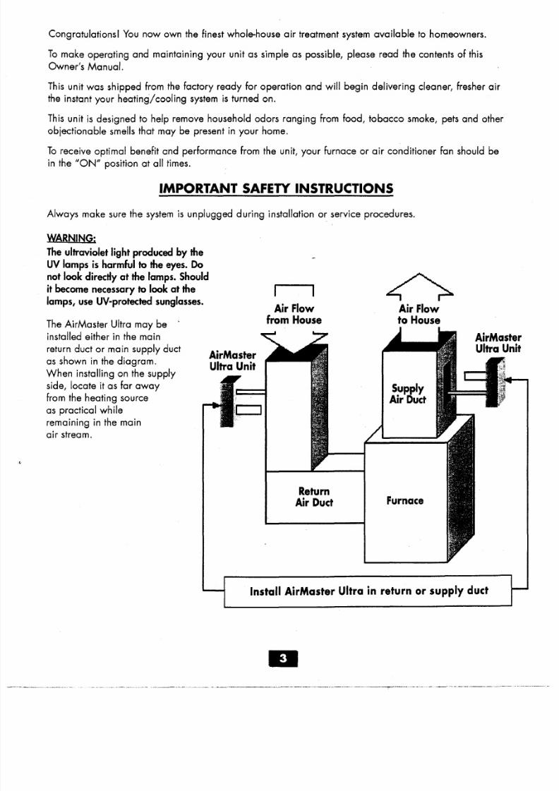
The AirMaster Ultra may be .
installed either in the main
return duct or main supply duct
as shown in the diagram.
When installing on the supply
side, locate it as far away
from the heating sourceas practical while
remaining in the main
air stream.
A ir F lowfrom H ou se
AirMasterU ltra Un it
ReturnA ir D uct
<>A ir F lo wto H ous e
Supply
A ir D uct
Furnace
Insta ll A irM aster U ltra in return or supp ly duct

8/7/2019 Rainsoft Air Master Ultra
http://slidepdf.com/reader/full/rainsoft-air-master-ultra 4/9
UNPACKING YOUR AIRMASTER ULTRA UNIT
Unpacking the Airmaster Ultra unit.
1. Each unit is shipped with the cover separated from the main
chassis assembly. This allows for the main chassis
assembly to be ready for installation.Germicidal
UV Lamp
2. Carefully remove unit from the package. The lamps arefragile and proper care must be taken when removing
packaging that is placed around them.Air FlowSensor--~
3. Do not touch the lamps with your bare hands, as oils from
your hands can create "hot spots" which reduce the lamp
life. In case of contact with the lamp, wipe the lamp clean
with a soft cloth dampened with rubbing alcohol.
4. Check the parts list below to make sure you have all of the components.
• One Airmaster Ultra air treatment system
- Main chassis assembly
- Cover- Two cover attachment screws
• One wall-mount transformer
• Four self-tapping screws
• Installation/owners manual
• Warranty card
• Wiring to connect from transformer to unit
(20', two-conductor cable with plug)
• 2 crimp terminals
• Wire tie
Main ChassisAssembly with Cover Removed
Display BoardRibbon Cable--'
Main Power Jack
Lamp Connector
Ozone Lamp End
- White Lamp Base
White Wires
Power Cord Retaining Wire Tie _..,
Cover
Display Board(under cover)
."» a
0Q,
~ :E;; a ~ Cl
!! l<II
."~ z3 0'
• l~
rn» c:
!£ :EIU'l ~Q,
;~
! ! ! . .! ! ! . .
. '--t
N'
r'-'1 ~ S § .
m
!!l~,e'
r i l_ \ ~
5 . .iH~~
Side View
Ballast
Air Flow Sensor
Germicidal Lamp En
- Yellow Lamp Base
Yellow Wires

8/7/2019 Rainsoft Air Master Ultra
http://slidepdf.com/reader/full/rainsoft-air-master-ultra 5/9
AIRMASTER ULTRA INSTALLATION
W h ile p re fo rm in g in sta lla tio n p ro ce du re s a ll p ow er to the un it m ust be 'O ff' and there must be no airflow
th ro ug h th e h eatin g/co olin g sy ste m.
1. One of two templates may be used for installation of the AirMaster Ultra.
• 'Rectangle Installation Tempiate'located on page 11.
• 'Hole Saw Installation' located on page 12.
2. Center the installation template on the ductwork using tape. N ote: T he insta lla tion tem plate an d un it m ust
be m ounted lengthw ise and in d irec tion o f 'A irAow ' so tha t the UV G erm ic ida l Lam p is upstream and the
UV O zone Lam p is dow nstream .
3. Rec ta ngle I ns ta lla tio n T emp la te : Trace the cut out hole pattern on to the ductwork and mark holes for the
four mounting screws. H ole S aw In sta lla tio n T em plate : Mark holes for the four mounting screws.
4. Cut out openings in ductwork for the unit. See template for step and recommended tools.
5. Position AirMaster Ultra 'Main Chassis Assembly' into ductwork and secure with the self tapping screws
provided, using a 5/16" nut driver.
6. Cut the two conductor power cord to length, strip ends back 3/8" and crimp on the two fork connectors
provided.
7. Slide fork connectors under transformer screw-heads and tighten.
8. Insert the power cord through the cord retaining wire tie (located next to the ozone lamp). Plug power
cord into the main power jack.
9. Allow for a service loop in the power cord between the wire tie and the main power jack. Then draw the
wire tie tight around the power cord. No te : Cu t o ff any excess of the w ire tie w ith side cu tte rs . D o no t cu t
the pow er cord .
10. Plug the display board ribbon cable into the display board, located under cover and secure cover to mai
chassis. Assemble using the two screws provided.
11. Plug the transformer into a non-switched 120 VAC outlet. Note : All lights w ill rem ain on fo r 30 to 120
seconds . A fter th is tim e the' A irflow ' and 'O dor N eutra lize r' ligh ts w ill tu rn o ff.
12. Turn 'On' heating/cooling system and allow it to operate for five minutes, at this time all lights should
illuminate.
13. Turn 'Off' heating/cooling system, the AirMaster Ultra will shut down within 5 to 30 seconds. After this
time the 'Airflow' and 'Odor Neutralizer' lights will turn off. The 'Power' and 'Germicidal' lights willremain on when unit is not in operation.
14. The AirMaster Ultra is now ready for use.
N ote : O zone air treatm ent occurs on ly w hen air is c ircu la ting thro ugh the heatin g/coo ling system. For
m axim um e ffe ctive nes s a nd co ntin uo us a ir p urific atio n, tu rn th e th erm os ta tic co ntro ller sw itch fro m th e
A U TO p os itio n to the O N pos ition . The sw itch is located on the therm ostat. O pen w indows or doors and d irty
d uc tw ork m a y d im in is h th e u nit's e ffe ctiv en es s.

8/7/2019 Rainsoft Air Master Ultra
http://slidepdf.com/reader/full/rainsoft-air-master-ultra 6/9
ADJUSTING THE OZONE OUTPUT LEVEL
T he slid e sw itch o n th e co ver is u sed to ad ju st th e o zo ne ou tp ut leve l. T he settin gs a re lo w, m ed an d h ig h.
LOW - Use in an average-sized home with no pets, no tobacco smoke odors and minimum household odors.
M E D I U M - Use in an average-sized home with pets, confined tobacco smoke odors and minimum household
odors.
H IGH - Use in an average-sized home with pets, heavy tobacco smoke odors throughout the home and
moderate household odors.

8/7/2019 Rainsoft Air Master Ultra
http://slidepdf.com/reader/full/rainsoft-air-master-ultra 7/9
MAINTENANCE REQUIREMENTS
The lamp cleaning schedule is determined by air quality. The recommended cleaning interval is every
12 months. The lamp replacement schedule is based on running time. The recommended replacement
interval is 24 months. Note: Do not touch the lamps with bare hands. Oils from the hands can create
"hot spots" which reduce the lamp life. Handle by either the end caps or use a soft cloth. In case of
contact with the lamp, wipe the lamp clean with a soft cloth dampened with rubbing alcohol.
C LEA NIN G THE LAM PS: Recommended every 12 months
1. Unplug the transformer from the wall outlet.
2. Remove the two screws from the cover of the unit and remove the cover.
3. Remove the four sheet metal mounting screws from air duct.
4. Carefully remove the unit from the air duct.
5. Using a soft cloth dampened with rubbing alcohol, wipe down the unit and the lamps. If there is
a large buildup of dust particles, you may wish to use a can of compressed air first to remove the
majority of the dirt.
6. Carefully replace unit into air duct.
7. Replace sheet metal screws, the cover, the two screws and plug the transformer into the wall outlet.
REP LACIN G THE LAMP S: Recommended every 24 months
NOTE: Use only RainSoft-approved lamps for replacement. Standard off-the-shelf lamps are not
compatible with your RainSoft AirMaster Ultra unit.
1. Unplug the transformer from the wall outlet.
2. Remove the two screws from the cover of the unit and remove the cover.
3. Disconnect the lamp connector from the end of a lamp.
4. loosen the lamp lock nut from around the end of the lamp by turning it counterclockwise and
remove (pliers may be required).
5. Remove the metal washer.
6. Remove lamp by grasping the rubber bushing around the end of the lamp. With a gentle rocking
motion, loosen the bushing from its seat and carefully slide it straight out.
7. Remove the rubber bushing from the old lamp and install it on the new lamp.
8. Slide the new lamp back into the lamp opening. Handle lamp by the end cap(s).
9. Re-install the metal washer and lamp lock nut. Carefully tighten the lamp lock nut.
10. Reconnect the lamp connector to the end of the lamp.
11. Repeat steps #3 to # 10 when replacing the other lamp.
12. Replace the cover and secure it with the two screws.
13. Plug the transformer into the wall outlet.

8/7/2019 Rainsoft Air Master Ultra
http://slidepdf.com/reader/full/rainsoft-air-master-ultra 8/9
A IRMASTER ULTR A P AR TS L IS T
ITEM# DESCRIPTION
4
5
6
7
PART # SPECIFICATIONS
2
3
AirMaster Ultra Assembly 65052
AirMaster Ultra Ozone Lamp 6550 1
AirMaster Ultra Germicidal
Lamp 65048
AirMaster Ultra Fuse 65005
AirMaster Ultra Flow Sensor 65061
Germicidal Lamp
Germicidal lamp is 254 nm, hot filament.
Average life is 20,000 hours.
Ozone Lamp
Ozone lamp is 185 nm, cold cathode.
Average life is 20,000 hours.
AirMaster Ultra Ballast (Board) 65062
AirMaster Ultra Transformer 65000
Input
24 Yac, 60 Hz, 50YA
8 AirMaster Ultra Display (Board) 65063
9 AirMaster Ultra Ribbon Cable 65064
C D
._ - ----.._
- -- -
Ell

8/7/2019 Rainsoft Air Master Ultra
http://slidepdf.com/reader/full/rainsoft-air-master-ultra 9/9
TROUBLESHOOTING GUIDE
SYMPTOM SOLUTION
N o pow er Verify that the transformer is properly plugged into wall
outlet and the power cord into the power jack on unit.
If the cord is properly connected, test the wall outlet with
AC tester to make certain it is functioning properly. If not
working, consult an electrician.
If u nit s till d oe s n ot fu nc tio n If there is power to the wall outlet, remove cover from the
Airmaster Ultra unit, unplug the power cord from the power
jack on the AirMaster unit. Using a voltmeter, measure the
AC voltage from the transformer. Make sure the voltage is
21 to 26 volts. li not, replace the transformer. (Item # 7,
Page 8).
If unit is still not working, remove cover from the AirMaster
unit and check the fuse on the circuit board. If fuse is
blown, replace (Item # 4, Page 8).
Check the power light. If light is still not on, replace the
ballast. (Item # 6, Page 8).
Fo r the fo llow ing tes ts m ake su re there is no a ir flow
a c ro s s u n it .
A ir f low tes t
Unplug the power cord from the power jack for 1 to 2
minutes. Plug the power cord back into the power jack. The
'Air Flow' light will illuminate for 30 to 120 seconds. After
the light turns off, start the heating/cooling system. The
'Air Flow' light should illuminate within 30 seconds. If not,
replace the air flow sensor (Item # 5, Page 8). If that does
not work, replace the ballast. (Item # 6, Page 8).
T es tin g th e la m ps T es tin g th e lam ps requ ire s th e h ea tin g/co olin g s ys tem to b e
runn ing .
If ozone lamp is not lit, replace (Item # 2, Page 8).
If the germicidal lamp is not lit, replace (Item # 3, Page 8).
If this does not work, replace the ballast (Item # 6, Page 8).
If above tes ting does no t w ork , con tac t you r loca l R ainS oft D ea le r.