railway applications electronic equipment used on rolling ... · part 3-2: rolling stock apparatus...
TRANSCRIPT

BRITISH STANDARD BS EN 50155:2007
Railway applications — Electronic equipment used on rolling stock
The European Standard EN 50155:2007 has the status of a British Standard
ICS 45.060.10

BS EN 50155:2007
This British Standard was published under the authority of the Standards Policy and Strategy Committee on 31 August 2007
© BSI 2007
ISBN 978 0 580 57012 4
National foreword
This British Standard is the UK implementation of EN 50155:2007. It supersedes BS EN 50155:2001 which is withdrawn.The UK participation in its preparation was entrusted to Technical Committee GEL/9, Railway electrotechnical applications.A list of organizations represented on this committee can be obtained on request to its secretary.This publication does not purport to include all the necessary provisions of a contract. Users are responsible for its correct application.Compliance with a British Standard cannot confer immunity from legal obligations.
Amendments issued since publication
Amd. No. Date Comments

EUROPEAN STANDARD EN 50155 NORME EUROPÉENNE
EUROPÄISCHE NORM July 2007
CENELEC European Committee for Electrotechnical Standardization
Comité Européen de Normalisation Electrotechnique Europäisches Komitee für Elektrotechnische Normung
Central Secretariat: rue de Stassart 35, B - 1050 Brussels
© 2007 CENELEC - All rights of exploitation in any form and by any means reserved worldwide for CENELEC members.
Ref. No. EN 50155:2007 E
English version
Railway applications - Electronic equipment used on rolling stock
Applications ferroviaires - Equipements électroniques utilisés sur le matériel roulant
Bahnanwendungen - Elektronische Einrichtungen auf Schienenfahrzeugen
This European Standard was approved by CENELEC on 2007-03-01. CENELEC members are bound to comply with the CEN/CENELEC Internal Regulations which stipulate the conditions for giving this European Standard the status of a national standard without any alteration. Up-to-date lists and bibliographical references concerning such national standards may be obtained on application to the Central Secretariat or to any CENELEC member. This European Standard exists in three official versions (English, French, German). A version in any other language made by translation under the responsibility of a CENELEC member into its own language and notified to the Central Secretariat has the same status as the official versions. CENELEC members are the national electrotechnical committees of Austria, Belgium, Bulgaria, Cyprus, the Czech Republic, Denmark, Estonia, Finland, France, Germany, Greece, Hungary, Iceland, Ireland, Italy, Latvia, Lithuania, Luxembourg, Malta, the Netherlands, Norway, Poland, Portugal, Romania, Slovakia, Slovenia, Spain, Sweden, Switzerland and the United Kingdom.
ICS 45.060.10 Supersedes EN 50155:2001 + A1:2002
EN 50155:2007 - 2 -
Foreword This European Standard was prepared by the Technical Committee CENELEC TC 9X, Electrical and electronic applications for railways. The text of the draft was submitted to the Unique Acceptance Procedure and was approved by CENELEC as EN 50155 on 2007-03-01. This European Standard supersedes EN 50155:2001 + A1:2002. This EN 50155:2007 has been aligned with the new EN 50121 series and addresses some Portuguese comments. The following dates were fixed: – latest date by which the EN has to be implemented
at national level by publication of an identical national standard or by endorsement
(dop)
2008-03-01
– latest date by which the national standards conflicting with the EN have to be withdrawn
(dow)
2010-03-01
This European Standard has been prepared under a mandate given to CENELEC by the European Commission and the European Free Trade Association and covers essential requirements of EC Directives 96/48/EC and 2001/16/EC. See Annex ZZ.
____________

- 3 - EN 50155:2007
Contents
1 Scope ...........................................................................................................................................5 2 Normative references ..................................................................................................................5 3 Definitions....................................................................................................................................7 4 Environmental service conditions of operation.........................................................................8 4.1 Normal service conditions ..............................................................................................................8 4.2 Special service conditions............................................................................................................10 5 Electrical service conditions.....................................................................................................10 5.1 Power supply ...............................................................................................................................10 5.2 Supply .........................................................................................................................................12 5.3 Installation ...................................................................................................................................12 5.4 Surges electrostatic discharge and transient burst susceptibility tests ..........................................12 5.5 Electromagnetic compatibility .......................................................................................................12 6 Reliability, maintainability and expected useful life ................................................................12 6.1 Equipment reliability .....................................................................................................................12 6.2 Useful life.....................................................................................................................................13 6.3 Maintainability ..............................................................................................................................13 6.4 Maintenance levels ......................................................................................................................13 6.5 Built-in diagnostics .......................................................................................................................14 6.6 Automatic test equipment ............................................................................................................14 6.7 Alternative methods for fault diagnosis.........................................................................................14 6.8 Purpose built test equipment and special tools.............................................................................14 7 Design ........................................................................................................................................15 7.1 General........................................................................................................................................15 7.2 Detailed practices - Hardware ......................................................................................................15 7.3 Detailed practices - Software .......................................................................................................17 7.4 Equipment features......................................................................................................................19 8 Components...............................................................................................................................20 8.1 Procurement ................................................................................................................................20 8.2 Application...................................................................................................................................21 9 Construction ..............................................................................................................................21 9.1 Equipment construction ...............................................................................................................21 9.2 Component mounting...................................................................................................................21 9.3 Electrical connections ..................................................................................................................22 9.4 Internal flexible wiring (electrical and optical) ................................................................................23 9.5 Flexible printed and strip wiring ....................................................................................................23 9.6 Printed board-flexible and rigid .....................................................................................................24 9.7 Protective coatings for printed board assemblies .........................................................................24 9.8 Identification ................................................................................................................................25 9.9 Mounting......................................................................................................................................25 9.10 Cooling and ventilation.................................................................................................................25 9.11 Materials and finishes ..................................................................................................................26

EN 50155:2007 - 4 -
10 Safety .........................................................................................................................................26 10.1 General........................................................................................................................................26 10.2 Functional safety..........................................................................................................................26 10.3 Personnel safety..........................................................................................................................26 11 Documentation ..........................................................................................................................26 11.1 Supply and storage of documentation ..........................................................................................26 11.2 Hardware and software documentation ........................................................................................26 11.3 Documentation requirements .......................................................................................................28 12 Testing .......................................................................................................................................29 12.1 Categories of tests.......................................................................................................................29 12.2 List of tests ..................................................................................................................................30 Annex A (informative) List of subclauses in which agreement between the parties (e.g. user and manufacturer) is mentioned ........................................................................................40
Bibliography ........................................................................................................................................41
Annex ZZ (informative) Coverage of Essential Requirements of EC Directives ................................42 Figure 1 - System interfacing with the typical EMC areas A, B and C ................................................... 16 Figure 2 - Supply overvoltage .............................................................................................................. 34 Figure 3 - Alternative test for supply overvoltage................................................................................... 35 Table 1 - Ambient temperature................................................................................................................ 9 Table 2 - List of tests ............................................................................................................................ 30
- 5 - EN 50155:2007
1 Scope This standard applies to all electronic equipment for control, regulation, protection, supply, etc., installed on rail vehicles and associated with: - either the accumulator battery of the vehicle; - or a low voltage power supply source with or without a direct connection to the contact system
(transformer, potentiometer device, auxiliary supply); with the exception of electronic power circuits, which conform to EN 50207. This standard covers the conditions of operation, design, construction, and testing of electronic equipment, as well as basic hardware and software requirements considered necessary for competent, reliable equipment. Additional requirements in other standards or individual specifications may complement this standard, if they are justified. Specific requirements related to practices necessary to assure defined levels of functional safety are to be determined in accordance with 4.6.3.1 and 4.6.3.2 of EN 50126 and its informative Annex A. Software safety integrity level of 1 or higher shall only be considered when it is shown that a residual safety risk remains and that it has to be carried by the software driven programmable electronic system. In such a case (i.e. software safety integrity level 1 or higher), EN 50128 is applicable. For the purpose of this standard, electronic equipment is defined as equipment mainly composed of semiconductor devices and recognized associated components. These components will mainly be mounted on printed boards. NOTE Sensors (current, voltage, speed, etc.) and firing unit printed board assemblies for power electronic devices are covered by this standard. Complete firing units are covered by EN 50207. 2 Normative references The following referenced documents are indispensable for the application of this document. For dated references, only the edition cited applies. For undated references, the latest edition of the referenced document (including any amendments) applies. EN 50121-3-2 2000 Railway Applications - Electromagnetic compatibility
Part 3-2: Rolling stock – Apparatus
EN 50125-1 1999 Railway Applications – Environmental conditions for equipment– Part 1: Equipment on board rolling stock
EN 50126 Series Railway applications - The specification and demonstration of Reliability, Availability, Maintainability and Safety (RAMS)
EN 50128 2001 Railway applications - Communication, signalling and processing systems -Software for railway control and protection systems
EN 50163 1995 Railway Applications - Supply voltages of traction systems
EN 50207 2000 Railway applications - Electronic power converters for rolling stock (IEC 61287-1:1995, related)
EN 60068 Series Environmental testing (IEC 60068 series)
EN 60068-2-1 1993 Environmental testing – Part 2: Tests – Test A: Cold (IEC 60068-2-1:1990)
EN 60068-2-2 1993 Environmental testing – Part 2: Tests – Test B: Dry heat (IEC 60068-2-2:1974 + IEC 60068-2-2A:1976)
EN 60068-2-30 2005 Environmental testing – Part 2: Tests – Test Db and guidance: Damp heat, cyclic (12 + 12 hour cycle) (IEC 60068-2-30:2005)

EN 50155:2007 - 6 -
EN 60077 Series Railway applications – Electrotechnical equipment for rolling stock (IEC 60077 series, modified)
EN 60249-2-15 1994 Base materials for printed circuits – Part 2: Specifications -- Specification No. 15: Flexible copper-clad polyimid film, of defined flammability (publication withdrawn)
EN 60297 Series Mechanical structures for electronic equipment - Dimensions of mechanical structures of the 482,6 mm (19 in) series (IEC 60297 series)
EN 60352 Series Solderless connections (IEC 60352 series)
EN 60352-1 1997 Solderless connections – Part 1: Wrapped connections - General requirements, test methods and practical guidance (IEC 60352-1:1997)
EN 60352-2 2006 Solderless connections – Part 2: Crimped connections - General requirements, test methods and practical guidance (IEC 60352-2:2006)
EN 60529 1991 Degrees of protection provided by enclosures (IP Codes) (IEC 60529:1989)
EN 61000-4-4 2004 Electromagnetic compatibility (EMC) – Part 4-4: Testing and measurement techniques - Electrical fast transient/burst immunity test (IEC 61000-4-4:2004)
EN 61082 Series Preparation of documents used in electrotechnology (IEC 61082 series)
EN 61249 Series Materials for printed boards and other interconnecting structures (IEC 61249 series)
EN 61249-2-7 2002 Materials for printed boards and other interconnecting structures – Part 2-7: Reinforced base materials, clad and unclad - Epoxide woven E-glass laminated sheet of defined flammability (vertical burning test), copper-clad (IEC 61249-2-7:2002)
EN 61249-2-10 2003 Materials for printed boards and other interconnecting structures – Part 2-10: Reinforced base materials, clad and unclad - Cyanate ester, brominated epoxide, modified or unmodified, woven E-glass reinforced laminated sheets of defined flammability (vertical burning test), copper-clad (IEC 61249-2-10:2003)
EN 61373 1999 Railway applications - Rolling stock equipment - Shock and vibration tests (IEC 61373:1999)
EN 62326 Series Printed boards
EN 123000 1991 Generic specification - Printed boards
EN 123200 1992 Sectional specification - Single and double sided printed boards with plated-through holes
EN 123300 1992 Sectional specification - Multi-layer printed boards
EN 123400 1992 Sectional specification - Flexible printed boards without through connections
EN 123500 1992 Sectional specification - Flexible printed boards with through connections
EN ISO 9000-3 1997 Quality management and quality assurance standards Part 3: Guidelines for the application of ISO 9001 to the development, supply and maintenance of software (ISO 9000-3:1991)
EN ISO 9001 Quality management systems - Requirements (ISO 9001)
EN ISO 9002 Quality systems - Model for quality assurance in production, installation and servicing (ISO 9002)
IEC 60605 Series Equipment reliability testing
IEC 60617 Database Graphical symbols for diagrams

- 7 - EN 50155:2007
3 Definitions For the purposes of this standard, the following definitions apply: 3.1 printed board base material cut to size containing all holes and bearing at least one conductive pattern. Printed boards are typically subdivided according to: - their structure (e.g. single and double-sided, multilayers) - the nature of the base material (e.g. rigid, flexible) 3.2 printed board assembly printed board with electrical and mechanical components and/or other printed boards attached to it with all manufacturing processes, soldering, coating, etc., completed 3.3 plug-in unit unit which plugs into a subrack and is supported by guides. These units can be of various types, ranging from a printed board with components mounted in a frame or box type unit, designed with a plug-in connection 3.4 subrack structural unit for housing printed board assemblies and/or plug-in units 3.5 rack free-standing or fixed structure for supporting electrical or electronic equipment (e.g. subracks) 3.6 cubicle any enclosure for housing electrical and/or electronic equipment 3.7 line replaceable unit unit designed to be exchanged as a result of on-vehicle fault diagnosis, e.g. a subrack, or plug-in unit 3.8 performance check short form performance test which is carried out during and after environmental tests, sufficient to prove that the equipment is within its operational limits, and that it has survived an environmental test 3.9 control system voltage supply voltage supply used to power the vehicle control equipment
The supply may be derived from a vehicle battery. The battery may be charged from battery chargers, auxiliary inverters and motor-alternator or motor-generator sets with associated electronic regulations
Where the control system voltage supply is derived from a battery, the nominal and rated control system voltages are defined in 5.1. Where no battery is fitted, the nominal control system voltage is the normal controlled level of that voltage 3.10 vehicle wiring all wiring which can be connected to the control system voltage supply, wherever located, and all other wiring external to the electronic equipment under consideration

EN 50155:2007 - 8 -
3.11 supply overvoltage electrical disturbance to the control system voltage supply caused by equipment controlling that supply. A supply overvoltage will occur as an increase in the level of the control system voltage supply 3.12 surge non-periodic and relatively short positive or negative (or both) variable (voltage or current) between two steady states
It may be produced by the normal operation of equipment within the vehicle, caused generally by the discharge of energy when inductive circuits are switched
It may be present either on the control system voltage supply, or on wiring connected directly to switched inductive circuits, or coupled electrostatically or electromagnetically from such wiring into other wiring
The effective value of the source impedance of a transient will depend upon the manner of its generation and coupling 3.13 burst repetitive pulses occurring during a fixed time interval
They may occur during normal operation of the vehicle, typically resulting from unstable arc conditions 3.14 failure termination of the ability of an item to perform a required function
A temporary malfunction will not be considered a failure provided that: a) The equipment recovers normal operation automatically following malfunction b) The malfunction is not apparent to the vehicle operating staff; for example, fault indicators do not light
up. NOTE Attention is drawn to the possibility of a consequential failure of a second item of equipment resulting from a temporary malfunction of another item of equipment connected to it. 3.15 damage any change in visual appearance or alteration of mechanical integrity 3.16 useful life under given conditions, the time interval beginning at a given instant of time and ending when the failure rate becomes unacceptable, or when the item is considered not repairable as a result of a fault or for other relevant factors NOTE For a repairable item the individual useful life may be ended by a failure which is not considered as repairable for any reason. 4 Environmental service conditions of operation 4.1 Normal service conditions 4.1.1 Altitude The altitude at which the equipment is normally to function does not exceed the values called for in EN 50125-1, Subclause 4.2. When it exceeds this figure, compliance with the requirements shall be defined by agreement between manufacturer and user. 4.1.2 Ambient temperature Electronic equipment shall be designed and manufactured to meet the full performance specification requirement for the selected temperature categories as stated in Table 1.
- 9 - EN 50155:2007
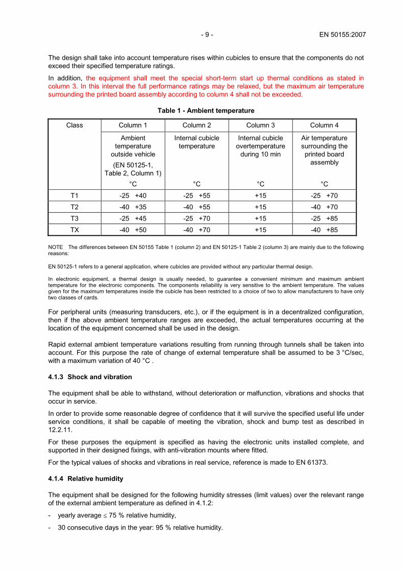
The design shall take into account temperature rises within cubicles to ensure that the components do not exceed their specified temperature ratings.
In addition, the equipment shall meet the special short-term start up thermal conditions as stated in column 3. In this interval the full performance ratings may be relaxed, but the maximum air temperature surrounding the printed board assembly according to column 4 shall not be exceeded.
Table 1 - Ambient temperature
Column 1 Column 2 Column 3 Column 4 Class
Ambient temperature
outside vehicle
(EN 50125-1, Table 2, Column 1)
°C
Internal cubicle temperature
°C
Internal cubicle overtemperature
during 10 min
°C
Air temperature surrounding the printed board
assembly
°C
T1 -25 +40 -25 +55 +15 -25 +70
T2 -40 +35 -40 +55 +15 -40 +70
T3 -25 +45 -25 +70 +15 -25 +85
TX -40 +50 -40 +70 +15 -40 +85
NOTE The differences between EN 50155 Table 1 (column 2) and EN 50125-1 Table 2 (column 3) are mainly due to the following reasons: EN 50125-1 refers to a general application, where cubicles are provided without any particular thermal design. In electronic equipment, a thermal design is usually needed, to guarantee a convenient minimum and maximum ambient temperature for the electronic components. The components reliability is very sensitive to the ambient temperature. The values given for the maximum temperatures inside the cubicle has been restricted to a choice of two to allow manufacturers to have only two classes of cards. For peripheral units (measuring transducers, etc.), or if the equipment is in a decentralized configuration, then if the above ambient temperature ranges are exceeded, the actual temperatures occurring at the location of the equipment concerned shall be used in the design. Rapid external ambient temperature variations resulting from running through tunnels shall be taken into account. For this purpose the rate of change of external temperature shall be assumed to be 3 °C/sec, with a maximum variation of 40 °C . 4.1.3 Shock and vibration The equipment shall be able to withstand, without deterioration or malfunction, vibrations and shocks that occur in service.
In order to provide some reasonable degree of confidence that it will survive the specified useful life under service conditions, it shall be capable of meeting the vibration, shock and bump test as described in 12.2.11.
For these purposes the equipment is specified as having the electronic units installed complete, and supported in their designed fixings, with anti-vibration mounts where fitted.
For the typical values of shocks and vibrations in real service, reference is made to EN 61373. 4.1.4 Relative humidity The equipment shall be designed for the following humidity stresses (limit values) over the relevant range of the external ambient temperature as defined in 4.1.2:
- yearly average ≤ 75 % relative humidity,
- 30 consecutive days in the year: 95 % relative humidity.
EN 50155:2007 - 10 -
In addition, any moisture condensation shall not lead to any malfunction or failure.
For peripheral units (measuring transducers etc.), or if the equipment is in a decentralized configuration, then if the above humidity stresses are exceeded, the actual humidity occurring at the location of the equipment concerned shall be used in the design. 4.2 Special service conditions Special arrangements shall be agreed between the appropriate parties involved when service conditions can be proved to be different from those mentioned in 2.1 (e.g. electronic equipment mounted on the bogie or integrated within a power converter etc.). Checks for the effectiveness of such arrangements can, if required, form the subject of optional type tests which can be carried out on the vehicle itself in accordance with methods to be agreed between the user and the manufacturer. 4.2.1 Atmospheric pollutants The equipment may be expected to be exposed throughout its life to various pollutants (e.g. oil mist, salt spray, conductive dust, sulphur dioxide.). The types of pollutants and their concentration should be defined in the tender documents. 5 Electrical service conditions 5.1 Power supply 5.1.1 Supply from accumulator battery The nominal voltage of equipment (Un) so supplied shall be selected from amongst the following values: 24 V, 48 V, 72 V, 96 V, 110 V NOTE 1 These nominal voltage values are given only as standardising values for the design of equipment. They should not be considered as the off load battery voltages since these are determined by the types of battery, the number of cells and the operating conditions. NOTE 2 Different voltage variations may be used, following EN 60077. In this case compliance with the requirements should be defined by agreement between manufacturer and user. 5.1.1.1 Variations of voltage supply Electronic equipment supplied by accumulator batteries without a voltage stabilizing device shall operate satisfactorily for all the values of the supply voltage within the range defined below (measured at the input terminals of the equipment).
The supplier of the electronic equipment shall specify its power consumption in order to enable calculations for the battery cabling. Minimum voltage: 0,7 Un
Nominal voltage: Un
Rated voltage: 1,15 Un
Maximum voltage: 1,25 Un
Voltage fluctuations (e.g. during start-up of auxiliary equipment or voltage oscillations of battery chargers) lying between 0,6 Un and 1,4 Un and not exceeding 0,1 s shall not cause deviation of function.
Voltage fluctuations lying between 1,25 Un and 1,4 Un and not exceeding 1 s shall not cause damage: equipment may not be fully functioning during these fluctuations.
In the case of thermal engines, see also 5.1.1.3.
- 11 - EN 50155:2007
5.1.1.2 Interruptions of voltage supply Interruptions of up to 10 ms may occur on input voltage as defined below:
- Class S1: no interruptions
- Class S2: 10 ms interruptions This shall not cause any equipment failure. The time values specified are for nominal voltage and the choice of classes shall be defined by the system designer. 5.1.1.3 Variations of voltage supplies for rolling stock powered by thermal engines At start-up of thermal engines the voltage supply system shall be designed to guarantee the supply to the essential electronic equipment during the whole starting sequence. 5.1.1.4 D.C. ripple factor All batteries on charge have a pulsating voltage, the d.c. ripple factor of which, unless otherwise stated, shall not be greater than 15 % calculated from the equation: Umax - Umin d.c. ripple factor = x 100 Umax + Umin where Umax and Umin are the maximum and minimum values, respectively, of the pulsating voltage. The minimum and maximum voltages as defined in 5.1.1.1 however shall not be exceeded. 5.1.2 Supply by a static converter or a rotating set In the case of equipment supplied with power from a stabilized source, (e.g. a static converter or a rotating motor-generator set provided with a regulator), electronic equipment shall operate satisfactorily for values of the supply voltage lying between 0,9 and 1,1 Un, where Un is the nominal voltage and can be either d.c. or a.c.
In addition, for operating equipment, voltage fluctuations lying between 0,7 Un and 1,25 Un not exceeding 1 s and also between 0,6 Un and 1,4 Un not exceeding 0,1 s are allowed. 5.1.3 Supply change over In the case of equipment supplied with power alternatively from an accumulator battery and a stabilized source (d.c.), the equipment shall operate satisfactorily under the conditions stated in 5.1.1, 5.1.1.1, 5.1.1.4 and 5.1.2.
- Class C1: at 0,6 Un during 100 ms (without interruptions).
- Class C2 during a supply break of 30 ms.

EN 50155:2007 - 12 -
5.1.4 Supply with overhead line or third rail In the case of electronic equipment with a supply derived directly from the overhead line or third rail (e.g. control electronics of a self starting static converter), the equipment shall operate satisfactorily for values of contact line voltage as described in EN 50163. 5.2 Supply overvoltages All connections to electronic equipment capable of being connected to the control system voltage supply shall withstand:
a) the supply overvoltages as specified in 5.1.1.1 and/or 5.1.2 (as appropriate);
b) the application of supply overvoltages as specified in 12.2.6.
Overvoltages shall be assumed to be generated with respect to the control system voltage supply return potential and to be present only as an increase to the level of the control system voltage, which shall be assumed to be present before and after the application of the overvoltage. Overvoltage of opposite polarity to the control system voltage supply need not be considered.
Overvoltage exceeding 1,25 Un longer than 0,1 s shall be assumed to occur only in the case of a failure in the control system voltage supply. 5.3 Installation The supply to the electronic equipment should be provided by a separate conductor connected as directly as possible to the source. This conductor should be used only for the supply to electronic circuits.
The installation of the electronic equipment shall be arranged so as to reduce, as far as possible, the effects of external electrical disturbances.
Suppression should be provided at the source of electrical interference.
If one pole of the battery of the vehicle is connected to the vehicle body, this shall be specified.
Where several manufacturers supply electronic equipment having common direct connections, a single reference point of equi-potential shall be established by mutual agreement. 5.4 Surges, electrostatic discharge and transient burst susceptibility tests All electronic equipment shall withstand surges, electrostatic discharge and transient burst susceptibility tests as specified in EN 50121-3-2.
The tests are specified in 12.2.7 5.5 Electromagnetic compatibility The equipment shall be protected so as not to be adversely affected by conducted or radiated interference as required in EN 50121-3-2 and shall not emit radio frequency interference (RFI) in excess of the level defined in EN 50121-3-2.
The tests are specified in 12.2.8. 6 Reliability, maintainability and expected useful life 6.1 Equipment reliability 6.1.1 Predicted reliability The user may require the manufacturer to predict his reliability figure or meet the user's reliability target. The method of calculation shall be agreed at the time of tendering between the manufacturer and the user, and shall be in accordance with a recognized standard.

- 13 - EN 50155:2007
6.1.2 Proof of reliability Where the user has specified a required reliability level, the following actions are necessary.
The equipment performance shall be carefully monitored.
The equipment manufacturer and the user shall agree to record all actions carried out on the equipment.
To demonstrate the reliability level of the equipment a defect report will be presented at the end of a mutually agreed period (km or service hours) identifying the components replaced (circuit reference number, type, manufacturer, number of manufacturing lot, kilometres and/or operating hours etc.), the definition and cause of faults (design weakness, software, component problems etc.).
In order to show whether the equipment meets its stated reliability requirements, the equipment should be subjected to a reliability evaluation.
IEC 60605 may be used as a guide.
The detailed reliability evaluation procedure shall be stated in the contract. 6.2 Useful life The useful life of the electronic equipment, unless otherwise agreed at the time of tendering between the equipment manufacturer and the user, shall be taken as 20 years.
When the manufacturer intends to use components with a known life less than the useful life of the electronic equipment, their use and procedures for their regular replacement shall be agreed between the involved parties. 6.3 Maintainability Unless otherwise agreed, equipment shall be designed such that regular periodic maintenance shall not be necessary.
Special maintenance requirements, if any, shall be defined by the user at the time of tendering.
Printed board assemblies, and/or subracks shall be capable of being individually tested.
In addition, the equipment manufacturer shall advise what maintenance procedures are necessary or prohibited. NOTE Maintenance processes such as ultrasonic cleaning, connecting of diagnostic test equipment, electrical insulation testing, and transportation packaging arrangements, can reduce the equipment reliability level, through additional stressing of the assembly and components. 6.4 Maintenance levels 6.4.1 On-vehicle diagnosis and repair The user and manufacturer shall agree on the nature of units (e.g. subracks or plug-in units) to be exchanged as a result of on-vehicle fault diagnosis.
These units, defined as line replaceable units, shall be designed to be easily exchanged.
The user and manufacturer shall also agree on the use of any specialised tools required in this maintenance procedure.
Equipment shall be designed such that a failed line replaceable unit can be identified by the use of either suitable portable test equipment or built-in diagnostics, both with associated test instructions.
Maintenance or diagnostic procedures at this level shall not require the removal or replacement of any component of the Line Replaceable Unit.
EN 50155:2007 - 14 -
6.4.2 Off-vehicle diagnosis and repair Equipment shall be designed such that test equipment with associated test instructions shall enable the full diagnosis and validation of performance of each type of train-borne equipment in repair centres by qualified personnel.
Equipment shall be constructed such that access necessary for diagnosis and repair can be achieved without damage or undue disturbance to the components or wiring.
In addition, printed board assemblies shall have test facilities (e.g test plugs, test pads etc.) to aid the diagnosis and repair process. 6.5 Built-in diagnostics Indicators to assist diagnostic maintenance shall be used where appropriate, in order to display status of input data, output data, main control functions, power supplies, etc.
Self test routines shall be capable of providing clear indication of the operational status of the equipment.
Any built-in diagnostic facilities capable of exercising rather than monitoring the equipment shall be suitably interlocked to prevent interruption of the normal operation of the equipment other than under test conditions.
The use of extra components for built-in diagnostics shall not considerably influence the reliability of the equipment, and shall be taken into account in reliability calculations. 6.6 Automatic test equipment The user may require to use a specific type of automatic test equipment for fault location either on or off the vehicle.
If this is required, details of such test equipment and its interfacing with train-borne equipment, e.g. bed of nails or guided probe (for off-vehicle repair), or equipment connector (for on vehicle diagnosis), shall be provided by the user at the time of tendering.
It is permitted to remove plug-in units which do not contribute to the function of the equipment, to facilitate the connection of Automatic Test Equipment. 6.7 Alternative methods for fault diagnosis Where train-borne electronic equipment has been developed or tested using proprietary test equipment the manufacturer may offer this as an alternative for fault diagnosis within repair centres, provided that use of such equipment is practical to the installation and all support details are made available to the user. 6.8 Purpose built test equipment and special tools The prior approval of the user shall be obtained regarding the use of items requiring tools other than readily available industrial tools.
Where purpose built test equipment and/or special tools are required to carry out the user's formal maintenance procedures, this equipment, or alternatively the manufacturing and procurement details for it, shall be offered for sale to the user.
Test equipment does not necessarily have to comply with this standard.
- 15 - EN 50155:2007
7 Design 7.1 General 7.1.1 Quality management All design shall proceed according to EN ISO 9001.
The design process shall be visible and auditable.
If the user requires details of this process for tender evaluation, he shall define this in the tender documents.
Particular attention is drawn to the need implicit in the use of EN ISO 9001, for all system, hardware, and software design to proceed according to clearly laid down functional and interface specifications. 7.1.2 Life-cycle All design shall proceed according to a defined life cycle model, which shall be laid down in the quality plan. 7.2 Detailed practices - Hardware 7.2.1 Interfacing All interfaces shall be so implemented as to allow the equipment to meet its requirements in respect of: - electromagnetic compatibility; - potential differences; - personnel safety and to control propagation of damage arising from external faults.
The user may require galvanic isolation to meet the above. In this case the requirement and particular areas for its application shall be declared at the tender stage.
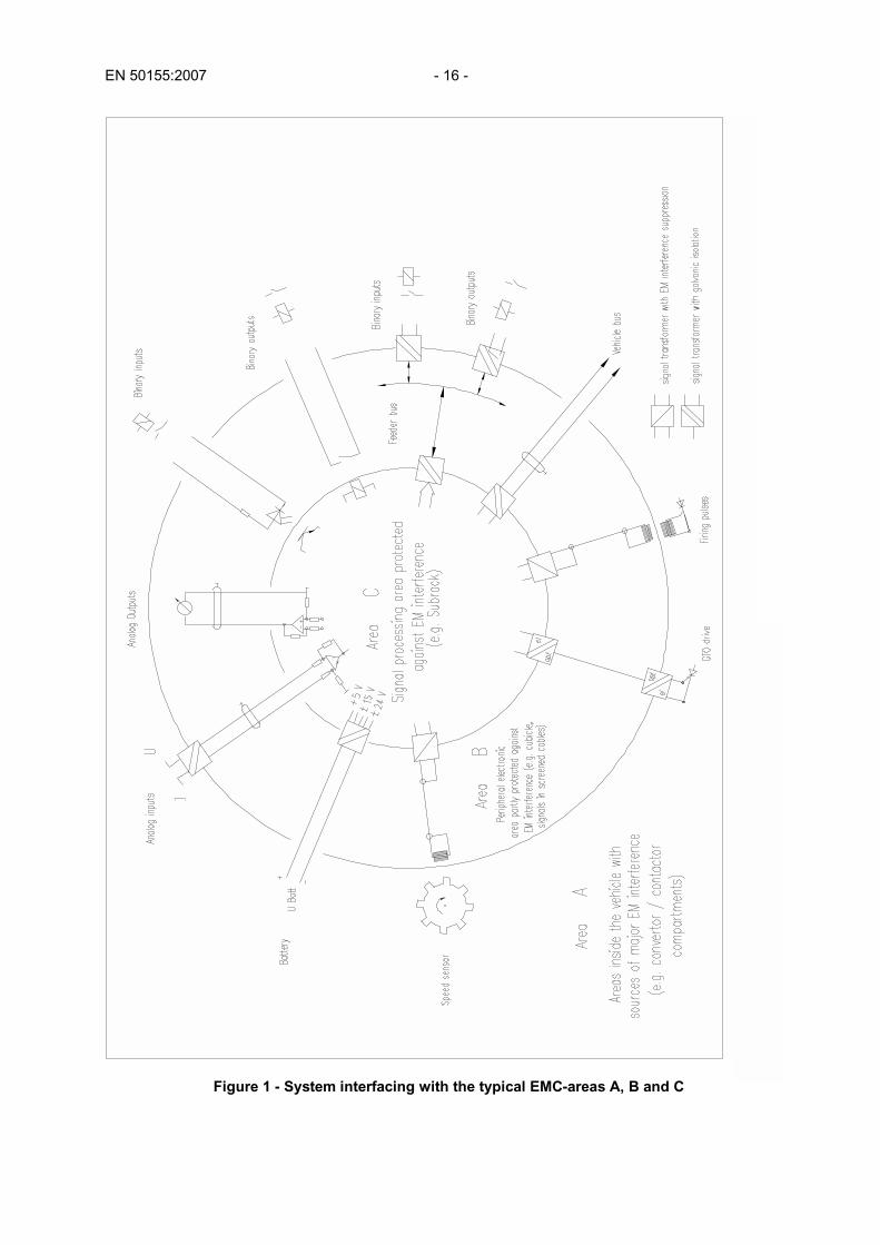
An example of system interfacing with various EMC areas is given in Figure 1. 7.2.2 Fault protection Outgoing cables shall be rated to at least the current limit value of the protective device for that circuit.
Equipment shall be protected against external faults (e.g. short circuit or open circuit conditions as appropriate).
Regulated power supply units for electronic equipment shall incorporate current limiting to minimise the use of fuse elements.
If the user wishes to forbid the use of fuses internal to the equipment, this shall be declared at the time of tendering.
EN 50155:2007 - 16 -
Figure 1 - System interfacing with the typical EMC-areas A, B and C

- 17 - EN 50155:2007
Where protective devices of the tripping type are incorporated in the output circuits, the available current under short circuit conditions shall be sufficient to operate them. In addition, devices with manual resetting shall be easily accessible.
Any protective devices used shall be so arranged that the risk of fire within the equipment is minimised. 7.2.3 Referencing power supplies The output of galvanically isolated power supply units should not be allowed to float.
When the outputs are not referenced to a voltage source (e.g. battery or voltage supply) then one of the supply rails should be connected to the vehicle frame or a defined earth point.
This reference and the means of connection should be defined and mutually agreed. 7.2.4 Interchangeability All individual printed board assemblies forming part of a system shall be functionally complete and fully interchangeable with any other unit of the same functional type without the need for any recalibration of the hardware after the board has been inserted in the system. 7.2.5 Reduction of supply voltage The equipment shall not suffer damage, when the supply is, or falls, below the lowest limit of its specified source voltage, irrespective of the rate at which the voltage changes.
In addition, the equipment shall not generate any spurious output which could lead to consequential failure of any other equipment under these conditions. 7.2.6 Polarity reversal To prevent any damage to the equipment, electrical or mechanical means shall be provided to ensure protection against polarity reversal of the incoming power supply. 7.2.7 Inrush currents The design of the equipment shall take account of inrush currents which may occur at the time of switch-on, so that protective devices do not trip and no damage occurs. 7.2.8 Spare capacity If the user requires spare capacity (e.g. spare inputs, spare outputs, CPU loading, etc.) for system expansion or changes during the equipment life-cycle, he shall specify this at the tender stage. Compliance with these requirements shall be included in the design process. 7.3 Detailed practices - Software 7.3.1 General EN 29000-3 shall be used for the application of EN ISO 9001 for software.
Requirements and recommendations of EN 29000-3 shall have mandatory effect.
Configuration management procedures shall run in parallel with life-cycle activities covering all the software and tools used for its development and its maintenance.
Life-cycle issues and documentation of the software development shall be covered.
The development of the software shall be structured into defined phases and activities.
All information pertinent to the design of the software shall be recorded.

EN 50155:2007 - 18 -
Minimum phases and required documents are the following: a) Software requirements phase
In this phase all the requirements of the software shall be captured and documented in a software requirements specification, including interfaces to the system environment and to the other softwares.
b) Software design phase
In this phase, the architecture of the software shall be defined, the modules specified and the code written, ensuring that all elements meet the requirements as defined in the software requirements specification. In addition 5.3.2 should be taken into account.
c) Software testing phase
This phase covers the testing of the software at each of its design levels to ensure its correctness and consistency with respect to its specification. Test results shall be recorded.
d) Software/hardware integration phase
In this phase the hardware and software shall be integrated and tested to ensure compliance with the requirements of the system (e.g. as defined in the software requirements specification). Test results shall be recorded.
e) Software maintenance phase
It is important that the dependability of the software is not compromised when making corrections, enhancements or adaptations. The measures taken shall be defined and documented.
7.3.2 Software design measures The following measures shall be used, unless the rationale for any alternative has been documented and agreed with the user. NOTE Explanations on these and other useful measures may be found in EN 50128 (Annex B). 7.3.2.1 Modular approach The software shall be broken down into small comprehensible parts in order to manage its complexity. That includes taking measures such as module size limitation and fully defined interface. 7.3.2.2 Translator proven in use A translator proven in use shall be applied to avoid any difficulties due to translator failures which can arise during development, verification and maintenance of a software package. 7.3.2.3 Recording All data, decisions and rationale in the software project shall be recorded to allow for easier verification, validation, assessment and maintenance. 7.3.2.4 Structured methodology Structured methods shall be applied to promote the quality of software development by focusing attention on the early parts of the life-cycle. The methods aim to achieve this through both precise and intuitive procedures and notations (assisted by computers) to identify the existence of requirement and implementation features in a logical order and a structured manner.

- 19 - EN 50155:2007
7.3.2.5 Design and coding methods Design and coding methods shall be defined to ensure a uniform layout of the design documents and the produced code, as well as enforcing egoless programming and a standard design method. 7.3.2.6 Structured programming and analysis The program shall be designed and implemented in such a way as to facilitate the analysis of the program.
The program behaviour shall be testable completely on the basis of the analysis. 7.3.2.7 Programming language The programming language chosen shall facilitate the verification of the code with a minimum of effort and aid program development verification and maintenance. 7.3.2.8 Proven techniques Proven techniques shall be used. Examples of such techniques include:
a) semiformal methods, e. g.:
- logic/function block diagrams;
- sequence diagrams;
- data flow diagrams;
- decision/truth tables; b) testing methods, e. g.:
- boundary value analysis;
- equivalence classes and input partition testing;
- process simulation;
7.4 Equipment features The equipment shall be constructed with the following features, intended to provide operation under all conditions. 7.4.1 Memory checking Upon power up, during its initialisation, the equipment shall perform a check to show that:
a) All required memory is present and functional
b) All program memory, which may be split between individual integrated circuits or printed board assemblies is functionally compatible.
Means to relate memories to the correct printed board assembly, and printed board assemblies to the subrack, shall be provided either by visual indication on the body of the device or by internal coding. The method shall be declared to the user. 7.4.2 Self test The equipment shall include a self test function which shall, as far as practicable, verify that the system is operational at each initialisation. As far as possible in the event of self test failing, diagnostic information shall be made available to indicate the area of the fault. Where possible the system shall enter the recovery state.

EN 50155:2007 - 20 -
7.4.3 Watchdog The equipment shall include a watchdog function, to cause it to enter a recovery state in the case of failure of the operational software (e.g. software entering an unintended loop due to abnormal transient disturbances). 7.4.4 Error indication On detection of errors the processor shall record or indicate that such an event has occurred. It shall then enter a recovery state. 7.4.5 Recovery The equipment shall, as far as possible, recover from any fault or error state, into which it may be forced, with the minimum disruption to its functions. This recovery may require the processor to re-initialise. Where it is not safe or practicable to recover from this state, the manufacturer shall declare the effect on the equipment. 8 Components 8.1 Procurement 8.1.1 All components shall comply with detail specifications which define the component functional and physical parameters. 8.1.2 All components used shall have been manufactured according to a quality system compliant with the requirements of EN ISO 9001 or EN ISO 9002 as relevant, or an equivalent quality system. 8.1.3 The component specifications referenced above shall be in accordance with one of the standards or documents listed below:
a) EN or IEC specifications;
b) other national or international standards or specifications;
c) Specification of the component manufacturer;
d) Specification of the equipment manufacturer; Wherever possible in cases c) and d), the documents shall refer to EN or IEC generic specifications. 8.1.4 Except as provided for in 8.1.5, components with a multiple source of supply shall be used. For the purpose of this standard, "multiple sourcing" shall imply complete interchangeability in respect of fit and function according to the specification detailed in 8.1.1 above. 8.1.5 Where single source components cannot be avoided, this shall be justified and be drawn to the attention of the user at the tender stage. 8.1.6 The components and the families of components used shall be chosen on the basis of a high probability that further supplies will be available for at least half of the agreed useful life of the electronic equipment as defined in 6.2. If, despite these precautions, certain components should become unavailable during the period covered by the equipment supply contract, the manufacturer of the electronic equipment shall provide an alternative solution. 8.1.7 Specialised components such as custom hybrid circuits and application specific integrated circuits (ASIC), shall be subject to a detail specification sufficiently precise to allow subsequent redesign or sourcing of a completely interchangeable device from an alternative supplier.
- 21 - EN 50155:2007
8.2 Application 8.2.1 All components used shall be of such a grade as to be appropriate for use in the application, and subject to the requirements (e.g. environment, quality, life expectancy, etc.) described in this standard. 8.2.2 For components or technology which have no history of rail application, the user may require evidence that these components or technology comply with the requirements of this standard. 8.2.3 All components shall be used:
a) in accordance with the component manufacturers basic specifications
b) in such a manner as not to compromise the equipment life or performance. 8.2.4 The choice of temperature range, derating, packaging and screening etc. of components is the complete responsibility of the manufacturer.
If required by the user, the manufacturer shall demonstrate (e.g. by calculations or other applications), at the time of tendering, that the equipment fulfils all the requirements given in this standard with particular reference to reliability and the life of components as described in Clause 4. The life expectancy of components shall not be less than the useful life of the equipment except for components with a known life as defined in 4.2. 9 Construction 9.1 Equipment construction Equipment shall comply with the following constructional requirements. 9.1.1 Mechanical protection It shall be possible to lay on a flat surface all line replaceable units (LRU) on any of their faces without causing mechanical damage to any component. Where necessary, mechanical guards shall be fitted. 9.1.2 Polarisation or coding Where required by the user, all line replaceable units (LRU) shall incorporate mechanical means of polarisation or coding to prevent incorrect insertion. 9.1.3 Dimensional requirements Racks, subracks, and plug-in units shall comply with the dimensional requirements of EN 60297/HD 493. NOTE The most commonly used dimensions of EN 60297/HD 493 are 3U and 6U with printed board depths 160 mm or 220 mm. 9.1.4 Sockets and connectors At the time of tendering the user may prohibit the use of integrated circuit sockets and/or edge connectors. 9.2 Component mounting Equipment shall comply with IEC 60321 and the following constructional requirements.

EN 50155:2007 - 22 -
9.2.1 Layout Component parts shall be so located, secured and disposed with respect to each other and the structural members so that they can be inspected, removed and replaced without damage to or undue disturbance of other parts or wiring.
Wherever possible, the marking on the fitted component shall be visible.
Equipment shall not be designed to have components attached to wiring terminal blocks unless adequate clamping or an auxiliary printed board assembly is provided and component identification is preserved.
Heat dissipating components shall be mounted so that they will not cause damage to printed boards or any other components. 9.2.2 Fixing Components which do not have specific mechanical fixings, whose weight may through vibration during the life of the equipment cause stress or damage to the soldered connections, shall be secured to the printed board.
The method of securing shall be such that they can be replaced without damage to the printed board.
All components shall be mounted in accordance with the component manufacturer's recommendations or, in the absence of such recommendations, in such a way that the method of fixing has no adverse effect on the performance of the component or unit, including the soldered joints. 9.2.3 Component terminations Connections to components shall be made such that no mechanical or thermal stress exceeds the limits specified for the component.
Bending of component leads shall not cause damage or permanent stress to the component body/lead junction. 9.2.4 Pre-set control Where pre-set controls have been deemed necessary for operating adjustments (i.e. not internal calibration), they shall be accessible with the complete equipment and adjacent equipments in operation.
Such controls shall retain their settings in normal operation and shall be protected against accidental adjustment. 9.2.5 Select on test (SOT) components. Where SOT components are used they shall be soldered to component mounting posts to facilitate removal for recalibration purposes. 9.3 Electrical connections Connections shall be of the following types. 9.3.1 Soldered connections Soldered connections shall be made only to components specially designed for that purpose. Flexible/stranded conductors and metallic braiding designed for flexing shall not be soldered but fitted with crimped tags and strain relieved before the electrical connections.
Silver or gold plated wires or components shall not be soldered, unless the plating is thin enough to avoid any adverse effect on the joints.
Soldered wires and components shall as far as possible be capable of disconnection without disturbing other connections.
Solder fluxes shall be non-corrosive.

- 23 - EN 50155:2007
9.3.2 Crimped connections Crimped connections shall be in accordance with EN 60352-2. 9.3.3 Wire wrap connections All wire wrap connections shall, as a minimum, comply with EN 60352-1 and be of the modified type. Soldered and wrapped wire connections on the same post are not allowed. The wire used shall be suitable for the chosen wrapping process, and at least three turns of the wire shall be in close contact. 9.3.4 Other connections Other methods of connection e.g. insulation displacement, press-fit, etc. shall only be used by prior agreement with the user. 9.4 Internal flexible wiring (electrical and optical) Wiring which could be subjected to flexing shall be provided with suitable clamps, sheaths or supports adjacent to the terminations and at suitable locations along its route.
Wiring shall be so arranged that its performance shall not be affected by extremes of temperature.
Wiring shall not be bent to a radius less than the minimum permissible value specified by its manufacturer. Where a minimum radius is not specified, for electrical cable, the inside radius of the bend shall not be less than the overall diameter of the wire including its insulation.
Grommets, bushes or edge protections shall be fitted where wiring passes through any material likely to cause abrasion damage.
Internal wiring shall be adequately supported by clamping, looming, troughing, or similar means.
Wiring shall be clamped into plugs and sockets in such a way that the connections inside the connector cannot be subjected to detrimental tensile or torsional stress by normal operation and handling.
Where practical, sufficient wire shall be provided to enable a re-connection to be made at each end of the wire.
Screened cables shall have an insulating sheath.
All wiring shall be readily traceable to a point-to-point wiring diagram or list. 9.5 Flexible printed wiring Flexible printed wiring shall not carry components other than connectors.
The base material shall have suitable temperature ranges and mechanical properties to suit the application. It shall be flame retardant and drip proof.
Wherever possible sharp bends shall be avoided. The minimum bending radius shall not be so small that it results in cracking or deterioration of the base material or the overlay.
Adequate support to any transition termination shall be provided to ensure that separation of the base material or underlay does not occur.
Any termination using this technique shall be capable of re-connection without damage to the wiring system.

EN 50155:2007 - 24 -
9.6 Printed boards - flexible and rigid 9.6.1 Printed board types The following types of printed board may be used:
- rigid single or double-sided;
- flexible and flexirigid single or double-sided;
- rigid multilayer.
Unless specific protection against external fault conditions are taken, signal tracks on inner layers shall not be used for direct connection to the vehicle wiring. All the holes used for soldered connections shall be plated through, with pads on both sides.
Other types may be used with prior approval of the user. 9.6.2 Procurement Printed boards shall be procured and manufactured according to the provisions of the relevant Specification from the list below:
- EN 123000 (Generic Specification - Printed boards);
- EN 123200 (Sectional Specification - Single and double sided printed boards with plain holes);
- EN 123300 (Sectional Specification - Multilayer printed boards);
- EN 123400 (Sectional Specification - Flexible printed boards without through connections);
- EN 123500 (Sectional specification - Flexible printed boards with through connections). Alternative standards of equivalent scope may be used with prior approval of the user. 9.6.3 Layout Board layout shall be carried out according to EN 62326, with due regard to the service conditions of this standard. 9.6.4 Materials The base material shall be an epoxide woven glass fabric laminated sheet of defined flammability (vertical burning test) for rigid printed boards and for use in the fabrication of multilayer printed boards, according to EN 61249-2-7, EN 61249-2-10 and EN 62326, as appropriate.
For flexible printed boards the base material shall be a flexible copper-clad polyimide film of defined flammability (vertical burning test), according to EN 60249-2-15.
Other materials may be used providing they meet or exceed the performance of base material specified above. 9.7 Protective coatings for printed board assemblies All printed board assemblies shall be protected on both sides with a protective transparent coating, in order to prevent deterioration or damage due to such causes as moisture and atmospheric contaminants. The coating shall not have any adverse reaction with any other materials or components used.
The protective coating shall not be applied to IC sockets, test points or to connector contact mating surfaces, etc.
It shall be possible to repair a coated printed board assembly without the need for complete removal of the coating.
After repairing, the printed board shall be locally recoated.

- 25 - EN 50155:2007
9.8 Identification 9.8.1 Bare printed board identification The artwork shall reproduce sufficient information to enable its correct identification including its revision. 9.8.2 Identification of subracks and printed board assemblies Labelling of subracks and printed board assemblies shall be adequate to enable their correct identification including serial number and revision. All labels shall be clear, bold, concise and durable.
Labelling of line replaceable unit (LRU) shall also include its identification name, manufacturer's name or trade mark, and serial number.
Means shall be provided on the subracks and printed board assemblies to record any change to fit, form or function.
Where possible the identification label shall be placed on the front panel of plug-in units.
For maintenance purposes it is also desirable that the modification label be fitted to this front panel. 9.8.3 Mounting position of subracks and printed board assemblies Each mounting position shall be marked to indicate the type of subrack, printed board assembly or cable connectors to be located in that position. 9.8.4 Fuse and battery identification All fuse ratings shall be indicated adjacent to the fuse.
Where batteries are used internal to the equipment, the front panel of the module in which they are placed shall be marked to indicate their presence and to show the recommended date of replacement. 9.9 Mounting The equipment shall be mounted in some way to ensure its ability to operate in the specified service conditions. Such mounting may comprise:
- for major equipment: a cubicle, a number of racks, subracks and printed board assemblies;
- for smaller, localized equipments: individual sealed enclosures. In each case, the enclosure shall provide the necessary protection (IP code according to EN 60529) from the service conditions, and permit dismantling and repair of the contained equipment. Encapsulation (the covering of, for example, a printed board assembly with silicon rubber, resin or other material) to provide additional protection is not preferred and shall only be used where (for example in the case of a remotely mounted transducer) special environmental conditions dictate it. If the manufacturer intends to use encapsulation, he shall advise the user at the earliest possible stage. NOTE The requirements of this clause do not include individual components such as hybrid circuits, ASICs, etc. 9.10 Cooling and ventilation Cooling shall not be achieved by the forced induction of air into the equipment enclosure, unless precautions agreed between involved parties are taken to ensure that the life of the equipment is not thereby adversely affected by the introduction of contaminants.
Where fan assisted cooling is used, the equipment shall be protected so that no damage occurs due to the failure of the cooling system. The full performance specification shall be maintained until the related protective device operates.
(Damage in this context includes effects on the equipment life due to the operation of any component beyond its maximum specified ratings).
EN 50155:2007 - 26 -
9.11 Materials and finishes Materials and finishes shall be suitable for the conditions of use, and shall be chosen with respect to the environmental, wear and ageing factors, as well as to the risk of toxic influences on persons.
All materials shall be dimensionally stable, non-hygroscopic, resistant to fungal growth and either non-ignitable or resistant to flame propagation.
The user shall provide a list of materials which are forbidden or controlled by national law.
In addition, the manufacturer shall specify the method of disposal of any component which contains toxic material. 10 Safety These provisions relate to both the main equipment and any maintenance equipment, tools or procedures. 10.1 General Equipment shall be designed, constructed and installed (as relevant to the contract), in full accordance with the current National Safety legislation of the country or countries of use, as defined by the user. 10.2 Functional safety Safety related functions for the equipment or system and their specific safety integrity requirements shall be defined in accordance with EN 50126 (Subclauses 4.3, 4.6 and 4.7). NOTE Safety integrity level for any software associated with a safety related function is dependant on the level of external risk reduction measures or protective systems applied to that function. For example: a hard wired “fail safe” circuit or a “fail safe” mechanical device. Where all safety risk is covered by such measures, then the associated software is not safety related and classed as safety integrity level zero. 10.3 Personnel safety The user shall identify any special requirements related to personnel safety, in respect of equipment, construction and use of materials, at the time of tendering. 11 Documentation As referenced in Clause 7, the equipment design shall be documented according to the provisions of EN ISO 9001. 11.1 Supply and storage of documentation The supplier and user shall agree in writing:
a) the quantity, scope, content, presentation, medium and updating process of documentation required by the user,
b) the scope, conditions and duration applying to the storage of documentation by the supplier.
Such written agreement shall be considered only if contained within the contract. 11.2 Hardware and software documentation The following items provide a check list for documentation which might reasonably be expected to be required by the user.

- 27 - EN 50155:2007
11.2.1 Hardware documentation The following items provide a check list for hardware documentation:
a) equipment name and type;
b) functional purpose of the equipment;
c) composition of the complete equipment;
d) principle of operation;
e) commissioning instructions and pre-setting data;
f) description of circuit operation, including voltage, current waveforms, and rise times, etc. where appropriate;
g) functional interface description;
h) modification status;
i) certain manufacturing documents (circuit diagrams, wiring diagrams, etc.);
j) on/off vehicle diagnostic procedures and test equipment required;
k) storage precautions;
l) annotated functional block diagram;
m) layout diagrams and mechanical arrangement drawings;
n) component list;
o) component specifications and sourcing (i.e. manufacturer) information;
p) test points;
q) list of limited life components;
r) information relating to any hazardous materials which may be present in the equipment and which were approved by the user;
s) information relating to any implosion or explosion hazards which may exist within the equipment or which may occur in use or in handling;
t) maintenance documentation. 11.2.2 Software documentation The following items provide a check list for software documentation:
a) a software requirement specification describing the manufacturer's approach to the requirement specifications for the system;
b) a software description indicating the architecture and design of the software to meet the software requirement specification;
c) for each module:
- the performance description (e.g. input, output, function),
- the written source code (assembler or high level as appropriate),
- test requirements and test results;
d) data dictionary, which defines all global variables and global constants;
e) the system memory map;
f) the hardware dependency (i.e. hardware requirements for the software);
g) details of development system used;
h) reference details of any tools used to develop the software;
i) integration test requirements and results;
j) maintenance documentation.

EN 50155:2007 - 28 -
11.3 Documentation requirements 11.3.1 Documents All documents submitted to the user shall bear an appropriate drawing number, date, version/release and title indicating the particular item shown and the type of drawing.
All documents and components lists shall have an issue or revision index and a record of modification.
All graphical symbols shall comply with IEC 60617. 11.3.2 Circuit diagrams Circuit diagrams shall be generated for each printed board assembly, and plug-in unit of the complete equipment.
Where practicable, all circuit diagrams shall be drawn so that the main sequence of events on the signal path is from left to right (and where necessary for arrangement purposes, from top to bottom).
Wherever practical, the circuit diagram for any one unit shall be completely self-contained, self-explanatory, readily related to other circuit diagrams and shall show: - supply voltage levels and interconnections, - connections between the low voltage circuits, - connections between these circuits, the electronic equipment, the transducers and the controlled or
monitored devices, - earth connections of the metallic parts, - connections between the electronic zero volt lines, - casings and their connections, - screened or twisted cables. Discrete components external to a printed board assembly or plug-in unit but essential to its operation shall be shown in dotted outline on the circuit diagram and be appropriately identified.
All component symbols shall be marked with their circuit references and the nominal value of components shall be marked on the circuit diagram where the component list is not included on the same diagram.
Components with three or more connections shall have the connection points identified or marked.
The function of all controls, switches and indicating devices shall be indicated in accordance with the inscriptions marked on the equipment. The symbols for rotary controls shall be marked with an arrow indicating clockwise rotation of the spindle when viewed from the operating end.
Relays shall always be shown in the de-energised position. 11.3.3 Component lists Component lists shall uniquely identify for each component its reference number and the specification of that component. 11.3.4 Component layout Component layout drawings shall show the location of each individual component used in a printed board assembly or plug-in unit, marked with its circuit reference number, outline and polarising details where used.

- 29 - EN 50155:2007
11.3.5 Block diagrams Block diagrams with symbols conforming to IEC 60617 and EN 61082 series shall show the flow of information between the identifiable parts of a system. 11.3.6 Wiring diagrams Wiring diagrams and charts shall show the inter-unit wiring within equipment enclosures and, in addition, the services provided (i.e. supplies, distribution, alarms, etc.). 11.3.7 Interconnection diagrams Interconnection diagrams and charts shall show the necessary connections between equipment enclosures and all items connected to the equipment by means of external cables.
They shall also show the type of cable to be used for these connections and any special arrangements for terminating or special wiring arrangements to reduce interference. 11.3.8 Equipment drawings Equipment drawings shall show the layout of equipment mounted in racks or subracks, the disposition of units and sub-units within an enclosure, and the essential mechanical features of all cubicles, racks, subracks, plug-in units, and printed board assemblies. 12 Testing 12.1 Categories of tests There are three categories of tests:
- type tests;
- routine tests;
- investigation tests. At the time of tendering, the user shall identify any tests subject to agreement (see 12.2).
A test plan listing all the tests to be performed and their specifications shall be written by the manufacturer.
During the type tests and routine tests, the equipment shall not malfunction or produce a performance which is outside its specification. NOTE Since some of the tests subject to agreement may be costly, it is advisable to carry out only those tests which are necessary. The user may require to witness and check the results of any tests. Arrangements for this shall be contained in the contract. 12.1.1 Type tests Type tests shall be carried out to verify that a product will meet the specified requirements. Type tests shall be performed on a single equipment of a given design and manufacturing procedure.
If a complete equipment, or a part of it, is almost identical to one tested previously, the manufacturer may supply a certificate of previous tests which shall cover at least the tests given in this standard. In such cases, it is not necessary to repeat these tests on the unit under consideration, after the agreement by the user.
Some or all of these tests may be repeated from time to time on samples drawn from current production or deliveries, according to an agreement between the user and the manufacturer, so as to confirm that the quality of the product still meets the specified requirements.
In addition, the user may request the manufacturer to repeat a type test either totally or in part following:
- modification of equipment likely to affect its function or method of operation;
- failure or variations established during type or routine tests;

EN 50155:2007 - 30 -
- resumption of production after an interruption of more than five years.
- change of manufacturing site. 12.1.2 Routine tests Routine tests shall be carried out to verify that the properties of a product correspond to those measured during the type test. Routine tests shall be performed by the manufacturer on each equipment. 12.1.3 Investigation tests Investigation tests are intended to obtain additional information regarding the performance of the electronic equipment outside its specified requirements. They shall be specially requested either by the user or by the manufacturer and subjected to contract agreement.
The results of investigation tests may not be used as grounds for refusing acceptance of the equipment or to invoke penalties. NOTE These tests are not described in this standard. 12.2 List of tests Table 2 lists the type and routine tests for electronic equipment.
Table 2 - List of tests
Test Type Routine Clause
1 Visual inspection * * 12.2.1
2 Performance test * * 12.2.2
3 Cooling test * - 12.2.3
4 Dry heat test * - 12.2.4
5 Damp heat test, cyclic - - 12.2.5
6 Supply overvoltages * - 12.2.6
7 Surges, electrostatic discharge and transient burst susceptibility tests
* - 12.2.7
8 Radio interference test - - 12.2.8
9 Insulation test * * 12.2.9
10 Salt mist test - - 12.2.10
11 Vibration, shock and bump test * - 12.2.11
12 Watertightness test - - 12.2.12
13 Equipment stress screening - - 12.2.13
14 Low temperature storage test - - 12.2.14 NOTE 1 The execution of tests marked "*" is mandatory. NOTE 2 The execution of tests marked "-" is subject to contract agreement between the user and the manufacturer.
NOTE 3 For the purpose of these tests ambient temperature shall be defined as 25 °C ± 10 °C.
12.2.1 Visual inspection The visual inspection shall be carried out to ensure that the equipment is of sound construction and, so far as can be ascertained, meets its specified requirements.
A visual inspection shall also be carried out after a type test has been performed to check whether any damage or deterioration has occurred resulting from the tests.
- 31 - EN 50155:2007
12.2.2 Performance test Measurements shall be carried out at the ambient temperature.
The performance test for type testing shall consist of a comprehensive series of measurements of the characteristics of the equipment to check that its performance is in accordance with the functional requirements of the particular equipment concerned, including any special requirements of its individual specification, and general requirements of this standard.
The performance test for routine testing shall be as that for type testing but excluding the supply interruption and variations test described below.
Unless otherwise agreed, this type test shall include the following: a) Supply variations D.C. supplied equipment: Tests shall be performed to prove correct functioning at nominal supply voltage and at the specified
upper and lower limits.
A.C. supplied equipment: Tests shall be performed to prove correct functioning at: 1) nominal voltage and frequency; 2) the upper and lower limits of voltage and frequency in all combinations. b) Supply interruption test NOTE This test is not applicable in the case of class S1 interruptions as defined in 5.1.1.2.
Tests shall be carried out at nominal voltage.
The power supply input to the equipment under test shall be interrupted for a period according to the classification given in 5.1.1.2 and 5.1.3 as appropriate.
The equipment shall continue to function and indicate correctly without intervention or need for resetting by the operator.
This test shall be repeated 10 times at random, covering all modes of operation.
The output of the equipment shall be monitored throughout the test to ensure that non spurious operation occurs.
In case of a group of output signals, which are electrically identical, 4 or 20% (whichever is the greater) of these output signals need to be monitored.
Where equipment is connected to the primary traction supply and not fed via an interposing battery, a test shall be carried out to simulate the effects of supply interruptions.
12.2.3 Cooling test This test is carried out in accordance with EN 60068-2-1, test Ad.
The printed board assembly, plug-in unit, subrack, or rack is placed, without any voltage applied, in a test chamber.
The temperature values shall be taken from Table 1 and according to the class specified by the user.
The equipment shall be first conditioned by leaving it, after thermal stabilization of the chamber, for a sufficient period of time in which to achieve thermal stabilization. In each case, this period shall not be less than 2 h.
At the end of this period the equipment shall be switched on and a performance check is carried out, keeping the equipment at the low temperature.
After recovery, this performance check is repeated at normal room temperature.

EN 50155:2007 - 32 -
Test acceptance requirements:
- no damage shall occur
- the functional check shall not show any failure or damage nor any results which are beyond the specified tolerance
The test specification shall detail the acceptance criteria. 12.2.4 Dry heat test This test is carried out in accordance with EN 60068-2-2, test Bd, using natural ventilation unless forced ventilation is normally provided for the equipment.
The temperature value for this test is dependant on the temperature range set by the user and the nature of equipment under test (see Table 1 for details). In the case of equipment including a cubicle, a rack, a subrack, a plug-in unit or printed board assembly, the temperature is taken as the appropriate temperature as given in 4.1.2.
It is preferable to carry out the dry heat test on smaller functional units (e.g. printed board assemblies, plug-in units, or subracks) but care shall be taken to ensure that any heat dissipating equipment is either energised or, if absent for the test, simulated.
The equipment with voltage applied, is placed in a chamber where the temperature is progressively raised to the specified temperature (see above). Once the temperature has stabilised, the equipment is left for a time period of 6 h and then a performance check is carried out at the elevated temperature. Once this test is complete the equipment is then allowed to cool to ambient temperature and a further performance check is carried out.
In the case of a cubicle an extra performance check is carried out with the 10 min overtemperature value (see Table 1 for details).
During the above test, the temperature of any pre-specified components shall be checked to ensure they do not exceed their operating limits or those specified by this standard. Test acceptance requirements:
a) no failure or damage shall occur
b) no out of tolerance results shall appear The test specification shall detail the acceptance criteria. 12.2.5 Damp heat test, cyclic The temperature and humidity of the air in the test chamber shall be controllable and means shall be provided for on-going recording of these values.
The water from moisture condensation shall be extracted from the test chamber and shall not be reused.
If the air is humidified by the spraying of water, the spray water shall have a minimum resistivity of 500 Ω ⋅ m.
The climatic conditions in the test chamber shall be kept as uniform as possible (if necessary by circulation) and the equipment under test (EUT) shall not alter such conditions (through heat dissipation, adsorption of humidity or otherwise) beyond the specified tolerances.
No condensate water shall be allowed to drip on the EUT.
This test is carried out in accordance with EN 60068-2-30, test Db.
The equipment under test shall not be powered except during the performance check.
Temperatures: + 55 °C and + 25 °C
Number of cycles: 2 (respiration effect)
Time: 2 x 24 hours

- 33 - EN 50155:2007
Intermediate measurements: a performance check shall be carried out at the beginning of the second cycle (during condensation).
If condensation has not occurred by the beginning of the second cycle, (low thermal inertia of test piece), speed of temperature variation can be increased (but not exceed 1 °C/min, and with a maintained relative humidity).
Return to ambient temperature is carried out under controlled recovery conditions. Check and final measurements:
- insulation test (voltage withstand test and insulation measurement test);
- performance check;
- visual inspection Test acceptance requirements:
The results of all insulation and performance checks (results after the first and second cycles) shall be within the guaranteed tolerances. 12.2.6 Supply overvoltage The supply overvoltages shall be generated as
a) either the trapezoidal overvoltage test as shown in Figure 2;
b) or the alternative test shown in Figure 3.
The test waveform shall be of the same polarity as the control system supply voltage, which shall be present before and after the injection of the test waveform.
The voltage shall be measured with respect to the control system voltage supply return potential.
As an alternative to the above, the manufacturer may demonstrate that the equipment is capable of withstanding the waveforms by calculation (to be approved by the user). In addition to the above, the following test requirements shall apply.
In all cases, the voltage levels and time durations of the test waveforms shall be measured with the test generator disconnected from the equipment under test.
The electronic equipment under test shall be subjected to five applications of each voltage level and polarity specified.
The interval between successive applications of test waveforms shall not exceed 1min.
During the test, the equipment shall be monitored to detect any failure or malfunction.
Test acceptance requirements:
- no failure shall occur
- where non-linear surge absorbers are employed for surge suppression, checks shall be made at the end of the test sequence to verify that no degradation has occurred.

EN 50155:2007 - 34 -
2a - TEST CIRCUIT
TIME
0,9
0,5
0,1
D d
2b - TEST WAVEFORM
VOLTAGELEVEL
d
TO ELECTRONIC EQUIPMENT UNDER TEST
VOLTAGE WAVEFORM GENERATOR
VOLTAGE LEVEL (p.u.)
Voltage
level Duration
d Duration
D Series
resistor min. max. max. (Tol. ± 10 %)
1,4 Un 0,1 s 1,0 s 1 Ω
Figure 2 - Supply overvoltage

- 35 - EN 50155:2007
3°
Voltage level Duration D Series resistor a min. min. (Tol. ±10 %)
1,4 Un 1,0 s 1Ω a Inclusive of power supply impedance.
Figure 3 - Alternative test for supply overvoltage

EN 50155:2007 - 36 -
12.2.7 Surges, electrostatic discharge (ESD) and transient burst susceptibility tests 12.2.7.1 Surges
The surge waveform (see 5.4) shall be generated and tested using the generator and waveform as specified in EN 50121-3-2 (Table 7). 12.2.7.2 Electrostatic discharge susceptibility test This test is only to be carried out for equipment normally accessible to operating staff and passengers.
The equipment shall be in its housing with all covers and access panels in place, and with its earth connections.
The test shall be carried out in accordance with EN 50121-3-2 (Table 9). 12.2.7.3 Transient burst susceptibility test
This test attempts to simulate the conductive effect of an electric and/or magnetic field coupling into the input/output circuits and/or power supply lines of the equipment under test.
The test shall be carried out in accordance with EN 50121-3-2 (Table 7 and Table 8).
12.2.8 Radio interference test 12.2.8.1 Radio frequency interference (RFI) susceptibility test
All testing shall be carried out with the equipment under test arranged in a form as close to the installed conditions as possible including any associated wiring and agreed terminations.
The equipment shall be in its housing with all covers and access panels in place unless otherwise agreed with the user.
For conducted disturbances induced by radio frequencies fields, refer to EN 50121-3-2 (Table 7 and Table 8).
For radiated disturbances induced by radio frequencies fields, refer to EN 50121-3-2 (Table 9).
12.2.8.2 Radio frequency interference (RFI) emission test
All testing shall be carried out with the equipment under test arranged in a form as close to the installed conditions as possible including any associated wiring and agreed terminations.
The equipment shall be in its housing with all covers and access panels in place unless otherwise agreed with the user.
The equipment shall be tested to the requirements as specified in EN 50121-3-2 (Table 4, Table 5, and Table 6). 12.2.9 Insulation test The aim of this test is to ensure that the mounting of components, their metal connections and casings, and the routing of wiring and printed board tracks, are not located too close to surrounding metal parts or fixings.
In addition the test will verify the design clearances of circuits with requirements for galvanic isolation.
The test shall be carried out on fully assembled parts of equipment, and/or complete equipments dependent upon the scope of supply.
The test comprises two parts, an insulation measurement test (carried out before and after the voltage withstand test), and the voltage withstand test.

- 37 - EN 50155:2007
Insulation measurement and voltage withstand tests shall be carried out on one of these two alternatives:
a) individual subracks and/or printed board assemblies, and racks and cubicles without subracks or printed board assemblies;
b) complete racks and cubicles fitted with all subracks and printed board assemblies. Where galvanic isolation is required, the insulation measurement values shall be taken, and then test voltages applied between the two sides of the isolation barrier.
The insulation measurement tests shall then be repeated.
The voltage withstand test procedure shall be arranged such that individual circuits are subjected to the minimum number of applications of the dielectric test voltage.
For subracks and printed board assemblies with exposed metal parts, frames or front panels, or metal fixings, which can either be touched or require galvanic isolation, then the test shall be carried out between all the connections shorted together and these metal parts.
If the insulation test has been carried out as part of the routine test, then it shall not be repeated during the type test. 12.2.9.1 Insulation measurement test
The insulation resistance test shall be carried out at 500 V d.c. and the values recorded.
The test shall then be repeated after the voltage withstand test
Test acceptance requirements:
There shall be no fundamental deterioration from the initial measurement. 12.2.9.2 Voltage withstand test
Whenever possible, a.c. voltage of 50 or 60 Hz shall be used. If not applicable, a d.c. voltage of a value corresponding to the a.c. voltage peak shall be used.
The test voltage shall be applied by gradually increasing the voltage amplitude to the test voltage, and maintained at the specified level for 1 min.
The nominal d.c input voltage, or a.c. input voltage, is the controlling factor for determining the test voltage.
A sinusoidal rms value of the test voltage shall be:
- 500 V for nominal battery voltages below 72 V (or 50 volts a.c.)
- 1 000 V for nominal battery voltages from 72 V up to 125 V, (or from 50 to 90 V a.c.), and
- 1 500 V for nominal battery voltages above 125 V and up to 315 V, (or from 90 to 225 V a.c.)
with the exception that the secondary circuit of power supplies which operate in a galvanically isolated mode may be tested with a voltage for the corresponding lower voltage range.
Where part of the electronic equipment is galvanically connected to a power circuit, then this part of the equipment shall be subject to the same dielectric tests as that circuit.
Test acceptance requirements:
Neither disruptive discharge nor flashover shall occur. 12.2.10 Salt mist test 12.2.10.1 Salt solution The solution for producing the salt mist shall be prepared by dissolving (50 ± 1) g sodium chloride (NaCl) analytical reagent quality, in distilled or demineralized water to make up (1 ± 0,02) l of final solution at 20 °C; if the pH does not lie between 6,5 and 7,2, the solution shall be rejected.

EN 50155:2007 - 38 -
12.2.10.2 Test procedure
During the test, the temperature in the test chamber shall be maintained at (35 ± 2) °C. The solution and the air used to produce the salt mist shall have a temperature equal to that of the test chamber.
The equipment should be tested in the manner in which they are expected to be used, i.e. protective covers should be in position and the equipment arranged, as nearly as possible, in the position it will occupy in actual use.
The test chamber shall be kept closed and spraying of the salt solution shall continue without interruption during the whole conditioning period. The period shall be:
- for class ST1: 4 h;
- for class ST2: 16 h;
- for class ST3: 48 h;
- for class ST4: 96 h. At the end of the test, the equipment shall be washed in running tap water for 5 min, rinsed in distilled or demineralized water, then dried to remove droplets of water and stored under standard atmospheric conditions of the testing area for not less than 1 h, no more than 2h.
After that, the equipment is subjected to a visual examination. Test acceptance requirements: No major damage shall occur. A performance check (see 3.8) shall not show any failure or damage nor any results which are beyond the specified tolerances. 12.2.11 Vibration, shock and bump test The complete cubicle or rack together with its auxiliaries and mounting arrangements (including its shock-absorbing devices if the equipment is designed for mounting on such devices) shall be subjected to the tests indicated in EN 61373. 12.2.12 Watertightness test As electronic equipment is generally mounted either inside the body of the vehicle or in boxes outside, there is no need to carry out watertightness tests, apart from exceptional cases to be defined between the user and the manufacturer. 12.2.13 Equipment stress screening The user may require a screening procedure to be applied to completed equipment or a part of it, for the purpose of eliminating dormant manufacturing or component defects. The process may include:
- operation at elevated temperature;
- thermal cycling;
- vibration. As appropriate to the equipment under consideration, the process, and the tests to be applied to the equipment, shall be agreed at the time of tender.

- 39 - EN 50155:2007
No condition specified for this procedure shall exceed the service conditions specified for the equipment or subassembly. 12.2.14 Low temperature storage test
Where the equipment is to be subjected to temperatures less than its minimum operating temperature, then a low temperature storage test may be carried out. This test shall be in accordance with EN 60068-2-1.
The temperature value for the test shall be -40 °C and the time period shall be 16 h minimum.
After recovery, a performance check shall be carried out at ambient temperature.
Test acceptance requirements: - no damage shall occur, - the functional check does not show any failure nor any results which are beyond specified tolerances. The test specification shall detail the acceptance requirements.
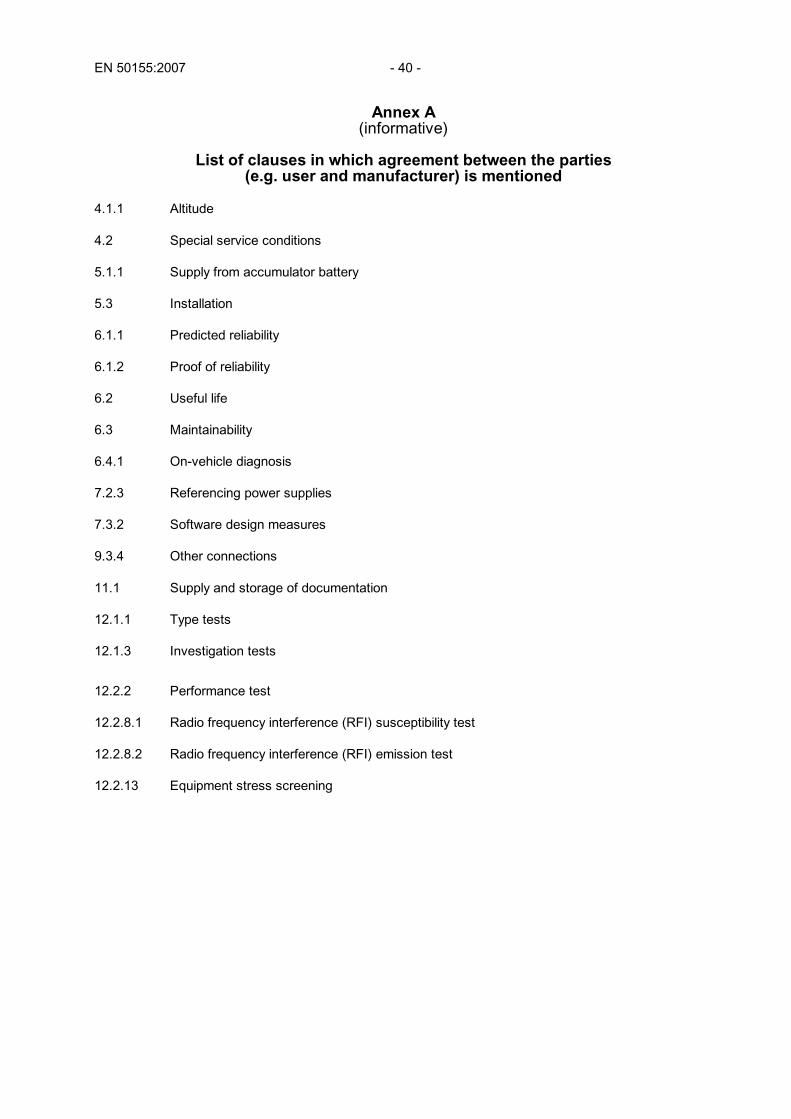
EN 50155:2007 - 40 -
Annex A (informative)
List of clauses in which agreement between the parties
(e.g. user and manufacturer) is mentioned 4.1.1 Altitude 4.2 Special service conditions 5.1.1 Supply from accumulator battery 5.3 Installation 6.1.1 Predicted reliability 6.1.2 Proof of reliability 6.2 Useful life 6.3 Maintainability 6.4.1 On-vehicle diagnosis 7.2.3 Referencing power supplies 7.3.2 Software design measures 9.3.4 Other connections 11.1 Supply and storage of documentation 12.1.1 Type tests 12.1.3 Investigation tests
12.2.2 Performance test 12.2.8.1 Radio frequency interference (RFI) susceptibility test 12.2.8.2 Radio frequency interference (RFI) emission test 12.2.13 Equipment stress screening

- 41 - EN 50155:2007
Bibliography
EN 50121-3-1 2000 Railway Applications - Electromagnetic compatibility Part 3-1: Rolling stock – Train and complete vehicle EN 50125-1 1999 Railway Applications - Environmental conditions for equipment Part 1: Equipment on board rolling stock EN 50129 2003 Railway applications - Communication, signalling and processing systems -
Safety related electronic systems for signalling EN 55016 Series Specification for radio disturbance and immunity measuring apparatus and
methods (CISPR 16 series)

EN 50155:2007 - 42 -
Annex ZZ (informative)
Coverage of Essential Requirements of EC Directives
This European Standard has been prepared under a mandate given to CENELEC by the European Commission and the European Free Trade Association and within its scope the standard covers the following essential requirements out of those given in Annex III of the EC Directives 96/48/EC and 2001/16/EC:
– ER 1.1.1, 1.1.3, 1.1.5, 1.2, 1.3.1 and 1.4.3, related to the system
– ER 2.3.1 and 2.3.2 related to the control-command and signalling subsystem
– ER 2.4.1, 2.4.2 and 2.4.3 related to the rolling stock subsystem. Compliance with this standard provides one means of conformity with the specified essential requirements of the Directives concerned. WARNING: Other requirements and other EC Directives may be applicable to the products falling within the scope of this standard.

blank

BS EN 50155:2007
BSI389 Chiswick High RoadLondonW4 4AL
BSI — British Standards InstitutionBSI is the independent national body responsible for preparing British Standards. It presents the UK view on standards in Europe and at the international level. It is incorporated by Royal Charter.
Revisions
British Standards are updated by amendment or revision. Users of British Standards should make sure that they possess the latest amendments or editions.
It is the constant aim of BSI to improve the quality of our products and services. We would be grateful if anyone finding an inaccuracy or ambiguity while using this British Standard would inform the Secretary of the technical committee responsible, the identity of which can be found on the inside front cover. Tel: +44 (0)20 8996 9000. Fax: +44 (0)20 8996 7400.
BSI offers members an individual updating service called PLUS which ensures that subscribers automatically receive the latest editions of standards.
Buying standards
Orders for all BSI, international and foreign standards publications should be addressed to Customer Services. Tel: +44 (0)20 8996 9001. Fax: +44 (0)20 8996 7001. Email: [email protected]. Standards are also available from the BSI website at http://www.bsi-global.com.
In response to orders for international standards, it is BSI policy to supply the BSI implementation of those that have been published as British Standards, unless otherwise requested.
Information on standards
BSI provides a wide range of information on national, European and international standards through its Library and its Technical Help to Exporters Service. Various BSI electronic information services are also available which give details on all its products and services. Contact the Information Centre. Tel: +44 (0)20 8996 7111. Fax: +44 (0)20 8996 7048. Email: [email protected].
Subscribing members of BSI are kept up to date with standards developments and receive substantial discounts on the purchase price of standards. For details of these and other benefits contact Membership Administration. Tel: +44 (0)20 8996 7002. Fax: +44 (0)20 8996 7001. Email: [email protected].
Information regarding online access to British Standards via British Standards Online can be found at http://www.bsi-global.com/bsonline.
Further information about BSI is available on the BSI website at http://www.bsi-global.com.
Copyright
Copyright subsists in all BSI publications. BSI also holds the copyright, in the UK, of the publications of the international standardization bodies. Except as permitted under the Copyright, Designs and Patents Act 1988 no extract may be reproduced, stored in a retrieval system or transmitted in any form or by any means – electronic, photocopying, recording or otherwise – without prior written permission from BSI.
This does not preclude the free use, in the course of implementing the standard, of necessary details such as symbols, and size, type or grade designations. If these details are to be used for any other purpose than implementation then the prior written permission of BSI must be obtained.
Details and advice can be obtained from the Copyright & Licensing Manager. Tel: +44 (0)20 8996 7070. Fax: +44 (0)20 8996 7553. Email: [email protected].