railect the solution for volumetric assessment of ... · although radiographic inspection is...
TRANSCRIPT
Copyright © RAILECT Consortium 2012
18th World Conference of Non-destructive Testing, 16-20 April 2012, Durban, South Africa
RAILECT The Solution for Volumetric Assessment of Aluminothermic Rail Welds
Angélique Raude1, Tamara Colombier1, John Rudlin1, Elena Jasiuniene2, George Kotsikos3
1 TWI, Cambridge; United Kingdom
Phone: +44 1223 89900, Fax: +44 1223 890 952, e-mail: [email protected], [email protected], [email protected]
2 Kaunas University, Kaunas, Lithuania; e-mail: [email protected] 3 Newrail, United Kingdom; e-mail: [email protected]
Abstract There are millions of aluminothermic welds made each year to join rail in Europe’s rail network and millions are already in-service. Occasionally flaws develop during and shortly after welding and this can lead to early failure therefore causing disruption to train services and costs to both the train operating companies and the maintenance operators. Although radiographic inspection is sometimes carried out, this is not very common, and the conventional ultrasonic standard requires many probes and scans because of the complex geometry of the rail profile. Since the welds are made by a casting process, these can be more difficult to inspect than joints made by other welding processes. Hence, the RAILECT project was conceived to provide a convenient means of inspecting the joints using a multiple phased array ultrasonic system. This article describes the type of flaws concerned, the modelling of the ultrasonics, the practical realisation of a prototype system and the development of acceptance criteria. Keywords: Phased Array Ultrasonic Testing (PAUT), Aluminothermic Welds, Rail, NDT, Inspection. 1 Introduction The majority of field welding in the railway industry is carried out using the aluminothermic technique. Such welds are primarily associated with replacement of rail or weld defects, installation of insulated rail joint and track construction activities. In the UK, it is estimated that Network Rail produces over 65,000 Thermite welds per year and they have approximately 1.5 million welds installed on track. Thermite welding is an effective, highly mobile and cost effective casting method of joining heavy steel structures such as rail; however this is also a very skilled welding process which requires experience and expertise. The many process steps can be altered by the welder and/or the environmental conditions and can therefore result in poorer weld performance and in creation of defects within the weld. Up until this date; only a few techniques of inspection have had some limited success to control the quality of these welds. For instance; manual ultrasonic and radiography techniques are sometimes carried out on the welds but this is not commonly used in the railway industry. Most of the time, only visual inspection is performed. Every new weld is inspected using visual techniques for weld defects, profile and geometry. Although there is no requirement to inspect rail welds using ultrasonic, MPI or DPI techniques, there is a conventional ultrasonic standard EN 14730-1:2006 Annex C [1] developed specifically for the inspection of rail welds. This standard describes a relatively long and complex inspection. It involves the use of

many conventional ultrasonic probes and the complex weld profile geometryAs the welds use a casting process, these can be more difficult to inspect than joints made by other welding processes and as a result visual inspection is currently the only technique regularly used to inspect aluminothermic rail weldsinvolves the removal of potentially non Rail flaw detection has an important part to play in ensuring the safety of railroads. Recent accidents such as the Hatfield disaster in the UK in 2000 caused by broken rail have focused attention on the technologies that enable the detection of flaws in rails and rail welds. The RAILECT project was a European funded develop a novel automated phased array aluminothermic rail welds. The project four SMEs originated from three different European countriesbeing carried out beyond the original scope of the project in order to provide quickly a commercial and marketable solution to the industry within the next few months. 2 Concept 2.1 Rail profiles and weld dimensions The project intention was to focusCEN 60E2 and CEN 56E1 (see Figure European standards and are commonly used within Europe. CEN 60E1 and CEN 60E2 are the most recent profiles whereas CEN 56E1 is an older version. New welds follow the most recent profiles but many welds alwas to create a versatile prototype adapted for the quality control of both new and already in service aluminothermic rail welds.
a. CEN60E1 Figure 1. Dimension of the three different rail profiles currently in use.
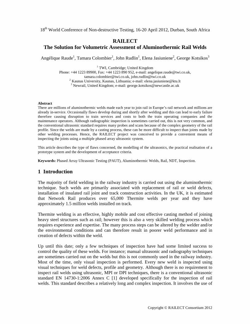
However, due to the timeframe allocated to the project the consortium decided to concentrate on the most recent rail profile (CEN35 mm (see Figure 2), although the finished cast range can vary from 35 The first iteration of the RAILECT prototype was developed for the CENalso fitted the CEN 60E2.
ultrasonic probes and the deployment of time consuming scans because of geometry, making this technique only used occasionally
As the welds use a casting process, these can be more difficult to inspect than joints made by other welding processes and as a result visual inspection is currently the only technique
rly used to inspect aluminothermic rail welds; which is often not reliable enough and the removal of potentially non-critical aluminothermic welds.
Rail flaw detection has an important part to play in ensuring the safety of railroads. Recent dents such as the Hatfield disaster in the UK in 2000 caused by broken rail have focused
attention on the technologies that enable the detection of flaws in rails and rail welds. The a European funded (FP7-SME-2007-1-222425) project which aimed to
develop a novel automated phased array ultrasonic system for the inspection rail welds. The project lasted 2 years and involved three research centres
four SMEs originated from three different European countries. Additional work is currently being carried out beyond the original scope of the project in order to provide quickly a commercial and marketable solution to the industry within the next few months.
2.1 Rail profiles and weld dimensions
focus on three different types of rail profiles CEN 60E1, Figure 1). These three rail profiles are in accordance with the
European standards and are commonly used within Europe. CEN 60E1 and CEN 60E2 are the most recent profiles whereas CEN 56E1 is an older version. New welds follow the most recent profiles but many welds already in service are more likely to be CEN 56E1. The idea was to create a versatile prototype adapted for the quality control of both new and already in service aluminothermic rail welds.
b. CEN60E2 c. CEN 56E1Dimension of the three different rail profiles currently in use.
However, due to the timeframe allocated to the project the consortium decided to concentrate on the most recent rail profile (CEN 60E1). The weld width of concern for the project was
), although the finished cast range can vary from 35 mm to 90 mm.
he first iteration of the RAILECT prototype was developed for the CEN 60E1 rai
scans because of occasionally.
As the welds use a casting process, these can be more difficult to inspect than joints made by other welding processes and as a result visual inspection is currently the only technique
hich is often not reliable enough and
Rail flaw detection has an important part to play in ensuring the safety of railroads. Recent dents such as the Hatfield disaster in the UK in 2000 caused by broken rail have focused
attention on the technologies that enable the detection of flaws in rails and rail welds. The project which aimed to
inspection of research centres and
Additional work is currently being carried out beyond the original scope of the project in order to provide quickly a
three different types of rail profiles CEN 60E1, hese three rail profiles are in accordance with the
European standards and are commonly used within Europe. CEN 60E1 and CEN 60E2 are the most recent profiles whereas CEN 56E1 is an older version. New welds follow the most
ready in service are more likely to be CEN 56E1. The idea was to create a versatile prototype adapted for the quality control of both new and already in
c. CEN 56E1
However, due to the timeframe allocated to the project the consortium decided to concentrate The weld width of concern for the project was
mm to 90 mm.
60E1 rail profile, it
Copyright © RAILECT Consortium 2012
Figure 2. A 35 mm wide aluminothermic rail weld in service.
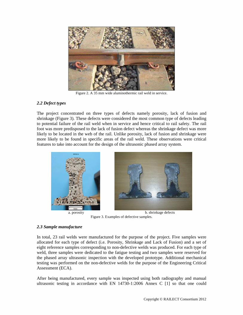
2.2 Defect types The project concentrated on three types of defects namely porosity, lack of fusion and shrinkage (Figure 3). These defects were considered the most common type of defects leading to potential failure of the rail weld when in service and hence critical to rail safety. The rail foot was more predisposed to the lack of fusion defect whereas the shrinkage defect was more likely to be located in the web of the rail. Unlike porosity, lack of fusion and shrinkage were more likely to be found in specific areas of the rail weld. These observations were critical features to take into account for the design of the ultrasonic phased array system.
a. porosity b. shrinkage defects
Figure 3. Examples of defective samples. 2.3 Sample manufacture In total, 23 rail welds were manufactured for the purpose of the project. Five samples were allocated for each type of defect (i.e. Porosity, Shrinkage and Lack of Fusion) and a set of eight reference samples corresponding to non-defective welds was produced. For each type of weld, three samples were dedicated to the fatigue testing and two samples were reserved for the phased array ultrasonic inspection with the developed prototype. Additional mechanical testing was performed on the non-defective welds for the purpose of the Engineering Critical Assessment (ECA). After being manufactured, every sample was inspected using both radiography and manual ultrasonic testing in accordance with EN 14730-1:2006 Annex C [1] so that one could
Copyright © RAILECT Consortium 2012
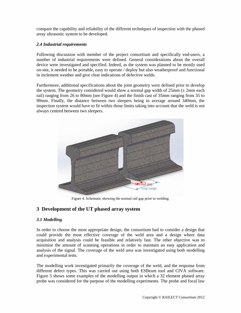
compare the capability and reliability of the different techniques of inspection with the phased array ultrasonic system to be developed. 2.4 Industrial requirements Following discussion with member of the project consortium and specifically end-users, a number of industrial requirements were defined. General considerations about the overall device were investigated and specified. Indeed, as the system was planned to be mostly used on-site, it needed to be portable, easy to operate / deploy but also weatherproof and functional in inclement weather and give clear indications of defective welds. Furthermore, additional specifications about the joint geometry were defined prior to develop the system. The geometry considered would show a normal gap width of 25mm (± 2mm each rail) ranging from 26 to 80mm (see Figure 4) and the finish cast of 35mm ranging from 35 to 90mm. Finally, the distance between two sleepers being in average around 340mm, the inspection system would have to fit within those limits taking into account that the weld is not always centred between two sleepers.
Figure 4. Schematic showing the normal rail gap prior to welding.
3 Development of the UT phased array system 3.1 Modelling In order to choose the most appropriate design, the consortium had to consider a design that could provide the most effective coverage of the weld area and a design where data acquisition and analysis could be feasible and relatively fast. The other objective was to minimise the amount of scanning operations in order to maintain an easy application and analysis of the signal. The coverage of the weld area was investigated using both modelling and experimental tests. The modelling work investigated primarily the coverage of the weld, and the response from different defect types. This was carried out using both ESBeam tool and CIVA software. Figure 5 shows some examples of the modelling output in which a 32 element phased array probe was considered for the purpose of the modelling experiments. The probe and focal law
Normal gap Gap range
Copyright © RAILECT Consortium 2012
parameters were varied during the modelling experiments so that the most appropriate settings for full volumetric weld coverage could be identified.
Figure 5. Modelling experiments using Civa software showing beam coverage.
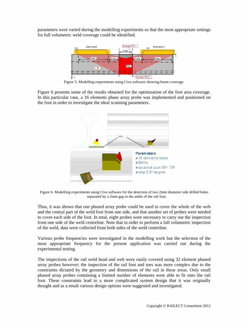
Figure 6 presents some of the results obtained for the optimisation of the foot area coverage. In this particular case, a 16 elements phase array probe was implemented and positioned on the foot in order to investigate the ideal scanning parameters.
Figure 6. Modelling experiments using Civa software for the detection of two 2mm diameter side drilled holes
separated by a 2mm gap in the ankle of the rail foot. Thus, it was shown that one phased array probe could be used to cover the whole of the web and the central part of the weld foot from one side, and that another set of probes were needed to cover each side of the foot. In total, eight probes were necessary to carry out the inspection from one side of the weld centreline. Note that in order to perform a full volumetric inspection of the weld, data were collected from both sides of the weld centreline. Various probe frequencies were investigated in the modelling work but the selection of the most appropriate frequency for the present application was carried out during the experimental testing. The inspections of the rail weld head and web were easily covered using 32 element phased array probes however; the inspection of the rail foot and toes was more complex due to the constraints dictated by the geometry and dimensions of the rail in these areas. Only small phased array probes containing a limited number of elements were able to fit onto the rail foot. These constraints lead to a more complicated system design that it was originally thought and as a result various design options were suggested and investigated.
Copyright © RAILECT Consortium 2012
3.2 System and Prototype design For the purpose of data acquisition and analysis, commercially available phased array instrument and software were used jointly to carry out the inspection and the recording of the data. The focal laws were developed during the laboratory trials and optimised prior to being set up and saved in the instrument. Initially each law would be loaded and used at a time but their application could be controlled to enable an automatic sequencing to facilitate an automated inspection of the joint. The data output were collected for analysis and compared with the acceptance criteria by means of a MATLAB routine specifically developed for this application. In order to deploy the PAUT probes correctly around the rail joint, a specific prototype design was developed based on the modelling and laboratory trials. This system was clamped to the side of the railhead and combined all the PAUT probes necessary for a volumetric inspection. Those were then held in place around the rail profile by means of clamping mechanisms. 4 Acceptance criteria 4.1 Mechanical tests The majority of the mechanical testing was performed for the purpose of the Engineering Critical Assessment (ECA) calculations. The following tests were carried out:
• Hardness testing - SS EN 14730-1:2006 • Tensile testing - BS EN 10002-1: 2001 • Fracture toughness testing - BS 7448-1:1g91 • Fatigue testing - BS EN 14730-1:2006
Results for the fatigue testing showed that generally non defective welds failed in the Heat Affected Zone (HAZ) whereas defective welds failed within the weld, as expected, stresses being introduced by the defects. 4.2 Engineering Critical Assessment results ECA calculations were carried out for different areas of the rail weld in accordance with procedures specified in BS 7910:2005. Both surface breaking flaws and internal flaws were assessed. Sensitivity analysis was carried out to determine some critical conditions such as flaw geometry and relative distance to surface for internal flaws. A Finite Element Analysis (FEA) model was also created to assess the accuracy of the analytical solutions developed with the ECA calculations. The model was based on the parameters provided by fatigue test activities. Example of the modelling work is shown in Figure 7.

Figure 7. Finite element modelling built from the results of the mechanical testing. 5 Prototype trials 5.1 Laboratory trials Laboratory trials were carried out to verify the correct operation of the focal laws and the detection of defects. Some of the results are shown in the Figure 8 shows the validation of the model described in Figure 6 related to the inspection of the rail foot. The two 2mm diameter law parameters given by the model.though they were only distant by 2mm.
Figure 8. Sectorial scan performed on the ankle of the rail foot containing two 2mm side drilled holes in the rail
Figure 9 shows the scan obtained for the inspection of the web of the railthe scan is obtained by the probe located on top of the rail at a selected probe offset with regards to the rail weld centreline. Both non defective and defective welds are illustrated on the figure below. One might notice that the bottom of the rail weld due to the irregular surface finish underneath the rail foot. Ta reference position when carrying out the inspection.
Finite element modelling built from the results of the mechanical testing.
Laboratory trials were carried out to verify the correct operation of the focal laws and the of the results are shown in the Figure 8 and Figure 9.
Figure 8 shows the validation of the model described in Figure 6 related to the inspection of 2mm diameter side drilled holes were detected using the probe and focal
law parameters given by the model. Moreover, it was also possible to distinguish them even though they were only distant by 2mm.
Sectorial scan performed on the ankle of the rail foot containing two 2mm side drilled holes in the rail
foot.
shows the scan obtained for the inspection of the web of the rail weldby the probe located on top of the rail at a selected probe offset with
he rail weld centreline. Both non defective and defective welds are illustrated on the figure below. One might notice that the bottom of the rail weld was easily seen on the scandue to the irregular surface finish underneath the rail foot. These indications could be used as a reference position when carrying out the inspection.
Finite element modelling built from the results of the mechanical testing.
Laboratory trials were carried out to verify the correct operation of the focal laws and the
Figure 8 shows the validation of the model described in Figure 6 related to the inspection of side drilled holes were detected using the probe and focal
o distinguish them even
Sectorial scan performed on the ankle of the rail foot containing two 2mm side drilled holes in the rail
weld. In this case, by the probe located on top of the rail at a selected probe offset with
he rail weld centreline. Both non defective and defective welds are illustrated on easily seen on the scan
could be used as
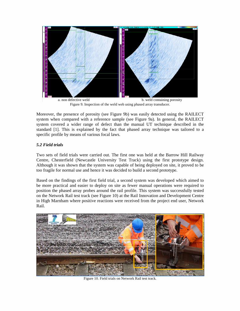
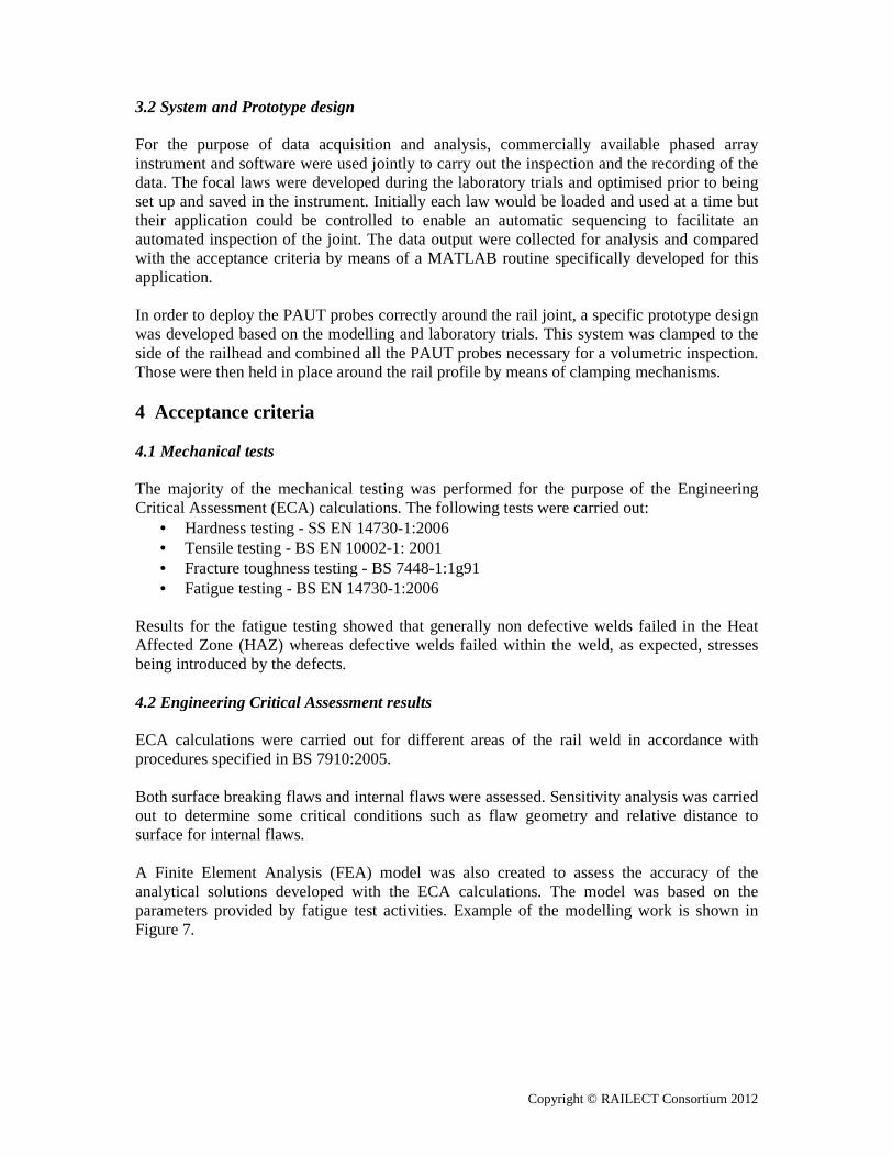
Figure 9. Inspection of the weld web using phased array transducer.
Moreover, the presence of porosity (see Figure 9b) was easily detected using the RAILECT system when compared with a reference sample (see Figure 9a). In general, the RAILECT system covered a wider range of defect than the manual UT technique described in the standard [1]. This is explained by the fact that phased array technique was tailored to a specific profile by means of various focal laws. 5.2 Field trials Two sets of field trials were carried out. The first one was held at the Barrow Hill Railway Centre, Chesterfield (Newcastle University Test Track) using the first prototype design. Although it was shown that the system was capable of being deployed on site, it proved to be too fragile for normal use and hence it was decided to build a second prototype. Based on the findings of the first field trial, a second system was developed which aimed to be more practical and easier to deploy on site as fewer manual operations were required to position the phased array probes around the rail profile. This system was successfully tested on the Network Rail test track (see Figure 10) at the Rail Innovation and Development Centre in High Marnham where positive reactions were received from the project end user, Network Rail.
Figure 10. Field trials on Network Rail test track.
a. non defective weld b. weld containing porosity
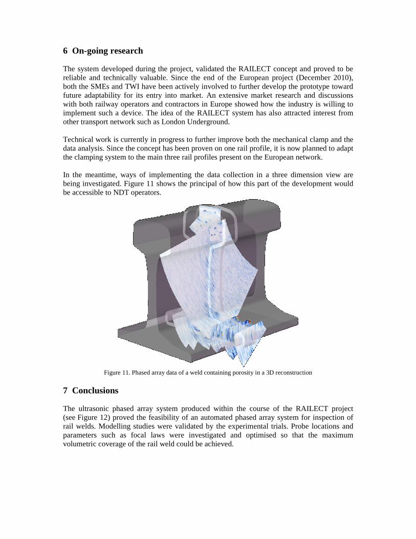
6 On-going research The system developed during the project, validated the RAILECT concept and proved to be reliable and technically valuable. both the SMEs and TWI have been future adaptability for its entry with both railway operators and contractors in Europe showed how the industry is willing to implement such a device. The idea of the RAILECT system has other transport network such as London Underground Technical work is currently in progress to data analysis. Since the concept has been proven on one rail profile, it is now pthe clamping system to the main three rail profile In the meantime, ways of implementing the data collection in a three dimension view are being investigated. Figure 11 shows the principal of how this part of the development would be accessible to NDT operators.
Figure 11. Phased array data of a weld containing porosity in a 3D reconstructio 7 Conclusions The ultrasonic phased array system produced within the course of the RAILECT project(see Figure 12) proved the feasibility of an automated phased array system for inspection of rail welds. Modelling studies were validated by the experimental trials. Probe locations and parameters such as focal laws were investigated and optimised so that the maximum volumetric coverage of the rail weld could be achieved.
The system developed during the project, validated the RAILECT concept and proved to be reliable and technically valuable. Since the end of the European project (December 2010)
have been actively involved to further develop the protofuture adaptability for its entry into market. An extensive market research and discussions with both railway operators and contractors in Europe showed how the industry is willing to
The idea of the RAILECT system has also attracted interest from London Underground.
is currently in progress to further improve both the mechanical clamp and the data analysis. Since the concept has been proven on one rail profile, it is now planned to adapt the clamping system to the main three rail profiles present on the European network.
In the meantime, ways of implementing the data collection in a three dimension view are shows the principal of how this part of the development would
Phased array data of a weld containing porosity in a 3D reconstruction
The ultrasonic phased array system produced within the course of the RAILECT projectproved the feasibility of an automated phased array system for inspection of
rail welds. Modelling studies were validated by the experimental trials. Probe locations and ocal laws were investigated and optimised so that the maximum
volumetric coverage of the rail weld could be achieved.
The system developed during the project, validated the RAILECT concept and proved to be (December 2010),
to further develop the prototype toward An extensive market research and discussions
with both railway operators and contractors in Europe showed how the industry is willing to also attracted interest from
both the mechanical clamp and the lanned to adapt
present on the European network.
In the meantime, ways of implementing the data collection in a three dimension view are shows the principal of how this part of the development would
n
The ultrasonic phased array system produced within the course of the RAILECT project proved the feasibility of an automated phased array system for inspection of
rail welds. Modelling studies were validated by the experimental trials. Probe locations and ocal laws were investigated and optimised so that the maximum
Copyright © RAILECT Consortium 2012
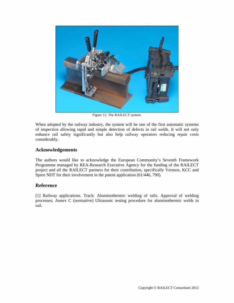
Figure 12. The RAILECT system.
When adopted by the railway industry, the system will be one of the first automatic systems of inspection allowing rapid and simple detection of defects in rail welds. It will not only enhance rail safety significantly but also help railway operators reducing repair costs considerably. Acknowledgements The authors would like to acknowledge the European Community’s Seventh Framework Programme managed by REA-Research Executive Agency for the funding of the RAILECT project and all the RAILECT partners for their contribution, specifically Vermon, KCC and Spree NDT for their involvement in the patent application (61/446, 790). Reference [1] Railway applications. Track: Aluminothermic welding of rails. Approval of welding processes; Annex C (normative) Ultrasonic testing procedure for aluminothermic welds in rail.