rail-free solar mounting system for composite and tile
TRANSCRIPT
LightSpeed Mount Rail-free Solar Mounting System for Composite and Tile Roofs
Installation Manual
5004849
Pegasus Solar Inc. | 100 West Ohio Ave., Richmond, CA 94804 | 408.638.9655
www.pegasussolar.com

INSTALLATION MANUAL
©2017 Pegasus Solar Inc. | Pegasus Solar reserves the right to make specification changeswithout any prior written notice. All rights reserved. Doc #: 917-0001-001 Rev A
2
Table of ContentsOverview . . . . . . . . . . . . . . . . . . . . . . . . . . . . . . . . . . . . . . . . . . . . . . . . . . . . . . . . . . . . . . . . . . . . . . . . . . . . . . . . . . . 3
Ratings . . . . . . . . . . . . . . . . . . . . . . . . . . . . . . . . . . . . . . . . . . . . . . . . . . . . . . . . . . . . . . . . . . . . . . . . . . . . . . . . . . . . . 3
Certifications and Code Compliance . . . . . . . . . . . . . . . . . . . . . . . . . . . . . . . . . . . . . . . . . . . . . . . . . . . . . . . . . . . 3
Safety . . . . . . . . . . . . . . . . . . . . . . . . . . . . . . . . . . . . . . . . . . . . . . . . . . . . . . . . . . . . . . . . . . . . . . . . . . . . . . . . . . . . . . 3
Parts List . . . . . . . . . . . . . . . . . . . . . . . . . . . . . . . . . . . . . . . . . . . . . . . . . . . . . . . . . . . . . . . . . . . . . . . . . . . . . . . . . . . 4
Product Identification . . . . . . . . . . . . . . . . . . . . . . . . . . . . . . . . . . . . . . . . . . . . . . . . . . . . . . . . . . . . . . . . . . . . . . . . 5
Mount Assembly Diagram . . . . . . . . . . . . . . . . . . . . . . . . . . . . . . . . . . . . . . . . . . . . . . . . . . . . . . . . . . . . . . . . . . . . 6
Step One –Design Array Layout on Roof . . . . . . . . . . . . . . . . . . . . . . . . . . . . . . . . . . . . . . . . . . . . . . . . . . . . . . . 7
Step Two – Mark Rafters and Determine Attachment Points . . . . . . . . . . . . . . . . . . . . . . . . . . . . . . . . . . . . . . 8
Step Three – Install and Level Mount Assemblies . . . . . . . . . . . . . . . . . . . . . . . . . . . . . . . . . . . . . . . . . . . . . . . . 9
Step Four – Wire Management . . . . . . . . . . . . . . . . . . . . . . . . . . . . . . . . . . . . . . . . . . . . . . . . . . . . . . . . . . . . . .11-12
Step Five – Install Modules . . . . . . . . . . . . . . . . . . . . . . . . . . . . . . . . . . . . . . . . . . . . . . . . . . . . . . . . . . . . . . . . 13-15
Tile Roof Installation Instructions . . . . . . . . . . . . . . . . . . . . . . . . . . . . . . . . . . . . . . . . . . . . . . . . . . . . . . . . . . . 16-19
Double Mount Installation Instructions . . . . . . . . . . . . . . . . . . . . . . . . . . . . . . . . . . . . . . . . . . . . . . . . . . . . . . . . 20
Optional – Skirt Installation Instructions . . . . . . . . . . . . . . . . . . . . . . . . . . . . . . . . . . . . . . . . . . . . . . . . . . . . . . . .21
Removing a Module . . . . . . . . . . . . . . . . . . . . . . . . . . . . . . . . . . . . . . . . . . . . . . . . . . . . . . . . . . . . . . . . . . . . . . . . 22
Bonding Connection Paths to Ground . . . . . . . . . . . . . . . . . . . . . . . . . . . . . . . . . . . . . . . . . . . . . . . . . . . . . . . . 24
Bonding and Grounding the Array . . . . . . . . . . . . . . . . . . . . . . . . . . . . . . . . . . . . . . . . . . . . . . . . . . . . . . . . . . . . 25
Best Practice . . . . . . . . . . . . . . . . . . . . . . . . . . . . . . . . . . . . . . . . . . . . . . . . . . . . . . . . . . . . . . . . . . . . . . . . . . . . . . . 26
Maintenance . . . . . . . . . . . . . . . . . . . . . . . . . . . . . . . . . . . . . . . . . . . . . . . . . . . . . . . . . . . . . . . . . . . . . . . . . . . . . . . 26
Troubleshooting and Removal of System . . . . . . . . . . . . . . . . . . . . . . . . . . . . . . . . . . . . . . . . . . . . . . . . . . . . . . 27
Appendix A – Torque and Pull-Out Specs . . . . . . . . . . . . . . . . . . . . . . . . . . . . . . . . . . . . . . . . . . . . . . . . . . . . . 28
Torque Settings for LightSpeed Mount hardware . . . . . . . . . . . . . . . . . . . . . . . . . . . . . . . . . . 28
Lag pull-out strengths in common lumber (lbs) . . . . . . . . . . . . . . . . . . . . . . . . . . . . . . . . . . . 28
Appendix B – LightSpeed Mount Compatible Modules for UL2703 Electrical Bonding/Grounding . . . 29
Appendix C – Approved Module Load Characteristics . . . . . . . . . . . . . . . . . . . . . . . . . . . . . . . . . . . . . . . . . . 30
Appendix D – Span Tables . . . . . . . . . . . . . . . . . . . . . . . . . . . . . . . . . . . . . . . . . . . . . . . . . . . . . . . . . . . . . . . . 31-50
Pegasus Solar looks forward to receiving your input regarding the accuracy and user friendliness of this publication. Please email [email protected] with your comments.
INSTALLATION MANUAL
©2017 Pegasus Solar Inc. | Pegasus Solar reserves the right to make specification changeswithout any prior written notice. All rights reserved. Doc #: 917-0001-001 Rev A
3
Overview
This Installation Manual covers the required aspects of installing the Pegasus Solar LightSpeed Mount Residential rail-free mounting system. LightSpeed Mount Residential is engineered for residential sloped roofs with wood frame construction. This system is intended for use with solar modules that have the patent pending Pegasus Corner Hinges factory installed. Please contact us for the latest list of modules with LightSpeed Corner Hinges.
The LightSpeed Mount may be used to ground and/or mount a PV module complying with UL 1703 only when the specific module has been evaluated for grounding and/or mounting in compliance with the included instructions. Periodic inspection of the mounting system should be conducted for loose components, loose fasteners, or any corrosion, and if found, those components should be replaced immediately. Keep copper away from aluminum and galvanized steel by securing bare copper conductors in a fashion that maintains a minimum 1/4” separation.
Certifications and Code Compliance
• UL 2703 for Electrical Bonding and Grounding.
• UL 2703 Fire Class A for steep-slope roofs when using Type 1 and Type 2 listed PV modules (Skirt optional).
• UL 2703 Fire Class A for low-slope roofs when using Skirt with 2 1/8” or less gap between roof and Skirt, and when using Type 1 and Type 2 listed PV modules.
• ASCE 7-05 Minimum Design Loads for Buildings and Other Structures.
• ASCE 7-10 Minimum Design Loads for Buildings Other Structures.
Safety
• Wear proper OSHA approved safety equipment when working on a roof.
• Wear proper eye and fall protection.
• Use properly anchored fall protection equipment. LightSpeed Mount products are not rated as fall protection equipment and should not be used as such.
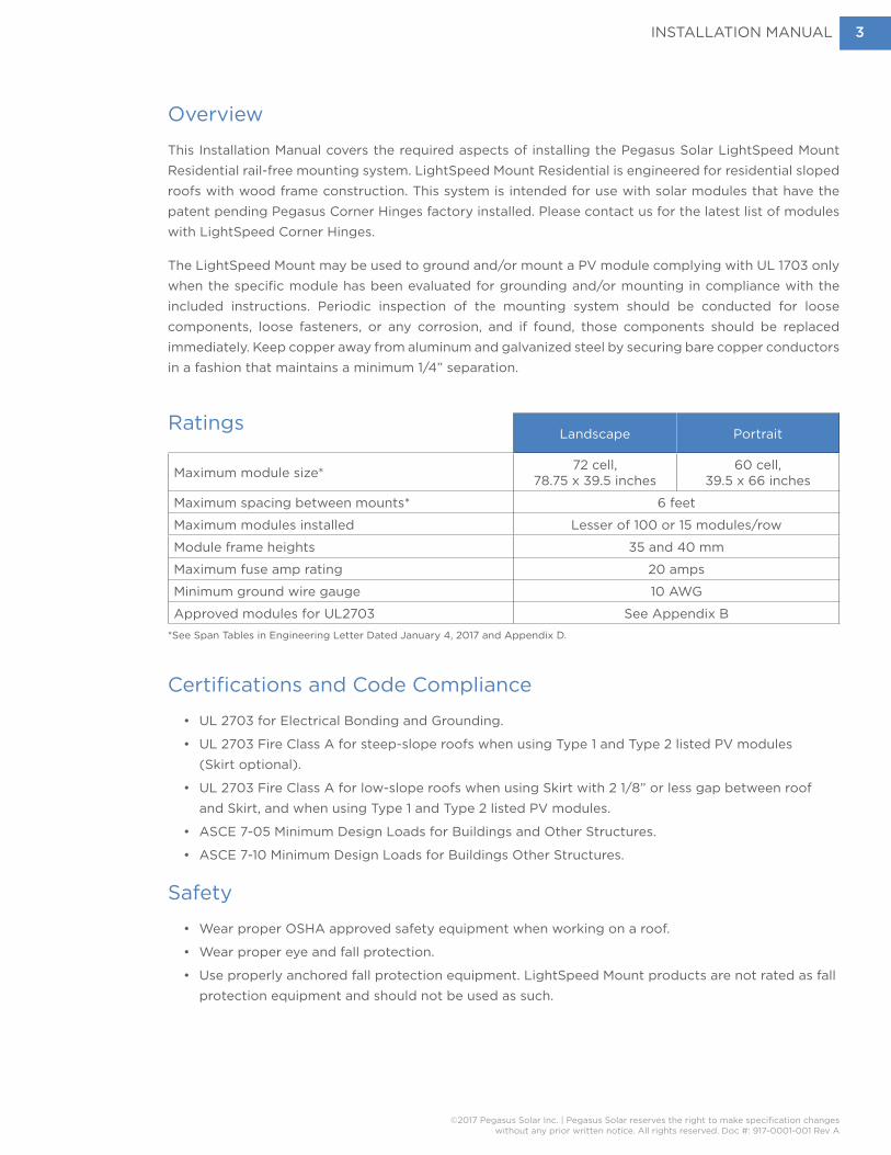
Ratings Landscape Portrait
Maximum module size* 72 cell, 78.75 x 39.5 inches
60 cell, 39.5 x 66 inches
Maximum spacing between mounts* 6 feet
Maximum modules installed Lesser of 100 or 15 modules/row
Module frame heights 35 and 40 mm
Maximum fuse amp rating 20 amps
Minimum ground wire gauge 10 AWG
Approved modules for UL2703 See Appendix B*See Span Tables in Engineering Letter Dated January 4, 2017 and Appendix D.

INSTALLATION MANUAL
©2017 Pegasus Solar Inc. | Pegasus Solar reserves the right to make specification changeswithout any prior written notice. All rights reserved. Doc #: 917-0001-001 Rev A
4
Tools Required• Socket Wrench
• Tape measure• Chalk• Chalk line• String line• Roofing flat bar• Drill, Impact Drill• 1/2-inch-deep socket with
drill adaptor• 7/32-inch jobber bit• Caulking gun with proper
roofing sealant• 1/4” Drive click torque wrench
with 20-200 inch-pound capability
Parts List
Mounting Assembly
Single MountUL 2703 Tested & Certified
Tighten to 135 in-lbs
LightSpeed FlashingAC 286 Rain Tested with and
without sealant
5/16-inch 18-8 Stainless Steel Lag Screw
(Select length for minimum 2 1/2-inch depth into rafter)
Double MountUL 2703 Tested & Certified
Tighten to 135 in-lbs

INSTALLATION MANUAL
©2017 Pegasus Solar Inc. | Pegasus Solar reserves the right to make specification changeswithout any prior written notice. All rights reserved. Doc #: 917-0001-001 Rev A
5
Bonding
Optional Parts
WEEB-LUG-8.0UL 467 and UL 2703 Tested &
Certified (WEEB Washers are not required with this system)
Product Identification
System identification can be made by looking the Single Mount, which has a label showing the ETL mark with the following information:
• Manufacturer name, trademark, and/or logo
• Model Name
• Date of manufacture not exceeding any three consecutive months
Skirt Bonding StrapIlsco SBJ-516-X (“X” is length)
UL 2703 Tested & Certified.
Hex Serrated Flange Bolt18-8 SS – 5/16-18 x 2-1/2”
with 1/2” hex head
Solar Module
Solar Module with LightSpeed Corners (See Appendix B for list of compatible modules)LightSpeed Corners UL 2703 Tested & Certified
5/16-18 x 1 1/2-inch Stainless Steel Serrated Flange BoltUL 2703 Tested & Certified
Tighten to 170 in-lbs
Array SkirtRoof pitch >2:12: Not required
Roof pitch < 2:12: Required UL 1703 Fire and UL 2703 Tested
& Certified Class A
INSTALLATION MANUAL
©2017 Pegasus Solar Inc. | Pegasus Solar reserves the right to make specification changeswithout any prior written notice. All rights reserved. Doc #: 917-0001-001 Rev A
6
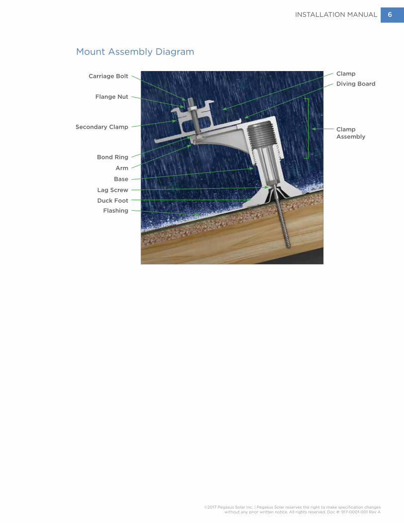
Mount Assembly Diagram
Carriage Bolt Clamp
Diving Board
Clamp Assembly
Flange Nut
Bond Ring
Arm
Base
Lag Screw
FlashingDuck Foot
Secondary Clamp
INSTALLATION MANUAL
©2017 Pegasus Solar Inc. | Pegasus Solar reserves the right to make specification changeswithout any prior written notice. All rights reserved. Doc #: 917-0001-001 Rev A
7
Design Array Layout on Roof
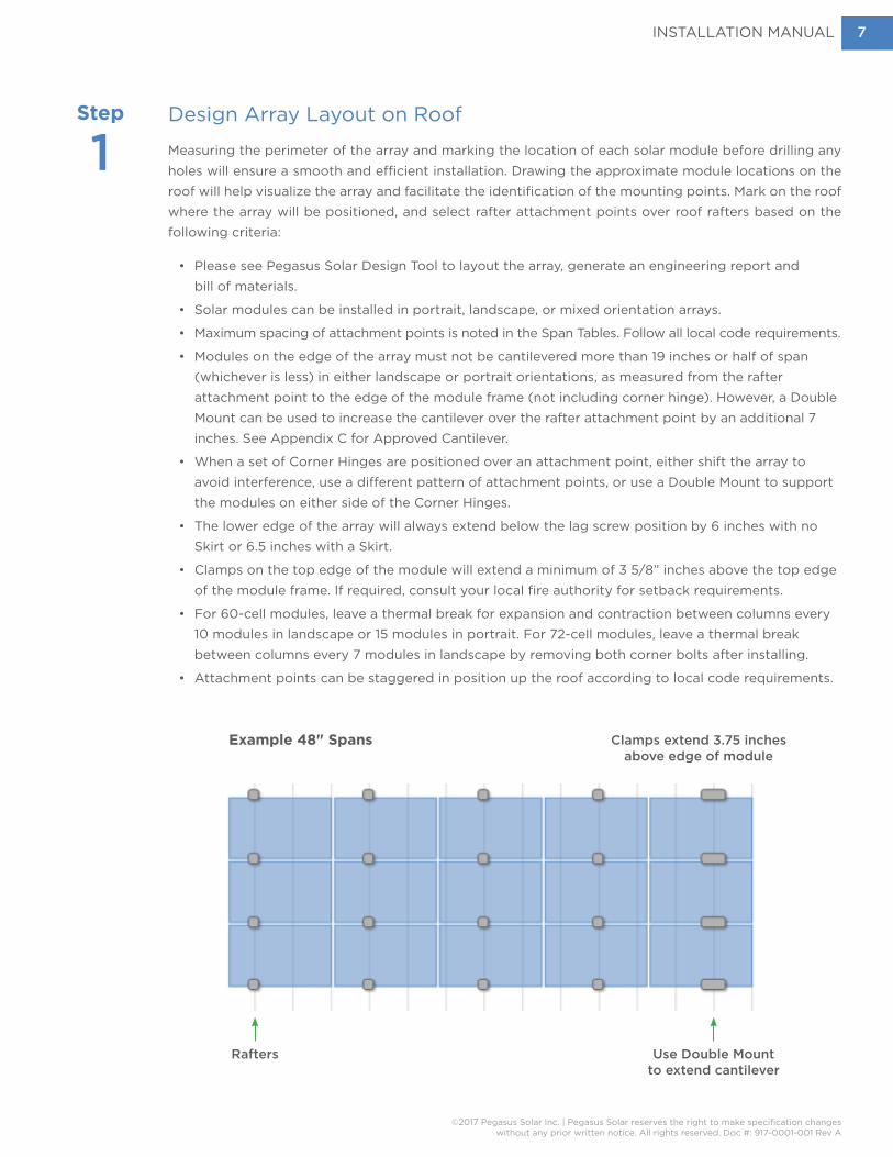
Measuring the perimeter of the array and marking the location of each solar module before drilling any holes will ensure a smooth and efficient installation. Drawing the approximate module locations on the roof will help visualize the array and facilitate the identification of the mounting points. Mark on the roof where the array will be positioned, and select rafter attachment points over roof rafters based on the following criteria:
• Please see Pegasus Solar Design Tool to layout the array, generate an engineering report and bill of materials.
• Solar modules can be installed in portrait, landscape, or mixed orientation arrays.
• Maximum spacing of attachment points is noted in the Span Tables. Follow all local code requirements.
• Modules on the edge of the array must not be cantilevered more than 19 inches or half of span (whichever is less) in either landscape or portrait orientations, as measured from the rafter attachment point to the edge of the module frame (not including corner hinge). However, a Double Mount can be used to increase the cantilever over the rafter attachment point by an additional 7 inches. See Appendix C for Approved Cantilever.
• When a set of Corner Hinges are positioned over an attachment point, either shift the array to avoid interference, use a different pattern of attachment points, or use a Double Mount to support the modules on either side of the Corner Hinges.
• The lower edge of the array will always extend below the lag screw position by 6 inches with no Skirt or 6.5 inches with a Skirt.
• Clamps on the top edge of the module will extend a minimum of 3 5/8” inches above the top edge of the module frame. If required, consult your local fire authority for setback requirements.
• For 60-cell modules, leave a thermal break for expansion and contraction between columns every 10 modules in landscape or 15 modules in portrait. For 72-cell modules, leave a thermal break between columns every 7 modules in landscape by removing both corner bolts after installing.
• Attachment points can be staggered in position up the roof according to local code requirements.
Step
1
Rafters Use Double Mount to extend cantilever
Clamps extend 3.75 inches above edge of module
Example 48" Spans
INSTALLATION MANUAL
©2017 Pegasus Solar Inc. | Pegasus Solar reserves the right to make specification changeswithout any prior written notice. All rights reserved. Doc #: 917-0001-001 Rev A
8
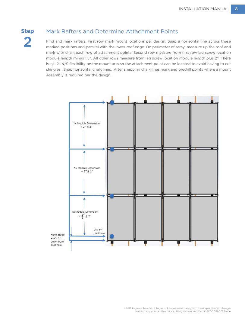
Mark Rafters and Determine Attachment Points
Find and mark rafters. First row mark mount locations per design. Snap a horizontal line across these marked positions and parallel with the lower roof edge. On perimeter of array: measure up the roof and mark with chalk each row of attachment points. Second row measure from first row lag screw location module length minus 1.5”. All other rows measure from lag screw location module length plus 2”. There is +/- 2” N/S flexibility on the mount arm so the attachment point can be located to avoid having to cut shingles. Snap horizontal chalk lines. After snapping chalk lines mark and predrill points where a mount Assembly is required per the design.
Step
2

INSTALLATION MANUAL
©2017 Pegasus Solar Inc. | Pegasus Solar reserves the right to make specification changeswithout any prior written notice. All rights reserved. Doc #: 917-0001-001 Rev A
9
Install and Level Mount Assemblies
Determine hole position based on the acceptable flashing location and per the layout marked in Step Two. Holes can be ±1 1/2 inches from horizontal chalk line to ensure proper location on shingle course. Keeping drill square to the roof, drill a pilot hole 3 inches into roof using a 7/32-inch jobber bit.
Use roofing bar to loosen shingles above attachment point. Slide flashing under shingles and center over hole.
Spin Single Mount onto top of Base a minimum of 4 turns, or 1/2 inch down onto Base. One rotation equals 1/8 inch.
Fill hole with an approved roofing sealant.
Optional: run bead of sealant in U-shape on underside of flashing.
Place Base over flashing cone with the Base Foot facing down the roof. Insert lag screw through Base and use a 1/2-inch-deep socket with a drill to install lag fully. When lag screw is tight, Base should not be able to move or rotate.
Step
3
OPTIONAL
✘
✘
✘
✔
✔
✔
✔
ACCEPTABLE FLASHING LOCATION
Flashing extends under two courses of shingles.
Flashing does NOT extend under two courses of shingles. Flashing should not overhang downslope shingle.
If required, trim shingle to fit around the Base.
INSTALLATION MANUAL
©2017 Pegasus Solar Inc. | Pegasus Solar reserves the right to make specification changeswithout any prior written notice. All rights reserved. Doc #: 917-0001-001 Rev A
10
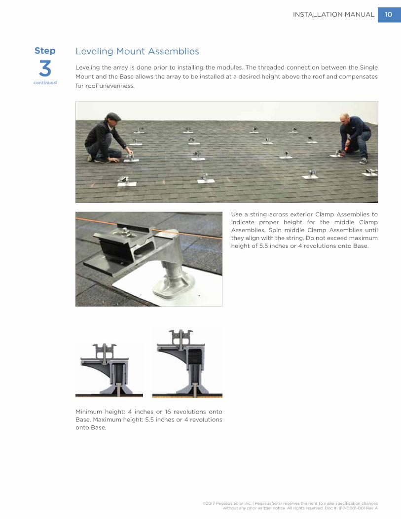
Leveling Mount Assemblies
Leveling the array is done prior to installing the modules. The threaded connection between the Single Mount and the Base allows the array to be installed at a desired height above the roof and compensates for roof unevenness.
Use a string across exterior Clamp Assemblies to indicate proper height for the middle Clamp Assemblies. Spin middle Clamp Assemblies until they align with the string. Do not exceed maximum height of 5.5 inches or 4 revolutions onto Base.
Minimum height: 4 inches or 16 revolutions onto Base. Maximum height: 5.5 inches or 4 revolutions onto Base.
Step
3continued
INSTALLATION MANUAL
©2017 Pegasus Solar Inc. | Pegasus Solar reserves the right to make specification changeswithout any prior written notice. All rights reserved. Doc #: 917-0001-001 Rev A
11
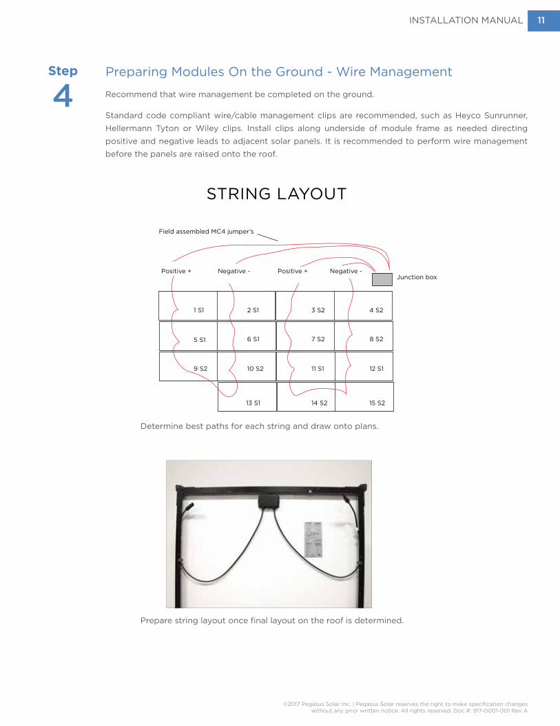
Preparing Modules On the Ground - Wire Management
Recommend that wire management be completed on the ground.
Standard code compliant wire/cable management clips are recommended, such as Heyco Sunrunner, Hellermann Tyton or Wiley clips. Install clips along underside of module frame as needed directing positive and negative leads to adjacent solar panels. It is recommended to perform wire management before the panels are raised onto the roof.
Step
4
Determine best paths for each string and draw onto plans.
Prepare string layout once final layout on the roof is determined.
Positive +Positive + Negative - Negative -
STRING LAYOUT
13 S1 14 S2 15 S2
12 S111 S110 S2
5 S1 6 S1 7 S2
4 S23 S22 S1
9 S2
8 S2
1 S1
Determine best paths for each string and draw onto plans.
Junction box
Field assembled MC4 jumper’s

INSTALLATION MANUAL
©2017 Pegasus Solar Inc. | Pegasus Solar reserves the right to make specification changeswithout any prior written notice. All rights reserved. Doc #: 917-0001-001 Rev A
12
Wire Management with an Solar Edge Optimizer
Install optimizer in top left or right corner depending on module location in string. Tighten to 11 ft bs.
Remove the optimizer provided identification stickers and place them on the array layout. Use a marker and label each module consistent with the string layout to esure proper placement in the array on the roof.
Homeruns should be zip tied together every three feet and attached to the module with wire clips.
Other SolarEdge optimizer models and micro-inverters may require an UL 2703 listed component bracket. Install per manufacturer’s instructions.
Slightly braid the module wires and connect to the optimizer. Secure wires to module frame using stainless steel wire clips such as Heyco Sunrunner, Hellerman Tyton or Wiley. Press wires completely into the clip. Do not coil the wires too tightly and address all wires before installing the modules.
Step
4continued
INSTALLATION MANUAL
©2017 Pegasus Solar Inc. | Pegasus Solar reserves the right to make specification changeswithout any prior written notice. All rights reserved. Doc #: 917-0001-001 Rev A
13
Step
5
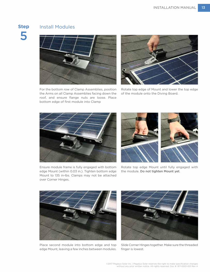
For the bottom row of Clamp Assemblies, position the Arms on all Clamp Assemblies facing down the roof, and ensure flange nuts are loose. Place bottom edge of first module into Clamp
Ensure module frame is fully engaged with bottom edge Mount (within 0.03 in.). Tighten bottom edge Mount to 135 in-lbs. Clamps may not be attached over Corner Hinges.
Place second module into bottom edge and top edge Mount, leaving a few inches between modules.
Slide Corner Hinges together. Make sure the threaded finger is lowest.
Rotate top edge of Mount and lower the top edge of the module onto the Diving Board.
Rotate top edge Mount until fully engaged with the module. Do not tighten Mount yet.
Install Modules
INSTALLATION MANUAL
©2017 Pegasus Solar Inc. | Pegasus Solar reserves the right to make specification changeswithout any prior written notice. All rights reserved. Doc #: 917-0001-001 Rev A
14
Step
5continued
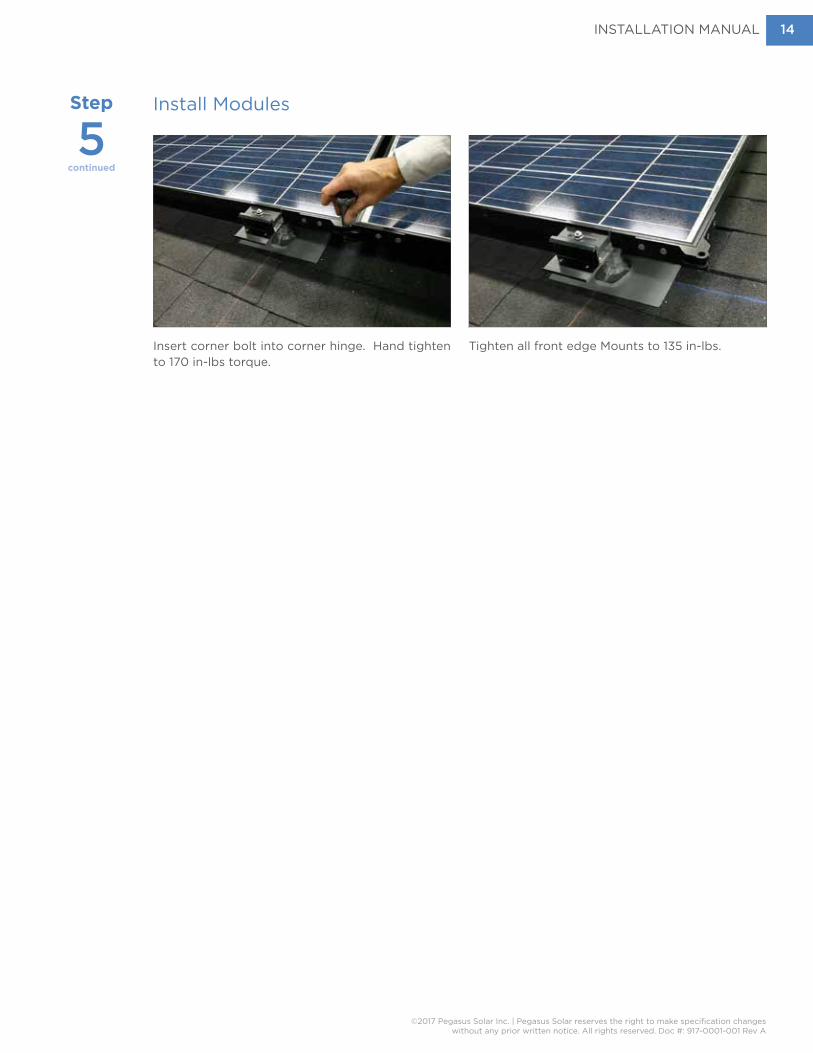
Insert corner bolt into corner hinge. Hand tighten to 170 in-lbs torque.
Tighten all front edge Mounts to 135 in-lbs.
Install Modules

INSTALLATION MANUAL
©2017 Pegasus Solar Inc. | Pegasus Solar reserves the right to make specification changeswithout any prior written notice. All rights reserved. Doc #: 917-0001-001 Rev A
15
Additional Module Rows
For the second and subsequent rows, place bottom edge of module into Clamp. Rotate top edge Mount, and lower the top edge of the module onto the Diving Board. Ensure module frame is fully engaged with bottom edge Mount (within 0.03 inches). Tighten bottom edge Mount to 135 in-lbs. Rotate top edge Mount until fully engaged with the module. Do not tighten top edge Mounts yet.
Place second module on bottom and top edge Clamp Assemblies a few inches to the side of the first module, then slide module into hinges. Working from the side of the module may help in this step.
Insert serrated flange bolts in upper and lower Corner Hinges. Start both bolts, then tighten to 170 in-lbs. Tighten bottom edge Single Mount on second module to 135 in-lbs. Continue this pattern until the second and all subsequent module rows are complete. On the last row of modules, tighten all the top edge Clamp Assemblies as you install the modules.
WARNING: Stainless fasteners are susceptible to galling or seizing up. To prevent galling, 1) keep stainless steel parts (i.e., the Single Mount nut and bolt) out of sunlight and away from
heat, and 2) tighten nuts and bolts with a hand tool to reduce heat caused by friction. DO NOT USE POWER TOOLS!

INSTALLATION MANUAL
©2017 Pegasus Solar Inc. | Pegasus Solar reserves the right to make specification changeswithout any prior written notice. All rights reserved. Doc #: 917-0001-001 Rev A
16
Parts List
Tile Roof Installation Instructions
Tools Required• Socket Wrench• Tape measure• String line and Chalk• Gloves• 2 Roofing flat bars• Drill, Impact Drill• 1/2-inch-deep socket
with drill adaptor• 7/32-inch jobber bit• Caulking gun with proper
roofing sealant • 1/4” Drive click torque wrench with
20-200 inch-pound capability• Channel Locks
Base Flashing
PostEPDM Collar
Sled
Tile Replace Flashing, Flat, S and W
INSTALLATION MANUAL
©2017 Pegasus Solar Inc. | Pegasus Solar reserves the right to make specification changeswithout any prior written notice. All rights reserved. Doc #: 917-0001-001 Rev A
17
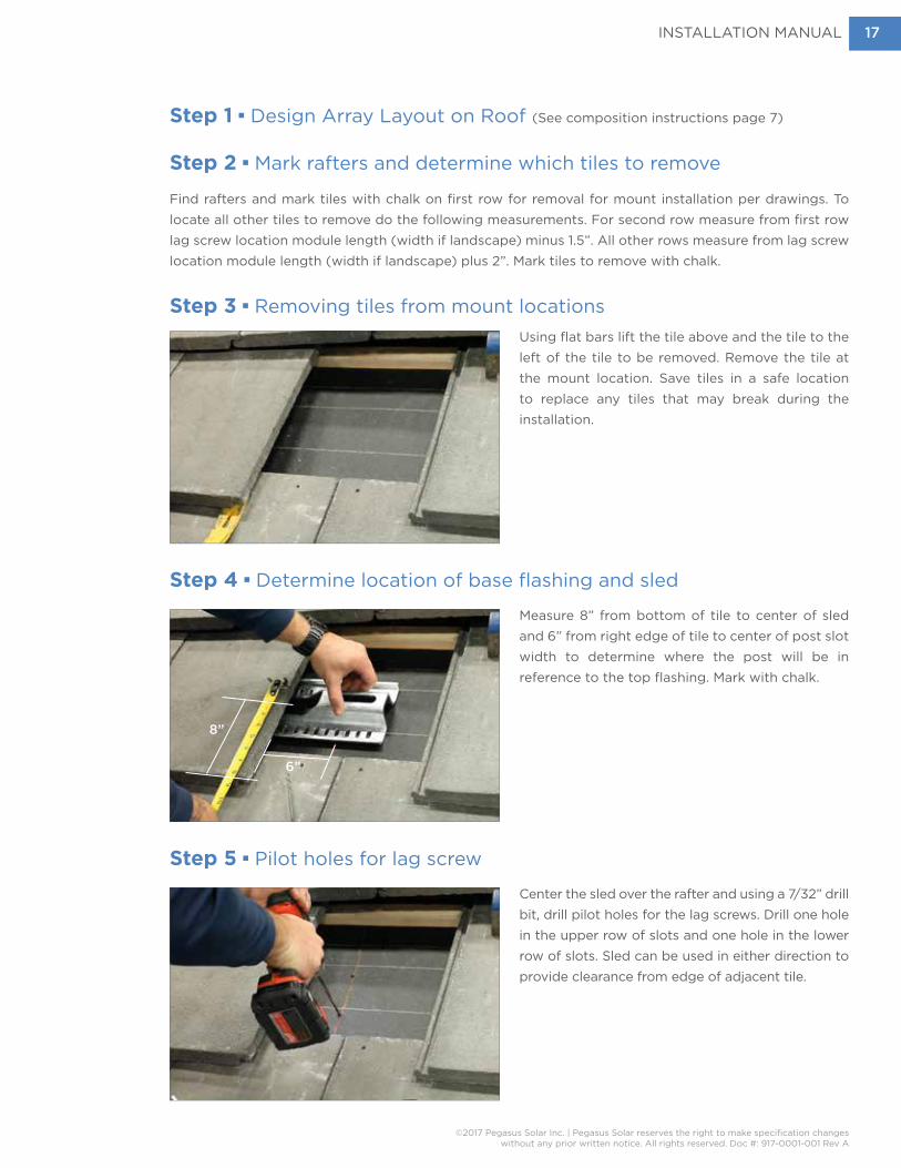
Step 1 n Design Array Layout on Roof (See composition instructions page 7)
Step 2 n Mark rafters and determine which tiles to remove
Find rafters and mark tiles with chalk on first row for removal for mount installation per drawings. To locate all other tiles to remove do the following measurements. For second row measure from first row lag screw location module length (width if landscape) minus 1.5”. All other rows measure from lag screw location module length (width if landscape) plus 2”. Mark tiles to remove with chalk.
Step 3 n Removing tiles from mount locations
Step 4 n Determine location of base flashing and sled
Step 5 n Pilot holes for lag screw
Using flat bars lift the tile above and the tile to the left of the tile to be removed. Remove the tile at the mount location. Save tiles in a safe location to replace any tiles that may break during the installation.
Measure 8” from bottom of tile to center of sled and 6” from right edge of tile to center of post slot width to determine where the post will be in reference to the top flashing. Mark with chalk.
Center the sled over the rafter and using a 7/32” drill bit, drill pilot holes for the lag screws. Drill one hole in the upper row of slots and one hole in the lower row of slots. Sled can be used in either direction to provide clearance from edge of adjacent tile.
8”
6”

INSTALLATION MANUAL
©2017 Pegasus Solar Inc. | Pegasus Solar reserves the right to make specification changeswithout any prior written notice. All rights reserved. Doc #: 917-0001-001 Rev A
18
Step 6 n Waterproof and Install Base Flashing (optional per local AHJ)
Fill pilot holes with approved sealant. Apply sealant in a U shape on the underside of the flashing. Place flashing over pilot holes for lag screws and press down. Waterproof per all applicable codes and standards as required by the AHJ.
Step 7 n Lag both flashing and sled to rafter
Step 8 n Install Tile Replacement Flashing
Place Sled in desired location over base flashing and lag screw upper and lower row using a standard impact drill.
Prop up the tile above the mount. Slide tile replace flashing in and align with surrounding tiles. Return tiles to original position.

INSTALLATION MANUAL
©2017 Pegasus Solar Inc. | Pegasus Solar reserves the right to make specification changeswithout any prior written notice. All rights reserved. Doc #: 917-0001-001 Rev A
19
Step 9 n Insert post through flashing and drop T-bolt into slot on sled.
Step 11 n Install Mount Assembly
Step 10 n Seal the post
Hand tighten post and follow with channel locks to secure post.
Turn the post until T-bolt grabs the sled.
Spin clamp assembly on to post a minimum of 4 turns or ½ inch. Maximum amount of turns onto base is 16 or 2 inches.
Run a bead of caulking where flashing meets post. Place Pegasus provided EPDM collar over the post.
Step 12 n Optional Extension Arm, if necessary
Use the Extension Arm to increase distance up/down the roof. Extension Arm can only be installed facing up or down the roof and must be within 5 degrees of a 12 o’clock or 6 o’clock position. Drop on to post and secure with a Corner Hinge Bolt tighten to 170 in-lb. Spin on Mount and level with adjacent mounts.
To complete array see page 10, Leveling Mount Assemblies and continue through page 15, Bonding and Grounding.
INSTALLATION MANUAL
©2017 Pegasus Solar Inc. | Pegasus Solar reserves the right to make specification changeswithout any prior written notice. All rights reserved. Doc #: 917-0001-001 Rev A
20
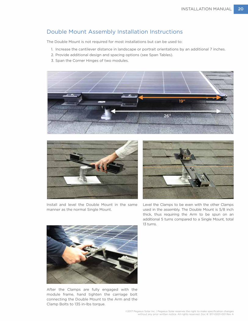
Double Mount Assembly Installation Instructions
The Double Mount is not required for most installations but can be used to:
1. Increase the cantilever distance in landscape or portrait orientations by an additional 7 inches.2. Provide additional design and spacing options (see Span Tables).3. Span the Corner Hinges of two modules.
Install and level the Double Mount in the same manner as the normal Single Mount.
Level the Clamps to be even with the other Clamps used in the assembly. The Double Mount is 5/8 inch thick, thus requiring the Arm to be spun on an additional 5 turns compared to a Single Mount, total 13 turns.
After the Clamps are fully engaged with the module frame, hand tighten the carriage bolt connecting the Double Mount to the Arm and the Clamp Bolts to 135 in-lbs torque.
26”
19”

INSTALLATION MANUAL
©2017 Pegasus Solar Inc. | Pegasus Solar reserves the right to make specification changeswithout any prior written notice. All rights reserved. Doc #: 917-0001-001 Rev A
21
Optional n Skirt Installation Instructions
The optional skirts come in portrait and landscape dimensions. They are secured to the mount assembly using the same nut that holds the Mount to the module.
Alternate Method of Bonding of Skirts
Install skirt by removing first row Mount nut, then place skirt over clamp. Tighten nut loosely. After modules are installed tighten clamp assemblies to 135 in-lbs
Attached the subsequent skirts in a tongue and groove fashion. Starting from one end to the other. The serrated nut will scrape the skirts surface creating a bond to the array.
Install a braided ground strap to either a corner hinge or clamping assembly and skirt, as described in the ILSCO SBJ-516-X (X is length) installation manual. Note: UL 2703 does NOT require skirts to be bonded, however bonding may be required by some Authorities Having Jurisdiction (AHJ’s).
INSTALLATION MANUAL
©2017 Pegasus Solar Inc. | Pegasus Solar reserves the right to make specification changeswithout any prior written notice. All rights reserved. Doc #: 917-0001-001 Rev A
22
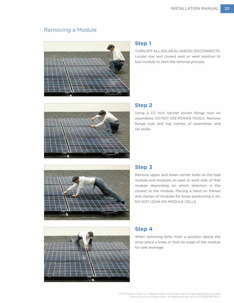
Removing a Module
Step 1TURN OFF ALL SOLAR AC AND DC DISCONNECTS. Locate row and closest east or west position to bad module to start the removal process.
Step 2Using a 1/2 inch ratchet loosen flange nuts on assemblies. DO NOT USE POWER TOOLS. Remove flange nuts and top clamps of assemblies and set aside.
Step 3Remove upper and lower corner bolts on the bad module and modules on east or west side of that module depending on which direction is the closest to the module. Placing a hand on frames and clamps of modules for body positioning is ok. DO NOT LEAN ON MODULE CELLS.
Step 4When removing bolts from a position above the array place a knee or foot on edge of the module for safe leverage.

INSTALLATION MANUAL
©2017 Pegasus Solar Inc. | Pegasus Solar reserves the right to make specification changeswithout any prior written notice. All rights reserved. Doc #: 917-0001-001 Rev A
23
Removing a Module continued
Step 5Gently pull the first module in the affected row toward you to release the corners. Disconnect all wires and set module aside.
Step 6Remove flange nuts and top clamps on the next module in the row per step 2. Repeat Step 5. Continue until non-performing module is removed.
INSTALLATION MANUAL
©2017 Pegasus Solar Inc. | Pegasus Solar reserves the right to make specification changeswithout any prior written notice. All rights reserved. Doc #: 917-0001-001 Rev A
24
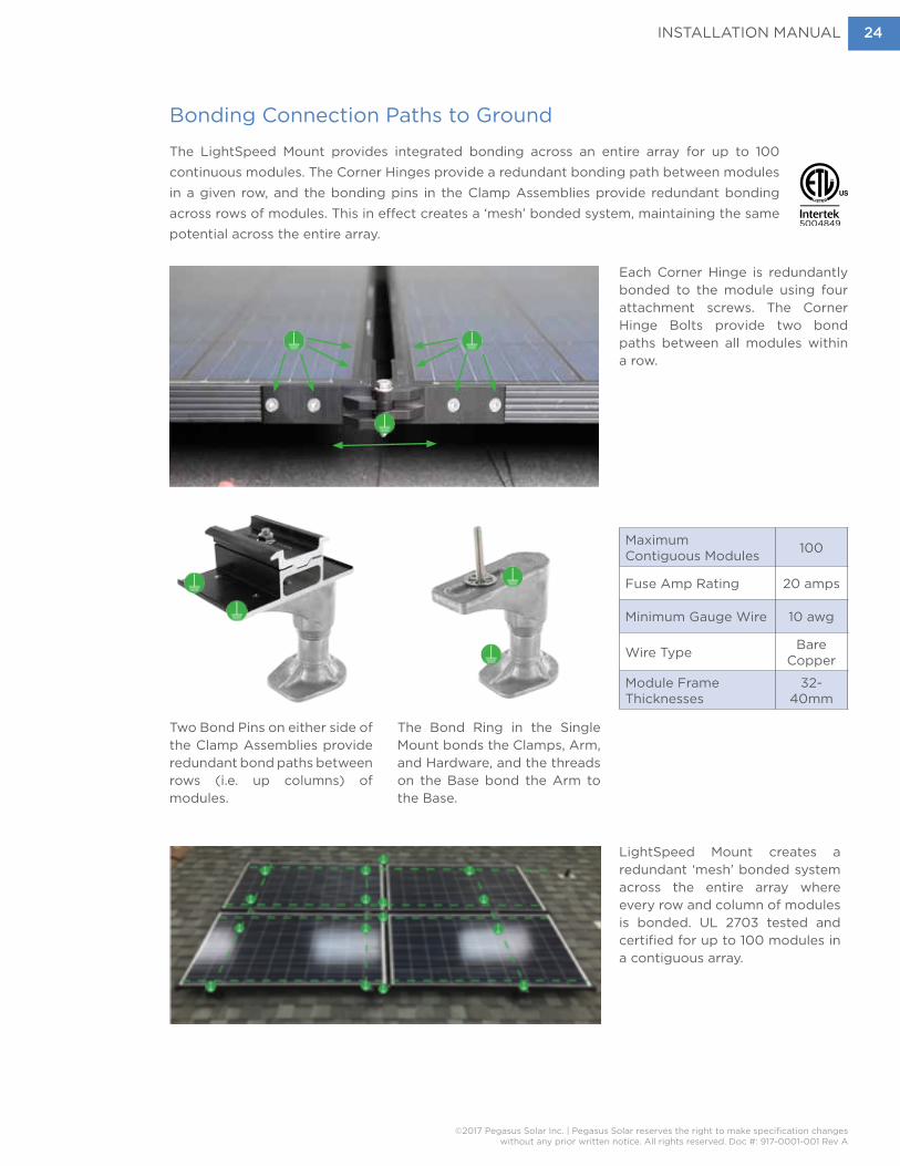
Bonding Connection Paths to Ground
The LightSpeed Mount provides integrated bonding across an entire array for up to 100 continuous modules. The Corner Hinges provide a redundant bonding path between modules in a given row, and the bonding pins in the Clamp Assemblies provide redundant bonding across rows of modules. This in effect creates a ‘mesh’ bonded system, maintaining the same potential across the entire array.
5004849
Each Corner Hinge is redundantly bonded to the module using four attachment screws. The Corner Hinge Bolts provide two bond paths between all modules within a row.
LightSpeed Mount creates a redundant ‘mesh’ bonded system across the entire array where every row and column of modules is bonded. UL 2703 tested and certified for up to 100 modules in a contiguous array.
Two Bond Pins on either side of the Clamp Assemblies provide redundant bond paths between rows (i.e. up columns) of modules.
The Bond Ring in the Single Mount bonds the Clamps, Arm, and Hardware, and the threads on the Base bond the Arm to the Base.
Maximum Contiguous Modules 100
Fuse Amp Rating 20 amps
Minimum Gauge Wire 10 awg
Wire Type Bare Copper
Module Frame Thicknesses
32-40mm

INSTALLATION MANUAL
©2017 Pegasus Solar Inc. | Pegasus Solar reserves the right to make specification changeswithout any prior written notice. All rights reserved. Doc #: 917-0001-001 Rev A
25
Bonding and Grounding the Array
Attach the grounding lug with a 5/16-inch connection hole to any corner hinge. Use a stainless steel serrated flange bolt for threaded corners or a stainless steel serrated flange bolt and nut on a non-threaded corner. Hand tighten the bolt to 135 in lbs. torque. Lay in equipment ground connector and tighten bolt to 5 ft.-lb. For connections at a joined corner bolt, use a nut. All bolted connection methods are UL 2703 tested and certified. WEEB Washers are not required with this system.
Run a NEC-compliant equipment grounding conductor from the ground lug to the junction box GEC. Keep copper away from aluminum and galvanized steel by securing bare copper conductors in a
fashion that maintains a minimum 1/4” separation.

INSTALLATION MANUAL
©2017 Pegasus Solar Inc. | Pegasus Solar reserves the right to make specification changeswithout any prior written notice. All rights reserved. Doc #: 917-0001-001 Rev A
26
Best Practice
• Verify site plans, rafter spacing, and measure working roof space upon arrival of each project to note if additional components are needed.
• Validate all material is on site including modules, mount assemblies, skirts, inverters, grounding lugs and wire management clips, per drawings.
• Initial layout of each array must be measured out correctly and chalk lined to keep straight horizontal rows of mounting assemblies. Double check before drilling.
• Mark module locations on the roof to verify rafter/corner hinge and assembly interference. Double mount assemblies span corner hinges directly over rafters.
• Tighten corner bolts and assemblies to correct torque’s and double check before leaving the project.
• Double check all wire management under arrays for code compliance.
• Be sure to insert skirts together fully and that they are level to the roof before tightening assemblies. Debris should be removed from skirts after installation.
Maintenance
Periodical inspections by qualified persons shall be performed. Following these mechanical checks;
• Check for loose clamp assemblies. If loose clamp assemblies are identified, re-tighten to the specifications above.
• Check for corrosion, if noticeable corrosion is identified that may compromise the safety or function of the mounting system, replace components immediately.
• Check for loose wires, wire clips or zip ties under the system.
• Check for roof damage around mounts, including water/wind damage or critter damage.
• Check for excessive debris under array and remove as necessary.

INSTALLATION MANUAL
©2017 Pegasus Solar Inc. | Pegasus Solar reserves the right to make specification changeswithout any prior written notice. All rights reserved. Doc #: 917-0001-001 Rev A
27
Troubleshooting Guide
Routine maintenance involving assembly torque checks, cleaning, and debris removal from under the modules will help keep the system running correctly. Attic inspections of the underside of the roof is recommended yearly, and in addition a licensed electrician is recommended to check components yearly to avoid possible issues within the electrical system.
Reviewing monitoring systems routinely can also identify issues earlier than later. Keep notes on any module or inverter alerts that may come up and notify your installation representative immediately. If any mounting components appear to be broken notify your installation representative immediately.
Removal of a Pegasus Solar System
Disconnect the main controlling breaker for the solar electric system, to include turning off all DC and
A/C disconnects before removing any components on the roof.
• NOTE - DO NOT USE A DRILL MOTOR TO REMOVE HARDWARE, GALLING MAY OCCUR!
• Loosen upper row of the LightSpeed assembly flange nuts on the array, do not remove. Then remove the corner bolts from the first two modules. Next, loosen the next lower row of LightSpeed assemblies and gently slide first module away from the array.
• STOP! Remember to now disconnect the first set of PV wires using a proper connection disconnect tool before removing module from the roof.
• Continue removing modules until only the assemblies are left. Next spin off each assembly to reveal the base, lag screw and flashing. Using a 1/2” socket and hammer drill, remove the lag screw from the rafter. Remove the base and the flashing.
• Flash and seal all roof penetrations
• Clean all assemblies and modules of debris or corrosive materials.
• Inspect all LightSpeed assemblies, corner hinges and hardware for irregularities or fractures during removal and note immediately.
• Please send any question by email to [email protected]

INSTALLATION MANUAL
©2017 Pegasus Solar Inc. | Pegasus Solar reserves the right to make specification changeswithout any prior written notice. All rights reserved. Doc #: 917-0001-001 Rev A
28
Torque and Pull-Out SpecsAppendix
ATorque Settings for LightSpeed Mount hardware
Bolt Torque (in-lbs) Torque (ft-lbs) Torque (N-m)
Corner Hinge Bolt 170 14.1 19.2
Single Mount Nut 135 11.3 15.3
Single Mount Nut w/Anti-Seize 112 9.3 12.6
Double Mount Nut 135 11.3 15.3
Double Mount Nut w/Anti-Seize 112 9.3 12.6
Ground Lug Attachment Bolt (or Nut) 120 10 13.6
Lag pull-out strengths in common lumber (lbs)Source: American Wood Council, NDS 2005, Table 11.2 A, 11.3.2 A
Wood Type Specific Gravity 5/16” Shaft per 3” Thread Depth
5/16” Shaft per 1” Thread Depth
Douglas Fir, Larch .50 798 266
Douglas Fir, South .46 705 235
Engelmann Spruce, Lodgepole Pine* .46 705 235
Hem, Fir .43 636 212
Hem, Fir (North) .46 705 235
Southern Pine .55 921 307
Spruce, Pine, Fir .42 615 205
Spruce, Pine, Fir** .50 798 266
* MSR 1650 f and higher.** E of 2 million PSI and higher grades of MSR and MEL.

INSTALLATION MANUAL
©2017 Pegasus Solar Inc. | Pegasus Solar reserves the right to make specification changeswithout any prior written notice. All rights reserved. Doc #: 917-0001-001 Rev A
29
LightSpeed Mount Compatible Modules for UL2703 Electrical Bonding/Grounding
Appendix
BPV Manufacturer Module Series
AU Optronics (BenQ) PM Series
Canadian
CS6X-P
CS6P-P
CS6P-M
CS6-M All Black
CS6-K
ET Solar ET Series
HanwhaHSL-60S
HSL-72S
Hyundai RF, RG, TF, TG, RI, TI-Series Series
Jinko JKM Series, MX60, MX72. MKT, Eagle
LGMono X
Neon
ReneSola JC Series
SolarWorld
SunModule Plus
SunModule Pro
SunModule Protect
SunModule XL
SunivaOPT 72 38mm
OPT 60 40mm, 35mm
TrinaPA05, PD05, PD14
TallMax
UpSolar UP-M Series
YingliYGE 60
Panda
INSTALLATION MANUAL
©2017 Pegasus Solar Inc. | Pegasus Solar reserves the right to make specification changeswithout any prior written notice. All rights reserved. Doc #: 917-0001-001 Rev A
30
Approved Module Load Characteristics
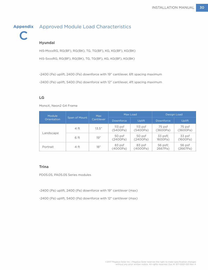
Hyundai
HiS-MxxxRG, RG(BF), RG(BK), TG, TG(BF), KG, KG(BF), KG(BK)
HiS-SxxxRG, RG(BF), RG(BK), TG, TG(BF), KG, KG(BF), KG(BK)
-2400 (Pa) uplift, 2400 (Pa) downforce with 19” cantilever, 6ft spacing maximum
-2400 (Pa) uplift, 5400 (Pa) downforce with 12” cantilever, 4ft spacing maximum
LG
MonoX, Neon2 G4 Frame
Module Orientation Span of Mount Max
Cantilever
Max Load Design Load
Downforce Uplift Downforce Uplift
Landscape4 ft 13.5” 113 psf
(5400Pa)113 psf
(5400Pa)75 psf
(3600Pa)75 psf
(3600Pa)
6 ft 19” 50 psf (2400Pa)
50 psf (2400Pa)
33 psf( 1600Pa)
33 psf (1600Pa)
Portrait 4 ft 18” 83 psf (4000Pa)
83 psf (4000Pa)
56 psf( 2667Pa)
56 psf (2667Pa)
Trina
PD05.05, PA05.05 Series modules
-2400 (Pa) uplift, 2400 (Pa) downforce with 19” cantilever (max)
-2400 (Pa) uplift, 5400 (Pa) downforce with 12” cantilever (max)
Appendix
C

INSTALLATION MANUAL
©2017 Pegasus Solar Inc. | Pegasus Solar reserves the right to make specification changeswithout any prior written notice. All rights reserved. Doc #: 917-0001-001 Rev A
31
Span TablesAppendix
D Landscape Orientation - ASCE 7-10 - Interior Mounts (3.29 ft Tributary Width)
SnowLoad
Exposure Category
Roof Angle
Roof Zone
Basic Wind Speed, V (mph)
110 115 120 125 130 140 150 160 170 1800
PS
F
B
0 to 7 Degrees
1 72 72 72 72 72 72 72 72 64 64
2 72 72 72 64 64 60 48 36 36 0
3 60 48 48 48 36 36 0 0 0 0
8 to 27 Degrees
1 72 72 72 72 72 72 72 72 72 64
2 72 72 72 72 64 60 48 48 36 36
3 64 60 48 48 48 36 0 0 0 0
28 to 45 Degrees
1 72 72 72 72 72 72 72 64 64 60
2 72 72 72 72 72 72 64 64 48 48
3 72 72 72 72 72 72 64 64 48 48
C
0 to 7 Degrees
1 72 72 72 72 72 64 64 60 48 48
2 64 64 60 48 48 36 0 0 0 0
3 36 36 36 0 0 0 0 0 0 0
8 to 27 Degrees
1 72 72 72 72 72 72 64 64 48 48
2 64 64 60 48 48 36 36 0 0 0
3 48 36 36 0 0 0 0 0 0 0
28 to 45 Degrees
1 72 72 72 72 72 64 64 48 48 36
2 72 72 72 72 64 60 48 36 36 36
3 72 72 72 72 64 60 48 36 36 36
D
0 to 7 Degrees
1 72 72 72 72 64 64 48 48 36 36
2 60 48 48 36 36 0 0 0 0 0
3 36 0 0 0 0 0 0 0 0 0
8 to 27 Degrees
1 72 72 72 72 72 64 60 48 48 36
2 60 48 48 48 36 36 0 0 0 0
3 36 0 0 0 0 0 0 0 0 0
28 to 45 Degrees
1 72 72 72 64 64 60 48 48 36 36
2 72 72 64 64 60 48 36 36 0 0
3 72 72 64 64 60 48 36 36 0 0
1-15
PS
F
B
0 to 7 Degrees
1 72 72 72 72 72 72 72 72 64 64
2 72 72 72 64 64 60 48 36 36 0
3 60 48 48 48 36 36 0 0 0 0
8 to 27 Degrees
1 72 72 72 72 72 72 72 72 64 64
2 72 72 72 72 64 60 48 48 36 36
3 64 60 48 48 48 36 0 0 0 0
28 to 45 Degrees
1 72 72 72 72 72 72 72 64 64 60
2 72 72 72 72 72 72 64 64 48 48
3 72 72 72 72 72 72 64 64 48 48
C
0 to 7 Degrees
1 72 72 72 72 72 64 64 60 48 48
2 64 64 60 48 48 36 0 0 0 0
3 36 36 36 0 0 0 0 0 0 0
8 to 27 Degrees
1 72 72 72 72 72 64 64 64 48 48
2 64 64 60 48 48 36 36 0 0 0
3 48 36 36 0 0 0 0 0 0 0
28 to 45 Degrees
1 72 72 72 72 72 64 64 48 48 36
2 72 72 72 72 64 60 48 36 36 36
3 72 72 72 72 64 60 48 36 36 36
D
0 to 7 Degrees
1 72 72 72 72 64 64 48 48 36 36
2 60 48 48 36 36 0 0 0 0 0
3 36 0 0 0 0 0 0 0 0 0
8 to 27 Degrees
1 72 72 72 72 64 64 60 48 48 36
2 60 48 48 48 36 36 0 0 0 0
3 36 0 0 0 0 0 0 0 0 0
28 to 45 Degrees
1 72 72 72 64 64 60 48 48 36 36
72 72 64 64 60 48 36 36 0 0
3 72 72 64 64 60 48 36 36 0 0

INSTALLATION MANUAL
©2017 Pegasus Solar Inc. | Pegasus Solar reserves the right to make specification changeswithout any prior written notice. All rights reserved. Doc #: 917-0001-001 Rev A
32
Span TablesAppendix
D Landscape Orientation - ASCE 7-10 - Interior Mounts (3.29 ft Tributary Width)
SnowLoad
Exposure Category
Roof Angle
Roof Zone
Basic Wind Speed, V (mph)
110 115 120 125 130 140 150 160 170 18016
-20
PS
F
B
0 to 7 Degrees
1 64 64 64 64 64 64 64 64 64 64
2 64 64 64 64 64 60 48 36 36 0
3 60 48 48 48 36 36 0 0 0 0
8 to 27 Degrees
1 64 64 64 64 64 64 64 64 64 64
2 64 64 64 64 64 60 48 48 36 36
3 64 60 48 48 48 36 0 0 0 0
28 to 45 Degrees
1 72 72 72 72 72 72 64 64 64 60
2 72 72 72 72 72 72 64 64 48 48
3 72 72 72 72 72 72 64 64 48 48
C
0 to 7 Degrees
1 64 64 64 64 64 64 64 60 48 48
2 64 64 60 48 48 36 0 0 0 0
3 36 36 36 0 0 0 0 0 0 0
8 to 27 Degrees
1 64 64 64 64 64 64 64 60 48 48
2 64 64 60 48 48 36 36 0 0 0
3 48 36 36 0 0 0 0 0 0 0
28 to 45 Degrees
1 72 72 72 72 64 64 64 48 48 36
2 72 72 72 72 64 60 48 36 36 36
3 72 72 72 72 64 60 48 36 36 36
D
0 to 7 Degrees
1 64 64 64 64 64 64 48 48 36 36
2 60 48 48 36 36 0 0 0 0 0
3 36 0 0 0 0 0 0 0 0 0
8 to 27 Degrees
1 64 64 64 64 64 64 60 48 48 36
2 60 48 48 48 36 36 0 0 0 0
3 36 0 0 0 0 0 0 0 0 0
28 to 45 Degrees
1 72 72 64 64 64 60 48 48 36 36
2 72 72 64 64 60 48 36 36 0 0
3 72 72 64 64 60 48 36 36 0 0
21-
25
PS
F
B
0 to 7 Degrees
1 64 64 64 64 64 64 64 64 64 64
2 64 64 64 64 64 60 48 36 36 0
3 60 48 48 48 36 36 0 0 0 0
8 to 27 Degrees
1 64 64 64 64 64 64 64 64 64 60
2 64 64 64 64 64 60 48 48 36 36
3 64 60 48 48 48 36 0 0 0 0
28 to 45 Degrees
1 72 72 72 72 72 72 64 64 64 60
2 72 72 72 72 72 72 64 64 48 48
3 72 72 72 72 72 72 64 64 48 48
C
0 to 7 Degrees
1 64 64 64 64 64 64 64 60 48 48
2 64 64 60 48 48 36 0 0 0 0
3 36 36 36 0 0 0 0 0 0 0
8 to 27 Degrees
1 64 64 64 64 64 64 64 60 48 48
2 64 64 60 48 48 36 36 0 0 0
3 48 36 36 0 0 0 0 0 0 0
28 to 45 Degrees
1 72 72 72 64 64 64 60 48 48 36
2 72 72 72 64 64 60 48 36 36 36
3 72 72 72 64 64 60 48 36 36 36
D
0 to 7 Degrees
1 64 64 64 64 64 64 48 48 36 36
2 60 48 48 36 36 0 0 0 0 0
3 36 0 0 0 0 0 0 0 0 0
8 to 27 Degrees
1 64 64 64 64 64 60 60 48 48 36
2 60 48 48 48 36 36 0 0 0 0
3 36 0 0 0 0 0 0 0 0 0
28 to 45 Degrees
1 72 64 64 64 64 60 48 48 36 36
2 72 64 64 64 60 48 36 36 0 0
3 72 64 64 64 60 48 36 36 0 0

INSTALLATION MANUAL
©2017 Pegasus Solar Inc. | Pegasus Solar reserves the right to make specification changeswithout any prior written notice. All rights reserved. Doc #: 917-0001-001 Rev A
33
Span TablesAppendix
D Landscape Orientation - ASCE 7-10 - Interior Mounts (3.29 ft Tributary Width)
SnowLoad
Exposure Category
Roof Angle
Roof Zone
Basic Wind Speed, V (mph)
110 115 120 125 130 140 150 160 170 1802
6-3
0 P
SF
B
0 to 7 Degrees
1 64 64 64 64 64 64 64 64 64 64
2 64 64 64 64 64 60 48 36 36 0
3 60 48 48 48 36 36 0 0 0 0
8 to 27 Degrees
1 64 64 64 64 64 64 64 60 60 60
2 64 64 64 64 64 60 48 48 36 36
3 64 60 48 48 48 36 0 0 0 0
28 to 45 Degrees
1 72 72 72 72 72 64 64 64 64 60
2 72 72 72 72 72 64 64 64 48 48
3 72 72 72 72 72 64 64 64 48 48
C
0 to 7 Degrees
1 64 64 64 64 64 64 64 60 48 48
2 64 64 60 48 48 36 0 0 0 0
3 36 36 36 0 0 0 0 0 0 0
8 to 27 Degrees
1 64 64 64 64 60 60 60 48 48 48
2 64 64 60 48 48 36 36 0 0 0
3 48 36 36 0 0 0 0 0 0 0
28 to 45 Degrees
1 72 72 64 64 64 64 60 48 48 36
2 72 72 64 64 64 60 48 36 36 36
3 72 72 64 64 64 60 48 36 36 36
D
0 to 7 Degrees
1 64 64 64 64 64 64 48 48 36 36
2 60 48 48 36 36 0 0 0 0 0
3 36 0 0 0 0 0 0 0 0 0
8 to 27 Degrees
1 64 64 60 60 60 60 48 48 48 36
2 60 48 48 48 36 36 0 0 0 0
3 36 0 0 0 0 0 0 0 0 0
28 to 45 Degrees
1 64 64 64 64 64 60 48 48 36 36
2 64 64 64 64 60 48 36 36 0 0
3 64 64 64 64 60 48 36 36 0 0
31-
35
PS
F
B
0 to 7 Degrees
1 60 60 60 60 60 60 60 60 60 60
2 60 60 60 60 60 60 48 36 36 0
3 60 48 48 48 36 36 0 0 0 0
8 to 27 Degrees
1 60 60 60 60 60 60 60 48 48 48
2 60 60 60 60 60 60 48 48 36 36
3 60 60 48 48 48 36 0 0 0 0
28 to 45 Degrees
1 72 72 72 72 72 64 64 64 60 60
2 72 72 72 72 72 64 64 64 48 48
3 72 72 72 72 72 64 64 64 48 48
C
0 to 7 Degrees
1 60 60 60 60 60 60 60 60 48 48
2 60 60 60 48 48 36 0 0 0 0
3 36 36 36 0 0 0 0 0 0 0
8 to 27 Degrees
1 60 60 60 60 60 48 48 48 48 48
2 60 60 60 48 48 36 36 0 0 0
3 48 36 36 0 0 0 0 0 0 0
28 to 45 Degrees
1 64 64 64 64 64 60 60 48 48 36
2 64 64 64 64 64 60 48 36 36 36
3 64 64 64 64 64 60 48 36 36 36
D
0 to 7 Degrees
1 60 60 60 60 60 60 48 48 36 36
2 60 48 48 36 36 0 0 0 0 0
3 36 0 0 0 0 0 0 0 0 0
8 to 27 Degrees
1 60 60 60 48 48 48 48 48 48 36
2 60 48 48 48 36 36 0 0 0 0
3 36 0 0 0 0 0 0 0 0 0
28 to 45 Degrees
1 64 64 64 64 60 60 48 48 36 36
2 64 64 64 64 60 48 36 36 0 0
3 64 64 64 64 60 48 36 36 0 0
INSTALLATION MANUAL
©2017 Pegasus Solar Inc. | Pegasus Solar reserves the right to make specification changeswithout any prior written notice. All rights reserved. Doc #: 917-0001-001 Rev A
34
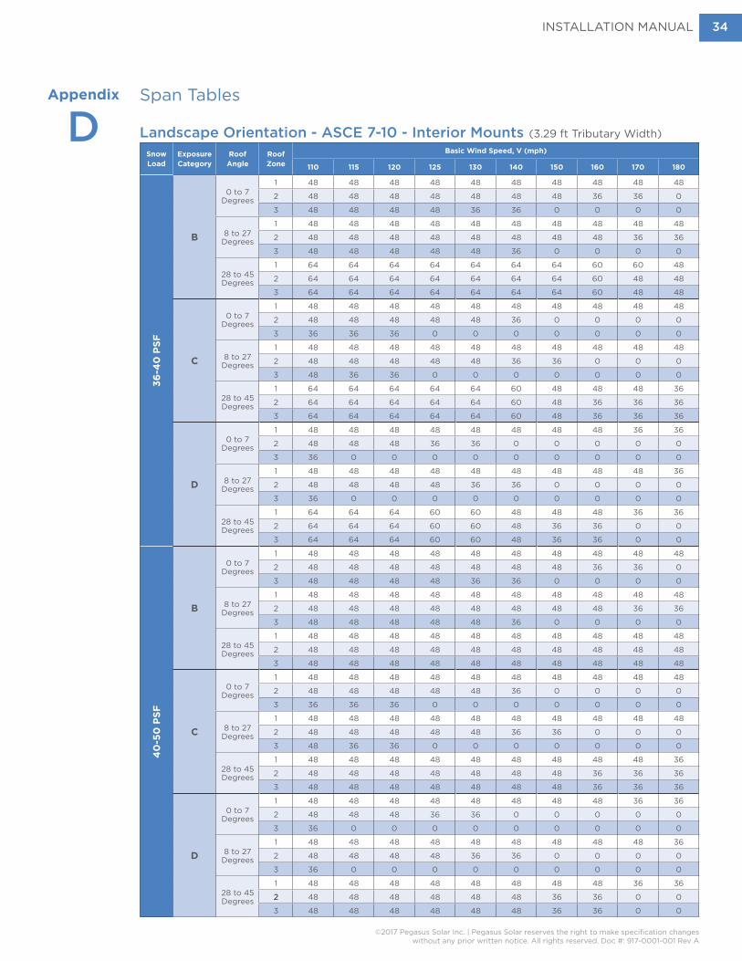
Span TablesAppendix
D Landscape Orientation - ASCE 7-10 - Interior Mounts (3.29 ft Tributary Width)
SnowLoad
Exposure Category
Roof Angle
Roof Zone
Basic Wind Speed, V (mph)
110 115 120 125 130 140 150 160 170 1803
6-4
0 P
SF
B
0 to 7 Degrees
1 48 48 48 48 48 48 48 48 48 48
2 48 48 48 48 48 48 48 36 36 0
3 48 48 48 48 36 36 0 0 0 0
8 to 27 Degrees
1 48 48 48 48 48 48 48 48 48 48
2 48 48 48 48 48 48 48 48 36 36
3 48 48 48 48 48 36 0 0 0 0
28 to 45 Degrees
1 64 64 64 64 64 64 64 60 60 48
2 64 64 64 64 64 64 64 60 48 48
3 64 64 64 64 64 64 64 60 48 48
C
0 to 7 Degrees
1 48 48 48 48 48 48 48 48 48 48
2 48 48 48 48 48 36 0 0 0 0
3 36 36 36 0 0 0 0 0 0 0
8 to 27 Degrees
1 48 48 48 48 48 48 48 48 48 48
2 48 48 48 48 48 36 36 0 0 0
3 48 36 36 0 0 0 0 0 0 0
28 to 45 Degrees
1 64 64 64 64 64 60 48 48 48 36
2 64 64 64 64 64 60 48 36 36 36
3 64 64 64 64 64 60 48 36 36 36
D
0 to 7 Degrees
1 48 48 48 48 48 48 48 48 36 36
2 48 48 48 36 36 0 0 0 0 0
3 36 0 0 0 0 0 0 0 0 0
8 to 27 Degrees
1 48 48 48 48 48 48 48 48 48 36
2 48 48 48 48 36 36 0 0 0 0
3 36 0 0 0 0 0 0 0 0 0
28 to 45 Degrees
1 64 64 64 60 60 48 48 48 36 36
2 64 64 64 60 60 48 36 36 0 0
3 64 64 64 60 60 48 36 36 0 0
40
-50
PS
F
B
0 to 7 Degrees
1 48 48 48 48 48 48 48 48 48 48
2 48 48 48 48 48 48 48 36 36 0
3 48 48 48 48 36 36 0 0 0 0
8 to 27 Degrees
1 48 48 48 48 48 48 48 48 48 48
2 48 48 48 48 48 48 48 48 36 36
3 48 48 48 48 48 36 0 0 0 0
28 to 45 Degrees
1 48 48 48 48 48 48 48 48 48 48
2 48 48 48 48 48 48 48 48 48 48
3 48 48 48 48 48 48 48 48 48 48
C
0 to 7 Degrees
1 48 48 48 48 48 48 48 48 48 48
2 48 48 48 48 48 36 0 0 0 0
3 36 36 36 0 0 0 0 0 0 0
8 to 27 Degrees
1 48 48 48 48 48 48 48 48 48 48
2 48 48 48 48 48 36 36 0 0 0
3 48 36 36 0 0 0 0 0 0 0
28 to 45 Degrees
1 48 48 48 48 48 48 48 48 48 36
2 48 48 48 48 48 48 48 36 36 36
3 48 48 48 48 48 48 48 36 36 36
D
0 to 7 Degrees
1 48 48 48 48 48 48 48 48 36 36
2 48 48 48 36 36 0 0 0 0 0
3 36 0 0 0 0 0 0 0 0 0
8 to 27 Degrees
1 48 48 48 48 48 48 48 48 48 36
2 48 48 48 48 36 36 0 0 0 0
3 36 0 0 0 0 0 0 0 0 0
28 to 45 Degrees
1 48 48 48 48 48 48 48 48 36 36
2 48 48 48 48 48 48 36 36 0 0
3 48 48 48 48 48 48 36 36 0 0

INSTALLATION MANUAL
©2017 Pegasus Solar Inc. | Pegasus Solar reserves the right to make specification changeswithout any prior written notice. All rights reserved. Doc #: 917-0001-001 Rev A
35
Span TablesAppendix
D Landscape Orientation - ASCE 7-10 - Interior Mounts (3.29 ft Tributary Width)
SnowLoad
Exposure Category
Roof Angle
Roof Zone
Basic Wind Speed, V (mph)
110 115 120 125 130 140 150 160 170 1805
1-70
PS
F
B
0 to 7 Degrees
1 36 36 36 36 36 36 36 36 36 36
2 36 36 36 36 36 36 36 36 36 0
3 36 36 36 36 36 36 0 0 0 0
8 to 27 Degrees
1 36 36 36 36 36 36 36 36 36 36
2 36 36 36 36 36 36 36 36 36 36
3 36 36 36 36 36 36 0 0 0 0
28 to 45 Degrees
1 36 36 36 36 36 36 36 36 36 36
2 36 36 36 36 36 36 36 36 36 36
3 36 36 36 36 36 36 36 36 36 36
C
0 to 7 Degrees
1 36 36 36 36 36 36 36 36 36 36
2 36 36 36 36 36 36 0 0 0 0
3 36 36 36 0 0 0 0 0 0 0
8 to 27 Degrees
1 36 36 36 36 36 36 36 36 36 36
2 36 36 36 36 36 36 36 0 0 0
3 36 36 36 0 0 0 0 0 0 0
28 to 45 Degrees
1 36 36 36 36 36 36 36 36 36 36
2 36 36 36 36 36 36 36 36 36 36
3 36 36 36 36 36 36 36 36 36 36
D
0 to 7 Degrees
1 36 36 36 36 36 36 36 36 36 36
2 36 36 36 36 36 0 0 0 0 0
3 36 0 0 0 0 0 0 0 0 0
8 to 27 Degrees
1 36 36 36 36 36 36 36 36 36 36
2 36 36 36 36 36 36 0 0 0 0
3 36 0 0 0 0 0 0 0 0 0
28 to 45 Degrees
1 36 36 36 36 36 36 36 36 36 36
2 36 36 36 36 36 36 36 36 0 0
3 36 36 36 36 36 36 36 36 0 0
71-
90
PS
F
B
0 to 7 Degrees
1 36 36 36 36 36 36 36 36 36 36
2 36 36 36 36 36 36 36 36 36 0
3 36 36 36 36 36 36 0 0 0 0
8 to 27 Degrees
1 24 24 24 24 24 24 24 24 24 24
2 24 24 24 24 24 24 24 24 24 24
3 24 24 24 24 24 24 0 0 0 0
28 to 45 Degrees
1 32 32 32 32 32 32 32 32 32 32
2 32 32 32 32 32 32 32 32 32 32
3 32 32 32 32 32 32 32 32 32 32
C
0 to 7 Degrees
1 36 36 36 36 36 36 36 36 36 36
2 36 36 36 36 36 36 0 0 0 0
3 36 36 36 0 0 0 0 0 0 0
8 to 27 Degrees
1 24 24 24 24 24 24 24 24 24 24
2 24 24 24 24 24 24 24 0 0 0
3 24 24 24 0 0 0 0 0 0 0
28 to 45 Degrees
1 32 32 32 32 32 32 32 32 32 32
2 32 32 32 32 32 32 32 32 32 32
3 32 32 32 32 32 32 32 32 32 32
D
0 to 7 Degrees
1 36 36 36 36 36 36 36 36 36 36
2 36 36 36 36 36 0 0 0 0 0
3 36 0 0 0 0 0 0 0 0 0
8 to 27 Degrees
1 24 24 24 24 24 24 24 24 24 24
2 24 24 24 24 24 24 0 0 0 0
3 24 0 0 0 0 0 0 0 0 0
28 to 45 Degrees
1 32 32 32 32 32 32 32 32 32 32
2 32 32 32 32 32 32 32 32 0 0
3 32 32 32 32 32 32 32 32 0 0

INSTALLATION MANUAL
©2017 Pegasus Solar Inc. | Pegasus Solar reserves the right to make specification changeswithout any prior written notice. All rights reserved. Doc #: 917-0001-001 Rev A
36
Span TablesAppendix
D Portrait Orientation - ASCE 7-10 - Interior Mounts (5.5 ft Tributary Width)
SnowLoad
Exposure Category
Roof Angle
Roof Zone
Basic Wind Speed, V (mph)
110 115 120 125 130 140 150 160 170 1800
PS
F
B
0 to 7 Degrees
1 48 /*72 48 /*72 48 /*72 48 /*72 48 /*72 48 /*64 48 /*60 48 36 36
2 48 /*60 48 48 36 36 36 32 24 24 16
3 36 32 32 24 24 16 16 16 16 12
8 to 27 Degrees
1 48 /*72 48 /*72 48 /*72 48 /*72 48 /*72 48 /*72 48 /*60 48 48 36
2 48 /*60 48 48 36 36 36 32 24 24 16
3 36 36 32 24 24 24 16 16 16 12
28 to 45 Degrees
1 48 /*72 48 /*72 48 /*72 48 /*72 48 /*64 48 /*60 48 36 36 36
2 48 /*72 48 /*72 48 /*64 48 /*60 48 48 36 36 32 24
3 48 /*72 48 /*72 48 /*64 48 /*60 48 48 36 36 32 24
C
0 to 7 Degrees
1 48 /*72 48 /*72 48 /*64 48 /*60 48 48 36 36 32 24
2 36 36 36 32 24 24 16 16 16 12
3 24 24 16 16 16 16 12 12 0 0
8 to 27 Degrees
1 48 /*72 48 /*72 48 /*64 48 /*64 48 48 36 36 32 24
2 36 36 36 32** 24** 24 16 16 16 16
3 24 24 24 16 16 16 12 12 12 0
28 to 45 Degrees
1 48 /*64 48 /*60 48 48 48 36 36 32 24 24
2 48 48 48 36 36 36 32 24 24 16
3 48 48 48 36 36 36 32 24 24 16
D
0 to 7 Degrees
1 48 /*64 48 /*60 48 48 48 36 32 24 24 24
2 36 32 24 24 24 16 16 16 12 12
3 16 16 16 16 16 12 12 0 0 0
8 to 27 Degrees
1 48 /*64 48 /*64 48 48 48 36 36 32 24 24
2 36 32 24 24 24 16 16 16 12 12
3 24 16 16 16 16 12 12 0 0 0
28 to 45 Degrees
1 48 48 48 36 36 36 32 24 24 16
2 48 36 36 36 36 24 24 24 16 16
3 48 36 36 36 36 24 24 24 16 16
1-15
PS
F
B
0 to 7 Degrees
1 48 /*72 48 /*72 48 /*72 48 /*72 48 /*72 48 /*64 48 /*60 48 36 36
2 48 /*60 48 48 36 36 36 32 24 24 16
3 36 32 32 24 24 16 16 16 16 12
8 to 27 Degrees
1 48 /*72 48 /*72 48 /*72 48 /*72 48 /*72 48 /*72 48 /*60 48 48 36
2 48 /*60 48 48 36 36 36 32 24 24 16
3 36 36 32 24 24 24 16 16 16 12
28 to 45 Degrees
1 48 /*72 48 /*72 48 /*72 48 /*72 48 /*64 48 /*60 48 36 36 36
2 48 /*72 48 /*72 48 /*64 48 /*60 48 48 36 36 32 24
3 48 /*72 48 /*72 48 /*64 48 /*60 48 48 36 36 32 24
C
0 to 7 Degrees
1 48 /*72 48 /*72 48 /*64 48 /*60 48 48 36 36 32 24
2 36 36 36 32 24 24 16 16 16 12
3 24 24 16 16 16 16 12 12 0 0
8 to 27 Degrees
1 48 /*72 48 /*72 48 /*64 48 /*64 48 48 36 36 32 24
2 36 36 36 32** 24** 24 16 16 16 16
3 24 24 24 16 16 16 12 12 12 0
28 to 45 Degrees
1 48 /*64 48 /*60 48 48 48 36 36 32 24 24
2 48 48 48 36 36 36 32 24 24 16
3 48 48 48 36 36 36 32 24 24 16
D
0 to 7 Degrees
1 48 /*64 48 /*60 48 48 48 36 32 24 24 24
2 36 32 24 24 24 16 16 16 12 12
3 16 16 16 16 16 12 12 0 0 0
8 to 27 Degrees
1 48 /*64 48 /*64 48 48 48 36 36 32 24 24
2 36 32 24 24 24 16 16 16 12 12
3 24 16 16 16 16 12 12 0 0 0
28 to 45 Degrees
1 48 48 48 36 36 36 32 24 24 16
2 48 36 36 36 36 24 24 24 16 16
3 48 36 36 36 36 24 24 24 16 16

INSTALLATION MANUAL
©2017 Pegasus Solar Inc. | Pegasus Solar reserves the right to make specification changeswithout any prior written notice. All rights reserved. Doc #: 917-0001-001 Rev A
37
Span TablesAppendix
D Portrait Orientation - ASCE 7-10 - Interior Mounts (5.5 ft Tributary Width)
SnowLoad
Exposure Category
Roof Angle
Roof Zone
Basic Wind Speed, V (mph)
110 115 120 125 130 140 150 160 170 18016
-20
PS
F
B
0 to 7 Degrees
1 48 /*64 48 /*64 48 /*64 48 /*64 48 /*64 48 /*64 48 /*60 48 36 36
2 48 /*60 48 48 36 36 36 32 24 24 16
3 36 32 32 24 24 16 16 16 16 12
8 to 27 Degrees
1 48 /*60 48 /*60 48 /*60 48 /*60 48 /*60 48 /*60 48 /*60 48 48 36
2 48 /*60 48 48 36 36 36 32 24 24 16
3 36 36 32 24 24 24 16 16 16 12
28 to 45 Degrees
1 48 /*64 48 /*64 48 /*64 48 /*64 48 /*64 48 /*60 48 36 36 36
2 48 /*64 48 /*64 48 /*64 48 /*60 48 48 36 36 32 24
3 48 /*64 48 /*64 48 /*64 48 /*60 48 48 36 36 32 24
C
0 to 7 Degrees
1 48 /*64 48 /*64 48 /*64 48 /*60 48 48 36 36 32 24
2 36 36 36 32 24 24 16 16 16 12
3 24 24 16 16 16 16 12 12 0 0
8 to 27 Degrees
1 48 /*60 48 /*60 48 /*60 48 /*60 48 48 36 36 32 24
2 36 36 36 32** 24** 24 16 16 16 16
3 24 24 24 16 16 16 12 12 12 0
28 to 45 Degrees
1 48 /*64 48 /*60 48 48 48 36 36 32 24 24
2 48 48 48 36 36 36 32 24 24 16
3 48 48 48 36 36 36 32 24 24 16
D
0 to 7 Degrees
1 48 /*64 48 /*60 48 48 48 36 32 24 24 24
2 36 32 24 24 24 16 16 16 12 12
3 16 16 16 16 16 12 12 0 0 0
8 to 27 Degrees
1 48 /*60 48 /*60 48 48 48 36 36 32 24 24
2 36 32 24 24 24 16 16 16 12 12
3 24 16 16 16 16 12 12 0 0 0
28 to 45 Degrees
1 48 48 48 36 36 36 32 24 24 16
2 48 36 36 36 36 24 24 24 16 16
3 48 36 36 36 36 24 24 24 16 16
21-
25
PS
F
B
0 to 7 Degrees
1 48 /*64 48 /*64 48 /*64 48 /*64 48 /*64 48 /*64 48 /*60 48 36 36
2 48 /*60 48 48 36 36 36 32 24 24 16
3 36 32 32 24 24 16 16 16 16 12
8 to 27 Degrees
1 48 /*60 48 /*60 48 /*60 48 /*60 48 /*60 48 /*60 48 /*60 48 48 36
2 48 /*60 48 48 36 36 36 32 24 24 16
3 36 36 32 24 24 24 16 16 16 12
28 to 45 Degrees
1 48 /*60 48 /*60 48 /*60 48 /*60 48 /*60 48 /*60 48 36 36 36
2 48 /*60 48 /*60 48 /*60 48 /*60 48 48 36 36 32 24
3 48 /*60 48 /*60 48 /*60 48 /*60 48 48 36 36 32 24
C
0 to 7 Degrees
1 48 /*64 48 /*64 48 /*64 48 /*60 48 48 36 36 32 24
2 36 36 36 32 24 24 16 16 16 12
3 24 24 16 16 16 16 12 12 0 0
8 to 27 Degrees
1 48 /*60 48 /*60 48 /*60 48 /*60 48 48 36 36 32 24
2 36 36 36 32** 24** 24 16 16 16 16
3 24 24 24 16 16 16 12 12 12 0
28 to 45 Degrees
1 48 /*60 48 /*60 48 48 48 36 36 32 24 24
2 48 48 48 36 36 36 32 24 24 16
3 48 48 48 36 36 36 32 24 24 16
D
0 to 7 Degrees
1 48 /*64 48 /*60 48 48 48 36 32 24 24 24
2 36 32 24 24 24 16 16 16 12 12
3 16 16 16 16 16 12 12 0 0 0
8 to 27 Degrees
1 48 /*60 48 /*60 48 48 48 36 36 32 24 24
2 36 32 24 24 24 16 16 16 12 12
3 24 16 16 16 16 12 12 0 0 0
28 to 45 Degrees
1 48 48 48 36 36 36 32 24 24 16
2 48 36 36 36 36 24 24 24 16 16
3 48 36 36 36 36 24 24 24 16 16

INSTALLATION MANUAL
©2017 Pegasus Solar Inc. | Pegasus Solar reserves the right to make specification changeswithout any prior written notice. All rights reserved. Doc #: 917-0001-001 Rev A
38
Span TablesAppendix
D Portrait Orientation - ASCE 7-10 - Interior Mounts (5.5 ft Tributary Width)
SnowLoad
Exposure Category
Roof Angle
Roof Zone
Basic Wind Speed, V (mph)
110 115 120 125 130 140 150 160 170 1802
6-3
0 P
SF
B
0 to 7 Degrees
1 48 /*64 48 /*64 48 /*64 48 /*64 48 /*64 48 /*64 48 /*60 48 36 36
2 48 /*60 48 48 36 36 36 32 24 24 16
3 36 32 32 24 24 16 16 16 16 12
8 to 27 Degrees
1 48 48 48 48 48 48 48 48 36 36
2 48 48 48 36 36 36 32 24 24 16
3 36 36 32 24 24 24 16 16 16 12
28 to 45 Degrees
1 48 48 48 48 48 48 48 36 36 36
2 48 48 48 48 48 48 36 36 32 24
3 48 48 48 48 48 48 36 36 32 24
C
0 to 7 Degrees
1 48 /*64 48 /*64 48 /*64 48 /*60 48 48 36 36 32 24
2 36 36 36 32 24 24 16 16 16 12
3 24 24 16 16 16 16 12 12 0 0
8 to 27 Degrees
1 48 48 48 48 48 48 36 36 32 24
2 36 36 36 32** 24** 24 16 16 16 16
3 24 24 24 16 16 16 12 12 12 0
28 to 45 Degrees
1 48 48 48 48 48 36 36 32 24 24
2 48 48 48 36 36 36 32 24 24 16
3 48 48 48 36 36 36 32 24 24 16
D
0 to 7 Degrees
1 48 /*64 48 /*60 48 48 48 36 32 24 24 24
2 36 32 24 24 24 16 16 16 12 12
3 16 16 16 16 16 12 12 0 0 0
8 to 27 Degrees
1 48 48 48 48 48 36 36 32 24 24
2 36 32 24 24 24 16 16 16 12 12
3 24 16 16 16 16 12 12 0 0 0
28 to 45 Degrees
1 48 48 48 36 36 36 32 24 24 16
2 48 36 36 36 36 24 24 24 16 16
3 48 36 36 36 36 24 24 24 16 16
31-
35
PS
F
B
0 to 7 Degrees
1 36 /*60 36 /*60 36 /*60 36 /*60 36 /*60 36 /*60 36 /*60 36 /*48 36 36
2 36 /*60 36 /*48 36 /*48 36 36 36 32 24 24 16
3 36 32 32 24 24 16 16 16 16 12
8 to 27 Degrees
1 36 36 36 36 36 36 36 36 36 36
2 36 36 36 36 36 36 32 24 24 16
3 36 36 32 24 24 24 16 16 16 12
28 to 45 Degrees
1 36 36 36 36 36 36 36 36 36 36
2 36 36 36 36 36 36 36 36 32 24
3 36 36 36 36 36 36 36 36 32 24
C
0 to 7 Degrees
1 36 /*60 36 /*60 36 /*60 36 /*60 36 /*48 36 /*48 36 36 32 24
2 36 36 36 32 24 24 16 16 16 12
3 24 24 16 16 16 16 12 12 0 0
8 to 27 Degrees
1 36 36 36 36 36 36 36 36 32 24
2 36 36 36 32 24 24 16 16 16 16
3 24 24 24 16 16 16 12 12 12 0
28 to 45 Degrees
1 36 36 36 36 36 36 36 32 24 24
2 36 36 36 36 36 36 32 24 24 16
3 36 36 36 36 36 36 32 24 24 16
D
0 to 7 Degrees
1 36 /*60 36 /*60 36 /*48 36 /*48 36 /*48 36 32 24 24 24
2 36 32 24 24 24 16 16 16 12 12
3 16 16 16 16 16 12 12 0 0 0
8 to 27 Degrees
1 36 36 36 36 36 36 36 32 24 24
2 36 32 24 24 24 16 16 16 12 12
3 24 16 16 16 16 12 12 0 0 0
28 to 45 Degrees
1 36 36 36 36 36 36 32 24 24 16
2 36 36 36 36 36 24 24 24 16 16
3 36 36 36 36 36 24 24 24 16 16

INSTALLATION MANUAL
©2017 Pegasus Solar Inc. | Pegasus Solar reserves the right to make specification changeswithout any prior written notice. All rights reserved. Doc #: 917-0001-001 Rev A
39
Span TablesAppendix
D Portrait Orientation - ASCE 7-10 - Interior Mounts (5.5 ft Tributary Width)
SnowLoad
Exposure Category
Roof Angle
Roof Zone
Basic Wind Speed, V (mph)
110 115 120 125 130 140 150 160 170 1803
6-4
0 P
SF
B
0 to 7 Degrees
1 36 /*48 36 /*48 36 /*48 36 /*48 36 /*48 36 /*48 36 /*48 36 /*48 36 36
2 36 /*48 36 /*48 36 /*48 36 36 36 32 24 24 16
3 36 32 32 24 24 16 16 16 16 12
8 to 27 Degrees
1 36 36 36 36 36 36 36 36 36 36
2 36 36 36 36 36 36 32 24 24 16
3 36 36 32 24 24 24 16 16 16 12
28 to 45 Degrees
1 36 36 36 36 36 36 36 36 36 36
2 36 36 36 36 36 36 36 36 32 24
3 36 36 36 36 36 36 36 36 32 24
C
0 to 7 Degrees
1 36 /*48 36 /*48 36 /*48 36 /*48 36 /*48 36 /*48 36 36 32 24
2 36 36 36 32 24 24 16 16 16 12
3 24 24 16 16 16 16 12 12 0 0
8 to 27 Degrees
1 36 36 36 36 36 36 36 36 32 24
2 36 36 36 32 24 24 16 16 16 16
3 24 24 24 16 16 16 12 12 12 0
28 to 45 Degrees
1 36 36 36 36 36 36 36 32 24 24
2 36 36 36 36 36 36 32 24 24 16
3 36 36 36 36 36 36 32 24 24 16
D
0 to 7 Degrees
1 36 /*48 36 /*48 36 /*48 36 /*48 36 /*48 36 32 24 24 24
2 36 32 24 24 24 16 16 16 12 12
3 16 16 16 16 16 12 12 0 0 0
8 to 27 Degrees
1 36 36 36 36 36 36 36 32 24 24
2 36 32 24 24 24 16 16 16 12 12
3 24 16 16 16 16 12 12 0 0 0
28 to 45 Degrees
1 36 36 36 36 36 36 32 24 24 16
2 36 36 36 36 36 24 24 24 16 16
3 36 36 36 36 36 24 24 24 16 16
41-
45
PS
F
B
0 to 7 Degrees
1 36 /*48 36 /*48 36 /*48 36 /*48 36 /*48 36 /*48 36 /*48 36 /*48 36 36
2 36 /*48 36 /*48 36 /*48 36 36 36 32 24 24 16
3 36 32 32 24 24 16 16 16 16 12
8 to 27 Degrees
1 36 36 36 36 36 36 36 36 36 36
2 36 36 36 36 36 36 32 24 24 16
3 36 36 32 24 24 24 16 16 16 12
28 to 45 Degrees
1 36 36 36 36 36 36 36 36 36 36
2 36 36 36 36 36 36 36 36 32 24
3 36 36 36 36 36 36 36 36 32 24
C
0 to 7 Degrees
1 36 /*48 36 /*48 36 /*48 36 /*48 36 /*48 36 /*48 36 36 32 24
2 36 36 36 32 24 24 16 16 16 12
3 24 24 16 16 16 16 12 12 0 0
8 to 27 Degrees
1 36 36 36 36 36 36 36 36 32 24
2 36 36 36 32 24 24 16 16 16 16
3 24 24 24 16 16 16 12 12 12 0
28 to 45 Degrees
1 36 36 36 36 36 36 36 32 24 24
2 36 36 36 36 36 36 32 24 24 16
3 36 36 36 36 36 36 32 24 24 16
D
0 to 7 Degrees
1 36 /*48 36 /*48 36 /*48 36 /*48 36 /*48 36 32 24 24 24
2 36 32 24 24 24 16 16 16 12 12
3 16 16 16 16 16 12 12 0 0 0
8 to 27 Degrees
1 36 36 36 36 36 36 36 32 24 24
2 36 32 24 24 24 16 16 16 12 12
3 24 16 16 16 16 12 12 0 0 0
28 to 45 Degrees
1 36 36 36 36 36 36 32 24 24 16
2 36 36 36 36 36 24 24 24 16 16
3 36 36 36 36 36 24 24 24 16 16
INSTALLATION MANUAL
©2017 Pegasus Solar Inc. | Pegasus Solar reserves the right to make specification changeswithout any prior written notice. All rights reserved. Doc #: 917-0001-001 Rev A
40
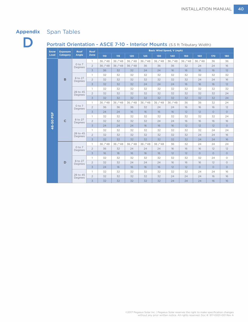
Span TablesAppendix
D Portrait Orientation - ASCE 7-10 - Interior Mounts (5.5 ft Tributary Width)
SnowLoad
Exposure Category
Roof Angle
Roof Zone
Basic Wind Speed, V (mph)
110 115 120 125 130 140 150 160 170 1804
6-5
0 P
SF
B
0 to 7 Degrees
1 36 /*48 36 /*48 36 /*48 36 /*48 36 /*48 36 /*48 36 /*48 36 /*48 36 36
2 36 /*48 36 /*48 36 /*48 36 36 36 32 24 24 16
3 36 32 32 24 24 16 16 16 16 12
8 to 27 Degrees
1 32 32 32 32 32 32 32 32 32 32
2 32 32 32 32 32 32 32 24 24 16
3 32 32 32 24 24 24 16 16 16 12
28 to 45 Degrees
1 32 32 32 32 32 32 32 32 32 32
2 32 32 32 32 32 32 32 32 32 24
3 32 32 32 32 32 32 32 32 32 24
C
0 to 7 Degrees
1 36 /*48 36 /*48 36 /*48 36 /*48 36 /*48 36 /*48 36 36 32 24
2 36 36 36 32 24 24 16 16 16 12
3 24 24 16 16 16 16 12 12 0 0
8 to 27 Degrees
1 32 32 32 32 32 32 32 32 32 24
2 32 32 32 32 24 24 16 16 16 16
3 24 24 24 16 16 16 12 12 12 0
28 to 45 Degrees
1 32 32 32 32 32 32 32 32 24 24
2 32 32 32 32 32 32 32 24 24 16
3 32 32 32 32 32 32 32 24 24 16
D
0 to 7 Degrees
1 36 /*48 36 /*48 36 /*48 36 /*48 36 /*48 36 32 24 24 24
2 36 32 24 24 24 16 16 16 12 12
3 16 16 16 16 16 12 12 0 0 0
8 to 27 Degrees
1 32 32 32 32 32 32 32 32 24 0
2 32 32 24 24 24 16 16 16 12 0
3 24 16 16 16 16 12 12 0 0 0
28 to 45 Degrees
1 32 32 32 32 32 32 32 24 24 16
2 32 32 32 32 32 24 24 24 16 16
3 32 32 32 32 32 24 24 24 16 16

INSTALLATION MANUAL
©2017 Pegasus Solar Inc. | Pegasus Solar reserves the right to make specification changeswithout any prior written notice. All rights reserved. Doc #: 917-0001-001 Rev A
41
Span TablesAppendix
D Landscape Orientation - ASCE 7-10 - Edge Mounts (1.65 ft Tributary Width)
SnowLoad
Exposure Category
Roof Angle
Roof Zone
Basic Wind Speed, V (mph)
110 115 120 125 130 140 150 160 170 1800
PS
F
B
0 to 7 Degrees
1 72 72 72 72 72 72 72 72 72 72
2 72 72 72 72 72 72 72 72 72 0
3 72 72 72 72 72 64 0 0 0 0
8 to 27 Degrees
1 72 72 72 72 72 72 72 72 72 72
2 72 72 72 72 72 72 72 72 72 64
3 72 72 72 72 72 72 0 0 0 0
28 to 45 Degrees
1 72 72 72 72 72 72 72 72 72 72
2 72 72 72 72 72 72 72 72 72 72
3 72 72 72 72 72 72 72 72 72 72
C
0 to 7 Degrees
1 72 72 72 72 72 72 72 72 72 72
2 72 72 72 72 72 72 0 0 0 0
3 72 72 64 0 0 0 0 0 0 0
8 to 27 Degrees
1 72 72 72 72 72 72 72 72 72 72
2 72 72 72 72 72 72 64 0 0 0
3 72 72 64 0 0 0 0 0 0 0
28 to 45 Degrees
1 72 72 72 72 72 72 72 72 72 72
2 72 72 72 72 72 72 72 72 72 64
3 72 72 72 72 72 72 72 72 72 64
D
0 to 7 Degrees
1 72 72 72 72 72 72 72 72 72 64
2 72 72 72 72 72 0 0 0 0 0
3 64 0 0 0 0 0 0 0 0 0
8 to 27 Degrees
1 72 72 72 72 72 72 72 72 72 72
2 72 72 72 72 72 64 0 0 0 0
3 64 0 0 0 0 0 0 0 0 0
28 to 45 Degrees
1 72 72 72 72 72 72 72 72 72 64
2 72 72 72 72 72 72 72 72 0 0
3 72 72 72 72 72 72 72 72 0 0
1-15
PS
F
B
0 to 7 Degrees
1 72 72 72 72 72 72 72 72 72 72
2 72 72 72 72 72 72 72 72 72 0
3 72 72 72 72 72 64 0 0 0 0
8 to 27 Degrees
1 72 72 72 72 72 72 72 72 72 72
2 72 72 72 72 72 72 72 72 72 64
3 72 72 72 72 72 72 0 0 0 0
28 to 45 Degrees
1 72 72 72 72 72 72 72 72 72 72
2 72 72 72 72 72 72 72 72 72 72
3 72 72 72 72 72 72 72 72 72 72
C
0 to 7 Degrees
1 72 72 72 72 72 72 72 72 72 72
2 72 72 72 72 72 72 0 0 0 0
3 72 72 64 0 0 0 0 0 0 0
8 to 27 Degrees
1 72 72 72 72 72 72 72 72 72 72
2 72 72 72 72 72 72 64 0 0 0
3 72 72 64 0 0 0 0 0 0 0
28 to 45 Degrees
1 72 72 72 72 72 72 72 72 72 72
2 72 72 72 72 72 72 72 72 72 64
3 72 72 72 72 72 72 72 72 72 64
D
0 to 7 Degrees
1 72 72 72 72 72 72 72 72 72 64
2 72 72 72 72 72 0 0 0 0 0
3 64 0 0 0 0 0 0 0 0 0
8 to 27 Degrees
1 72 72 72 72 72 72 72 72 72 72
2 72 72 72 72 72 64 0 0 0 0
3 64 0 0 0 0 0 0 0 0 0
28 to 45 Degrees
1 72 72 72 72 72 72 72 72 72 64
2 72 72 72 72 72 72 72 72 0 0
3 72 72 72 72 72 72 72 72 0 0

INSTALLATION MANUAL
©2017 Pegasus Solar Inc. | Pegasus Solar reserves the right to make specification changeswithout any prior written notice. All rights reserved. Doc #: 917-0001-001 Rev A
42
Span TablesAppendix
D Landscape Orientation - ASCE 7-10 - Edge Mounts (1.65 ft Tributary Width)
SnowLoad
Exposure Category
Roof Angle
Roof Zone
Basic Wind Speed, V (mph)
110 115 120 125 130 140 150 160 170 18016
-20
PS
F
B
0 to 7 Degrees
1 72 72 72 72 72 72 72 72 72 72
2 72 72 72 72 72 72 72 72 72 0
3 72 72 72 72 72 64 0 0 0 0
8 to 27 Degrees
1 72 72 72 72 72 72 72 72 72 72
2 72 72 72 72 72 72 72 72 72 64
3 72 72 72 72 72 72 0 0 0 0
28 to 45 Degrees
1 72 72 72 72 72 72 72 72 72 72
2 72 72 72 72 72 72 72 72 72 72
3 72 72 72 72 72 72 72 72 72 72
C
0 to 7 Degrees
1 72 72 72 72 72 72 72 72 72 72
2 72 72 72 72 72 72 0 0 0 0
3 72 72 64 0 0 0 0 0 0 0
8 to 27 Degrees
1 72 72 72 72 72 72 72 72 72 72
2 72 72 72 72 72 72 64 0 0 0
3 72 72 64 0 0 0 0 0 0 0
28 to 45 Degrees
1 72 72 72 72 72 72 72 72 72 72
2 72 72 72 72 72 72 72 72 72 64
3 72 72 72 72 72 72 72 72 72 64
D
0 to 7 Degrees
1 72 72 72 72 72 72 72 72 72 64
2 72 72 72 72 72 0 0 0 0 0
3 64 0 0 0 0 0 0 0 0 0
8 to 27 Degrees
1 72 72 72 72 72 72 72 72 72 72
2 72 72 72 72 72 64 0 0 0 0
3 64 0 0 0 0 0 0 0 0 0
28 to 45 Degrees
1 72 72 72 72 72 72 72 72 72 64
2 72 72 72 72 72 72 72 72 0 0
3 72 72 72 72 72 72 72 72 0 0
21-
25
PS
F
B
0 to 7 Degrees
1 72 72 72 72 72 72 72 72 72 72
2 72 72 72 72 72 72 72 72 72 0
3 72 72 72 72 72 64 0 0 0 0
8 to 27 Degrees
1 72 72 72 72 72 72 72 72 72 72
2 72 72 72 72 72 72 72 72 72 64
3 72 72 72 72 72 72 0 0 0 0
28 to 45 Degrees
1 72 72 72 72 72 72 72 72 72 72
2 72 72 72 72 72 72 72 72 72 72
3 72 72 72 72 72 72 72 72 72 72
C
0 to 7 Degrees
1 72 72 72 72 72 72 72 72 72 72
2 72 72 72 72 72 72 0 0 0 0
3 72 72 64 0 0 0 0 0 0 0
8 to 27 Degrees
1 72 72 72 72 72 72 72 72 72 72
2 72 72 72 72 72 72 64 0 0 0
3 72 72 64 0 0 0 0 0 0 0
28 to 45 Degrees
1 72 72 72 72 72 72 72 72 72 72
2 72 72 72 72 72 72 72 72 72 64
3 72 72 72 72 72 72 72 72 72 64
D
0 to 7 Degrees
1 72 72 72 72 72 72 72 72 72 64
2 72 72 72 72 72 0 0 0 0 0
3 64 0 0 0 0 0 0 0 0 0
8 to 27 Degrees
1 72 72 72 72 72 72 72 72 72 72
2 72 72 72 72 72 64 0 0 0 0
3 64 0 0 0 0 0 0 0 0 0
28 to 45 Degrees
1 72 72 72 72 72 72 72 72 72 64
2 72 72 72 72 72 72 72 72 0 0
3 72 72 72 72 72 72 72 72 0 0

INSTALLATION MANUAL
©2017 Pegasus Solar Inc. | Pegasus Solar reserves the right to make specification changeswithout any prior written notice. All rights reserved. Doc #: 917-0001-001 Rev A
43
Span TablesAppendix
D Landscape Orientation - ASCE 7-10 - Edge Mounts (1.65 ft Tributary Width)
SnowLoad
Exposure Category
Roof Angle
Roof Zone
Basic Wind Speed, V (mph)
110 115 120 125 130 140 150 160 170 1802
6-3
0 P
SF
B
0 to 7 Degrees
1 72 72 72 72 72 72 72 72 72 72
2 72 72 72 72 72 72 72 72 72 0
3 72 72 72 72 72 64 0 0 0 0
8 to 27 Degrees
1 72 72 72 72 72 72 72 72 72 72
2 72 72 72 72 72 72 72 72 72 64
3 72 72 72 72 72 72 0 0 0 0
28 to 45 Degrees
1 72 72 72 72 72 72 72 72 72 72
2 72 72 72 72 72 72 72 72 72 72
3 72 72 72 72 72 72 72 72 72 72
C
0 to 7 Degrees
1 72 72 72 72 72 72 72 72 72 72
2 72 72 72 72 72 72 0 0 0 0
3 72 72 64 0 0 0 0 0 0 0
8 to 27 Degrees
1 72 72 72 72 72 72 72 72 72 72
2 72 72 72 72 72 72 64 0 0 0
3 72 72 64 0 0 0 0 0 0 0
28 to 45 Degrees
1 72 72 72 72 72 72 72 72 72 72
2 72 72 72 72 72 72 72 72 72 64
3 72 72 72 72 72 72 72 72 72 64
D
0 to 7 Degrees
1 72 72 72 72 72 72 72 72 72 64
2 72 72 72 72 72 0 0 0 0 0
3 64 0 0 0 0 0 0 0 0 0
8 to 27 Degrees
1 72 72 72 72 72 72 72 72 72 72
2 72 72 72 72 72 64 0 0 0 0
3 64 0 0 0 0 0 0 0 0 0
28 to 45 Degrees
1 72 72 72 72 72 72 72 72 72 64
2 72 72 72 72 72 72 72 72 0 0
3 72 72 72 72 72 72 72 72 0 0
31-
35
PS
F
B
0 to 7 Degrees
1 72 72 72 72 72 72 72 72 72 72
2 72 72 72 72 72 72 72 72 72 0
3 72 72 72 72 72 64 0 0 0 0
8 to 27 Degrees
1 72 72 72 72 72 72 72 72 72 72
2 72 72 72 72 72 72 72 72 72 64
3 72 72 72 72 72 72 0 0 0 0
28 to 45 Degrees
1 72 72 72 72 72 72 72 72 72 72
2 72 72 72 72 72 72 72 72 72 72
3 72 72 72 72 72 72 72 72 72 72
C
0 to 7 Degrees
1 72 72 72 72 72 72 72 72 72 72
2 72 72 72 72 72 72 0 0 0 0
3 72 72 64 0 0 0 0 0 0 0
8 to 27 Degrees
1 72 72 72 72 72 72 72 72 72 72
2 72 72 72 72 72 72 64 0 0 0
3 72 72 64 0 0 0 0 0 0 0
28 to 45 Degrees
1 72 72 72 72 72 72 72 72 72 72
2 72 72 72 72 72 72 72 72 72 64
3 72 72 72 72 72 72 72 72 72 64
D
0 to 7 Degrees
1 72 72 72 72 72 72 72 72 72 64
2 72 72 72 72 72 0 0 0 0 0
3 64 0 0 0 0 0 0 0 0 0
8 to 27 Degrees
1 72 72 72 72 72 72 72 72 72 72
2 72 72 72 72 72 64 0 0 0 0
3 64 0 0 0 0 0 0 0 0 0
28 to 45 Degrees
1 72 72 72 72 72 72 72 72 72 64
2 72 72 72 72 72 72 72 72 0 0
3 72 72 72 72 72 72 72 72 0 0

INSTALLATION MANUAL
©2017 Pegasus Solar Inc. | Pegasus Solar reserves the right to make specification changeswithout any prior written notice. All rights reserved. Doc #: 917-0001-001 Rev A
44
Span TablesAppendix
D Landscape Orientation - ASCE 7-10 - Edge Mounts (1.65 ft Tributary Width)
SnowLoad
Exposure Category
Roof Angle
Roof Zone
Basic Wind Speed, V (mph)
110 115 120 125 130 140 150 160 170 1803
6-4
0 P
SF
B
0 to 7 Degrees
1 72 72 72 72 72 72 72 72 72 72
2 72 72 72 72 72 72 72 72 72 0
3 72 72 72 72 72 64 0 0 0 0
8 to 27 Degrees
1 72 72 72 72 72 72 72 72 72 72
2 72 72 72 72 72 72 72 72 72 64
3 72 72 72 72 72 72 0 0 0 0
28 to 45 Degrees
1 72 72 72 72 72 72 72 72 72 72
2 72 72 72 72 72 72 72 72 72 72
3 72 72 72 72 72 72 72 72 72 72
C
0 to 7 Degrees
1 72 72 72 72 72 72 72 72 72 72
2 72 72 72 72 72 72 0 0 0 0
3 72 72 64 0 0 0 0 0 0 0
8 to 27 Degrees
1 72 72 72 72 72 72 72 72 72 72
2 72 72 72 72 72 72 64 0 0 0
3 72 72 64 0 0 0 0 0 0 0
28 to 45 Degrees
1 72 72 72 72 72 72 72 72 72 72
2 72 72 72 72 72 72 72 72 72 64
3 72 72 72 72 72 72 72 72 72 64
D
0 to 7 Degrees
1 72 72 72 72 72 72 72 72 72 64
2 72 72 72 72 72 0 0 0 0 0
3 64 0 0 0 0 0 0 0 0 0
8 to 27 Degrees
1 72 72 72 72 72 72 72 72 72 72
2 72 72 72 72 72 64 0 0 0 0
3 64 0 0 0 0 0 0 0 0 0
28 to 45 Degrees
1 72 72 72 72 72 72 72 72 72 64
2 72 72 72 72 72 72 72 72 0 0
3 72 72 72 72 72 72 72 72 0 0
40
-50
PS
F
B
0 to 7 Degrees
1 72 72 72 72 72 72 72 72 72 72
2 72 72 72 72 72 72 72 72 72 0
3 72 72 72 72 72 64 0 0 0 0
8 to 27 Degrees
1 72 72 72 72 72 72 72 72 72 72
2 72 72 72 72 72 72 72 72 72 64
3 72 72 72 72 72 72 0 0 0 0
28 to 45 Degrees
1 72 72 72 72 72 72 72 72 72 72
2 72 72 72 72 72 72 72 72 72 72
3 72 72 72 72 72 72 72 72 72 72
C
0 to 7 Degrees
1 72 72 72 72 72 72 72 72 72 72
2 72 72 72 72 72 72 0 0 0 0
3 72 72 64 0 0 0 0 0 0 0
8 to 27 Degrees
1 72 72 72 72 72 72 72 72 64 64
2 72 72 72 72 72 72 64 0 0 0
3 72 72 64 0 0 0 0 0 0 0
28 to 45 Degrees
1 72 72 72 72 72 72 72 72 72 72
2 72 72 72 72 72 72 72 72 72 64
3 72 72 72 72 72 72 72 72 72 64
D
0 to 7 Degrees
1 72 72 72 72 72 72 72 72 72 64
2 72 72 72 72 72 0 0 0 0 0
3 64 0 0 0 0 0 0 0 0 0
8 to 27 Degrees
1 72 72 72 72 72 72 64 64 64 48
2 72 72 72 72 72 64 0 0 0 0
3 64 0 0 0 0 0 0 0 0 0
28 to 45 Degrees
1 72 72 72 72 72 72 72 72 64 64
2 72 72 72 72 72 72 72 72 0 0
3 72 72 72 72 72 72 72 72 0 0

INSTALLATION MANUAL
©2017 Pegasus Solar Inc. | Pegasus Solar reserves the right to make specification changeswithout any prior written notice. All rights reserved. Doc #: 917-0001-001 Rev A
45
Span TablesAppendix
D Landscape Orientation - ASCE 7-10 - Edge Mounts (1.65 ft Tributary Width)
SnowLoad
Exposure Category
Roof Angle
Roof Zone
Basic Wind Speed, V (mph)
110 115 120 125 130 140 150 160 170 1805
1-70
PS
F
B
0 to 7 Degrees
1 48 48 48 48 48 48 48 48 48 48
2 48 48 48 48 48 48 48 48 48 0
3 48 48 48 48 48 48 0 0 0 0
8 to 27 Degrees
1 48 48 48 48 48 48 48 48 48 48
2 48 48 48 48 48 48 48 48 48 48
3 48 48 48 48 48 48 0 0 0 0
28 to 45 Degrees
1 72 72 72 72 72 72 72 72 72 72
2 72 72 72 72 72 72 72 72 72 72
3 72 72 72 72 72 72 72 72 72 72
C
0 to 7 Degrees
1 48 48 48 48 48 48 48 48 48 48
2 48 48 48 48 48 48 0 0 0 0
3 48 48 48 0 0 0 0 0 0 0
8 to 27 Degrees
1 48 48 48 48 48 48 48 48 48 48
2 48 48 48 48 48 48 48 0 0 0
3 48 48 48 0 0 0 0 0 0 0
28 to 45 Degrees
1 72 72 72 72 72 72 72 72 64 48
2 72 72 72 72 72 72 72 72 64 48
3 72 72 72 72 72 72 72 72 64 48
D
0 to 7 Degrees
1 48 48 48 48 48 48 48 48 48 48
2 48 48 48 48 48 0 0 0 0 0
3 48 0 0 0 0 0 0 0 0 0
8 to 27 Degrees
1 48 48 48 48 48 48 48 48 48 48
2 48 48 48 48 48 48 0 0 0 0
3 48 0 0 0 0 0 0 0 0 0
28 to 45 Degrees
1 72 72 72 72 72 72 72 64 48 48
2 72 72 72 72 72 72 72 64 0 0
3 72 72 72 72 72 72 72 64 0 0
71-
90
PS
F
B
0 to 7 Degrees
1 48 48 48 48 48 48 48 48 48 48
2 48 48 48 48 48 48 48 48 48 0
3 48 48 48 48 48 48 0 0 0 0
8 to 27 Degrees
1 48 48 48 48 48 48 48 48 48 48
2 48 48 48 48 48 48 48 48 48 48
3 48 48 48 48 48 48 0 0 0 0
28 to 45 Degrees
1 64 64 64 64 64 64 64 64 64 64
2 64 64 64 64 64 64 64 64 64 64
3 64 64 64 64 64 64 64 64 64 64
C
0 to 7 Degrees
1 48 48 48 48 48 48 48 48 48 48
2 48 48 48 48 48 48 0 0 0 0
3 48 48 48 0 0 0 0 0 0 0
8 to 27 Degrees
1 48 48 48 48 48 48 48 48 48 48
2 48 48 48 48 48 48 48 0 0 0
3 48 48 48 0 0 0 0 0 0 0
28 to 45 Degrees
1 64 64 64 64 64 64 64 48 48 48
2 64 64 64 64 64 64 64 48 48 48
3 64 64 64 64 64 64 64 48 48 48
D
0 to 7 Degrees
1 48 48 48 48 48 48 48 48 48 48
2 48 48 48 48 48 0 0 0 0 0
3 48 0 0 0 0 0 0 0 0 0
8 to 27 Degrees
1 48 48 48 48 48 48 48 48 48 48
2 48 48 48 48 48 48 0 0 0 0
3 48 0 0 0 0 0 0 0 0 0
28 to 45 Degrees
1 64 64 64 64 64 64 48 48 48 48
2 64 64 64 64 64 64 48 48 0 0
3 64 64 64 64 64 64 48 48 0 0

INSTALLATION MANUAL
©2017 Pegasus Solar Inc. | Pegasus Solar reserves the right to make specification changeswithout any prior written notice. All rights reserved. Doc #: 917-0001-001 Rev A
46
Span TablesAppendix
D Portrait Orientation - ASCE 7-10 - Edge Mounts (2.75 ft Tributary Width)
SnowLoad
Exposure Category
Roof Angle
Roof Zone
Basic Wind Speed, V (mph)
110 115 120 125 130 140 150 160 170 1800
PS
F
B
0 to 7 Degrees
1 48 /*72 48 /*72 48 /*72 48 /*72 48 /*72 48 /*72 48 /*72 48 /*72 48 /*72 48 /*72
2 48 /*72 48 /*72 48 /*72 48 /*72 48 /*72 48 /*72 48 /*64 48 48 36
3 48 /*72 48 /*64 48 /*64 48 /*60 48 36 36 36 32 24
8 to 27 Degrees
1 48 /*72 48 /*72 48 /*72 48 /*72 48 /*72 48 /*72 48 /*72 48 /*72 48 /*72 48 /*72
2 48 /*72 48 /*72 48 /*72 48 /*72 48 /*72 48 /*72 48 /*64 48 48 36
3 48 /*72 48 /*72 48 /*64 48 /*60 48 48 36 36 32 24
28 to 45 Degrees
1 48 /*72 48 /*72 48 /*72 48 /*72 48 /*72 48 /*72 48 /*72 48 /*72 48 /*72 48 /*72
2 48 /*72 48 /*72 48 /*72 48 /*72 48 /*72 48 /*72 48 /*72 48 /*72 48 /*64 48 /*60
3 48 /*72 48 /*72 48 /*72 48 /*72 48 /*72 48 /*72 48 /*72 48 /*72 48 /*64 48 /*60
C
0 to 7 Degrees
1 48 /*72 48 /*72 48 /*72 48 /*72 48 /*72 48 /*72 48 /*72 48 /*72 48 /*64 48
2 48 /*72 48 /*72 48 /*72 48 /*64 48 /*60 48 36 36 32 24
3 48 48 36 36 36 32 24 24 16 16
8 to 27 Degrees
1 48 /*72 48 /*72 48 /*72 48 /*72 48 /*72 48 /*72 48 /*72 48 /*72 48 /*64 48 /*60
2 48 /*72 48 /*72 48 /*72 48 /*64 48 /*60 48 36 36 36 32
3 48 48 48 36 36 32 24 24 24 16
28 to 45 Degrees
1 48 /*72 48 /*72 48 /*72 48 /*72 48 /*72 48 /*72 48 /*72 48 /*64 48 /*60 48
2 48 /*72 48 /*72 48 /*72 48 /*72 48 /*72 48 /*72 48 /*64 48 48 36
3 48 /*72 48 /*72 48 /*72 48 /*72 48 /*72 48 /*72 48 /*64 48 48 36
D
0 to 7 Degrees
1 48 /*72 48 /*72 48 /*72 48 /*72 48 /*72 48 /*72 48 /*64 48 /*60 48 48
2 48 /*72 48 /*64 48 /*60 48 48 36 36 32 24 24
3 36 36 36 32 32 24 24 16 16 16
8 to 27 Degrees
1 48 /*72 48 /*72 48 /*72 48 /*72 48 /*72 48 /*72 48 /*72 48 /*64 48 48
2 48 /*72 48 /*64 48 /*60 48 48 36 36 32 24 24
3 48 36 36 36 32 24 24 16 16 16
28 to 45 Degrees
1 48 /*72 48 /*72 48 /*72 48 /*72 48 /*72 48 /*72 48 /*64 48 48 36
2 48 /*72 48 /*72 48 /*72 48 /*72 48 /*72 48 /*60 48 48 36 36
3 48 /*72 48 /*72 48 /*72 48 /*72 48 /*72 48 /*60 48 48 36 36
1-15
PS
F
B
0 to 7 Degrees
1 48 /*72 48 /*72 48 /*72 48 /*72 48 /*72 48 /*72 48 /*72 48 /*72 48 /*72 48 /*72
2 48 /*72 48 /*72 48 /*72 48 /*72 48 /*72 48 /*72 48 /*64 48 48 36
3 48 /*72 48 /*64 48 /*64 48 /*60 48 36 36 36 32 24
8 to 27 Degrees
1 48 /*72 48 /*72 48 /*72 48 /*72 48 /*72 48 /*72 48 /*72 48 /*72 48 /*72 48 /*72
2 48 /*72 48 /*72 48 /*72 48 /*72 48 /*72 48 /*72 48 /*64 48 48 36
3 48 /*72 48 /*72 48 /*64 48 /*60 48 48 36 36 32 24
28 to 45 Degrees
1 48 /*72 48 /*72 48 /*72 48 /*72 48 /*72 48 /*72 48 /*72 48 /*72 48 /*72 48 /*72
2 48 /*72 48 /*72 48 /*72 48 /*72 48 /*72 48 /*72 48 /*72 48 /*72 48 /*64 48 /*60
3 48 /*72 48 /*72 48 /*72 48 /*72 48 /*72 48 /*72 48 /*72 48 /*72 48 /*64 48 /*60
C
0 to 7 Degrees
1 48 /*72 48 /*72 48 /*72 48 /*72 48 /*72 48 /*72 48 /*72 48 /*72 48 /*64 48
2 48 /*72 48 /*72 48 /*72 48 /*64 48 /*60 48 36 36 32 24
3 48 48 36 36 36 32 24 24 16 16
8 to 27 Degrees
1 48 /*72 48 /*72 48 /*72 48 /*72 48 /*72 48 /*72 48 /*72 48 /*72 48 /*64 48 /*60
2 48 /*72 48 /*72 48 /*72 48 /*64 48 /*60 48 36 36 36 32
3 48 48 48 36 36 32 24 24 24 16
28 to 45 Degrees
1 48 /*72 48 /*72 48 /*72 48 /*72 48 /*72 48 /*72 48 /*72 48 /*64 48 /*60 48
2 48 /*72 48 /*72 48 /*72 48 /*72 48 /*72 48 /*72 48 /*64 48 48 36
3 48 /*72 48 /*72 48 /*72 48 /*72 48 /*72 48 /*72 48 /*64 48 48 36
D
0 to 7 Degrees
1 48 /*72 48 /*72 48 /*72 48 /*72 48 /*72 48 /*72 48 /*64 48 /*60 48 48
2 48 /*72 48 /*64 48 /*60 48 48 36 36 32 24 24
3 36 36 36 32 32 24 24 16 16 16
8 to 27 Degrees
1 48 /*72 48 /*72 48 /*72 48 /*72 48 /*72 48 /*72 48 /*72 48 /*64 48 48
2 48 /*72 48 /*64 48 /*60 48 48 36 36 32 24 24
3 48 36 36 36 32 24 24 16 16 16
28 to 45 Degrees
1 48 /*72 48 /*72 48 /*72 48 /*72 48 /*72 48 /*72 48 /*64 48 48 36
2 48 /*72 48 /*72 48 /*72 48 /*72 48 /*72 48 /*60 48 48 36 36
3 48 /*72 48 /*72 48 /*72 48 /*72 48 /*72 48 /*60 48 48 36 36

INSTALLATION MANUAL
©2017 Pegasus Solar Inc. | Pegasus Solar reserves the right to make specification changeswithout any prior written notice. All rights reserved. Doc #: 917-0001-001 Rev A
47
Span TablesAppendix
D Portrait Orientation - ASCE 7-10 - Edge Mounts (2.75 ft Tributary Width)
SnowLoad
Exposure Category
Roof Angle
Roof Zone
Basic Wind Speed, V (mph)
110 115 120 125 130 140 150 160 170 18016
-20
PS
F
B
0 to 7 Degrees
1 48 /*72 48 /*72 48 /*72 48 /*72 48 /*72 48 /*72 48 /*72 48 /*72 48 /*72 48 /*72
2 48 /*72 48 /*72 48 /*72 48 /*72 48 /*72 48 /*72 48 /*64 48 48 36
3 48 /*72 48 /*64 48 /*64 48 /*60 48 36 36 36 32 24
8 to 27 Degrees
1 48 /*72 48 /*72 48 /*72 48 /*72 48 /*72 48 /*72 48 /*72 48 /*72 48 /*72 48 /*72
2 48 /*72 48 /*72 48 /*72 48 /*72 48 /*72 48 /*72 48 /*64 48 48 36
3 48 /*72 48 /*72 48 /*64 48 /*60 48 48 36 36 32 24
28 to 45 Degrees
1 48 /*72 48 /*72 48 /*72 48 /*72 48 /*72 48 /*72 48 /*72 48 /*72 48 /*72 48 /*72
2 48 /*72 48 /*72 48 /*72 48 /*72 48 /*72 48 /*72 48 /*72 48 /*72 48 /*64 48 /*60
3 48 /*72 48 /*72 48 /*72 48 /*72 48 /*72 48 /*72 48 /*72 48 /*72 48 /*64 48 /*60
C
0 to 7 Degrees
1 48 /*72 48 /*72 48 /*72 48 /*72 48 /*72 48 /*72 48 /*72 48 /*72 48 /*64 48
2 48 /*72 48 /*72 48 /*72 48 /*64 48 /*60 48 36 36 32 24
3 48 48 36 36 36 32 24 24 16 16
8 to 27 Degrees
1 48 /*72 48 /*72 48 /*72 48 /*72 48 /*72 48 /*72 48 /*72 48 /*72 48 /*64 48 /*60
2 48 /*72 48 /*72 48 /*72 48 /*64 48 /*60 48 36 36 36 32
3 48 48 48 36 36 32 24 24 24 16
28 to 45 Degrees
1 48 /*72 48 /*72 48 /*72 48 /*72 48 /*72 48 /*72 48 /*72 48 /*64 48 /*60 48
2 48 /*72 48 /*72 48 /*72 48 /*72 48 /*72 48 /*72 48 /*64 48 48 36
3 48 /*72 48 /*72 48 /*72 48 /*72 48 /*72 48 /*72 48 /*64 48 48 36
D
0 to 7 Degrees
1 48 /*72 48 /*72 48 /*72 48 /*72 48 /*72 48 /*72 48 /*64 48 /*60 48 48
2 48 /*72 48 /*64 48 /*60 48 48 36 36 32 24 24
3 36 36 36 32 32 24 24 16 16 16
8 to 27 Degrees
1 48 /*72 48 /*72 48 /*72 48 /*72 48 /*72 48 /*72 48 /*72 48 /*64 48 48
2 48 /*72 48 /*64 48 /*60 48 48 36 36 32 24 24
3 48 36 36 36 32 24 24 16 16 16
28 to 45 Degrees
1 48 /*72 48 /*72 48 /*72 48 /*72 48 /*72 48 /*72 48 /*64 48 48 36
2 48 /*72 48 /*72 48 /*72 48 /*72 48 /*72 48 /*60 48 48 36 36
3 48 /*72 48 /*72 48 /*72 48 /*72 48 /*72 48 /*60 48 48 36 36
21-
25
PS
F
B
0 to 7 Degrees
1 48 /*72 48 /*72 48 /*72 48 /*72 48 /*72 48 /*72 48 /*72 48 /*72 48 /*72 48 /*72
2 48 /*72 48 /*72 48 /*72 48 /*72 48 /*72 48 /*72 48 /*64 48 48 36
3 48 /*72 48 /*64 48 /*64 48 /*60 48 36 36 36 32 24
8 to 27 Degrees
1 48 /*72 48 /*72 48 /*72 48 /*72 48 /*72 48 /*72 48 /*72 48 /*72 48 /*72 48 /*72
2 48 /*72 48 /*72 48 /*72 48 /*72 48 /*72 48 /*72 48 /*64 48 48 36
3 48 /*72 48 /*72 48 /*64 48 /*60 48 48 36 36 32 24
28 to 45 Degrees
1 48 /*72 48 /*72 48 /*72 48 /*72 48 /*72 48 /*72 48 /*72 48 /*72 48 /*72 48 /*72
2 48 /*72 48 /*72 48 /*72 48 /*72 48 /*72 48 /*72 48 /*72 48 /*72 48 /*64 48 /*60
3 48 /*72 48 /*72 48 /*72 48 /*72 48 /*72 48 /*72 48 /*72 48 /*72 48 /*64 48 /*60
C
0 to 7 Degrees
1 48 /*72 48 /*72 48 /*72 48 /*72 48 /*72 48 /*72 48 /*72 48 /*72 48 /*64 48
2 48 /*72 48 /*72 48 /*72 48 /*64 48 /*60 48 36 36 32 24
3 48 48 36 36 36 32 24 24 16 16
8 to 27 Degrees
1 48 /*72 48 /*72 48 /*72 48 /*72 48 /*72 48 /*72 48 /*72 48 /*72 48 /*64 48 /*60
2 48 /*72 48 /*72 48 /*72 48 /*64 48 /*60 48 36 36 36 32
3 48 48 48 36 36 32 24 24 24 16
28 to 45 Degrees
1 48 /*72 48 /*72 48 /*72 48 /*72 48 /*72 48 /*72 48 /*72 48 /*64 48 /*60 48
2 48 /*72 48 /*72 48 /*72 48 /*72 48 /*72 48 /*72 48 /*64 48 48 36
3 48 /*72 48 /*72 48 /*72 48 /*72 48 /*72 48 /*72 48 /*64 48 48 36
D
0 to 7 Degrees
1 48 /*72 48 /*72 48 /*72 48 /*72 48 /*72 48 /*72 48 /*64 48 /*60 48 48
2 48 /*72 48 /*64 48 /*60 48 48 36 36 32 24 24
3 36 36 36 32 32 24 24 16 16 16
8 to 27 Degrees
1 48 /*72 48 /*72 48 /*72 48 /*72 48 /*72 48 /*72 48 /*72 48 /*64 48 48
2 48 /*72 48 /*64 48 /*60 48 48 36 36 32 24 24
3 48 36 36 36 32 24 24 16 16 16
28 to 45 Degrees
1 48 /*72 48 /*72 48 /*72 48 /*72 48 /*72 48 /*72 48 /*64 48 48 36
2 48 /*72 48 /*72 48 /*72 48 /*72 48 /*72 48 /*60 48 48 36 36
3 48 /*72 48 /*72 48 /*72 48 /*72 48 /*72 48 /*60 48 48 36 36

INSTALLATION MANUAL
©2017 Pegasus Solar Inc. | Pegasus Solar reserves the right to make specification changeswithout any prior written notice. All rights reserved. Doc #: 917-0001-001 Rev A
48
Span TablesAppendix
D Portrait Orientation - ASCE 7-10 - Edge Mounts (2.75 ft Tributary Width)
SnowLoad
Exposure Category
Roof Angle
Roof Zone
Basic Wind Speed, V (mph)
110 115 120 125 130 140 150 160 170 1802
6-3
0 P
SF
B
0 to 7 Degrees
1 48 /*72 48 /*72 48 /*72 48 /*72 48 /*72 48 /*72 48 /*72 48 /*72 48 /*72 48 /*72
2 48 /*72 48 /*72 48 /*72 48 /*72 48 /*72 48 /*72 48 /*64 48 48 36
3 48 /*72 48 /*64 48 /*64 48 /*60 48 36 36 36 32 24
8 to 27 Degrees
1 48 /*72 48 /*72 48 /*72 48 /*72 48 /*72 48 /*72 48 /*72 48 /*72 48 /*72 48 /*72
2 48 /*72 48 /*72 48 /*72 48 /*72 48 /*72 48 /*72 48 /*64 48 48 36
3 48 /*72 48 /*72 48 /*64 48 /*60 48 48 36 36 32 24
28 to 45 Degrees
1 48 /*72 48 /*72 48 /*72 48 /*72 48 /*72 48 /*72 48 /*72 48 /*72 48 /*72 48 /*72
2 48 /*72 48 /*72 48 /*72 48 /*72 48 /*72 48 /*72 48 /*72 48 /*72 48 /*64 48 /*60
3 48 /*72 48 /*72 48 /*72 48 /*72 48 /*72 48 /*72 48 /*72 48 /*72 48 /*64 48 /*60
C
0 to 7 Degrees
1 48 /*72 48 /*72 48 /*72 48 /*72 48 /*72 48 /*72 48 /*72 48 /*72 48 /*64 48
2 48 /*72 48 /*72 48 /*72 48 /*64 48 /*60 48 36 36 32 24
3 48 48 36 36 36 32 24 24 16 16
8 to 27 Degrees
1 48 /*72 48 /*72 48 /*72 48 /*72 48 /*72 48 /*72 48 /*72 48 /*72 48 /*64 48 /*60
2 48 /*72 48 /*72 48 /*72 48 /*64 48 /*60 48 36 36 36 32
3 48 48 48 36 36 32 24 24 24 16
28 to 45 Degrees
1 48 /*72 48 /*72 48 /*72 48 /*72 48 /*72 48 /*72 48 /*72 48 /*64 48 /*60 48
2 48 /*72 48 /*72 48 /*72 48 /*72 48 /*72 48 /*72 48 /*64 48 48 36
3 48 /*72 48 /*72 48 /*72 48 /*72 48 /*72 48 /*72 48 /*64 48 48 36
D
0 to 7 Degrees
1 48 /*72 48 /*72 48 /*72 48 /*72 48 /*72 48 /*72 48 /*64 48 /*60 48 48
2 48 /*72 48 /*64 48 /*60 48 48 36 36 32 24 24
3 36 36 36 32 32 24 24 16 16 16
8 to 27 Degrees
1 48 /*72 48 /*72 48 /*72 48 /*72 48 /*72 48 /*72 48 /*72 48 /*64 48 48
2 48 /*72 48 /*64 48 /*60 48 48 36 36 32 24 24
3 48 36 36 36 32 24 24 16 16 16
28 to 45 Degrees
1 48 /*72 48 /*72 48 /*72 48 /*72 48 /*72 48 /*72 48 /*64 48 48 36
2 48 /*72 48 /*72 48 /*72 48 /*72 48 /*72 48 /*60 48 48 36 36
3 48 /*72 48 /*72 48 /*72 48 /*72 48 /*72 48 /*60 48 48 36 36
31-
35
PS
F
B
0 to 7 Degrees
1 48 /*72 48 /*72 48 /*72 48 /*72 48 /*72 48 /*72 48 /*72 48 /*72 48 /*72 48 /*72
2 48 /*72 48 /*72 48 /*72 48 /*72 48 /*72 48 /*72 48 /*64 48 48 36
3 48 /*72 48 /*64 48 /*64 48 /*60 48 36 36 36 32 24
8 to 27 Degrees
1 48 /*72 48 /*72 48 /*72 48 /*72 48 /*72 48 /*72 48 /*72 48 /*72 48 /*72 48 /*72
2 48 /*72 48 /*72 48 /*72 48 /*72 48 /*72 48 /*72 48 /*64 48 48 36
3 48 /*72 48 /*72 48 /*64 48 /*60 48 48 36 36 32 24
28 to 45 Degrees
1 48 /*72 48 /*72 48 /*72 48 /*72 48 /*72 48 /*72 48 /*72 48 /*72 48 /*72 48 /*72
2 48 /*72 48 /*72 48 /*72 48 /*72 48 /*72 48 /*72 48 /*72 48 /*72 48 /*64 48 /*60
3 48 /*72 48 /*72 48 /*72 48 /*72 48 /*72 48 /*72 48 /*72 48 /*72 48 /*64 48 /*60
C
0 to 7 Degrees
1 48 /*72 48 /*72 48 /*72 48 /*72 48 /*72 48 /*72 48 /*72 48 /*72 48 /*64 48
2 48 /*72 48 /*72 48 /*72 48 /*64 48 /*60 48 36 36 32 24
3 48 48 36 36 36 32 24 24 16 16
8 to 27 Degrees
1 48 /*72 48 /*72 48 /*72 48 /*72 48 /*72 48 /*72 48 /*72 48 /*72 48 /*64 48 /*60
2 48 /*72 48 /*72 48 /*72 48 /*64 48 /*60 48 36 36 36 32
3 48 48 48 36 36 32 24 24 24 16
28 to 45 Degrees
1 48 /*72 48 /*72 48 /*72 48 /*72 48 /*72 48 /*72 48 /*72 48 /*64 48 /*60 48
2 48 /*72 48 /*72 48 /*72 48 /*72 48 /*72 48 /*72 48 /*64 48 48 36
3 48 /*72 48 /*72 48 /*72 48 /*72 48 /*72 48 /*72 48 /*64 48 48 36
D
0 to 7 Degrees
1 48 /*72 48 /*72 48 /*72 48 /*72 48 /*72 48 /*72 48 /*64 48 /*60 48 48
2 48 /*72 48 /*64 48 /*60 48 48 36 36 32 24 24
3 36 36 36 32 32 24 24 16 16 16
8 to 27 Degrees
1 48 /*72 48 /*72 48 /*72 48 /*72 48 /*72 48 /*72 48 /*72 48 /*64 48 48
2 48 /*72 48 /*64 48 /*60 48 48 36 36 32 24 24
3 48 36 36 36 32 24 24 16 16 16
28 to 45 Degrees
1 48 /*72 48 /*72 48 /*72 48 /*72 48 /*72 48 /*72 48 /*64 48 48 36
2 48 /*72 48 /*72 48 /*72 48 /*72 48 /*72 48 /*60 48 48 36 36
3 48 /*72 48 /*72 48 /*72 48 /*72 48 /*72 48 /*60 48 48 36 36

INSTALLATION MANUAL
©2017 Pegasus Solar Inc. | Pegasus Solar reserves the right to make specification changeswithout any prior written notice. All rights reserved. Doc #: 917-0001-001 Rev A
49
Span TablesAppendix
D Portrait Orientation - ASCE 7-10 - Edge Mounts (2.75 ft Tributary Width)
SnowLoad
Exposure Category
Roof Angle
Roof Zone
Basic Wind Speed, V (mph)
110 115 120 125 130 140 150 160 170 1803
6-4
0 P
SF
B
0 to 7 Degrees
1 48 /*72 48 /*72 48 /*72 48 /*72 48 /*72 48 /*72 48 /*72 48 /*72 48 /*72 48 /*72
2 48 /*72 48 /*72 48 /*72 48 /*72 48 /*72 48 /*72 48 /*64 48 48 36
3 48 /*72 48 /*64 48 /*64 48 /*60 48 36 36 36 32 24
8 to 27 Degrees
1 48 /*72 48 /*72 48 /*72 48 /*72 48 /*72 48 /*72 48 /*72 48 /*72 48 /*72 48 /*72
2 48 /*72 48 /*72 48 /*72 48 /*72 48 /*72 48 /*72 48 /*64 48 48 36
3 48 /*72 48 /*72 48 /*64 48 /*60 48 48 36 36 32 24
28 to 45 Degrees
1 48 /*72 48 /*72 48 /*72 48 /*72 48 /*72 48 /*72 48 /*72 48 /*72 48 /*72 48 /*72
2 48 /*72 48 /*72 48 /*72 48 /*72 48 /*72 48 /*72 48 /*72 48 /*72 48 /*64 48 /*60
3 48 /*72 48 /*72 48 /*72 48 /*72 48 /*72 48 /*72 48 /*72 48 /*72 48 /*64 48 /*60
C
0 to 7 Degrees
1 48 /*72 48 /*72 48 /*72 48 /*72 48 /*72 48 /*72 48 /*72 48 /*72 48 /*64 48
2 48 /*72 48 /*72 48 /*72 48 /*64 48 /*60 48 36 36 32 24
3 48 48 36 36 36 32 24 24 16 16
8 to 27 Degrees
1 48 /*72 48 /*72 48 /*72 48 /*72 48 /*72 48 /*72 48 /*72 48 /*72 48 /*64 48 /*60
2 48 /*72 48 /*72 48 /*72 48 /*64 48 /*60 48 36 36 36 32
3 48 48 48 36 36 32 24 24 24 16
28 to 45 Degrees
1 48 /*72 48 /*72 48 /*72 48 /*72 48 /*72 48 /*72 48 /*72 48 /*64 48 /*60 48
2 48 /*72 48 /*72 48 /*72 48 /*72 48 /*72 48 /*72 48 /*64 48 48 36
3 48 /*72 48 /*72 48 /*72 48 /*72 48 /*72 48 /*72 48 /*64 48 48 36
D
0 to 7 Degrees
1 48 /*72 48 /*72 48 /*72 48 /*72 48 /*72 48 /*72 48 /*64 48 /*60 48 48
2 48 /*72 48 /*64 48 /*60 48 48 36 36 32 24 24
3 36 36 36 32 32 24 24 16 16 16
8 to 27 Degrees
1 48 /*72 48 /*72 48 /*72 48 /*72 48 /*72 48 /*72 48 /*72 48 /*64 48 48
2 48 /*72 48 /*64 48 /*60 48 48 36 36 32 24 24
3 48 36 36 36 32 24 24 16 16 16
28 to 45 Degrees
1 48 /*72 48 /*72 48 /*72 48 /*72 48 /*72 48 /*72 48 /*64 48 48 36
2 48 /*72 48 /*72 48 /*72 48 /*72 48 /*72 48 /*60 48 48 36 36
3 48 /*72 48 /*72 48 /*72 48 /*72 48 /*72 48 /*60 48 48 36 36
41-
45
PS
F
B
0 to 7 Degrees
1 48 /*72 48 /*72 48 /*72 48 /*72 48 /*72 48 /*72 48 /*72 48 /*72 48 /*72 48 /*72
2 48 /*72 48 /*72 48 /*72 48 /*72 48 /*72 48 /*72 48 /*64 48 48 36
3 48 /*72 48 /*64 48 /*64 48 /*60 48 36 36 36 32 24
8 to 27 Degrees
1 48 /*72 48 /*72 48 /*72 48 /*72 48 /*72 48 /*72 48 /*72 48 /*72 48 /*72 48 /*72
2 48 /*72 48 /*72 48 /*72 48 /*72 48 /*72 48 /*72 48 /*64 48 48 36
3 48 /*72 48 /*72 48 /*64 48 /*60 48 48 36 36 32 24
28 to 45 Degrees
1 48 /*72 48 /*72 48 /*72 48 /*72 48 /*72 48 /*72 48 /*72 48 /*72 48 /*72 48 /*72
2 48 /*72 48 /*72 48 /*72 48 /*72 48 /*72 48 /*72 48 /*72 48 /*72 48 /*64 48 /*60
3 48 /*72 48 /*72 48 /*72 48 /*72 48 /*72 48 /*72 48 /*72 48 /*72 48 /*64 48 /*60
C
0 to 7 Degrees
1 48 /*72 48 /*72 48 /*72 48 /*72 48 /*72 48 /*72 48 /*72 48 /*72 48 /*64 48
2 48 /*72 48 /*72 48 /*72 48 /*64 48 /*60 48 36 36 32 24
3 48 48 36 36 36 32 24 24 16 16
8 to 27 Degrees
1 48 /*72 48 /*72 48 /*72 48 /*72 48 /*72 48 /*72 48 /*72 48 /*72 48 /*64 48 /*60
2 48 /*72 48 /*72 48 /*72 48 /*64 48 /*60 48 36 36 36 32
3 48 48 48 36 36 32 24 24 24 16
28 to 45 Degrees
1 48 /*72 48 /*72 48 /*72 48 /*72 48 /*72 48 /*72 48 /*72 48 /*64 48 /*60 48
2 48 /*72 48 /*72 48 /*72 48 /*72 48 /*72 48 /*72 48 /*64 48 48 36
3 48 /*72 48 /*72 48 /*72 48 /*72 48 /*72 48 /*72 48 /*64 48 48 36
D
0 to 7 Degrees
1 48 /*72 48 /*72 48 /*72 48 /*72 48 /*72 48 /*72 48 /*64 48 /*60 48 48
2 48 /*72 48 /*64 48 /*60 48 48 36 36 32 24 24
3 36 36 36 32 32 24 24 16 16 16
8 to 27 Degrees
1 48 /*72 48 /*72 48 /*72 48 /*72 48 /*72 48 /*72 48 /*72 48 /*64 48 48
2 48 /*72 48 /*64 48 /*60 48 48 36 36 32 24 24
3 48 36 36 36 32 24 24 16 16 16
28 to 45 Degrees
1 48 /*72 48 /*72 48 /*72 48 /*72 48 /*72 48 /*72 48 /*64 48 48 36
2 48 /*72 48 /*72 48 /*72 48 /*72 48 /*72 48 /*60 48 48 36 36
3 48 /*72 48 /*72 48 /*72 48 /*72 48 /*72 48 /*60 48 48 36 36

INSTALLATION MANUAL
©2017 Pegasus Solar Inc. | Pegasus Solar reserves the right to make specification changeswithout any prior written notice. All rights reserved. Doc #: 917-0001-001 Rev A
50
Span TablesAppendix
D Portrait Orientation - ASCE 7-10 - Edge Mounts (2.75 ft Tributary Width)
SnowLoad
Exposure Category
Roof Angle
Roof Zone
Basic Wind Speed, V (mph)
110 115 120 125 130 140 150 160 170 1804
6-5
0 P
SF
B
0 to 7 Degrees
1 48 /*72 48 /*72 48 /*72 48 /*72 48 /*72 48 /*72 48 /*72 48 /*72 48 /*72 48 /*72
2 48 /*72 48 /*72 48 /*72 48 /*72 48 /*72 48 /*72 48 /*64 48 48 36
3 48 /*72 48 /*64 48 /*64 48 /*60 48 36 36 36 32 24
8 to 27 Degrees
1 48 /*64 48 /*64 48 /*64 48 /*64 48 /*64 48 /*64 48 /*64 48 /*64 48 /*64 48 /*64
2 48 /*64 48 /*64 48 /*64 48 /*64 48 /*64 48 /*64 48 /*64 48 48 36
3 48 /*64 48 /*64 48 /*64 48 /*60 48 48 36 36 32 24
28 to 45 Degrees
1 48 /*64 48 /*64 48 /*64 48 /*64 48 /*64 48 /*64 48 /*64 48 /*64 48 /*64 48 /*64
2 48 /*64 48 /*64 48 /*64 48 /*64 48 /*64 48 /*64 48 /*64 48 /*64 48 /*64 48 /*60
3 48 /*64 48 /*64 48 /*64 48 /*64 48 /*64 48 /*64 48 /*64 48 /*64 48 /*64 48 /*60
C
0 to 7 Degrees
1 48 /*72 48 /*72 48 /*72 48 /*72 48 /*72 48 /*72 48 /*72 48 /*72 48 /*64 48
2 48 /*72 48 /*72 48 /*72 48 /*64 48 /*60 48 36 36 32 24
3 48 48 36 36 36 32 24 24 16 16
8 to 27 Degrees
1 48 /*64 48 /*64 48 /*64 48 /*64 48 /*64 48 /*64 48 /*64 48 /*64 48 /*64 48 /*60
2 48 /*64 48 /*64 48 /*64 48 /*64 48 /*60 48 36 36 36 32
3 48 48 48 36 36 32 24 24 24 16
28 to 45 Degrees
1 48 /*64 48 /*64 48 /*64 48 /*64 48 /*64 48 /*64 48 /*64 48 /*64 48 /*60 48
2 48 /*64 48 /*64 48 /*64 48 /*64 48 /*64 48 /*64 48 /*64 48 48 36
3 48 /*64 48 /*64 48 /*64 48 /*64 48 /*64 48 /*64 48 /*64 48 48 36
D
0 to 7 Degrees
1 48 /*72 48 /*72 48 /*72 48 /*72 48 /*72 48 /*72 48 /*64 48 /*60 48 48
2 48 /*72 48 /*64 48 /*60 48 48 36 36 32 24 24
3 36 36 36 32 32 24 24 16 16 16
8 to 27 Degrees
1 48 /*64 48 /*64 48 /*64 48 /*64 48 /*64 48 /*64 48 /*64 48 /*64 48 0
2 48 /*64 48 /*64 48 /*60 48 48 36 36 32 24 0
3 48 36 36 36 32 24 24 16 16 0
28 to 45 Degrees
1 48 /*64 48 /*64 48 /*64 48 /*64 48 /*64 48 /*64 48 /*64 48 48 36
2 48 /*64 48 /*64 48 /*64 48 /*64 48 /*64 48 /*60 48 48 36 36
3 48 /*64 48 /*64 48 /*64 48 /*64 48 /*64 48 /*60 48 48 36 36