radiology - extension veterinary medicineaevm.tamu.edu/files/2011/09/revisedlesson8_3.pdf ·...
TRANSCRIPT

Chapter 8 - Laboratory Aids & Examinations 179
Shield tube
Anode
Tungstentarget
Electrons
Cathode
Thin window X-rays Film/Plate
Diaphragm
+
-
Chapter 8 - Lesson 3
Radiology
Introduction
Radiographic imaging is one of the most essential di-agnostic tools in the veterinary practice. The veteri-nary assistant may assist with imaging. It is important for the veterinary assistant to understand the terminol-ogy, equipment, radiographic techniques, and the pro-cessing of images. Many changes have been made in the technology of radiographic imaging such as digi-tal imaging with computer enhancement. These new imaging techniques are more efficient and provide higher quality images.
Terminology and X-Ray Production
X-Ray Tube
An x-ray tube is a vacuum tube containing a metal tar-get onto which a beam of electrons is directed at high energy for the production of x-rays.
As with any vacuum tube, there is an emitter, either a filament or cathode (-), which emits electrons into the vacuum and an anode (+) to collect the electrons, thus establishing a flow of electrical current, known as the beam, through the tube. A high voltage power source, for example 30 to 150 kilovolts (kV), is connected across cathode and anode to accelerate the electrons.

Chapter 8 - Laboratory Aids & Examinations180
Electrons from the cathode collide with the tungsten or molybdenum target deposited on the anode and ac-celerate other electrons, ions and nuclei within the de-posited material. About 1% of the energy generated is emitted/radiated, perpendicular to the path of the electron beam, as x-rays.
Milliamperage Second (mAs)
Milliamperage second (mAs) is a unit of measure used in x-ray imaging diagnostics and radiation therapy. It is the quantity factor controlling the amount of x-rays that will be produced at the target area. The overall ex-posure (blackness) of the image is controlled by mAs.
(mA) × length of exposure time (S) = mAs• Increasing mAs = increase in primary signal intensity • Decreasing mAs = decrease in the primary signal intensity
Kilovoltage peak (kVp)
Kilovoltage peak (kVp) refers to the maximum value of the applied x-ray tube voltage during x-ray produc-tion. KVp controls the radiographic contrast, or long scale, of an x-ray image (the number of gradations be-tween the blacks and whites on a radiograph). In long scale, many shades of gray are produced by using high kVp and low mAs. This technique is used for imaging the abdomen and lung. Short scale contrast, images that appear black and white, is created by using a high mAs and low kVp.
The following variables influence the x-ray beam/pri-mary signal:
• Energy• Frequency• Wavelength• Number of x-ray photons produced• Penetrability
Increasing kVp increases the number of photons pro-duced and also the penetration of the x-ray beam. This increase may also cause the image to be over-exposed and appear too dark/black.
Decreasing kVp decreases the number of photons and decreases the penetrability of the x-ray beam, causing fewer photons to reach the target, or the receptor, and
may cause the image to be under-exposed or too light. Radiation changes as it passes through tissue. Some radiation may be absorbed by soft tissue (photoelec-tric absorption) or scatter. These changes can affect the receptor and the latent image. The x-ray photons that strike the patient and are redirected are referred to as scatter radiation.
Source to Image Distance (SID)
Source to image distance (SID) is the distance from the x-ray tube to the image receptor or focal-film dis-tance (FFD) from the focal spot on the anode to the receptor/film.
Source image distance, the “Inverse Square Law” has an inverse relationship with the intensity of an x-ray beam:
Old mAs Setting × New SID² = New mAs Setting Old SID²
• Increasing the distance = decreasing in the beam intensity at the receptor• Decreasing the distance = increasing the beam intensity at the receptor

Chapter 8 - Laboratory Aids & Examinations 181
If the receptor is 40 in from the source, and you re-duce the distance to 20 in, the amount of radiation is 4 times greater than the original image. This will make the image appear darker and may not be diagnostic. Remember to change the beam intensity if you vary the distance. If the distance from the original image is increased, the beam intensity must be adjusted as well.
The distance used in small animal hospitals is nor-mally 40 in from the x-ray source to the receptor, but sometimes it is necessary to change the distance to 30 in. When imaging birds and juvenile animals, the exposure and time may be decreased by reducing the distance to stop involuntary cardiac and respiratory motion. When making dental images the distance may be reduced even more. Reducing the distance reduces the patient’s exposure to radiation.
Scatter Control
Filtration and collimation devices are added or installed on the x-ray tube housing to decrease the patient’s x-ray dose exposure and also decrease the amount of scatter radiation. Using collimation and lead shielding helps reduce unwanted patient exposure and improves image quality. Patient size, condition, and age may affect the quality and the intensity of the x-ray beam that reaches the receptor. It is important to have a calibration chart (technique chart) made for each machine. Using grids will also improve image quality and decrease scatter radiation.
X-Ray Grid
An x-ray grid is a filtering device composed of a se-ries of lead strips and alternating radiolucent materi-als aligned in a flat plane. The grid helps to eliminate scattered radiation from hitting the image receptor and increases radiographic detail. The grid ratio is the relationship of the height of the lead strips to the dis-tance between them. Grid frequency is measured by the number of lead strips occurring in a given unit of measure: for example, 178 line per inch or centime-ter. There are three types of grids: liner, focused, and cross hatched. A grid should be used when imaging animals larger than 10 cm. When you add this form of filtration, you must increase beam intensity. Changing the mAs from a non-grid technique to a grid technique depends on the size or ratio of the grid that you use.
The manufacturer of the grid will indicate the grid ra-tio and the grid frequency, with the recommended fo-cal distance.
Use the appropriate grid for the appropriate size cas-sette. If you are using a 10 × 12 inp cassettes or recep-tor, you should use a 10 × 12 in grid. Because you are adding a form of filtration, you must recalibrate the beam intensity. When changing from non-grid calibration to grid, changing to mAs is one method. For example: non-grid calibration for imaging a cat’s thorax is 2 mAs and you put in place an 8:1 grid, the mAs should be changed to 6 mAs. Listed below are the recommended changes in mAs for the appropriate grid ratio.
• 5:1 grid 1.5 times the mAs• 6:1 grid 2.5 times the mAs• 8:1 grid 3 times the mAs • 12:1 grid 4 times the mAs
Another method is to change the kVp. This is an ap-propriate method to use when you are imaging large animals such as an adult horse or bovine thorax. In-creasing kVp, by 10 % for a 5:1 grid, 15 % for a 6:1 grid, and 20 % for an 8:1 grid. Note that changing kVp by an 8 to 12 point value is the same as doubling or decreasing the mAs by half.
Determination of Machine Settings
Before taking a radiograph, use a caliper to measure the thickness (in centimeters) of the part of the ani-mal to be examined. Use a technique chart with the measurement figure to determine the proper machine settings. These settings include kilovoltage (kV), mil-liamperage (mA), exposure time, and distance.
When using the thickness measurement and the tech-nique chart to determine the settings of the controls, remember to:
1. Use the fastest exposure time possible.2. Use the highest kV possible up to 90 kV.3. Use a constant distance (30 in is a good distance).4. Use the highest constant mA setting available with-
in the kV setting to reduce the time of exposure.5. Measure the animal accurately.
Chapter 8 - Laboratory Aids & Examinations182
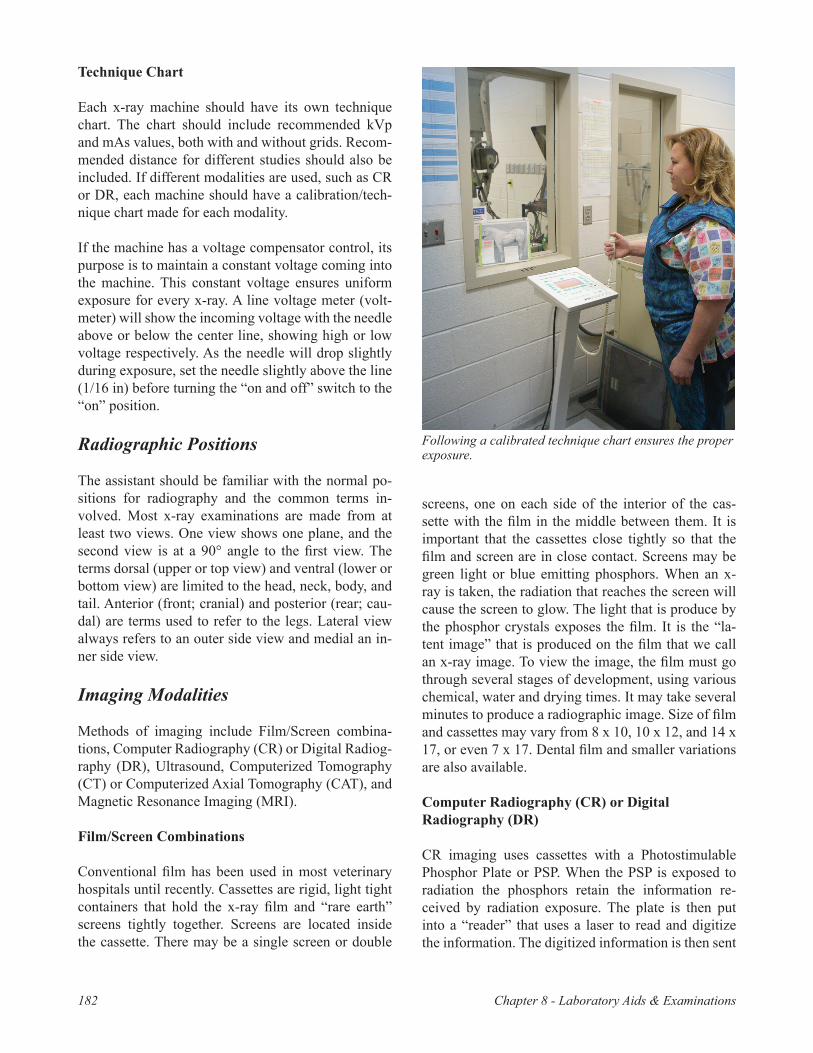
Technique Chart
Each x-ray machine should have its own technique chart. The chart should include recommended kVp and mAs values, both with and without grids. Recom-mended distance for different studies should also be included. If different modalities are used, such as CR or DR, each machine should have a calibration/tech-nique chart made for each modality.
If the machine has a voltage compensator control, its purpose is to maintain a constant voltage coming into the machine. This constant voltage ensures uniform exposure for every x-ray. A line voltage meter (volt-meter) will show the incoming voltage with the needle above or below the center line, showing high or low voltage respectively. As the needle will drop slightly during exposure, set the needle slightly above the line (1/16 in) before turning the “on and off” switch to the “on” position.
Radiographic Positions
The assistant should be familiar with the normal po-sitions for radiography and the common terms in-volved. Most x-ray examinations are made from at least two views. One view shows one plane, and the second view is at a 90° angle to the first view. The terms dorsal (upper or top view) and ventral (lower or bottom view) are limited to the head, neck, body, and tail. Anterior (front; cranial) and posterior (rear; cau-dal) are terms used to refer to the legs. Lateral view always refers to an outer side view and medial an in-ner side view.
Imaging Modalities
Methods of imaging include Film/Screen combina-tions, Computer Radiography (CR) or Digital Radiog-raphy (DR), Ultrasound, Computerized Tomography (CT) or Computerized Axial Tomography (CAT), and Magnetic Resonance Imaging (MRI).
Film/Screen Combinations
Conventional film has been used in most veterinary hospitals until recently. Cassettes are rigid, light tight containers that hold the x-ray film and “rare earth” screens tightly together. Screens are located inside the cassette. There may be a single screen or double
screens, one on each side of the interior of the cas-sette with the film in the middle between them. It is important that the cassettes close tightly so that the film and screen are in close contact. Screens may be green light or blue emitting phosphors. When an x-ray is taken, the radiation that reaches the screen will cause the screen to glow. The light that is produce by the phosphor crystals exposes the film. It is the “la-tent image” that is produced on the film that we call an x-ray image. To view the image, the film must go through several stages of development, using various chemical, water and drying times. It may take several minutes to produce a radiographic image. Size of film and cassettes may vary from 8 x 10, 10 x 12, and 14 x 17, or even 7 x 17. Dental film and smaller variations are also available.
Computer Radiography (CR) or Digital Radiography (DR)
CR imaging uses cassettes with a Photostimulable Phosphor Plate or PSP. When the PSP is exposed to radiation the phosphors retain the information re-ceived by radiation exposure. The plate is then put into a “reader” that uses a laser to read and digitize the information. The digitized information is then sent
Following a calibrated technique chart ensures the proper exposure.
Chapter 8 - Laboratory Aids & Examinations 183
to a computer where the image may be viewed. The digitized image looks like a conventional x-ray im-age. With the use of the computers and programming, the image maybe adjusted to enhance the image and change contrast.
After the plate is read, light is then used to erase the image and to refresh the PSP, making it ready for the next time it is needed. Photostimulable phosphor plates may be used and refreshed over 50,000 times before they need to be replaced. There are no chemi-cals used and the images may be stored on comput-ers, eliminating the storage space needed for filing and storing film or “hard’ copies of radiographic images.
Tissue Density
A radiographic image is composed of black, white, and many shades of gray. The black areas usually rep-resent air. Air outside the body, and in air-filled struc-tures such as the trachea, the stomach and intestines, may also appear dark grey to black. Gray represents soft tissue structures like body fat or fluid densities. White may represent bone or mineral densities, milk, whey, calcium, or sand. Dental enamel and metallic densities will also appear white.
Patient Motion
There are two types of motion voluntary and invol-untary. Voluntary motion is controlled motion. The animal might be looking around, moving away from noises and unfamiliar objects. It may also be mov-ing its extremities, paddling, or pushing away from any kind of restraint. Involuntary motion includes the heart beating and breathing. When imaging an animal that is panting or in discomfort reduce the exposure time and increase the mA station. If an animal is mov-ing, restraint may be necessary. When imaging the thorax, lungs, and heart, watch closely for inspiration and expiration. As the animal inhales, make the ex-posure. When imaging the abdomen, pelvis, or spine, make the exposure as the animal exhales.
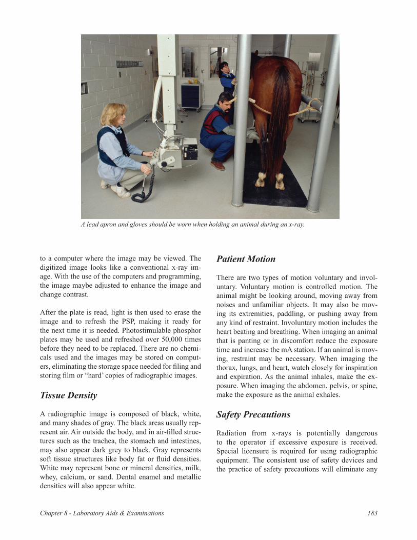
Safety Precautions
Radiation from x-rays is potentially dangerous to the operator if excessive exposure is received. Special licensure is required for using radiographic equipment. The consistent use of safety devices and the practice of safety precautions will eliminate any
A lead apron and gloves should be worn when holding an animal during an x-ray.

Chapter 8 - Laboratory Aids & Examinations184
hazard from excessive radiation. Safety devices and precautions include the following:
• Remove anyone from the x-ray room that is not needed.
• Every person should wear a lead apron and lead gloves when holding the x-rayed animal.
• Check the condition of gloves and aprons periodi-cally by using radiography to determine if they al-low x-rays to pass through.
• Limit the beam to the size of the film with a cone or lead diaphragm.
• Do not direct the x-ray beam into another room or work area.
• Install an aluminum filter (1 to 2 mm thick) at the tube housing opening to eliminate radiation from useless wave lengths.
• Cover the bottom side of the x-ray table with lead to protect the feet.
• The hands should not be placed in the path of the direct beam.
• Do not use fluoroscopy when radiography will do the job. Fluoroscopy is more hazardous and re-quires additional safety precautions.
To help prevent deterioration of lead gloves and lead aprons:• Roll or drape apron over curved surface rather
than folding it.• Store gloves by hanging or by placing cans with
both ends open inside gloves to keep the gloves open and to allow moisture to evaporate.
Reference
Bassert, J. M., & McCurnin, D. M. (2010). McCurnin’s clinical textbook for veterinary technicians (7th ed.). St. Louis, MO: Saunders Elsevier.
Questions
1. Describe nine safety precautions that should be observed when performing an x-ray.
2. How should lead aprons and gloves be stored to prevent deterioration?
3. Describe the steps for determining the machine settings for a radiograph.
4. What is a grid? What is its purpose?
Fill-in-the-Blank
5. A _____ is an instrument used to measure the thickness (in centimeters) of the part of the animal to be x-rayed.
6. A _____ will show the incoming voltage of an x-ray machine.
7. _____ is a term that refers to the front, or cranial, part of an animal.
8. Lateral always refers to the _____ view.9. For safety purposes, every person in the x-ray
room should wear _____ _____ during the x-ray.10. A cone or _____ _____ should be used to limit the
size of the x-ray beam.
True/False
11. T F Radiography is more hazardous than fluoroscopy.
12. T F Use the slowest exposure time possible when performing an x-ray.
13. T F Use the highest kV setting possible (up to 90 kV) when performing an x-ray.
14. T F The purpose of a voltage compensator control is to maintain a constant voltage coming into the radiograph machine.
15. T F It is recommended that people who are not needed to perform the radiograph remain in the x-ray room to view the procedure.
16. T F Covering the bottom side of the x-ray table with lead will help protect the feet.
Activities
1. Measure the anterior-posterior thickness in cen-timeters of a dog’ s foot. Determine the proper machine settings (kV, mA, time, and distance) by referring to the technique chart to make an anteri-or-posterior radiograph of the dog’s foot.
2. Study the proper use of the dial settings of a radio-graph machine and set the dials on the machine to radiograph the dog’s foot in Activity 1.
3. Observe a veterinarian or veterinary assistant us-ing a radiograph machine and taking radiographs of several animals. Observe the veterinarian’s safety precautions and practices. List your obser-vations.