radiographs in endodontic diagnosis
TRANSCRIPT

RADIOGRAPHIC INTERPRETATIONS IN
ENDODONTIC DIAGNOSIS
Liya Alice Thomas
CONTENTSIntroduction
History
Terminology
Radiographic techniques
Interpretation of dental caries
Interpretation of trauma, pulpal & periapical lesions
Interpretation of restorations & dental materials
Interpretation of root canal anatomy
Conclusion
References
INTRODUCTION

HISTORY
•Feb 1895 – discovery of cathode rays by Prof. Wilhelm Roentgen
•14 days later – Dr.Otto Walkoff took the first dental X-ray in his own mouth
•3 months later – Dr.C. Edmund Kells installed the first X-ray machine in his clinic
•1899 – Dr. C.Edmund Kells used X-rays for working length determination (FATHER
OF DENTAL RADIOLOGY)
•1900 – Dr. Weston Price used radiographs to detect inadequately filled root canals.
developed bisecting angle technique.

TERMINOLOGY
•IMAGE INTERPRETATION – An explanation of what is viewed on a dental image <or> the ability to read what is revealed by a dental image
•DIAGNOSIS – The identification of a disease by examination or analysis
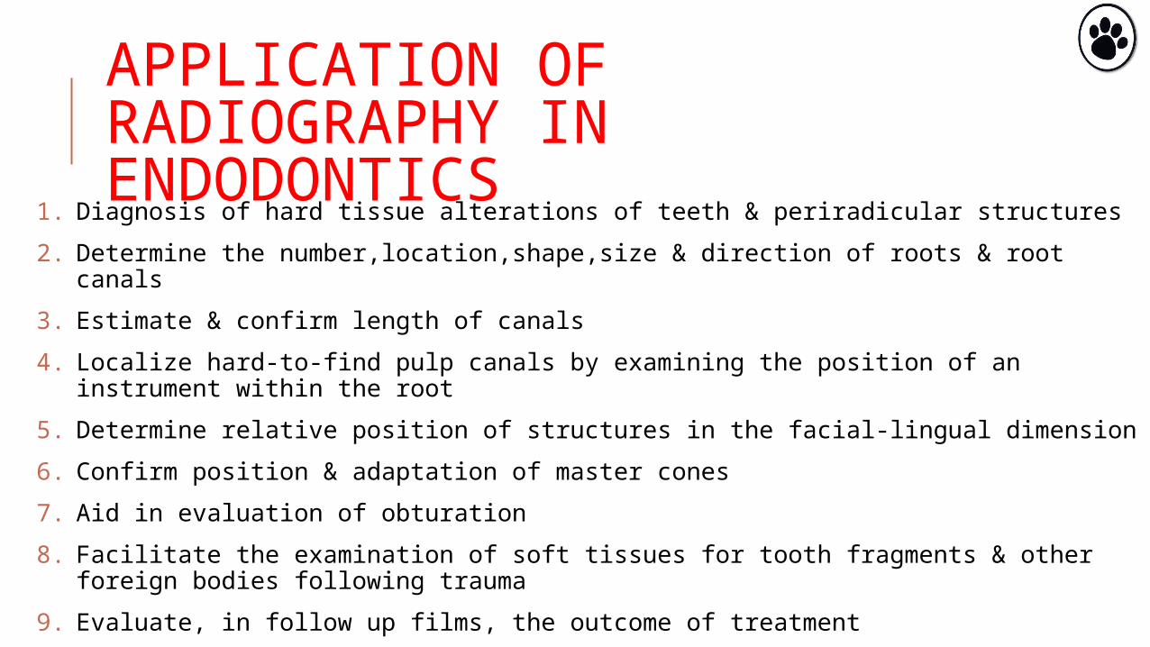
APPLICATION OF RADIOGRAPHY IN ENDODONTICS
1. Diagnosis of hard tissue alterations of teeth & periradicular structures
2. Determine the number,location,shape,size & direction of roots & root canals
3. Estimate & confirm length of canals
4. Localize hard-to-find pulp canals by examining the position of an instrument within the root
5. Determine relative position of structures in the facial-lingual dimension
6. Confirm position & adaptation of master cones
7. Aid in evaluation of obturation
8. Facilitate the examination of soft tissues for tooth fragments & other foreign bodies following trauma
9. Evaluate, in follow up films, the outcome of treatment

LIMITATIONS OF RADIOGRAPHS
1. Can be easily distorted through improper technique, anatomic limitations or processing errors
2. Buccal-lingual dimension is absent on a single film
3. Various states of pulpal pathosis are indistingushable.Neither healthy nor necrotic pulps cast an unusual image
4. The bacterial status of hard or soft tissue is not detectable-microbiological inference
5. Periradicular soft tissue lesions cannot be diagnosed accurately-histological inference
6. C/c inflammatory tissue cannot be distinguished from healed, fibrous scar tissue
Goldman M,Pearson A,Darzenta N.Endodontic success-who’s reading the radiograph? Oral Surg Oral Med Oral Pathol Oral Radiol Endod 1972;23:432
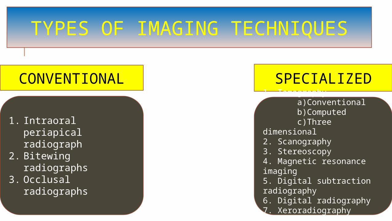
TYPES OF IMAGING TECHNIQUES
CONVENTIONAL SPECIALIZED
1. Intraoral periapical radiograph
2. Bitewing radiographs3. Occlusal radiographs
1. Tomography a)Conventional b)Computed c)Three dimensional2. Scanography3. Stereoscopy4. Magnetic resonance imaging5. Digital subtraction radiography6. Digital radiography7. Xeroradiography8. CBCT
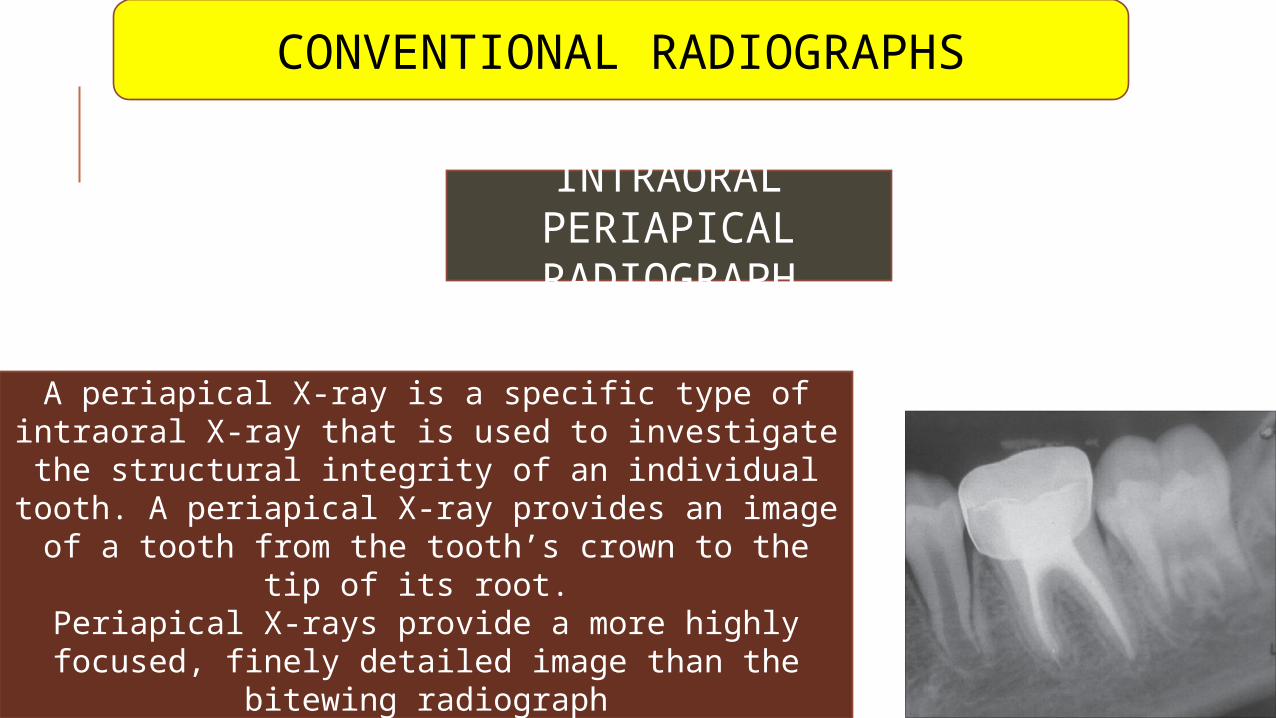
INTRAORAL PERIAPICAL
RADIOGRAPH
A periapical X-ray is a specific type of intraoral X-ray that is used to investigate the structural
integrity of an individual tooth. A periapical X-ray provides an image of a tooth from the tooth’s
crown to the tip of its root. Periapical X-rays provide a more highly focused,
finely detailed image than the bitewing radiograph
CONVENTIONAL RADIOGRAPHS
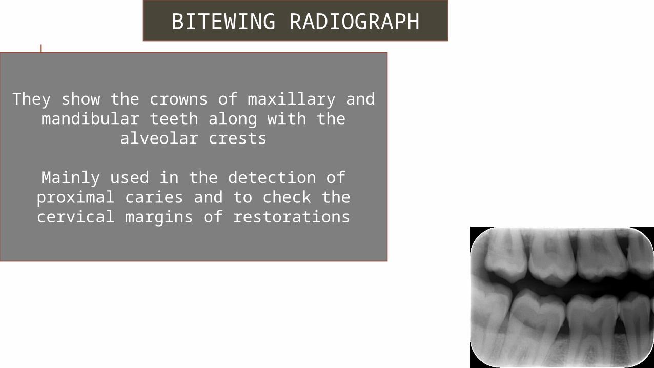
BITEWING RADIOGRAPH
They show the crowns of maxillary and mandibular teeth along with the alveolar
crests
Mainly used in the detection of proximal caries and to check the cervical margins of
restorations
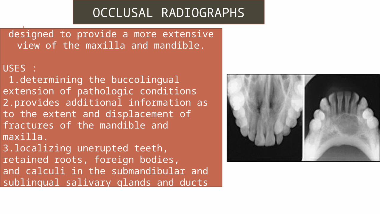
OCCLUSAL RADIOGRAPHS
designed to provide a more extensive view of the maxilla and mandible.
USES : 1.determining the buccolingual extension of pathologic conditions2.provides additional information as to the extent and displacement of fractures of the mandible and maxilla. 3.localizing unerupted teeth, retained roots, foreign bodies, and calculi in the submandibular and sublingual salivary glands and ducts
SPECIALIZED RADIOGRAPHS
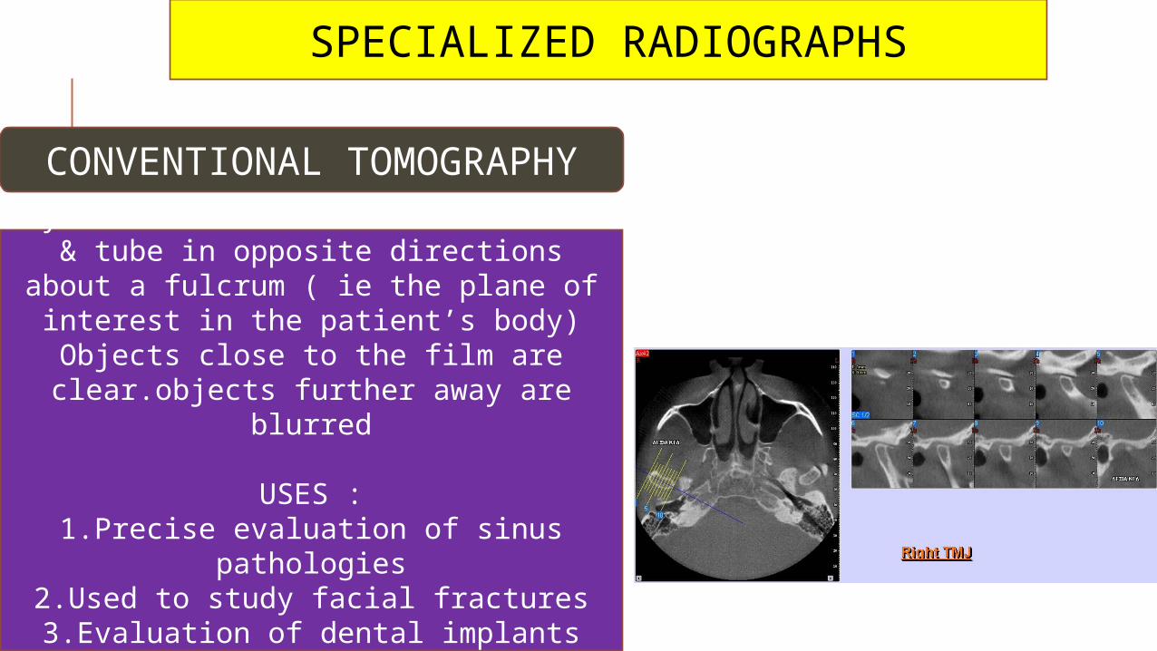
CONVENTIONAL TOMOGRAPHY
Synchronized movement of the film & tube in opposite directions about a
fulcrum ( ie the plane of interest in the patient’s body)
Objects close to the film are clear.objects further away are blurred
USES :1.Precise evaluation of sinus pathologies
2.Used to study facial fractures3.Evaluation of dental implants
4.In diseases of the TMJ
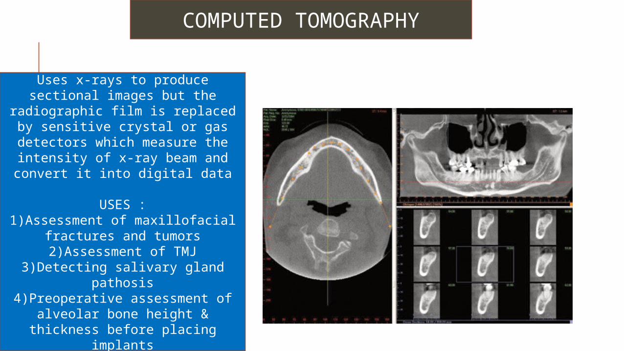
COMPUTED TOMOGRAPHY
Uses x-rays to produce sectional images but the radiographic film is replaced by sensitive crystal or gas
detectors which measure the intensity of x-ray beam and convert
it into digital data
USES :1)Assessment of maxillofacial
fractures and tumors2)Assessment of TMJ
3)Detecting salivary gland pathosis4)Preoperative assessment of
alveolar bone height & thickness before placing implants
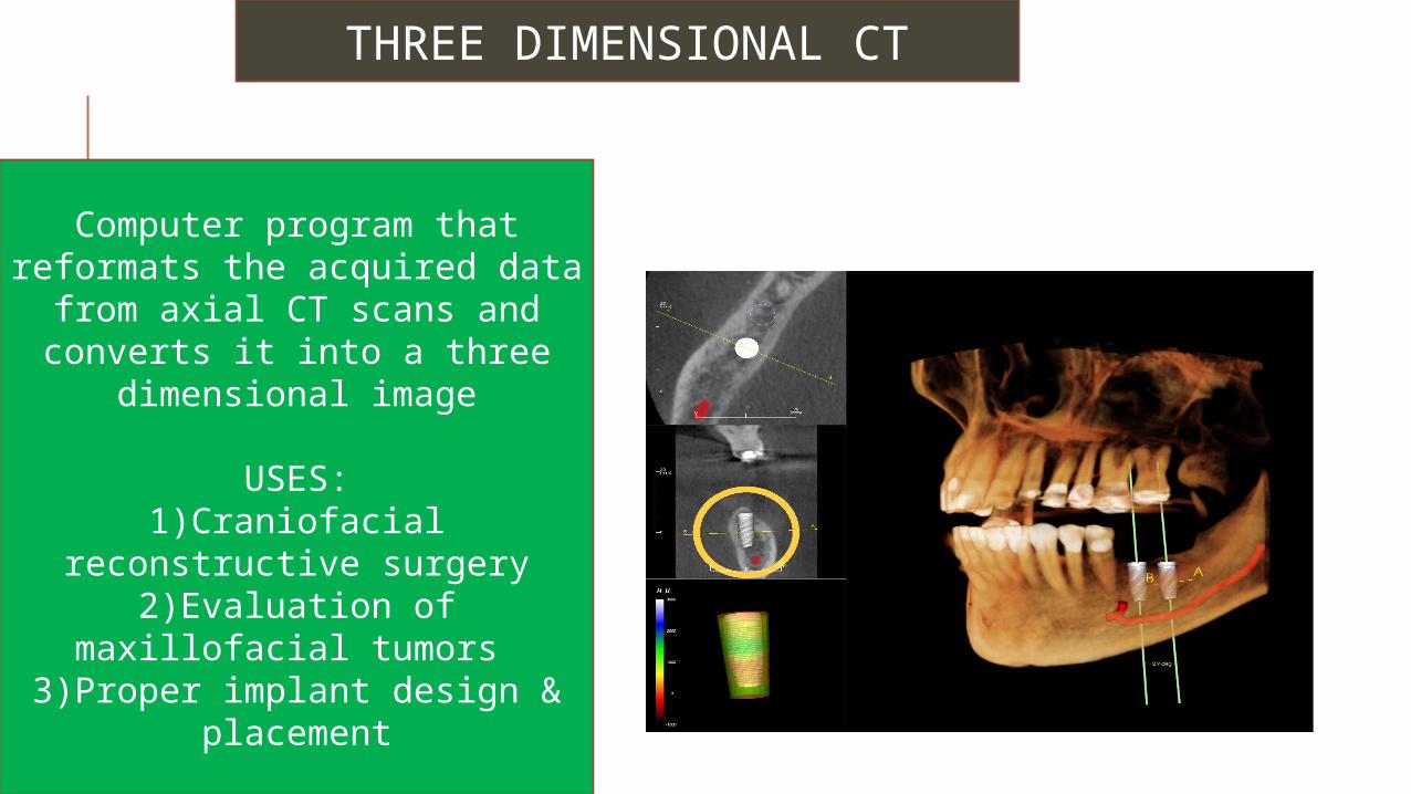
THREE DIMENSIONAL CT
Computer program that reformats the acquired data
from axial CT scans and converts it into a three
dimensional image
USES:1)Craniofacial reconstructive
surgery2)Evaluation of maxillofacial
tumors 3)Proper implant design &
placement
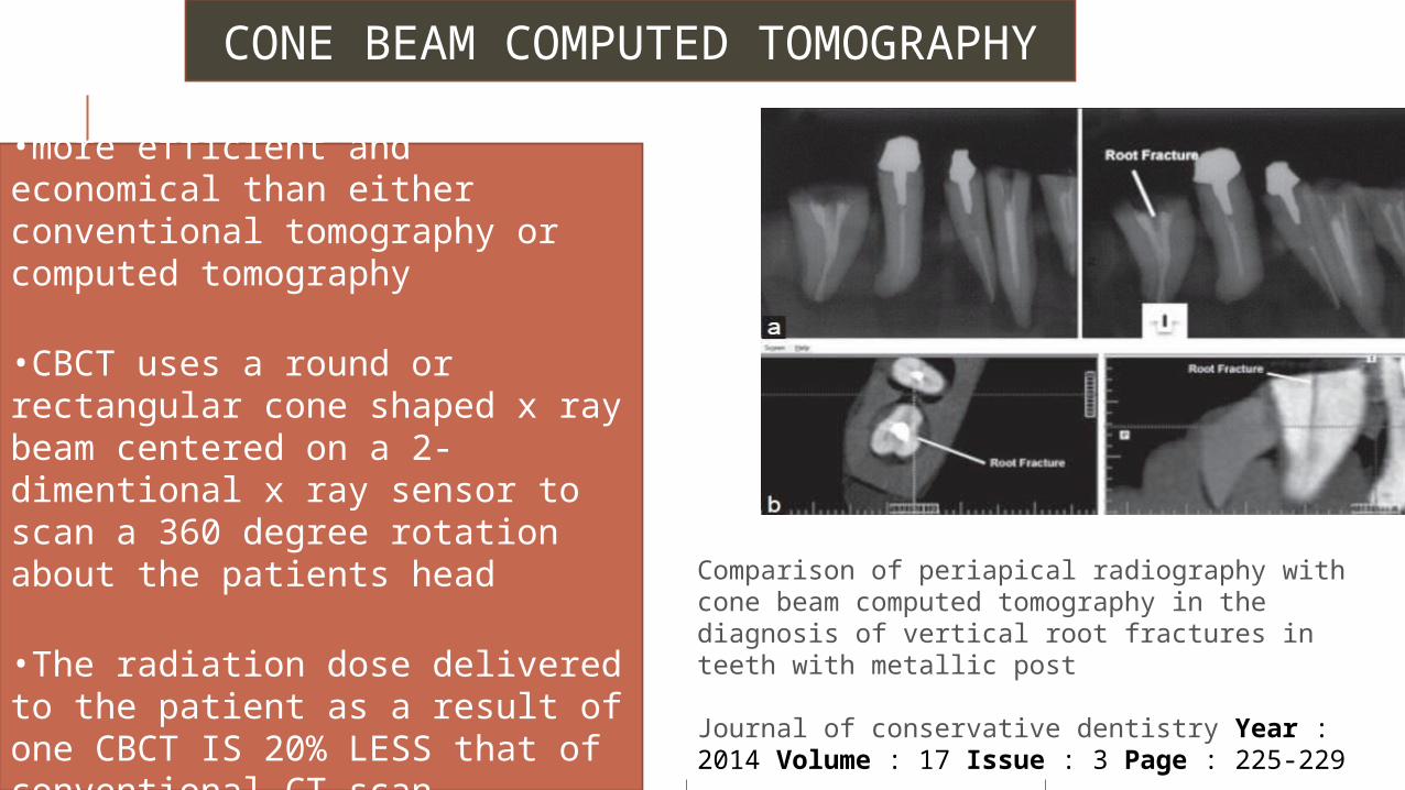
CONE BEAM COMPUTED TOMOGRAPHY
•more efficient and economical than either conventional tomography or computed tomography
•CBCT uses a round or rectangular cone shaped x ray beam centered on a 2-dimentional x ray sensor to scan a 360 degree rotation about the patients head
•The radiation dose delivered to the patient as a result of one CBCT IS 20% LESS that of conventional CT scan
Comparison of periapical radiography with cone beam computed tomography in the diagnosis of vertical root fractures in teeth with metallic post
Journal of conservative dentistry Year : 2014 Volume : 17 Issue : 3 Page : 225-229
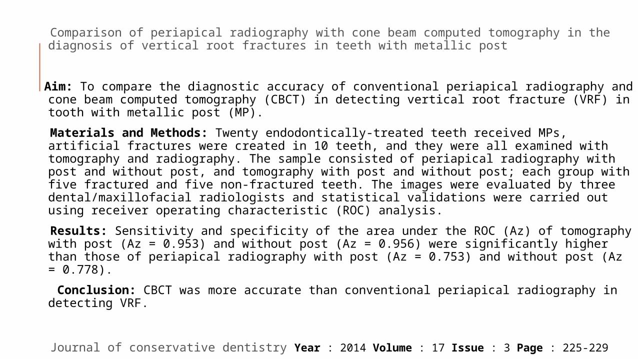
Comparison of periapical radiography with cone beam computed tomography in the diagnosis of vertical root fractures in teeth with metallic post
Aim: To compare the diagnostic accuracy of conventional periapical radiography and cone beam computed tomography (CBCT) in detecting vertical root fracture (VRF) in tooth with metallic post (MP).
Materials and Methods: Twenty endodontically-treated teeth received MPs, artificial fractures were created in 10 teeth, and they were all examined with tomography and radiography. The sample consisted of periapical radiography with post and without post, and tomography with post and without post; each group with five fractured and five non-fractured teeth. The images were evaluated by three dental/maxillofacial radiologists and statistical validations were carried out using receiver operating characteristic (ROC) analysis.
Results: Sensitivity and specificity of the area under the ROC (Az) of tomography with post (Az = 0.953) and without post (Az = 0.956) were significantly higher than those of periapical radiography with post (Az = 0.753) and without post (Az = 0.778).
Conclusion: CBCT was more accurate than conventional periapical radiography in detecting VRF.
Journal of conservative dentistry Year : 2014 Volume : 17 Issue : 3 Page : 225-229

SCANOGRAPHY
Uses a narrowly collimated fan shaped beam of radiation to scan an area of interest sequentially projecting image data relative to this area onto a moving film
Higher contrast & better details
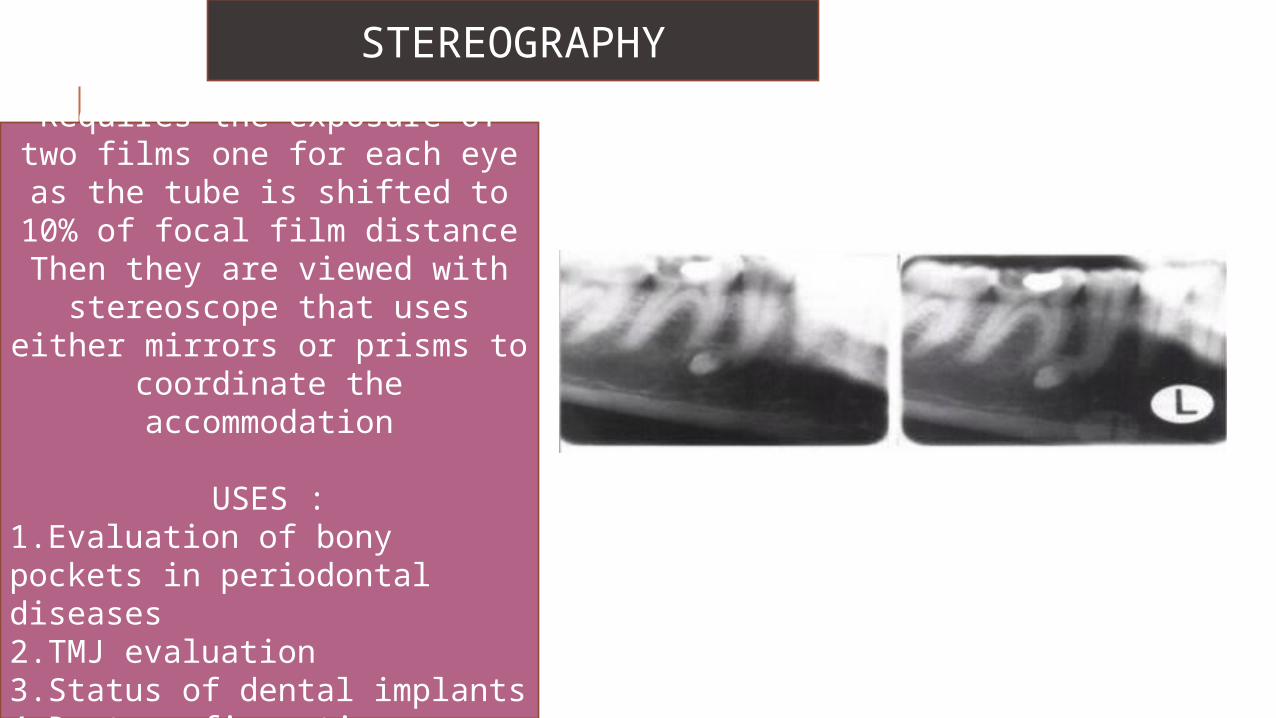
STEREOGRAPHY
Requires the exposure of two films one for each eye as the tube is shifted to 10% of focal
film distanceThen they are viewed with
stereoscope that uses either mirrors or prisms to coordinate
the accommodation
USES :1.Evaluation of bony pockets in periodontal diseases2.TMJ evaluation3.Status of dental implants4.Root configurations
Stereographic assessment vs.clinical assessment of mandibular canal in relation to the roots of impacted lower third molar
The position of the mandibular canal in relation to the superimposed roots of 173 impacted lower 3rd molars was evaluated radiologically. Stereography technique recently developed for oral radiography was applied in this study. The mandibular canal was located buccally to the roots of 105 (61%) teeth, lingually to the roots of 57 (33%) teeth, and between the roots of 6 (3%) teeth. The relationship of canal to roots of 5 (3%) teeth was not possible to determine.
Disagreement between radiological assessment and clinical observation was found in 4 (5%) of 80 operated teeth. The canal was visible at operation in 23 (29%) cases, which was predicted at stereographic examination in 21(91%) cases.
The stereographic technique is a useful method with high sensitivity (0.83) for evaluating the bucco-lingual relationship of the mandibular canal to the roots of a 3rd molar.
International Journal of Oral and Maxillofacial Surgery Volume 21, Issue 2, April 1992, Pages 85–89
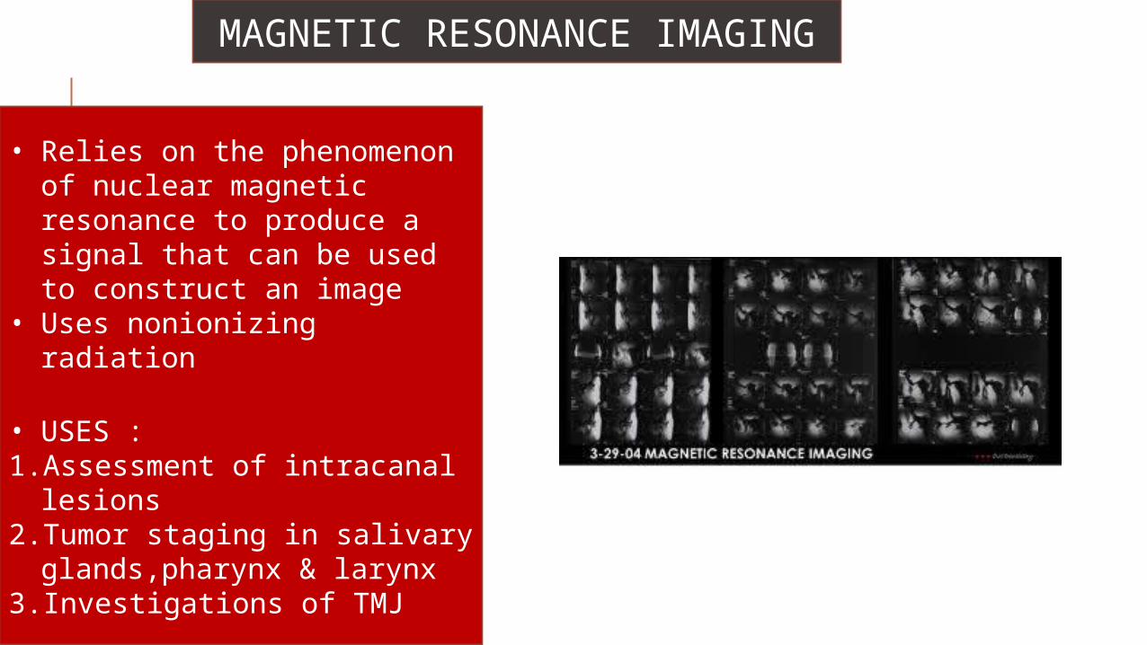
MAGNETIC RESONANCE IMAGING
• Relies on the phenomenon of nuclear magnetic resonance to produce a signal that can be used to construct an image
• Uses nonionizing radiation
• USES :1. Assessment of intracanal
lesions2. Tumor staging in salivary
glands,pharynx & larynx3. Investigations of TMJ
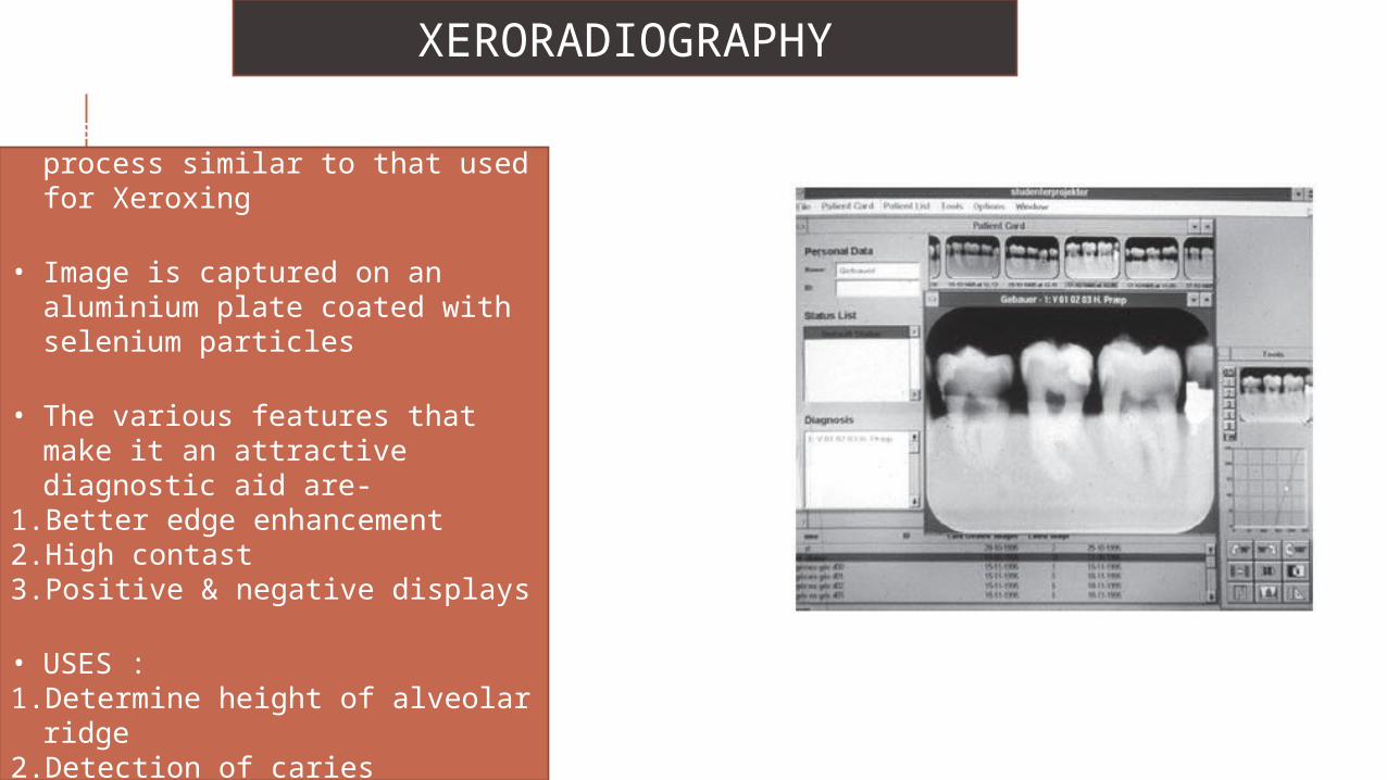
XERORADIOGRAPHY
• Based on an electrostatic process similar to that used for Xeroxing
• Image is captured on an aluminium plate coated with selenium particles
• The various features that make it an attractive diagnostic aid are-
1.Better edge enhancement2.High contast3.Positive & negative displays
• USES :1. Determine height of alveolar
ridge2. Detection of caries3. endodontics
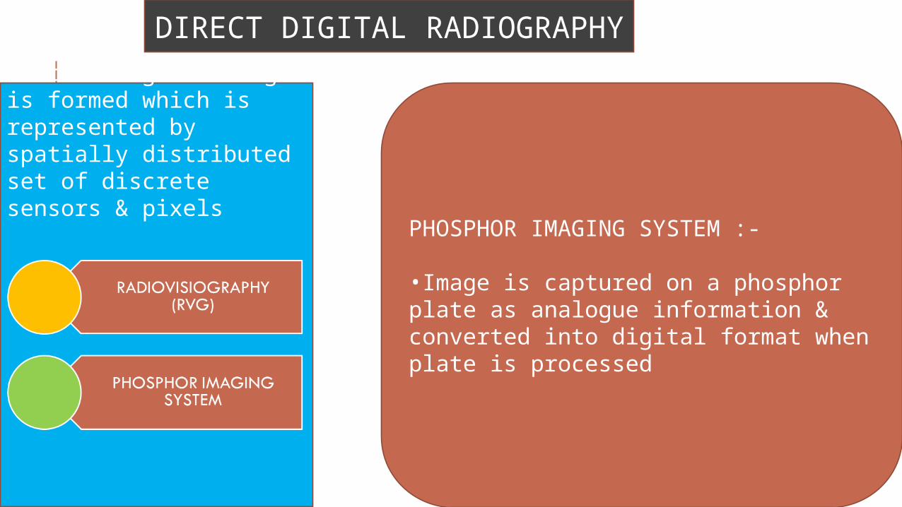
DIRECT DIGITAL RADIOGRAPHY
In this digital image is formed which is represented by spatially distributed set of discrete sensors & pixels
PHOSPHOR IMAGING SYSTEM :-
•Image is captured on a phosphor plate as analogue information & converted into digital format when plate is processed
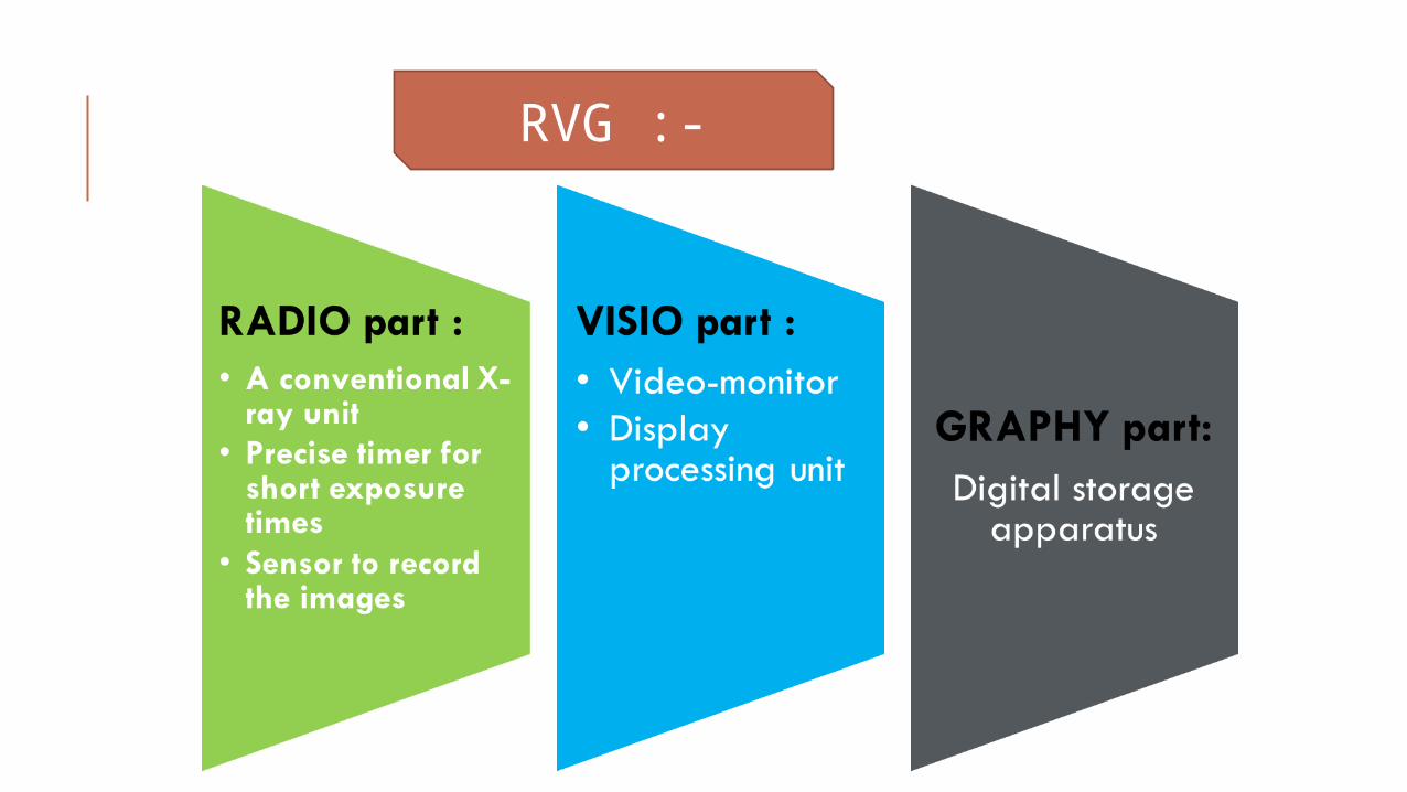
RVG :-
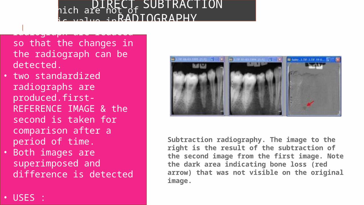
DIRECT SUBTRACTION RADIOGRAPHY• Images which are not of
diagnostic value in a radiograph are reduced so that the changes in the radiograph can be detected.
• two standardized radiographs are produced.first-REFERENCE IMAGE & the second is taken for comparison after a period of time.
• Both images are superimposed and difference is detected
• USES :1.Assess
progression/regression of carious lesions
Subtraction radiography. The image to the right is the result of the subtraction of the second image from the first image. Note the dark area indicating bone loss (red arrow) that was not visible on the original image.
INTERPRETATION OF DENTAL CARIESCariosus (LATIN) - rottenness
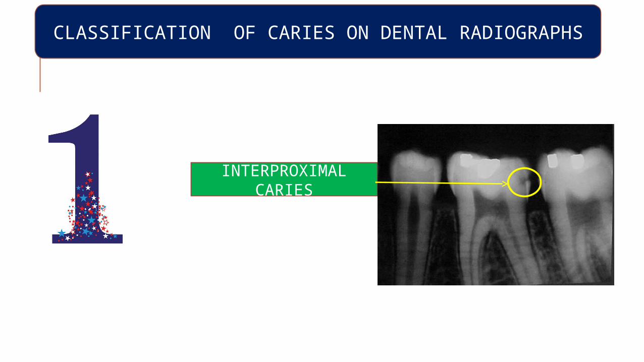
CLASSIFICATION OF CARIES ON DENTAL RADIOGRAPHS
INTERPROXIMAL CARIES
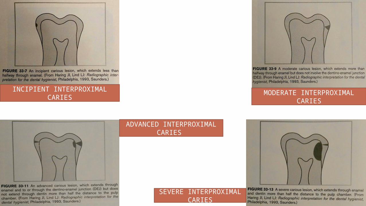
INCIPIENT INTERPROXIMAL CARIES
MODERATE INTERPROXIMAL CARIES
ADVANCED INTERPROXIMAL CARIES
SEVERE INTERPROXIMAL CARIES
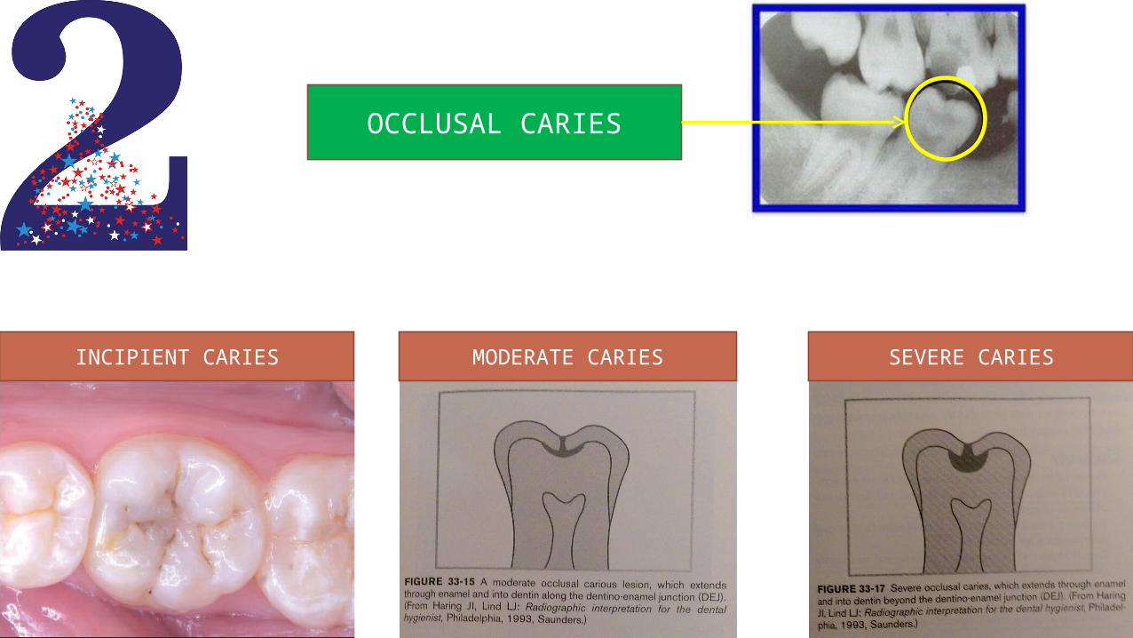
OCCLUSAL CARIES
INCIPIENT CARIES MODERATE CARIES SEVERE CARIES
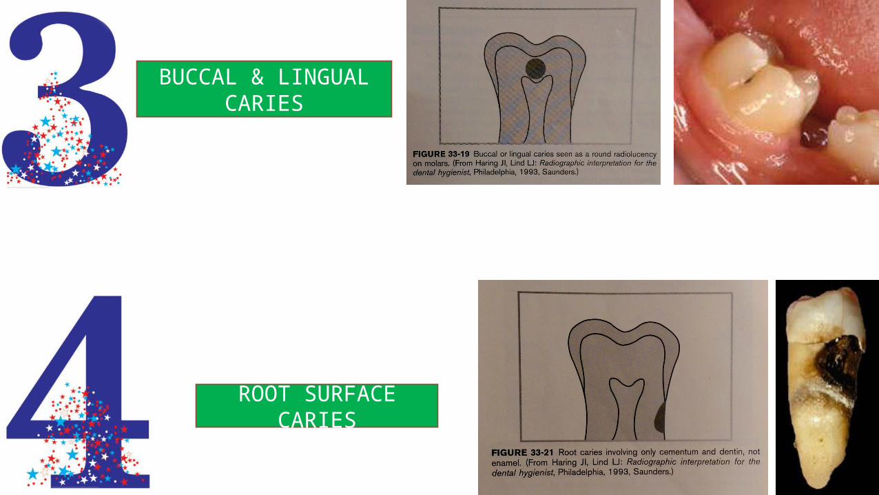
BUCCAL & LINGUAL CARIES
ROOT SURFACE CARIES
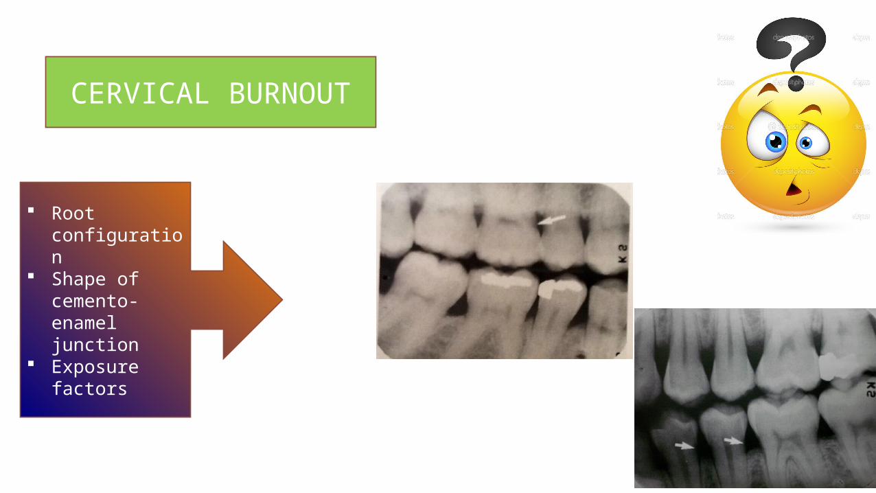
CERVICAL BURNOUT
Root configuration
Shape of cemento-enamel junction
Exposure factors
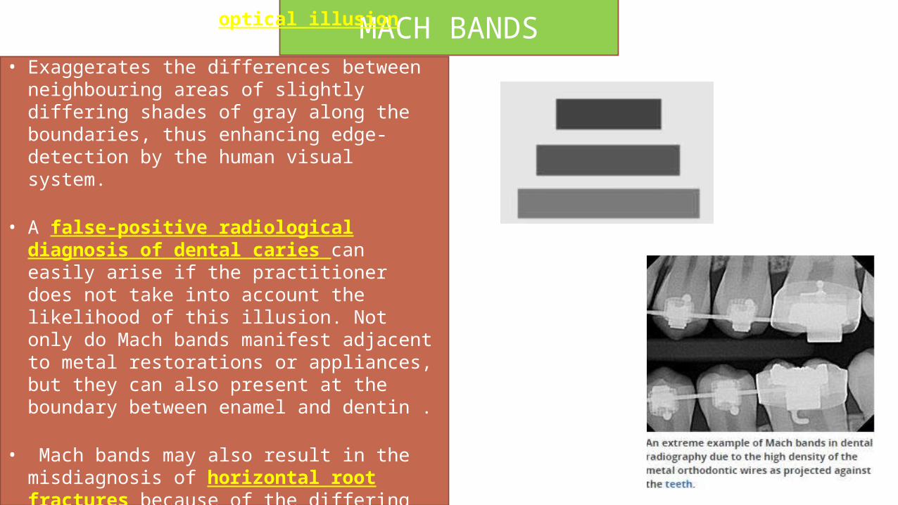
MACH BANDS• Mach bands is an optical illusion
• Exaggerates the differences between neighbouring areas of slightly differing shades of gray along the boundaries, thus enhancing edge-detection by the human visual system.
• A false-positive radiological diagnosis of dental caries can easily arise if the practitioner does not take into account the likelihood of this illusion. Not only do Mach bands manifest adjacent to metal restorations or appliances, but they can also present at the boundary between enamel and dentin .
• Mach bands may also result in the misdiagnosis of horizontal root fractures because of the differing radiographic intensities of tooth and bone
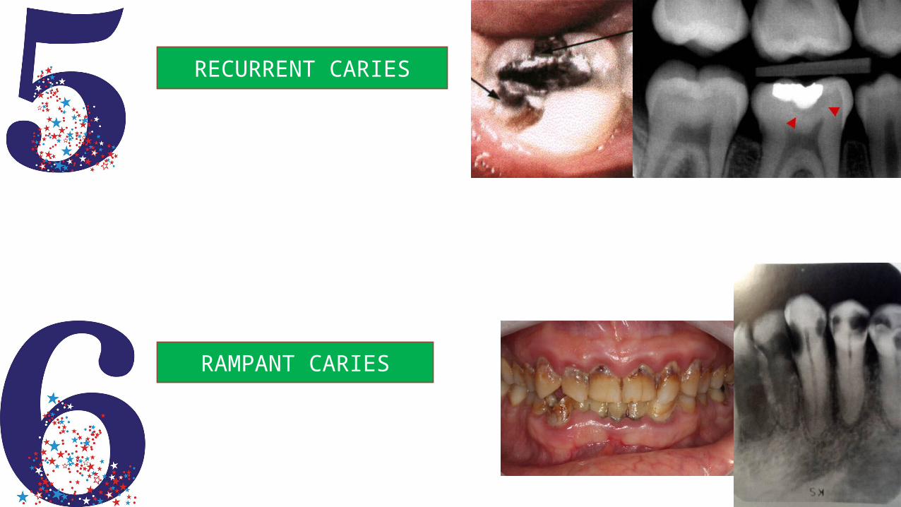
RECURRENT CARIES
RAMPANT CARIES
INTERPRETATION OF TRAUMA, PULPAL AND PERIAPICAL LESIONS
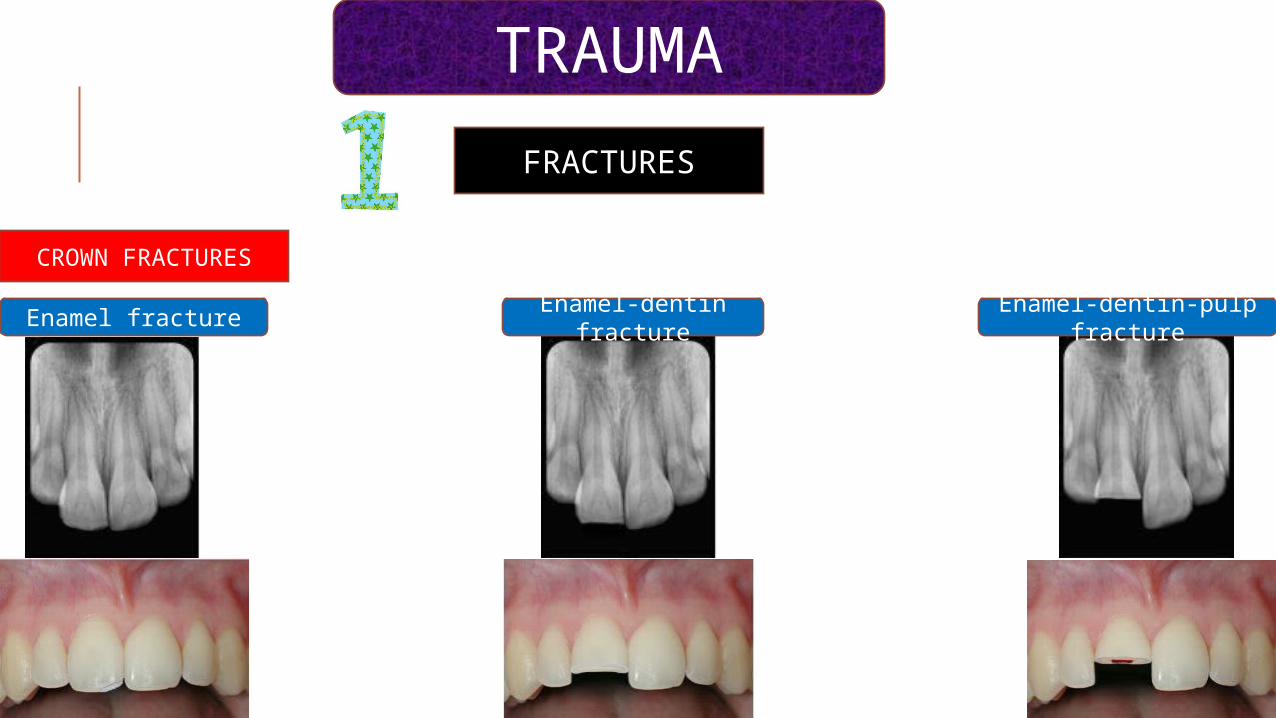
FRACTURES
CROWN FRACTURES
TRAUMA
Enamel fractureEnamel-dentin
fractureEnamel-dentin-pulp
fracture
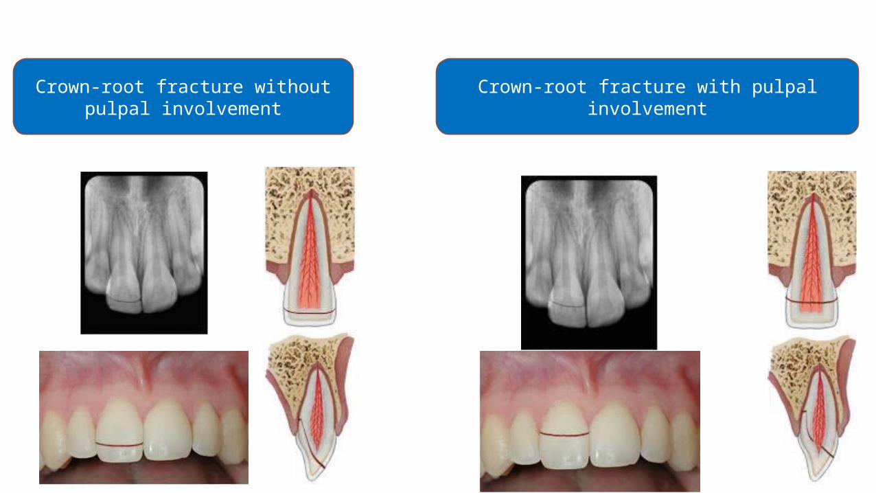
Crown-root fracture without pulpal involvement
Crown-root fracture with pulpal involvement

ROOT FRACTURES
HORIZONTAL ROOT FRACTURE
VERTICAL ROOT FRACTURE
A)At one year recall there is no evidence of any radiographic
changes which are suggestive of a problem
B)Two years later there is widening of the periodontal
ligament space & the appearance of a large periapical lesion.the
fracture is seen as a space which has developed on the distal side
of the filling due to slight separation of the fragments
Moule AJ, Kahler B. Diagnosis and management of teeth with vertical root fractures Australian Dental Journal 1999; 44(2): 75-87
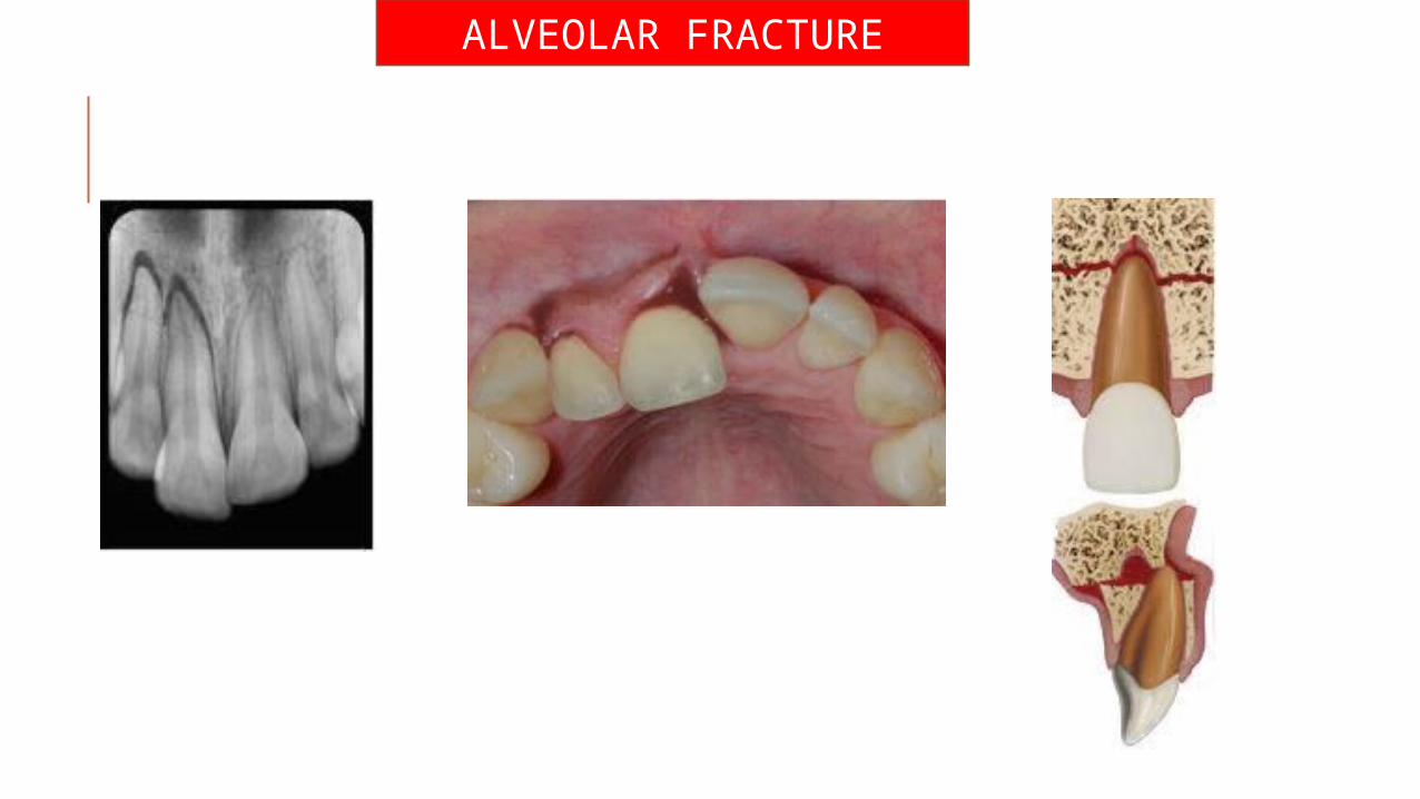
ALVEOLAR FRACTURE
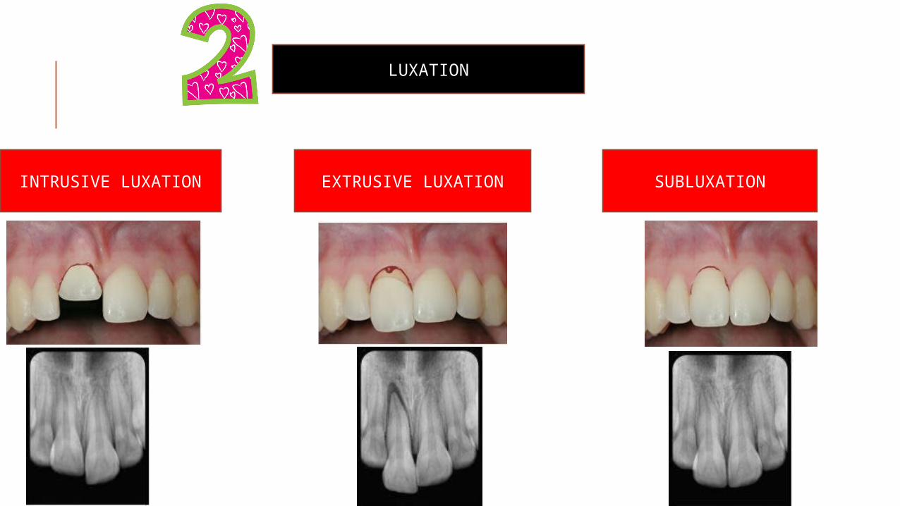
LUXATION
INTRUSIVE LUXATION EXTRUSIVE LUXATION SUBLUXATION
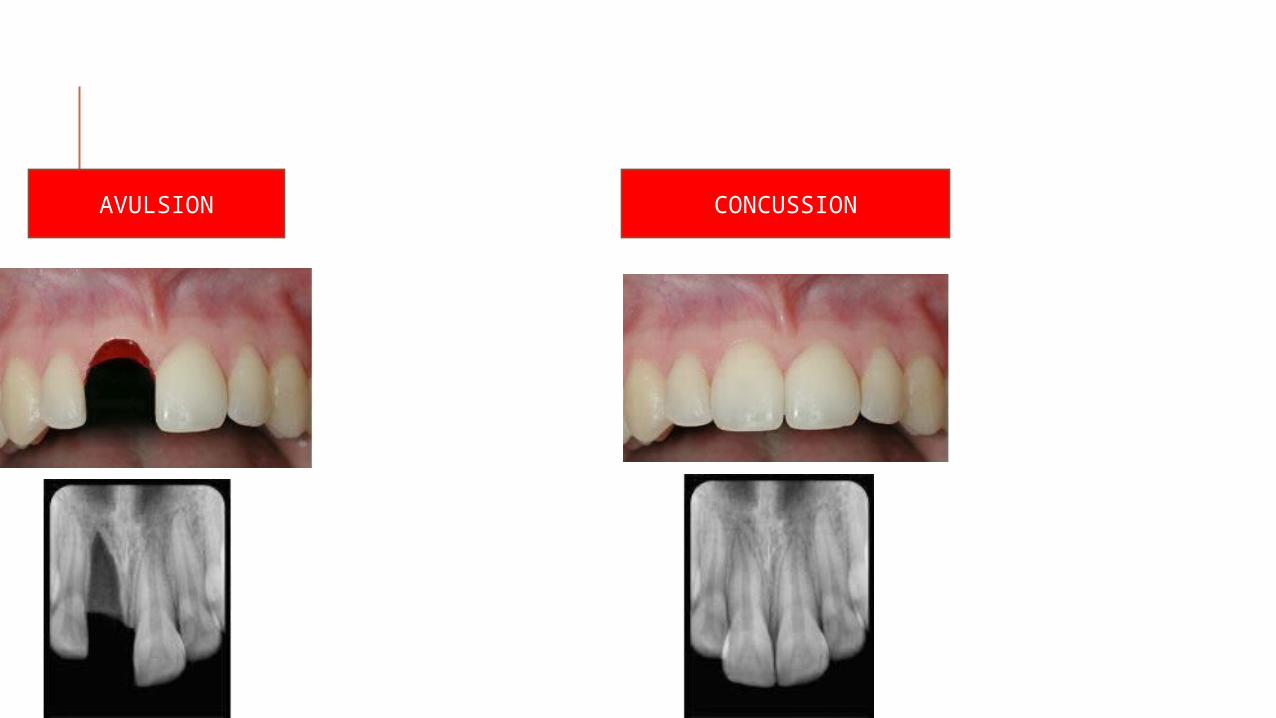
AVULSION CONCUSSION
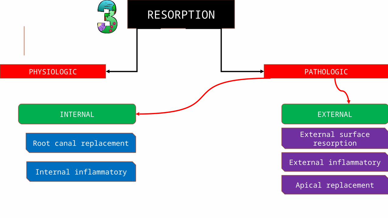
RESORPTION
PHYSIOLOGIC PATHOLOGIC
INTERNAL EXTERNAL
Root canal replacement
Internal inflammatory
External surface resorption
External inflammatory
Apical replacement
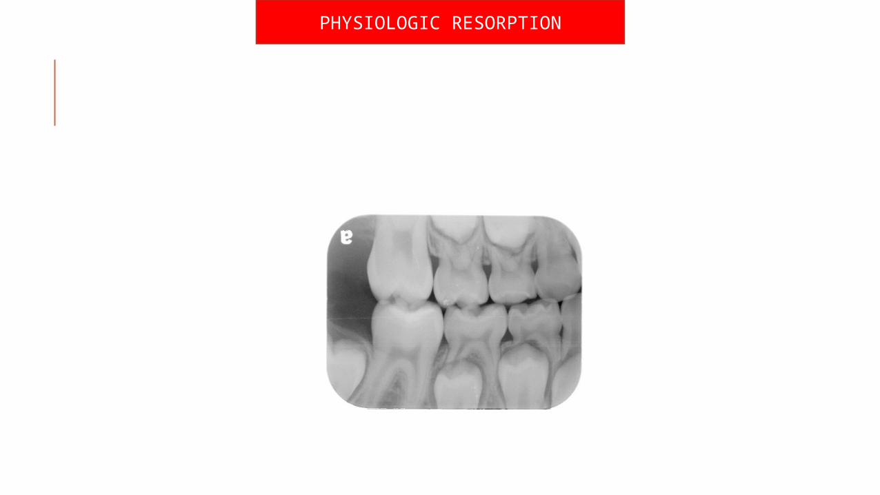
PHYSIOLOGIC RESORPTION
PATHOLOGIC RESORPTION
EXTERNAL RESORPTION
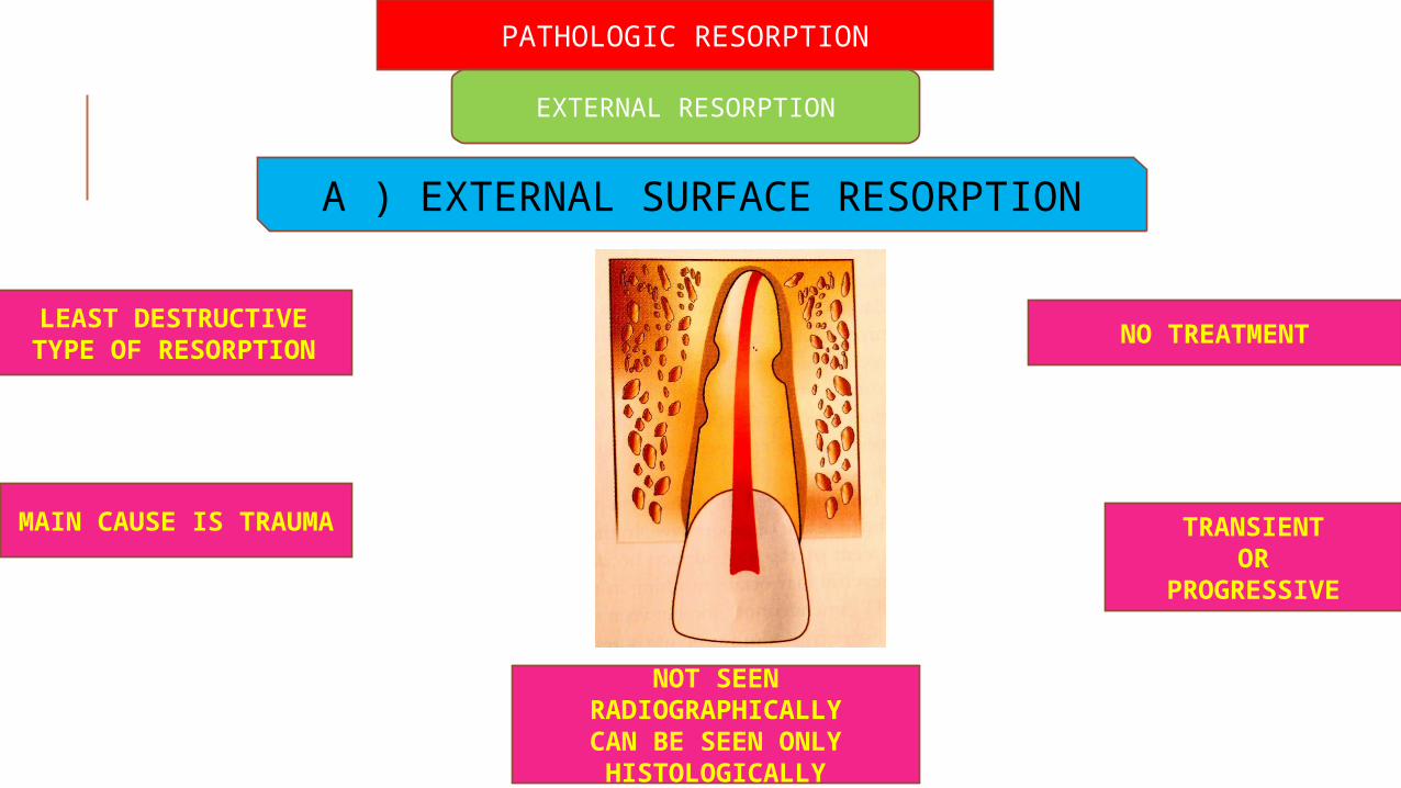
A ) EXTERNAL SURFACE RESORPTION
LEAST DESTRUCTIVE TYPE OF RESORPTION
MAIN CAUSE IS TRAUMA
NOT SEEN RADIOGRAPHICALLYCAN BE SEEN ONLY HISTOLOGICALLY
NO TREATMENT
TRANSIENTOR
PROGRESSIVE
B ) EXTERNAL INFLAMMATORY RESORPTION
MOST COMMON & DESTRUCTIVE
ETIOLOGY :1)Injury or irritation
of periodontal tissues
2)Trauma leading to pulp necrosis
3)Excess orthodontic forces
4)Trauma from occlusion
5)Pressure resorption(cyst,tumo
rs)
RADIOGRAPHIC FEATURES :
Bowl like radiolucency with ragged irregular areas seen along with loss of tooth structure
& bone
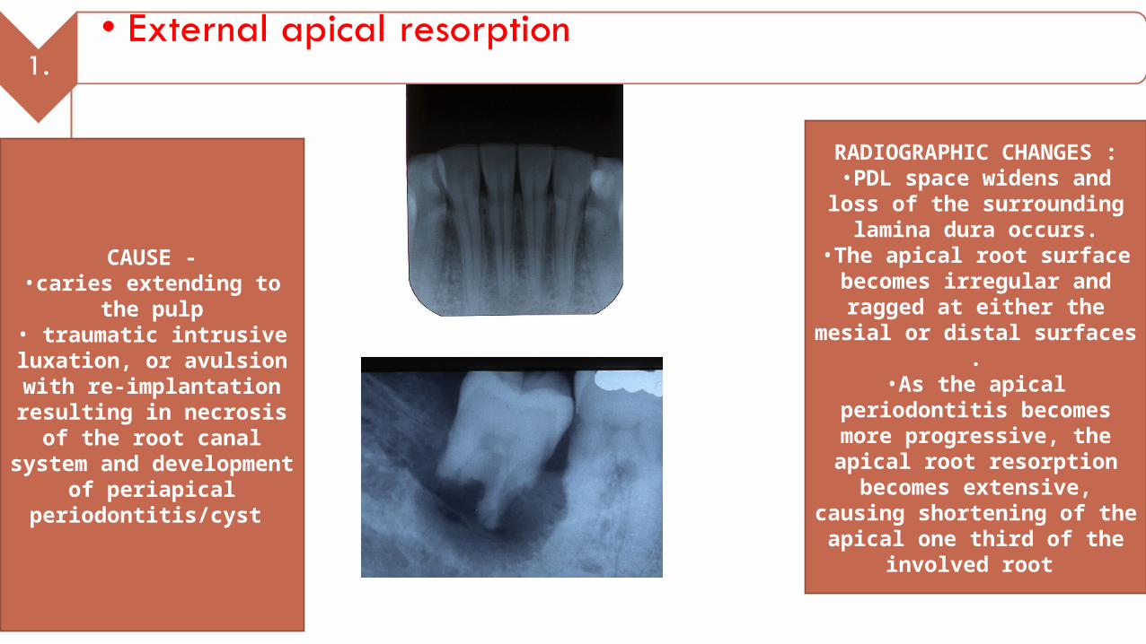
CAUSE -•caries extending to
the pulp• traumatic intrusive luxation, or avulsion with re-implantation
resulting in necrosis of the root canal system and development of
periapical periodontitis/cyst
RADIOGRAPHIC CHANGES :
•PDL space widens and loss of the surrounding
lamina dura occurs.•The apical root surface becomes irregular and ragged at either the
mesial or distal surfaces .•As the apical
periodontitis becomes more progressive, the apical root resorption becomes extensive,
causing shortening of the apical one third of the
involved root
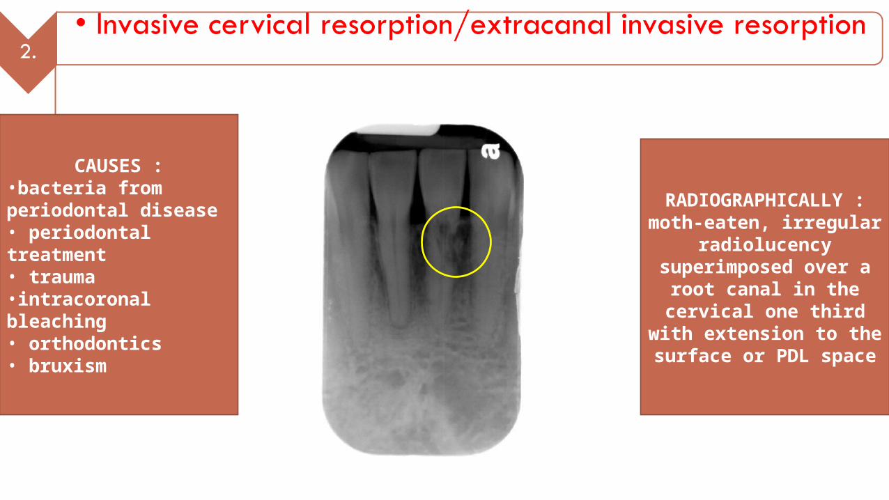
CAUSES :•bacteria from periodontal disease• periodontal treatment• trauma •intracoronal bleaching• orthodontics• bruxism
RADIOGRAPHICALLY :moth-eaten, irregular
radiolucency superimposed over a
root canal in the cervical one third with
extension to the surface or PDL space
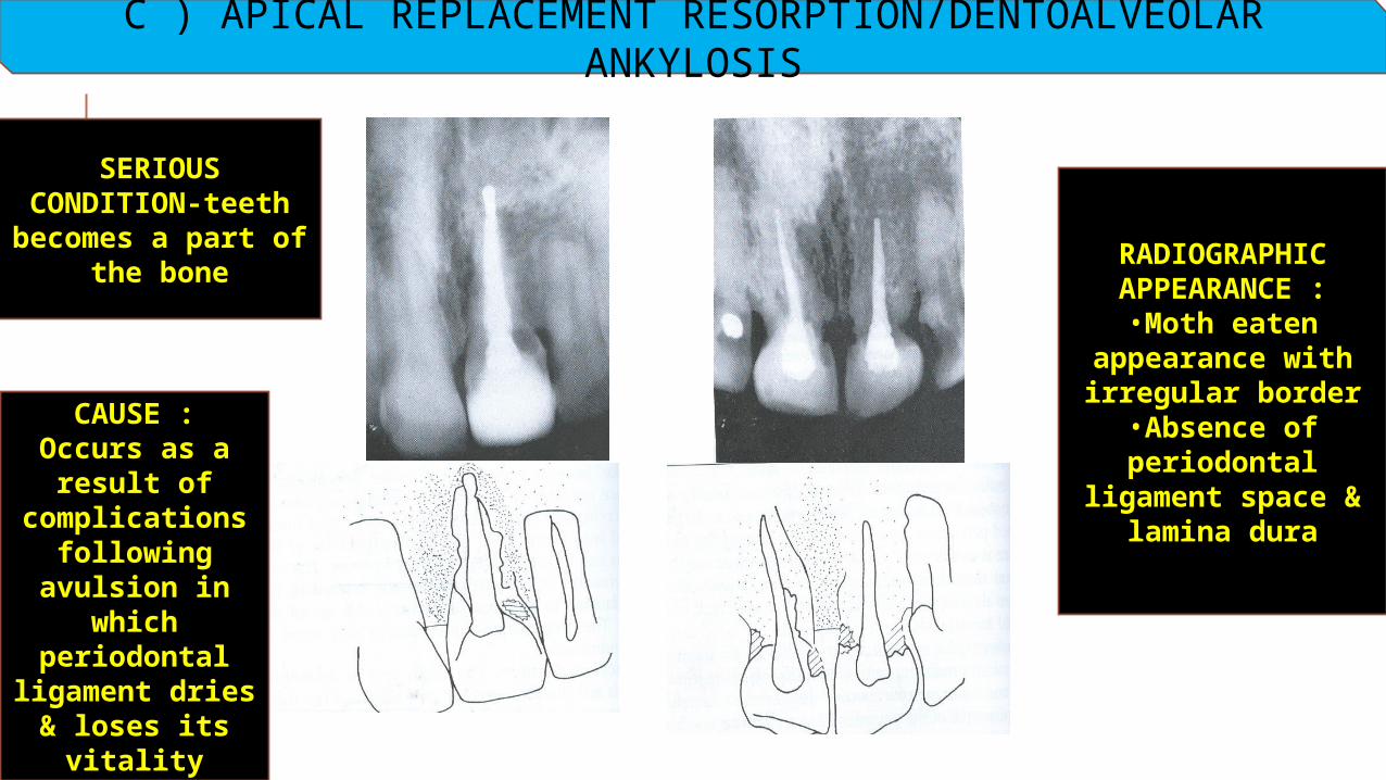
C ) APICAL REPLACEMENT RESORPTION/DENTOALVEOLAR ANKYLOSIS
RADIOGRAPHIC APPEARANCE :
•Moth eaten appearance with irregular border
•Absence of periodontal
ligament space & lamina dura
CAUSE :Occurs as a
result of complications
following avulsion in
which periodontal
ligament dries & loses its
vitality
SERIOUS CONDITION-teeth becomes a part of
the bone
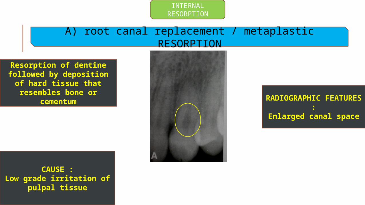
INTERNAL RESORPTION
A) root canal replacement / metaplastic RESORPTION
RADIOGRAPHIC FEATURES :
Enlarged canal space
Resorption of dentine followed by deposition of
hard tissue that resembles bone or
cementum
CAUSE :Low grade irritation of
pulpal tissue
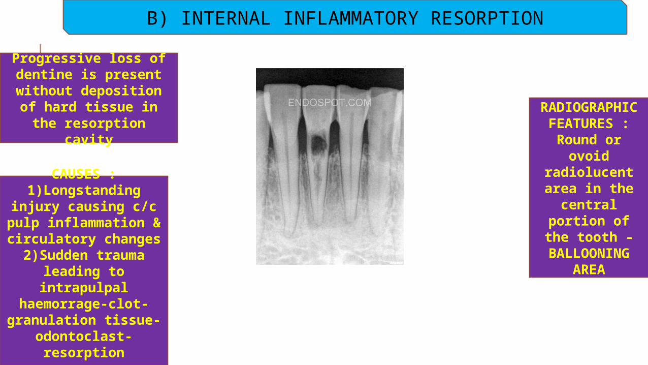
B) INTERNAL INFLAMMATORY RESORPTION
RADIOGRAPHIC FEATURES :
Round or ovoid
radiolucent area in the
central portion of the
tooth – BALLOONING
AREA
Progressive loss of dentine is present
without deposition of hard tissue in the resorption cavity
CAUSES :1)Longstanding
injury causing c/c pulp inflammation & circulatory changes2)Sudden trauma
leading to intrapulpal
haemorrage-clot-granulation tissue-
odontoclast-resorption
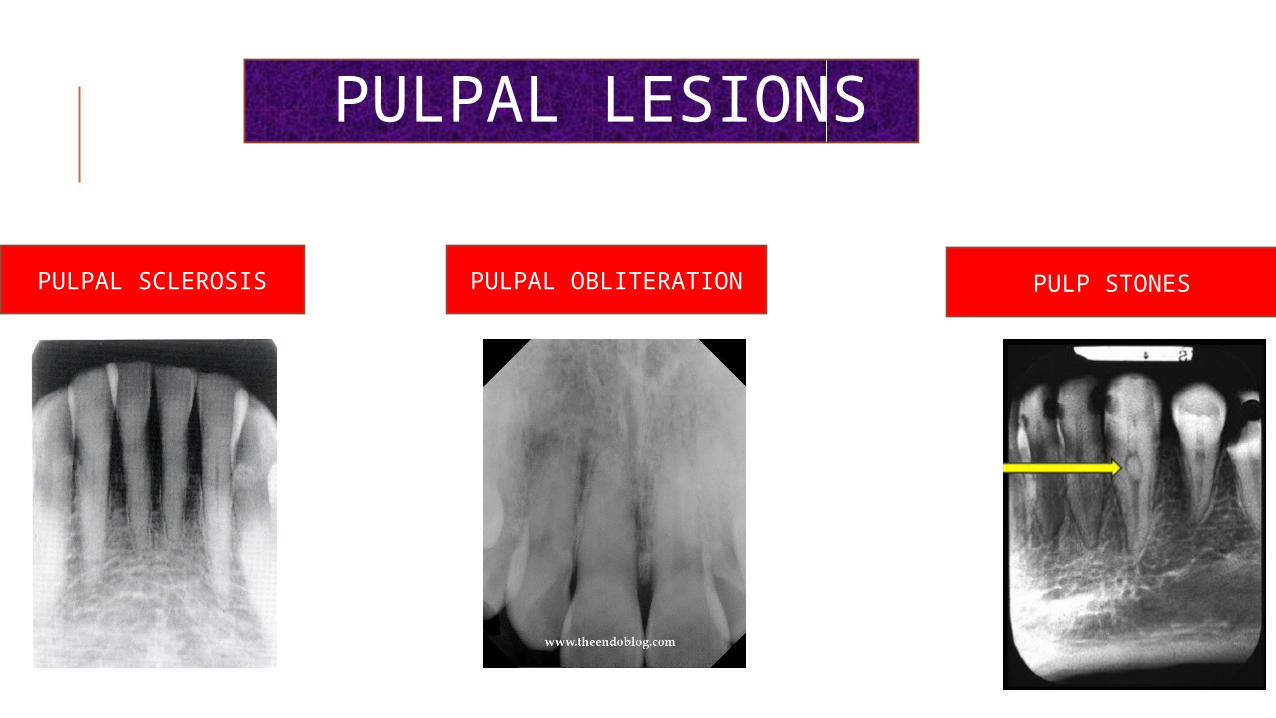
PULPAL LESIONS
PULPAL SCLEROSIS PULPAL OBLITERATION PULP STONES

PERIAPICAL LESIONS
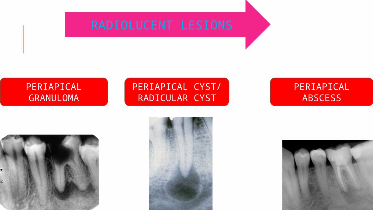
PERIAPICAL GRANULOMA
PERIAPICAL CYST/ RADICULAR CYST
PERIAPICAL ABSCESS
RADIOLUCENT LESIONS
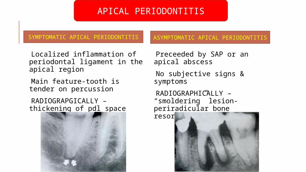
APICAL PERIODONTITIS
Localized inflammation of periodontal ligament in the apical region
Main feature-tooth is tender on percussion
RADIOGRAPGICALLY – thickening of pdl space
Preceeded by SAP or an apical abscess
No subjective signs & symptoms
RADIOGRAPHICALLY – “smoldering” lesion-periradicular bone resorption
SYMPTOMATIC APICAL PERIODONTITIS ASYMPTOMATIC APICAL PERIODONTITIS
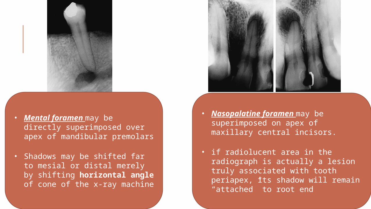
• Mental foramen may be directly superimposed over apex of mandibular premolars
• Shadows may be shifted far to mesial or distal merely by shifting horizontal angle of cone of the x-ray machine
• Nasopalatine foramen may be superimposed on apex of maxillary central incisors.
• if radiolucent area in the radiograph is actually a lesion truly associated with tooth periapex, its shadow will remain “attached” to root end
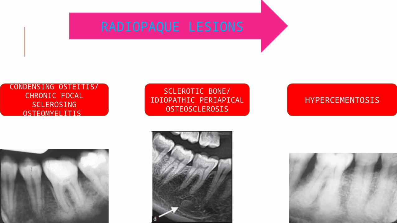
CONDENSING OSTEITIS/ CHRONIC FOCAL
SCLEROSING OSTEOMYELITIS
SCLEROTIC BONE/ IDIOPATHIC PERIAPICAL
OSTEOSCLEROSISHYPERCEMENTOSIS
RADIOPAQUE LESIONS
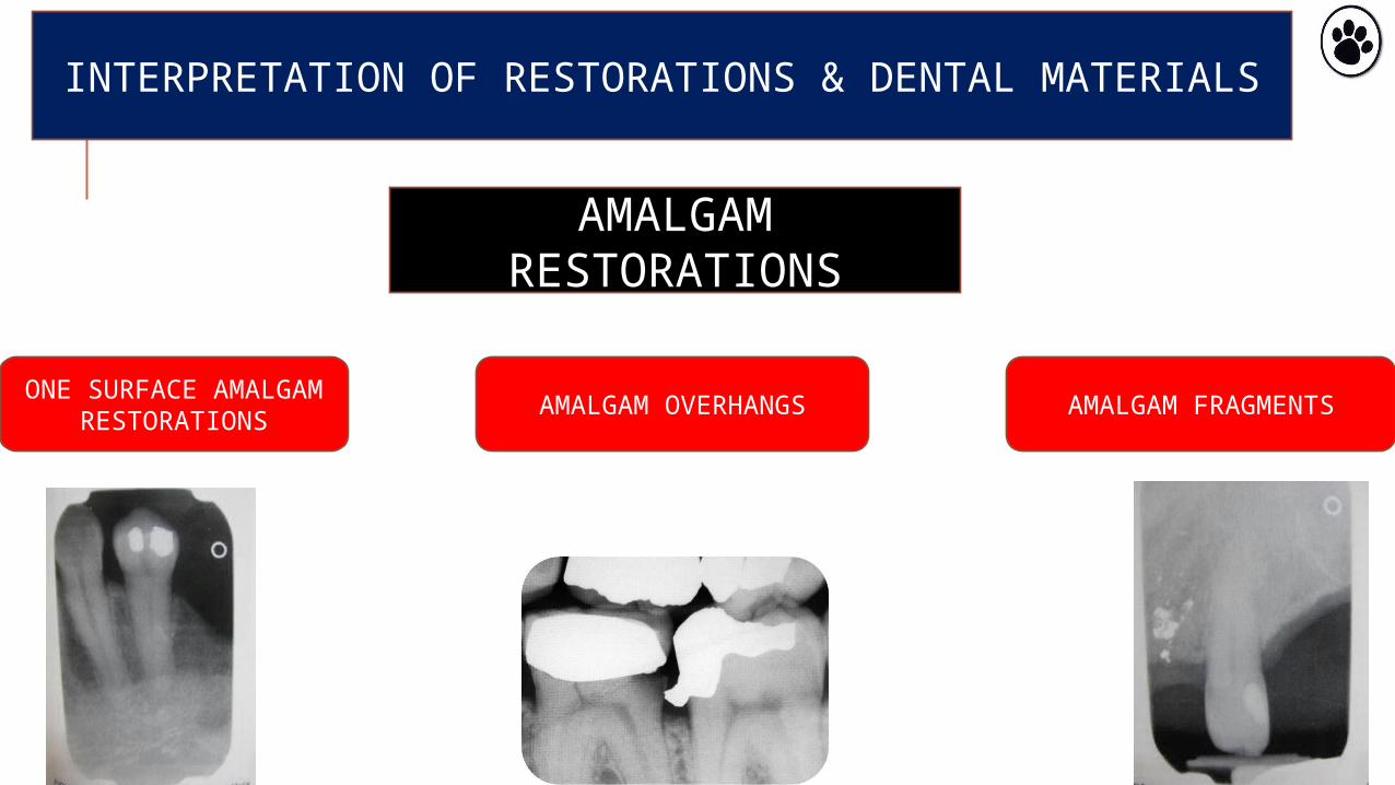
INTERPRETATION OF RESTORATIONS & DENTAL MATERIALS
AMALGAM RESTORATIONS
ONE SURFACE AMALGAM
RESTORATIONSAMALGAM OVERHANGS AMALGAM FRAGMENTS
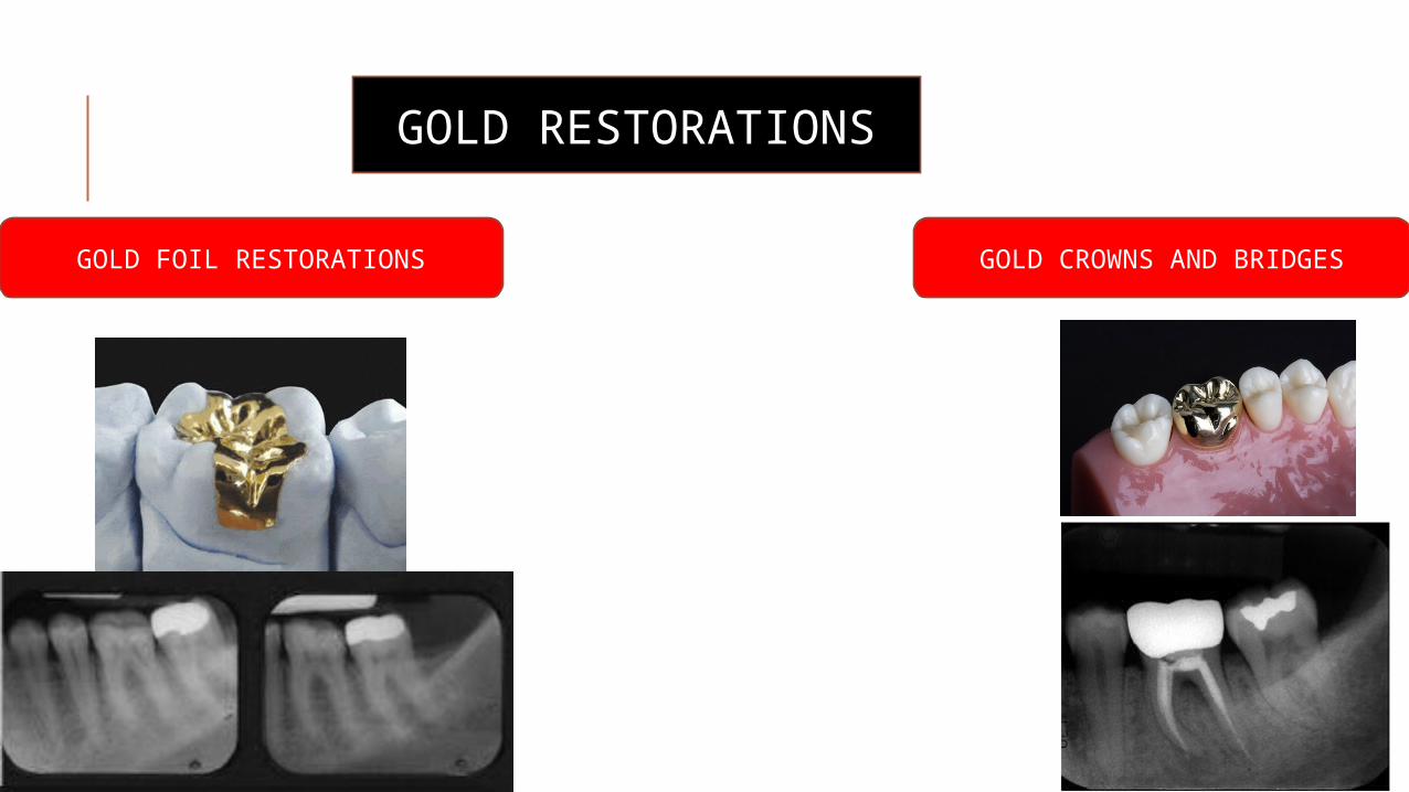
GOLD RESTORATIONS
GOLD FOIL RESTORATIONS GOLD CROWNS AND BRIDGES
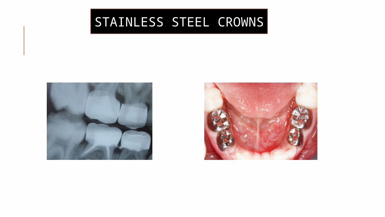
STAINLESS STEEL CROWNS
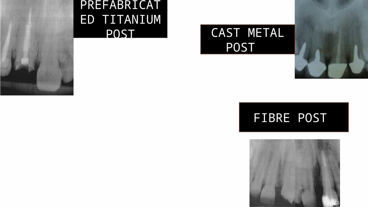
CAST METAL POST
FIBRE POST
PREFABRICATED TITANIUM
POST
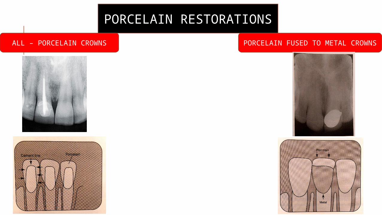
PORCELAIN RESTORATIONS
ALL – PORCELAIN CROWNSPORCELAIN FUSED TO METAL
CROWNS
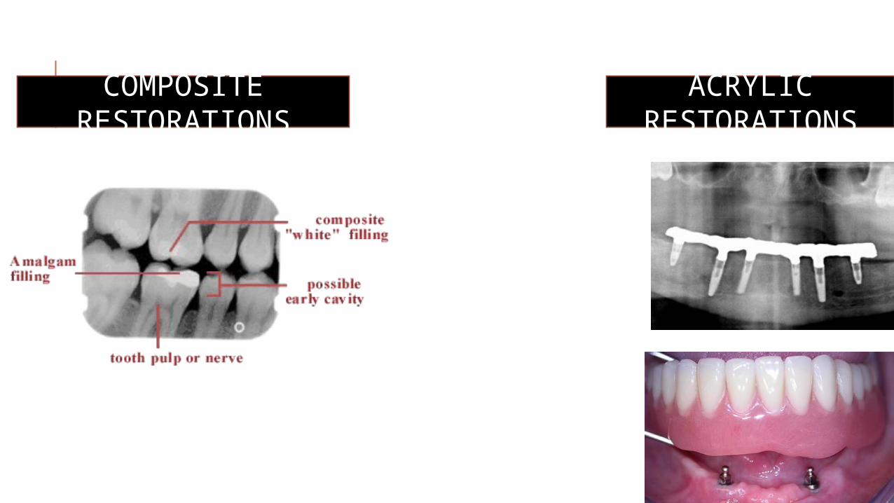
COMPOSITE RESTORATIONS
ACRYLIC RESTORATIONS
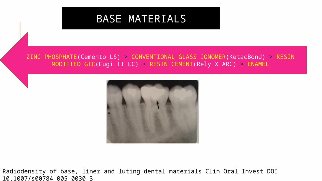
BASE MATERIALS
ZINC PHOSPHATE(Cemento LS) > CONVENTIONAL GLASS IONOMER(KetacBond) > RESIN MODIFIED GIC(Fugi II LC) > RESIN CEMENT(Rely X ARC) > ENAMEL
Radiodensity of base, liner and luting dental materials Clin Oral Invest DOI 10.1007/s00784-005-0030-3
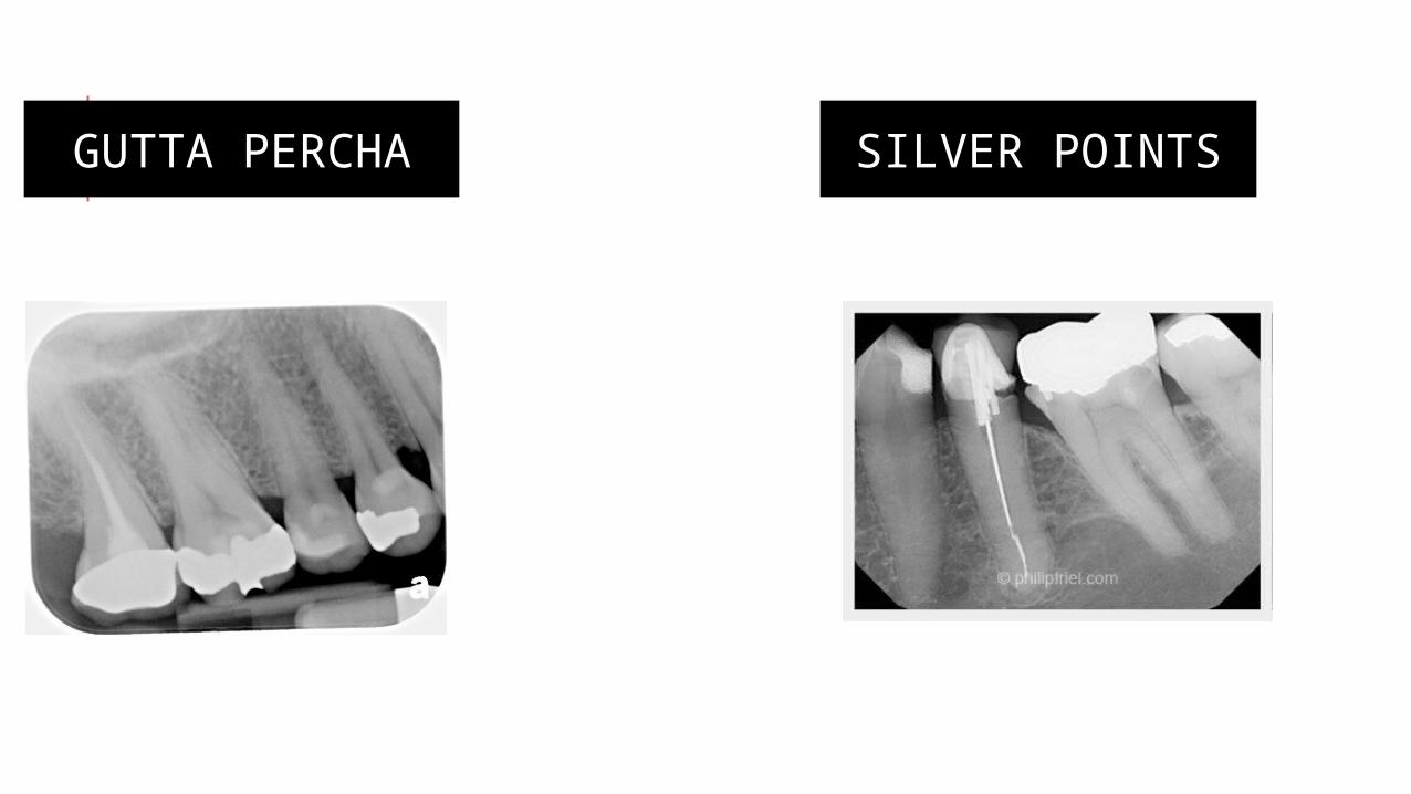
GUTTA PERCHA SILVER POINTS
INTERPRETATION OF ROOT CANAL ANATOMY
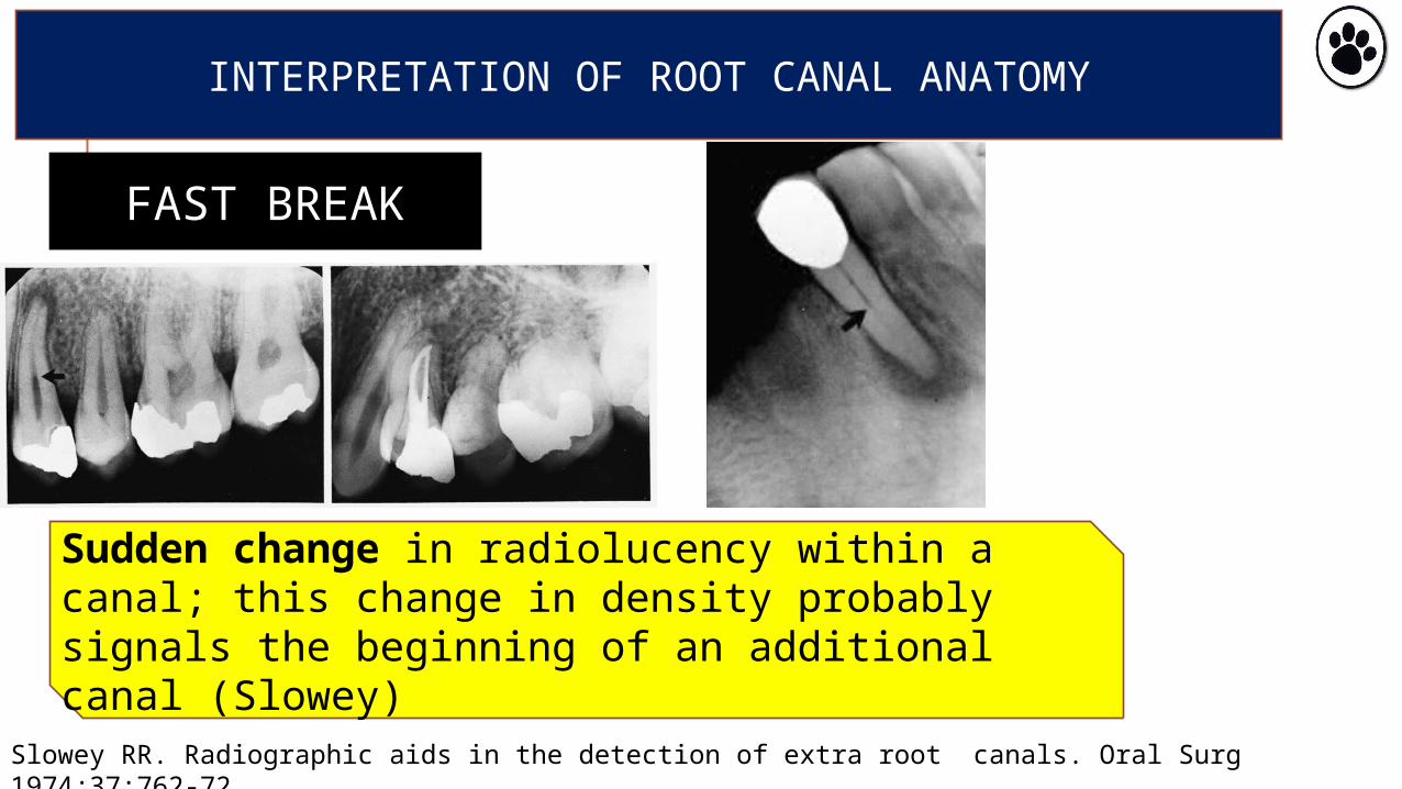
FAST BREAK
Sudden change in radiolucency within a canal; this change in density probably signals the beginning of an additional canal (Slowey)
Slowey RR. Radiographic aids in the detection of extra root canals. Oral Surg 1974;37:762-72
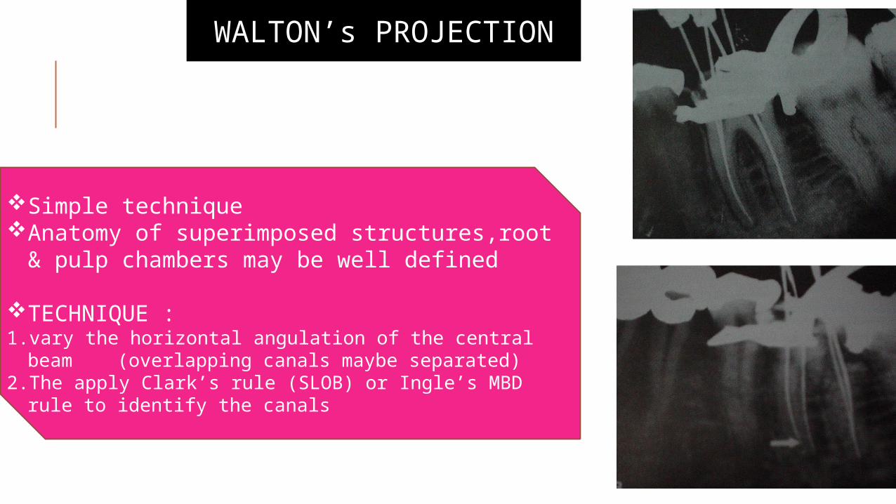
WALTON’s PROJECTION
Simple techniqueAnatomy of superimposed structures,root &
pulp chambers may be well defined
TECHNIQUE : 1. vary the horizontal angulation of the central beam
(overlapping canals maybe separated)2. The apply Clark’s rule (SLOB) or Ingle’s MBD rule to
identify the canals
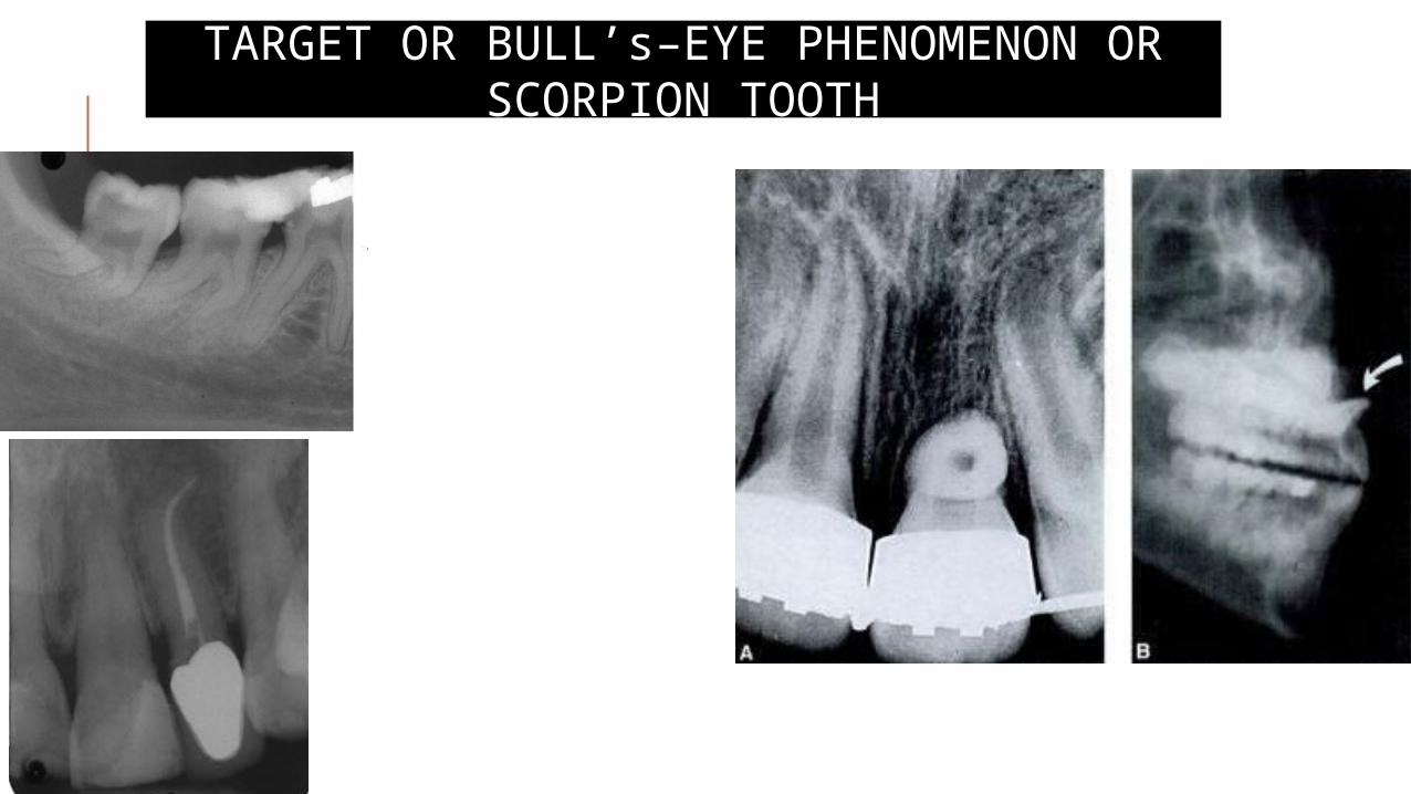
TARGET OR BULL’s–EYE PHENOMENON OR SCORPION TOOTH
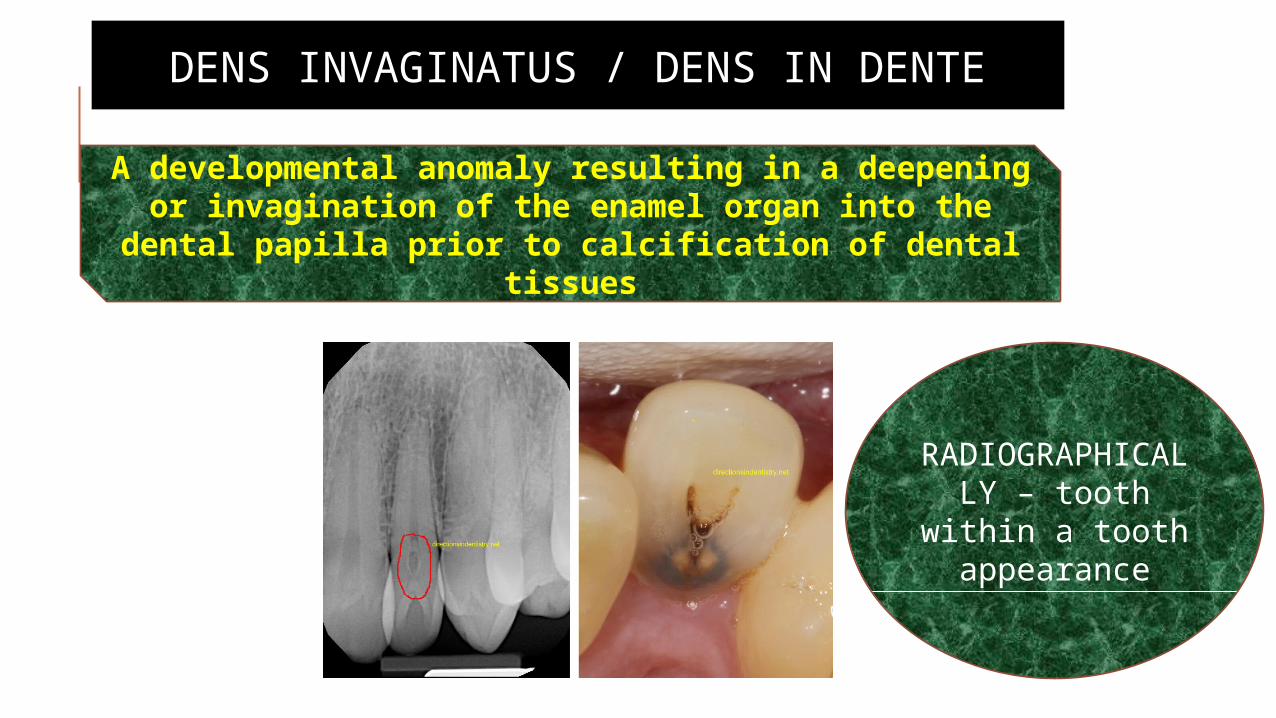
DENS INVAGINATUS / DENS IN DENTE
A developmental anomaly resulting in a deepening or invagination of the enamel organ into the dental
papilla prior to calcification of dental tissues
RADIOGRAPHICALLY – tooth
within a tooth appearance
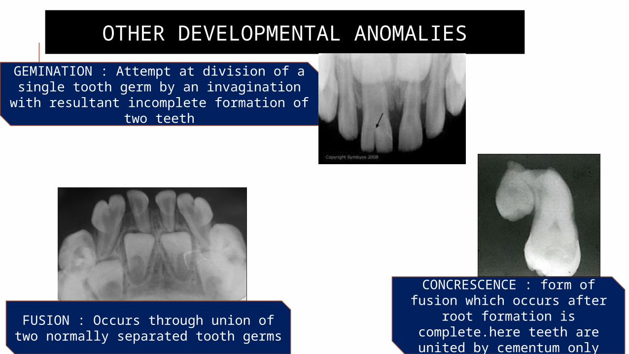
OTHER DEVELOPMENTAL ANOMALIES
GEMINATION : Attempt at division of a single tooth germ by an invagination with resultant
incomplete formation of two teeth
FUSION : Occurs through union of two normally separated tooth germs
CONCRESCENCE : form of fusion which occurs after root formation is complete.here teeth are united
by cementum only
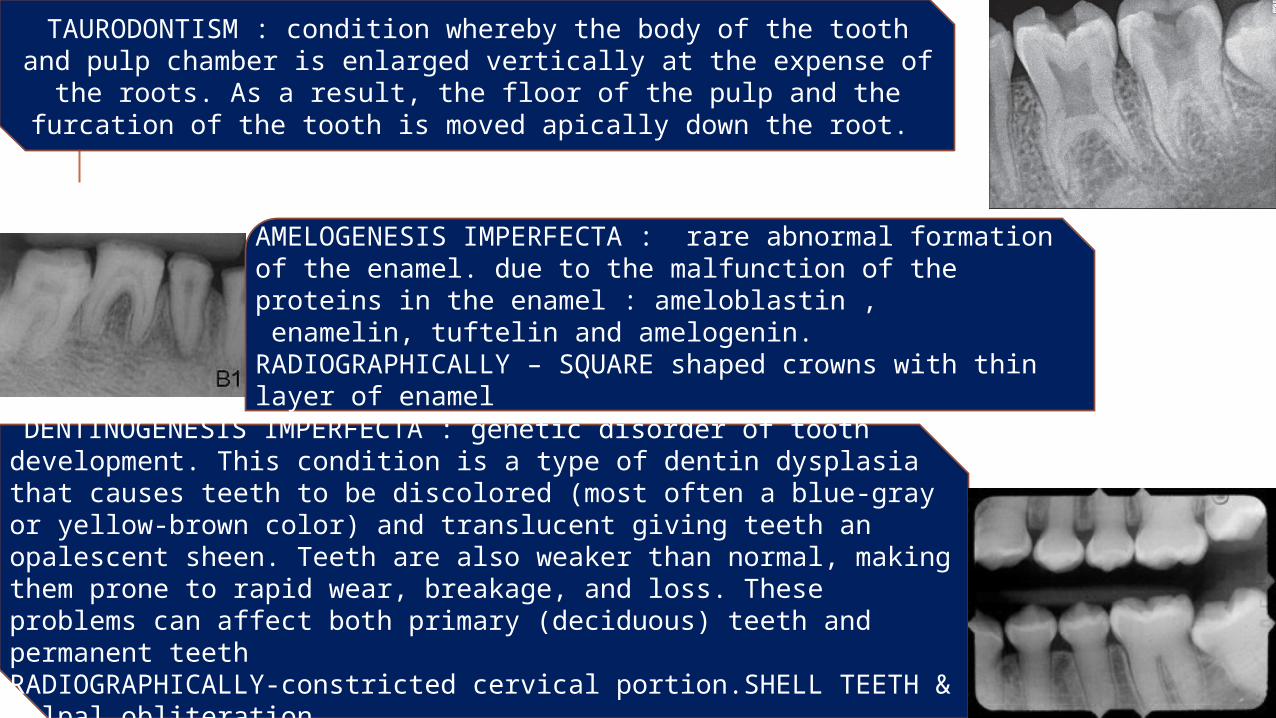
TAURODONTISM : condition whereby the body of the tooth and pulp chamber is enlarged vertically at the expense of the roots. As a
result, the floor of the pulp and the furcation of the tooth is moved apically down the root.
AMELOGENESIS IMPERFECTA : rare abnormal formation of the enamel. due to the malfunction of the proteins in the enamel : ameloblastin , enamelin, tuftelin and amelogenin.RADIOGRAPHICALLY – SQUARE shaped crowns with thin layer of enamel
DENTINOGENESIS IMPERFECTA : genetic disorder of tooth development. This condition is a type of dentin dysplasia that causes teeth to be discolored (most often a blue-gray or yellow-brown color) and translucent giving teeth an opalescent sheen. Teeth are also weaker than normal, making them prone to rapid wear, breakage, and loss. These problems can affect both primary (deciduous) teeth and permanent teethRADIOGRAPHICALLY-constricted cervical portion.SHELL TEETH & pulpal obliteration

REFERENCESDental radiology, Principles & Techniques – Joen M Iannucci, Laura Howerton
Oral Radiology,7th edition – Stuart C White , Michael Pharoah
Textbook of dental & maxillofacial radiology – R. Karjodkar
Endodontics – Ingle
Endodontics-principles & practices- Mahamoud Torabinejad, Richard Walton
Shafer’s textbook of oral pathology,6th edition – R.Rajendran
Dental Trauma Guide – International association of Dental traumatology
Digital Radiography As A Diagnostic Tool In Dentistry-American association of dental maxillofacial radiographic technicians
Dental Root Resorption: A Review of the Literature – Compendium - April 2011, Volume 32, Issue 3