radioactive waste management : engineered barrier systems ... · canisters, buffer, backfill,...
TRANSCRIPT
Engineered Barrier Systems(EBS) in the Context ofthe Entire Safety Case
Radioactive Waste Management
N U C L E A R • E N E R G Y • A G E N C Y
Workshop ProceedingsOxford, United Kingdom25-27 September 2002

Radioactive Waste Management
Engineered Barrier Systems (EBS)in the Context of the Entire Safety Case
Workshop ProceedingsOxford, United Kingdom
25-27 September 2002
In co-operation with theEuropean Commission
and hosted byUnited Kingdom Nirex Limited
© OECD 2003
NUCLEAR ENERGY AGENCYORGANISATION FOR ECONOMIC CO-OPERATION AND DEVELOPMENT

ORGANISATION FOR ECONOMIC CO-OPERATION AND DEVELOPMENT
Pursuant to Article 1 of the Convention signed in Paris on 14th December 1960, and which came into force on30th September 1961, the Organisation for Economic Co-operation and Development (OECD) shall promote policiesdesigned:
− to achieve the highest sustainable economic growth and employment and a rising standard of living inMember countries, while maintaining financial stability, and thus to contribute to the development of theworld economy;
− to contribute to sound economic expansion in Member as well as non-member countries in the process ofeconomic development; and
− to contribute to the expansion of world trade on a multilateral, non-discriminatory basis in accordance withinternational obligations.
The original Member countries of the OECD are Austria, Belgium, Canada, Denmark, France, Germany, Greece,Iceland, Ireland, Italy, Luxembourg, the Netherlands, Norway, Portugal, Spain, Sweden, Switzerland, Turkey, the UnitedKingdom and the United States. The following countries became Members subsequently through accession at the datesindicated hereafter: Japan (28th April 1964), Finland (28th January 1969), Australia (7th June 1971), New Zealand (29thMay 1973), Mexico (18th May 1994), the Czech Republic (21st December 1995), Hungary (7th May 1996), Poland (22ndNovember 1996), Korea (12th December 1996) and the Slovak Republic (14 December 2000). The Commission of theEuropean Communities takes part in the work of the OECD (Article 13 of the OECD Convention).
NUCLEAR ENERGY AGENCY
The OECD Nuclear Energy Agency (NEA) was established on 1st February 1958 under the name of the OEECEuropean Nuclear Energy Agency. It received its present designation on 20th April 1972, when Japan became its firstnon-European full Member. NEA membership today consists of 28 OECD Member countries: Australia, Austria, Belgium,Canada, Czech Republic, Denmark, Finland, France, Germany, Greece, Hungary, Iceland, Ireland, Italy, Japan, Luxembourg,Mexico, the Netherlands, Norway, Portugal, Republic of Korea, Slovak Republic, Spain, Sweden, Switzerland, Turkey, theUnited Kingdom and the United States. The Commission of the European Communities also takes part in the work of theAgency.
The mission of the NEA is:
− to assist its Member countries in maintaining and further developing, through international co-operation, thescientific, technological and legal bases required for a safe, environmentally friendly and economical use ofnuclear energy for peaceful purposes, as well as
− to provide authoritative assessments and to forge common understandings on key issues, as input togovernment decisions on nuclear energy policy and to broader OECD policy analyses in areas such as energyand sustainable development.
Specific areas of competence of the NEA include safety and regulation of nuclear activities, radioactive wastemanagement, radiological protection, nuclear science, economic and technical analyses of the nuclear fuel cycle, nuclear lawand liability, and public information. The NEA Data Bank provides nuclear data and computer program services forparticipating countries.
In these and related tasks, the NEA works in close collaboration with the International Atomic Energy Agency inVienna, with which it has a Co-operation Agreement, as well as with other international organisations in the nuclear field.
© OECD 2003Permission to reproduce a portion of this work for non-commercial purposes or classroom use should be obtained through theCentre français d’exploitation du droit de copie (CCF), 20, rue des Grands-Augustins, 75006 Paris, France, Tel. (33-1) 44 0747 70, Fax (33-1) 46 34 67 19, for every country except the United States. In the United States permission should be obtainedthrough the Copyright Clearance Center, Customer Service, (508)750-8400, 222 Rosewood Drive, Danvers, MA 01923,USA, or CCC Online: http://www.copyright.com/. All other applications for permission to reproduce or translate all or partof this book should be made to OECD Publications, 2, rue André-Pascal, 75775 Paris Cedex 16, France.

3
EXECUTIVE SUMMARY
Repositories for the disposal of radioactive waste generally rely on a multi-barrier system toisolate the waste from the biosphere. This multi-barrier principle creates an overall system robustnessthat enhances confidence that the waste will be successfully contained.
The multi-barrier system typically comprises the natural (geological) barrier provided by therepository host rock and its surroundings, and an engineered barrier system (EBS). Ensuring that anEBS will perform its desired functions requires integration of site-characterisation data, data on wasteproperties, data on engineering properties of potential barrier materials, in situ and laboratory testing,and modelling.
In 2002, the Integration Group for the Safety Case (IGSC) of the Nuclear Energy Agency(NEA) wished to reassess the need for a project to develop a greater understanding of how to achievethe necessary integration for the successful design, construction, testing, modelling and performanceassessment of engineered barrier systems. To this end a workshop was held under the joint auspices ofthe EC and the NEA, hosted by United Kingdom Nirex Limited (Nirex), at Keble College, Oxford on25-27 September 2002. The workshop was attended by 40 delegates representing 15 countries and theNEA-EC sponsors. The workshop was intended to provide a status report on engineered barriersystems in various national programmes, to establish the value to member countries of a project onEBS and, if supported, to define the project’s scope, timetable and modus operandi. In particular, theworkshop was to consider the need to reduce the number of subsequent workshops, as compared witha previous proposal for a project on EBS. This report summarises the joint NEA-EC workshop entitled“Engineered Barrier Systems in the Context of the Entire Safety Case”.
It was agreed that there was strong support amongst the many countries represented forcontinued international co-operation between the NEA and the EC on the NEA project on EBS, andthat it was important to present as an overall outcome an account of how EBS design is developed,justified and implemented using state-of-the-art knowledge. It was also agreed that the project wouldbe best served by a sequence of further workshops as follows:
Workshop 1 Design Requirements and Constraints.
Workshop 2 Process Issues:
• Thermal management and analysis.
• Alteration of non-metallic barriers and evolution of solution chemistry.
• Radionuclide release and transport.
Workshop 3 Role of Performance Assessment and Process Models.
Workshop 4 Design Confirmation and Demonstration.
This sequence of workshops will lead the NEA-EC EBS project through an optimisationcycle of the type discussed at the workshop.

4
Acknowledgements
On behalf of all participants, the NEA wishes to express its gratitude to United KingdomNirex Limited, which hosted the workshop in Oxford, as well as to the EC for its co-operation in thisjoint EC/NEA project.
Special thanks are also due to:
• The members of the Workshop Programme Committee1 who structured and conductedthe workshop.
• David Bennett, Galson Sciences Limited (United Kingdom) who helped the Secretariatand the programme committee in drafting the workshop synthesis.
• The working group chairpersons and rapporteurs who led and summarised the debatesthat took place in the five working groups.
• The speakers for their interesting and stimulating presentations and all participants fortheir active and constructive contribution.
1. Members of the committee were: Jesus Alonso (ENRESA, Spain), Richard Beauheim (SNL, USDOE-
WIPP, USA), Alan Hooper (UK Nirex Limited, UK), Bob MacKinnon (SNL, US DOE-YMP, USA),Henning von Maravic (EC), Frédéric Plas (Andra, France), Patrik Sellin (SKB, Sweden), Oïvind Töverud(SKI, Sweden), Frank Wong (US DOE-YMP, USA), Hiroyuki Umeki (NUMO, Japan) and Sylvie Voinis(OECD, NEA, France).
5
TABLE OF CONTENTS
EXECUTIVE SUMMARY ................................................................................................................ 3
1. INTRODUCTION....................................................................................................................... 7
2. WORKSHOP OBJECTIVES AND AGENDA........................................................................... 11
3. EBS FUNCTION, DESIGN, CHARACTERISATION AND ASSESSMENT.......................... 13
3.1 EBS Function, Design and Characterisation .................................................................... 133.2 EBS Modelling and Performance Assessment ................................................................. 16
4. WORKING GROUP SESSIONS................................................................................................ 19
4.1 Working Group A: Design Criteria and Construction...................................................... 194.2 Working Group B: Thermo-Hydro-Mechanical (THM) Processes.................................. 204.3 Working Group C: Geochemical Processes ..................................................................... 224.4 Working Group D: Radionuclide Release and Migration ................................................ 24
5. WORKSHOP CONCLUSIONS.................................................................................................. 29
5.1 Technical Issues................................................................................................................ 295.2 Programmatic Issues......................................................................................................... 31
6. REFERENCES............................................................................................................................ 33
Appendix A: WORKSHOP AGENDA ............................................................................................. 35
Appendix B: PAPERS PRESENTED TO THE WORKSHOP......................................................... 39
Managing Design Requirements for a Repository in Crystalline RockTimo Äikas (Posiva Oy, Finland) ....................................................................................................... 41
Managing Design Requirements of the French HLLW Programme in Clay MediaJean-Michel Hoorelbeke, Stefan Mayer and Frédéric Plas (Andra, France) ................................... 43
Closure Concept for the Morsleben LLW Repository for Radioactive Waste Designof Drift Seals in a Former Salt MineRalf Mauke, Jürgen Wollrath (BfS, Germany) and Nina Müller-Hoeppe (DBE, Germany).............. 51
CROP – A Project for Comparative Description of National Concepts for Disposalof Radioactive WasteRoland Pusch (Geodevelopment AB, Sweden) and Christer Svemar (SKB, Sweden) ........................ 65
6
The Role of the EBS in Demonstrating Post-closure Safety of the ProposedYucca Mountain RepositoryRobert J. MacKinnon (SNL, US) ........................................................................................................ 81
Engineered Barriers System Modelling and Performance Assessment in SAFIR 2Xavier Sillen, Jan Marivoet (SCK•CEN, Belgium), Jean-Paul Boyazis, Philippe Lalieux,Peter De Preter and Johan Bel (ONDRAF/NIRAS, Belgium) ............................................................ 93
EBS Modelling and Performance Assessment from H12: Results Conclusionsand Future PrioritiesHiroyuki Umeki, Hiroyoshi Ueda, Morimasa Naito (NUMO, Japan) and Masao Shiotsuki(JNC, Japan)....................................................................................................................................... 99
On-going Activities of the EC Project “BENIPA” – Current Status, Key Issues and AchievementsJesús Alonso (ENRESA, Spain) .......................................................................................................... 115
Appendix C: Remit and Composition of Working Groups............................................................... 129Working Groups Remit ............................................................................................... 131Working Groups Composition .................................................................................... 141
Appendix D: List of Participants....................................................................................................... 143
List of Figures
Figure 1. The development process for the Finnish disposal system.......................................... 14
Figure 2. One of the current French design options for the disposal of vitrifiedhigh-level waste, including a bentonite buffer ............................................................ 15
Figure 3. Example of a model of water saturation in the excavation-disturbed zone (EDZ)from the EC CROP Project ......................................................................................... 16
Figure 4. The current conceptual design for the EBS at the proposedYucca Mountain repository ......................................................................................... 17
Figure 5. Example grid from a deterministic model of radionuclide transport in thenear-field developed as part of the EC BENIPA Project............................................. 18
Figure 6. Steps in the development of a disposal system design ................................................ 20
List of Tables
Table 1. Geochemical issues considered by Working Group C ................................................ 23
Table 2. “Internal” and “External” Components of the EBS25 ................................................ 25
Table 3. Geochemical and radionuclide transport issues relevant to the InternalEBS Components ........................................................................................................ 26
Table 4. Processes influencing mass transport in the External EBS Components ................... 27
Table 5. Common issues to be considered at future workshops ............................................... 28
Table 6. Aims of proposed future EBS project workshops ....................................................... 32

7
1. INTRODUCTION
Repositories for disposal of radioactive waste generally rely on a multi-barrier system toisolate the waste from the biosphere. This multi-barrier principle creates an overall system robustnessthat enhances confidence that the waste will be successfully contained. The multi-barrier systemtypically comprises the natural (geological) barrier provided by the repository host rock and itssurroundings, and an engineered barrier system (EBS).
An EBS may itself comprise a variety of components, such as the waste form, wastecanisters, buffer, backfill, seals, and plugs. The general purpose of an EBS is to prevent and/or delaythe release of radionuclides from the waste to the repository host rock, at least during the first severalhundred years after repository closure when the fission-product content is high, and where they mightbe mobilised by natural groundwater flow. In many disposal concepts, the EBS, operating under stableand favourable geosphere conditions, is designed to contain most of the radionuclides for much longerperiods.
The specific role that an EBS is designed to play in a particular waste disposal concept isdependent on the conditions that are expected (or considered possible) to occur over the period ofregulatory interest, and the anticipated performance of the natural geological barrier. To be effective,an EBS must be tailored to the specific environment in which it is to function. Consideration must begiven to factors such as the heat that will be produced by the waste, the pH and redox conditions thatare expected, the expected groundwater flux, the local groundwater chemistry, possible interactionsamong different materials in the waste and EBS, the mechanical behaviour of the host rock afterrepository closure, and the evolution of conditions over time. Ensuring that an EBS will perform itsdesired functions requires an integration, often iterative, of site characterisation data, data on wasteproperties, data on engineering properties of potential barrier materials, “in situ and laboratorytesting”, and modelling.
In 2002, the Integration Group for the Safety Case (IGSC) of the Nuclear Energy Agency(NEA) wished to assess the need for a project to develop a greater understanding of how to achieve thenecessary integration for successful design, construction, testing, modelling, and performanceassessment of engineered barrier systems.
To this end a workshop was held under the joint auspices of the EC and the NEA, hosted byUnited Kingdom Nirex Limited (Nirex), at Keble College, Oxford on 25-27 September 2002. Theworkshop was attended by 40 delegates representing 15 countries and the EC/NEA sponsors. It wasintended to provide a status report on engineered barrier systems in various national programmes, toestablish the value to member countries of a project on the EBS and, if supported, to define its outlinescope, timetable and modus operandi. In particular, the workshop was to consider the need to reducethe number of subsequent workshops, as compared with a previous proposal for a project on the EBS.This report summarises the joint NEA-EC workshop entitled “Engineered Barrier Systems in theContext of the Entire Safety Case”.

8
EBS performance can be considered according to four main themes:
• Engineering design perspective, e.g., how can a component be (re-)engineered toimprove performance or ease of modelling?
• Characterisation perspective, e.g., how can properties of the EBS and the conditionsunder which it must function be measured or otherwise characterised?
• Modelling perspective, e.g., how well can the relevant processes be modelled?
• Performance assessment perspective, e.g., how can the performance of the EBS and/orits components be evaluated under a wide range of conditions?
These themes formed the basis for the discussions at the workshop, which was intended topromote interaction and collaboration among experts responsible for engineering design,characterisation, modelling, and performance assessment of engineered barrier systems. The workshopalso examined interactions between the EBS and the near-field host rock as well as radionuclidereleases from the near-field to the far-field.
In organising the workshop, the IGSC intended to develop a greater understanding of how toachieve the integration needed for successful design, construction, testing, modelling, and performanceassessment of engineered barrier systems, and to clarify the role that an EBS can play in the overallsafety case for a repository. A safety case is a collection of arguments, at a given stage of repositorydevelopment, in support of the long-term safety of the repository. A safety case includes thequantitative results derived from performance assessment modelling, but also considers aspects ofbarrier performance that are difficult to quantify but can qualitatively be shown to enhance therobustness of the system.
To set the context for the Oxford workshop, the EC provided support for the production of astate-of–the-art report based on responses to an NEA questionnaire on the EBS. The state-of-the-artreport thus developed (NEA-EC 2003) is an important early product from the EBS project. Toevaluate progress during the EBS project, it is intended to develop a further state-of-the-art report atthe end of the project, in 2006.
Recognising the diversity in engineered barrier systems in various national programmes, asshown by the recent state-of-the-art report (NEA-EC 2003), the project is seeking to share knowledgeand experience about the integration of EBS functions, engineering design, characterisation, modellingand performance evaluation in order to understand and document the state of the art, and to identifythe key areas of uncertainty that need to be addressed. Specific objectives are to:
• Understand the relationship between the functions to be served by the EBS and itsdesign in different repository contexts.
• Compare different methods of characterising EBS properties.
• Compare different approaches to modelling of the EBS.
• Compare different means of evaluating EBS performance.
• Compare different engineering approaches to similar problems.
• Compare techniques for evaluating, characterising, and modelling interactions betweenthe EBS and near-field host rock.

9
This report is structured as follows:
• Section 2 summarises the objectives and components of the workshop.
• Section 3 summarises the presentations and discussions on the opening day of theworkshop, regarding the function, design, characterisation and assessment of the EBS.
• Section 4 summarises results from four working group sessions, which were held duringthe second and third days of the workshop.
• Section 5 presents the overall conclusions from the workshop.
• Section 6 provides a list of references.


11
2. WORKSHOP OBJECTIVES AND AGENDA
The workshop Agenda is contained in Appendix A. The workshop began with welcomingaddresses from Sylvie Voinis (NEA), Henning von Maravic (EC) and Alan Hooper (Nirex). HiroyukiUmeki (NUMO) then described the background to the NEA IGSC-EBS Project (Section 1), and thespecific objectives of the first workshop as follows:
• To consider a balanced range of waste management options and disposal concepts, andto consider a range of repository host rock media.
• To focus on the state-of-the-art regarding EBS design, characterisation, implementation,understanding and assessment, in order to obtain a general picture of the status of eachnational waste management programme.
• To design the outlines of a programme for the IGSC-EBS Project and, more specifically,to arrive at an appropriate number of subsequent workshops.
David Bennett (GSL) then summarised the responses from the organisations participating inthe IGSC-EBS Project to the NEA’s EBS questionnaire (see Section 5.1 and NEA-EC 2003). The firstday of the workshop then continued with presentations (see Appendix B) on two main themes:
(i) EBS function, design and characterisation.
(ii) EBS modelling and performance assessment.
The second day and part of the morning on the third day were devoted to working groupsessions. Four working groups (see Appendix C) were convened to consider the following topics:
Working Group A: Design Criteria and Construction.
Working Group B: Thermo-Hydro-Mechanical (THM) Processes.
Working Group C: Geochemical Processes.
Working Group D: Radionuclide Release and Migration.
The objectives of each working group were to identify relevant issues that it might bepractical to address within an international project, and to develop proposals for subsequent workshopsto address key issues.
The third day of the workshop continued with a plenary session, at which the results of theworking groups were presented to the full range of participants. This was followed by a meeting of theProject Steering Committee, at which the future organisation of the IGSC-EBS Project was discussed.A final plenary session was held to discuss the outcomes of the workshop, which were summarised byAlan Hooper and David Bennett.

13
3. EBS FUNCTION, DESIGN, CHARACTERISATION AND ASSESSMENT
The following sections summarise the contents and main conclusions of the papers presentedto the workshop on the first day. The papers themselves are contained in Appendix B.
3.1 EBS Function, Design and Characterisation
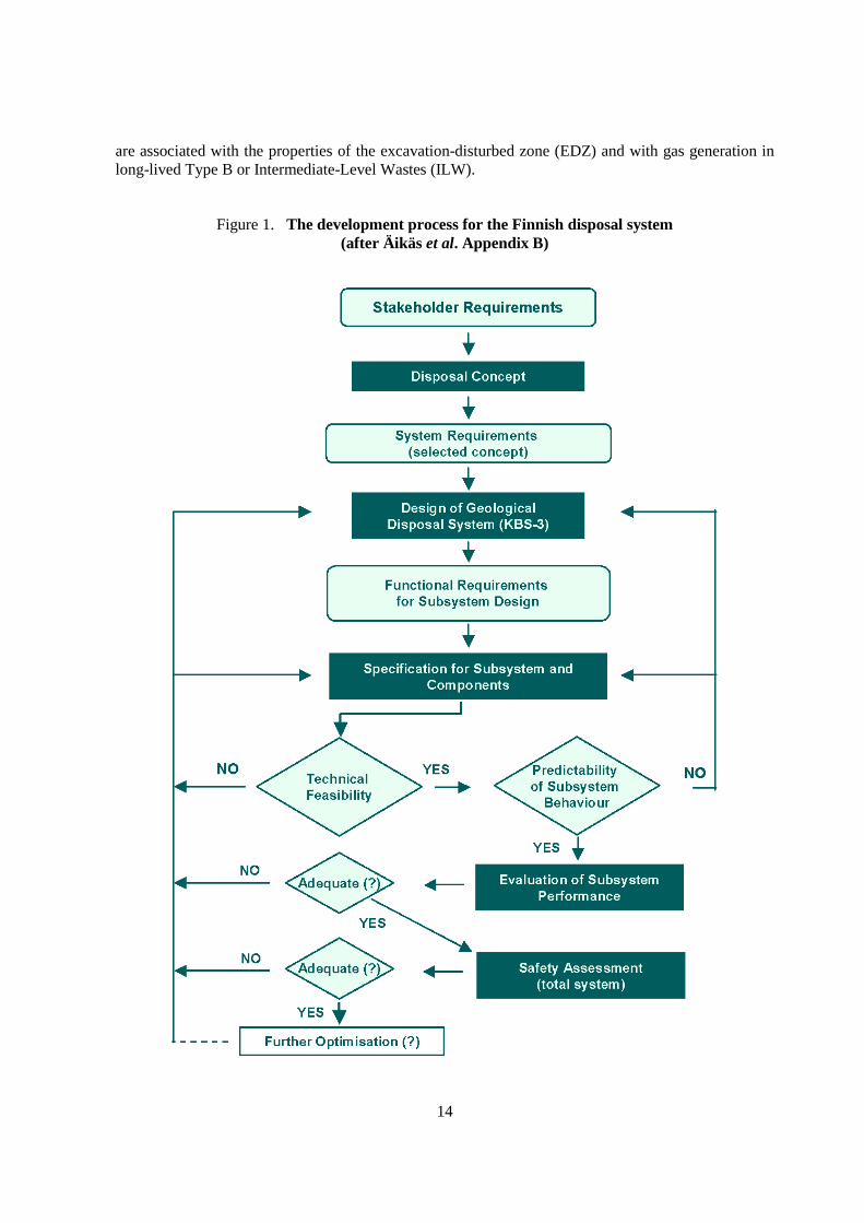
Timo Äikäs (POSIVA) described the Finnish experience and the various types of constraintsand requirements that can affect the design of a repository situated in crystalline rock. An iterativescheme for repository development, or “optimisation cycle”, was presented (Figure 1). The schemedepicted in Figure 1 is a development of earlier schemes (e.g., Bennett et al. 1998; JNC 2000;POSIVA 2000), enhanced to place greater emphasis on the role of demonstration experiments. Theconcept of “requirements management” was described. It was emphasised that systematicconsideration of requirements can help to:
• Improve disposal system understanding.
• Increase and maintain transparency, traceability and clarity regarding:− The treatment of a comprehensive set of requirements.− The justification of requirements.− The verification of requirements.− Design change control.
• Enhance stakeholder dialogue.
• Identify research needs and integrate different disciplines.
• Prioritise technical developments on significant system components.
• Recognise “available design space” and identify room for optimisation.
The need for the production of clear documentation was also emphasised in order that thatfuture generations operating the repository and after its closure understand what was originallyintended in terms of repository design and performance.
Frederic Plas (Andra) summarised French regulatory constraints on radioactive wastedisposal, particularly those constraints relevant to the EBS, and then described Andra’s current designconcepts for a repository in clay host rocks (e.g., Figure 2). Results from Andra’s first safetyassessment, which have been documented in the “Dossier Argile 2001”, were presented, and generalconclusions and perspectives discussed. It was emphasised that the EBS components have a primaryrole in waste containment during operational phase and during the post-closure phase until from 1 000(e.g. vitrified waste) to 10 000 years (case of spent fuel) although the fabrication defects according tothe large amount of waste packages need to be taken into account in the safety analysis. The choice ofpractical conditions for the retrievability of the waste packages may provide a significant additionalconstraint on repository and EBS designs. It was also suggested that simpler designs might help tominimise interactions between EBS materials, and that potentially significant remaining uncertainties
14
are associated with the properties of the excavation-disturbed zone (EDZ) and with gas generation inlong-lived Type B or Intermediate-Level Wastes (ILW).
Figure 1. The development process for the Finnish disposal system(after Äikäs et al. Appendix B)

15
Figure 2. One of the current French design options for the disposal of vitrified high-level waste,including a bentonite buffer (after Plas et al. Appendix B)
The importance of demonstration experiments to developing a successful and convincingsafety case was again highlighted, as was the need for progressive improvement in understandingsystem behaviour, which enables otherwise overly conservative design requirements to be relaxed(optimised).
Nina Müller-Hoeppe (DBE) and Ralphe Mauke (BFS) presented a paper that discussed EBSdesign requirements for a repository in a salt host rock. They noted that design of the Morsleben driftseals necessitated a comprehensive analysis of site-specific information, an extensive investigation ofthe properties of the salt-concrete EBS material, and consideration of information from long-termsafety assessment. These considerations lead to a simple and robust design for the drift seals and apracticable approach for demonstrating compliance with relevant requirements. Development of theEBS concept for the Morsleben facility is scheduled to be completed in 2003, and this will be followedby initiation of a licensing procedure.
Roland Pusch (Geodevelopment AB) presented a summary of the EC Cluster RepositoryProject (CROP). CROP is considering aspects of repository design and construction, theinstrumentation of Underground Research Laboratory (URL) experiments, and the testing oftheoretical models. In particular, the CROP Project is focusing on the buffer, backfill and seals, andtheir interaction with the EDZ. An example of some of the modelling work performed during theCROP project is illustrated in Figure 3. The presentation identified several technical issues wherepotentially significant uncertainties remain including the properties of the EDZ. In the discussion

16
following the paper it was agreed that the IGSC-EBS Project is broader in scope than the EC CROPProject, as the former involves a wider range of countries and disposal concepts, and also because it isconsidering the full range of engineered barriers. It was agreed that because of its nature and scope, itis both possible and appropriate for the IGSC-EBS Project to take a more strategic view thanindividual EC research projects. The NEA and EC projects are complementary and it was agreed thatit would be beneficial to ensure efficient transfer of information between them.
Figure 3. Example of a model of water saturation in the excavation-disturbed zone (EDZ)from the EC CROP Project (after Pusch and Svemar Appendix B)
Following the presentations in this section of the workshop, discussions amongst theworkshop participants centred on the requirement for, and nature of, the iterative process described inthe Finnish paper, and on the need for the requirements of the EBS to be clearly identified and forconstraints on EBS design to be clearly and traceably documented.
3.2 EBS Modelling and Performance Assessment
Robert MacKinnon (SNL) described the role of the EBS in demonstrating post-closure safetyof the proposed Yucca Mountain repository. The paper encompassed key repository designassumptions and requirements, an overview of the proposed Yucca Mountain repository and EBS(Figure 4), discussion of EBS processes and models, and the approach to the post-closure safety case.The Yucca Mountain EBS is designed to provide defence in depth and operational flexibility,particularly with regard to the emplacement of various heat-generating wastes streams. Like severalother national programmes, the Yucca Mountain Project is taking an iterative approach to design. Itwas emphasised that a disposal programme needs to be sufficiently mature and to have conductedseveral iterations in order that modelling tools are sufficiently developed to inform design choicesmeaningfully.

17
Jean-Paul Boyazis (Ondraf/Niras) and Xavier Sillen (SCK•CEN) described the approachestaken in the recent Belgian SAFIR 2 state-of-the-art report concerning technical and scientific aspectsof high-level waste (HLW) and ILW disposal in poorly indurated clays. For a repository in a clay hostrock, such as the Boom Clay, the contribution of the EBS to the overall performance of the disposalsystem is minor when considering the normal evolution scenario.
Figure 4. The current conceptual design for the EBS at the proposed Yucca Mountainrepository (after MacKinnon Appendix B)
This is because the radionuclide travel time in the buffer (the EBS component that hindersradionuclide migration most efficiently) is much shorter than in the host rock. However, the propertiesof the EBS can be of paramount importance to the overall safety of the repository in altered evolutionscenarios in which the host rock barrier is breached, such as those involving poor repository sealing orhuman intrusion. For such scenarios, key issues relate to the hydraulic / mechanical properties of thebuffer, the waste form dissolution rate and the canister lifetime. The EBS also plays an important roleduring the operational phase. The main conclusions from SAFIR 2 include increased confidence in thesuitability of the Belgian Boom Clay to act as an effective barrier to radionuclide migration. In thepost-SAFIR 2 era, the Belgian programme is working to derive a new EBS design by moresystematically linking barrier design to safety functions, and by tailoring EBS design to the propertiesand characteristics of the host rock.
Hiroyuki Umeki (NUMO) described results and conclusions from the EBS modelling andperformance assessment studies that supported the recent Japanese H12 report (JNC 2000). H12evaluated the long-term safety of a Japanese repository concept at the generic stage using integratedperformance assessment methods. In the H12 evaluation, considerable emphasis was placed on theperformance of the near-field. In future stages of the Japanese programme, the engineered barriers willbe optimised, site-specific geological features will be characterised, and understanding of safety-relevant phenomena will continue to be enhanced in order to allow more realistic modelling. It is alsointended to create closer links between repository design, site characterisation and performanceassessment, to conduct a range of technical studies on the EBS, and to further enhance performanceassessment methods to account for spatial heterogeneity, groundwater flow through the EDZ, and thegeometric complexity and effects of multiple radionuclide sources within the repository.
18
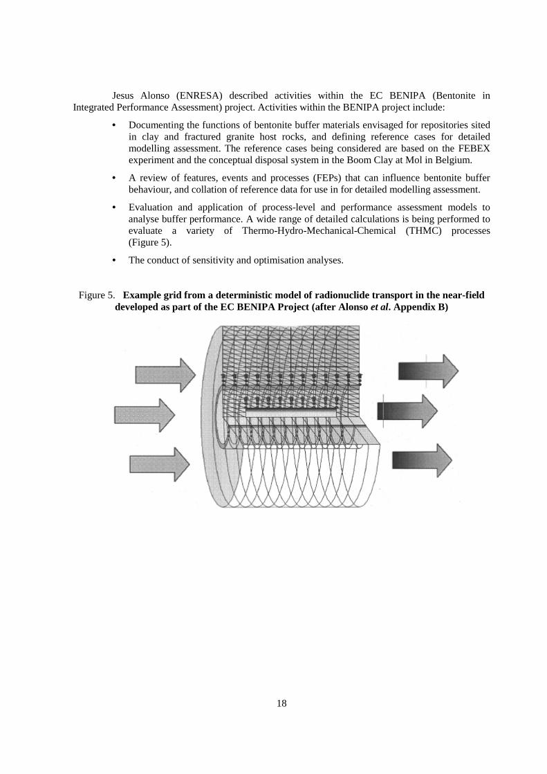
Jesus Alonso (ENRESA) described activities within the EC BENIPA (Bentonite inIntegrated Performance Assessment) project. Activities within the BENIPA project include:
• Documenting the functions of bentonite buffer materials envisaged for repositories sitedin clay and fractured granite host rocks, and defining reference cases for detailedmodelling assessment. The reference cases being considered are based on the FEBEXexperiment and the conceptual disposal system in the Boom Clay at Mol in Belgium.
• A review of features, events and processes (FEPs) that can influence bentonite bufferbehaviour, and collation of reference data for use in for detailed modelling assessment.
• Evaluation and application of process-level and performance assessment models toanalyse buffer performance. A wide range of detailed calculations is being performed toevaluate a variety of Thermo-Hydro-Mechanical-Chemical (THMC) processes(Figure 5).
• The conduct of sensitivity and optimisation analyses.
Figure 5. Example grid from a deterministic model of radionuclide transport in the near-fielddeveloped as part of the EC BENIPA Project (after Alonso et al. Appendix B)

19
4. WORKING GROUP SESSIONS
The following sections summarise the results of the discussions by the four working groups.The remit and membership of the working groups are detailed in Appendix C.
4.1 Working Group A: Design Criteria and Construction
The EBS comprises a variety of components, including the waste form itself, waste canisters,backfill, seals and plugs. The general purpose of an EBS is the containment and long-termminimisation/retardation of radionuclide releases. The specific role that an EBS is designed to play ina particular waste disposal concept is dependent on the design and on the site-specific conditions. Thisrole may be defined in the design criteria.
The group considered a number of topics related to design criteria and construction, anddeveloped proposals for two subsequent workshops to address some of the issues identified. Theworkshops would draw on a mix of specialists from engineering, EBS characterisation, and processmodelling and safety assessment. The potential objectives and contents of each proposed workshop aredescribed in the following sections.
4.1.1 Design Requirements and Constraints
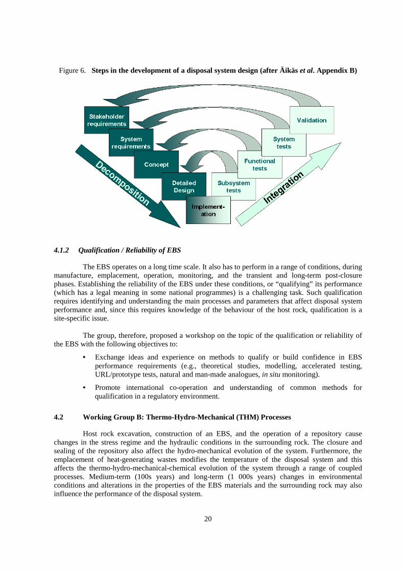
The group noted that the development of an EBS design proceeds from societal andstakeholder requirements, to system requirements, to a design concept, to a detailed design and, thus,to practical decisions on implementation (Figure 6). These requirements are influenced by constraintssuch as site characteristics, existing waste packages, mining technology, national waste inventory, andoperational safety.
It was, therefore, proposed to have a workshop on the topic of design requirements andconstraints with the following objectives:
• State the design requirements for various facilities and identify their basis, including theevolution of these requirements.
• Promote common understanding of the requirements, and of methods for linkingbetween societal and stakeholder requirements to detailed design concepts and decisions.
• Share ideas and experiences on working with challenging requirements and constraints.
• Better understand the basis for differences in national EBS designs.
20
Figure 6. Steps in the development of a disposal system design (after Äikäs et al. Appendix B)
4.1.2 Qualification / Reliability of EBS
The EBS operates on a long time scale. It also has to perform in a range of conditions, duringmanufacture, emplacement, operation, monitoring, and the transient and long-term post-closurephases. Establishing the reliability of the EBS under these conditions, or “qualifying” its performance(which has a legal meaning in some national programmes) is a challenging task. Such qualificationrequires identifying and understanding the main processes and parameters that affect disposal systemperformance and, since this requires knowledge of the behaviour of the host rock, qualification is asite-specific issue.
The group, therefore, proposed a workshop on the topic of the qualification or reliability ofthe EBS with the following objectives to:
• Exchange ideas and experience on methods to qualify or build confidence in EBSperformance requirements (e.g., theoretical studies, modelling, accelerated testing,URL/prototype tests, natural and man-made analogues, in situ monitoring).
• Promote international co-operation and understanding of common methods forqualification in a regulatory environment.
4.2 Working Group B: Thermo-Hydro-Mechanical (THM) Processes
Host rock excavation, construction of an EBS, and the operation of a repository causechanges in the stress regime and the hydraulic conditions in the surrounding rock. The closure andsealing of the repository also affect the hydro-mechanical evolution of the system. Furthermore, theemplacement of heat-generating wastes modifies the temperature of the disposal system and thisaffects the thermo-hydro-mechanical-chemical evolution of the system through a range of coupledprocesses. Medium-term (100s years) and long-term (1 000s years) changes in environmentalconditions and alterations in the properties of the EBS materials and the surrounding rock may alsoinfluence the performance of the disposal system.

21
One difficulty the working group had was limiting its attention to THM processes only, sinceit was recognised that proper investigation of THM effects could only be achieved by consideration ofchemical processes, and changes in chemical properties could, in turn, only be confidently resolved byconsideration of THM processes.
The performance and design of an EBS are not dependent solely on the undisturbed ambientconditions and the initial properties of the EBS materials and repository host rock, but depend on howthose conditions and properties change as a result of repository construction, operation and wasteemplacement. These repository-induced influences evolve in a complicated manner that depends onthe type of waste, host rock formation, and EBS design. The manner in which the properties andTHMC conditions in the EBS and host rock are affected is further dependent on factors such as therock excavation methods used, the duration of operations prior to closure, the heterogeneities anddiscontinuities in the host rock, the engineering measures taken to maintain excavation stability andreduce water inflows, the chemical and mechanical properties of the materials used for backfilling andsealing, and the thermal load to which the rock is subjected.
To help focus its discussion, Group B first reviewed the definition of the near-fieldenvironment. For the purposes of the group’s discussion, and consistent with the IGSC-EBS Projectdefinition, the near-field environment was considered to include the EBS and that portion of the rockmass in which there would occur significant change (temporary or permanent) in THMC properties.These changes would arise from mining, heat transfer, mechanical deformations and stresses, andmass-transfer exchange between underground facilities and the surrounding host rock, including fluidmobilisation, degassing, phase changes, weathering of minerals, precipitation of new phases, andintroduction of biological organisms.
To characterise the near-field environment it may be necessary to consider a range ofcoupled processes, including the couplings between thermal, hydrological, mechanical, and chemicalprocesses, as well as possible associated impacts from biological and radiological processes. Forexample, heat from the waste can cause thermal gradients, which induce mechanical stresses anddeformations, which can mobilise water, which can subsequently dissolve minerals. Gas generation,due to biodegradation of organic materials in the waste, can lead to two-phase flow conditions in thebuffer and induce additional water movement, mechanical stresses, and chemical processes.
The group concluded that all of the key processes described above need to be considered inorder to establish appropriate design requirements for the EBS, and to evaluate the performance of theEBS and the repository in a safety case. The group also considered that some of the key processesneed to be better understood. The group felt that modelling of coupled processes, experiments andfield (URL) measurements are essential for the development of a better understanding of the keyprocesses, and for devising sensible and technically-defensible design criteria based on scientificunderstanding rather than arbitrary assumptions.
The group developed proposals for workshops on five topics:
1. Thermal management and analysis.
2. Upscaling and extrapolation.
3. EBS scenarios (including consideration of fabrication and operational errors).
4. Retrievability and monitoring.
5. Gas in repository systems.
22
Of the range of topics considered, the group considered that developing a betterunderstanding of thermal loading and management is a priority for establishing appropriate designrequirements. The treatment of uncertainties, arising from upscaling in space and extrapolation overtime of processes and properties, was also considered to be an important issue that needs to beaddressed. The objectives of the proposed workshops on thermal management and analysis, and onupscaling and extrapolation are summarised below.
4.2.1 Thermal Management and Analysis
The objective of a workshop on thermal management and analysis would be to evaluateexisting data, models, and safety considerations and consider maximum temperature limits for theEBS and the near-field. Key issues and questions to address would include:
• What THMC processes need to be considered?
• How do you model relevant THMC processes and what analyses are needed?
• How can uncertainty and evolution of properties be considered?
• What data and experiments are needed to better characterise THMC processes?
• Is there a need to specify thermal design constraints or limits? If so, should they bespecified in terms of temperature, power density or some other measure, and at whatlevel might such constraints be established?
4.2.2 Upscaling and Extrapolation
The objective of a workshop on THMC upscaling and extrapolation would be to identifyremaining uncertainties and explore approaches to their resolution. Key issues and questions toaddress would include:
• How do you design “scaled” experiments to account for processes at large scales and/orlong time frames?
• How do you scale-up laboratory and field properties to account for natural variability?
• How do you account for long-term evolution of properties?
4.3 Working Group C: Geochemical Processes
Group C focused on identifying suitable topics within the area of geochemistry for furtherdevelopment under the IGSC-EBS Project.
The group began with a brainstorming session to identify important geochemical issues.These issues were then gathered into areas that could sensibly be considered during a workshop. Thepotential workshops thus identified were then evaluated in terms of their relevance to the range ofradioactive waste management programmes represented within the IGSC-EBS Project, and in terms oftheir potential to promote meaningful international co-operation.
The list of issues identified by the group is presented in Table 1. It is recognised that the listcontained in Table 1 is neither comprehensive, nor are the items independent.

23
The group considered the potential benefits of international workshops in the areas ofcorrosion, solution chemistry, the alteration of non-metallic engineered barriers, and nuclear criticality.The group concluded that it should recommend a single workshop that encompassed both solutionchemistry and the alteration of non-metallic engineered barriers. The rationale for such a workshop isdescribed in the following section.
Table 1. Geochemical issues considered by Working Group C
Issue Notes
Establishment ofthe geochemicalenvironment
The chemical environment of the near-field will evolve after repositoryclosure and influence radionuclide release and disposal system performance.
CorrosionCorrosion of metal containers/canisters may determine the containmentperiod, but may also have an effect on the geochemical environment.
Solution chemistry
The chemistry of the water in the near-field will have a significant effect onall geochemical processes. Important parameters include, pH, redoxconditions, ionic strength and the concentrations of inorganic and organicligands.
Thermal evolution Elevated temperatures and thermal gradients will influence the chemistry ofwaters in the near-field and the behaviour of EBS materials.
Alternation of EBSmaterials
The chemical degradation of buffer and backfill materials over repositorytime scales will influence disposal system performance.
Corrosion producteffects
Canister corrosion products may become abundant in the near-field for manyrepository concepts.
Buffer erosionLow ionic-strength (dilute) waters may have a physical effect on clay-basedEBS materials.
Colloid formation Degradation of EBS barriers may lead to colloid generation.
Microbes It is almost impossible to exclude microbial activity in the repository.
AdditivesThe secondary effects of components that are added to EBS materials toenhance repository performance are uncertain.
4.3.1 Solution Chemistry and the Alteration of Non-metallic Engineered Barriers
4.3.1.1 Solution Chemistry
In order to evaluate the potential for radionuclide transport away from a waste repository andto assess the long-term performance of the EBS and the disposal system, it is essential to understandthe composition and chemistry of waters in the repository. Information about relevant processes thataffect water compositions and chemistry can be gathered from field and laboratory experiments,thermodynamic databases, scientific models and expert judgement. This information may be used todevelop a model of solution chemistry. Ideally, such a model would feature all of the significantprocesses and their couplings, and would account for the temporal and spatial evolution of relevantcomponents.

24
The group considered that the treatment of solution chemistry would be a good topic for aNEA workshop for the following reasons:
• Solution chemistry will affect EBS performance as well as radionuclide transport anddisposal system performance.
• Safety assessment models of solution chemistry are often over-simplified.
• Solution chemistry is relevant to all national waste disposal concepts.
• It may be difficult to make conservative assumptions regarding the many coupledprocesses that affect, or are affected by, solution chemistry.
4.3.1.2 Alteration of Non-metallic Barriers
Most repository concepts include engineered barriers that are expected to functioneffectively over very long periods. Inevitably, the properties of these barriers will change (degrade)with time. One of the main drivers for degradation is chemical alteration as a result of interactionswith repository waters. There is, thus, a strong coupling between the solution chemistry topicsdiscussed above and barrier alteration.
The group felt that the alteration of long-term barriers other than waste containers(e.g., buffer, backfill) would be a good topic for a NEA workshop for the following reasons:
• Such barriers are typically required to function effectively over very long periods.
• Barrier alteration will affect radionuclide transport as well as barrier performance.
• Although canister/container/overpack corrosion is one of the most important processes ina repository because it usually determines the duration of the initial isolation period, thegroup decided that corrosion would not be a suitable topic for a workshop under theIGSC-EBS Project. This conclusion was reached because a wide variety of materials isused in the different national programmes, because the important corrosion processesvary amongst the different materials, and because other international projects areactively considering corrosion processes
4.4 Working Group D: Radionuclide Release and Migration
The aim of discussions within Group D was to arrive at recommendations on how the IGSC-EBS Project should make further consideration of issues related to radionuclide migration.
The discussions focused largely on radionuclide retention within the EBS and the near-field.The group recognised, however, that the materials of the EBS and the near-field also contribute to thesafety of disposal systems by isolating the waste form.
The group noted that the EBS and the near-field currently receive more attention than waspreviously the case, possibly because the materials of the EBS and conditions within the near-field arebetter known than in the far-field.
The group was of the opinion that the IGSC-EBS Project would be best served by combiningfuture consideration of geochemistry with radionuclide transport, and instead drawing a distinctionbetween geochemical and radionuclide transport processes within the “internal” components of the
25
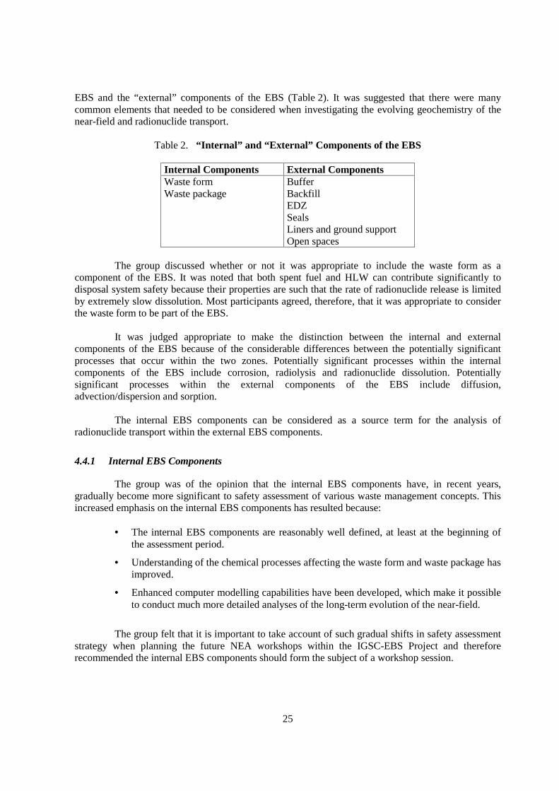
EBS and the “external” components of the EBS (Table 2). It was suggested that there were manycommon elements that needed to be considered when investigating the evolving geochemistry of thenear-field and radionuclide transport.
Table 2. “Internal” and “External” Components of the EBS
Internal Components External ComponentsWaste formWaste package
BufferBackfillEDZSealsLiners and ground supportOpen spaces
The group discussed whether or not it was appropriate to include the waste form as acomponent of the EBS. It was noted that both spent fuel and HLW can contribute significantly todisposal system safety because their properties are such that the rate of radionuclide release is limitedby extremely slow dissolution. Most participants agreed, therefore, that it was appropriate to considerthe waste form to be part of the EBS.
It was judged appropriate to make the distinction between the internal and externalcomponents of the EBS because of the considerable differences between the potentially significantprocesses that occur within the two zones. Potentially significant processes within the internalcomponents of the EBS include corrosion, radiolysis and radionuclide dissolution. Potentiallysignificant processes within the external components of the EBS include diffusion,advection/dispersion and sorption.
The internal EBS components can be considered as a source term for the analysis ofradionuclide transport within the external EBS components.
4.4.1 Internal EBS Components
The group was of the opinion that the internal EBS components have, in recent years,gradually become more significant to safety assessment of various waste management concepts. Thisincreased emphasis on the internal EBS components has resulted because:
• The internal EBS components are reasonably well defined, at least at the beginning ofthe assessment period.
• Understanding of the chemical processes affecting the waste form and waste package hasimproved.
• Enhanced computer modelling capabilities have been developed, which make it possibleto conduct much more detailed analyses of the long-term evolution of the near-field.
The group felt that it is important to take account of such gradual shifts in safety assessmentstrategy when planning the future NEA workshops within the IGSC-EBS Project and thereforerecommended the internal EBS components should form the subject of a workshop session.
26
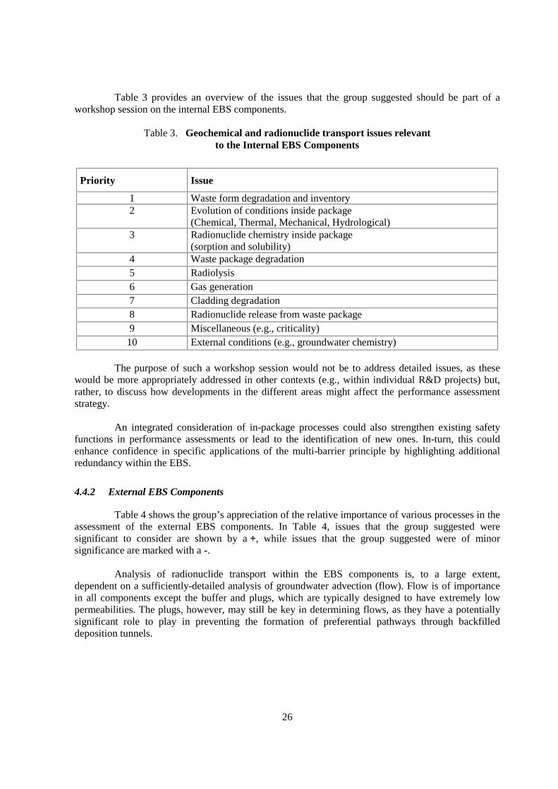
Table 3 provides an overview of the issues that the group suggested should be part of aworkshop session on the internal EBS components.
Table 3. Geochemical and radionuclide transport issues relevantto the Internal EBS Components
Priority Issue
1 Waste form degradation and inventory2 Evolution of conditions inside package
(Chemical, Thermal, Mechanical, Hydrological)3 Radionuclide chemistry inside package
(sorption and solubility)4 Waste package degradation5 Radiolysis6 Gas generation7 Cladding degradation8 Radionuclide release from waste package9 Miscellaneous (e.g., criticality)10 External conditions (e.g., groundwater chemistry)
The purpose of such a workshop session would not be to address detailed issues, as thesewould be more appropriately addressed in other contexts (e.g., within individual R&D projects) but,rather, to discuss how developments in the different areas might affect the performance assessmentstrategy.
An integrated consideration of in-package processes could also strengthen existing safetyfunctions in performance assessments or lead to the identification of new ones. In-turn, this couldenhance confidence in specific applications of the multi-barrier principle by highlighting additionalredundancy within the EBS.
4.4.2 External EBS Components
Table 4 shows the group’s appreciation of the relative importance of various processes in theassessment of the external EBS components. In Table 4, issues that the group suggested weresignificant to consider are shown by a +, while issues that the group suggested were of minorsignificance are marked with a -.
Analysis of radionuclide transport within the EBS components is, to a large extent,dependent on a sufficiently-detailed analysis of groundwater advection (flow). Flow is of importancein all components except the buffer and plugs, which are typically designed to have extremely lowpermeabilities. The plugs, however, may still be key in determining flows, as they have a potentiallysignificant role to play in preventing the formation of preferential pathways through backfilleddeposition tunnels.

27
Table 4. Processes influencing mass transport in the External EBS Components
Processes Influencing Mass Transport
Advection Retardation Diffusion Colloids
Buffer - + + -
Backfill + - + +
EDZ + - + +
Seals - +/- + -
Liners andground support + - + +
Ext
erna
l EB
S C
ompo
nent
s
Open spaces + - + +
Key: + = significant to consider; - = of minor importance.
Radionuclide retardation in the buffer is important to safety in many repository concepts.The relative importance depends on, for example, the thickness of the buffer and the expected lifetimeof the canister. The group was of the opinion that radionuclide retardation in the other parts of the EBSsystem is, in principle, more difficult to rely upon and probably less significant.
The group considered that is important to consider the effects of diffusion in all the parts ofthe near-field subsystem and especially in components such as the buffer where it is the onlysignificant transport mechanism.
In most spent fuel and HLW disposal concepts, the buffer is designed to play a significantrole in preventing the release of radionuclides in colloidal form by filtration. In contrast, the transportof gas through the buffer has to be considered. With the possible exception of seals, it is necessary toconsider both colloid and gas transport through other parts of the disposal system.
The group discussed the potential for radionuclide release and transport calculations to assistin optimising repository design. The group concluded that results from radionuclide release andtransport calculations could be used as an input to studies aimed at optimising the design and layout ofthe repository and the EBS. The group noted that in order to do this, the radionuclide release andtransport calculations are likely to need to be supported by a detailed model of flows around therepository, so that significant flowpaths could be identified. The group noted that the importance ofresults from radionuclide release and transport calculations to optimisation studies would also dependon the relative significance of the far-field in the performance of the disposal system underconsideration.
The group concluded that the IGSC-EBS Project should ideally focus on the exchange ofinformation and ideas related to various principles of implementing an EBS. The group suggested thatstrategic considerations are easily forgotten and that detailed technical issues probably receive more

28
attention than is really justified. The group considered that detailed considerations about technicalissues might best be resolved in other fora.
The group concluded that the topic of radionuclide release and transport would form asensible basis for an international workshop and that it might be beneficial for the workshop to bedivided so that one part would consider the internal EBS components and that a second wouldconsider the external EBS components.
Finally the group developed a preliminary list of common issues for consideration at allfuture workshops within the IGSC-EBS Project (Table 5).
Table 5. Common issues to be considered at future workshops
Common Issues
Confidence Building
Model Simplification
Performance Assessment Modelling Strategy
Conservatism / Realism
Extrapolation over Long Time Periods
Safety Allocation
New Safety FEPs
Treatment of Evolving Conditions
Alternative ScenariosPerformance Assessment Feedback into DesignOptimisationUncertainty/Variability/Heterogeneity

29
5. WORKSHOP CONCLUSIONS
5.1 Technical Issues
The following conclusions can be drawn from the responses to the NEA questionnaire on theEBS and the discussions at the workshop.
There is good agreement on the definition of the EBS and on its primary role: thecontainment and long-term minimisation/retardation of radionuclide releases. All of the radioactivemanagement programmes include an EBS giving multiple barriers to radionuclide migration, andproviding reserves of performance greater than required for compliance with safety criteria (e.g., doseor risk limits). Although the EBS plays a significant role in providing the required level of disposalsystem performance, there are few specific regulatory requirements of the EBS that go beyond therequirement for a robust system of multiple barriers.
There is generally good consistency amongst national EBS designs for spent fuel and HLWdisposal, but less for ILW:
• For spent fuel, the main components are UO2, mixed uranium and plutonium oxides(MOX), and other waste matrices, steel or copper-iron containers, copper, steel or Ni-alloy overpacks, and bentonite or bentonite-based buffers.
• For HLW, the main components of the EBS are a borosilicate glass matrix, steelcontainers / overpacks, and bentonite or bentonite-based buffers.
• For ILW, the main components of the EBS include a wide variety of waste matrices,(e.g. concrete-conditioned wastes), steel or concrete containers, and a wide variety ofbackfill materials, (e.g. concrete, bentonite-based materials, salt-concrete).
The greater variation in the ILW disposal concepts reflects the greater number of ILW wastestreams and the wide range of different disposal sites considered in the survey.
The main functions of EBS components can be summarised as follows:
• The waste matrix is designed to provide a stable waste form that is resistant to leachingand gives slow rates of radionuclide release for the long-term (10 000 – 150 000 years).
• The container/overpack is designed to facilitate waste handling, emplacement andretrievability, and to provide containment for ~ 500 – 1 000 years or longer.
• The buffer/backfill is designed to stabilise the repository excavations and the thermo-hydro-mechanical conditions, and to provide low permeabilities and diffusivities, andlong-term retardation.
• The other EBS components are designed to prevent releases via tunnels and shafts and toprevent access to the repository.
30
Many FEPs can influence the EBS, depending on the particular waste types and sitecharacteristics. Potentially important FEPs include:
• Thermo-hydro-mechanical and chemical (THMC) evolution
• climate change.
• Glass dissolution/waste leaching rates.
• Container corrosion rates, container defects.
• Buffer re-saturation, swelling, and long-term alteration.
• Radionuclide transport in the buffer.
• Gas generation in container and transport through the buffer / backfill.
The need for monitoring of the repository during the active control phase is recognised inmost programmes, but monitoring plans are generally in an early phase of development. Someprogrammes are considering monitoring phases in excess of fifty years.
Many programmes are actively involved in experiments in Underground ResearchLaboratories (URLs). This is an area of extensive international collaboration and there are clear linksbetween URL experiments, laboratory experiments, process modelling and data gathering. Someprogrammes include URL experiments in an iterative process of performance assessment and designrefinement. It is not clear, however, that URL experiments build stakeholder confidence (e.g., throughdemonstration).
Peer review is an important positive process that enhances confidence and should be anactive part of the on-going design and assessment process. Issues identified through peer reviews indifferent countries include the need for:
• Demonstration of technical feasibility.
• Further R&D on particular topics.
• Balance between EBS and natural barriers.
• Consideration of uncertainties in expected performance.
Remaining design uncertainties relate mainly to issues of how to link EBS design andemplacement methods to disposal system performance. Key characterisation uncertainties include theTHMC properties of buffer and backfill materials and the evolution of those properties, the effect ofgas generation, the determination of parameter values for safety analysis, and the release and uptakemechanisms of 14C.
Research models are intended to justify, or demonstrate, the scientific and technical basis forsimplified performance assessment models. Performance assessment models are used to develop anassessment of overall system performance for comparison with safety standards and otherrequirements. Uncertainties in disposal system performance can be accounted for using conservativeassumptions, probabilistic techniques, deterministic sensitivity studies, and “what if?” calculations.
Performance assessment uncertainties often relate to the determination of parameter valuesthat are representative of the large spatial scales and long time scales of interest to radioactive waste
31
disposal (e.g., long-term metal corrosion and glass dissolution rates, large-scale radionuclidedispersion coefficients). Other relevant performance assessment uncertainties include parameter valuesfor thermodynamic data, geochemistry and radionuclide retardation, long-term buffer stability andspatial heterogeneity.
Lessons learnt from performance assessments include:
• Adopt a methodical, systematic and fully documented approach to repository design andoptimisation.
• Simple designs and models are easier to implement and verify.
• Integrate EBS design and performance assessment activities within iterative optimisationcycles.
• Ensure, and demonstrate, design feasibility.
• Continue to build confidence in performance assessment.
• Focus on the most important issues (e.g., through the use of risk-informed approaches).
Performance assessments also suggest that EBS systems are very effective in containingradioactive wastes.
5.2 Programmatic Issues
On the third day of the workshop, it was agreed that there was strong support amongst themany countries represented for a continued international project on the EBS and that it was importantto present as an overall outcome an account of how EBS design is developed, justified andimplemented using state-of-the-art knowledge.
The Committee considered the format of the future programme and decided that the IGSC-EBS Project would be best served by a sequence of further workshops. It was also decided that, giventhe status of the different national radioactive waste management programmes, a timeframe of no morethan a further four years should be envisaged for the overall duration of the project.
Given the workshop format and recommended duration of the project, the Committeeconcluded that a sequence of four workshops would be practicable, as follows:
Workshop 1 Design Requirements and Constraints (see Section 4.1.1).Workshop 2 Process Issues:
− Thermal management and analysis (see Section 4.2.1).− Alteration of non-metallic barriers and evolution of solution chemistry
(see Section 4.3.1).− Radionuclide release and transport (see Section 4.4).
Workshop 3 Role of Performance Assessment and Process Models.Workshop 4 Design Confirmation and Demonstration (see Section 4.1.2).
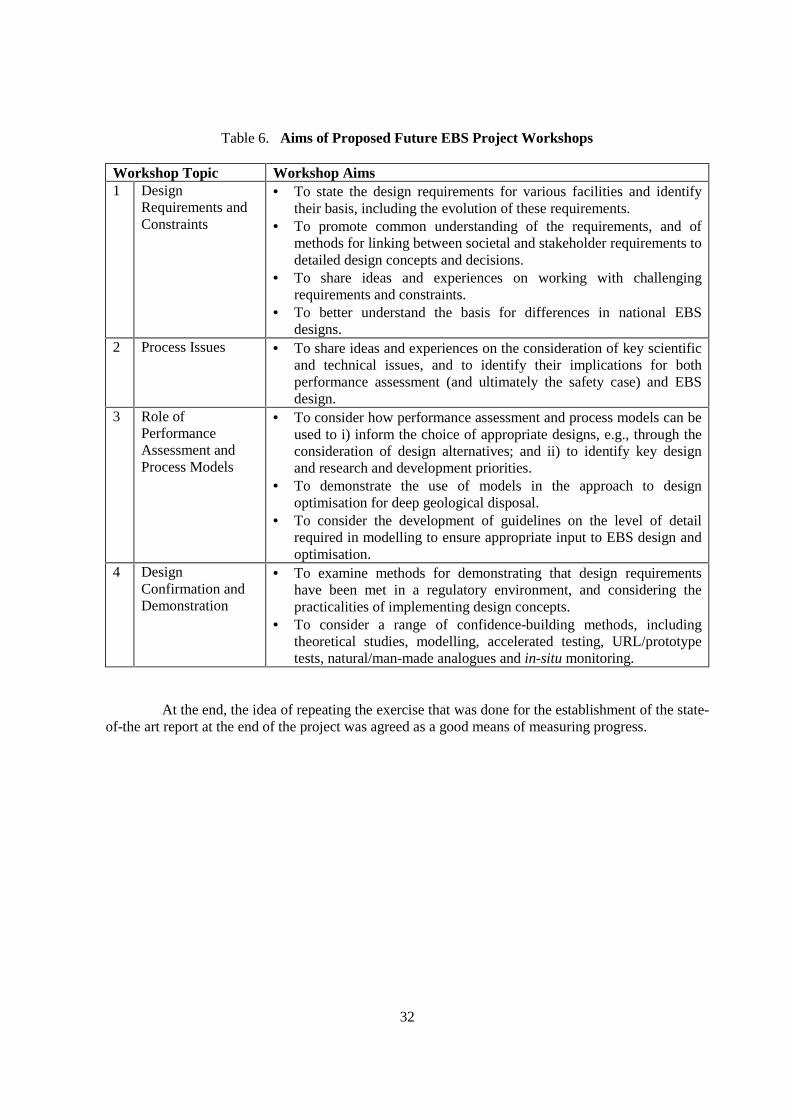
This sequence of workshops will lead the IGSC-EBS Project through an optimisation cycleof the type discussed at the workshop (e.g., Figure 1). The aims of the proposed workshops aresummarised in Table 6.
32
Table 6. Aims of Proposed Future EBS Project Workshops
Workshop Topic Workshop Aims1 Design
Requirements andConstraints
• To state the design requirements for various facilities and identifytheir basis, including the evolution of these requirements.
• To promote common understanding of the requirements, and ofmethods for linking between societal and stakeholder requirements todetailed design concepts and decisions.
• To share ideas and experiences on working with challengingrequirements and constraints.
• To better understand the basis for differences in national EBSdesigns.
2 Process Issues • To share ideas and experiences on the consideration of key scientificand technical issues, and to identify their implications for bothperformance assessment (and ultimately the safety case) and EBSdesign.
3 Role ofPerformanceAssessment andProcess Models
• To consider how performance assessment and process models can beused to i) inform the choice of appropriate designs, e.g., through theconsideration of design alternatives; and ii) to identify key designand research and development priorities.
• To demonstrate the use of models in the approach to designoptimisation for deep geological disposal.
• To consider the development of guidelines on the level of detailrequired in modelling to ensure appropriate input to EBS design andoptimisation.
4 DesignConfirmation andDemonstration
• To examine methods for demonstrating that design requirementshave been met in a regulatory environment, and considering thepracticalities of implementing design concepts.
• To consider a range of confidence-building methods, includingtheoretical studies, modelling, accelerated testing, URL/prototypetests, natural/man-made analogues and in-situ monitoring.
At the end, the idea of repeating the exercise that was done for the establishment of the state-of-the art report at the end of the project was agreed as a good means of measuring progress.
33
6. REFERENCES
Bennett, D.G., Papenguth, H.W., Chu, M.S.Y., Galson, D.A., Duerden, S.L. and Matthews, M. (1998)International Workshop on the Uses of Backfill in Nuclear Waste Repositories, Carlsbad, NewMexico, USA, May 1998. US Department of Energy / Environment Agency R&D Technical ReportP178. Bristol: Environment Agency.
NEA-EC (2003) Engineered Barrier Systems and the Safety of Deep Geological Repositories, State-of-the-art Report, EUR 19964 EN.; Paris 2003 , ISBN 92-64-18498-8
JNC (2000) H12: Project to Establish the Scientific and Technical Basis for HLW Disposal in Japan,Supporting Report 2, JNC TN1410 2000-003.
POSIVA (2000) Disposal of Spent Fuel in Olkiluoto Bedrock, Programme for Research Developmentand Technical Design for the Pre-Construction Phase. Posiva Oy Report No. 2000-14, Helsinki,Finland.

35
APPENDIX A
WORKSHOP AGENDA

37
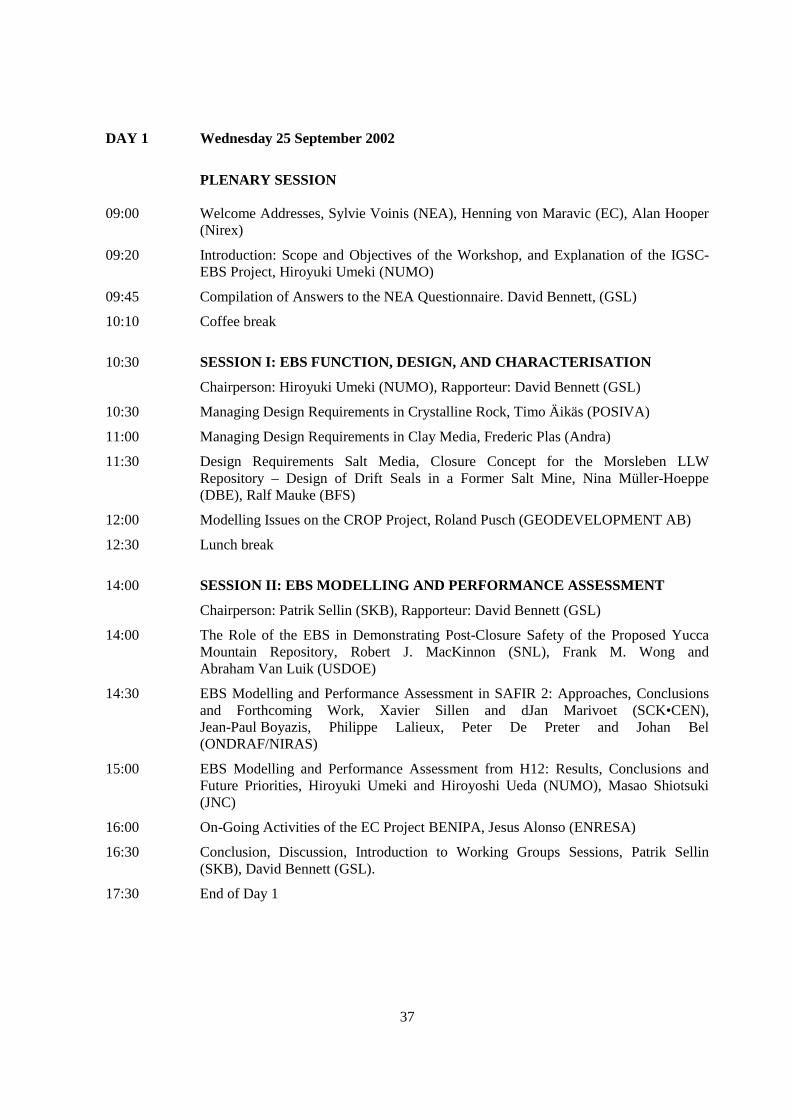
DAY 1 Wednesday 25 September 2002
PLENARY SESSION
09:00 Welcome Addresses, Sylvie Voinis (NEA), Henning von Maravic (EC), Alan Hooper(Nirex)
09:20 Introduction: Scope and Objectives of the Workshop, and Explanation of the IGSC-EBS Project, Hiroyuki Umeki (NUMO)
09:45 Compilation of Answers to the NEA Questionnaire. David Bennett, (GSL)
10:10 Coffee break
10:30 SESSION I: EBS FUNCTION, DESIGN, AND CHARACTERISATION
Chairperson: Hiroyuki Umeki (NUMO), Rapporteur: David Bennett (GSL)
10:30 Managing Design Requirements in Crystalline Rock, Timo Äikäs (POSIVA)
11:00 Managing Design Requirements in Clay Media, Frederic Plas (Andra)
11:30 Design Requirements Salt Media, Closure Concept for the Morsleben LLWRepository – Design of Drift Seals in a Former Salt Mine, Nina Müller-Hoeppe(DBE), Ralf Mauke (BFS)
12:00 Modelling Issues on the CROP Project, Roland Pusch (GEODEVELOPMENT AB)
12:30 Lunch break
14:00 SESSION II: EBS MODELLING AND PERFORMANCE ASSESSMENT
Chairperson: Patrik Sellin (SKB), Rapporteur: David Bennett (GSL)
14:00 The Role of the EBS in Demonstrating Post-Closure Safety of the Proposed YuccaMountain Repository, Robert J. MacKinnon (SNL), Frank M. Wong andAbraham Van Luik (USDOE)
14:30 EBS Modelling and Performance Assessment in SAFIR 2: Approaches, Conclusionsand Forthcoming Work, Xavier Sillen and dJan Marivoet (SCK•CEN),Jean-Paul Boyazis, Philippe Lalieux, Peter De Preter and Johan Bel(ONDRAF/NIRAS)
15:00 EBS Modelling and Performance Assessment from H12: Results, Conclusions andFuture Priorities, Hiroyuki Umeki and Hiroyoshi Ueda (NUMO), Masao Shiotsuki(JNC)
16:00 On-Going Activities of the EC Project BENIPA, Jesus Alonso (ENRESA)
16:30 Conclusion, Discussion, Introduction to Working Groups Sessions, Patrik Sellin(SKB), David Bennett (GSL).
17:30 End of Day 1

38
DAY 2 Thursday 26 September 2002
WORKING GROUP SESSIONS
09:00 - 10:30 Parallel Working Groups Sessions
10:30 - 11:00 Coffee break
11:00 - 12:30 Parallel Working Groups Sessions (cont’d)
12:30 - 14:00 Lunch break
14:00 - 15:30 Parallel Working Groups Sessions (cont’d)
15:30 - 16:00 Coffee break
16:00 - 17:30 Parallel Working Groups Sessions (cont’d)
17:30 End of Day 2
DAY 3 Friday 27 SEPTEMBER 2002
CONTINUATION OF WORKING GROUP SESSIONS
08:30 - 10:30 Parallel Working Groups Sessions (cont’d)
10:30 Coffee break
11:00 ROUND-UP PLENARY SESSION
Chairperson: Alan Hooper (Nirex), Rapporteur: David Bennett (GSL)
11:00 - 12:30 Reports from Working Groups A, B, C and D
12:30 - 14:00 Lunch break
14:00 Synthesis of the Workshop and Recommendations for Further Actions
14:30 Final Discussion and Closing of the Round-up Plenary Session
15:00 End of the Workshop
39
APPENDIX B
PAPERS PRESENTED TO THE WORKSHOP


41
MANAGING DESIGN REQUIREMENTS FOR A REPOSITORY IN CRYSTALLINE ROCK
Timo ÄikäsPosiva Oy, Finland
Posiva is preparing the geological disposal of spent nuclear fuel generated in Finland. TheOlkiluoto site in Eurajoki in Western Finland was selected for disposal in 2001 based on site selectionresearch programme carried out since 1983. The disposal concept as a reference in planning thegeological disposal and in decision making has been the KBS-3 type design. This concept comprises asystem of natural and engineered barriers. The characteristics of the system are long-lived copper-ironcanister and the bentonite buffer which surrounds the canister. These packages are placed in depositionrooms at sufficient depth in crystalline bedrock. Deposition rooms and access routes are backfilledwith suitable material to make possible the favourable conditions in the geosphere to return as much aspossible to the those before the construction the repository.
What are the system requirements of a disposal system? What shall the system fulfil, howwell, how much and when? The answer is that the system shall isolate the waste from organicenvironment and retard the transport of radionuclides towards the biosphere This shall be possibleeven in the distant future so that radioactive waste does not appear in unacceptable quantities in theenvironment. The requirements on isolation and retardation are based in Finland (and also elsewhere)on laws and/or other statutes and internationally recognised recommendations. Very common are alsorequirements on tendency towards redundancy when designing the solution for disposal system. These“top” requirements on the system are basically similar in spite of the geological environment.
KBS-3 or any other disposal system can be divided in sub-systems and components. Thefunctions these shall fulfil are very much the same in all systems designed so far. It can be simplifiedthat canister and buffer as sub-systems, for example, have to fulfil very similar requirementspractically in all host rocks where groundwater is present. Due to the different geologicalenvironments and processes prevailing (or anticipated) the design solutions only become different.
Requirements basically integrate the work of safety and performance assessments,characterisation of geological environment and engineering. Safety requirements and assessments telland evaluate what the system shall fulfil but they do not say in detail how and with which level ofconfidence the requirements shall be fulfilled. Performance assessment in principle should giveanswers to “how well”, what is adequate. The properties and processes in the geological environmentare the basis for developing functional requirements for sub-systems and components, as well as,effective design base. Engineering will design the solutions for engineered barriers and verifies theseagainst the requirements. The verification of the design solution cannot, however, be always bestraightforward testing but have to be sometimes based on indirect scientific evidence like seekingconfidence in corrosion resistance of copper canister. This process is iterative and can also be usedeffectively for optimisation of the disposal system.
42
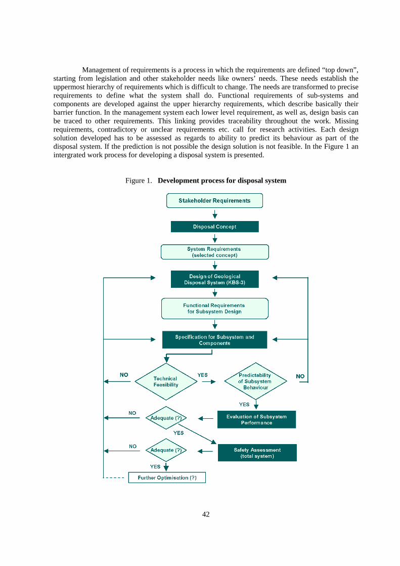
Management of requirements is a process in which the requirements are defined “top down”,starting from legislation and other stakeholder needs like owners’ needs. These needs establish theuppermost hierarchy of requirements which is difficult to change. The needs are transformed to preciserequirements to define what the system shall do. Functional requirements of sub-systems andcomponents are developed against the upper hierarchy requirements, which describe basically theirbarrier function. In the management system each lower level requirement, as well as, design basis canbe traced to other requirements. This linking provides traceability throughout the work. Missingrequirements, contradictory or unclear requirements etc. call for research activities. Each designsolution developed has to be assessed as regards to ability to predict its behaviour as part of thedisposal system. If the prediction is not possible the design solution is not feasible. In the Figure 1 anintergrated work process for developing a disposal system is presented.
Figure 1. Development process for disposal system
43
MANAGING DESIGN REQUIREMENTS OF THE FRENCH HLLW PROGRAMMEIN CLAY MEDIA
Jean-Michel Hoorelbeke, Stefan Mayer and Frédéric PlasAndra, France
1. Introduction
Design requirements of the man made components of the repository, including theEngineered Barrier System (EBS) are established based on a list of considerations. Where applicable,these design requirements address general and EBS specific regulatory considerations, in an effort toprovide technologically feasible and economically viable solutions. They take into account theinteractions between the construction and operation of the EBS and the natural environment. Theyrespond to the specific attributes of waste types. They evolve taking into consideration lessons learntfrom prior safety assessments, peer review comments and regulatory authority requirements andrecommendations.
Managing design requirements is assisted by the compilation of a set of comprehensiveSpecifications of Functional and Technical Requirements (SFTR). These are issued taking intoaccount all possible sources of requirements and constraints imposed on the design, construction,operation, and long term safety of a repository. They include both specific input data as well asrequirements that are translated into prescriptions for the design. The SFTR are established based oncurrent knowledge and uncertainties.
Managing design requirements is an iterative process, which must also take into account thepotential evolution of knowledge, design options, regulatory or other “high-level” requirements, andconstruction and operation procedures. For example, reducing uncertainty about the dissolution modeland rate of vitrified waste may allow to relax design requirements on waste package (WP) lifetime. Asensitivity analysis identifying those parameters most important to performance may focus attentionon associated design requirements. Requiring the implementation of an observation program duringrepository operation adds complexity, which may translate into additional modeling needs and designrequirements. Using construction and operation procedures that minimize any negative impact onnatural barrier performance may allow to relax those design requirements intended to compensate forsuch an impact. Any such evolution having an implication on design requirements is tracked in theSFTR.
Among other things, the SFTR thus represent an important link between design requirementsand scientific understanding, operational and long term safety considerations, and performanceassessment. An initial understanding of processes and parameters important to design is gained fromthe phenomenological analysis of specific aspects of the repository and their evolution with time. Theresulting estimates of temperature, pressure, etc., evolutions contribute to the first set of designrequirements. As design choices are developed and known to some detail, related process models may
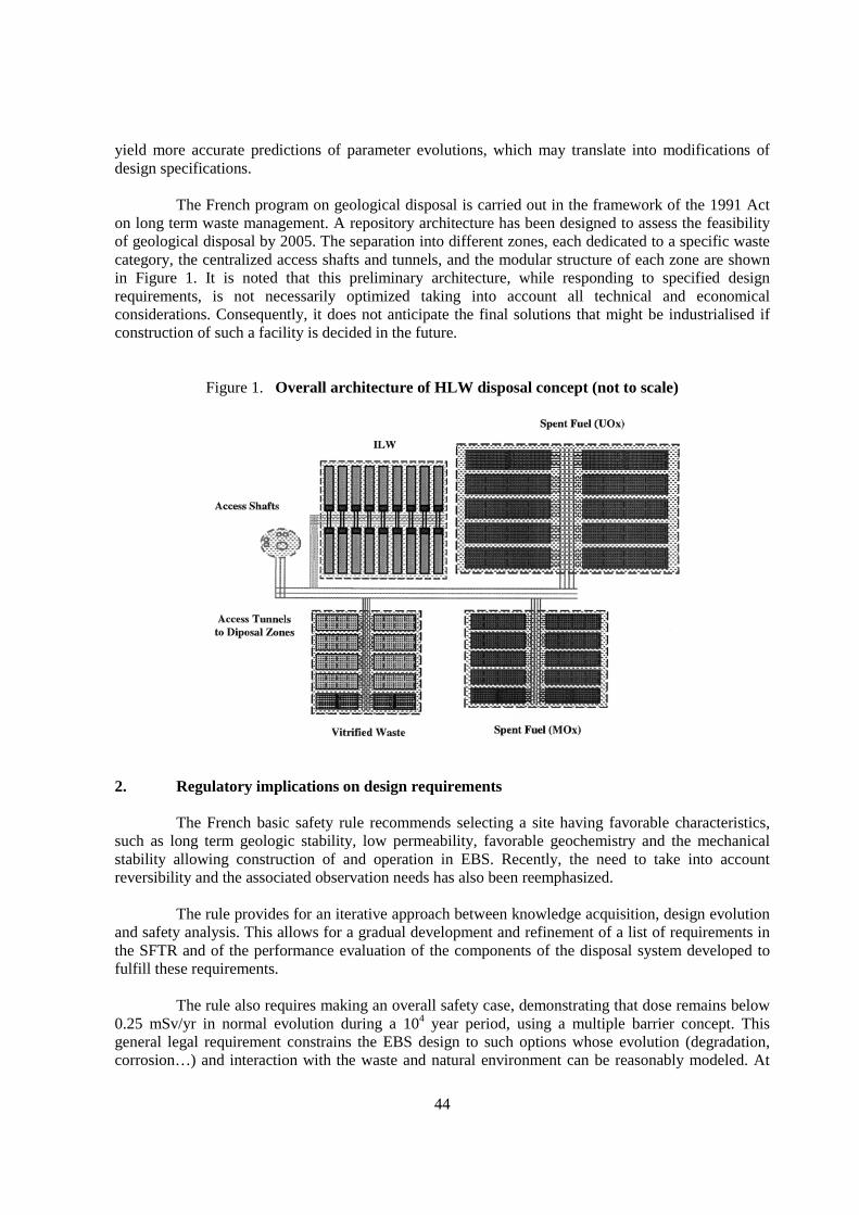
44
yield more accurate predictions of parameter evolutions, which may translate into modifications ofdesign specifications.
The French program on geological disposal is carried out in the framework of the 1991 Acton long term waste management. A repository architecture has been designed to assess the feasibilityof geological disposal by 2005. The separation into different zones, each dedicated to a specific wastecategory, the centralized access shafts and tunnels, and the modular structure of each zone are shownin Figure 1. It is noted that this preliminary architecture, while responding to specified designrequirements, is not necessarily optimized taking into account all technical and economicalconsiderations. Consequently, it does not anticipate the final solutions that might be industrialised ifconstruction of such a facility is decided in the future.
Figure 1. Overall architecture of HLW disposal concept (not to scale)
2. Regulatory implications on design requirements
The French basic safety rule recommends selecting a site having favorable characteristics,such as long term geologic stability, low permeability, favorable geochemistry and the mechanicalstability allowing construction of and operation in EBS. Recently, the need to take into accountreversibility and the associated observation needs has also been reemphasized.
The rule provides for an iterative approach between knowledge acquisition, design evolutionand safety analysis. This allows for a gradual development and refinement of a list of requirements inthe SFTR and of the performance evaluation of the components of the disposal system developed tofulfill these requirements.
The rule also requires making an overall safety case, demonstrating that dose remains below0.25 mSv/yr in normal evolution during a 104 year period, using a multiple barrier concept. Thisgeneral legal requirement constrains the EBS design to such options whose evolution (degradation,corrosion…) and interaction with the waste and natural environment can be reasonably modeled. At
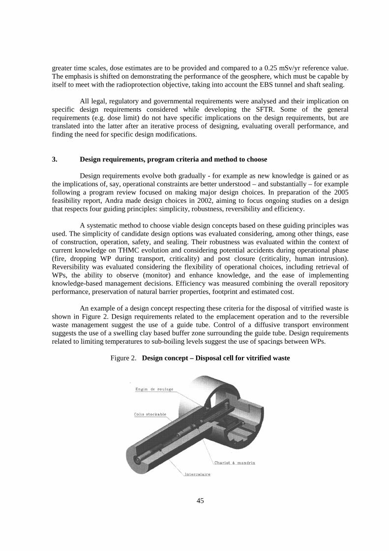
45
greater time scales, dose estimates are to be provided and compared to a 0.25 mSv/yr reference value.The emphasis is shifted on demonstrating the performance of the geosphere, which must be capable byitself to meet with the radioprotection objective, taking into account the EBS tunnel and shaft sealing.
All legal, regulatory and governmental requirements were analysed and their implication onspecific design requirements considered while developing the SFTR. Some of the generalrequirements (e.g. dose limit) do not have specific implications on the design requirements, but aretranslated into the latter after an iterative process of designing, evaluating overall performance, andfinding the need for specific design modifications.
3. Design requirements, program criteria and method to choose
Design requirements evolve both gradually - for example as new knowledge is gained or asthe implications of, say, operational constraints are better understood – and substantially – for examplefollowing a program review focused on making major design choices. In preparation of the 2005feasibility report, Andra made design choices in 2002, aiming to focus ongoing studies on a designthat respects four guiding principles: simplicity, robustness, reversibility and efficiency.
A systematic method to choose viable design concepts based on these guiding principles wasused. The simplicity of candidate design options was evaluated considering, among other things, easeof construction, operation, safety, and sealing. Their robustness was evaluated within the context ofcurrent knowledge on THMC evolution and considering potential accidents during operational phase(fire, dropping WP during transport, criticality) and post closure (criticality, human intrusion).Reversibility was evaluated considering the flexibility of operational choices, including retrieval ofWPs, the ability to observe (monitor) and enhance knowledge, and the ease of implementingknowledge-based management decisions. Efficiency was measured combining the overall repositoryperformance, preservation of natural barrier properties, footprint and estimated cost.
An example of a design concept respecting these criteria for the disposal of vitrified waste isshown in Figure 2. Design requirements related to the emplacement operation and to the reversiblewaste management suggest the use of a guide tube. Control of a diffusive transport environmentsuggests the use of a swelling clay based buffer zone surrounding the guide tube. Design requirementsrelated to limiting temperatures to sub-boiling levels suggest the use of spacings between WPs.
Figure 2. Design concept – Disposal cell for vitrified waste

46
4. Design requirements and site specific considerations
The design of the EBS is driven by the needs mainly to minimize impact on the favorablebarrier properties of the clay host rock and waste packaging, to restore and/or alleviate the detrimentalimpact of the EDZ, and to control the evolution of environmental conditions in the near field.
The “Meuse/Haute Marne” clay site currently studied for a potential HLLW repository (seeFigure 3) offers favorable conditions for radionuclide (RN) containment. The site has beengeologically stable for a period on the order of 108 yrs, with no significant seismic activity and anabsence of major faults. The undisturbed, reducing clay environment has low permeability without anyknown or anticipated preferential transport paths, suggesting a diffusion dominated transport modewith high sorption. These favorable properties translate into a transport time scale on the order of 105
yrs across a vertical layer thickness of 50 m at 500 m depth.
Figure 3. Localisation and Geological data of the “Meuse / Haute Marne “site
a) Geological map of the Parisian Basin b) Geological 3D diagram ofwith the “Meuse/Haute Marne” clay site the “Meuse/Haute Marne” clay site(URL location in red) (URL location in red)
c) Geological cross sections of the “Meuse/Haute Marne” site

47
Design requirements are developed to maintain diffusive transport properties around WPsand to prevent the development of a convective transfer zone through disposal and access tunnelsand/or the EDZ. As formalised in the SFTR, design is to allow for a construction method thatminimises the EDZ. Before backfilling and sealing: a) the role of the tunnel support is to preventconvergence of the clay host rock exceeding its plastic deformation limits, in order to prevent furthergrowth of the EDZ, and b) seal areas are to withstand the lithostatic pressure, in order to prevent long-term convergence of the host rock and the potential creation of an advective transport mode. Toalleviate the influence of the EDZ on the near-field transport properties, a swelling clay based buffercan be designed around respectively the C-waste and the spent fuel disposal packages.
5. Implications of waste (incl. Spent fuel) properties on the design requirements
A significant variety of HLLW types (incl. spent fuel) must be taken into account in thefeasibility study. To assist repository design, these were inventoried and categorised. Three maincategories are distinguished: B-type waste (ILW, mostly technological, compacted, and effluent byproduct waste, for example hulls and end-pieces; 8 major types are identified), C-type waste (variousvitrified waste types ; 5 major types are identified), and spent fuel (uranium oxide and mixed uraniumand plutonium oxide).
To allow for some flexibility in handling future evolutions of the inventory intended for therepository, the architecture is partitioned into four distinct zones separated by a specified minimumdistance (see Figure 1). Each zone is dedicated to a waste category. Within each zone, waste isdisposed into separate modules, to reduce the potential consequences of an intrusive event. Specificdesign requirements are developed for each of these zones, and possibly for some of the modules,taking into account the interaction between the waste considered, the EBS design and materials used,near-field, and the need to demonstrate a safety case based on the evolution within each zone.
Design requirements are influenced by WP dimensions, waste form, inventory, surfaceradiation levels, heat generation, gas generation, and chemistry. The SFTR contains dedicated sectionsfor each of the main waste types, to account for this range of waste type properties and to translatespecific needs into waste-specific design requirements. For example, spent fuel generates the mostsignificant thermal phase, and design requirements take into account the implications on near-fieldproperties. Figure 4 illustrates the design concept currently considered. Allowable WP density iscomputed to respect the design requirement of sub-boiling temperatures in the disposal zone. Theemplacement of several waste packages in a single disposal cell, separated by an adequate spacing, isalso considered.
Figure 4. Design concept – Disposal cell for spent fuel
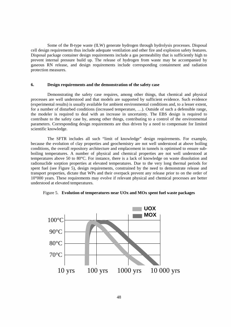
48
Some of the B-type waste (ILW) generate hydrogen through hydrolysis processes. Disposalcell design requirements thus include adequate ventilation and other fire and explosion safety features.Disposal package container design requirements include a gas permeability that is sufficiently high toprevent internal pressure build up. The release of hydrogen from waste may be accompanied bygaseous RN release, and design requirements include corresponding containment and radiationprotection measures.
6. Design requirements and the demonstration of the safety case
Demonstrating the safety case requires, among other things, that chemical and physicalprocesses are well understood and that models are supported by sufficient evidence. Such evidence(experimental results) is usually available for ambient environmental conditions and, to a lesser extent,for a number of disturbed conditions (increased temperature, …). Outside of such a defensible range,the modeler is required to deal with an increase in uncertainty. The EBS design is required tocontribute to the safety case by, among other things, contributing to a control of the environmentalparameters. Corresponding design requirements are thus driven by a need to compensate for limitedscientific knowledge.
The SFTR includes all such “limit of knowledge” design requirements. For example,because the evolution of clay properties and geochemistry are not well understood at above boilingconditions, the overall repository architecture and emplacement in tunnels is optimised to ensure sub-boiling temperatures. A number of physical and chemical properties are not well understood attemperatures above 50 to 80°C. For instance, there is a lack of knowledge on waste dissolution andradionuclide sorption properties at elevated temperatures. Due to the very long thermal periods forspent fuel (see Figure 5), design requirements, constrained by the need to demonstrate release andtransport properties, dictate that WPs and their overpack prevent any release prior to on the order of10°000 years. These requirements may evolve if relevant physical and chemical processes are betterunderstood at elevated temperatures.
Figure 5. Evolution of temperatures near UOx and MOx spent fuel waste packages
100°C
90°C
80°C
70°C
10 yrs 100 yrs 1000 yrs 10 000 yrs
UOXMOX
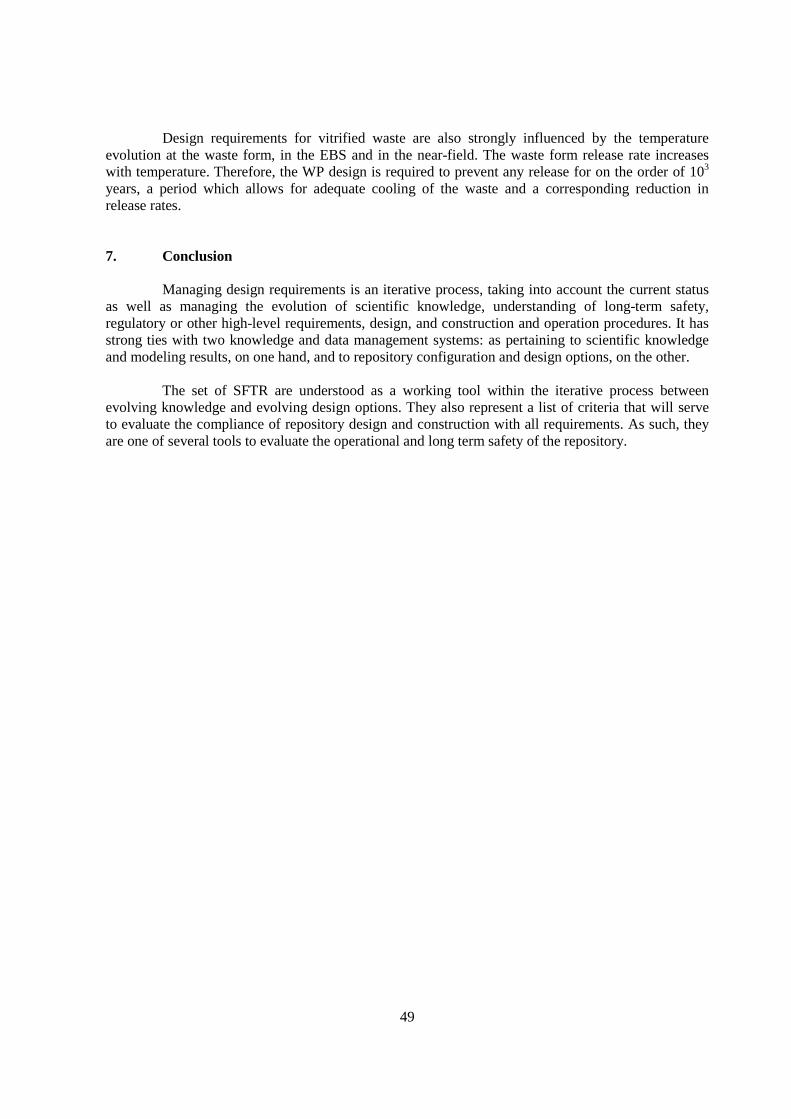
49
Design requirements for vitrified waste are also strongly influenced by the temperatureevolution at the waste form, in the EBS and in the near-field. The waste form release rate increaseswith temperature. Therefore, the WP design is required to prevent any release for on the order of 103
years, a period which allows for adequate cooling of the waste and a corresponding reduction inrelease rates.
7. Conclusion
Managing design requirements is an iterative process, taking into account the current statusas well as managing the evolution of scientific knowledge, understanding of long-term safety,regulatory or other high-level requirements, design, and construction and operation procedures. It hasstrong ties with two knowledge and data management systems: as pertaining to scientific knowledgeand modeling results, on one hand, and to repository configuration and design options, on the other.
The set of SFTR are understood as a working tool within the iterative process betweenevolving knowledge and evolving design options. They also represent a list of criteria that will serveto evaluate the compliance of repository design and construction with all requirements. As such, theyare one of several tools to evaluate the operational and long term safety of the repository.


51
CLOSURE CONCEPT FOR THE MORSLEBEN LLW REPOSITORY FOR RADIOACTIVEWASTE DESIGN OF DRIFT SEALS IN A FORMER SALT MINE
Ralf Mauke, Jürgen WollrathFederal Office for Radiation Protection (BfS, Germany)
Nina Müller-HoeppeDeutsche Gesellschaft zum Bau und Betrieb von Endlagern für Abfallstoffe (DBE, Germany)
1. Introduction
The rock salt and potash mine Bartensleben was selected in 1970 to serve as a repository forlow- and intermediate-level radioactive waste (LILW). Located close to the village of Morslebenapproximately 100 km east of Hanover the facility was named “Morsleben Repository for RadioactiveWaste (Endlager für radioaktive Abfälle Morsleben – ERAM)”. It was designed, constructed andcommissioned between 1972–78. Following studies and the successful demonstration of the disposaltechnologies used, the operating licence was granted in 1981. The disposal of waste was terminated onSeptember 28, 1998. The license for operating the repository originates from the former GermanDemocratic Republic and does not include the license for the closure of the repository. Therefore,according to the Atomic Energy Act (Atomgesetz, AtG) a license application for the closure of therepository has to be prepared by the Federal Office for Radiation Protection (BfS) who became theresponsible operator of the repository after the reunification of Germany in 1990. Presently, BfS plansa closure concept, which matches the long-term performance requirements. It comprises backfillingand sealing of the underground excavations with salt concretes. In the closure concept drift seals ascomponents of an engineered barrier system (EBS) play an important role to guarantee the long-termsafety of the repository.
2. Local geology
The ERAM is located in the structure of the Aller valley zone, named after the small riverAller, covering an area of approximately 50 km2. Tectonically it is a fault structure, due to extensiontectonics, which separates the Lappwald block and the Weferlinger Triassic block. Into the fault zonePermian evaporate strata intruded and accumulated to a plug forming the now existing salt structure.The top of the salt leaching surface is at 140 m below mean sea level and the thickness of the salt bodyvaries between 380 m and 500 m.
The evaporate rocks belong to the Upper Permian Zechstein strata which had been developedin the Central European Basin over an area of more than 700 000 km2. The total salt volume amountsto 153 000 km3. The Zechstein is subdivided into different cycles of salt accumulation. Each cyclestarts with terrigenous, generally clayey deposits (e.g. “salt clays”) overlain by carbonatic and sulfate(anhydrite) rocks followed by a sequence represented by rock salt and in places, by potash salt, capped
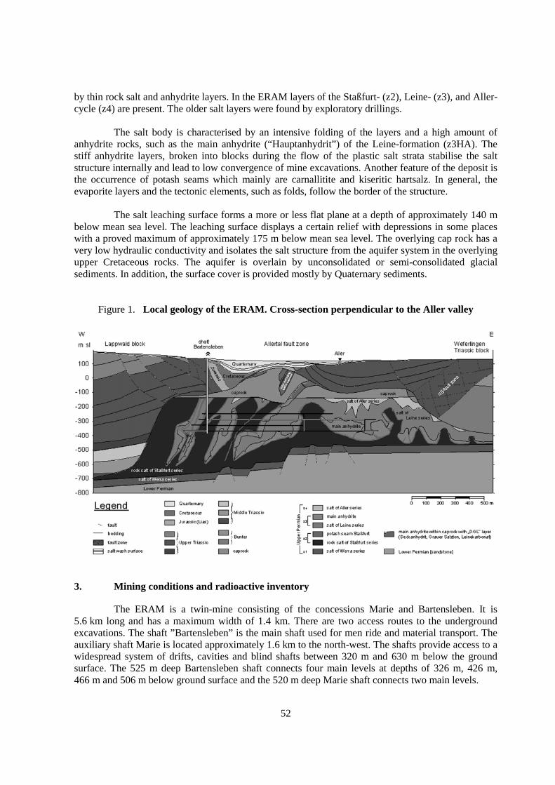
52
by thin rock salt and anhydrite layers. In the ERAM layers of the Staßfurt- (z2), Leine- (z3), and Aller-cycle (z4) are present. The older salt layers were found by exploratory drillings.
The salt body is characterised by an intensive folding of the layers and a high amount ofanhydrite rocks, such as the main anhydrite (“Hauptanhydrit”) of the Leine-formation (z3HA). Thestiff anhydrite layers, broken into blocks during the flow of the plastic salt strata stabilise the saltstructure internally and lead to low convergence of mine excavations. Another feature of the deposit isthe occurrence of potash seams which mainly are carnallitite and kiseritic hartsalz. In general, theevaporite layers and the tectonic elements, such as folds, follow the border of the structure.
The salt leaching surface forms a more or less flat plane at a depth of approximately 140 mbelow mean sea level. The leaching surface displays a certain relief with depressions in some placeswith a proved maximum of approximately 175 m below mean sea level. The overlying cap rock has avery low hydraulic conductivity and isolates the salt structure from the aquifer system in the overlyingupper Cretaceous rocks. The aquifer is overlain by unconsolidated or semi-consolidated glacialsediments. In addition, the surface cover is provided mostly by Quaternary sediments.
Figure 1. Local geology of the ERAM. Cross-section perpendicular to the Aller valley
3. Mining conditions and radioactive inventory
The ERAM is a twin-mine consisting of the concessions Marie and Bartensleben. It is5.6 km long and has a maximum width of 1.4 km. There are two access routes to the undergroundexcavations. The shaft ”Bartensleben” is the main shaft used for men ride and material transport. Theauxiliary shaft Marie is located approximately 1.6 km to the north-west. The shafts provide access to awidespread system of drifts, cavities and blind shafts between 320 m and 630 m below the groundsurface. The 525 m deep Bartensleben shaft connects four main levels at depths of 326 m, 426 m,466 m and 506 m below ground surface and the 520 m deep Marie shaft connects two main levels.
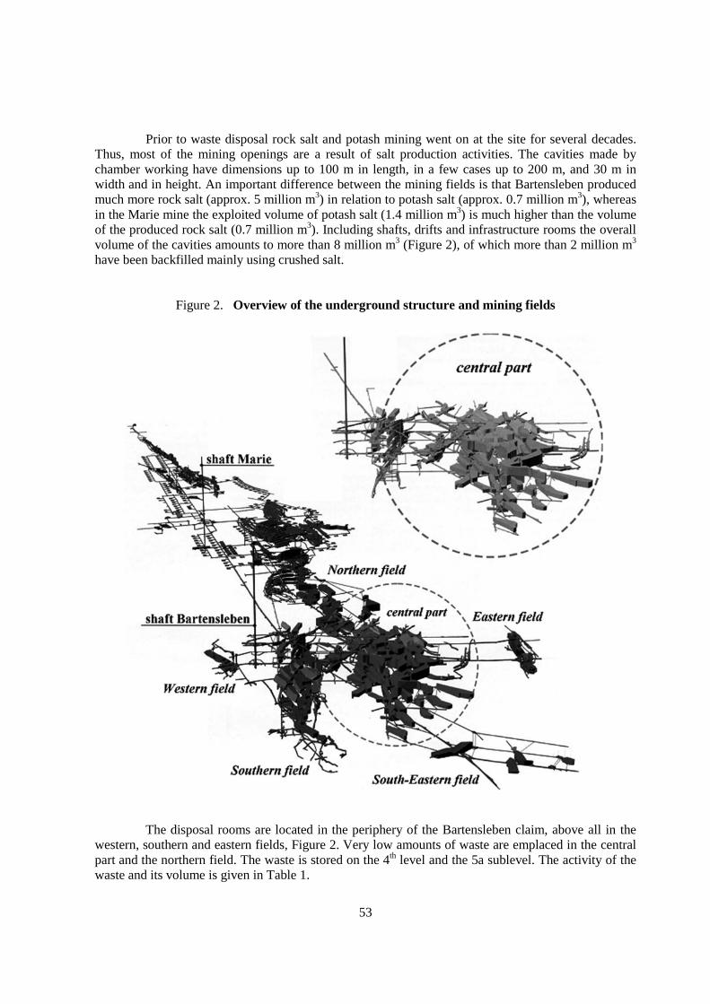
53
Prior to waste disposal rock salt and potash mining went on at the site for several decades.Thus, most of the mining openings are a result of salt production activities. The cavities made bychamber working have dimensions up to 100 m in length, in a few cases up to 200 m, and 30 m inwidth and in height. An important difference between the mining fields is that Bartensleben producedmuch more rock salt (approx. 5 million m3) in relation to potash salt (approx. 0.7 million m3), whereasin the Marie mine the exploited volume of potash salt (1.4 million m3) is much higher than the volumeof the produced rock salt (0.7 million m3). Including shafts, drifts and infrastructure rooms the overallvolume of the cavities amounts to more than 8 million m3 (Figure 2), of which more than 2 million m3
have been backfilled mainly using crushed salt.
Figure 2. Overview of the underground structure and mining fields
The disposal rooms are located in the periphery of the Bartensleben claim, above all in thewestern, southern and eastern fields, Figure 2. Very low amounts of waste are emplaced in the centralpart and the northern field. The waste is stored on the 4th level and the 5a sublevel. The activity of thewaste and its volume is given in Table 1.
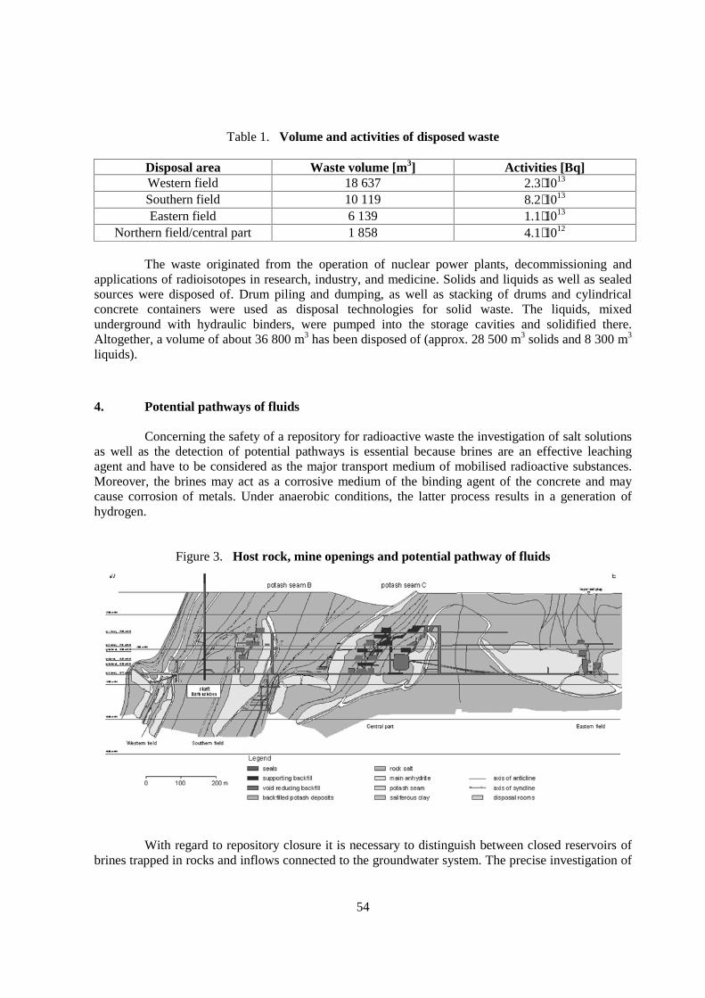
54
Table 1. Volume and activities of disposed waste
Disposal area Waste volume [m3] Activities [Bq]Western field 18 637 2.3⋅1013
Southern field 10 119 8.2⋅1013
Eastern field 6 139 1.1⋅1013
Northern field/central part 1 858 4.1⋅1012
The waste originated from the operation of nuclear power plants, decommissioning andapplications of radioisotopes in research, industry, and medicine. Solids and liquids as well as sealedsources were disposed of. Drum piling and dumping, as well as stacking of drums and cylindricalconcrete containers were used as disposal technologies for solid waste. The liquids, mixedunderground with hydraulic binders, were pumped into the storage cavities and solidified there.Altogether, a volume of about 36 800 m3 has been disposed of (approx. 28 500 m3 solids and 8 300 m3
liquids).
4. Potential pathways of fluids
Concerning the safety of a repository for radioactive waste the investigation of salt solutionsas well as the detection of potential pathways is essential because brines are an effective leachingagent and have to be considered as the major transport medium of mobilised radioactive substances.Moreover, the brines may act as a corrosive medium of the binding agent of the concrete and maycause corrosion of metals. Under anaerobic conditions, the latter process results in a generation ofhydrogen.
Figure 3. Host rock, mine openings and potential pathway of fluids
With regard to repository closure it is necessary to distinguish between closed reservoirs ofbrines trapped in rocks and inflows connected to the groundwater system. The precise investigation of

55
active brine occurrences as well as of potential pathways is important with respect to brine inflowsduring the post-closure phase and the outflow of contaminated solutions. Besides the shafts potentialpathways may occur along potash seams and enclaves of competent rock with a tendency to brittlefailure, e.g. anhydrite blocks.
Recently active brine inflows into the mine openings have been low. Thus, one location issituated far from the disposal areas in the Marie mine and has an inflow rate of about 10 m3/a. Adropping location with an inflow rate of about 1 m3/a is situated on the first level of the central part ofthe Bartensleben mine. The chemical composition of the NaCl-saturated, Mg-rich solutions have beennearly constant and prove a contact with potash salts.
Concerning potential pathways special attention has to be paid to the main anhydrite (z3HA)and the overlain potash seam C. These geological units connect the cap rock to the excavationdisturbed zone of the mine openings of the central part and may act as future pathways for fluids(Figure 3).
5. Closure concept and long-term safety objectives
The “Safety Criteria for the Disposal of Radioactive Waste in a Mine” qualitatively specifymeasures to be taken in order to agree with the long-term safety objectives of disposal. The long-termsafety objectives regarded in general mainly focus on radiological safety. i.e.:
• protecting the biosphere against harmful effects of radionuclide release;• avoiding criticality.
In the case of the ERAM, however, due to the large void volume classical conventional long-term safety objectives such as:
• limiting ground surface subsidence;• protecting groundwater against release of conventional pollutants.
have to be considered additionally [1]. The safety assessments distinguish two main groups ofscenarios [2]. In the first group of scenarios no fluid inflow into the mine openings does occur (dryrepository condition) whereas in the second group of scenarios fluids enter the mine openings and mayget into contact with the radioactive waste (wet repository condition).
The closure concept, which is presently being evaluated by the licensing authority, relies ona comprehensive backfilling of all mine openings (extensive backfill closure concept). The mineopenings are backfilled with salt concretes to stabilise the underground structure, to limit leachingprocesses in case of unsaturated brine inflow and to seal the disposal areas.
According to safety measures agreed upon internationally, the multi-barrier concept isincluded in the closure concept, i.e. safety is not considered to be guaranteed only by one barrier, i.e.the geological formation. In general a multi-barrier system may include the waste form, the packagingas well as backfilling and sealing measures. By this means, the waste will be isolated by a system ofparallel or interlocking natural and technical barriers.
In the case of the ERAM tight shaft seals are planned as to limit the volumetric flow rate ofbrine passing the shafts to a negligible extent. Besides the comprehensive backfill importantcomponents of the closure concept, however, the drift seals separate the disposal areas (eastern,
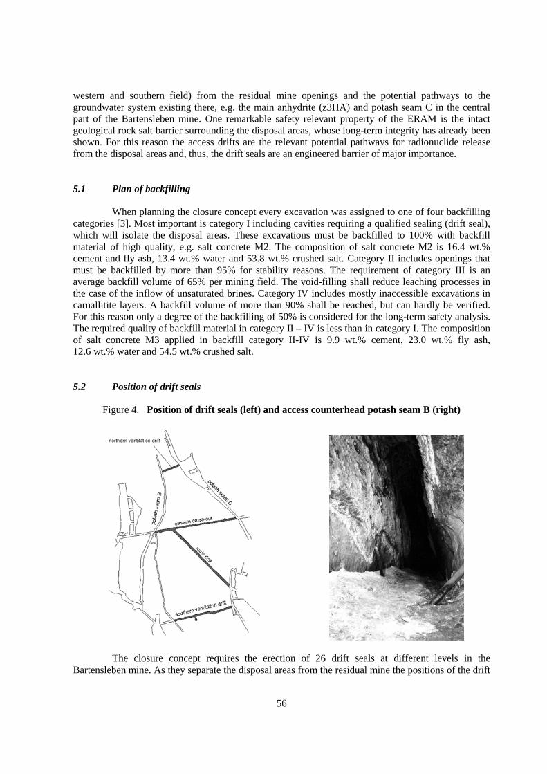
56
western and southern field) from the residual mine openings and the potential pathways to thegroundwater system existing there, e.g. the main anhydrite (z3HA) and potash seam C in the centralpart of the Bartensleben mine. One remarkable safety relevant property of the ERAM is the intactgeological rock salt barrier surrounding the disposal areas, whose long-term integrity has already beenshown. For this reason the access drifts are the relevant potential pathways for radionuclide releasefrom the disposal areas and, thus, the drift seals are an engineered barrier of major importance.
5.1 Plan of backfilling
When planning the closure concept every excavation was assigned to one of four backfillingcategories [3]. Most important is category I including cavities requiring a qualified sealing (drift seal),which will isolate the disposal areas. These excavations must be backfilled to 100% with backfillmaterial of high quality, e.g. salt concrete M2. The composition of salt concrete M2 is 16.4 wt.%cement and fly ash, 13.4 wt.% water and 53.8 wt.% crushed salt. Category II includes openings thatmust be backfilled by more than 95% for stability reasons. The requirement of category III is anaverage backfill volume of 65% per mining field. The void-filling shall reduce leaching processes inthe case of the inflow of unsaturated brines. Category IV includes mostly inaccessible excavations incarnallitite layers. A backfill volume of more than 90% shall be reached, but can hardly be verified.For this reason only a degree of the backfilling of 50% is considered for the long-term safety analysis.The required quality of backfill material in category II – IV is less than in category I. The compositionof salt concrete M3 applied in backfill category II-IV is 9.9 wt.% cement, 23.0 wt.% fly ash,12.6 wt.% water and 54.5 wt.% crushed salt.
5.2 Position of drift seals
Figure 4. Position of drift seals (left) and access counterhead potash seam B (right)
The closure concept requires the erection of 26 drift seals at different levels in theBartensleben mine. As they separate the disposal areas from the residual mine the positions of the drift

57
seals are defined by the geometric structure of the mine as well as by geological conditions. Highquality sealing of large cavities has to be avoided due to technical problems and a large excavationdisturbed zone (EDZ). Additionally, the drift seals have to be placed in rock salt to avoid leachingprocesses. Fig.4 shows the drift seal placed between potash seams B (southern field, disposal area) andC (central part, potential pathway) separating the southern field from the central part. The drift seal inthe northern ventilation drift on the 2nd level is the most severe location, as the thickness of the intactrock salt layer between potash seams B and C is only about 25 m. Thus, the drift seal’s length is short.In addition, potash seams B and C were excavated extensively in the past, Figure 4. For this reasonaccess to the drift seal’s position is complicated.
6. Drift seals
Basic requirements on the drift seals arise from the long-term safety analysis [4], [5] as wellas from restricted length and limited access. To assure agreement with the radiological long-termsafety objectives the hydraulic resistance of the drift seals appears to be the crucial property.Restricted length of drift seals leads to a design, providing the drift seals serve as both seal andabutment to achieve a maximum of hydraulic resistance. Due to limited access the construction has tobe simple.
Regarding the hydraulic resistance the drift seals consist of three main elements, the sealingbody, the contact zone between sealing body and surrounding rock salt and the excavation disturbedzone (EDZ). Laboratory experiments indicate that the salt concrete will attain an initial permeability ofat least 10-18 m2 and in the design of the drift seals this value has become the main requirement. Brinemigration through the seals might degrade their hydraulic behaviour due to chemical reactions,however. This could not be avoided because no material has been known that is chemically stable toall possible brines getting into contact with the seals. The chemical constitution of the brine dependson its flow path and could not be pre-determined due to the geometrical complexity of the mine andthe salt structure.
Laboratory experiments and model calculations indicate that the hydraulic conductivity of aseal will increase depending on the amount and chemical constitution of the brine migrating through it.Penetration of the seals starts when a significant hydraulic gradient has established between thedisposal areas and the remaining part of the mine. Due to the initially low permeability of the sealsmodel calculations based on laboratory experiments show that in the worst case constitution of thebrine they will keep their function for at least some 5 000 years [6] after having got in contact withthat brine. The degradation of the drift seals has been taken into account in the safety analysis and hasbeen shown to be tolerable.
6.1 Design of drift seals
Every drift seal consists of segments, each of them 25 ±5 m long, of which several may bearranged one behind the other in order to meet the requirements. At minimum a drift seal consists ofone segment, e.g. the drift seal in the northern ventilation drift (Figure 4). The length of segments isrestricted to reduce the impact from geological movements as well as restraint stresses due to the heatof hydration (Figure 5). To assess the influence of geological movements the dimensions of smallanhydrite blocks in the ERAM were looked upon a site specific natural analogue.
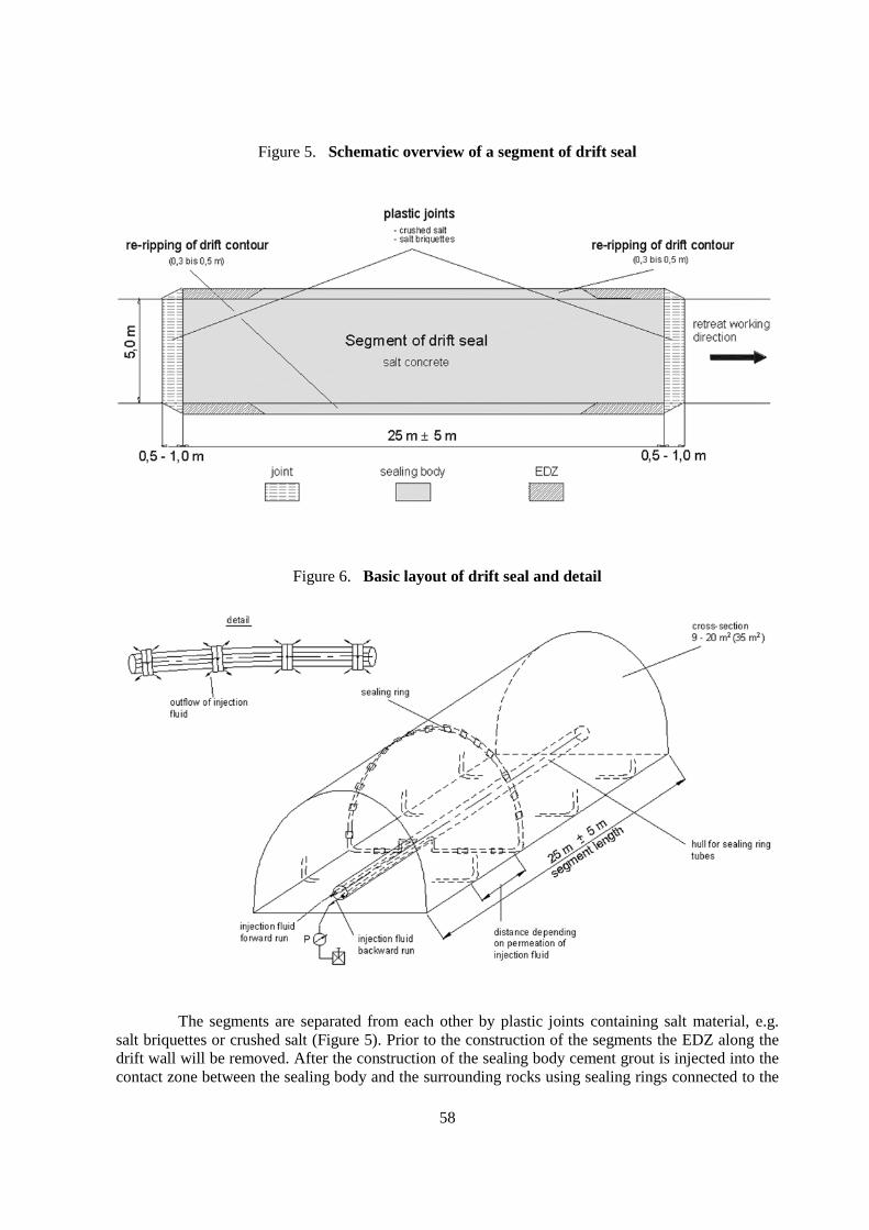
58
Figure 5. Schematic overview of a segment of drift seal
Figure 6. Basic layout of drift seal and detail
The segments are separated from each other by plastic joints containing salt material, e.g.salt briquettes or crushed salt (Figure 5). Prior to the construction of the segments the EDZ along thedrift wall will be removed. After the construction of the sealing body cement grout is injected into thecontact zone between the sealing body and the surrounding rocks using sealing rings connected to the

59
pump (forward/backward run) by a hull for sealing ring tubes, which will be over-drilled after havingcompleted the injection process (Figure 6). The borehole itself is backfilled by salt concrete M2afterwards. Thus, each segment is provided with a ring seal and is pre-stressed sufficiently towithstand the load of future fluid pressure. The whole structure serves as a seal and as an abutmentleading to a maximum of hydraulic resistance in case of restricted length. By this force-transferringdesign relative sliding between the sealing body and the surrounding rocks is excluded and thetightness of the contact zone is guaranteed.
6.2 Sealing body material
As already mentioned above the salt concrete M2 contains fly ash as a relevant ingredient.Fly ash particles are spherical and most of them are smaller in size then cement particles. Thischaracteristic property allows the fresh concrete to have a good flowability/workability, which is ofmajor importance due to restricted access to the drift seal’s position. The concrete is used in the senseof a mass concrete. Consequently, special attention has to be paid to hydration heat during theconstruction phase to avoid crack evolution. A maximum adiabatic temperature rise of 47.7°C wasmeasured experimentally.
Figure 7. Failure and dilatancy bound of salt concrete M2 in comparison with rock salt
Dilatancy bounds of the salt concrete M2 were determined by laboratory tests to serve as acriterion for assessing crack evolution due to mechanical and restraint stresses. Dilatancy bounds ofsalt concrete M2 are given in Figure 7 in comparison to the failure bound and dilatancy bound of rocksalt. The dilatancy bounds of salt concrete M2 exceed the dilatancy bound of rock salt, however, theywere found to be strain rate dependent. Strain rates investigated up to now are 10-5 s-1 and 10-6 s-1. In
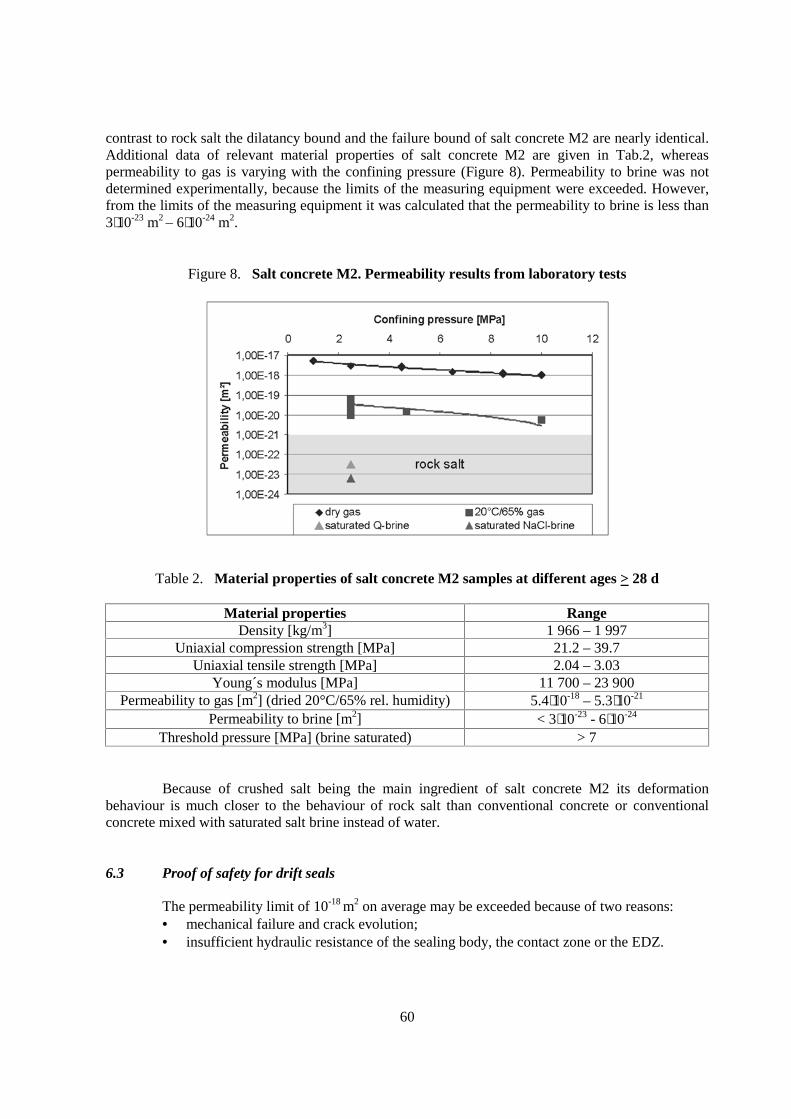
60
contrast to rock salt the dilatancy bound and the failure bound of salt concrete M2 are nearly identical.Additional data of relevant material properties of salt concrete M2 are given in Tab.2, whereaspermeability to gas is varying with the confining pressure (Figure 8). Permeability to brine was notdetermined experimentally, because the limits of the measuring equipment were exceeded. However,from the limits of the measuring equipment it was calculated that the permeability to brine is less than3⋅10-23 m2 – 6⋅10-24 m2.
Figure 8. Salt concrete M2. Permeability results from laboratory tests
Table 2. Material properties of salt concrete M2 samples at different ages > 28 d
Material properties RangeDensity [kg/m3] 1 966 – 1 997
Uniaxial compression strength [MPa] 21.2 – 39.7Uniaxial tensile strength [MPa] 2.04 – 3.03
Young´s modulus [MPa] 11 700 – 23 900Permeability to gas [m2] (dried 20°C/65% rel. humidity) 5.4⋅10-18 – 5.3⋅10-21
Permeability to brine [m2] < 3⋅10-23 - 6⋅10-24
Threshold pressure [MPa] (brine saturated) > 7
Because of crushed salt being the main ingredient of salt concrete M2 its deformationbehaviour is much closer to the behaviour of rock salt than conventional concrete or conventionalconcrete mixed with saturated salt brine instead of water.
6.3 Proof of safety for drift seals
The permeability limit of 10-18 m2 on average may be exceeded because of two reasons:• mechanical failure and crack evolution;• insufficient hydraulic resistance of the sealing body, the contact zone or the EDZ.
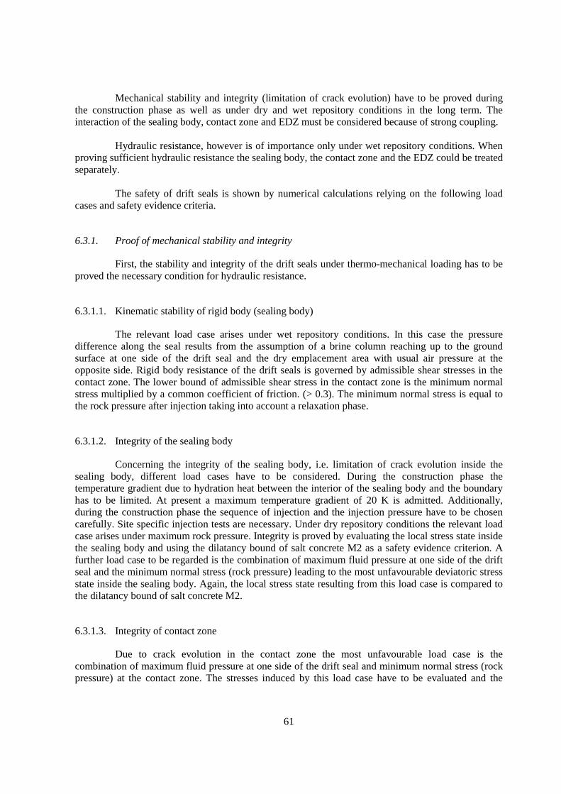
61
Mechanical stability and integrity (limitation of crack evolution) have to be proved duringthe construction phase as well as under dry and wet repository conditions in the long term. Theinteraction of the sealing body, contact zone and EDZ must be considered because of strong coupling.
Hydraulic resistance, however is of importance only under wet repository conditions. Whenproving sufficient hydraulic resistance the sealing body, the contact zone and the EDZ could be treatedseparately.
The safety of drift seals is shown by numerical calculations relying on the following loadcases and safety evidence criteria.
6.3.1. Proof of mechanical stability and integrity
First, the stability and integrity of the drift seals under thermo-mechanical loading has to beproved the necessary condition for hydraulic resistance.
6.3.1.1. Kinematic stability of rigid body (sealing body)
The relevant load case arises under wet repository conditions. In this case the pressuredifference along the seal results from the assumption of a brine column reaching up to the groundsurface at one side of the drift seal and the dry emplacement area with usual air pressure at theopposite side. Rigid body resistance of the drift seals is governed by admissible shear stresses in thecontact zone. The lower bound of admissible shear stress in the contact zone is the minimum normalstress multiplied by a common coefficient of friction. (> 0.3). The minimum normal stress is equal tothe rock pressure after injection taking into account a relaxation phase.
6.3.1.2. Integrity of the sealing body
Concerning the integrity of the sealing body, i.e. limitation of crack evolution inside thesealing body, different load cases have to be considered. During the construction phase thetemperature gradient due to hydration heat between the interior of the sealing body and the boundaryhas to be limited. At present a maximum temperature gradient of 20 K is admitted. Additionally,during the construction phase the sequence of injection and the injection pressure have to be chosencarefully. Site specific injection tests are necessary. Under dry repository conditions the relevant loadcase arises under maximum rock pressure. Integrity is proved by evaluating the local stress state insidethe sealing body and using the dilatancy bound of salt concrete M2 as a safety evidence criterion. Afurther load case to be regarded is the combination of maximum fluid pressure at one side of the driftseal and the minimum normal stress (rock pressure) leading to the most unfavourable deviatoric stressstate inside the sealing body. Again, the local stress state resulting from this load case is compared tothe dilatancy bound of salt concrete M2.
6.3.1.3. Integrity of contact zone
Due to crack evolution in the contact zone the most unfavourable load case is thecombination of maximum fluid pressure at one side of the drift seal and minimum normal stress (rockpressure) at the contact zone. The stresses induced by this load case have to be evaluated and the

62
minimum stress component at the contact zone is compared to fluid pressure, i.e. the fluid criterionσ1 > pfluid is applied to prove safety.
6.3.2. Proof of hydraulic resistance of drift seals
After having shown the mechanical stability and integrity of drift seal the proof of sufficienthydraulic resistance has to be performed next step. As a first approach the proof will separately becarried out for the sealing body, the contact zone and the EDZ. In case of the sealing body and thecontact zone the initial hydraulic resistance and the increasing permeability due to corrosion processes(long-term stability) have to be regarded. In the EDZ no corrosion will take place. As a permeability of10-18 m2 is required on average, a higher permeability of the EDZ may be compensated by a lowerpermeability of the sealing body taking into account the volumetric flow rate of the whole system. In afirst approach, however, the three elements of the drift seal are considered separately.
6.3.2.1. Limitation of flow rate migrating through sealing body
This load case assumes maximum brine pressure at one side of the drift seal and usual airpressure at the opposite side resulting in the maximum hydraulic gradient possible. An initialpermeability k < 10-18 m2 leads to a release of radionuclide that is sufficiently low. In additionlong-term stability has been proven as corrosion due to NaCl or MgCl2 saturated brines migratingthrough the seals proceeds sufficiently slowly during the required time period. As laboratory testsshowed that the permeability of salt concrete M2 fulfils the requirement k < 10-18 m2 (Table 2,Figure 8) the required limited flow rate migrating through the sealing body and consequently sufficientlong-term stability can be proved.
6.3.2.2. Limitation of flow rate migrating through the contact zone
The relevant load case for the contact zone is identical to that of the sealing body. Evidently,the same requirement of k < 10-18 m2 is the safety evidence criterion for the contact zone. Accordingto German technical regulations in civil engineering [7] investigations on comparable structures arenecessary for assessing the hydraulic resistance of contact zones. To gain a reliable data basis in situtests are planned in the Asse salt mine investigating the contact zone of a 10-year old salt concrete sealby permeability tests, hydraulic fracturing and ultrasonic fault analysis. Additionally, mechanical andhydraulic properties of core samples from the Asse seal and the contact zone will be examined bylaboratory tests, to get a better knowledge on the quality of salt concrete achieved in situ and itsadhesion to the salt rock contour. If it finally turns out that the required permeability of 10-18 m2 isachieved in situ, the corrosion process in the contact zone is sufficiently slow and long-term stabilityof the contact zone is guaranteed during the required time period.
6.3.2.3 Limitation of flow rate migrating through the EDZ
The relevant load case for the EDZ assumes maximum brine pressure at one side of the driftseal and usual air pressure at the opposite side resulting in the maximum hydraulic gradient. Due to theposition of the drift seals saturated brine is assumed and therefore the long-term stability of the EDZ isautomatically given. Thus, the only requirement concerning the EDZ is the limitation of permeabilityto k < 10-18 m2. In the ERAM permeability measurements in trimmed drifts showed values of 5⋅10-17
m2 – 1⋅10-20 m2. The EDZ of the up to 70-year-old drifts will be removed before building the drift

63
seals. Thus, in the case of the EDZ a permeability of 10-18 m2 on average seems to be obtainable. In thecase of the EDZ permeability exceeds the limit value slightly. This can be compensated by a lowerpermeability of the sealing body because there is no danger of corrosion processes in the EDZ.
7. Summary and Conclusion
In this paper the basis of drift seals conception is given including a comprehensive analysisof the site specific situation and an overview of the closure concept. The requirements on drift sealsand backfill respectively sealing material rely on inputs from long-term safety analysis. These aspectsaltogether lead to a simple and robust design of drift seals associated with a plausible way of provingthe drift seals’ compliance with the requirements.
Presently, the termination of concept planning is scheduled in 2003 followed by the begin ofthe licensing procedure.
References
[1] Preuss J., Eilers G., Mauke, R. et al. (2002): Post Closure Safety of the Morsleben Repository,WM´02 Conference, February 24-28, 2002, Tucson, AZ, USA.
[2] Preuss J., Müller-Hoeppe N., Schrimpf C. (2000): The Interaction of the Evidence of Postclosure Safety and Requirements to Backfill Materials for the Morsleben Repository, Proc.DISTEC 2000, September 4-6, 2000, Berlin, Germany.
[3] Köster R., Maiwald-Rietmann H.U., Laske, D. (2002): Development of backfill materials inan underground salt repository, 6. Int. Workshop on Design and Construction of FinalRepositories – Backfilling in Radioactive Waste Disposal, March 11-13, 2002, Brussels,Belgium.
[4] Resele G., Oswald S., Wollrath J. et al. (2000): Morsleben nuclear waste repository –probabilistic safety assessment for the concept of extensive backfill, Proc. DISTEC 2000,September 4-6, 2000, Berlin, Germany.
[5] Boese B.; Strock R.; Brenner, J. et al. (2000): Closure of the final repository of Morslebenaccording to the pore reservoir concept and the sealing concept and model calculations for thelong-term safety, Proc. DISTEC 2000, September 4-6, 2000, Berlin, Germany.
[6] Ranft M., Wollrath J., (2002): Time Scales in the Long-Term Safety Assessment of theMorsleben Repository, Germany, OECD/NEA Workshop on Handling of Time Scales inAssessing Post Closure Safety, April 16-18, 2002, Paris, France.
[7] DAfStb (1996): Betonbau beim Umgang mit wassergefährdenden Stoffen, DAfStb-Richtlinie,Germany.


65
CROP – A PROJECT FOR COMPARATIVE DESCRIPTION OF NATIONAL CONCEPTSFOR DISPOSAL OF RADIOACTIVE WASTE
Roland PuschGeodevelopment AB, Sweden
Christer SvemarSKB, Sweden
1. Scope
Nine partners representing Sweden (SKB), Belgium (SCK-CEN), Finland (POSIVA), France(Andra), Germany (GRS), Switzerland (NAGRA), Spain (ENRESA), Canada (OPG), and the US(DOECBFO) participate in the EC-supported project CROP, which is the synonym for ClusterRepository Project and aims at describing the various repository concepts for identifying similaritiesand differences. The ambition is to assist designers and modelers in the development of the respectiveconcepts.
Design, construction and instrumentation of underground laboratories (URLs) andforthcoming repositories as well as modeling the engineered performance of national repositoryconcepts in crystalline rock, salt and clay are defined and compared. The depth of location of therepositories is different – 250 to 1000 m – and also the design: the multibarrier philosophy is proposedfor disposal in all types of rock but for salt the geological medium is considered to be the majorbarrier. The minimum time for effective isolation of the waste differs among national programs (E4 toE6 years) and so is the effort of modeling physical and chemical degradation of the engineered barriersystem (EBS), which consists of canisters, embedding buffer and backfill, and plugs. CROP isfocusing on the buffer and backfill and shaft, tunnel and borehole seals including plugs.
The temperature in the near-field is a most important factor for the repository performance. Itwill be in the interval 90-110oC for crystalline rock and clay, and up to 200oC for salt in the closevicinity of the waste according to the concepts, attenuating with increased distance from it. The heatand temperature gradient affects the groundwater flow and rock strain and thereby the evolution of theEBS in the first few hundred years and they are determinants of the chemical stability and hencerequired dimensions of the engineered barriers. Both the short- and long-term performance of the EBSare significantly affected by the groundwater chemistry.

66
2. Design (WP1)
2.1 Location
Structure, hydrology and geochemistry, rock stress conditions and seismicity, are technicalfactors that affect the site selection. In principle, crystalline rock, salt and clay shale show similarstructural patterns with major discontinuities dividing the rock mass into large blocks that contain lessimportant discontinuities of different size. They have different properties in the three geological mediawith respect to mechanical and hydraulic behaviour. Only major discontinuities – fracture zones ingranite and claystone and clay shale and weak, water-bearing zones like clay seams in salt – aredeterminants of the location and orientation of repositories. They may be equally frequent in all rocktypes and need to be identified by geological mapping, deep borings and geophysical investigationsfor working out structural, geohydrological and geochemical models [1,2]. Plastic clay shows adifferent structure by being more homogeneous.
The principal stresses and their mutual ratios determine the mechanical stability of the near-field rock and hence have an impact on the location of a repository. This is exemplified by theconditions in the central part of the Canadian shield where spalling and local rock failure occur atexcavation deeper than about 300 m. Figure 1 shows examples of the interaction of a repository andtypical crystalline and salt rock structures. Tectonically induced shearing takes place primarily alongmajor weaknesses, and differences in piezometric conditions in those in crystalline and brittle claycause groundwater flow in the system, leaving the rock matrix more or less with stagnant water.
Figure 1. Schematic picture of underground research facilities interacting with typical systemsof discontinuities. Left: Fracture zones in granite controlling large-scale groundwater flow and
deformation (Stripa URL). Right: Asse salt anticline with large internal discontinuitiesinfluencing large-scale strain

67
2.2 Geometry and layout
The amount of waste, spent fuel and reprocessed waste, and their distribution in therepositories determine the heat evolution and hence the selected repository geometry, i.e. the spacingof tunnels and deposition holes. Waste disposal is planned to be made in different ways in the conceptsdepending on the rock stability and behaviour as well as on cost. Large rooms with many canistersembedded in clay buffer or crushed salt is an option for crystalline rock and salt, respectively. Longsub-horizontal tunnels with rows of axially centered and oriented canisters is proposed for crystallinerock and claystone or plastic clay (NAGRA, ENRESA, OPG, SCK-CEN), and vertical depositionholes bored perpendicularly from the floor of horizontal tunnels with one or several buffer-embeddedcanisters in the holes is a candidate concept for SKB (KBS-3), POSIVA and Andra in crystalline rock.The shape and size of the holes and tunnels are selected on the basis of stability estimates and on therequired dimensions of EBS components.
2.3 Rock stability
The stress/strain properties of the rock control the stability of the near-field rock. They arescale-dependent and related to the rock structure. For good granite and gneiss the unconfinedcompressive strength of core samples is in the interval 150 to 300 MPa but the volume-dependentfrequency of discontinuities in the matrix significantly affects the bulk strength and deformationmoduli of the rock mass. For claystone and plastic clay the corresponding values are much lower,which means that due respect has to be paid to the size and orientation of deposition holes and tunnelsfor avoiding unstable conditions. Creep is of very limited importance for crystalline rock but may beof significance for clay. In clays large strain may lead to failure and permanently enhanced hydraulicconductivity. For plastic clay and salt, creep is of primary importance because it has the beneficialfunction to cause convergence of rooms and drifts and perfect homogeneity of the repository rock.
Figure 2 illustrates the general features of some repository concepts. For the case ofdeposition holes bored from TBM tunnels at 500 m depth, the floor around the deposition holes maybe in a critical stress situation (Figures 3a and b). Even if macroscopic failure does not take placecomprehensive fine-fissuring may occur close to the holes yielding “excavation-disturbance” and anincrease in hydraulic conductivity [3].
Figure 2. Examples of repository concepts
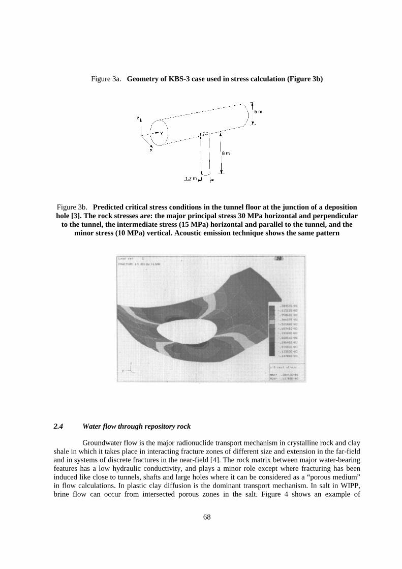
68
Figure 3a. Geometry of KBS-3 case used in stress calculation (Figure 3b)
Figure 3b. Predicted critical stress conditions in the tunnel floor at the junction of a depositionhole [3]. The rock stresses are: the major principal stress 30 MPa horizontal and perpendicular
to the tunnel, the intermediate stress (15 MPa) horizontal and parallel to the tunnel, and theminor stress (10 MPa) vertical. Acoustic emission technique shows the same pattern
2.4 Water flow through repository rock
Groundwater flow is the major radionuclide transport mechanism in crystalline rock and clayshale in which it takes place in interacting fracture zones of different size and extension in the far-fieldand in systems of discrete fractures in the near-field [4]. The rock matrix between major water-bearingfeatures has a low hydraulic conductivity, and plays a minor role except where fracturing has beeninduced like close to tunnels, shafts and large holes where it can be considered as a “porous medium”in flow calculations. In plastic clay diffusion is the dominant transport mechanism. In salt in WIPP,brine flow can occur from intersected porous zones in the salt. Figure 4 shows an example of
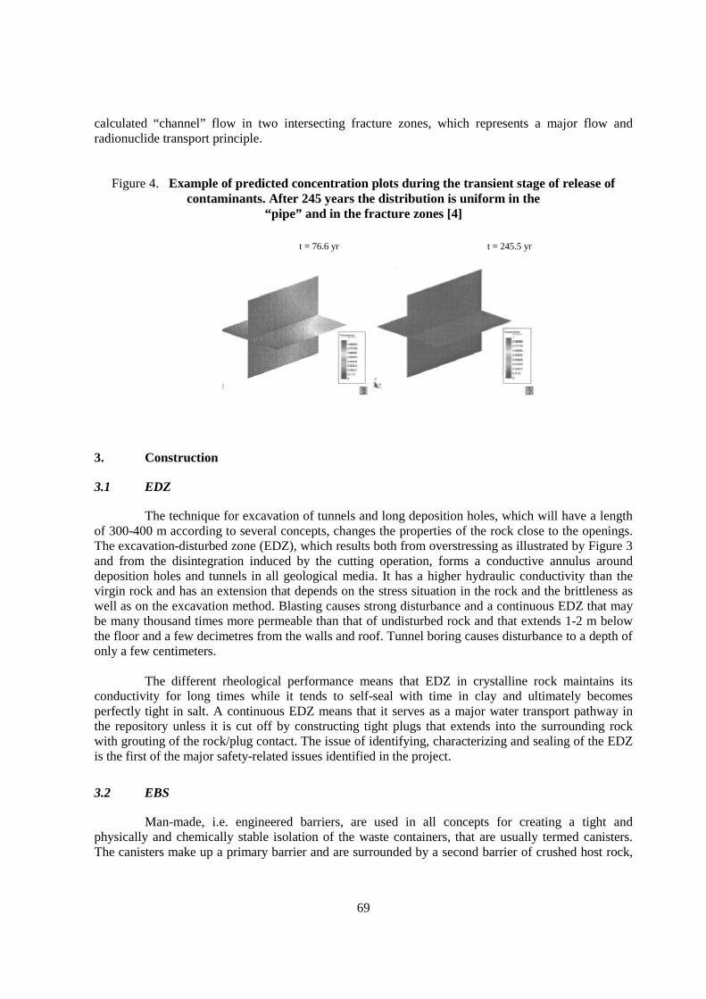
69
calculated “channel” flow in two intersecting fracture zones, which represents a major flow andradionuclide transport principle.
Figure 4. Example of predicted concentration plots during the transient stage of release ofcontaminants. After 245 years the distribution is uniform in the
“pipe” and in the fracture zones [4]
3. Construction
3.1 EDZ
The technique for excavation of tunnels and long deposition holes, which will have a lengthof 300-400 m according to several concepts, changes the properties of the rock close to the openings.The excavation-disturbed zone (EDZ), which results both from overstressing as illustrated by Figure 3and from the disintegration induced by the cutting operation, forms a conductive annulus arounddeposition holes and tunnels in all geological media. It has a higher hydraulic conductivity than thevirgin rock and has an extension that depends on the stress situation in the rock and the brittleness aswell as on the excavation method. Blasting causes strong disturbance and a continuous EDZ that maybe many thousand times more permeable than that of undisturbed rock and that extends 1-2 m belowthe floor and a few decimetres from the walls and roof. Tunnel boring causes disturbance to a depth ofonly a few centimeters.
The different rheological performance means that EDZ in crystalline rock maintains itsconductivity for long times while it tends to self-seal with time in clay and ultimately becomesperfectly tight in salt. A continuous EDZ means that it serves as a major water transport pathway inthe repository unless it is cut off by constructing tight plugs that extends into the surrounding rockwith grouting of the rock/plug contact. The issue of identifying, characterizing and sealing of the EDZis the first of the major safety-related issues identified in the project.
3.2 EBS
Man-made, i.e. engineered barriers, are used in all concepts for creating a tight andphysically and chemically stable isolation of the waste containers, that are usually termed canisters.The canisters make up a primary barrier and are surrounded by a second barrier of crushed host rock,
t = 76.6 yr t = 245.5 yr

70
clay (buffer) or cement. Tunnels and shafts are sealed with crushed host rock, clay-based backfills andplugs.
Canisters can be very corrosion-resistant, like SKB’s iron/copper containers, or of limitedchemical stability as exemplified by steel canisters. They have different length/diameter ratios, whichhas an impact on their strength, deformability and weight. The chemical interaction between bufferand metal is also different and can lead to cation exchange and precipitation, which may alter therheological properties of the buffer.
Buffers and backfills are of different types. For salt, crushed salt and salt blocks will be usedfor backfilling and sealing, and for crystalline rock and clay, smectitic clay is a primary candidate.Prefabricated dense smectitic clay blocks with a dry density of up to 2000 kg/m3 and of handable size,like the ones used by ENRESA in the Febex project, can be prepared in large amounts using ordinarycompaction facilities, but also very big blocks can be prepared for isolating canisters of the KBS-3type (Figure 5). NAGRA’s concept of placing canisters in a row in long tunnels (holes) implies thatthey rest on a foundation of highly compacted clay blocks while the rest of the space is filled with verydense pellets of the same smectite clay blown in or “augered”. Uptake of water from the rock will leadto expansion of the clay components in all the concepts and ultimately to an equilibrium state with thecanisters embedded by homogeneous, practically impermeable clay.
Figure 5. Ring-shaped block for surrounding a canister (Clay Technology AB). Weight about 2tons, diameter 1.75 m and height 0.4 m. The block was made by uniaxial
compaction under 100 MPa pressure
The ultimately water-saturated smectitic clay materials have a hydraulic conductivity that isillustrated by Figure 6. For saturation with salt water the conductivity is almost the same as for freshwater when the density exceeds about 1900 kg/m3 but for lower densities strongly brackish and saltwater give a significantly higher conductivity and lower swelling pressure. A very important fact isthat smectite clay treated with Ca and natural Ca bentonites do not have a stable physical form atlower densities than about 1600 kg/m3 because of the poor gel formation potential. Their hydraulicconductivity is much higher than that of Na smectite.
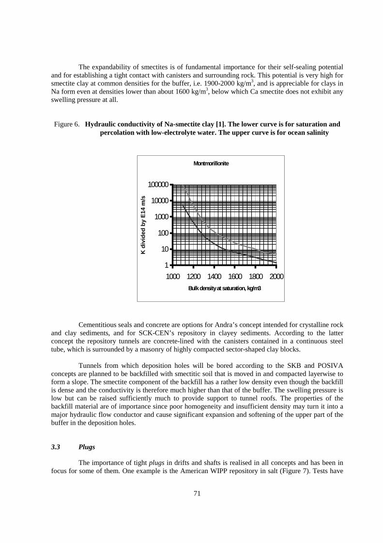
71
The expandability of smectites is of fundamental importance for their self-sealing potentialand for establishing a tight contact with canisters and surrounding rock. This potential is very high forsmectite clay at common densities for the buffer, i.e. 1900-2000 kg/m3, and is appreciable for clays inNa form even at densities lower than about 1600 kg/m3, below which Ca smectite does not exhibit anyswelling pressure at all.
Figure 6. Hydraulic conductivity of Na-smectite clay [1]. The lower curve is for saturation andpercolation with low-electrolyte water. The upper curve is for ocean salinity
Montmorillonite
1
10
100
1000
10000
100000
1000 1200 1400 1600 1800 2000
Bulk density at saturation, kg/m3
K d
ivid
ed b
y E
14 m
/s
Cementitious seals and concrete are options for Andra’s concept intended for crystalline rockand clay sediments, and for SCK-CEN’s repository in clayey sediments. According to the latterconcept the repository tunnels are concrete-lined with the canisters contained in a continuous steeltube, which is surrounded by a masonry of highly compacted sector-shaped clay blocks.
Tunnels from which deposition holes will be bored according to the SKB and POSIVAconcepts are planned to be backfilled with smectitic soil that is moved in and compacted layerwise toform a slope. The smectite component of the backfill has a rather low density even though the backfillis dense and the conductivity is therefore much higher than that of the buffer. The swelling pressure islow but can be raised sufficiently much to provide support to tunnel roofs. The properties of thebackfill material are of importance since poor homogeneity and insufficient density may turn it into amajor hydraulic flow conductor and cause significant expansion and softening of the upper part of thebuffer in the deposition holes.
3.3 Plugs
The importance of tight plugs in drifts and shafts is realised in all concepts and has been infocus for some of them. One example is the American WIPP repository in salt (Figure 7). Tests have

72
been made and several large-scale experiments are running today or being prepared in URLs. Still, thematter has not been very deeply examined and is the second major safety-related issue identified in theproject.
Figure 7. Proposed plug construction of the licensed US WIPP repositoryfor low- and medium level radioactive waste (US DOE)
Temporary and permanent plugs will be required in tunnels and shafts. Temporary bulkheadswill be required if application of canisters or backfills has to be stopped for a longer period of time andthey will also be needed when individual tunnels have been filled so that tight confinement of thebackfill must be obtained. Plugs have to be placed in strategic positions with respect to water inflow aswell as to practical aspects, like the need for creating temporary and permanent separation of transportand deposition tunnels. In SKB’s underground laboratory at AEspoe a concrete plug, extending intorecesses in the confining rock and equipped with bentonite O-ring seals, has been constructed. Simplerplugs for temporary isolation may well be made by shotcrete while plugs for very long duty may haveto be constructed by masonries of highly compacted clay blocks.
Rock sealing by grouting may be required as complement to plugs and also where strongwater inflow occurs in the tunnels and holes in the construction phase for avoiding problems whenemplacing buffer and canisters and applying tunnel backfill. Such inflow is related to the presence of
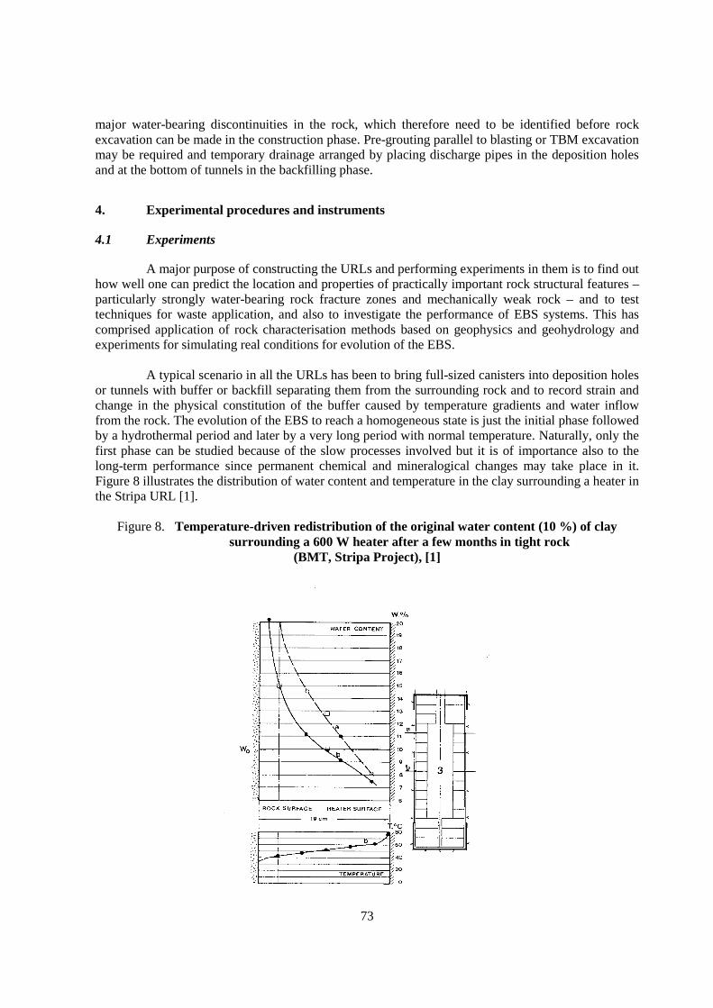
73
major water-bearing discontinuities in the rock, which therefore need to be identified before rockexcavation can be made in the construction phase. Pre-grouting parallel to blasting or TBM excavationmay be required and temporary drainage arranged by placing discharge pipes in the deposition holesand at the bottom of tunnels in the backfilling phase.
4. Experimental procedures and instruments
4.1 Experiments
A major purpose of constructing the URLs and performing experiments in them is to find outhow well one can predict the location and properties of practically important rock structural features –particularly strongly water-bearing rock fracture zones and mechanically weak rock – and to testtechniques for waste application, and also to investigate the performance of EBS systems. This hascomprised application of rock characterisation methods based on geophysics and geohydrology andexperiments for simulating real conditions for evolution of the EBS.
A typical scenario in all the URLs has been to bring full-sized canisters into deposition holesor tunnels with buffer or backfill separating them from the surrounding rock and to record strain andchange in the physical constitution of the buffer caused by temperature gradients and water inflowfrom the rock. The evolution of the EBS to reach a homogeneous state is just the initial phase followedby a hydrothermal period and later by a very long period with normal temperature. Naturally, only thefirst phase can be studied because of the slow processes involved but it is of importance also to thelong-term performance since permanent chemical and mineralogical changes may take place in it.Figure 8 illustrates the distribution of water content and temperature in the clay surrounding a heater inthe Stripa URL [1].
Figure 8. Temperature-driven redistribution of the original water content (10 %) of claysurrounding a 600 W heater after a few months in tight rock
(BMT, Stripa Project), [1]
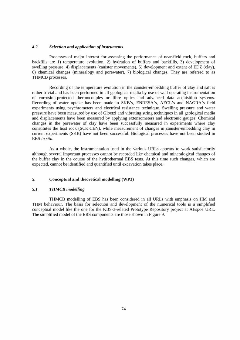
74
4.2 Selection and application of instruments
Processes of major interest for assessing the performance of near-field rock, buffers andbackfills are 1) temperature evolution, 2) hydration of buffers and backfills, 3) development ofswelling pressure, 4) displacements (canister movements), 5) development and extent of EDZ (clay),6) chemical changes (mineralogy and porewater), 7) biological changes. They are referred to asTHMCB processes.
Recording of the temperature evolution in the canister-embedding buffer of clay and salt israther trivial and has been performed in all geological media by use of well operating instrumentationof corrosion-protected thermocouples or fibre optics and advanced data acquisition systems.Recording of water uptake has been made in SKB’s, ENRESA’s, AECL’s and NAGRA’s fieldexperiments using psychrometers and electrical resistance technique. Swelling pressure and waterpressure have been measured by use of Gloetzl and vibrating string techniques in all geological mediaand displacements have been measured by applying extensometers and electronic gauges. Chemicalchanges in the porewater of clay have been successfully measured in experiments where clayconstitutes the host rock (SCK·CEN), while measurement of changes in canister-embedding clay incurrent experiments (SKB) have not been successful. Biological processes have not been studied inEBS in situ.
As a whole, the instrumentation used in the various URLs appears to work satisfactorilyalthough several important processes cannot be recorded like chemical and mineralogical changes ofthe buffer clay in the course of the hydrothermal EBS tests. At this time such changes, which areexpected, cannot be identified and quantified until excavation takes place.
5. Conceptual and theoretical modelling (WP3)
5.1 THMCB modelling
THMCB modelling of EBS has been considered in all URLs with emphasis on HM andTHM behaviour. The basis for selection and development of the numerical tools is a simplifiedconceptual model like the one for the KBS-3-related Prototype Repository project at AEspoe URL.The simplified model of the EBS components are those shown in Figure 9.
75
Figure 9. Interacting EBS components of a KBS-3 deposition hole
The evolution of the KBS-3 buffer and in principle all clay buffers in the clay and crystallinerock concepts involves:
• Redistribution of initial porewater generated by the thermal gradient across the buffer.
• Homogenisation and subsequent consolidation of the pellet fill under the swellingpressure exerted by the hydrating and expanding dense blocks.
• Uptake of water from the rock and backfill leading to hydration of the buffer.
• Expansion of the uppermost part of the buffer which displaces the overlying backfill.
• Consolidation and shearing of the buffer caused by the canister load.
• Alteration of the porewater chemistry and associated changes in buffer properties.
• Dissolution and alteration of minerals and precipitation of chemical compounds.
In the first phase the heat conductivity of the inner, drying part of the buffer decreases whilethe wetting of outer parts make them more heat-conductive. This causes a steep temperature gradientthat has chemical effect since silicate minerals in the buffer close to the heater will give off silica thatmigrates towards the rock and precipitates in the outer part of the buffer. The silicification causessome cementation and brittleness of the clay. Desiccation and vapour attack will cause similar effectsclose to the canisters. The chemical processes involved in the EBS evolution are not yet fullyunderstood and represent the third major safety-related issue evolving in the project.

76
Development of theoretical models for the evolution of clay-based EBS is focused on theinitial phase of maturation, i.e. the development of temperature and, coupled to it, redistribution of theinitial porewater content in the buffer and backfill, as well as on uptake of water from the rock. Forthis purpose several theoretical approaches have been made, like the five models that are being appliedin SKB’s Prototype Repository project at AEspoe URL for crystalline rock [5]. A major problem forthe modelers is to define the hydraulic boundaries of the buffer clay: the rock around the depositionholes gives off water through discrete fractures with a largely unknown hydraulic transport capacity,the matter being complicated by the incompletely known conductivity of the shallow boring-disturbedzone (EDZ). Figure 10, which shows the water saturation rate according to a model worked out by theGerman BGR organisation, demonstrates the impact of water pressure in the near-field rock.
Figure 10. Water saturation versus time for the case of continuously pressurised EDZ in KBS-3deposition hole by 1 MPa, and the case with virtually no pressure and water
uptake through 2 water-bearing fractures(Calculation by Lutz Liedtke, BGR), [6]
The difficulty in taking the rock constitution into consideration when predicting thesaturation rate of the buffer clay is illustrated by Figure 11 which shows the porewater pressuresituation after 4 years in a calculation for the KBS-3 concept using the ABAQUS code [7]. Oneconcludes that very significant suction still persists in the rock and buffer if water is assumed to enterthrough fracture-free rock matrix and even where there is just one sub-horizontal water-bearingfracture. The problem of correct assessment of the role of the EDZ is definitely a key question forcrystalline rock and clay shale.

77
Figure 11. Porewater pressure (kPa) in the rock after 4 years. Without fracture (left) and withfracture in the right picture [7]. Very significant suction persists in both cases
5.2 Creep modelling of rock (TM)
While the geometrical boundaries of deposition holes and tunnels can be taken as fixed incrystalline rock they undergo transient movement in clay and salt. The process is termed creep and hasthe nature of stochastic heat-assisted slip across energy barriers where the mechanical stresses aresufficiently high – usually more than 1/3 of the shear strength determined by conventional quicktesting. This matter has been thoroughly investigated for the salt URLs WIPP and ASSE, which hasled to empirically derived models for predicting long-term creep in salt. Purely thermodynamicalmodels can not be used for any host rock since there is a scale-dependence: larger volumes mean thatlarger discontinuities with different stress/strain behaviour become involved. Also, there is a criticalstrain, meaning that the continuity of the rock mass is lost when the strain is sufficiently large: blockswill not be in full contact and may fall into tunnels and holes. Furthermore, bulk creep is affected bylocal discontinuities like clay seams and variation in salt composition (i.a. halite/sylvite).
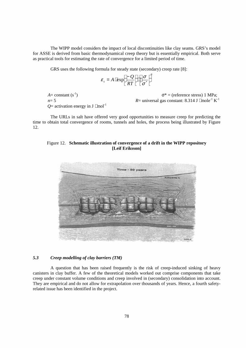
78
The WIPP model considers the impact of local discontinuities like clay seams. GRS’s modelfor ASSE is derived from basic thermodynamical creep theory but is essentially empirical. Both serveas practical tools for estimating the rate of convergence for a limited period of time.
GRS uses the following formula for steady state (secondary) creep rate [8]:n
s RT
QA
⋅
−⋅=
*exp
σσε
A= constant (s-1) σ* = (reference stress) 1 MPa;n= 5 R= universal gas constant: 8.314 J ⋅ mole-1 K-1
Q= activation energy in J ⋅ mol-1
The URLs in salt have offered very good opportunities to measure creep for predicting thetime to obtain total convergence of rooms, tunnels and holes, the process being illustrated by Figure12.
Figure 12. Schematic illustration of convergence of a drift in the WIPP repository[Leif Eriksson]
5.3 Creep modelling of clay barriers (TM)
A question that has been raised frequently is the risk of creep-induced sinking of heavycanisters in clay buffer. A few of the theoretical models worked out comprise components that takecreep under constant volume conditions and creep involved in (secondary) consolidation into account.They are empirical and do not allow for extrapolation over thousands of years. Hence, a fourth safety-related issue has been identified in the project.
79
5.4 Theoretical modeling, TCB
Conceptual models for chemical processes in buffer clay have been worked out for therespective repository concepts and transformed to simple theoretical form and included in some of thetheoretical EBS models. However, the understanding of the mechanisms leading to changes in thepore-water chemistry of buffer clay, including dissolution and precipitation phenomena, is far fromcomplete. A higher priority should consequently be put on increased understanding of the chemistryfor extrapolation of the chemical evolution in the EBS over long periods than on refinement of THMmodels to precisely predict the development of swelling pressures or creep etc in the relatively shortwater saturation period.
The possibility of practically important microbial activities in the EBS is realised by allinvestigators and conceptual models for their performance and impact on canisters have been workedout. However, detailed knowledge of the environmental conditions for survival and multiplication isstill not complete and no theoretical models appear to be at hand for predicting microbial activities inthe EBS. This is the fifth safety-related issue that has been identified
6. Conclusions
• There are obvious similarities in design philosophy among the repository concepts, and the testingprograms are similar. The instrumentation is similar as well although more effort is made todetermine creep in the URLs in salt and clay than in crystalline rock.
• Identification, characterisation and sealing – where appropriate – of EDZ is a major task thatrequires further investigations. The EDZ is most important in the hydration phase of buffers andbackfills but might be a major transport path for radionuclides escaping the canisters.
• Location and construction of plugs for temporary or permanent sealing performance in repositoriesis matter that needs further consideration, both with respect to their impact on the large-scalegroundwater flow and for cutting of EDZ.
• Long-term creep in salt and clay host media as well as in the buffer or backfill in any host mediumrequires more investigation for making safe predictions with respect to the location of canistersand compaction of backfill in a very long time perspective.
• The understanding of mechanisms leading to changes in the porewater chemistry of buffer clays,thereby affecting their physical properties in both short- and long-term perspectives, needs muchmore research. The reason is that possible changes in mineral composition and cementation canhave a very significant effect on the isolating capacity of the EBS.
• Microbiology needs to be considered and its safety implications in each host medium identified.
References
1. Pusch R, 1994. Waste Disposal in Rock – Developments in Geotechnical Engineering, 76.Elsevier Publ. Co. ISBN0-444-89449-7.
2. Rhen I, Forsmark T, Torin L, 2001. Prototype Repository. Hydrological, hydrochemical andtemperature measurements in boreholes during the operation phase of the Prototype Repository.Tunnel Section I. Int. Progr. Report IPR-01-32. SKB, Stockholm.

80
3. Munier R et al., 1999. Projekt JADE. Geovetenskapliga studier. Bergmekanisk inverkan påvattenomsättning i närfältet. SKB R-01-32. SKB, Stockholm. (Swedish text).
4. Popov V, 2002. Prediction of groundwater flow in rock with disposal of chemical waste inabandoned mines. Wessex Institute of Technology. LowRiskDT EC-supported project. Mid-term report.
5. Pusch R, 2001. Selection of THMCB models. AEspoe Hard Rock Laboratory. Int. ProgressReport IPR-01-66.
6. Liedtke L, 2002. Rate of saturation of buffer clay. EC-supported Prototype Repository Project.Mid-term report.
7. Börgesson L, Hernelind J, 1999. Coupled thermo-hydro-mechanical calculations of the watersaturation phase of a KBS-3 deposition hole. SKB Technical Report TR-99-41. SKBStockholm.
8. Rothfuchs T et al. Mechanical properties of rock salt. Country Annex to CROP WP3 report.(Internal report, unpublished.)
81
THE ROLE OF THE EBS IN DEMONSTRATING POST-CLOSURE SAFETY OF THEPROPOSED YUCCA MOUNTAIN REPOSITORY
Robert J. MacKinnonYucca Mountain Site Characterization Office
Sandia National Laboratories, USA
1. Introduction
On July 23, 2002, after more than 20 years of in-depth scientific and engineering studies, theYucca Mountain (YM) site in Nevada was legally designated by the President of the US as a site for aproposed nuclear waste repository. The US Department of Energy (DOE) may now seek a licensefrom the US Nuclear Regulatory Commission (NRC) to begin constructing a repository for geologicdisposal of spent nuclear fuel and high-level radioactive waste. DOE plans to submit a licenseapplication to NRC in 2004. If NRC grants a license, construction will begin in 2008 and the firstwaste will be received in 2010.
A unique feature of the Yucca Mountain site is its 500 to 800-meter-thick unsaturated zone(UZ). The emplacement drifts and engineered barrier system (EBS) for the potential repository will belocated in the UZ, about halfway between the ground surface and the water table in a host rock unitconsisting of volcanic tuff. The principal function of the EBS, using a design to complement thegeologic system, is to help prevent water from contacting the nuclear waste. The components of theEBS include the ground support (steel sets with welded wire and rock bolts), a drip shield over thewaste package, a two-layer waste package, a waste package emplacement pallet, and an invert(crushed tuff) at the base of the emplacement drift. The current repository design has an averagethermal load at time of waste emplacement of approximately 1.4 kW/m with 50 years of ventilationduring the pre-closure period.
The regulatory basis for the YM post-closure safety case, NRC regulation 10 CFR Part63[1], was finalised in 2001. This regulation establishes the licensing requirements for disposal ofnuclear fuel and high-level radioactive wastes in the proposed geologic repository at Yucca Mountain.The DOE’s approach to demonstrating compliance with these requirements relies on multipleindependent lines of evidence. These lines of evidence include 1) a repository design that providesdefense in depth, 2) a performance assessment of the proposed repository, 3) a laboratory and fieldtesting program, 4) natural and man-made analogues, and long-term management and monitoring.
This paper summarises the DOE’s approach to demonstrating compliance with NRClicensing requirements, and in particular focuses on the role of the EBS in this approach. The majorityof material presented here is summarised from the Yucca Mountain Science and Engineering Report[2]. The outline of the paper is as follows. The next section provides an overview of the location anddesign of the proposed repository. A section that outlines the DOE’s approach to the post-closure
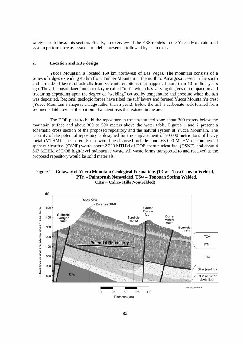
82
safety case follows this section. Finally, an overview of the EBS models in the Yucca Mountain totalsystem performance assessment model is presented followed by a summary.
2. Location and EBS design
Yucca Mountain is located 160 km northwest of Las Vegas. The mountain consists of aseries of ridges extending 40 km from Timber Mountain in the north to Amargosa Desert in the southand is made of layers of ashfalls from volcanic eruptions that happened more than 10 million yearsago. The ash consolidated into a rock type called “tuff,” which has varying degrees of compaction andfracturing depending upon the degree of “welding” caused by temperature and pressure when the ashwas deposited. Regional geologic forces have tilted the tuff layers and formed Yucca Mountain’s crest(Yucca Mountain’s shape is a ridge rather than a peak). Below the tuff is carbonate rock formed fromsediments laid down at the bottom of ancient seas that existed in the area.
The DOE plans to build the repository in the unsaturated zone about 300 meters below themountain surface and about 300 to 500 meters above the water table. Figures 1 and 2 present aschematic cross section of the proposed repository and the natural system at Yucca Mountain. Thecapacity of the potential repository is designed for the emplacement of 70 000 metric tons of heavymetal (MTHM). The materials that would be disposed include about 63 000 MTHM of commercialspent nuclear fuel (CSNF) waste, about 2 333 MTHM of DOE spent nuclear fuel (DSNF), and about 4667 MTHM of DOE high-level radioactive waste. All waste forms transported to and received at theproposed repository would be solid materials.
Figure 1. Cutaway of Yucca Mountain Geological Formations (TCw – Tiva Canyon Welded,PTn – Paintbrush Nonwelded, TSw – Topopah Spring Welded,
CHn – Calico Hills Nonwelded)

83
Figure 2. Natural System of Yucca Mountain (TCw – Tiva Canyon Welded, PTn –Paintbrush Nonwelded, TSw – Topopah Spring Welded, CHn – Calico Hills
Nonwelded, Cfu–Crater Flat Undifferentiated, GDF – Ghost Dance Fault, SCF –Solitario Canyon)
The natural system and the EBS both contribute to repository performance. The naturalsystem contributes by 1) limiting the amount of water entering the drifts and 2) limiting the transportof radionuclides through the system. The EBS is designed to complement the natural system andcontributes by 1) using long-lived dripshields and waste packages to keep water away from waste, and2) limiting release of radionuclides through retention, retardation, and diffusion barriers.
Preliminary engineering specifications have been developed for the EBS. Thesespecifications have been developed based on an iterative process that integrates design, site-specificdata, models, and analyses. These analyses include total-system performance assessments of thepotential repository in 1991[3], 1993[4], 1995[5], 1998[6], 2000[7], and 2001[8,9]. The iterativeprocess has focused on improving the understanding of the contribution of design features toperformance of the repository over a range of thermal operating modes. If a design attribute is shownto have a significant impact on performance, then the attribute undergoes further evaluation to fullydevelop the positive contribution or minimise the negative contribution to performance. This flexibledesign will continue to evolve for license application (LA). Considerations of safety margin, defensein depth, insights from analogues, and expert judgements also help identify importance of repositorycomponents to performance.
84
Key design assumptions and requirements include:
• Design should support staged repository development
• Receive waste no later than 2010
• Design must meet 10 CFR Part 63 performance requirements for postclosure safety
• Flexible post-closure thermal operating mode
• Defense in depth
Staged repository development is a process that will permit decisions concerning therepository design, development, and operation to be made in a step-wise manner. That is, at each stepin the process a decision whether to proceed would be made based on the regulatory and licensingrequirements, the funding profile, and operating experience. The next stage would proceed informedby the experience of the previous stage.
The postclosure performance objectives for the potential geologic repository requires theDOE to include a system of multiple barriers, comply with the individual annual dose limit andgroundwater protection standards, conduct a performance assessment, and assess the consequences ofa specified human intrusion event. The objective incorporates the standards set by the EPA in rule 40CFR 197[10] and adopted by the NRC in the final implementing rule, 10 CFR 63[1].
A flexible post-closure thermal operating mode will permit repository operation over a rangeof thermal environments. This range is being examined to further identify the potential performancebenefits of different environmental conditions (lower and higher temperatures and associated relativehumidity conditions) in the emplacement drifts. A defense in depth approach (or reliance on multiplesystem attributes) is an important element of the YMP safety case in that it provides a method ofensuring overall performance if one or more components of the repository system fail to perform asexpected. Having safety components that do not share common failure modes provides defense indepth.
A schematic representation of the EBS is presented in Figure 3. In general, the majorcomponents of the base case design will include an areal mass load (approximately 60 metric tons ofuranium [MTU]/acre), with closely-spaced waste packages. The EBS will include the followingcomponents:

85
Figure 3. Schematic of Engineered Barrier System Design Evaluated in the Total SystemPerformance Assessment – Site Recommendation [7]
Drift Support (steel sets with welded wire and rock bolts):
A drift support system has been included in the design, primarily in support of preclosuresafety.
Drip Shield (titanium alloy):
The drip shield is 1.5-cm thick and continuous in the drift over the waste packages. It servesto reduce the effect of rock fall and dripping on the waste package.
86
Waste Package:
Waste packages consist of an outer layer and an inner layer. The outer layer is a nickel-basedalloy that is very resistant to aqueous corrosion and nearly totally resistant to humid aircorrosion. The current reference corrosion-resistant material is 2 cm of Alloy-22. The innerlayer is 5-cm thick stainless steel and serves three functions. First, it provides structuralstrength to resist rock falls, to support the internal components, to be supported by theemplacement pallet and to be handled. Second, the inner layer provides radiation shielding toreduce exterior surface contact dose rate. Third, the inner layer acts as a limited containmentbarrier for the radioactive waste inside the waste package. The current waste packagereference design is based on a 21 pressurised water reactor spent nuclear fuel assembly wastepackage. Roughly the same size waste package can also accommodate 44 of the smallerboiling water reactor (BWR) SNF assemblies, five defense high level waste glass “logs”surrounding a central canister of DOE-owned SNF, or a naval spent nuclear fuel canister.
Alloy 22 Emplacement Pallet:
The emplacement pallets provide support for the waste packages during the preclosureperiod. The pallets will be emplaced along with the waste packages. Each waste package willrest on one pallet.
Invert:
The invert is designed to provide support for the waste package emplacement pallets and thedrip shields. It will be composed of granular ballast (e.g., crushed, welded tuff), betweensteel beams that support the rails used during the pre-closure period for waste emplacementand performance confirmation equipment.
3. Approach to the post-closure safety case
The DOE’s approach to developing confidence in the safety of geologic disposal, known asthe post-closure safety case, relies on multiple, independent lines of evidence. These lines of evidenceare designed to collectively provide confidence and assurance that the repository will meet applicableregulatory performance standards after it is permanently closed.
The first element of the post-closure safety case is the quantitative analysis of repositoryperformance, based on a comprehensive testing program that has evolved to address identifieduncertainties and an EBS designed to complement the natural setting of the site. EPA and NRCregulations specify that DOE will perform a total system performance assessment (TSPA) to analyseand demonstrate that a repository can safely isolate high-level radioactive waste and meet theregulatory post-closure performance objectives.
To give the reader some understanding of the repository performance objectives anabbreviated summary of NRC performance objectives for the repository is provided below [1]. Notethat all objectives are relevant to the EBS. References to the EBS are highlighted in bold italic font.
63.113 Performance Objectives for the Geologic Repository After Permanent Closure
63.113(a) The geologic repository must include multiple barriers, consisting of both naturalbarriers and an engineered barrier system.

87
63.113(b) The engineered barrier system must be designed so that, working in combinationwith natural barriers, radiological exposures to the reasonably maximally exposed individual arewithin the limits specified at § 63.311. Compliance with this paragraph must be demonstrated througha performance assessment.
(c) The engineered barrier system must be designed so that, working in combination withnatural barriers, releases of radionuclides into the accessible environment are within the limitsspecified at § 63.331. Compliance with this paragraph must be demonstrated through a performanceassessment.
(d) The ability of the geologic repository to limit radiological exposures to the reasonablymaximally exposed individual, in the event of human intrusion into the engineered barrier system,must be demonstrated through an analysis that meets the requirements at §§ 63.321 and 63.322.
Because DOE recognises that uncertainty about future performance of the repository cannotbe completely quantified, the safety case includes the following additional lines of evidence:
• Studies of natural and man-made analogues to the repository or to processes that mayaffect repository performance. These studies can further the understanding of naturalprocesses related to repository performance that operate over long time frames or largespatial distances that cannot be easily tested.
• Laboratory- and field-testing program to improve understanding of coupled processesand uncertainties.
• Selection and design of a repository system that provides defense in depth and a marginof safety. The EBS is comprised of multiple barriers, so that safety of the repositorydoes not depend on only one or two barriers.
• Long-term management and performance confirmation programme to ensure integrityand security of the repository and to ensure that the scientific and engineering bases forthe safety case are well founded.
The approach outlined above is similar to approaches recommended by many national andinternational organisations that have investigated the technical and social issues related to nuclearwaste disposal.
4. Total system performance assessment and EBS models
The Yucca Mountain repository system is a combination of integrated processes. The systemcan be conceptualised and modelled as a collection of component models that are coupled. Thissection briefly summarises the key aspects of the individual component models.
Eight principal model components in the TSPA are combined to evaluate the proposedrepository system performance for nominal and disruptive event scenario classes [7,12]. The modelcomponents, listed in the general order information is passed from model to model, include:
1. Unsaturated zone flow2. Engineered barrier system environment3. Waste package and drip shield degradation4. Waste form degradation and mobilization5. Engineered barrier system flow and transport
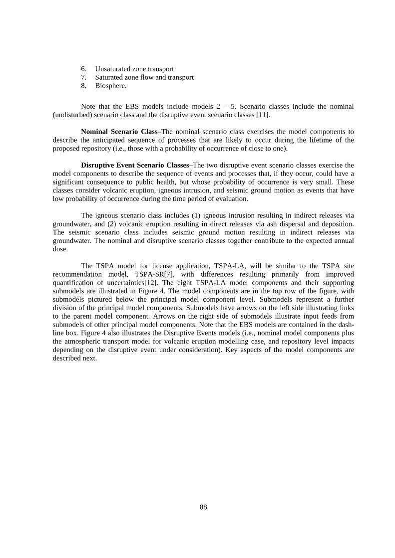
88
6. Unsaturated zone transport7. Saturated zone flow and transport8. Biosphere.
Note that the EBS models include models 2 – 5. Scenario classes include the nominal(undisturbed) scenario class and the disruptive event scenario classes [11].
Nominal Scenario Class–The nominal scenario class exercises the model components todescribe the anticipated sequence of processes that are likely to occur during the lifetime of theproposed repository (i.e., those with a probability of occurrence of close to one).
Disruptive Event Scenario Classes–The two disruptive event scenario classes exercise themodel components to describe the sequence of events and processes that, if they occur, could have asignificant consequence to public health, but whose probability of occurrence is very small. Theseclasses consider volcanic eruption, igneous intrusion, and seismic ground motion as events that havelow probability of occurrence during the time period of evaluation.
The igneous scenario class includes (1) igneous intrusion resulting in indirect releases viagroundwater, and (2) volcanic eruption resulting in direct releases via ash dispersal and deposition.The seismic scenario class includes seismic ground motion resulting in indirect releases viagroundwater. The nominal and disruptive scenario classes together contribute to the expected annualdose.
The TSPA model for license application, TSPA-LA, will be similar to the TSPA siterecommendation model, TSPA-SR[7], with differences resulting primarily from improvedquantification of uncertainties[12]. The eight TSPA-LA model components and their supportingsubmodels are illustrated in Figure 4. The model components are in the top row of the figure, withsubmodels pictured below the principal model component level. Submodels represent a furtherdivision of the principal model components. Submodels have arrows on the left side illustrating linksto the parent model component. Arrows on the right side of submodels illustrate input feeds fromsubmodels of other principal model components. Note that the EBS models are contained in the dash-line box. Figure 4 also illustrates the Disruptive Events models (i.e., nominal model components plusthe atmospheric transport model for volcanic eruption modelling case, and repository level impactsdepending on the disruptive event under consideration). Key aspects of the model components aredescribed next.
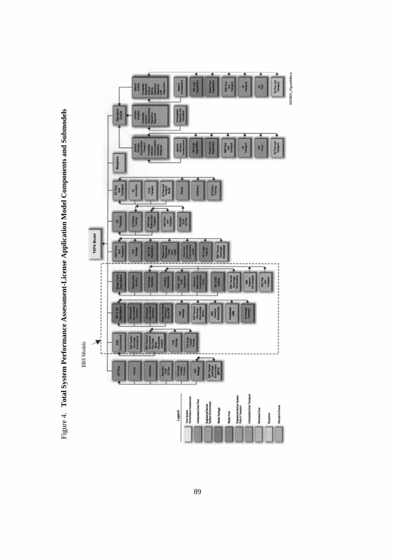
Figu
re 4
. T
otal
Sys
tem
Per
form
ance
Ass
essm
ent-
Lic
ense
App
licat
ion
Mod
el C
ompo
nent
s an
d Su
bmod
els
89
90
The natural system is modelled by the unsaturated zone (UZ)[13], saturated zone (SZ)[14],and Biosphere models [15]. The UZ flow model defines the temporal and spatial distribution of waterflow through the unsaturated tuffs above and below the proposed repository horizon and the temporaland spatial distribution of water seeps into the waste emplacement drifts. The UZ Transport and SZFlow and Transport models calculate the migration of radionuclides from the EBS through theunsaturated zone and saturated zones to the biosphere. The Biosphere model is used to predicttransport of radionuclides through a range of possible biological pathways to the point where they areingested or inhaled by humans.
The EBS models (EBS Environments [16,17], Waste Package and Drip ShieldDegradation[18], Waste Form Degradation and Mobilization[19], and EBS Flow and Transport[16])are used to evaluate the release of radionuclides from the EBS. The design is used as a basis for theevaluation, with key processes influenced by the design. These processes include thermal hydrology,chemical processes such as dissolution and precipitation, drip shield and waste package degradation,cladding degradation, waste form degradation, colloid formation and stability, and radionuclidetransport within waste packages and through the EBS. The EBS models evaluate the followingsequence of processes:
• The temporal and spatial evolution of thermal-hydrologic and chemical environments onthe engineered barriers (notably the drip shields and waste packages)
• Degradation of the engineered barriers within the range of possible thermal-hydrologicand chemical environments
• The thermal-hydrologic and chemical environments within the waste packages once theprimary containment has been degraded to the point that corrosion breaches penetratethe waste package
• The alteration rate of the waste form within the waste package, whether it is commercialspent nuclear fuel, DOE spent nuclear fuel (including naval spent nuclear fuel) or high-level radioactive waste, including immobilised plutonium waste forms
• The release of dissolved or colloidal radionuclides through the degraded engineeredbarriers to the host rock
5. Summary
The DOE’s approach to developing the post-closure safety case relies on multiple,independent lines of evidence. These lines of evidence include total-system performance assessment,studies of man-made and natural analogues, selection and design of a repository that provides defensein depth and a margin of safety, and long-term management and monitoring. The regulatoryrequirements for the high-level radioactive waste program are based on quantitative assessments forthe system’s performance. For Yucca Mountain, performance assessment provides not only a meansfor estimating relative performance, but also a framework for organising and describing the site anddesigning the EBS.
The EBS is designed to complement the natural barriers in isolating waste from theenvironment. The EBS would contribute to waste isolation by 1) using long-lived dripshields andwaste packages to keep water away from waste, and 2) limiting release of radionuclides throughretention, retardation, and diffusion barriers.
91
The DOE has adopted an approach to the post-closure safety case that relies on multiple,independent lines of evidence to build confidence in the analyses of repository performance andassurance that the repository will meet applicable post-closure performance standards. The degree ofsafety margin (the difference between expected performance and the regulatory limit) and theindependence of measures that provide defense in depth are continuing to being assessed, bothqualitatively and quantitatively. The DOE is continuing to study analogues that may provide importantadditional information about the reliability of the performance assessment models. Performanceconfirmation activities will monitor the behaviour of the repository and enable future managers tocontinuously assess the technical bases for decisions about the repository. Collectively, these multiplelines of evidence are known as the post-closure safety case. Elements of the safety case include:
• Quantitative assessments of long-term performance. For Yucca Mountain, performanceassessment provides not only a means for estimating relative performance, but also aframework for organising and describing the site and designing the EBS.
• Design of a repository that provides defense in depth – a system of multiple,independent, and redundant barriers designed to ensure that failure of one barrier doesnot result in failure of the entire system. The system would also provide a margin ofsafety against radionuclide release and a margin of safety compared to health and safetyrequirements.
• Qualitative insights gained from the study of natural and man-made analogues to therepository or to processes that may affect repository performance.
• Laboratory- and field-testing program to improve understanding of coupled processesand uncertainties.
• Long-term management to ensure integrity and security of the repository, and long-termmonitoring to monitor the behaviour of the repository and enable sound and scientificand engineering bases for a later repository closure decision.
References
1. 10 CFR Part 63, Disposal of High-Level Radioactive Wastes in a Proposed Geologic Repositoryat Yucca Mountain, Nevada. Final rule. Readily available.
2. 2002. Yucca Mountain Science and Engineering Report. DOE/RW-0539, Rev. 1. Washington,D.C.: U.S. Department of Energy, Office of Civilian Radioactive Waste Management. ACC:MOL.20020404.0042.
3. 1992. Barnard, R.W.; Wilson, M.L.; Dockery, H.A.; Gauthier, J.H.; Kaplan, P.G.; Eaton, R.R.;Bingham, F.W.; and Robey, T.H. TSPA 1991: An Initial Total-System Performance Assessmentfor Yucca Mountain. SAND91-2795. Albuquerque, New Mexico: Sandia National Laboratories.ACC: NNA.19920630.0033.
4. 1994. Total System Performance Assessment – 1993: An Evaluation of the Potential YuccaMountain Repository. B00000000-01717-2200-00099 REV 01. Las Vegas, Nevada: CRWMSM&O. ACC: NNA.19940406.0158.
5. 1995. Total System Performance Assessment – 1995: An Evaluation of the Potential YuccaMountain Repository. B00000000-01717-2200-00136 REV 01. Las Vegas, Nevada: CRWMSM&O. ACC: MOL.19960724.0188.

92
6. 1998. Total System Performance Assessment – Viability Assessment Base Case. B00000000-01717-0210-00011 REV 01. Las Vegas, Nevada: CRWMS M&O. ACC: MOL.19981202.0279.
7. 2000. Total System Performance Assessment for the Site Recommendation. TDR-WIS-PA-000001 REV 00 ICN 01. Las Vegas, Nevada: CRWMS M&O. ACC: MOL.20001220.0045.
8. 2001. FY 01 Supplemental Science and Performance Analyses, Volume 1: Scientific Bases andAnalyses. TDR-MGR-MD-000007 REV 00 ICN 01. Las Vegas, Nevada: Bechtel SAICCompany. ACC: MOL.20010801.0404; MOL.20010712.0062; MOL.20010815.0001
9. 2001. FY01 Supplemental Science and Performance Analyses, Volume 2: PerformanceAnalyses. TDR-MGR-PA-000001 REV 00. Las Vegas, Nevada: Bechtel SAIC Company. ACC:MOL.20010724.0110.
10. 40 CFR Part 197, Public Health and Environmental Radiation Protection Standards for YuccaMountain, NV; Final Rule. Readily available.
11. 2000. Disruptive Events Process Model Report. TDR-NBS-MD-000002 REV 00. Las Vegas,Nevada: CRWMS M&O. ACC: MOL.20000504.0295.
12. 2002. Total System Performance Assessment-License Application Methods and Approach.TDR-WIS-PA-000006 REV 00. Las Vegas, Nevada: CRWMS M&O.
13. 2000. Unsaturated Zone Flow and Transport Model Process Model Report. TDR-NBS-HS-000002 REV 00 ICN 02. Las Vegas, Nevada: CRWMS M&O. ACC: MOL.20000831.0280.
14. 2000. Saturated Zone Flow and Transport Process Model Report. TDR-NBS-HS-000001 REV00. Las Vegas, Nevada: CRWMS M&O. ACC: MOL.20000502.0238.
15. 2000. Biosphere Process Model Report. TDR-MGR-MD-000002 REV 00 ICN 01. Las Vegas,Nevada: CRWMS M&O. ACC: MOL.20000620.0341.
16. 2000. Engineered Barrier System Degradation, Flow, and Transport Process Model Report.TDR-EBS-MD-000006 REV 00. Las Vegas, Nevada: CRWMS M&O. ACC:MOL.20000324.0558.
17. 2000. Near Field Environment Process Model Report. TDR-NBS-MD-000001 REV 00. LasVegas, Nevada: CRWMS M&O. ACC: MOL.20000421.0034.
18. 2000. Waste Package Degradation Process Model Report. TDR-WIS-MD-000002 REV 00. LasVegas, Nevada: CRWMS M&O. ACC: MOL.20000328.0322.
19. 2000. Waste Form Degradation Process Model Report. TDR-WIS- MD-000001 REV 00. LasVegas, Nevada: CRWMS M&O. ACC: MOL.20000403.0495.
Sandia is a multiprogramme laboratory operated by Sandia Corporation, a Lockheed MartinCompany for the United States Department of Energy’s National Nuclear SecurityAdministration under contract DE-AC04-94AL85000.

93
ENGINEERED BARRIERS SYSTEM MODELLINGAND PERFORMANCE ASSESSMENT IN SAFIR 2
Xavier Sillen and Jan Marivoet(SCK•CEN, Belgium)
Jean-Paul Boyazis, Philippe Lalieux, Peter De Preter and Johan Bel(ONDRAF/NIRAS, Belgium)
Abstract
In 2001, ONDRAF/NIRAS completed a second Safety Assessment and Interim Report,SAFIR 2, on the Belgian research and development programme on geological disposal of radioactivewastes. This report presents the state of the art in Belgium about deep disposal of high and medium-level wastes in a clay formation. In SAFIR 2, the focus was very much on the capacity of the BoomClay to fulfil its role as main barrier. Indeed, in many evolution scenarios it has been shown that theclay host formation plays the dominant role in performance assessment (PA) calculations.Nevertheless, the basic assumptions on which these PA calculations rest often depend much onprocesses which occur inside or in the vicinity of the engineered barriers system (EBS). In this respect,detailed EBS modelling appears complementary to PA calculations. To ensure the sound transfer ofEBS behaviour understanding, a tight collaboration between experimentalists, modellers and PAspecialists is required.
1. Introduction – the SAFIR 2 report
In 2001, ONDRAF/NIRAS completed a second Safety Assessment and Interim Report,SAFIR 2, on the Belgian research and development programme for geological disposal of radioactivewastes. The SAFIR 2 report is meant to inform the Belgian authorities of the technical and scientificaspects of high-level waste (HLW) and medium-level waste (MLW) disposal in poorly induratedclays. The SAFIR 2 repository concept is shown in Figure 1.
Although only the Boom Clay formation has been studied for SAFIR 2, no specific site is beingselected. The report was by no means written as a safety case pending a licence application. On thecontrary, this report presents an interim review of the state of the art in Belgium and will be a keyreference to define –and to get approved– the next methodological research and development phase ofthe programme. SAFIR 2 covers the period 1990-2000 and its focus lies principally on the capacity ofthe Boom Clay as a geological barrier. In parallel with the research and development programme, therepository design and especially the engineered barrier system (EBS) will be revised and refined, anin-situ feasibility demonstration will be performed and all safety-relevant available data will beintegrated by 2010-2012 in a safety case.
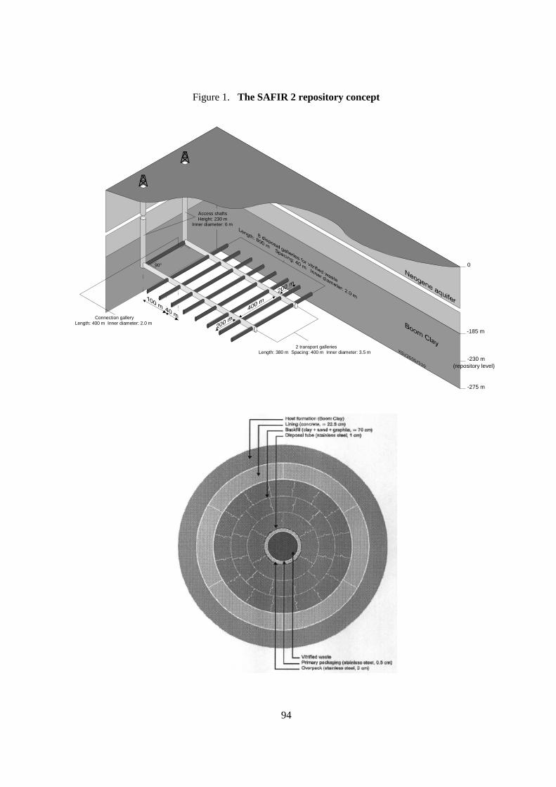
94
Figure 1. The SAFIR 2 repository concept
90°
2 transport galleriesLength: 380 m Spacing: 400 m Inner diameter: 3.5 m
Connection galleryLength: 400 m Inner diameter: 2.0 m
Access shaftsHeight: 230 m
Inner diameter: 6 m
0
-185 m
-230 m(repository level)
-275 m
95
The conclusions from SAFIR 2 increase the confidence in the capability of the Boom Clay toeffectively control the migration of radionuclides through molecular diffusion, advection beingnegligible. Favourable sorption capacities of the Boom Clay for several important nuclides was alsodemonstrated. In fact, performance assessment (PA) calculations have shown that the Boom Clay is,by far, the dominant barrier against nuclide migration in the normal evolution scenario.
2. The long-term safety functions
A safety function is defined as an action or role that the disposal system or its environmentmust perform to prevent the radionuclides present in the disposed waste posing an unacceptable hazardto humans or the environment.
There are four safety functions:
• The function of physical containment C aims to isolate the radionuclides from theirimmediate environment to prevent any significant release of radioactivity.
− The sub-function of watertightness C1 prevents water coming into contact with thewaste.
− The sub-function of limiting the water influx C2 postpones the moment when thebarriers that provide a watertightness function, and then the radionuclides, arecontacted by infiltrating water.
• The function of delaying and spreading the releases R aims to slow down the migrationof radionuclides towards the biosphere as much as possible to allow maximumradioactive decay within the disposal system.
− The sub-function of resistance to leaching R1 spreads the release of radionuclides bythe waste matrix.
− The sub-function of diffusion and retention R2 delays and spreads the release of theradionuclides.
• The function of dilution and dispersion D brings about a reduction in the concentrationof radionuclides that will eventually reach the biosphere, and so reduces their potentialimpact on humans and the environment.
• The function of limitation of access L aims to isolate the waste to minimise theprobability and consequences of human intrusion.
The first two safety functions are performed by the disposal system as a whole or by one ormore of its components. The third function is performed by the environment of the disposal system.The fourth function is performed, together, by the disposal system, its environment, and institutionalmeasures.
3. The role of EBS
In the Belgian concept (see Figure 1), the relative performance of the EBS and the BoomClay can be assessed from Table 1, which shows the fractions of the initial inventory of severalradionuclides released by various compartments of the repository system in the normal evolutionscenario. Comparing the fractions released by the bentonite buffer and the Boom Clay, it appears thatthe latter is the place where most of the safety-relevant radionuclides decay during their migration.
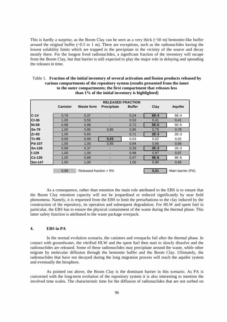
96
This is hardly a surprise, as the Boom Clay can be seen as a very thick (~50 m) bentonite-like bufferaround the original buffer (~0.5 to 1 m). There are exceptions, such as the radionuclides having thelowest solubility limits which are trapped in the precipitate in the vicinity of the source and decaymostly there. For the longest lived radionuclides, a significant fraction of the inventory will escapefrom the Boom Clay, but that barrier is still expected to play the major role in delaying and spreadingthe releases in time.
Table 1. Fraction of the initial inventory of several activation and fission products released byvarious compartments of the repository system (results presented from the inner
to the outer compartments; the first compartment that releases lessthan 1% of the initial inventory is highlighted)
Canister Waste form Precipitate Buffer Clay Aquifer
C-14 0,79 0,37 - 0,24 6E-4 5E-4Cl-36 1,00 0,55 - 0,53 0,41 0,41Ni-59 0,98 0,98 - 0,72 5E-5 5E-5Se-79 1,00 0,85 0,85 0,85 0,79 0,79Zr-93 1,00 0,83 - 0,71 2E-3 2E-3Tc-99 0,99 0,99 0,03 0,03 0,02 0,02Pd-107 1,00 1,00 0,85 0,84 0,66 0,66Sn-126 0,99 0,37 - 0,33 2E-3 2E-3I-129 1,00 1,00 - 0,98 0,97 0,97Cs-135 1,00 0,88 - 0,47 9E-6 9E-6Sm-147 1,00 1,00 - 1,00 0,95 0,95
0,99 : Released fraction > 5% 0,01 : Main barrier (PA)
RELEASED FRACTION
As a consequence, rather than retention the main role attributed to the EBS is to ensure thatthe Boom Clay retention capacity will not be jeopardised or reduced significantly by near fieldphenomena. Namely, it is requested from the EBS to limit the perturbations to the clay induced by theconstruction of the repository, its operation and subsequent degradation. For HLW and spent fuel inparticular, the EBS has to ensure the physical containment of the waste during the thermal phase. Thislatter safety function is attributed to the waste package overpack.
4. EBS in PA
In the normal evolution scenario, the canisters and overpacks fail after the thermal phase. Incontact with groundwater, the vitrified HLW and the spent fuel then start to slowly dissolve and theradionuclides are released. Some of these radionuclides may precipitate around the waste, while othermigrate by molecular diffusion through the bentonite buffer and the Boom Clay. Ultimately, theradionuclides that have not decayed during the long migration process will reach the aquifer systemand eventually the biosphere.
As pointed out above, the Boom Clay is the dominant barrier in this scenario. As PA isconcerned with the long-term evolution of the repository system it is also interesting to mention theinvolved time scales. The characteristic time for the diffusion of radionuclides that are not sorbed on
97
the Boom Clay through the host formation is about 60,000 years. As many radionuclides are sorbed,some strongly, much longer transport times are expected. In contrast, the main processes taking placein and around the EBS occur on shorter time scales. The hydraulic transient will last from a few tens toa few hundreds of years, the thermal phase will not last more than a couple of thousands of years andthe oxidising conditions around the canisters should only prevail during the first hundred of years.
Because of their limited retention role and the time scales involved, the EBS components areoften either conservatively neglected in PA or lumped into the model of radionuclide transport throughthe host formation. For example:
• the contributions of the metallic disposal tube and the concrete gallery lining to theretention of radionuclides are entirely neglected;
• the canisters and overpacks are conservatively assumed to fail instantly at the end of thethermal phase;
• the slow dissolution of the waste matrix and the subsequent release of radionuclides isexternalised as the source term of a the transport model;
• the bentonite buffer is directly included in the model of diffusive transport through theBoom Clay;
• the effective thickness of the Boom Clay is reduced to account for possibly enhancedtransport in the excavation disturbed zone and ageing EBS.
In fact, the complete EBS was represented in most PA calculations reported in SAFIR 2 by asingle mixing cell including a source term and solubility limits. For the normal evolution scenario,comparisons with higher resolution models have shown little or no difference with respect to relevantperformance or safety indicators such as fluxes into the aquifers or individual dose rates.
The behaviour of some components of the EBS is explicitly modelled, however, when theirperformance is crucial in specific altered evolution scenarios. For instance, flow and radionculidetransport inside the EBS are computed to some detail for scenarios involving advective transportthrough the repository galleries and shaft. This might occur in case of poor sealing, human intrusion orundetected water conducting feature. Then again, the Boom Clay still prevail in many of thesescenarios. For example, if the water flowing through the repository in the case of poor sealing has tocome from the host formation, the flow rate can be as small as 40 litres per year in a 200 m longgallery due to the very low permeability of the Boom Clay.
5. Does the EBS matter in the PA of repositories in clay?
In many evolution scenarios the EBS is represented in a very basic way, if at all, in PA.Nonetheless, this does not mean that engineered barriers do not play a role in the overall safety of therepository system or that a detailed analysis of the EBS evolution is not needed. Even in cases wherethe EBS behaviour is not directly modelled in PA, it nonetheless determines essential PA assumptions,for example:
• the chemical behaviour of the EBS can be of paramount importance to ensure thatcanister integrity lasts until the end of the thermal phase and to limit the subsequentdissolution rate of the waste forms;
• the mechanical performance of the EBS affects the extents of the disturbed clay zone;
98
• a low hydraulic conductivity of EBS components reduce the likeliness of significantadvective transport through the repository in case of a local failure of repository seals.
Because of this, modelling of the processes taking place in the EBS is useful for repositoriesin clay. In particular, PA specialists need to assess whether:
• a detailed process-level model justifies or not the assumptions made for a PA model(example: the corrosion of the overpack is slow enough to prevent contact betweenradionuclides and water during the thermal phase, so ’cold’ migration parameters can beused in PA);
• results of process-level models warrant an update of the values of the parameters of themodels used in PA (example: altered sorption capacity of the excavation disturbed zonedue to oxidation);
• some processes need to be directly implemented in PA models of altered evolutionscenarios (example: corrosion gas driven flow and transport).
6. Conclusions and perspectives
In SAFIR 2, the focus was very much on the capacity of the Boom Clay to fulfil its role asmain barrier. In the normal evolution as well as in some altered evolution scenarios it has been shownindeed that the clay host formation plays the dominant role in PA calculations. Nevertheless, the basicassumptions on which these PA calculations rest often depend much on processes which occur insideor in the vicinity of the EBS.
In the Belgian programme, it is acknowledged that significant uncertainties remain on thebehaviour of EBS components such as the overpack (corrosion process) and the buffer (physico-chemical evolution during the thermal and chemical transients). In fact, the post-SAFIR 2 era openswith an extensive review of EBS design alternatives, with emphasis on the choice and expectedbehaviour of materials (compatibility), proven and robust industrial solutions (feasibility) and thesimplification of underground operations during the operational phase.
Beyond feasibility, technological and economical aspects, the design of the EBS should aimat keeping the integrated PA as robust and defensible as possible. Nevertheless, detailed EBSmodelling is sometimes unavoidable to duly justify PA assumptions or to demonstrate whether (andhow) PA models need to be enhanced, particularly in connection with new or altered evolutionscenarios. To this aim, it is sometimes necessary to apply process level models that were developedon the basis of laboratory or in-situ experiments to the time frames and the spatial scales relevant toPA. This can only be achieved in a sound way through tight collaboration between experimentalists,modellers and PA specialists.
References
SAFIR 2 (2001) Safety Assessment and Feasibility Interim Report 2. ONDRAF/NIRAS, Brussels,Belgium, NIROND 2001-06 E.
99
EBS MODELLING AND PERFORMANCE ASSESSMENT FROM H12:RESULTS, CONCLUSIONS AND FUTURE PRIORITIES
Hiroyuki Umeki, Hiroyoshi Ueda and Morimasa NaitoNUMO, JAPAN
Masao ShiotsukiJNC, JAPAN
Abstract
The H12 performance assessment (PA) provided a test for the robustness of a high-levelradioactive waste (HLW) repository concept based on integrated siting and design, taking account of awide range of potentially suitable Japanese geological environments (JNC, 2000). The assessmentincluded a comprehensive evaluation of uncertainty and potentially detrimental factors, includingperturbations due to external events and processes. Despite the lack of site-specific data thatnecessitated a broadly generic analysis for this initial stage of the Japanese programme, the safety casemade is adequate for the intended objectives of the assessment: (1) analysis of sources and magnitudeof uncertainties and the conservatism necessary to mitigate such uncertainties and (2) evaluation of thereliability and effectiveness of barriers and processes contributing to radionuclide isolation within theengineered barrier system (EBS) of the near field. This paper presents the EBS modelling for the H12PA in terms of the results, conclusions and future priorities.
1. Introduction
In Japan, as outlined in the overall high-level radioactive waste (HLW) managementprogramme defined by the Japanese Atomic Energy Commission (AEC, e.g. AEC, 2000), HLW fromreprocessing of spent nuclear fuel will be immobilised in a glass matrix and stored for a period of 30to 50 years to allow cooling. It will then be disposed of in a deep geological formation. The JapanNuclear Cycle Development Institute (JNC) completed a second progress report (referred to as H12)on generic research and development for geological disposal of HLW in Japan and submitted it to theAEC in November 1999. The primary objective of H12, as specified in the guidelines published by theAdvisory Committee on Nuclear Fuel Cycle Backend Policy of the AEC (AEC, 1997), is to present anoutline of the technical reliability of geological disposal in Japan. It also provided input for the sitingand regulatory processes, which would be set in motion after the year 2000.
Taking account of the technical achievements of H12, the “Specified Radioactive WasteFinal Disposal Act” was promulgated in June 2000. Pursuant to the overall HLW managementprogramme, thereby the Nuclear Waste Management Organization of Japan (NUMO) was established
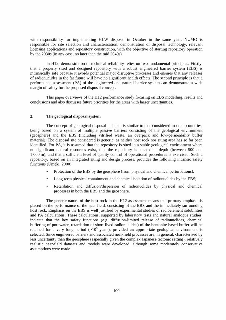
100
with responsibility for implementing HLW disposal in October in the same year. NUMO isresponsible for site selection and characterisation, demonstration of disposal technology, relevantlicensing applications and repository construction, with the objective of starting repository operationby the 2030s (in any case, no later than the mid 2040s).
In H12, demonstration of technical reliability relies on two fundamental principles. Firstly,that a properly sited and designed repository with a robust engineered barrier system (EBS) isintrinsically safe because it avoids potential major disruptive processes and ensures that any releasesof radionuclides in the far future will have no significant health effects. The second principle is that aperformance assessment (PA) of the engineered and natural barrier system can demonstrate a widemargin of safety for the proposed disposal concept.
This paper overviews of the H12 performance study focusing on EBS modelling, results andconclusions and also discusses future priorities for the areas with larger uncertainties.
2. The geological disposal system
The concept of geological disposal in Japan is similar to that considered in other countries,being based on a system of multiple passive barriers consisting of the geological environment(geosphere) and the EBS (including vitrified waste, an overpack and low-permeability buffermaterial). The disposal site considered is generic, as neither host rock nor siting area has so far beenidentified. For PA, it is assumed that the repository is sited in a stable geological environment whereno significant natural resources exist, that the repository is located at depth (between 500 and1 000 m), and that a sufficient level of quality control of operational procedures is exercised. Such arepository, based on an integrated siting and design process, provides the following intrinsic safetyfunctions (Umeki, 2000):
• Protection of the EBS by the geosphere (from physical and chemical perturbations);
• Long-term physical containment and chemical isolation of radionuclides by the EBS;
• Retardation and diffusion/dispersion of radionuclides by physical and chemicalprocesses in both the EBS and the geosphere.
The generic nature of the host rock in the H12 assessment means that primary emphasis isplaced on the performance of the near field, consisting of the EBS and the immediately surroundinghost rock. Emphasis on the EBS is well justified by experimental studies of radioelement solubilitiesand PA calculations. These calculations, supported by laboratory tests and natural analogue studies,indicate that the key safety functions (e.g. diffusion-limited release of radionuclides, chemicalbuffering of porewater, retardation of short-lived radionuclides) of the bentonite-based buffer will beretained for a very long period (>105 years), provided an appropriate geological environment isselected. Since engineered barriers and associated near-field processes are, in general, characterised byless uncertainty than the geosphere (especially given the complex Japanese tectonic setting), relativelyrealistic near-field datasets and models were developed, although some moderately conservativeassumptions were made.
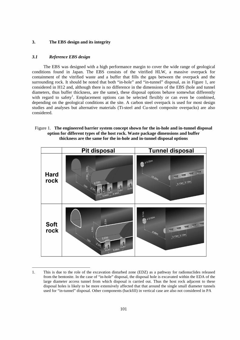
101
3. The EBS design and its integrity
3.1 Reference EBS design
The EBS was designed with a high performance margin to cover the wide range of geologicalconditions found in Japan. The EBS consists of the vitrified HLW, a massive overpack forcontainment of the vitrified waste and a buffer that fills the gaps between the overpack and thesurrounding rock. It should be noted that both “in-hole” and “in-tunnel” disposal, as in Figure 1, areconsidered in H12 and, although there is no difference in the dimensions of the EBS (hole and tunneldiameters, thus buffer thickness, are the same), these disposal options behave somewhat differentlywith regard to safety1. Emplacement options can be selected flexibly or can even be combined,depending on the geological conditions at the site. A carbon steel overpack is used for most designstudies and analyses but alternative materials (Ti-steel and Cu-steel composite overpacks) are alsoconsidered.
Figure 1. The engineered barrier system concept shown for the in-hole and in-tunnel disposaloption for different types of the host rock. Waste package dimensions and buffer
thickness are the same for the in-hole and in-tunnel disposal options
1. This is due to the role of the excavation disturbed zone (EDZ) as a pathway for radionuclides released
from the bentonite. In the case of “in-hole” disposal, the disposal hole is excavated within the EDA of thelarge diameter access tunnel from which disposal is carried out. Thus the host rock adjacent to thesedisposal holes is likely to be more extensively affected that that around the single small diameter tunnelsused for “in-tunnel” disposal. Other components (backfill) in vertical case are also not considered in PA

102
The in-tunnel horizontal emplacement method and the disposal hole vertical emplacementmethod were considered to provide a good contrast with one another and were selected as thereference options. In the PA, these options were considered to be equivalent, but this assumption isbased on a lack of consideration of either the emplacement hole plug or the excavation disturbed zone(EDZ) of the large tunnel for the in-hole.
The dimensions of the various EBS components were established by an iterative analysisprocedure. Key constraints were:
• the waste form heat output (from waste loading of Japan Nuclear Fuel Ltd. (JNFL) glassand assumed 50 year cooling time before disposal);
• the presence of void space in the fabrication waste package (from operationalprocedures);
• a desired overpack lifetime of at least one thousand years (to avoid requirements toquantify nuclide transport in the presence of significant thermal and water contentgradients);
• a desire to keep the bentonite at temperatures below 100°C (to avoid possible loss ofswelling properties, chemical alteration, etc.);
• specified rock thermal and mechanical properties.
The substitution of pure bentonite, used in H3 study (PNC, 1992), with a 70% bentonite/30%sand mixture improves some important properties such as thermal conductivity and rheology (givingless risk of overpack sinking or bentonite erosion), while retaining the critical roles for the buffer offiltering colloids, ensuring solute transport by diffusion only, chemical buffering and sorption of keyradionuclides.
Calculations indicated that a total overpack thickness of 19 cm of carbon steel was sufficientto provide the required radiation shielding and more than sufficient to withstand the expected pressureat a depth of 1 000 m in hard rock or 500 m in soft rock, even assuming significant stress anisotropy,pressure from swelling of bentonite and overpack corrosion products, and allowing for 1 000 yearcorrosion in saline or fresh groundwater.
For the established EBS design, rock mechanical and thermal calculations were used to setthe pitch of the emplacement tunnels and the waste packages, respectively (see also Figure 1). It isnoticeable that the EBS design does not evaluate strictly implementation practicality – which could beproblematic in either soft or hard rocks.
3.2 Integrity of the EBS
In order to confirm the performance of EBS after emplacement, the following items areanalysed and evaluated in H12 based on the specifications for the disposal facility and EBS: EBSbehaviour during resaturation of the buffer, long-term mechanical stability of the EBS, seismicstability of the EBS, migration behaviour of gas through the EBS and intrusion of buffer material intofractures. The results of these analyses are incorporated into H12 performance assessments.

103
1) Resaturation
The resaturation time (time to reach saturation in the buffer after emplacement of the EBS)due to the groundwater infiltration is an important factor in order to evaluate corrosion behaviour ofthe overpack and performance of the buffer after emplacement of the EBS. However, resaturation isjust one of a number of time-dependent effects, including radiogenic heating and buffer swelling,which are not independent but can be strongly influenced by, and coupled with, each other. Evaluatingthese coupled thermo-hydro-mechanical phenomena in the near field is important in order tounderstand the initial transient behaviour of the EBS (NB: in swelling clays, additional coupledchemical processes can also be of significance).
To evaluate the coupled thermo-hydro-mechanical phenomena, an understanding of themechanisms of each individual phenomenon is required. To achieve this, various types of tests havebeen conducted on heat transfer, water infiltration and swelling pressure of unsaturated bentonite(Suzuki et al., 1996). In addition, a coupled thermo-hydro-mechanical model has been developed aspart of the international projects “DECOVALEX” (Jing et al., 1996) and “VALUCLAY” (Progresswill be summarised in the SKB technical report series). Along with these projects, coupled thermo-hydro-mechanical tests, conducted at engineering-scale or full-scale, have been carried out toinvestigate the validity of the developed models (codes).
For example, a coupled thermo-hydro-mechanical experiment was carried out at the in-situtest site at the Kamaishi mine (Fujita et al., 1998; Chijimatsu et al., 1999a). The results of theexperiment were compared with results of analyses conducted with a coupled thermo-hydro-mechanical model (Chijimatsu et al., 1999b). There was a reasonable agreement between the two setsof results, confirming that the models can be applied in an assessment of the coupled thermo-hydro-mechanical phenomena.
An analysis was conducted for the disposal pit vertical emplacement concept in hard rock,using an axisymmetric model. The results show that the outer part of the buffer saturates at an earlystage, within about 1 year, the middle part saturates in about 20 years and the inner part in about50 years. Thus, even when the pressure head is low, for an intrinsic permeability of host rock of about10-15 m2, resaturation occurs in about 50 years.
2) Mechanical stability
In the near field, as tunnels and pits are excavated, a redistribution of stresses in thesurrounding rock will occur. For a long period of time after the emplacement of waste packages,swelling of buffer, settlement of the overpack under its own weight, deformation arising fromexpansion of overpack corrosion products and creep deformation of the rock mass will take place. Theevaluation of the effects of these processes on the stress field in the buffer and host rock was thenmade in order to examine the long-term mechanical stability of the near field taking account of thesevarious processes (Takaji et al., 1999).
Figure 2 indicates the processes that may influence the stress state of the host rock, bufferand overpack over time and which were considered in the analysis. Each of the processes is assumedto have a continuous impact after the time indicated by an arrow.
104
Figure 2. Time sequence of processes considered in the near-field mechanical stability analysis
Three analyses were performed: rock creep, deformation from expansion of overpackcorrosion products and the long-term sinking of the overpack due to its own weight. The results aresummarised below.
Rock creep
The results show that, for the hard rock dataset, an elastic deformation of 1.5 mm is expectedimmediately after tunnels are excavated and essentially no creep deformation is expected to occur forthe next 10 000 years. Moreover, calculations show no change over time in stress distribution. Thus,for the assumed hard rock dataset, the surrounding rock will remain stable for a long period of timeafter the excavation of tunnels.
For the soft rock dataset, elastic deformation resulting from the excavation of tunnels iscalculated to be 7.8 mm at the crown and 9.0 mm on the side walls. Subsequent creep deformation iscalculated to be 15.4 mm at the crown and 11.6 mm on the side walls after 1 000 years, and 21.8 mmat the crown and 15.9 mm on the side walls after 10 000 years. Accordingly, it is important in safetyassessment to examine the possibility of the plastic zone spreading.
Overpack corrosion product expansion
The results of the analysis indicate that the maximum value for the stress ratio (shearstress/mean effective stress) after 10 000 years is about 0.60 for the hard rock dataset and about 0.49for the soft rock dataset. In the hard rock system, the stress ratio is close to the critical state (M=0.63),but the zones in which the stress ratio is particularly large are limited to the peripheral area of theoverpack. Therefore, the analysis shows that the engineered barrier system attains a comparativelystable state which persists for a long period of time.
105
Overpack sinking
The sinking after 10 000 years is predicted to be about 2.6 mm for the disposal tunnelhorizontal emplacement concept and about 5.1 mm for the disposal pit vertical emplacement concept,where a heavier load is applied to the buffer. At longer times, the sinking of the overpack is predictedto cease. In other words, the decrease in thickness of the buffer due to the settlement of an overpackhas a smaller impact than the expansion of overpack corrosion products. Based on the assumptionsmade in this model, it seems likely that overpack sinking will not have a significant impact on thelong-term performance of the EBS.
As far as the processes analysed here are concerned, the physical property values andboundary conditions for modelling were conservatively set. Even so, the analyses confirmed that theEBS and the surrounding host rock remain mechanically stable over a long period of time (up to10 000 years). To upgrade models in the future and to prepare more realistic combined analyticaltechniques, it is important to acquire long-term data for the behaviour of the host rock and buffermaterials which affects the long-term structural stability.
3) Seismic stability
In order to maintain the integrity of EBS after emplacement, it is necessary for it to remain ina stable condition during dynamic earthquake perturbations. In particular:
• The overpack must not move significantly due to the inertial force of the overpack.
• The buffer must not reach a shear failure condition from the stresses caused by anearthquake.
• The support ability of the buffer for the overpack must not be damaged by earthquake-induced perturbation in the porewater pressure within the buffer (i.e. liquefaction).
Confirmation of the above items by engineering-scale vibration tests of simulated engineeredbarriers is necessary because of the prevalence of earthquakes throughout much of Japan.
In order to assess the seismic stability of the engineered barriers, seismic response analyticalcodes were developed. In parallel, vibration tests were conducted by the National Research Institutefor Earth Science and Disaster Prevention on one-tenth and one-fifth scale models of the engineeredbarriers using small and large shaker tables (Mikoshiba et al., 1995, 1996). Tests were carried outassuming two cases: i) a dry condition of the buffer immediately after the emplacement of the EBSand ii) a wet condition in which groundwater penetrates the buffer. The mathematical model used inthe analytical codes was verified by comparison with the results of these tests (Taniguchi, et al., 1999).
The seismic stability in the near field, involving the full-scale EBS, was analysed byconsidering the dynamic stability of the buffer. The results of the total stress analysis indicate that theoverpack and buffer show almost the same vibration behaviour and hence the EBS behaves as a rigidbody. Viewed from the perspective of dynamic stability of the buffer during an earthquake, it isconfirmed that there is little possibility of shear failure within the buffer due to an earthquake. Theeffective stress (two-phase system) analysis made for the saturated EBS found that there was no rise inthe porewater pressure in the buffer, so that the possibility of liquefaction is remote.
106
4) Gas migration
In a reducing environment in a deep underground repository, carbon steel overpacks areexpected to corrode, generating hydrogen. The hydrogen is assumed to initially dissolve in theporewater in the buffer and then diffuse or migrate through the buffer. If the amount of hydrogendischarged by diffusion is less than the generation rate, a separate hydrogen gas phase may accumulatebetween the buffer and the overpack. As more gas accumulates, the pressure could affect the stabilityof the surrounding buffer and host rock. The migration of hydrogen gas might also displaceradionuclide-bearing porewater from the buffer.
A gas-water migration analysis was carried out to evaluate the migration behaviour ofhydrogen gas and water, pore pressure, saturation, etc (Tanai, et al., 1999). In the analysis, thecorrosion rate of the carbon steel overpack was assumed to be a relatively high value of 10 µm y-1 inorder to conduct a conservative evaluation.
The flow of hydrogen gas through the buffer starts at 3 to 20 years after the initiation of gasgeneration, and the release of gas into the host rock starts after about 30 years. The water saturationafter gas flow initiates is 96 to 98% overall. It was also confirmed that the steady-state rate ofhydrogen gas migrating from the buffer into the rock mass is equal to the gas generation rate(0.23 m3 y-1) at STP and essentially all of the generated hydrogen gas migrates into the surroundinghost rock.
Analytical results for the horizontal emplacement concept in hard rock system (1 000 mdepth) are comparable with those for the vertical emplacement concept in soft rock system (500 mdepth), apart from differences arising from disposal depths: start of infiltration of the generatedhydrogen into the buffer and the surrounding host rock, and pressure and discharge rate of porewater.
Based on these results, it is expected that almost all the generated hydrogen will migrate asgas into the surrounding host rock and will not affect the stability of the buffer and host rock orradionuclide migration.
5) Extrusion of bentonite
As a result of swelling, buffer material may intrude into the surrounding rock. If sustainedfor an extremely long period of time, buffer material extrusion could lead to reduction of bufferdensity, which may in turn degrade the assumed performance assessment properties. An experimentalstudy of this behaviour and a theoretical analysis were both conducted.
Building on earlier analyses (Pusch, 1981, 1983; Kanno and Wakamatsu, 1991; Börgesson,1990; Ahn, 1999), the intrusion of buffer materials into fractures in the rock mass was analysed usinga finite element method and a diffusion model. It was found that the reduced density of the buffermaterial inside the disposal drift due to penetration of the buffer into the fractures in the rock was stillabout 96% of the initial value over a period of one hundred thousand years; after one million years, thebuffer material density was still at about 89% of the initial density. Based on these results, it isbelieved that the density of the buffer material does not change significantly over a long period of timeand that the performance characteristics and functions of the buffer will be maintained.
These analyses to demonstrate the EBS integrity may be necessary to improve theassessment method, and, once the disposal site is selected, to conduct a site-specific assessment usingthe specific geological and environmental conditions at the candidate repository site.

107
4. The long-term performance of the EBS
4.1 Scenarios and calculation cases
While the main safety functions of the repository are intrinsic to the design and locationwithin a deep geological system, understanding the level of robustness of the proposed system invarious geological conditions or under changes in system conditions can only be evaluated throughlong-term repository performance evaluation. An assessment method has been developed and appliedin H12 to evaluate the safety functions and the level of robustness of the proposed system undervarious conditions.
The H12 safety assessment considered a range of disposal systems, including differentpossible geological and surface environments and repository designs. Furthermore, the effects ofvarious sources of uncertainty on system performance were considered. This leads to a potentially verylarge number of cases if all combinations of geology, surface environment and repository design areconsidered. Thus it was necessary to establish a Base Scenario and Reference Case, around whichsensitivity analyses were performed deterministically, in order to reduce the cases considered to arealistic number.
• The assessment consisted of the following steps: Development and application of asystematic methodology to ensure that the relevant features, events and processes2
(FEPs) were fully taken into account in developing scenarios for the assessment.
• Definition of a Base Scenario and, within this scenario, definition and quantitativeanalysis of a Reference Case and alternative cases.
• Definition of a range of isolation failure scenarios and alternative (“perturbation”)groundwater scenarios for either quantitative or qualitative analysis.
• Indication of key phenomena and uncertainties from the results of these analyses.
• Overall assessment of the system performance in a range of geological and surfaceenvironments, particularly with respect to the feasibility of safe geological disposal inJapan.
A Reference Case is defined for the Base Scenario, incorporating a particular set ofgeological characteristics, design features, model assumptions and parameter values. The nuclidetransport pathways considered in the Reference Case are illustrated in Figure 3. Alternative cases arealso defined for the Base Scenario (with alternative geological settings, design features, modelassumptions or parameter values) and for perturbation scenarios.
2. Features, events and processes are the building blocks of scenarios. Hence the Base Scenario, in which
radionuclides are released from the EBS and transported by groundwater through the geosphere, involves alarge number of FEPs including the description of the EBS and geosphere (“features” of the system) and“processes” such as overpack corrosion, waste matrix dissolution and transport of the dissolvedradionuclides through both the bentonite and the rocks of the geosphere. ‘Transport’ includes the physicalprocesses of diffusion and advection as well as chemical processes such as sorption, precipitation anddissolution of nuclides.
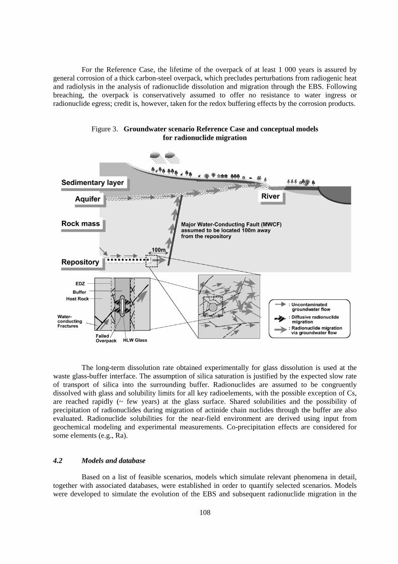
108
For the Reference Case, the lifetime of the overpack of at least 1 000 years is assured bygeneral corrosion of a thick carbon-steel overpack, which precludes perturbations from radiogenic heatand radiolysis in the analysis of radionuclide dissolution and migration through the EBS. Followingbreaching, the overpack is conservatively assumed to offer no resistance to water ingress orradionuclide egress; credit is, however, taken for the redox buffering effects by the corrosion products.
Figure 3. Groundwater scenario Reference Case and conceptual modelsfor radionuclide migration
The long-term dissolution rate obtained experimentally for glass dissolution is used at thewaste glass-buffer interface. The assumption of silica saturation is justified by the expected slow rateof transport of silica into the surrounding buffer. Radionuclides are assumed to be congruentlydissolved with glass and solubility limits for all key radioelements, with the possible exception of Cs,are reached rapidly (~ few years) at the glass surface. Shared solubilities and the possibility ofprecipitation of radionuclides during migration of actinide chain nuclides through the buffer are alsoevaluated. Radionuclide solubilities for the near-field environment are derived using input fromgeochemical modeling and experimental measurements. Co-precipitation effects are considered forsome elements (e.g., Ra).
4.2 Models and database
Based on a list of feasible scenarios, models which simulate relevant phenomena in detail,together with associated databases, were established in order to quantify selected scenarios. Modelswere developed to simulate the evolution of the EBS and subsequent radionuclide migration in the
109
rock surrounding the buffer material. These models are more detailed and realistic than those used inthe earlier H3 assessment and thus improve our understanding of key processes. The same can be saidof the corresponding databases.
The main radionuclide transport model used to represent EBS performance is based on one-dimensional diffusion with linear, reversible and instantaneous sorption. Distribution coefficients canbe determined from batch studies with uncompacted buffer material, or can be calculated frommeasured values for element-specific diffusion coefficients from compacted samples; the latter valuesare used in H12 because they reflect more realistic conditions in the EBS.
The impact of variations in parameter values for mass transport through buffer on release tothe far field is strongly affected by the boundary conditions. In H12, the diffusive flux from the bufferis balanced against the flux in groundwater flow through the excavation disturbed zone, as a morerealistic model based on integrated siting and design. The calculated dose result for the ReferenceCase indicates that sufficient containment and isolation of radionuclides can be achieved by the EBSand the near-field host rock, provided the host rock continues to provide a stable environment for theoperation of the EBS, and that the repository facilities are adequately designed and constructed (e.g.such that backfilling is complete and repository seals are effective).
Models and datasets for EBS modelling in H12 are derived from, and tested against, theresults of an extensive laboratory experimental programme in Japan. In particular, use is made ofengineering-scale experiments at the ENTRY facility, as well as radiochemical experiments undercontrolled repository-simulated conditions at the QUALITY facility. International scientific literatureand international validation projects (e.g. OECD/NEA and SKI, 1994; Ota et al., 2001) are alsoutilised. Natural analogue studies are also used to confirm the expected long-term performance of thekey engineered barriers and near-field processes. For example, analyses of degradation of volcanicglasses in various environments are utilised to support the low degradation rates for the borosilicateglass waste form.
4.3 Effectiveness and robustness of the EBS
The long containment times of radionuclides within the multiple barriers provided by thedisposal system means that most decay to insignificant levels before reaching the human environment.The decrease in the radiotoxicity of the contained radionuclides as a function of time was illustrated bymeans of a safety indicator termed the radiotoxicity index. The radiotoxicity index of a specificradionuclide within a specific system component has units of m3 and is here defined as the inventoryof that nuclide within the component (in Bq) divided by the maximum permissible activityconcentration for that radionuclide outside a designated monitored area (in Bq m-3) (STA, 1988). The“yardstick” was the radiotoxicity index of 5 x 10⁻⁵ km3 granite (which corresponds roughly to thevolume of rock above the area occupied per waste package- check this number!) with 1 ppm naturaluranium concentration.
Figure 4 shows the combined radiotoxicity index of all radionuclides in different systemcomponents as a function of time for the H12 Reference Case. The figure shows the substantial decayof radiotoxicity with time. The figure shows that radiotoxicity is contained predominantly within theengineered barriers of the repository at all calculated times. Only at times of around 106 to 107 years isa significant proportion of the total radiotoxicity present within the geosphere, by which time it hasdecayed by 5 orders of magnitude. The radiotoxicity of releases to the geosphere is always less thanthe natural radiotoxicity of 5 x 10⁻⁵ km3 of granite. At no stage is a significant proportion of theradiotoxicity present in the biosphere.

110
Figure 5 shows the maximum dose and the contributions of Cs-135 (dominant radionuclidefor the maximum dose for the Reference Case) and Th-229 (high radiotoxicity daughter of Np-237 anddomonant after about 5 million years for the Reference Case) as functions of transport distance in theundisturbed host rock expressed in terms of resultant dose which is calculated by introducing theradionuclide flux at that distance directly into the Reference Case biosphere. The dose decreasessharply as transport distance increases and becomes two orders of magnitude smaller within the firstten meters, illustrating the efficiency of the near-field host rock barrier for these nuclides.
Figure 4. The combined radiotoxicity index per waste package of all radionuclides in differentsystem components as a function of time for the H12 Reference Case
*5 x 10⁻⁵ km3 of granite with 1 ppm uranium concentration which corresponds roughly to the volumeof rock above the occupied area of a waste package
Figure 5. Maximum dose for various transport distances (40 000 waste packages)
111
4.4 Sensitivity and uncertainty analyses
Model and data uncertainty cases were analysed by considering a wide range of alternativemodels and parameter values. In addition, a number of calculation cases have been conducted forscenarios in which the geological disposal system is perturbed in the future by natural events andhuman activities. Based on the understanding of system sensitivity acquired through thesecalculations, a set of cases focusing on the key factors has been analysed for self-consistentcombinations of alternative geological environments and designs. Due to effects of uncertainties inmodels and data, alternative disposal systems and unlikely disruptive events, calculated values of themaximum annual dose vary significantly. However, none of them exceed the radiological protectionlevels proposed in foreign regulatory criteria or guidelines (100-300 µSv y-1).
5. Key uncertain areas and future priorities
In future stages of the Japanese programme, the engineered barriers will be optimised basedon consideration of site-specific geological data obtained during site characterised, and enhancedunderstanding of safety-relevant phenomena obtained by laboratory studies. This will allow morerealistic modelling to be carried out in PA, although some uncertainty will remain and a degree ofconservatism will still be included in order to ensure that confidence in safety margins can be derivedfrom PA findings.
The identified key uncertain areas are:
• Studies on the transient phase following emplacement
− Treatment of T-H-M-C-B coupled processes.− Perturbation by repository construction and operation.− Monitoring and QA strategy to justify the initial conditions for post-closure PA.
• Long-term alteration of buffer material
• Development of more reliable datasets, e.g. on characteristics of buffer material inter-actions with saline groundwater
• Characterisation of near-field geological conditions
− Treatment of spatial heterogeneity, especially groundwater flow through the EDZ.
• PA methodology for the whole repository system, taking into account, e.g. thegeometric complexity within the repository and effects of multiple sources.
Closer linkages between repository design, site characterisation and PA will also be needed.
6. Conclusions
The results of various R&D activities have been integrated to develop a safety case withinthe H12 project to demonstrate the technical reliability and safety of the Japanese geological disposalconcept. The basic argument that the proposed repository system is safe is based on functions intrinsicto the design, including barrier functions of the engineered system and the geosphere. To support theselection of potential sites, a methodology for safety assessment has been developed which focuses onthe performance of the near-field. This methodology consists of developing relevant scenarios and

112
realistic models, along with appropriate data, with a view to establishing the constraints on sites to beselected in the future which will ensure that safety guidelines are met.
The methodology developed in the H12 project provides a basis for the performanceassessment of a geological disposal system at a site to be selected in the future. At the site-specificstage it will be important to incorporate realistic geological features and optimised engineered barrierswithout compromising the robustness in the methodology that is essential to a defendable assessment.
References
AEC (1997): Atomic Energy Commission of Japan: Guidelines on Research and DevelopmentRelating to Geological Disposal of High-Level Radioactive Waste in Japan, Advisory Committee onNuclear Fuel Cycle Backend Policy.
AEC (2000): Long-term Program for Development and Utilization of Nuclear Energy, Atomic EnergyCommission of Japan (in Japanese).
Ahn, J. (1999): Long-Term Behavior of Bentonite Buffer in a Geologic Repository for High-LevelWastes, UCB-NE-4222.
Chijimatsu, M., Sugita, Y., Fujita, T. and Amemiya, K. (1999a): Coupled Thermo-Hydro-MechanicalExperiment at Kamaishi Mine, Technical Note 15-99-02, Experimental results, JNC TN8400 99-034.
Chijimatsu, M., Fujita, T., Kobayashi, A. and Ohnishi, Y.(1999b): Coupled Thermo-Hydro-Mechanical Experiment at Kamaishi Mine, Technical Note 16-99-03, Analyses of Task 2C,DECOVALEX, JNC TN8400 99-031.
Fujita, T., Chijimatsu, M. Sugita, Y. and Amemiya, K. (1998): Field Experiment of Coupled T-H-MProcessed in the Near Field, 1998 International Workshop, Key Issues in Waste Isolation Research,Barcelona.
Jing, L., Stephansson, O., Tsang, C-F. and Kautsky, F. (1996): DECOVALEX -Mathematical Modelsof Coupled T-H-M Processes for Nuclear Waste Repositories, Executive Summary for Phases I, II andIII.
JNC (2000): H12: Project to Establish the Scientific and Technical Basis for HLW Disposal in Japan,Project Overview Report and three Supporting Reports, JNC TN1410 2000-001~004, 2000.
Kanno, T. and Wakamatsu, H. (1991): Experimental Study on Bentonite Gel Migration from aDeposition Hole, Proc. 3rd Int. Conf. Nuclear Fuel Reprocessing and Waste Management(RECOD ’91), Sendai.
Mikoshiba, M., Ogawa, N. and Miwa, T. (1995): Research on the Vibration Behavior of DeepUnderground Cavities and Structures, Science and Technology Agency, FY 1995, NationalOrganization for Atomic Energy Test Research, Progress Report, No.34 pp.21-1-21-6 (in Japanese).
Mikoshiba, M., Ogawa, N. and Miwa, T. (1996): Research on the Vibration Behavior of DeepUnderground Cavities and Structures, Science and Technology Agency, FY 1995, NationalOrganization for Atomic Energy Test Research, Progress Report, No.35 pp.19-1~19-6 (in Japanese).
OECD/NEA and SKI(1994): GEOVAL’94 Validation Through Model Testing, Proceeding of anNEA/SKI Symposium, Paris, France, 11-14 October 1994.
113
Ota, K., Alexander, W.R., Smith, P.A., Möri, A., Frieg, B., Frick, U., Umeki, H., Amano, K., Cowper,M.M. and Berry, J.A. (2001): Building confidence in radionuclide transport models for fractured rock:the Nagra/JNC Radionuclide Retardation Programme. Sci. Basis Nucl. Waste Manag. XXIV,pp. 1033-1041. NEA/SKI Symposium Paris, France, 11-14 October 1994.
PNC (1992): Research and Development on Geological Disposal of High-Level Radioactive Waste:First Progress Report (H3), PNC TN 1410 93-059.
Pusch, R. (1981): Borehole Sealing with Highly Compacted Na Bentonite, SKBF/KBS TechnicalReport 81-09.
Pusch, R. (1983): Stability of Bentonite Gels in Crystalline Rock-Physical Aspects, KBS TR83-04.
STA (Science and Technology Agency) (1988): Notification No.20 (in Japanese).
Suzuki, H., Fujita, T. and Kanno, T. (1996): Water Potential and Water Diffusivity of Buffer Material,PNC TN8410 96-117 (in Japanese).
Takaji, K., Sugino, H., Okutsu, K., Miura, K., Tabei, K., Noda, M., Takahashi, S. and Sugie, S.(1999): Evaluation of Long-Term Mechanical Stability of the Near-Field, JNC TN8400 99-043 (inJapanese).
Tanai, K., Sato, H., Murakami, T. and Inoue, M. (1999): A Preliminary Assessment of Gas Diffusionand Migration, JNC TN8400 99-045 (in Japanese).
Taniguchi, W., Takaji, K., Sugino, H. and Mori, Y. (1999): Evaluation of Seismic Stability of the NearField, JNC TN8400 99-054 (in Japanese).
Umeki, H. (2000): Key Aspects of the H12 Safety Case, MRS 2000, 24th International Symposium onthe Scientific Basis for Nuclear Waste Management, August 27-31, 2000, Sydney, Australia.

115
ON-GOING ACTIVITIES OF THE EC PROJECT “BENIPA”CURRENT STATUS, KEY ISSUES AND ACHIEVEMENTS
Jesús AlonsoENRESA, Spain
Abstract
BENIPA (Bentonite Barriers in Integrated Performance Assessment) is a research project,within the Fifth Framework Programme of the European Union, which was started on September 2000and is has a duration of 36 months. Participants in the project are: 2 National Agencies, which areresponsible for national HLW management (ENRESA as Project Co-ordinator, Spain and NAGRA,Switzerland) and 6 Research Centres (GRS, Germany; IRSN, France; NRG, The Netherlands;SCK•CEN, Belgium; VTT, Finland and ZAG, Slovenia).
The overall objective of BENIPA is to assess the state of the art in the treatment of bentonitebarriers in Integrated Performance Assessment, evaluating the capacity and consistency of methodsand data available to convincingly justify the capacity of bentonite to perform their assigned safetyfunctions.
During the first part of the project different bentonite barrier concepts have been reviewedand four reference cases have been defined for the modelling work in the project. FEP’s Databaseshave been created and the scientific and technical bases for the analysis of bentonite barriers have beenreviewed. In the second part of the project, as a step previous to modelling, an analysis of models forthe mechanical, hydrological, thermal and chemical conditions is carried out, along with a review ofthe needs in input data.
In BENIPA, calculations at process and integrated level are currently being performedamong different codes to check consistency and sufficiency or complementarily for fulfilling the needsof performance assessment. However, since it is too early to present some of the results or even theindividual contributions of the partners, the modelling and calculations being currently carried out byENRESA will be advanced, just as a representative example of the work going on.
This paper summarises the work already done in BENIPA and provides with illustrations ofthe modelling work consisting of the approach followed by ENRESA in applying three codes:CODE_BRIGHT, CORE2D and GOLDSIM. The processes considered, simplifications adopted,limitations imposed and preliminary findings of the work are mentioned along.

116
1. Introduction
The engineered barriers in the near-field of most repository concepts for high level wastesand spent fuel, in crystalline and clay host rocks, call for the use of significant amounts of bentonitebased materials (hereafter called bentonite barriers) interposed as a buffer between the waste packagesand the host rock.
Considerable resources and time has been and is being devoted to the study and testing ofbentonite barriers, focusing alternatively on diverse aspects at different levels of detail, and differentscale and time horizons. This effort is being pursued in a continuous process for confidence buildingand optimisation, justified by the importance of bentonite barriers for the safety, and for the design,operation and closure of the repository systems. The increasing body of knowledge and multiplicationof methods and tools of assessment available strongly outline the need of an overall analysis of theachievements and trends in respect of what is needed and/or desirable in this field.
On the other hand, the behaviour of bentonite barriers in the repository environment isinfluenced by mechanical, hydrological, thermal, chemical and radiological conditions, which arevariable in both time and space. However, integrated performance assessment should assume a moreor less large degree of abstraction and simplifications due to:
• Difficulty to account for heterogeneity and variability along the space and time.• Uncertainty in some of the input data for the models.• Difficulty to model some significant processes (gas flow, colloids, THMC coupling, etc.)
To assess all these topics several European countries have integrated their skills, knowledgeand experience in a project. BENIPA (Bentonite Barriers in Integrated Performance Assessment) is aresearch project, within the Fifth Framework Programme of the European Union, that focuses on therole of bentonite barriers in the performance of deep repositories for the disposal of spent fuel andvitrified high-level waste in granite and clay formations.
BENIPA was launched on September 2000 and has a duration of 36 months. Participants inthe project are 2 national agencies and 6 research centres. ENRESA is the Co-ordinator of the Project.
Table 1. Participants in BENIPA
Country Partner Profile
Spain ENRESA National Agency
Switzerland NAGRA National Agency
Belgium SCK·CEN Research Institute
Finland VTT Research Institute
France IRSN Research Institute
Germany GRS Research Institute
Netherlands NRG Research Institute
Slovenia ZAG Research Institute

117
The project is structured in work-packages (WP), which cover: from the state of the art andknowledge available regarding bentonite barriers to the analysis and comparison of specific resultsobtained using different models. The different work packages and tasks are developed in parallel forrepositories in clay and in granite.
• WP1 is a review of the bentonite barrier concepts and their role in repository safety onthe base of former performance assessment conclusions [2]. Also, the reference cases forthe calculations are selected [3].
• WP2 compiles two list of FEP’s, one for clay and one for granite [4], and describes thescientific and experimental bases for the bentonite barriers [5].
• WP3 gives a detailed analysis of the different models and computer codes used atdetailed process level and at integrated level [6]. Input data for the models are generatedand justified [7]. The focus of the analysis is on the conceptual consistency among thedifferent models and their complementarily and sufficiency for fulfilling the needs ofIntegrated Performance Assessment.
• In WP4 calculations are performed at process and at integrated level with improvedmethods to evaluate the significance of processes and scenarios. Sensitivity andoptimisation analysis are also part of this work package.
• WP5 consists of the co-ordination and integration work along the project, and theevaluation of the results and the derivation of overall conclusions.
WP1, WP2 and most of WP3 have been finished during the first part of the project. BENIPAis currently immersed in WP4. Calculations at process and integrated level are being performed amongdifferent codes to check consistency and sufficiency or complementarily for fulfilling the needs ofperformance assessment. However, it is too early to present in this paper the final results or even theindividual contributions of the partners; the modelling and calculations being currently carried out byENRESA, referred to its own repository concept, will be introduced in the following, just as arepresentative example of the work to come.
The codes used by ENRESA are CODE_BRIGHT, CORE2D and GOLDSIM. The processesconsidered, simplifications adopted, limitations imposed and preliminary findings of the work arementioned along.
2. Project description. Process and model analyses
The first half of the project was dedicated to compile the relevant information, to generateproject FEP databases and to analyse the basic data and available models for the assessment ofbentonite barriers.
A synthesis of the engineering concepts using bentonite as a barrier in repositories in both crystallineand clay rock has been carried out. The design functions summarised for bentonite barriers are thefollowing:
• Stabilise and support openings and reduce shearing forces on containers.• Seal rock fractures and fissures.• Allow canister emplacement keeping the canister in position.• Provide a chemical environment, minimising container corrosion and radionuclide
solubility.
118
• Provide a low-hydraulic conductivity around the canister.• Retard the diffusion-controlled transport of many dissolved radionuclides.• Filter colloids that may be form in the inner space of the barrier.• Allow release of gas produced by metal corrosion and heat transfer from the canister to
the rock.
Four reference cases have been defined for subsequent modelling and calculating activities.They are based on specific concepts from existing programs for both the granite and clay options. Tworeference cases have been selected within granite repository concepts. These are the vertical holeemplacement and the tunnel emplacement options. The reference case for the vertical holeemplacement is based on the KBS-3 repository design whereas for tunnel disposal it is that ofENRESA (FEBEX) concept. For the clay two different options have been selected too, one for “stiff”clay and the other for plastic clay, both with a tunnel design. The reference case for a repository inmudrock is from NAGRA, whereas the reference case for the plastic clay is from NIRAS/ONDRAF.
Regarding the process analysis, a compilation and elaboration of FEP’s relevant for theperformance of bentonite barriers has being produced for the granite and clay options and comparedwith the NEA International FEP’s Database and some national databases. FEP Databases in BENIPAtry to avoid typical problems sometimes found in other FEP Databases as: lack of consistency in thelevel of discrimination between FEP’s, redundancies and overlapping, and excessive generality or, onthe contrary, excessive detail in the descriptions. The approach adopted is based on a systematic,hierarchical structure
Also, a project handbook of relevant data for safety assessment of bentonite barriers, withappropriate references for usage in the project has been produced. To this aim, a significant amount ofdata was compiled covering the knowledge on bentonite barriers obtained in laboratory, rocklaboratory, in situ experiments, natural analogues theoretical studies and reviews. The informationobtained is collected in more than one hundred cards, summarising work carried out in all thecountries involved in BENIPA, and in Sweden, in Canada and in Japan. The following are someillustrative examples of important issues identified in this document.
• The problem of isolating the “true” porewater, to obtain reliable data on pore waterchemistry in very low permeable and scarce water-content clay systems, has not beensolved yet. Modelling of the pore water is proposed as a means to obtain representativepore water chemistry at initial conditions instead of using the chemical compositions ofthe pore water obtained in tests for high solid to liquid ratios (squeezing and seep water).
• In transport models bentonite parameters are assumed to be constant along the time. Thelong-term effects of heat and radiation on bentonite transport parameters are not wellknown.
• For the time being, tests performed in odometers have not permitted good dimensionalcontrol of bentonite samples. As a consequence, fictitious saturation degrees over 1 havebeen obtained. New tests performed at different temperatures are required to describethe thermal effects on retention curves.
• Kd values in batch experiments are not representative for compacted bentonite. Preferredtransport parameters to measure are De and Da.
On the other hand, BENIPA carries out an analysis and cross comparison of the differentmodels available for the numerical simulation of the behaviour of bentonite barriers. Also, the capacity

119
of characterisation methods and measuring techniques to satisfy input requirements of the models isevaluated.
The analysis provides an overview of the process level models and integrated level modelsthat are used in BENIPA. The potential roles of these models in performance assessment and inparticular their consistency, complementarity and applicability have been investigated.
Aspects such as the theoretical bases on which specific models are built and their past useshave been extensively covered. Similar models and codes were compared to assess whether the modelscover the FEP’s identified in BENIPA and to identify possible roles of these codes in performanceassessment. Fourteen computer programs have been considered in BENIPA.
Table 2. Classification of codes used in BENIPA
PORFLOWTOUGH2CORE2D
Transfers inporous media
Mapping of FEP’s
CODES
USED
CORE2D
HYTEC
CODE_BRIGHTCAST3MFLAC 3D
FLAC
BENIPA MODELS
CHETMADGOLDSIMGRAPOSREPCOMSTMAN
MELODIEPORFLOW
Integratedlevel
ReactivetransportT-H-M
Process level
Some of the codes are commercial but others have been developed within nationalprogrammes and the developers either participate in the project or are available for consultation.
3. Project description. Modelling and calculations
Modelling and calculations are being carried out, at process level and integrated level forboth normal evolution and other specific scenarios, on the BENIPA reference cases. The results arebeing analysed and compared from the point of view of consistency and complementarily of theavailable models. The purpose of detailed process level is to investigate the significance of specificphenomena and to provide inputs to other calculations, namely at integrated level, so that they cansupport the initial assumptions and provide the bases for selecting input data. A second set ofcalculations will be performed and their results analysed to investigate the sensitivity and margins ofoptimisation of bentonite barrier performance. Sensitivity and optimisation analysis will include threetypes of calculations, namely: local sensitivity analysis, global sensitivity analysis and optimisationanalysis.

120
The calculations at process level address the following main phenomena:
• thermal processes;• mechanical processes;• hydraulic processes;• geochemical processes;• transport by colloids;
The scenarios being considered in BENIPA are:
• normal evolution scenario;• altered evolution scenarios:
– migration in a post emplacement (pre-closure phase);– transport of radionuclides in case of accidental drilling (includes modelling the
behaviour of a hole in the barrier in case of accidental drilling):– early canister failure, taking into account the transient temperature field.
As was previously indicated in the Introduction, no final WP4 calculations are yet available.Preliminary calculations carried out by ENRESA are refereed here just as illustrative examples. In thefollowing only the modelling of the tunnel concept in granite case will be presented.
In ENRESA reference case for tunnel emplacement in granite the fuel elements areincorporated in cylindrical carbon steel canisters measuring 4.54 m in length and 0.90 m in diameter.The canisters are emplaced in cylindrical receptacles, constructed with blocks of compacted bentoniteinside horizontal drifts, measuring 500 m in length and 2.4 m in diameter. A separation of 2 mbetween canisters has been established, and of 35 m between disposal drifts, in order not to exceed atemperature of 100ºC in the bentonite.
Figure 1. Reference case for granite – tunnel emplacement

121
3.1 ENRESA’s T-H-M modelling
Evaluation of repository evolution involves consideration of coupled processes induced by thechanges in thermal, hydrological and mechanical conditions. ENRESA’s aims for the T-H-Mcalculations are:
• Predict the evolution of the temperature and water saturation. The temperature in thebuffer should remain below the limit of 100ºC to avoid boiling in the unsaturated phaseand to reduce the likelihood of alteration of the bentonite that could degrade thedesirable swelling properties.
• Predict the stresses generated by the expansion of the corrosion products and theincrease of temperature.
CODE_BRIGHT is a code especially well suited to model the thermo-hydro-mechanicalbehaviour of the bentonite. The equations solved by the code result from substitution of constitutiveequations and equilibrium restrictions into balance equations of mass, linear momentum and energy.The result is a system of partial differential equations in the following variables: solid displacements,liquid pressure, gas pressure and temperature. Darcy’s and Fick’s laws replace the balance ofmomentum for phases and components in phases, respectively. These laws are considered in the set ofconstitutive equations, which also include, among others, the mechanical model, the retention curveand Fourier's law. The assumption of phase change equilibrium of water or air in gas phase and liquidphase leads to the psychometric law and the Henry's law, respectively.
The dimension of the 2-D finite element mesh of ENRESA’s T-H-M model is 17.5 x1 000 m2. The input data for the bentonite were obtained from the experiments of the FEBEX projectand the constitutive models have been validated for this project. The initial saturation degree of thebentonite is 0.66. The value of the initial suction is 44.41 MPa. The temperature at 500 m is 30.5ºCand the geothermal gradient is 0.035ºC/m. The granite is considered isotropic and homogeneousmaterial.
The Figure 2 represents the temperature evolution of some selected points in the bentonite:near the heat source, in the middle and near the outer part of the bentonite. The maximum temperatureobtained was 95.2ºC, 26.3 years after the disposal of the canister. At this time, the outer part of thebentonite has 75.8ºC. During the first years the thermal gradient is high due to the high thermal powerof the spent fuel. After 1 000 years, the thermal gradient across the buffer becomes uniform. The timeneeded to recover the original temperature is higher than 40 000 years.

122
Figure 2. Temperature evolution in the bentonite
The evolution of the saturation degree is shown in the Figure 3. The time needed to saturatethe bentonite is 7.4 years. This result is very sensitive to the retention curve of this material. At thebeginning the inner part of the bentonite becomes dry due to the high temperatures. This dryingprocess is less important in the outer part of the bentonite due to the lower temperatures. The totalmaximum stress is 11 MPa, being the sum of the swelling pressure of the bentonite and the hydrostaticpressure. The thermal expansion of the rock generates stresses. Due to the dimensions of the modeland since the system is confined between the laterals the only way to release stresses is towards theground surface.
Figure 3. Evolution of the saturation degree in the bentonite

123
Conclusions extracted from the T-H-M calculations carried out are:
• The temperature in the buffer remains below the 100ºC constraint.
• The resaturation process of the bentonite is quick and it homogenises the buffer materialdue to the swelling process.
• The buffer absorbs the stresses generated by the thermal expansion of the repositorymaterials by means of its favourable plasticity characteristics.
3.2 ENRESA’s Geochemical modelling
The groundwater saturates the bentonite barrier and dissolves some accessory minerals. Asresult of this interaction the porewater evolves. The chemistry of the porewater (concentration ofdissolved species, Eh, pH) as well as the chemical gradients may influence the chemical and physicalproperties of the bentonite materials, the corrosion rate of the canister, and the transport properties ofthe radionuclides. ENRESA’s near field geochemical model for BENIPA predicts the evolution of theporewater composition, considering advection, diffusion, mineral dissolution and precipitation,aqueous complexation, cation exchange and surface adsorption. The bentonite porewater and theboundary groundwater tend to reach the equilibrium by diffusion. The calculation of the geochemicalevolution provides at different time steps the concentration of the majority of species in the bentonite,the evolution of pH and Eh, the precipitation and dissolution of accessory mineral phases and the finalcomposition of the exchange complex.
The computer code used for the calculations is CORE2D, which solves solute transportcoupled with chemical equilibrium and kinetics of reactions taking place in the aqueous phase such asacid-base, redox and aqueous complexation or in the solid phase such as surface adsorption, ionexchange, mineral dissolution and precipitation. Thermal coupling is taken into account forthermodynamical constant reaction adjustment. CORE2D is based on the sequential iteration approachto solve the coupled hydrological transport processes and hydrogeochemical reactions, which aresolved separately in a sequential manner following an iterative procedure. The finite element methodis used for spatial discretization, while implicit, explicit and general finite difference schemes are usedfor time discretization.
A simplified 2D-axisymmetric model (a cylindrical slice) is considered. Bentonite, EDZ andseveral meters of rock, in order to take into account properly the boundary conditions, have beenmodelled as homogeneous and isotropic porous media. Values for hydraulic conductivity, diffusioncoefficient, dry density, porosity, thermal conductivity and heat capacity are assigned to eachcomponent of the model. Every material can be split in several zones each one with particularporewater, mineral composition, ion exchange capacity and adsorption properties. The mineralcomposition of the bentonite and the porewater chemical composition of bentonite and groundwaterdefine the initial conditions. The hydraulic flow at the bentonite/granite interface and the temperatureevolution define the boundary conditions.
An initial calculation is needed in order to obtain the porewater composition of the saturatedbentonite. This calculation takes into account the mixing of the non-saturated bentonite porewater withthe granite groundwater and the interactions with the solid phase; mainly the dissolution of theaccessory minerals and the cation exchange. The chemical evolution of the porewater during thesaturation process is then calculated. The results in the middle point of bentonite 100 years are used asinput for the geochemical model in saturated conditions. The time frame for the calculation is one

124
million years. In this period, the geochemical environment evolves to alkaline and reducing conditionsas it is shown in Figure 4. There is a thermal effect on the pH and pe behaviour. At the beginning ofthe calculation the temperature is over 85ºC. At this moment the neutral pH is around 6.25. Redoxevolution is close related to Fe+2 behaviour.
Figure 4. Evolution of the pH and pe in the bentonite
The concentration of the aqueous geochemical components, shown in Figure 5 evolves fromthe initial bentonite porewater values to the granite groundwater values. The velocity of this evolutiondepends on the diffusion coefficients and the groundwater flow in the granite. In the time periodconsidered the porewater concentration does not reach the groundwater level.
Figure 5. Concentration of chemical components in the bentonite porewater
1,E-07
1,E-06
1,E-05
1,E-04
1,E-03
1,E-02
1,E-01
1,E+00
1,E+02 1,E+03 1,E+04 1,E+05 1,E+06
Time (years after saturation)
HCO3-
Cl
SO4-2Ca+2
Mg+2
Na+
K+
Fe+2

125
Except for carbonates, the concentrations of the main species are higher in the bentoniteporewater than in the original groundwater. This situation originates the migration of the species frombentonite to granite. Precipitation and dissolution of calcite is important close to the bentonite/graniteinterface. Finally, by the end of the simulation the calcite precipitated begins to dissolve raising thepH. Conclusions extracted from the geochemical calculations carried out are:
• The bentonite is a very good chemical buffer for high pH due to its contents in alkalineregulators, (calcite and anhydrite) and the contribution of the cation exchange. Thepresence of magnetite as the corrosion products of the canister controls the ionic pairFe+3/Fe+2, guarantying the redox regulation.
• It is not expected to have strong variations in the geochemical environment for a millionyears, therefore, radionuclide solubilities for transport calculations are to be provided fora definite range of conditions.
• The up scaling of the results to the whole repository needs to take into consideration thespatial variability of the parameters, mainly the in-situ temperature and the chemicalcompositions. A range of variability of these parameters has to be considered to link theresults to the overall performance.
3.3 ENRESA’s integrated transport model
After canister failure, the groundwater reaches the waste and radionuclide release starts.Three different contributions are considered: a) the inventory in the pellet-cladding gap and UO2 grainboundaries, released instantaneously after canister failure, b) the activation products in the claddingand structural components, released in 1000 years at a constant rate and c) the inventory in UO2
matrix, that contains most of the radionuclides in a fuel element. The inventory in the UO2 matrix isreleased slowly, congruently with the matrix oxidation due to alpha analysis.
The geochemical evolution of bentonite porewater provides the solubility limits for thedifferent chemical species. Radionuclides released from the waste dissolve or precipitate in the freewater around the waste, depending on their solubility limits. Radionuclide concentration in the wateraround the waste is the boundary condition at the inner surface of the bentonite for transport throughthe bentonite barrier. Due its low hydraulic conductivity, transport through the bentonite is controlledby diffusion. At the outer surface of the bentonite the radionuclides diffuse into the granite in theExcavation Damaged Zone (EDZ) and the intact granite beyond the EDZ. Since water flows throughthe granite parallel to the galley axis, both advection and diffusion are considered in the granite.
The computer code used for the transport calculations is GoldSim, which includes analgorithm of mixing cells to simulate radionuclide transport in porous media. The physical system isdiscretised into several mixing cells that are linked together using advective and diffusive connections.Within a cell, all species mass is assumed to be instantaneously and completely mixed and equilibratedamong all of the media in the cell: liquids and solids. When multiple cells are linked together, thebehaviour of the cell network is mathematically identical to a network of finite difference nodesdescribing a coupled system of differential equations.
The mixing cells allow modelling all the relevant transport processes: precipitation/dissolution, isotopic dilution, anion exclusion, sorption on porous media and radioactivedecay/ingrowth. Figure 6 shows the near field model. The magnitude used to quantify the performanceof the bentonite, as a transport barrier, is the activity flux released released from the near field for eachradionuclide.

126
Figure 6. Compartment model used in transport calculations
�����
������ ����������� ������
�����
�����
������ ���� ����� ����
������ ����
�������
��� ��� !
"������#
$�������
%���
&����'���
%������
&��'������
In order to gain confidence in the models developed, preliminary transport calculations wereperformed for 3 stable species with different transport parameters (cation, anion and neutral species)for both solubility limited inputs and delta pulse inputs (six different calculations). Results werecompared with those obtained by VTT, for the same reference case being the agreement very good.
After preliminary calculations complete calculations were carried out. Radionuclide releaserates from the near field are shown in Figure 7. Only radionuclides with peak release rate greater than1Bq/y are shown in the figure. Releases from the near field of weakly sorbed or non-sorbed speciesstart early after canister failure, while sorbed species are significantly delayed.
Figure 7. Release rates from the near field (Bq/yr-canister)

127
Transport calculations show that radionuclide release rates from the near field are quitesmall. To put these releases into perspective, a dose calculation was carried out assuming that theradionuclides released from the near field of the entire repository are discharged directly to thebiosphere (transport in geosphere is ignored). This means that the releases are assumed to be dissolvedin a river of 1E6 m3/yr flow rate. Doses are calculated multiplying the activity concentrations by theradionuclide-specific Biosphere Dose Conversion Factors calculated for a Spanish biosphere. Totalpeak dose is about 2E-5 Sv/yr, well below the Spanish reference value of 1E-4 Sv/yr. Conclusionsextracted from the integrated transport calculations carried out are:
• The bentonite is a very efficient barrier in delaying and limiting the releases ofradionuclides. If low groundwater flows are expected in the near field, the bentonitebarrier by itself can ensure acceptable releases and doses to the biosphere.
• Releases from the near field are controlled by high-solubility radionuclides, such asC-14, I-129, Cl-36, Ni-59 and Cs-135. Low solubility represents a very useful chemicalcharacteristic for limiting radionuclide transport.
• The very similar results obtained by VTT and ENRESA in the calculations of the samereference case increased the confidence in the codes (REPCOM and GoldSim) used byboth organisations in their PA exercises.
References
[1] Bentonite Barriers in Integrated Performance Assessment. BENIPA. Description of Work.Waste Management and Disposal Project FIS5-1999-00116. Document RevisionNo. 1/13.04.2000.
[2] BENIPA Project. Overview of Disposal Concepts for Clay and Granite. Deliverable D1. Rev. 0.March 2001.
[3] BENIPA Project. Reference Cases for Analysis. Deliverable D2. Rev. 0. May 2001.
[4] BENIPA Project. Treatment of Bentonite Barriers Related FEP’s in Integrated PerformanceAssessment. Deliverable D3. Rev. 0. January 2002.
[5] BENIPA Project. Project Handbook of Relevant Data for Safety Assessment of BentoniteBarriers. Deliverable D4. Rev. 0. February 2002.
[6] BENIPA. Analysis of Models Applicable to the Assessment of Bentonite Barriers. DeliverableD5. Rev. 0. December 2002.
[7] BENIPA Project. Data Generation Process. Deliverable D6. Rev. 0. April 2002.

129
APPENDIX C
REMIT AND COMPOSITION OF WORKING GROUPS

131
WORKING GROUPS REMIT
The workshop will concentrate on identification of issues related to the EBS and on itsintegration into the overall safety case, and discuss approaches to resolve these issues. In particular,the workshop should come to a final conclusion on the desirability and feasibility of an internationalproject in this area. This project should follow the same format as for GEOTRAP with a series ofworkshops that will be a useful platform for exchanges between radioactive waste organisations andthe scientific community on the EBS.
The major opportunity to provide input into the workshop conclusions and, therefore,proceedings will be during the Working Group sessions. In order to design the outlines of thesubsequent Workshops, the main tasks of the Working Groups are:
• To compile relevant issues from the point of view of addressing them in a practicalmanner within an international co-operative project;
• To confirm early suggestions or provide new suggestions on the contents of thesubsequent workshops.
The Working Groups will aim to set definite topics and priorities in order to plan a focusedand efficient project. The Programme Committee feels that suitable topics should be judged based on:
• Relevance and applicability within the current safety cases/assessments: it should beclear that the series of workshops will not work on issues simply for their interest from aresearch point of view but will be a platform for integration of sciences into safety.Therefore, the experience of many of the participants in the preparation of current safetycases should be brought to bear in this context.
• Exchange of strategies, approaches and relevant experience. The series of workshopswill share knowledge and experience about the integration of the four perspectivesregarding the EBS, namely engineering design, characterisation, process modelling, andperformance assessment, in order to understand and document the state-of-the-art andidentify the key common issues or uncertainties that need to be resolved. However, ifsignificant progress is judged unlikely to be made within a three- to five-year timeframe, it might be best to give these issues a lower priority compared to other issues thatare demonstrably of greater importance and urgency to establishing the technical basisof repository safety cases.
During the working group discussions, participants should answer the following questions:
• What are the arguments for or against international co-operation on these potentialissues?
• To what extent are participants prepared to discuss in detail the approaches made intheir national programme?
• Are the proposed issues relevant and of significant impact for an internationalworkshop? What issues need to be modified, clarified, created?

132
Suggestions for the subsequent Workshops
The Working Groups are also asked to discuss the potential modes of operation, inparticular:
• The appropriateness of the number of proposed workshops. If a Working Group feelssome of the proposed workshops might be combined, or if a topic proposed into theprevious version of this programme is more relevant, the Working Group should explaintheir reasoning and propose the new content of the combined workshops.
• The relevant perspective, expertise and experience of participants.
• Progress to be anticipated through the series of workshops.

133
Working Group A
DESIGN-CRITERIA AND CONSTRUCTION
Chairperson: Paul GierszewskiRapporteur: Frédéric Plas
Introductory presentation by Alan Hooper, United Kingdom Nirex limited “The selectionand Specification of Engineered Barriers for the Nirex Phased Disposal Concept”.
Within the multi-barrier system, the EBS itself comprises a variety of components, such asthe waste form itself, waste canisters, backfill, seals, and plugs. The general purpose of an EBS is toprevent and/or delay the release of radionuclides from the waste to the repository host rock, at leastduring the first several hundreds of years after repository closure when fission-product content is high,where they might be mobilised by natural groundwater flow. In many disposal concepts, the EBS,operating under stable and favourable geosphere conditions, is designed to contain most of theradionuclides for much longer periods.
The specific role that an EBS is designed to play in a particular waste disposal concept isdependent on the conditions that are expected (or considered possible) to occur (“scenarios”) over theperiod of regulatory interest, regulatory requirements for waste containment, and the anticipatedperformance of the natural geologic barrier. To be effective, an EBS must be tailored to the specificenvironment in which it is to function. Ensuring that an EBS will perform its desired functionsrequires an integration, often iterative, of site-characterisation data, data on waste properties, data onengineering properties of potential barrier materials, in situ and laboratory testing, and modelling.
In addition, the development of a concept implies the concrete definition of the differentcomponents of the system to be constructed to accommodate the waste packages, taking account ofthe different types of package and the volumes concerned, to preserve the possibility of retrievingthese packages and to contain the radionuclides over long periods of time.
SCOPE
• Role played by the EBS at different time scales, in the overall PA and safety case.• Components of the EBS.• EBS-design options to mitigate adverse effects (e.g. criticality, emplacement, etc.).• Baseline assumptions underlying the design.• Implication of retrievability on design.• Implication of step-wise decision-making process to the design evolution and/or optimisation.• Implication of regulations on the design.• Key lessons from peer reviews (internal /external).• Main EBS experiments in the URL.

134
• Key uncertainties/outstanding issues regarding the design and emplacement of the EBS• Estimation of “initial” conditions for post-closure modelling.• Options for testing and characterisation of properties and conditions (expected/ altered).• Implications/opportunities for monitoring and testing.
135
Working Group B
THERMO-HYDRO-MECHANICAL (THM) PROCESSES
Chairperson: Mick AptedRapporteur: Robert MacKinonn
The excavation, the construction of the EBS and the operation of the repository causeimportant changes in the stress regime and the hydraulic conditions of the geological media; theprogressive closure and sealing of the repository are important steps in the evolution of thehydromechanical evolution of the system, where the EBS and the host formations mutually interact.Furthermore, heat generating wastes modify the temperature of the system, and thereby the thermo-hydro-mechanical evolution through different coupled processes. In the medium and long term,changes in the environmental conditions and alterations in the properties of the EBS materials mayalso originate changes that may be of relevance for the performance of the system.
Design and ultimate performance of an EBS are not dependent solely on the undisturbedconditions and properties of the repository host rock, but also on how those conditions and propertiesmay change as a result of repository construction and operation and waste emplacement. These“repository-induced influences” evolve with time in a complicated interaction with the EBS.
The manner in which the properties and THM conditions in the host rock are affected by arepository is dependent on such factors as the rock excavation methods used, the duration ofoperations prior to closure, the heterogeneities and discontinuities in the host rock, the engineeringmeasures taken to maintain excavation stability and reduce water inflows, the chemical andmechanical properties of the materials used for backfilling and sealing, and the thermal load to whichthe rock is subjected.
SCOPE
• Significance of rock properties and EDZ on THM processes.• Definition of causes (near-field FEP’s) of repository-induced influences on EBS.• Effects of repository-induced influences on EBS.• Temporal evolution of conditions.• Changing saturation with time.• Interactions/coupling among processes and mechanisms.• Effects of THM processes on radionuclide transport• Interactions (definition and effects) among sealing materials, backfill, waste canisters, other
repository contents, and near-field host rock (internal FEP’s).• External FEP’s considered (e.g. tectonic movements).• Implication of temporal evolution of barrier properties.• Need for modelling of coupled THM processes over the different time scales.

136
• THM effect of waste packages.• Treatment of uncertainty and variability; key issues.• Gas migration, gas effects on EBS.• Key issues related to boundary conditions in models.• Characterisation of parameters: surface laboratory, URL, natural analogues.• HM effects of corrosion products.• Geometric complexity related to different locations within the repository.• Non-conformance of emplaced EBS, validation of averaging (deviation from the initial
conditions).
137
Working Group C
GEOCHEMICAL PROCESSES
Chairperson: Medhi AskariehRapporteur: Patrik Sellin
There is a large diversity of geochemical FEP’s that are relevant for the performance of ageological repository. The main transport mechanisms for radionuclides are advection-dispersion-diffusion of dissolved species in groundwater. Many radioactive species have limited solubility,depending on the geochemical environment. Furthermore, migration may be significantly retarded bysolid-solute interactions; on the other hand several FEP’s may enhance migration, as transport incolloidal form and formation of complexes. The mobilisation of the radionuclides is controlled at thestart by the performance of the waste form, whose degradation is influenced by the environmentalconditions in the near field. Chemical processes are also relevant to the EBS integrity and near-fieldperformance by causing the changes in the EBS materials and the near-field host rock.
In many performance assessments, evolution of chemical and physical conditions of theEBS and near-field rock are analysed for a single waste package whose characteristics are derived bytaking an ensemble average among many thousands of packages in a repository. In these analyses,effects of fluctuations in the EBS fabrication/emplacement conditions and spatial heterogeneity in thesurrounding rock mass are "smeared out". In reality, the initial conditions at every waste packagelocation will deviate to a certain extent from such an idealised representation.
Differences in spatial emplacement of waste packages within rooms (e.g., centre location,edge location, or corner location) and spatial positions of rooms within repositories, combined withnatural geologic heterogeneity in the near-field host rock, will cause different evolutions of packagedegradation, leading to perhaps different times of contact by water, different times ofcontainer/overpack failure, or different rates of release of radionuclides from the waste form oncecontainment is lost.
In addition, one can imagine a number of situations where material incompatibility betweenbackfill, plugs, and tunnel supports, which are designed mainly focussing on their own functions,might compromise performance of the safety barriers. For example:
Chemical reactions of cementitious materials with groundwater raise pH of near-field porewater. Elevated solubilities and reaction rates of many alumino-silicate phases (including borosilicateglass and buffer minerals) under such a condition might result in enhanced dissolution of these phasesand precipitation of secondary minerals such as CSH gel and zeolites. These changes may alter theperformance of such barriers selectively along the paths where the hyper-alkaline plume andradionuclides migrate.

138
Chemical degradation of tunnel supports, together with reduced swelling capability of buffermaterial due to action exchange with concrete leachate, can lead to formation of additional flow pathsalong tunnels.
SCOPE
• Definition of causes (near-field FEP’s) of repository-induced influences on EBS.• Effects of repository-induced influences on EBS ; Interactions/coupling among processes and
mechanisms.• Modelling approaches, coupling, implications for far-field source term; temporal evolution of
conditions.• Conceptual model and parameter uncertainty.• Relevant aspects related to corrosion products.• Identification and relevance of stray materials.• Key issues related to the solubility limits; determination and handling of uncertainties.• Effects on radionuclide transport.• Implications of heterogeneity in optimising design and repository layout.• Non-conformance of emplaced EBS, validation of averaging.• Methods of characterising variability in processes and properties.• Scaling from the laboratory scale to the waste-canister scale to the repository scale.• Modelling of interface between EBS and near-field host rock.• Approaches to optimisation of performance (e.g. variable spacing, location-dependent backfill,
etc.).• Potential for monitoring to resolve or constrain key issues.• Compatibility of seal and backfill materials with other components.• Opportunities for design changes (e.g. chemically tailored backfills) to mitigate adverse effects.

139
Working Group D
RADIONUCLIDE RELEASE AND MIGRATION
Chairperson: Bo StrombergRapporteur: Jesus Alonso
Introductory presentation by F. Wong
“Overview of the Yucca Mountain Waste Package Materials and Waste form DegradationActivities”
The ultimate aim of an EBS is to minimise (or prevent) and delay the release ofradionuclides to the geologic portion of the multi-barrier system. How and when this release occursare important factors in the overall performance assessment of a repository. To arrive at anunderstanding of this release, flow, transport, and retention properties and processes within the EBSmust be characterised and modelled. The modelling of these processes within the repository is thenused to provide a radionuclide source term for far-field transport models used in performanceassessment. Important aspects of this source term include: fluxes of radionuclides as a function oftime, geochemical conditions of radionuclide-bearing fluid, spatial location and extent of radionuclideplume, and the hydraulic parameters controlling flow through the repository (chiefly permeability andpressure).
The modelling of radionuclide transport in the near field should pay due attention to thetemporal changes in the environmental condition, and to the evolution of the properties of theintervening materials.
In addition, in some repository safety assessments, the expected performance of a singlewaste package is simulated and then multiplied by the number of packages to get a total source term.It is conceivable, however, that the performance of the different waste packages differ each otherbecause intrinsic variability or heterogeneity in environmental conditions. Furthermore, theperformance of one package might impact the performance of neighbouring waste packages. As thenumber of waste packages grows into the thousands, it may be prudent to verify that the modelling ofa single waste package may be taken as representative of the whole population, or if, on the contrary,a more sophisticated approach is warranted.
SCOPE
• Integration of relevant FEPs.• External FEPs considered (e.g. human intrusion).• Waste form degradation (release of RN, processes).• Timing and rate of release of radionuclides from EBS to flowing groundwater within repository.

140
• Modelling of flow through the repository, including geochemical evolution of fluid.• Geometric complexity related to different locations within the repository.• Characterisation and modelling of radionuclide migration and retention processes within the
heterogeneous repository and near-field host rock.• Modelling of interface between the near-field and far-field (definition of radionuclide source term
to the far field), including geochemical gradients.• Surface and URL experiments to provide relevant data.• Impact of EDZ on RN migration.• Non-conformance of emplaced EBS, validation of averaging (deviation from the initial
conditions).• Approaches to optimisation of performance (e.g. variable spacing, location-dependent backfill).• Modelling of interface between EBS and near-field host rock.• Treatment of uncertainty and variability.• Contribution of the EBS to enhancing the robustness of the overall multiple barrier system.• Is there a scope for the monitoring of radionuclides in the near field?

141
WORKING GROUPS COMPOSITION
Working Group A Design Criteria and Construction
Chairperson: Paul GIERSZEWSKI (Ontario Power Generation, Canada)Rapporteur: Frederic PLAS (Andra, France)
Participants: Jean-Paul BOYAZIS (ONDRAF/NIRAS, Belgium); Timo ÄIKÄS(POSIVA, Finland); Nina MULLER-HOEPPE (DBE, Germany);Giuseppe SEDDA (APAT, Italy); Luigi NOVIELLO (SOGIN, Italy);Hiroyoshi UEDA (NUMO, Japan); Alan HOOPER (Nirex, UnitedKingdom); David BENNETT (GSL, United Kingdom);Frank HANSEN (SNL, USA); Sylvie VOINIS (OECD/NEA).
Working Group B Thermo-Hydro-Mechanical Processes
Chairperson: Micheal Apted (Monitor Scientific, USA)Rapporteur: Robert MacKinnon (SNL, USA)
Participants: Thierry LASSABATÈRE (EDF, France); Ralf MAUKE (BFS,Germany); Roland PUSCH (GEODEVELOPMENT AB, Sweden);Johannes VIGFUSSON (HSK, Switzerland); Stephen HORSEMAN(BGS, United Kingdom); Dan BULLEN (NWTBR, USA).
Working Group C Geochemical Processes
Chairperson: Mehdi ASKARIEH (Nirex, United Kingdom)Rapporteur: Patrik SELLIN (SKB, Sweden)
Participants: Bruno GÉRARD (IRSN, France); Masao SHIOTSUKI (JNC, Japan);Jae Owan LEE (KAERI, Korea); Li-Min CHI (INER, Taiwan);Carlos DIBELLA (NWTRB, USA).
Working Group D Radionuclide Release and Migration
Chairperson: Bo STROMBERG (SKI, Sweden)Rapporteur: Jesus ALONSO (ENRESA, Spain)
Participants: Martina LIGAUNOVA (RAWRA, Czech Republic); Stefan MAYER(Andra, France); Emmanuel MOUCHE (CEA, France); Xavier Sillem(CENISEK, Belgium); Richard STORCK (GRS, Germany); HiroyukiUMEKI (NUMO, Japan); Timo VIENO (POSIVA, Finland); HenningVON MARAVIC (European Commission); Frank WONG (USDOE,USA).


143
APPENDIX D
LIST OF PARTICIPANTS


145
BELGIUM
BOYAZIS Jean-Paul Tel: + 32 2 212 10 52ONDRAF-NIRAS Fax: + 32 2 218 51 65Place Madou 1 Box 25 E-mail: [email protected] Bruxelles
SILLEN, Xavier Tel: + 32 (0) 14 333 237Centre d'Étude de l’Énergie Nucléaire Fax: + 32 (0) 14 323 553(CEN•SCK) E-mail: [email protected] 200B-2400 Mol
CANADA
GIERSZEWSKI, Paul Tel: +1 416 592 2346Ontario Power Generation Fax: +1 416 592 7336Long-Term Waste Management E-mail: [email protected] Department700 University Avenue H16 E27Toronto M5G IX6
CHINESE TAIPEI
CHI, Li-Min Tel: +886 3 47 11 400 (Ext: 5613)Institute of Nuclear Energy Research Fax: + 886 3 47 11 411P.O Box 3-7, Lungtan 325 E-mail: [email protected]
CZECH REPUBLIC
LIGAUNOVA, Martina Tel: +420 2 214 215 40Radioactive Waste Repository Authority Fax: +420 2 214 215 44(RAWRA) E-mail: [email protected] 6, 110 00, PRAHA 1
FINLAND
ÄIKÄS, Timo Tel: +358(0) 2 8372 3730Posiva Oy Fax: +358(0) 2 8372 371927160 Olkiluoto E-mail: [email protected] Helsinki
VIENO, Timo Tel: +358 9 456 5066VTT Processes Fax: +358 9 456 6390P.O. Box 1608 E-mail: [email protected] VTT
146
FRANCE
GERARD, Bruno Tel: +33 1 58 35 77 55IRSN/DES/SESID Fax: +33 1 58 35 77 27BP 17 E-mail: [email protected] Fontenay-aux-Roses Cedex
MAYER, Stefan Tel: + 33 1 46 11 80 72Andra Fax: + 33 1 46 11 83 381-7 rue Jean Monnet E-mail: [email protected] Chatenay-Malabry Cedex
LASSABATÈRE, Thierry Tel: +33 (0) 1 60 73 75 01EDF Fax: +33 (0) 1 60 73 65 59R&D, Départment MMC E-mail: [email protected] des Renardières, BÂT MTC1F-77818 Moret-sur-Loing
MOUCHE, Emmanuel Tel: +33 1 69 08 22 54Commissariat a l'Énergie Atomique (CEA) Fax: +33 1 69 08 96 96DM25/SFME/MTMS E-mail: [email protected] d’Études Nucléaires SaclayF-91191 Gif-sur-Yvette Cedex
PLAS, Frédéric Tel: +33 01 46 11 81 78Andra Fax: +33 01 46 11 80 131-7 rue Jean Monnet E-mail: [email protected] Chatenay-Malabry Cedex
GERMANY
MAUKE, Ralf Tel: +49 1888-333 1963Bundesamt für Strahlenschutz (BfS) Fax: +49 1888-333 1605Federal Office for Radiation Protection E-mail: [email protected] of Waste Management and Trans.Safety Analysis, P.O. Box 10 01 49Willy-Brandt-Strasse 5,D-38201 Salzgitter,
MULLER-HOEPPE, Nina Tel:+ 49 5171 43 1529Deutsche Gesellschaft zum Fax: +49 (5171) 43 1218Bau u. Betrieb von Endlagern E-mail: [email protected] Abfallstoffe mbH (DBE)Eschenstr, 55,D-31224 Peine
STORCK, Richard Tel: +49 (0)531 8012 205Gesellschaft fuer Anlagen und Fax: +49 (531) 8012 211Reaktorsicherheit (GRS) mbH E-mail: [email protected] 4D-38122 Brauschweig

147
ITALY
NOVIELLO, Luigi Tel: +39 06 830 40248SOGIN Fax: +39 06 830 40475Via Torino no. 6 E-mail: [email protected] Roma
SEDDA, Giuseppe Tel: + 39 06 500 72916ANPA-ARE-AMM Fax: + 39 06 500 72 941Via Vitaliano Brancati, 48 E-mail: [email protected] Roma
JAPAN
SHIOTSUKI, Masao Tel: +81 29 282 4237Geological Isolation Research Project Fax: +81 29 282 8174Japan Nuclear Cycle Development E-mail: [email protected] (JNC)4-49, Muramatsu, Tokai-muraIbaraki, 319-1184
UEDA, Hiroyoshi Tel: +81 3 4513 1534Science and Technology Department Fax: +81 3 4513 1599Nuclear Waste Management Organization E-mail: [email protected] Japan (NUMO)Mita NN Bldg., 4-1-23 Shiba, Minato-KuTokyo 108-0014
UMEKI, Hiroyuki Tel: +81 (0)3 4513 1503Science and Technology Department Fax: +81 (0)3 4513 1599Nuclear Waste Management Organization E-mail: [email protected] Japan (NUMO)Mita NN Bldg., 4-1-23, Shiba, Minato-Ku,Tokyo 108-0014
KOREA (REPUBLIC OF)
LEE, Jae Owan Tel: +82 42 8682852HLW Disposal Technology Development Fax: +82 428688850Korea Atomic Energy Research Institute E-mail: [email protected] 105, YusongTaejon 305-600
SPAIN
ALONSO, Jesus Tel: +34 91 566 8108ENRESA Fax: +34 91 566 8165Calle Emilio Vargas, 7 E-mail: [email protected] Madrid

148
VELA, Antonio Tel: +34 91 346 0231Consejo de Seguridad Nuclear (CSN) Fax: +34 91 346 0588Justo Dorado, 11 E-mail: [email protected] Madrid
SWEDEN
PUSCH, Roland Tel: +46 16 85 80Swedish Geological Science Park Ideon Fax: +46 12 98 79University Site E-mail: [email protected] 70 Lund
SELLIN, Patrik Tel: +46 (8) 459 8522SKB Fax: +46 (8) 662 4974Box 5864 E-mail: [email protected] 40 Stockholm
STROMBERG, Bo Tel: +46 8 698 84 06Office of Nuclear Waste Fax: +46 8 661 9086Swedish Nuclear Power Inspectorate (SKI) E-mail: [email protected] Stockholm
SWITZERLAND
VIGFUSSON, Johannes O. Tel: +41(0)56 310 3974Section for Transport and Waste Management Fax: +41 (0)56 310 3907HSK - Swiss Federal Nuclear Safety E-mail: [email protected] Villigen-HSK
UNITED KINGDOM
BENNETT, David G. Tel: +44 1572 770649Galson Sciences Limited Fax: +44 1572 7706505 Grosvenor House E-mail: [email protected] Road, Oakham LE15 6AX
ASKARIEH, Mehdi Tel: +44 (1235) 825 403United Kingdom Nirex Limited Fax: +44 (1235) 820 560Curie Avenue E-mail: [email protected], DidcotUK-Oxfordshire OX11 ORH
HOOPER, Alan J. Tel: +44 (0) 1235 825 401United Kingdom Nirex Limited Fax: +44 (0) 1235 825 560Curie Avenue E-mail: [email protected], DidcotUK-Oxfordshire OX11 0RH
HORSEMAN, Stephen T. Tel: +44 115 936 3531British Geological Survey Fax: +44 115 936 3261Kingsley Dunham Centre E-mail: [email protected], Nottingham NG12 5GG
149
UNITED STATES OF AMERICA
APTED, Michael J. Tel: +1 (303) 985 00 05 (ext.:105)Monitor Scientific Fax: +1 (303) 980 59 003900 S. Wadsworth #555 E-mail: [email protected], CO 80235
BULLEN, Dan Tel: +1 703 235 4473Nuclear Waste Technical Review Board Fax: +1 703 235 44942300 Clarendon blvd Suite 1300 E-mail: [email protected], VA 22209
DIBELLA, Carlos Tel: +1 703 235 4473Nuclear Waste Technical Review Board Fax: +1 703 235 44 942300 Clarendon Blvd. Suite 1300 E-mail: [email protected], VA 22209
HANSEN, Frank Tel: +1-505-234-0066Sandia National Laboratories (SNL) Fax: +1-505-234-00514100 National Parks Highway E-mail: [email protected], NM, USA 88220
MACKINNON, Robert Tel: +1 (505) 844 1069Sandia National Laboratories (SNL) Fax: +1 (505) 284 4002MS 0778 E-mail: [email protected]. Box5800Albuquerque, NM 87185-0778
WONG, Frank M.G. Tel: +1 702 794 5078Lawrence Livermore National Laboratory Fax: +1 702 794 13237000 East Avenue, L-631 E-mail: [email protected], CA 94550
INTERNATIONAL ORGANISATIONS
VON MARAVIC, Henning Tel: +32(0) 2 29 65273European Commission Fax: +32 (0) 2 29 54991DG RTD J4 E-mail: [email protected], 5/50B-1049 Bruxelles
VOINIS, Sylvie Tel: +33 1 45241049OECD/NEA Fax: +33 1 45241145RPWM E-mail: [email protected], Boulevard des IlesF-92130 Issy-les-Moulineaux

116
1. Introduction
The engineered barriers in the near-field of most repository concepts for high level wastesand spent fuel, in crystalline and clay host rocks, call for the use of significant amounts of bentonitebased materials (hereafter called bentonite barriers) interposed as a buffer between the waste packagesand the host rock.
Considerable resources and time has been and is being devoted to the study and testing ofbentonite barriers, focusing alternatively on diverse aspects at different levels of detail, and differentscale and time horizons. This effort is being pursued in a continuous process for confidence buildingand optimisation, justified by the importance of bentonite barriers for the safety, and for the design,operation and closure of the repository systems. The increasing body of knowledge and multiplicationof methods and tools of assessment available strongly outline the need of an overall analysis of theachievements and trends in respect of what is needed and/or desirable in this field.
On the other hand, the behaviour of bentonite barriers in the repository environment isinfluenced by mechanical, hydrological, thermal, chemical and radiological conditions, which arevariable in both time and space. However, integrated performance assessment should assume a moreor less large degree of abstraction and simplifications due to:
• Difficulty to account for heterogeneity and variability along the space and time.• Uncertainty in some of the input data for the models.• Difficulty to model some significant processes (gas flow, colloids, THMC coupling, etc.)
To assess all these topics several European countries have integrated their skills, knowledgeand experience in a project. BENIPA (Bentonite Barriers in Integrated Performance Assessment) is aresearch project, within the Fifth Framework Programme of the European Union, that focuses on therole of bentonite barriers in the performance of deep repositories for the disposal of spent fuel andvitrified high-level waste in granite and clay formations.
BENIPA was launched on September 2000 and has a duration of 36 months. Participants inthe project are 2 national agencies and 6 research centres. ENRESA is the Co-ordinator of the Project.
Table 1. Participants in BENIPA
Country Partner Profile
Spain ENRESA National Agency
Switzerland NAGRA National Agency
Belgium SCK·CEN Research Institute
Finland VTT Research Institute
France IRSN Research Institute
Germany GRS Research Institute
Netherlands NRG Research Institute
Slovenia ZAG Research Institute

ALSO AVAILABLE
NEA Publications of General Interest
NEA NewsISSN 1605-9581 Yearly subscription: ��40 US$ 45 GBP 26 ¥ 4 800
Radioactive Waste Management
Stepwise Decision Making in Finland for the Disposal of Spent Nuclear Fuel (2002)ISBN 92-64-19941-1 Price: ��45 US$ 45 £ 28 ¥ 5 250
Establishing and Communicating Confidence in the Safety of Deep Geologic Disposal (2002)ISBN 92-64-09782-1 Price: ��45 US$ 40 £ 28 ¥ 5 150
Radionuclide Retention in Geologic Media (2002)ISBN 92-64-19695-1 Price: ��55 US$ 49 £ 34 ¥ 5 550
Using Thermodynamic Sorption Models for Guiding Radioelement Distribution Coefficient (KD)Investigations – A Status Report (2001)ISBN 92-64-18679-4 Price: ��50 US$ 45 £ 31 ¥ 5 050
Gas Generation and Migration in Radioactive Waste Disposal – Safety-relevant Issues (2001)ISBN 92-64-18672-7 Price: ��45 US$ 39 £ 27 ¥ 4 300
Confidence in Models of Radionuclide Transport for Site-specific Assessment (2001)ISBN 92-64-18620-4 Price: ��96 US$ 84 £ 58 ¥ 9 100
Engineered Barrier Systems and the Safety of Deep Geological Repositories (2003)State-of-the-art ReportISBN 92-64-18498-8 Free: paper or web.
SAFIR 2: Belgian R&D Programme on the Deep Disposal of High-level and Long-lived RadioactiveWaste (2003)An International Peer ReviewISBN 92-64-18499-6 Free: paper or web.
The Decommissioning and Dismantling of nuclear Facilities (2002)ISBN 92-64-18488-0 Free: paper or web.
An International Peer Review of the Yucca Mountain Project TSPA-SR (2002)ISBN 92-64-18477-5 Free: paper or web.
GEOTRAP: Radionuclide Migration in Geologic Heterogeneous Media (2002)ISBN 92-64-18479-1 Free: paper or web.
Order form on reverse side.

ORDER FORM
OECD Nuclear Energy Agency, 12 boulevard des Iles, F-92130 Issy-les-Moulineaux, FranceTel. 33 (0)1 45 24 10 15, Fax 33 (0)1 45 24 11 10, E-mail: [email protected], Internet: www.nea.fr
Qty Title ISBN Price Amount
Total*
* Prices include postage fees.
� Payment enclosed (cheque payable to OECD Publications).
Charge my credit card � VISA � Mastercard � American Express
Card No. Expiration date Signature
Name
Address Country
Telephone Fax
OECD PUBLICATIONS, 2 rue André-Pascal, 75775 PARIS CEDEX 16Printed in France.

OECD PUBLICATION, 2, rue André-Pascal, 75775 PARIS CEDEX 16
PRINTED IN FRANCE
(66 2003 20 1 P) ISBN 92-64-10354-6 – No. 53133 2003
achevé_20x27_e.fm Page 1 Tuesday, June 17, 2003 9:24 AM
Black process 45 0° 133 0 LPI