radio frequency spectrum assignment plans for ... assignment arrangements for the same spectrum...
TRANSCRIPT

Radio Frequency Spectrum Assignment Plans for International Mobile Telecommunications
(IMT)
IMT450 IMT700 IMT750 IMT800 IMT850 IMT900 IMT2300 IMT2600 IMT3500

Page 1/190
Government Gazette
GENERAL NOTICE
NOTICE 1010 OF 2014
INDEPENDENT COMMUNICATIONS AUTHORITY OF SOUTH AFRICA
PURSUANT TO SECTION 4 (1) OF THE ELECTRONIC COMMUNICATIONS ACT 2005, (ACT NO. 36 OF 2005)
HEREBY ISSUES A NOTICE REGARDING THE DRAFT RADIO FREQUENCY SPECTRUM ASSIGNMENT PLAN FOR THE FREQUENCY BAND 450 TO 470 MHz FOR CONSULTATION.
1. The Independent Communications Authority of South Africa ("the Authority"), hereby publishes Draft Radio Frequency Spectrum Assignment Plan for the frequency band 450 to 470 MHz for consultation in terms of sections 2 (d), (e) and 4, read with sections 30, 31(4), and 33 of the Electronic Communications Act (Act No. 36 of 2005) and read with Regulation 3 of the Radio Frequency Spectrum Regulations 2011 and read with the IMT Roadmap 2014.
2. This Radio Frequency Spectrum Assignment Plan supersedes any previous spectrum assignment arrangements for the same spectrum location.
3. Interested persons are hereby invited to submit written representations, including an electronic version of the representation in Microsoft Word, of their views on the Draft Radio Frequency Spectrum Assignment Plan for the frequency band 450 to 470 MHz by no later than 16h00 on Friday 28th November 2014.

Page 2/190
4. Written representations or enquiries may be directed to:
The Independent Communications Authority of South Africa (ICASA)
Pinmill Farm Block A
164 Katherine Street
South Africa
or
Private Bag XI0002
Sandton
2146
Attention:
Mr Manyaapelo Richard Makgotlho
e-mail: [email protected]
5. All written representations submitted to the Authority pursuant to this notice shall be made available for inspection by interested persons from 2nd December 2014 at the ICASA Library or website and copies of such representations and documents will be obtainable on payment of a fee.
Where persons making representations require that their representation, or part thereof, be treated confidentially, then an applications in terms of section 4D of the ICASA Act, 2000 (Act No. 13 of 2000) must be lodged with the Authority. Such an application must be submitted simultaneously with the representation on the draft regulations and plan. Respondents are requested to separate any confidential material into a clearly marked confidential annexure. If, however, the request for confidentiality is refused, the person making the request will be allowed to withdraw the representation or document in question.
_______________ Dr SS MNCUBE CHAIRPERSON

Page 3/190
Draft Radio Frequency Spectrum
Assignment Plan
Rules for Services operating in the Frequency Band 450 to 470 MHz
(IMT450)

Page 4/190
Table of Contents
1 Glossary ............................................................................................. 5
2 Purpose .............................................................................................. 6
3 General ............................................................................................... 7
4 Channelling Plan ................................................................................ 8
5 Requirements for usage of radio frequency spectrum ................. 10
6 Implementation ................................................................................ 10
7 Co-ordination Requirements ........................................................... 10
8 Assignment ...................................................................................... 12
9 Revocation ....................................................................................... 12
10 Radio Frequency Migration ............................................................. 12
Appendix A National Radio Frequency Plan ............................................... 15
Appendix B Propagation Model.................................................................... 17
Appendix C Coordination for IMT-Systems ................................................. 19
Appendix D Interference Resolution Process ............................................. 24

Page 5/190
1 Glossary
In this Radio Frequency Spectrum Assignment Plan, terms used shall have the same meaning as in the Electronic Communications Act 2005 (no. 36 of 2005); unless the context indicates otherwise:
“3GPP” means the 3rd Generation Partnership Project (3GPP) which consists of six telecommunications standard development organisations
“Act” means the Electronic Communications Act, 2005 (Act No. 36 of 2005) as amended
“DM RS” means Demodulation Reference Signal
“ECC/REC(11)04” means ECC Recommendation (11)04
“ECC” means Electronic Communications Committee within the European Conference of Postal and Telecommunications Administrations (CEPT)
“FDD” means Frequency Division Duplex
“HCM” means harmonised calculation method
“IMT” means International Mobile Telecommunications
“IMT450” means IMT in the 450MHz band
“ITA” means invitation to Apply
“ITU” means the International Telecommunication Union
“ITU-R” means the International Telecommunication Union Radiocommunication Sector
“LTE” means Long Term Evolution is a standard for wireless communication of high-speed data for mobile phones and data terminals. It is based on the GSM/EDGE and UMTS/HSPA network technologies
“NRFP” means the National Radio Frequency Plan 2013 for South Africa
“PCI” means Physical-Layer Cell Identities
“PPDR” means Public Protection and Disaster Relief as defined in ITU-R Report M.2033.
“PRACH” means Physical Random Access Channel
“PSTN” means public switched telephone network
“PUCCH” means Physical Uplink Control Channel
“RFSAP” means Radio Frequency Spectrum Assignment Plan

Page 6/190
“TCA” means terrain clearance angle
“TDD” means Time Division Duplex
“WRC-12” means World Radio Conference 2012 held in Geneva
“WRC-15” means the World Radio Conference planned to be held in 2015
2 Purpose 2.1 A Radio Frequency Spectrum Assignment Plan (RFSAP) provides information on
the requirements attached to the use of a frequency band in line with the allocation and other information in the National Radio Frequency Plan (NRFP). This information includes technical characteristics of radio systems, frequency channelling, coordination and details on required migration of existing users of the band and the expected method of assignment.
2.2 This Frequency Assignment Plan states the requirements for the utilization of the frequency band between 450 MHz and 470 MHz for IMT450 in South Africa.
2.3 The ITU states that International Mobile Telecommunications (IMT) systems are mobile systems that provide access to a wide range of telecommunication services including advanced mobile services, supported by mobile and fixed networks, which are increasingly packet-based.
Key features:
a high degree of commonality of functionality worldwide while retaining the flexibility to support a wide range of services and applications in a cost efficient manner
compatibility of services within IMT and with fixed networks
capability of interworking with other radio access systems
high quality mobile services
user equipment suitable for worldwide use
user-friendly applications, services and equipment
worldwide roaming capability
enhanced peak data rates to support advanced services and applications

Page 7/190
3 General 3.1 Technical characteristics of equipment used in IMT450 systems shall conform to all
applicable South African standards, international standards, International Telecommunications Union (ITU) and its radio regulations as agreed and adopted by South Africa.
3.2 All installations must comply with safety rules as specified in applicable standards.
3.3 The equipment used shall be certified under South African law and regulations.
3.4 The allocation of this frequency band and the information in this Radio Frequency Spectrum Assignment Plan (RFSAP) are subject to review.
3.5 Frequency bands assigned for IMT450 include bands 450 – 470MHz.
3.6 Likely use of this band will be for rural mobile broadband, PPDR or M2M communications nationwide.
3.7 The technologies which can provide IMT450 services include, but are not limited to:
LTE
LTE Advanced,
HSPA+,
WiMAX
3.8 Typical technical and operational characteristics of IMT systems as identified as by the ITU are described in the following documents:
Recommendation ITU-R M.2012-1 (02/2014): Detailed specifications of the terrestrial radio interfaces of International Mobile Telecommunications-Advanced (IMT Advanced).
Report ITU-R M.2110: Sharing studies between Radiocommunication services and IMT systems operating in the 450-470 MHz band.
Recommendation ITU-R M.1645 Framework and overall objectives of the future development of IMT-2000 and systems beyond IMT-2000.
Recommendation ITU-R M.1036-4: Frequency arrangements for implementation of the terrestrial component of International Mobile Telecommunications (IMT) in the bands identified for IMT in the Radio Regulations (RR).

Page 8/190
4 Channelling Plan 4.1 The frequency band 450 – 470 MHz provides a total bandwidth of 2×5MHz FDD or
15MHz TDD for the IMT450 service
4.2 Channel arrangements
The channel arrangements under consideration are based on the Recommendation ITU-R M.1036-4.
Frequency arrange ments
Paired arrangements Un-paired arrangements (e.g. for TDD)
(MHz)
Mobile station transmitter
(MHz)
Centre gap
(MHz) Base station
transmitter (MHz) Duplex
separation (MHz)
D1 450.000-454.800 5.2 460.000-464.800 10 None D2 451.325-455.725 5.6 461.325-465.725 10 None D3 452.000-456.475 5.525 462.000-466.475 10 None D4 452.500-457.475 5.025 462.500-467.475 10 None D5 453.000-457.500 5.5 463.000-467.500 10 None D6 455.250-459.975 5.275 465.250-469.975 10 None D7 450.000-457.500 5.0 462.500-470.000 12.5 None D8 450-470 TDD
D9 450.000-455.000 10.0 465.000-470.000 15 457.500-462.500 TDD
D10 451.000-458.000 3.0 461.000-468.000 10 None
Table 1: Channel arrangements for IMT450 (Source: ITU)

Page 9/190
Figure 1: Channel arrangements for IMT450 (Source ITU)
For South Africa, the channel arrangements will be one of either D2, D3, D4 or D5. These options are applicable due to the need to maintain a guard band of 2.5 MHz to broadcast channel 21 and 1MHz guardband to narrowband systems.
The channel arrangements as applicable to South Africa are depicted below, including the potential assignment to Transnet in case of co-existence.
Figure 2: Channel options for South Africa
D1
D2
D3
D4
D5
D6
D7
D8
D9
D10
464.
800
469.
975
Legend
Uplink Downlink TDD
454.
800
455.
000
457.
475
467.
475
467.
500
468.
000
470.
000
465.
000
465.
250
465.
725
466.
475
460.
000
461.
000
461.
325
462.
000
462.
500
463.
000
459.
975
455.
250
455.
725
456.
475
457.
500
458.
000
450.
000
451.
000
451.
325
452.
000
452.
500
453.
000
D2
D3
D4
D5
Potential coexistance bands from TransnetFDD uplinkFDD downlink1 MHz guard band to narrowband systems2.5 MHz guardband to broadcast networks (channel 21)
455.
7
450.
0
451.
0
452.
0
452.
5
453.
0
470.
0
467.
6
463.
0
465.
7
466.
5
Legend:
450.
3
451.
345
1.5
456.
545
6.7
460.
3
461.
5
466.
746
7.4
467.
5
461.
046
1.3
462.
0
462.
5
457.
545
7.5
458.
045
8.2
460.
0

Page 10/190
5 Requirements for usage of radio frequency spectrum 5.1 This chapter covers the minimum key characteristics considered necessary in order
to make the best use of the available frequencies.
5.2 The use of the band is limited for IMT-services; narrowband services capable of co-existence with IMT may also be permitted. PPDR-supporting or M2M services might be implemented via IMT.
5.3 Only systems using digital technologies that promote spectral efficiency will be issued with an assignment. Capacity enhancing digital techniques is being rapidly developed and such techniques that promote efficient use of spectrum, without reducing quality of service are encouraged.
5.4 In some cases, a radio system conforming to the requirements of this RFSAP may require modifications if harmful interference is caused to other radio stations or systems.
5.5 The allocation of spectrum and shared services within these bands are found in the National Radio Frequency Plan (NRFP) and an extract of NRFP is shown in Appendix A.
5.6 Maximum radiated power:
5.6.1 Base Station transmissions should not exceed 61dBm/5MHz EIRP.
5.6.2 Mobile Station transmissions should not exceed 23dBm EIRP.
5.6.3 On a case to case basis, higher EIRP may be permitted if acceptable technical justification is provided.
5.6.4 Where appropriate subscriber terminal station should comply with the technical specification outlined under “3GPP TS 36.521-1”.
5.7 In some cases, a radio system conforming to the requirements of this RFSAP may require modifications if major interference is caused to other radio stations or systems.
5.8 Criteria and guidelines for interference mitigation are described in Appendix D.
6 Implementation 6.1 This Radio Frequency Assignment Plan comes into effect on the 1st April 2018
except for the provisions of paragraph 6.2. which apply from the date of publication.
6.2 No new assignments in the band 450 – 470MHz shall be approved unless they comply with this RFSAP.
7 Co-ordination Requirements 7.1 Use of these frequency bands shall require coordination with the neighbouring
countries within the coordination zones of 6 kilometres in case of LTE-to-LTE or 9

Page 11/190
kilometres in case of LTE-to-other technologies from the neighbouring country. The coordination distance is continuously being reviewed and may be updated from time to time.
7.2 The following field strength thresholds have to be assured based on (ECC/REC(11)04 for 790-862MHz. Operator-to-operator coordination may be necessary to avoid interference
In general stations of FDD systems may be used without coordination with a neighbouring country if the mean field strength produced by the cell (all transmitters within the sector) does not exceed the value of 55dBV/m/5MHz at a height of 3m above ground at the borderline between countries and does not exceed a value of 29dBV/m/5MHz at a height of 3m above ground at a distance of 9 km inside the neighbouring country.
In the case that LTE is deployed both sides of the border the field strength levels can be increased to 59 dBV/m/5MHz and 41 dBV/m/5MHz at 6 km.
If TDD is in operation across both sides of a border and is synchronised across the border then field strength levels as well.
For field strength predictions the calculations should be made according to Appendix B. In cases of other frequency block sizes 10*log (frequency block size/5MHz) should be added to the field strength values e.g.:
BW (MHz)
Field strength level at 3 m height
(general case)
Field strength level at 3 m height
(LTE case)
5 MHz 55.0 dBV/m/5MHz @0km 59.0 dBV/m/5MHz @0km
29.0 dBV/m/5MHz @9km 41.0 dBV/m/5MHz @6km
10 MHz 58.0 dBV/m/10MHz @0km 62.0 dBV/m/10MHz @0km
32.0 dBV/m/10MHz @9km 44.0 dBV/m/10MHz @6km
15 MHz 59.8 dBV/m/15MHz @0km 63.8 dBV/m/15MHz @0km
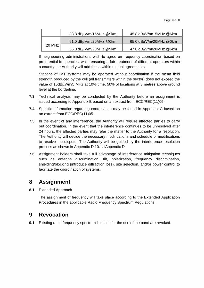
33.8 dBV/m/15MHz @9km 45.8 dBV/m/15MHz @6km
20 MHz 61.0 dBV/m/20MHz @0km 65.0 dBV/m/20MHz @0km
35.0 dBV/m/20MHz @9km 47.0 dBV/m/20MHz @6km
If neighbouring administrations wish to agree on frequency coordination based on preferential frequencies, while ensuring a fair treatment of different operators within a country the Authority will add these within mutual agreements.
Stations of IMT systems may be operated without coordination if the mean field strength produced by the cell (all transmitters within the sector) does not exceed the value of 15dBµV/m/5 MHz at 10% time, 50% of locations at 3 metres above ground level at the borderline

Page 12/190
7.3 Technical analysis may be conducted by the Authority before an assignment is issued according to Appendix B based on an extract from ECC/REC(11)05.
7.4 Specific information regarding coordination may be found in Appendix C an extract from ECC/REC(11)05.
7.5 In the event of any interference, the Authority will require affected parties to carry out coordination. In the event that the interference continues to be unresolved after 24 hours, the affected parties may refer the matter to the Authority for a resolution. The Authority will decide the necessary modifications and schedule of modifications to resolve the dispute. The Authority will be guided by the interference resolution process as shown in Appendix D.
7.6 Assignment holders shall take full advantage of interference mitigation techniques such as antenna discrimination, tilt, polarization, frequency discrimination, shielding/blocking (introduce diffraction loss), site selection, and/or power control to facilitate the coordination of systems.
8 Assignment 8.1 Extended Approach
The assignment of frequency will take place according to the Extended Application Procedures in the applicable Radio Frequency Spectrum Regulations.
9 Revocation 9.1 All radio frequency spectrum licences are revoked except for cases where there
coexistence with IMT is proven.
9.1.1 Existing radio frequency spectrum licences for the use of the band will be revoked as of 31st March 2018 for licensees operating in rural areas (except Transnet).
9.1.2 Existing radio frequency spectrum licences for the use of the band will be revoked as of 31st March 2022 for all remaining licensees.
9.2 In cases of coexistence, i.e. where a radio frequency spectrum licensee is able to migrate within the 450-470 MHz band and coexist with IMT, the radio frequency spectrum licence will be modified accordingly.
10 Radio Frequency Migration 10.1 Potential destination bands
The following graph describes the migration necessary to allocate the 450-470 MHz for IMT use.

Page 13/190
Figure 3: 450-470MHz potential destination spectrum
10.2 Migration Process:
Migration starts in 2016 and is completed in 2022.
Dual illumination stops in 2022.
SAPS - free up 406-426 MHz and migrate to 380-400 MHz:
Additional 2×3 MHz are still free for potential PPDR licences, e.g., emergency, airports (SAA).
Transnet - free up 450-470 MHz and potentially migrate to 406-426 MHz:
From 2016 Transnet can commence migration to 410-413//420-423MHz (2×3 MHz).
Alternatively there are 2×4 MHz and 2×3 MHz for TETRA available in 406-426 MHz.
Transnet may also migrate to the GSM R.
Other licensees - migrate from 450-470 MHz to:
403-406 MHz (unpaired);
426-430 MHz (unpaired) ;
440-450 MHz (paired or unpaired), potentially for municipality networks; and
In case of PPDR-use also to 387-390//397-400 MHz
430-440 MHz (amateurs) may be used in case of congestion for a defined period e.g. two years.
Meterological satelliteSAPS and PPDRDestination for TETRA servicesDestination for Transnet, et al.Destination bands for single frequency links, TelkomAmateursPotential extentions IMT450IMT450 options
Legend:
473
423
426
430
440
448
450
400
403
406
410
413
420
380

Page 14/190
Many municipality networks are in the 440-450 MHz bands. Depending on future demand, a harmonisation might take place.
In Figure 3 potential extensions to the IMT450-band are marked as well, in order mitigate potential interference with the direct neighbour bands. These might be reserved in case of extending 2×5 MHz to 2×10MHz or to minimize interference. Therefore these potential extension bands might be used only in congestion cases.- 448-450 MHz and 470-473 MHz (currently used by broadcaster) until the final IMT option and potential interferences are known.
10.3 Specific Procedure
Existing licensees must migrate according to the specified process.

Page 15/190
Appendix A National Radio Frequency Plan
ITU Region 1 allocation and footnotes
South African Allocation and footnotes
Typical Applications Comments
450-455 MHz
FIXED
MOBILE 5.286AA,
5.209, 5.271, 5.286, 5.286A, 5.286B, 5.286C,5.286D, 5.286E
400-455 MHz
FIXED
MOBILE 5.286AA, NF9
5.209, 5.286, 5.286A
Fixed links (450-453 MHz)
Single Frequency Mobile (453-454 MHz)
Paging (454-454.425MHz)
Trunked Mobile BTX (454.425-460 MHz)
IMT 450(450-470 MHz)
Paired with 460-463 MHz
Government Services
Paired with 464.425-470 MHz
455-456 MHz
FIXED
MOBILE 5.286AA
5.209, 5.271, 5.286A, 5.286B, 5.286C, 5.286E
455-456 MHz
FIXED
MOBILE (5.286AA, NF9
5.209, 5.286A
Trunked Mobile BTX (454.425-460MHz)
IMT 450(450-470 MHz)
Government Services
Paired with 464.425-470 MHz
456-459 MHz
FIXED
MOBILE 5.286AA
5.271, 5.287, 5.288
456-459 MHz
FIXED
MOBILE 5.286AA, NF9
5.287
Trunked Mobile BTX (454.425-460MHz)
IMT 450(450-470 MHz)
Government Services
Paired with 464.425-470 MHz
459-460 MHz
FIXED
459-460 MHz
FIXED

Page 16/190
MOBILE 5.286AA,
5.209, 5.271, 5.286A, 5.286B, 5.286C, 5.286E
MOBILE 5.286AA, NF9
5.209, 5.271, 5.286A
Trunked Mobile BTX (454.425 -460 MHz)
IMT 450(450-470 MHz)
Government Services
Paired with 464.425-470 MHz
460-470 MHz
FIXED
MOBILE 5.286AA
Meteorological satellite (space to Earth) 5.287, 5.288, 5.289, 5.290
460-470 MHz
FIXED
MOBILE 5.286AA, NF9
5.287, 5.289
Fixed links (460-463 MHz)
Single Frequency Mobile (463.025-463.975 MHz),
Low Power Mobile Radio(463.975 MHz, 464.125 MHz, 464.175 MHz, 464.325 MHz, 464.375 MHz)
Single Frequency Mobile (464.375-464.425 MHz)
Trunked Mobile MTX (464-470 MHz)
IMT 450(450-470 MHz);
Security Systems (464.5375 MHz)
Non specific SRDs (464.5-464.5875 MHz)
Government Services
Paired with 450-453 MHz;
Radio Frequency Spectrum Regulations Annex B GG No 34172, 31 March 2011)
Paired with 454.425-460 MHz
Radio Frequency Spectrum Regulations (Annex B (GG. No 34172, 31 March 2011)
Page 17/190
Appendix B Propagation Model
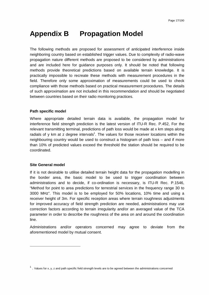
The following methods are proposed for assessment of anticipated interference inside neighboring country based on established trigger values. Due to complexity of radio-wave propagation nature different methods are proposed to be considered by administrations and are included here for guidance purposes only. It should be noted that following methods provide theoretical predictions based on available terrain knowledge. It is practically impossible to recreate these methods with measurement procedures in the field. Therefore only some approximation of measurements could be used to check compliance with those methods based on practical measurement procedures. The details of such approximation are not included in this recommendation and should be negotiated between countries based on their radio monitoring practices.
Path specific model
Where appropriate detailed terrain data is available, the propagation model for interference field strength prediction is the latest version of ITU-R Rec. P.452, For the relevant transmitting terminal, predictions of path loss would be made at x km steps along radials of y km at z degree intervals1. The values for those receiver locations within the neighbouring country would be used to construct a histogram of path loss – and if more than 10% of predicted values exceed the threshold the station should be required to be coordinated.
Site General model
If it is not desirable to utilise detailed terrain height data for the propagation modelling in the border area, the basic model to be used to trigger coordination between administrations and to decide, if co-ordination is necessary, is ITU-R Rec. P.1546, “Method for point to area predictions for terrestrial services in the frequency range 30 to 3000 MHz”. This model is to be employed for 50% locations, 10% time and using a receiver height of 3m. For specific reception areas where terrain roughness adjustments for improved accuracy of field strength prediction are needed, administrations may use correction factors according to terrain irregularity and/or an averaged value of the TCA parameter in order to describe the roughness of the area on and around the coordination line.
Administrations and/or operators concerned may agree to deviate from the aforementioned model by mutual consent.
1 . Values for x, y, z and path specific field strength levels are to be agreed between the administrations concerned

Page 18/190
Area calculations
In the case where greater accuracy is required, administrations and operators may use the area calculation below. For calculations, all the pixels of a given geographical area to be agreed between the Administrations concerned in a neighbouring country are taken into consideration. For the relevant base station, predictions of path loss should be made for all the pixels of a given geographical area from a base station and at a receiver antenna height of 3m above ground.
For evaluation,
• only 10 percent of the number of geographical area between the borderline (including also the borderline) and the 6 km line itself inside the neighbouring country may be interfered by higher field strength than the trigger field strength value given for the borderline in Annex 1 and 2 at a height of 3 m above ground.
• only 10 percent of the number of geographical area between the 6 km (including also 6km line) and 12 km line inside the neighbouring country may be interfered by higher field strength than the trigger field strength value given for the 6 km line in Annex 1 and 2 at a height of 3 m above ground.
It is recommended that during area calculations not only detailed terrain data but also clutter data be taken into account. Use of correction factors for clutter is crucial in particular where the border area is ‘open’ or ‘quasi-open’ from the point of view of clutter or where the interfering base station is just a few kilometres from a borderline.
If the distance between a base station and a terrain point of a borderline is closer than or equal to 1 km, free space propagation model needs to be applied. Furthermore, if there is no terrain obstacle within the 1st Fresnel zone, also the free space propagation model should be applied.
If clutter data is not available, it is proposed to extend the usage of free space propagation model to a few kilometres, depending on the clutter situation in border areas.
For area type interference calculations, propagation models with path specific terrain correction factors are recommended (e.g. Recommendation ITU–R P.1546 with the terrain clearance angle correction factor TCA, HCM method with the terrain clearance angle correction factor or Recommendation ITU–R P.1812).
As to correction factors for clutters ‘open area’ and ‘quasi-open area’, 20 dB and 15 dB should be used respectively. Recommendation ITU–R P.1406 should be used if a finer selection of clutter is required.
It must be noted that terrain irregularity factor Δh is not recommended to be used in area calculations. Administrations and/or operators concerned may agree to deviate from the aforementioned models by mutual consent.

Page 19/190
Appendix C Coordination for IMT-Systems
PREFERENTIAL PHYSICAL-LAYER CELL IDENTITIES (PCI) FOR IMT-2000/LTE2
The following is extracted from ECC/REC(11)05 as an operational example and can be adapted for the SADC-countries
PCI co-ordination is only needed when channel centre frequencies are aligned independent of the channel bandwidth.
3GPP TS 36.211 defines 168 “unique physical-layer cell-identity groups” in §6.11, numbered 0…167, hereafter called “PCI groups”. Within each PCI group there are three separate PCIs giving 504 PCIs in total.
Administrations should agree on a repartition of these 504 PCI on an equitable basis when channel centre frequencies are aligned as shown in the Table below. It has to be noted that dividing the PCI groups or PCI’s is equivalent. Each country can use all PCI groups away from the border areas.
As shown in the table below, the PCI’s should be divided into 6 sub-sets containing each one sixth of the available PCI’s. Each country is allocated three sets (half of the PCI’s) in a bilateral case, and two sets (one third of the PCI’s) in a trilateral case.
Four types of countries are defined in a way such that no country will use the same code set as any one of its neighbours. The following lists describe the distribution of European countries (which needs to be adapted for SADC):
Type country 1: BEL, CVA, CYP, CZE, DNK, E, FIN, GRC, IRL, ISL, LTU, MCO, SMR, SUI, SVN, UKR, AZE, SRB.
Type country 2: AND, BIH, BLR, BUL, D, EST, G, HNG, I, MDA, RUS (Exclave), GEO
Type country 3: ALB, AUT, F, HOL, HRV, POL, POR, ROU, RUS, S, MLT
Type country 4:LIE, LUX, LVA, MKD, MNE, NOR, SVK, TUR.
For each type of country, the following tables and figure describe the sharing of the PCI’s with its neighbouring countries, with the following conventions of writing:
Preferential PCI
non-preferential PCI
2 ECC/REC(11)05

Page 20/190
The 504 physical-layer cell-identities should be divided into the following 6 sub-sets when the carrier frequencies are aligned in border areas:
PCI Set A
Set B Set C Set D Set E Set F PCI
Set A Set B Set C Set D Set E Set F
Country 1 0..83
84..167 168..251 252..335
336..419 420..503 Country 2 0..83
84..16
7 168..25
1 252..335
336..4
19 420..503
Border 1-2 Border 2-1
Zone 1-2-3 Zone 2-3-1
Border 1-3 Border 2-3
Zone 1-2-4 Zone 2-1-4
Border 1-4 Border 2-4
Zone 1-3-4 Zone 2-3-4
PCI Set A Set B Set C Set D Set E Set F PCI
Set A Set B Set C Set D Set E Set F
Country 3 0..83
84..167 168..251 252..335
336..419 420..503 Country 4 0..83
84..16
7 168..25
1 252..335
336..4
19 420..503
Border 3-2 Border 4-1
Zone 3-1-2 Zone 4-1-2
Border 3-1 Border 4-2
Zone 3-1-4 Zone 4-2-3
Border 3-4 Border 4-3
Zone 3-2-4 Zone 4-3-1
Notes 1) All PCI’s are available in areas away from the border. 2) In certain specific cases (e.g. AUT/HRV) where the distance between two countries of the same type number is very small (< few 10s km), it may be necessary to address the situation in bi/multilateral coordination agreements as necessary, and may include further subdivision of the allocated codes in certain areas.

Page 21/190
GUIDANCE ON THE CONSIDERATION OF LTE RADIO PARAMETERS FOR USE IN BILATERAL AND MULTI LATERAL AGREEMENTS
This Annex is provided for guidance purposes for use in bi-lateral and multilateral discussions. For LTE, it may be beneficial to coordinate other radio parameters besides PCI in order to minimise deteriorating effects of uplink interference.
The parameters described in this Annex are usually optimised during LTE radio network planning of an operator’s network. The idea of optimisation is to plan the parameters taking into account specific correlation properties of the uplink control signals which enable more stable and predictable operation of the network. In the cross-border scenario the optimisation of parameters among neighbouring operators could provide better control of uplink interference. However because of the difference between intra-network and inter-network interference and due to limited experience in the LTE cross-border deployment it is difficult to assess the benefits of such optimisation. The following guidance provides the basis for operators to consider in border areas in case of high levels of uplink interference.
1. Demodulation Reference Signal (DM RS) coordination
Demodulation reference signals (DM RS) are transmitted in the uplink and used for channel estimation. There is a risk of intercell interference between neighbouring cells even in case of no frame synchronisation. That is why special measures for DM RS allocation between networks in neighbouring countries occupying the same channel may need to be applied. The case of partial channel overlap has not been studied but due to DM RS occupying resource blocks of separate users there is a risk of DM RS collisions between neighbouring networks when the subcarriers positions coincide (the frequency offset between central carriers of neighbouring networks is multiple of 300 kHz). Some minor benefits from DM RS coordination in these particular cases could be expected.
There are a number of possible approaches to the coordination of DM RS:
In basic planning procedure only 30 DM RS sequence groups with favourable correlation characteristics are available: {0…29}. In this case each cell could be assigned one of the 30 DM RS sequence groups providing cluster size of 30.
It is possible to extend each DM RS sequence group to generate up to 12 time shifted sequence groups by applying the cyclic shift parameter stated in 3GPP TS 36.211. For example each tri-sector site could be assigned one DM RS sequence group with each co-sited cell having its own cyclic shift of 2π/3 which provides cluster size 30 only with 10 DM RS sequence groups. The latter case corresponds well to the case of DM RS sequence groups repartition between neighbouring countries when only limited number of groups is available for network planning. The drawback of DM RS sequence group cyclic shift is a loss of orthogonally of DM RS due to fading channels which has been found only recently during first trials of LTE and caused throughput loss as well as time alignment problems.
Another approach for DM RS coordination is to implement dynamic DM RS sequence group allocation also called pseudo-random group hopping. In this method nearby

Page 22/190
cells are grouped into clusters up to 30 cells and within each cell cluster the same hopping-pattern is used. At the border of two clusters inter-cell interference is averaged since two different hopping patterns are utilised. There are 17 defined hopping patterns, numbered {0…16}, which leads to some minor unfairness in case of apportioning these patterns between neighbouring countries. Even in a trilateral case each operator will have at least 5 hopping patterns available near the border which should be enough for planning purposes. It should be noted the pseudo-random group hopping option could be absent in the first generations of LTE equipment.
The decision of which of these methods to use in cross-border coordination should be agreed upon by the interested parties. Specific DM RS sequence groups or hopping patterns repartition is not provided in the text of this Recommendation but could be deduced in a similar manner to the PCI repartition.
2. Physical Random Access Channel (PRACH) coordination
Another radio network parameter which is considered during radio network planning is PRACH configuration which is needed to distinguish random access requests addressed to different cells. PRACH resources are allocated by specifying the PRACH Resource Blocks time positions within the uplink frame, their frequency position within the LTE channel bandwidth and by apportioning cell-specific root sequences. During radio network planning these parameters are usually used in the following way:
time positions for PRACH resource allocations are usually used to create time collision of PRACH resources of co-sited/frame synchronised cells because PRACH-to-PRACH interference is usually less severe than PUSCH-to-PRACH interference;
frequency positions within the LTE channel bandwidth is usually the same for all cells, again because PRACH-to-PRACH interference case is more favourable one.
cell-specific root sequences are used to distinguish between PRACH requests addressed to different cells.
For cross-border coordination it is proposed to use frequency position offsets to exclude the possibility of so-called “ghost” PRACH requests caused by neighbouring networks. The PRACH is configured in LTE to use only 6 Resource Blocks or 1.08 MHz of the LTE channel bandwidth except in regions used by PUCCH. In case of overlapping or partially overlapping channel bandwidths of neighbouring networks it is enough to establish non-overlapping PRACH frequency blocks to perform coordination. Because it is difficult to establish an implementation dependent procedure for such allocation it will be the responsibility of operators to manage such frequency separation during coordination discussions.
In early implementation it is possible that very limited number of frequency positions will be supported by LTE equipment which will not be enough to coordinate in the trilateral case. In such cases root-sequence repartition could be used. There are 838 root sequences in total to be distributed between cells, numbered {0..837}. There are two numbering schemes for PRACH root sequences (physical and logical) and that only logical root sequences numbering needs be used for coordination. Unfortunately the

Page 23/190
process of root sequences planning doesn’t involve direct mapping of root sequences between cells because the number of root sequences needed for one cell is dependent on the cell range. The table showing such interdependency is presented below:
PRACH Configuration Number of root seq. per cell Cell Range (km)
1 1 0.7
2 2 1
3 2 1.4
4 2 2
5 2 2.5
6 3 3.4
7 3 4.3
8 4 5.4
9 5 7.3
10 6 9.7
11 8 12.1
12 10 15.8
13 13 22.7
14 22 38.7
15 32 58.7
0 64 118.8
Thus in the case of root sequence reparation it will be the responsibility of radio network planners to assign the correct number of root sequences in order to not to overlap with the root sequence ranges of other operators. It also should be noted that different root sequences have different cubic metrics and correlation properties which affect PRACH coverage performance and planning of so-called high-speed cells. For simplicity of cross-border coordination it is proposed to ignore these properties.
In summary it should be stipulated that frequency separation of PRACH resources should be used as the main coordination method. PRACH root sequences repartition should be avoided and used only in exceptional cases. Specific PRACH root sequences repartition is not provided in the text of this Recommendation but could be deduced in a similar manner to the PCI repartition.

Page 24/190
Appendix D Interference Resolution Process
When requesting coordination the relevant characteristics of the base station and the code or PCI group number should be forwarded to the Administration affected. All of the following characteristics should be included:
a) carrier frequency [MHz]
b) name of transmitter station
c) country of location of transmitter station
d) geographical coordinates [latitude, longitude]
e) effective antenna height [m]
f) antenna polarisation
g) antenna azimuth [deg]
h) antenna gain [dBi]
i) effective radiated power [dBW]
j) expected coverage zone or radius [km]
k) date of entry into service [month, year].
l) code group number used
m) antenna tilt [deg]
The Administration affected shall evaluate the request for coordination and shall within 30 days notify the result of the evaluation to the Administration requesting coordination. If in the course of the coordination procedure the Administration affected requires additional information, it may request such information.
If in the course of the coordination procedure an Administration may request additional information.
If no reply is received by the Administration requesting coordination within 30 days it may send a reminder to the Administration affected. An Administration not having responded within 30 days following communication of the reminder shall be deemed to have given its consent and the code co-ordination may be put into use with the characteristics given in the request for coordination.
The periods mentioned above may be extended by common consent.

Page 1/190
Government Gazette
GENERAL NOTICE
NOTICE 1011 OF 2014
INDEPENDENT COMMUNICATIONS AUTHORITY OF SOUTH AFRICA
PURSUANT TO SECTION 4 (1) OF THE ELECTRONIC COMMUNICATIONS ACT 2005, (ACT NO. 36 OF 2005)
HEREBY ISSUES A NOTICE REGARDING THE DRAFT RADIO FREQUENCY SPECTRUM ASSIGNMENT PLAN FOR THE FREQUENCY BAND 703 TO 733 MHz AND 758 TO 788 MHz FOR CONSULTATION.
1. The Independent Communications Authority of South Africa ("the Authority"), hereby publishes Draft Radio Frequency Spectrum Assignment Plan for the frequency band 703 to 733 MHz and 758 to 788 MHz for consultation in terms of sections 2 (d), (e) and 4, read with sections 30, 31(4), and 33 of the Electronic Communications Act (Act No. 36 of 2005) and read with Regulation 3 of the Radio Frequency Spectrum Regulations 2011 and read with the IMT Roadmap 2014.
2. This Radio Frequency Spectrum Assignment Plan supersedes any previous spectrum assignment arrangements for the same spectrum location.
3. Interested persons are hereby invited to submit written representations, including an electronic version of the representation in Microsoft Word, of their views on the Draft Radio Frequency Spectrum Assignment Plan for the frequency band 703 to

Page 2/190
733 MHz and 758 to 788 MHz by no later than 16h00 on Friday 28th November 2014.
4. Written representations or enquiries may be directed to:
The Independent Communications Authority of South Africa (ICASA)
Pinmill Farm Block A
164 Katherine Street
South Africa
or
Private Bag XI0002
Sandton
2146
Attention:
Mr Manyaapelo Richard Makgotlho
e-mail: [email protected]
5. All written representations submitted to the Authority pursuant to this notice shall be made available for inspection by interested persons from 2nd December 2014 at the ICASA Library or website and copies of such representations and documents will be obtainable on payment of a fee.
Where persons making representations require that their representation, or part thereof, be treated confidentially, then an applications in terms of section 4D of the ICASA Act, 2000 (Act No. 13 of 2000) must be lodged with the Authority. Such an application must be submitted simultaneously with the representation on the draft regulations and plan. Respondents are requested to separate any confidential material into a clearly marked confidential annexure. If, however, the request for confidentiality is refused, the person making the request will be allowed to withdraw the representation or document in question.
_______________ Dr SS MNCUBE CHAIRPERSON

Page 3/190
Radio Frequency Spectrum Assignment Plan
Rules for Services operating in the Frequency Band
from 703 to 733 MHz and 758 to 788 MHz
(IMT700)

Page 4/190
Table of Contents
1 Glossary ............................................................................................. 5
2 Purpose .............................................................................................. 6
3 General ............................................................................................... 6
4 Channelling Plan ................................................................................ 7
5 Requirements for usage of radio frequency spectrum ................... 8
6 Implementation .................................................................................. 9
7 Co-ordination Requirements ............................................................. 9
8 Assignment ...................................................................................... 10
9 Revocation ....................................................................................... 10
10 Radio Frequency Migration ............................................................. 11
Appendix A National Radio Frequency Plan ............................................... 12
Appendix B Propagation Model.................................................................... 14
Appendix C Coordination for IMT-Systems ................................................. 16
Appendix D Interference Resolution Process ............................................. 21

Page 5/190
1 Glossary
In this Radio Frequency Spectrum Assignment Plan, terms used shall have the same meaning as in the Electronic Communications Act 2005 (no. 36 of 2005); unless the context indicates otherwise:
“3GPP” means the 3rd Generation Partnership Project (3GPP) which consists of six telecommunications standard development organisations
“Act” means the Electronic Communications Act, 2005 (Act No. 36 of 2005) as amended
“DM RS” means Demodulation Reference Signal
“ECC/REC(11)04” means ECC Recommendation (11)04
“ECC” means Electronic Communications Committee within the European Conference of Postal and Telecommunications Administrations (CEPT)
“FDD” means Frequency Division Duplex
“HCM” means harmonised calculation method
“IMT” means International Mobile Telecommunications
“IMT700” means IMT in the 700MHz band
“ITA” means Invitation to Apply
“ITU” means the International Telecommunication Union
“ITU-R” means the International Telecommunication Union Radiocommunication Sector
“LTE” means Long Term Evolution is a standard for wireless communication of high-speed data for mobile phones and data terminals. It is based on the GSM/EDGE and UMTS/HSPA network technologies
“NRFP” means the National Radio Frequency Plan 2013 for South Africa
“PCI” means Physical-Layer Cell Identities
“PRACH” means Physical Random Access Channel
“PSTN” means public switched telephone network
“PUCCH” means Physical Uplink Control Channel
“RFSAP” means Radio Frequency Spectrum Assignment Plan
“TCA” means terrain clearance angle

Page 6/190
“TDD” means Time Division Duplex
“WRC-12” means World Radio Conference 2012 held in Geneva
“WRC-15” means the World Radio Conference planned to be held in 2015
2 Purpose 2.1 A Radio Frequency Spectrum Assignment Plan (RFSAP) provides information on
the requirements attached to the use of a frequency band in line with the allocation and other information in the National Radio Frequency Plan (NRFP). This information includes technical characteristics of radio systems, frequency channelling, coordination and details on required migration of existing users of the band and the expected method of assignment.
2.2 This Frequency Assignment Plan states the requirements for the utilization of the frequency band between 703-733 MHz paired with 758-788 MHz for IMT700.
2.3 The ITU states that International Mobile Telecommunications (IMT) systems are mobile systems that provide access to a wide range of telecommunication services including advanced mobile services, supported by mobile and fixed networks, which are increasingly packet-based.
Key features:
a high degree of commonality of functionality worldwide while retaining the flexibility to support a wide range of services and applications in a cost efficient manner
compatibility of services within IMT and with fixed networks
capability of interworking with other radio access systems
high quality mobile services
user equipment suitable for worldwide use
user-friendly applications, services and equipment
worldwide roaming capability
enhanced peak data rates to support advanced services and applications
3 General 3.1 Technical characteristics of equipment used in IMT700 systems shall conform to all
applicable South African standards, international standards, International Telecommunications Union (ITU) and its radio regulations as agreed and adopted by South Africa.
3.2 All installations must comply with safety rules as specified in applicable standards.
3.3 The equipment used shall be certified under South African law and regulations.

Page 7/190
3.4 The allocation of this frequency band and the information in this Radio Frequency Spectrum Assignment Plan (RFSAP) are subject to review.
3.5 Frequency bands assigned for IMT700 include bands between 703-733 MHz paired with 758-788 MHz.
3.6 Likely use of this band will be for Mobile voice and data communications.
3.7 The technologies which can provide IMT700 services include, but are not limited to:
LTE,
LTE Advanced,
HSPA+,
WiMAX
3.8 Typical technical and operational characteristics of IMT systems as identified as by the ITU are described in the following documents:
Recommendation ITU-R M.2012-1 (02/2014): Detailed specifications of the terrestrial radio interfaces of International Mobile Telecommunications-Advanced (IMT Advanced).
Report ITU-R2241-0 Compatibility studies in relation to Resolution 224 in the bands 698-806 MHz and 790-862 MHz.
Report ITU-R M.2074: Report on Radio Aspects for the terrestrial component of IMT-2000 and systems beyond IMT-2000.
Recommendation ITU-R M.1645 Framework and overall objectives of the future development of IMT-2000 and systems beyond IMT-2000.
Recommendation ITU-R M.1036-4: Frequency arrangements for implementation of the terrestrial component of International Mobile Telecommunications (IMT) in the bands identified for IMT in the Radio Regulations (RR).
4 Channelling Plan 4.1 The frequency band 703-733 MHz paired with 758-788 MHz provides a total
bandwidth of
2×30MHz FDD and for IMT700
25MHz of spectrum remain in the centre gap between the FDD uplink and downlink (i.e. 733-758MHz or the IMT750 band).

Page 8/190
4.2 Channel arrangements for the IMT700 band are according to the Region 1 recommendation by the ITU.
Figure 4: Channel arrangements for IMT700
5 Requirements for usage of radio frequency spectrum 5.1 This chapter covers the minimum key characteristics considered necessary in order
to make the best use of the available frequencies.
5.2 The use of the band is limited for IMT-services.
5.3 Only systems using digital technologies that promote spectral efficiency will be issued with an assignment. Capacity enhancing digital techniques is being rapidly developed and such techniques that promote efficient use of spectrum, without reducing quality of service are encouraged.
5.4 In some cases, a radio system conforming to the requirements of this RFSAP may require modifications if harmful interference is caused to other radio stations or systems.
5.5 The allocation of spectrum and shared services within these bands are found in the National Radio Frequency Plan (NRFP) and an extract of NRFP is shown in Appendix A.
5.6 Maximum radiated power:
5.6.1 Base Station transmissions should not exceed 61dBm/5MHz EIRP.
5.6.2 Mobile Station transmissions should not exceed 23dBm EIRP.
5.6.3 On a case to case basis, higher EIRP may be permitted if acceptable technical justification is provided.
5.6.4 Where appropriate subscriber terminal station should comply with the technical specification outlined under “3GPP TS 36.521-1”.
5.7 In some cases, a radio system conforming to the requirements of this RFSAP may require modifications if major interference is caused to other radio stations or systems.
5.8 Criteria and guidelines for interference mitigation are described in Appendix D.
Uplink Downlink Centre gap
Legend
788
703
733
758

Page 9/190
6 Implementation 6.1 This Radio Frequency Assignment Plan comes into effect on the 1st January 2016.
6.2 The process of assignment may commence prior to the date referred to in section 6.1.
6.3 No new assignment for IMT700 in the band 703-733 MHz paired with 758-788 MHz. shall be approved unless they comply with this RFSAP.
7 Co-ordination Requirements 7.1 Use of these frequency bands shall require coordination with the neighbouring
countries within the coordination zones of 6 kilometres in case of LTE-to-LTE or 9 kilometres in case of LTE-to-other technologies from the neighbouring country. The coordination distance is continuously being reviewed and may be updated from time to time.
7.2 The following field strength thresholds have to be assured based on (ECC/REC(11)04 for 790-862MHz also taken here for 703-790MHz). Operator-to-operator coordination may be necessary to avoid interference
In general stations of FDD systems may be used without coordination with a neighbouring country if the mean field strength produced by the cell (all transmitters within the sector) does not exceed the value of 55dBV/m/5MHz at a height of 3m above ground at the borderline between countries and does not exceed a value of 29dBV/m/5MHz at a height of 3m above ground at a distance of 9 km inside the neighbouring country.
In the case that LTE is deployed both sides of the border the field strength levels can be increased to 59 dBV/m/5MHz and 41 dBV/m/5MHz at 6 km.
If TDD is in operation across both sides of a border and is synchronised across the border then field strength levels as well.
For field strength predictions the calculations should be made according to Appendix B. In cases of other frequency block sizes 10*log (frequency block size/5MHz) should be added to the field strength values e.g.:
BW (MHz)
Field strength level at 3 m height
(general case)
Field strength level at 3 m height
(LTE case)
5 MHz 55.0 dBV/m/5MHz @0km 59.0 dBV/m/5MHz @0km
29.0 dBV/m/5MHz @9km 41.0 dBV/m/5MHz @6km
10 MHz 58.0 dBV/m/10MHz @0km 62.0 dBV/m/10MHz @0km
32.0 dBV/m/10MHz @9km 44.0 dBV/m/10MHz @6km
15 MHz 59.8 dBV/m/15MHz @0km 63.8 dBV/m/15MHz @0km
Page 10/190
33.8 dBV/m/15MHz @9km 45.8 dBV/m/15MHz @6km
20 MHz 61.0 dBV/m/20MHz @0km 65.0 dBV/m/20MHz @0km
35.0 dBV/m/20MHz @9km 47.0 dBV/m/20MHz @6km
If neighbouring administrations wish to agree on frequency coordination based on preferential frequencies, while ensuring a fair treatment of different operators within a country the Authority will add these within mutual agreements.
Stations of IMT systems may be operated without coordination if the mean field strength produced by the cell (all transmitters within the sector) does not exceed the value of 15dBµV/m/5 MHz at 10% time, 50% of locations at 3 metres above ground level at the borderline.
7.3 Technical analysis may be conducted by the Authority before an assignment is issued according to Appendix B based on an extract from ECC/REC(11)05.
7.4 Specific information regarding coordination may be found in Appendix C based on an extract from ECC/REC(11)05.
7.5 In the event of any interference, the Authority will require affected parties to carry out coordination. In the event that the interference continues to be unresolved after 24 hours, the affected parties may refer the matter to the Authority for a resolution. The Authority will decide the necessary modifications and schedule of modifications to resolve the dispute. The Authority will be guided by the interference resolution process as shown in Appendix D.10.1.1Appendix D
7.6 Assignment holders shall take full advantage of interference mitigation techniques such as antenna discrimination, tilt, polarization, frequency discrimination, shielding/blocking (introduce diffraction loss), site selection, and/or power control to facilitate the coordination of systems.
8 Assignment 8.1 Extended Approach
The assignment of frequency will take place according to the Extended Application Procedures in the applicable Radio Frequency Spectrum Regulations.
9 Revocation 9.1 Existing radio frequency spectrum licences for the use of the band are revoked.
Page 11/190
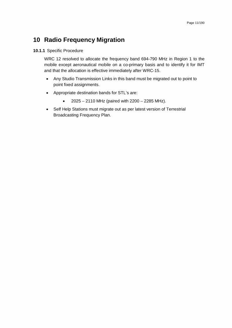
10 Radio Frequency Migration 10.1.1 Specific Procedure
WRC 12 resolved to allocate the frequency band 694-790 MHz in Region 1 to the mobile except aeronautical mobile on a co-primary basis and to identify it for IMT and that the allocation is effective immediately after WRC-15.
Any Studio Transmission Links in this band must be migrated out to point to point fixed assignments.
Appropriate destination bands for STL’s are:
2025 – 2110 MHz (paired with 2200 – 2285 MHz).
Self Help Stations must migrate out as per latest version of Terrestrial Broadcasting Frequency Plan.

Page 12/190
Appendix A National Radio Frequency Plan
ITU Region 1 allocations and footnote
South African allocations and footnotes
Typical Applications Comments
470-790MHz(694-790)
BROADCASTING
5.149 5.291A 5.294 5.296 5.300 5.304 5.306 5.311A 5.312 5.312A
470-790 MHz
BROADCASTING
RADIO ASTRONOMY
MOBILE except aeronautical mobile NF9
5.149 5.311A 5.312A
Television Broadcasting (470 – 854 MHz)
Radio Astronomy (606-614 MHz)
IMT700 (694-790 MHz)
Broadcasting Allotments in accordance with GE89 plan in the process of conversion to GE06. Broadcast assignments in accordance with the latest version of the Terrestrial Broadcasting Frequency Plan. The use of ‘White Spaces’ in this band is under consideration (subject to NINP basis to users under a primary allocation.)
790-862 MHz
FIXED
MOBILE except aeronautical mobile 5.317A
790-862 MHz
FIXED
MOBILE except aeronautical mobile 5.316B 5.317A NF9
Fixed Links (856 – 864.1 MHz)
IMT800 BTX (791 – 821 MHz)
The fixed links will be migrated along with the broadcasting service in line with Radio Frequency Migration Plan.
Paired with 832 – 862 MHz

Page 13/190
BROADCASTING
5.312 5.314 5.315 5.316 5.316A 5.319
BROADCASTING
5.316A
Mobile Wireless Access (827.775 – 832.695 MHz)
IMT800 MTX (832. 695 – 862 MHz)
Television Broadcasting (470 – 854 MHz)
Paired with Access (872.775 – 877.695 MHz)
Paired with 791 – 821 MHz
Broadcasting Allotments in accordance with GE89 plan in the process of conversion to GE06. Broadcast assignments in accordance with the latest version of the Terrestrial Broadcasting Frequency Plan.

Page 14/190
Appendix B Propagation Model
The following methods are proposed for assessment of anticipated interference inside neighboring country based on established trigger values. Due to complexity of radio-wave propagation nature different methods are proposed to be considered by administrations and are included here for guidance purposes only. It should be noted that following methods provide theoretical predictions based on available terrain knowledge. It is practically impossible to recreate these methods with measurement procedures in the field. Therefore only some approximation of measurements could be used to check compliance with those methods based on practical measurement procedures. The details of such approximation are not included in this recommendation and should be negotiated between countries based on their radio monitoring practices.
Path specific model
Where appropriate detailed terrain data is available, the propagation model for interference field strength prediction is the latest version of ITU-R Rec. P.452, For the relevant transmitting terminal, predictions of path loss would be made at x km steps along radials of y km at z degree intervals3. The values for those receiver locations within the neighbouring country would be used to construct a histogram of path loss – and if more than 10% of predicted values exceed the threshold the station should be required to be coordinated.
Site General model
If it is not desirable to utilise detailed terrain height data for the propagation modelling in the border area, the basic model to be used to trigger coordination between administrations and to decide, if co-ordination is necessary, is ITU-R Rec. P.1546, “Method for point to area predictions for terrestrial services in the frequency range 30 to 3000 MHz”. This model is to be employed for 50% locations, 10% time and using a receiver height of 3m. For specific reception areas where terrain roughness adjustments for improved accuracy of field strength prediction are needed, administrations may use correction factors according to terrain irregularity and/or an averaged value of the TCA parameter in order to describe the roughness of the area on and around the coordination line.
Administrations and/or operators concerned may agree to deviate from the aforementioned model by mutual consent.
3 . Values for x, y, z and path specific field strength levels are to be agreed between the administrations concerned

Page 15/190
Area calculations
In the case where greater accuracy is required, administrations and operators may use the area calculation below. For calculations, all the pixels of a given geographical area to be agreed between the Administrations concerned in a neighbouring country are taken into consideration. For the relevant base station, predictions of path loss should be made for all the pixels of a given geographical area from a base station and at a receiver antenna height of 3m above ground.
For evaluation,
• only 10 percent of the number of geographical area between the borderline (including also the borderline) and the 6 km line itself inside the neighbouring country may be interfered by higher field strength than the trigger field strength value given for the borderline in Annex 1 and 2 at a height of 3 m above ground.
• only 10 percent of the number of geographical area between the 6 km (including also 6km line) and 12 km line inside the neighbouring country may be interfered by higher field strength than the trigger field strength value given for the 6 km line in Annex 1 and 2 at a height of 3 m above ground.
It is recommended that during area calculations not only detailed terrain data but also clutter data be taken into account. Use of correction factors for clutter is crucial in particular where the border area is ‘open’ or ‘quasi-open’ from the point of view of clutter or where the interfering base station is just a few kilometres from a borderline.
If the distance between a base station and a terrain point of a borderline is closer than or equal to 1 km, free space propagation model needs to be applied. Furthermore, if there is no terrain obstacle within the 1st Fresnel zone, also the free space propagation model should be applied.
If clutter data is not available, it is proposed to extend the usage of free space propagation model to a few kilometres, depending on the clutter situation in border areas.
For area type interference calculations, propagation models with path specific terrain correction factors are recommended (e.g. Recommendation ITU–R P.1546 with the terrain clearance angle correction factor TCA, HCM method with the terrain clearance angle correction factor or Recommendation ITU–R P.1812).
As to correction factors for clutters ‘open area’ and ‘quasi-open area’, 20 dB and 15 dB should be used respectively. Recommendation ITU–R P.1406 should be used if a finer selection of clutter is required.
It must be noted that terrain irregularity factor Δh is not recommended to be used in area calculations. Administrations and/or operators concerned may agree to deviate from the aforementioned models by mutual consent.

Page 16/190
Appendix C Coordination for IMT-Systems
PREFERENTIAL PHYSICAL-LAYER CELL IDENTITIES (PCI) FOR IMT-2000/LTE4
The following is extracted from ECC/REC(11)05 as an operational example and can be adapted for the SADC-countries
PCI co-ordination is only needed when channel centre frequencies are aligned independent of the channel bandwidth.
3GPP TS 36.211 defines 168 “unique physical-layer cell-identity groups” in §6.11, numbered 0…167, hereafter called “PCI groups”. Within each PCI group there are three separate PCIs giving 504 PCIs in total.
Administrations should agree on a repartition of these 504 PCI on an equitable basis when channel centre frequencies are aligned as shown in the Table below. It has to be noted that dividing the PCI groups or PCI’s is equivalent. Each country can use all PCI groups away from the border areas.
As shown in the table below, the PCI’s should be divided into 6 sub-sets containing each one sixth of the available PCI’s. Each country is allocated three sets (half of the PCI’s) in a bilateral case, and two sets (one third of the PCI’s) in a trilateral case.
Four types of countries are defined in a way such that no country will use the same code set as any one of its neighbours. The following lists describe the distribution of European countries (which needs to be adapted for SADC):
Type country 1: BEL, CVA, CYP, CZE, DNK, E, FIN, GRC, IRL, ISL, LTU, MCO, SMR, SUI, SVN, UKR, AZE, SRB.
Type country 2: AND, BIH, BLR, BUL, D, EST, G, HNG, I, MDA, RUS (Exclave), GEO
Type country 3: ALB, AUT, F, HOL, HRV, POL, POR, ROU, RUS, S, MLT
Type country 4:LIE, LUX, LVA, MKD, MNE, NOR, SVK, TUR.
For each type of country, the following tables and figure describe the sharing of the PCI’s with its neighbouring countries, with the following conventions of writing:
Preferential PCI
non-preferential PCI
4 ECC/REC(11)05

Page 17/190
The 504 physical-layer cell-identities should be divided into the following 6 sub-sets when the carrier frequencies are aligned in border areas:
PCI Set A
Set B Set C Set D Set E Set F PCI
Set A Set B Set C Set D Set E Set F
Country 1 0..83
84..167 168..251 252..335
336..419 420..503 Country 2 0..83
84..16
7 168..25
1 252..335
336..4
19 420..503
Border 1-2 Border 2-1
Zone 1-2-3 Zone 2-3-1
Border 1-3 Border 2-3
Zone 1-2-4 Zone 2-1-4
Border 1-4 Border 2-4
Zone 1-3-4 Zone 2-3-4
PCI Set A Set B Set C Set D Set E Set F PCI
Set A Set B Set C Set D Set E Set F
Country 3 0..83
84..167 168..251 252..335
336..419 420..503 Country 4 0..83
84..16
7 168..25
1 252..335
336..4
19 420..503
Border 3-2 Border 4-1
Zone 3-1-2 Zone 4-1-2
Border 3-1 Border 4-2
Zone 3-1-4 Zone 4-2-3
Border 3-4 Border 4-3
Zone 3-2-4 Zone 4-3-1
Notes 1) All PCI’s are available in areas away from the border. 2) In certain specific cases (e.g. AUT/HRV) where the distance between two countries of the same type number is very small (< few 10s km), it may be necessary to address the situation in bi/multilateral coordination agreements as necessary, and may include further subdivision of the allocated codes in certain areas.

Page 18/190
GUIDANCE ON THE CONSIDERATION OF LTE RADIO PARAMETERS FOR USE IN BILATERAL AND MULTI LATERAL AGREEMENTS
This Annex is provided for guidance purposes for use in bi-lateral and multilateral discussions. For LTE, it may be beneficial to coordinate other radio parameters besides PCI in order to minimise deteriorating effects of uplink interference.
The parameters described in this Annex are usually optimised during LTE radio network planning of an operator’s network. The idea of optimisation is to plan the parameters taking into account specific correlation properties of the uplink control signals which enable more stable and predictable operation of the network. In the cross-border scenario the optimisation of parameters among neighbouring operators could provide better control of uplink interference. However because of the difference between intra-network and inter-network interference and due to limited experience in the LTE cross-border deployment it is difficult to assess the benefits of such optimisation. The following guidance provides the basis for operators to consider in border areas in case of high levels of uplink interference.
1. Demodulation Reference Signal (DM RS) coordination
Demodulation reference signals (DM RS) are transmitted in the uplink and used for channel estimation. There is a risk of intercell interference between neighbouring cells even in case of no frame synchronisation. That is why special measures for DM RS allocation between networks in neighbouring countries occupying the same channel may need to be applied. The case of partial channel overlap has not been studied but due to DM RS occupying resource blocks of separate users there is a risk of DM RS collisions between neighbouring networks when the subcarriers positions coincide (the frequency offset between central carriers of neighbouring networks is multiple of 300 kHz). Some minor benefits from DM RS coordination in these particular cases could be expected.
There are a number of possible approaches to the coordination of DM RS:
In basic planning procedure only 30 DM RS sequence groups with favourable correlation characteristics are available: {0…29}. In this case each cell could be assigned one of the 30 DM RS sequence groups providing cluster size of 30.
It is possible to extend each DM RS sequence group to generate up to 12 time shifted sequence groups by applying the cyclic shift parameter stated in 3GPP TS 36.211. For example each tri-sector site could be assigned one DM RS sequence group with each co-sited cell having its own cyclic shift of 2π/3 which provides cluster size 30 only with 10 DM RS sequence groups. The latter case corresponds well to the case of DM RS sequence groups repartition between neighbouring countries when only limited number of groups is available for network planning. The drawback of DM RS sequence group cyclic shift is a loss of orthogonally of DM RS due to fading channels which has been found only recently during first trials of LTE and caused throughput loss as well as time alignment problems.
Another approach for DM RS coordination is to implement dynamic DM RS sequence group allocation also called pseudo-random group hopping. In this method nearby

Page 19/190
cells are grouped into clusters up to 30 cells and within each cell cluster the same hopping-pattern is used. At the border of two clusters inter-cell interference is averaged since two different hopping patterns are utilised. There are 17 defined hopping patterns, numbered {0…16}, which leads to some minor unfairness in case of apportioning these patterns between neighbouring countries. Even in a trilateral case each operator will have at least 5 hopping patterns available near the border which should be enough for planning purposes. It should be noted the pseudo-random group hopping option could be absent in the first generations of LTE equipment.
The decision of which of these methods to use in cross-border coordination should be agreed upon by the interested parties. Specific DM RS sequence groups or hopping patterns repartition is not provided in the text of this Recommendation but could be deduced in a similar manner to the PCI repartition.
2. Physical Random Access Channel (PRACH) coordination
Another radio network parameter which is considered during radio network planning is PRACH configuration which is needed to distinguish random access requests addressed to different cells. PRACH resources are allocated by specifying the PRACH Resource Blocks time positions within the uplink frame, their frequency position within the LTE channel bandwidth and by apportioning cell-specific root sequences. During radio network planning these parameters are usually used in the following way:
time positions for PRACH resource allocations are usually used to create time collision of PRACH resources of co-sited/frame synchronised cells because PRACH-to-PRACH interference is usually less severe than PUSCH-to-PRACH interference;
frequency positions within the LTE channel bandwidth is usually the same for all cells, again because PRACH-to-PRACH interference case is more favourable one.
cell-specific root sequences are used to distinguish between PRACH requests addressed to different cells.
For cross-border coordination it is proposed to use frequency position offsets to exclude the possibility of so-called “ghost” PRACH requests caused by neighbouring networks. The PRACH is configured in LTE to use only 6 Resource Blocks or 1.08 MHz of the LTE channel bandwidth except in regions used by PUCCH. In case of overlapping or partially overlapping channel bandwidths of neighbouring networks it is enough to establish non-overlapping PRACH frequency blocks to perform coordination. Because it is difficult to establish an implementation dependent procedure for such allocation it will be the responsibility of operators to manage such frequency separation during coordination discussions.
In early implementation it is possible that very limited number of frequency positions will be supported by LTE equipment which will not be enough to coordinate in the trilateral case. In such cases root-sequence repartition could be used. There are 838 root sequences in total to be distributed between cells, numbered {0..837}. There are two numbering schemes for PRACH root sequences (physical and logical) and that only logical root sequences numbering needs be used for coordination. Unfortunately the

Page 20/190
process of root sequences planning doesn’t involve direct mapping of root sequences between cells because the number of root sequences needed for one cell is dependent on the cell range. The table showing such interdependency is presented below:
PRACH Configuration Number of root seq. per cell Cell Range (km)
1 1 0.7
2 2 1
3 2 1.4
4 2 2
5 2 2.5
6 3 3.4
7 3 4.3
8 4 5.4
9 5 7.3
10 6 9.7
11 8 12.1
12 10 15.8
13 13 22.7
14 22 38.7
15 32 58.7
0 64 118.8
Thus in the case of root sequence reparation it will be the responsibility of radio network planners to assign the correct number of root sequences in order to not to overlap with the root sequence ranges of other operators. It also should be noted that different root sequences have different cubic metrics and correlation properties which affect PRACH coverage performance and planning of so-called high-speed cells. For simplicity of cross-border coordination it is proposed to ignore these properties.
In summary it should be stipulated that frequency separation of PRACH resources should be used as the main coordination method. PRACH root sequences repartition should be avoided and used only in exceptional cases. Specific PRACH root sequences repartition is not provided in the text of this Recommendation but could be deduced in a similar manner to the PCI repartition.

Page 21/190
Appendix D Interference Resolution Process
When requesting coordination the relevant characteristics of the base station and the code or PCI group number should be forwarded to the Administration affected. All of the following characteristics should be Included:
a) carrier frequency [MHz]
b) name of transmitter station
c) country of location of transmitter station
d) geographical coordinates [latitude, longitude]
e) effective antenna height [m]
f) antenna polarisation
g) antenna azimuth [deg]
h) antenna gain [dBi]
i) effective radiated power [dBW]
j) expected coverage zone or radius [km]
k) date of entry into service [month, year].
l) code group number used
m) antenna tilt [deg]
The Administration affected shall evaluate the request for coordination and shall within 30 days notify the result of the evaluation to the Administration requesting coordination. If in the course of the coordination procedure the Administration affected requires additional information, it may request such information.
If in the course of the coordination procedure an Administration may request additional information.
If no reply is received by the Administration requesting coordination within 30 days it may send a reminder to the Administration affected. An Administration not having responded within 30 days following communication of the reminder shall be deemed to have given its consent and the code co-ordination may be put into use with the characteristics given in the request for coordination.
The periods mentioned above may be extended by common consent.

Page 1/190
Government Gazette
GENERAL NOTICE
NOTICE 1012 OF 2014
INDEPENDENT COMMUNICATIONS AUTHORITY OF SOUTH AFRICA
PURSUANT TO SECTION 4 (1) OF THE ELECTRONIC COMMUNICATIONS ACT 2005, (ACT NO. 36 OF 2005)
HEREBY ISSUES A NOTICE REGARDING THE DRAFT RADIO FREQUENCY SPECTRUM ASSIGNMENT PLAN FOR THE FREQUENCY BAND 733 TO 758 MHz FOR CONSULTATION.
1. The Independent Communications Authority of South Africa ("the Authority"), hereby publishes Draft Radio Frequency Spectrum Assignment Plan for the frequency band 733 to 758 MHz for consultation in terms of sections 2 (d), (e) and 4, read with sections 30, 31(4), and 33 of the Electronic Communications Act (Act No. 36 of 2005) and read with Regulation 3 of the Radio Frequency Spectrum Regulations 2011 and read with the IMT Roadmap 2014.
2. This Radio Frequency Spectrum Assignment Plan supersedes any previous spectrum assignment arrangements for the same spectrum location.
3. Interested persons are hereby invited to submit written representations, including an electronic version of the representation in Microsoft Word, of their views on the Draft Radio Frequency Spectrum Assignment Plan for the frequency band 733 to 758 MHz by no later than 16h00 on Friday 28th November 2014.

Page 2/190
4. Written representations or enquiries may be directed to:
The Independent Communications Authority of South Africa (ICASA)
Pinmill Farm Block A
164 Katherine Street
South Africa
or
Private Bag XI0002
Sandton
2146
Attention:
Mr Manyaapelo Richard Makgotlho
e-mail: [email protected]
5. All written representations submitted to the Authority pursuant to this notice shall be made available for inspection by interested persons from 2nd December 2014 at the ICASA Library or website and copies of such representations and documents will be obtainable on payment of a fee.
Where persons making representations require that their representation, or part thereof, be treated confidentially, then an applications in terms of section 4D of the ICASA Act, 2000 (Act No. 13 of 2000) must be lodged with the Authority. Such an application must be submitted simultaneously with the representation on the draft regulations and plan. Respondents are requested to separate any confidential material into a clearly marked confidential annexure. If, however, the request for confidentiality is refused, the person making the request will be allowed to withdraw the representation or document in question.
_______________ Dr SS MNCUBE CHAIRPERSON

Page 3/190
Radio Frequency Spectrum Assignment Plan
Rules for Services operating in the Frequency Band
from 733 MHz to 758 MHz (IMT750)

Page 4/190
Table of Contents
1 Glossary ............................................................................................. 5
2 Purpose .............................................................................................. 6
3 General ............................................................................................... 6
4 Channelling Plan ................................................................................ 7
5 Requirements for usage of radio frequency spectrum ................... 8
6 Implementation .................................................................................. 9
7 Co-ordination Requirements ............................................................. 9
8 Assignment ...................................................................................... 10
9 Revocation ....................................................................................... 11
10 Radio Frequency Migration ............................................................. 11
Appendix A National Radio Frequency Plan ............................................... 12
Appendix B Propagation Model.................................................................... 13
Appendix C Coordination for IMT-Systems ................................................. 15
Appendix D Interference Resolution Process ............................................. 20
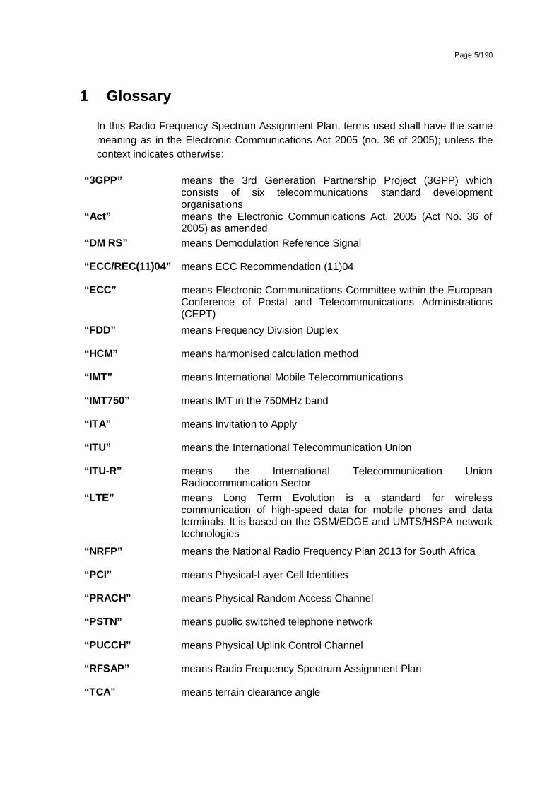
Page 5/190
1 Glossary
In this Radio Frequency Spectrum Assignment Plan, terms used shall have the same meaning as in the Electronic Communications Act 2005 (no. 36 of 2005); unless the context indicates otherwise:
“3GPP” means the 3rd Generation Partnership Project (3GPP) which consists of six telecommunications standard development organisations
“Act” means the Electronic Communications Act, 2005 (Act No. 36 of 2005) as amended
“DM RS” means Demodulation Reference Signal
“ECC/REC(11)04” means ECC Recommendation (11)04
“ECC” means Electronic Communications Committee within the European Conference of Postal and Telecommunications Administrations (CEPT)
“FDD” means Frequency Division Duplex
“HCM” means harmonised calculation method
“IMT” means International Mobile Telecommunications
“IMT750” means IMT in the 750MHz band
“ITA” means Invitation to Apply
“ITU” means the International Telecommunication Union
“ITU-R” means the International Telecommunication Union Radiocommunication Sector
“LTE” means Long Term Evolution is a standard for wireless communication of high-speed data for mobile phones and data terminals. It is based on the GSM/EDGE and UMTS/HSPA network technologies
“NRFP” means the National Radio Frequency Plan 2013 for South Africa
“PCI” means Physical-Layer Cell Identities
“PRACH” means Physical Random Access Channel
“PSTN” means public switched telephone network
“PUCCH” means Physical Uplink Control Channel
“RFSAP” means Radio Frequency Spectrum Assignment Plan
“TCA” means terrain clearance angle

Page 6/190
“TDD” means Time Division Duplex
“WRC-12” means World Radio Conference 2012 held in Geneva
“WRC-15” means the World Radio Conference planned to be held in 2015
2 Purpose 2.1 A Radio Frequency Spectrum Assignment Plan (RFSAP) provides information on
the requirements attached to the use of a frequency band in line with the allocation and other information in the National Radio Frequency Plan (NRFP). This information includes technical characteristics of radio systems, frequency channelling, coordination and details on required migration of existing users of the band and the expected method of assignment.
2.2 This Frequency Assignment Plan states the requirements for the utilization of the frequency band between 733 MHz and 758 MHz for IMT750.
2.3 The ITU states that International Mobile Telecommunications (IMT) systems are mobile systems that provide access to a wide range of telecommunication services including advanced mobile services, supported by mobile and fixed networks, which are increasingly packet-based.
Key features:
a high degree of commonality of functionality worldwide while retaining the flexibility to support a wide range of services and applications in a cost efficient manner
compatibility of services within IMT and with fixed networks
capability of interworking with other radio access systems
high quality mobile services
user equipment suitable for worldwide use
user-friendly applications, services and equipment
worldwide roaming capability
enhanced peak data rates to support advanced services and applications
3 General 3.1 Technical characteristics of equipment used in IMT750 systems shall conform to all
applicable South African standards, international standards, International Telecommunications Union (ITU) and its radio regulations as agreed and adopted by South Africa
3.2 All installations must comply with safety rules as specified in applicable standards.
3.3 The equipment used shall be certified under South African law and regulations.

Page 7/190
3.4 The allocation of this frequency band and the information in this Radio Frequency Spectrum Assignment Plan (RFSAP) are subject to review.
3.5 Frequency bands assigned for IMT750 include bands between 733-758 MHz
3.6 Likely use of this band will be for Mobile voice and data communications.
3.7 The technologies which can provide IMT750 services include, but are not limited to:
LTE,
LTE Advanced,
HSPA+,
WiMAX
3.8 Typical technical and operational characteristics of IMT systems as identified as by the ITU are described in the following documents:
Recommendation ITU-R M.2012-1 (02/2014): Detailed specifications of the terrestrial radio interfaces of International Mobile Telecommunications-Advanced (IMT Advanced).
Report ITU-R2241-0 Compatibility studies in relation to Resolution 224 in the bands 698-806 MHz and 790-862 MHz.
Report ITU-R M.2074: Report on Radio Aspects for the terrestrial component of IMT-2000 and systems beyond IMT-2000.
Recommendation ITU-R M.1645 Framework and overall objectives of the future development of IMT-2000 and systems beyond IMT-2000.
Recommendation ITU-R M.1036-4: Frequency arrangements for implementation of the terrestrial component of International Mobile Telecommunications (IMT) in the bands identified for IMT in the Radio Regulations (RR).
4 Channelling Plan 4.1 The frequency band 733 -788 MHz provides a total bandwidth of:
15MHz TDD for IMT750 and two 5 MHz guard bands
4.2 The channel arrangements for the IMT750 band are according to the Region 1 recommendation by the ITU.

Page 8/190
Figure 5: Channel arrangement for IMT750
5 Requirements for usage of radio frequency spectrum 5.1 This chapter covers the minimum key characteristics considered necessary in order
to make the best use of the available frequencies.
5.2 The use of the band is limited for IMT-services.
5.3 Only systems using digital technologies that promote spectral efficiency will be issued with an assignment. Capacity enhancing digital techniques is being rapidly developed and such techniques that promote efficient use of spectrum, without reducing quality of service are encouraged.
5.4 In some cases, a radio system conforming to the requirements of this RFSAP may require modifications if harmful interference is caused to other radio stations or systems.
5.5 The allocation of spectrum and shared services within these bands are found in the National Radio Frequency Plan (NRFP) and an extract of NRFP is shown in Appendix A.
5.6 Maximum radiated power:
5.6.1 Base Station transmissions should not exceed 61dBm/5MHz EIRP.
5.6.2 Mobile Station transmissions should not exceed 23dBm EIRP.
5.6.3 On a case to case basis, higher EIRP may be permitted if acceptable technical justification is provided.
5.6.4 Where appropriate subscriber terminal station should comply with the technical specification outlined under “3GPP TS 36.521-1”.
5.7 In some cases, a radio system conforming to the requirements of this RFSAP may require modifications if major interference is caused to other radio stations or systems.
5.8 Criteria and guidelines for interference mitigation are described in Appendix D.
733
738
753
758
703
788
LegendIMT700 IMT750 Guardband

Page 9/190
6 Implementation 6.1 This Radio Frequency Assignment Plan comes into effect on the 1st January 2016.
6.2 The process of assignment may commence prior to the date referred to in section 6.1.
6.3 No new assignments for IMT750 in the band 733 - 758MHz shall be approved unless they comply with this RFSAP.
7 Co-ordination Requirements 7.1 Use of these frequency bands shall require coordination with the neighbouring
countries within the coordination zones of 6 kilometres in case of LTE-to-LTE or 9 kilometres in case of LTE-to-other technologies from the neighbouring country. The coordination distance is continuously being reviewed and may be updated from time to time.
7.2 The following field strength thresholds have to be assured based on (ECC/REC(11)04 for 790-862MHz. Operator-to-operator coordination may be necessary to avoid interference
In general stations of FDD systems may be used without coordination with a neighbouring country if the mean field strength produced by the cell (all transmitters within the sector) does not exceed the value of 55dBV/m/5MHz at a height of 3m above ground at the borderline between countries and does not exceed a value of 29dBV/m/5MHz at a height of 3m above ground at a distance of 9 km inside the neighbouring country.
In the case that LTE is deployed both sides of the border the field strength levels can be increased to 59 dBV/m/5MHz and 41 dBV/m/5MHz at 6 km.
If TDD is in operation across both sides of a border and is synchronised across the border then field strength levels as well.
For field strength predictions the calculations should be made according to Appendix B. In cases of other frequency block sizes 10*log (frequency block size/5MHz) should be added to the field strength values e.g.:
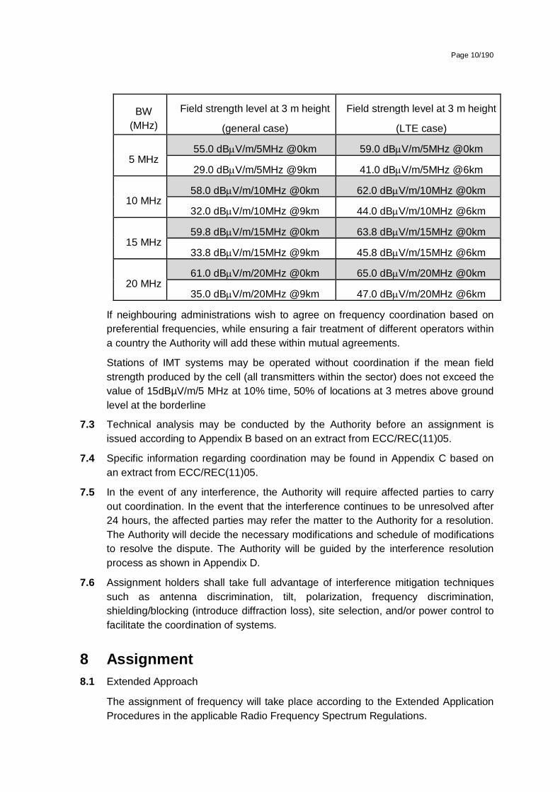
Page 10/190
BW (MHz)
Field strength level at 3 m height
(general case)
Field strength level at 3 m height
(LTE case)
5 MHz 55.0 dBV/m/5MHz @0km 59.0 dBV/m/5MHz @0km
29.0 dBV/m/5MHz @9km 41.0 dBV/m/5MHz @6km
10 MHz 58.0 dBV/m/10MHz @0km 62.0 dBV/m/10MHz @0km
32.0 dBV/m/10MHz @9km 44.0 dBV/m/10MHz @6km
15 MHz 59.8 dBV/m/15MHz @0km 63.8 dBV/m/15MHz @0km
33.8 dBV/m/15MHz @9km 45.8 dBV/m/15MHz @6km
20 MHz 61.0 dBV/m/20MHz @0km 65.0 dBV/m/20MHz @0km
35.0 dBV/m/20MHz @9km 47.0 dBV/m/20MHz @6km
If neighbouring administrations wish to agree on frequency coordination based on preferential frequencies, while ensuring a fair treatment of different operators within a country the Authority will add these within mutual agreements.
Stations of IMT systems may be operated without coordination if the mean field strength produced by the cell (all transmitters within the sector) does not exceed the value of 15dBµV/m/5 MHz at 10% time, 50% of locations at 3 metres above ground level at the borderline
7.3 Technical analysis may be conducted by the Authority before an assignment is issued according to Appendix B based on an extract from ECC/REC(11)05.
7.4 Specific information regarding coordination may be found in Appendix C based on an extract from ECC/REC(11)05.
7.5 In the event of any interference, the Authority will require affected parties to carry out coordination. In the event that the interference continues to be unresolved after 24 hours, the affected parties may refer the matter to the Authority for a resolution. The Authority will decide the necessary modifications and schedule of modifications to resolve the dispute. The Authority will be guided by the interference resolution process as shown in Appendix D.
7.6 Assignment holders shall take full advantage of interference mitigation techniques such as antenna discrimination, tilt, polarization, frequency discrimination, shielding/blocking (introduce diffraction loss), site selection, and/or power control to facilitate the coordination of systems.
8 Assignment 8.1 Extended Approach
The assignment of frequency will take place according to the Extended Application Procedures in the applicable Radio Frequency Spectrum Regulations.

Page 11/190
9 Revocation 9.1 Existing radio frequency spectrum licences for the use of the band are revoked.
10 Radio Frequency Migration 10.1.1 Specific Procedure
WRC 12 resolved to allocate the frequency band 694-790 MHz in Region 1 to the mobile except aeronautical mobile on a co-primary basis and to identify it for IMT and that the allocation is effective immediately after WRC-15.
Any Studio Transmission Links in this band must be migrated out to point to point fixed assignments.
Appropriate destination bands for STL’s are:
The 2025 – 2110 MHz (paired with 2200 – 2285 MHz).
Self Help Stations must be migrated out as per latest version of Terrestrial Broadcasting Frequency Plan.

Page 12/190
Appendix A National Radio Frequency Plan
ITU Region 1 allocations and footnote
South African allocations and footnotes
Typical Applications Comments
470-790MHz(694-790)
BROADCASTING
5.149 5.291A 5.294 5.296 5.300 5.304 5.306 5.311A 5.312 5.312A
470-790 MHz
BROADCASTING
RADIO ASTRONOMY
MOBILE except aeronautical mobile NF9
5.149 5.311A 5.312A
Television Broadcasting (470 – 854 MHz)
Radio Astronomy (606-614 MHz)
IMT700 (694-790 MHz)
Broadcasting Allotments in accordance with GE89 plan in the process of conversion to GE06. Broadcast assignments in accordance with the latest version of the Terrestrial Broadcasting Frequency Plan. The use of ‘White Spaces’ in this band is under consideration (subject to NINP basis to users under a primary allocation.)

Page 13/190
Appendix B Propagation Model
The following methods are proposed for assessment of anticipated interference inside neighboring country based on established trigger values. Due to complexity of radio-wave propagation nature different methods are proposed to be considered by administrations and are included here for guidance purposes only. It should be noted that following methods provide theoretical predictions based on available terrain knowledge. It is practically impossible to recreate these methods with measurement procedures in the field. Therefore only some approximation of measurements could be used to check compliance with those methods based on practical measurement procedures. The details of such approximation are not included in this recommendation and should be negotiated between countries based on their radio monitoring practices.
Path specific model
Where appropriate detailed terrain data is available, the propagation model for interference field strength prediction is the latest version of ITU-R Rec. P.452, For the relevant transmitting terminal, predictions of path loss would be made at x km steps along radials of y km at z degree intervals5. The values for those receiver locations within the neighbouring country would be used to construct a histogram of path loss – and if more than 10% of predicted values exceed the threshold the station should be required to be coordinated.
Site General model
If it is not desirable to utilise detailed terrain height data for the propagation modelling in the border area, the basic model to be used to trigger coordination between administrations and to decide, if co-ordination is necessary, is ITU-R Rec. P.1546, “Method for point to area predictions for terrestrial services in the frequency range 30 to 3000 MHz”. This model is to be employed for 50% locations, 10% time and using a receiver height of 3m. For specific reception areas where terrain roughness adjustments for improved accuracy of field strength prediction are needed, administrations may use correction factors according to terrain irregularity and/or an averaged value of the TCA parameter in order to describe the roughness of the area on and around the coordination line.
Administrations and/or operators concerned may agree to deviate from the aforementioned model by mutual consent.
5 . Values for x, y, z and path specific field strength levels are to be agreed between the administrations concerned

Page 14/190
Area calculations
In the case where greater accuracy is required, administrations and operators may use the area calculation below. For calculations, all the pixels of a given geographical area to be agreed between the Administrations concerned in a neighbouring country are taken into consideration. For the relevant base station, predictions of path loss should be made for all the pixels of a given geographical area from a base station and at a receiver antenna height of 3m above ground.
For evaluation,
• only 10 percent of the number of geographical area between the borderline (including also the borderline) and the 6 km line itself inside the neighbouring country may be interfered by higher field strength than the trigger field strength value given for the borderline in Annex 1 and 2 at a height of 3 m above ground.
• only 10 percent of the number of geographical area between the 6 km (including also 6km line) and 12 km line inside the neighbouring country may be interfered by higher field strength than the trigger field strength value given for the 6 km line in Annex 1 and 2 at a height of 3 m above ground.
It is recommended that during area calculations not only detailed terrain data but also clutter data be taken into account. Use of correction factors for clutter is crucial in particular where the border area is ‘open’ or ‘quasi-open’ from the point of view of clutter or where the interfering base station is just a few kilometres from a borderline.
If the distance between a base station and a terrain point of a borderline is closer than or equal to 1 km, free space propagation model needs to be applied. Furthermore, if there is no terrain obstacle within the 1st Fresnel zone, also the free space propagation model should be applied.
If clutter data is not available, it is proposed to extend the usage of free space propagation model to a few kilometres, depending on the clutter situation in border areas.
For area type interference calculations, propagation models with path specific terrain correction factors are recommended (e.g. Recommendation ITU–R P.1546 with the terrain clearance angle correction factor TCA, HCM method with the terrain clearance angle correction factor or Recommendation ITU–R P.1812).
As to correction factors for clutters ‘open area’ and ‘quasi-open area’, 20 dB and 15 dB should be used respectively. Recommendation ITU–R P.1406 should be used if a finer selection of clutter is required.
It must be noted that terrain irregularity factor Δh is not recommended to be used in area calculations. Administrations and/or operators concerned may agree to deviate from the aforementioned models by mutual consent.

Page 15/190
Appendix C Coordination for IMT-Systems
PREFERENTIAL PHYSICAL-LAYER CELL IDENTITIES (PCI) FOR IMT-2000/LTE6
The following is extracted from ECC/REC(11)05 as an operational example and can be adapted for the SADC-countries
PCI co-ordination is only needed when channel centre frequencies are aligned independent of the channel bandwidth.
3GPP TS 36.211 defines 168 “unique physical-layer cell-identity groups” in §6.11, numbered 0…167, hereafter called “PCI groups”. Within each PCI group there are three separate PCIs giving 504 PCIs in total.
Administrations should agree on a repartition of these 504 PCI on an equitable basis when channel centre frequencies are aligned as shown in the Table below. It has to be noted that dividing the PCI groups or PCI’s is equivalent. Each country can use all PCI groups away from the border areas.
As shown in the table below, the PCI’s should be divided into 6 sub-sets containing each one sixth of the available PCI’s. Each country is allocated three sets (half of the PCI’s) in a bilateral case, and two sets (one third of the PCI’s) in a trilateral case.
Four types of countries are defined in a way such that no country will use the same code set as any one of its neighbours. The following lists describe the distribution of European countries (which needs to be adapted for SADC):
Type country 1: BEL, CVA, CYP, CZE, DNK, E, FIN, GRC, IRL, ISL, LTU, MCO, SMR, SUI, SVN, UKR, AZE, SRB.
Type country 2: AND, BIH, BLR, BUL, D, EST, G, HNG, I, MDA, RUS (Exclave), GEO
Type country 3: ALB, AUT, F, HOL, HRV, POL, POR, ROU, RUS, S, MLT
Type country 4:LIE, LUX, LVA, MKD, MNE, NOR, SVK, TUR.
For each type of country, the following tables and figure describe the sharing of the PCI’s with its neighbouring countries, with the following conventions of writing:
Preferential PCI
non-preferential PCI
6 ECC/REC(11)05

Page 16/190
The 504 physical-layer cell-identities should be divided into the following 6 sub-sets when the carrier frequencies are aligned in border areas:
PCI Set A
Set B Set C Set D Set E Set F PCI
Set A Set B Set C Set D Set E Set F
Country 1 0..83
84..167 168..251 252..335
336..419 420..503 Country 2 0..83
84..16
7 168..25
1 252..335
336..4
19 420..503
Border 1-2 Border 2-1
Zone 1-2-3 Zone 2-3-1
Border 1-3 Border 2-3
Zone 1-2-4 Zone 2-1-4
Border 1-4 Border 2-4
Zone 1-3-4 Zone 2-3-4
PCI Set A Set B Set C Set D Set E Set F PCI
Set A Set B Set C Set D Set E Set F
Country 3 0..83
84..167 168..251 252..335
336..419 420..503 Country 4 0..83
84..16
7 168..25
1 252..335
336..4
19 420..503
Border 3-2 Border 4-1
Zone 3-1-2 Zone 4-1-2
Border 3-1 Border 4-2
Zone 3-1-4 Zone 4-2-3
Border 3-4 Border 4-3
Zone 3-2-4 Zone 4-3-1
Notes 1) All PCI’s are available in areas away from the border. 2) In certain specific cases (e.g. AUT/HRV) where the distance between two countries of the same type number is very small (< few 10s km), it may be necessary to address the situation in bi/multilateral coordination agreements as necessary, and may include further subdivision of the allocated codes in certain areas.

Page 17/190
GUIDANCE ON THE CONSIDERATION OF LTE RADIO PARAMETERS FOR USE IN BILATERAL AND MULTI LATERAL AGREEMENTS
This Annex is provided for guidance purposes for use in bi-lateral and multilateral discussions. For LTE, it may be beneficial to coordinate other radio parameters besides PCI in order to minimise deteriorating effects of uplink interference.
The parameters described in this Annex are usually optimised during LTE radio network planning of an operator’s network. The idea of optimisation is to plan the parameters taking into account specific correlation properties of the uplink control signals which enable more stable and predictable operation of the network. In the cross-border scenario the optimisation of parameters among neighbouring operators could provide better control of uplink interference. However because of the difference between intra-network and inter-network interference and due to limited experience in the LTE cross-border deployment it is difficult to assess the benefits of such optimisation. The following guidance provides the basis for operators to consider in border areas in case of high levels of uplink interference.
1. Demodulation Reference Signal (DM RS) coordination
Demodulation reference signals (DM RS) are transmitted in the uplink and used for channel estimation. There is a risk of intercell interference between neighbouring cells even in case of no frame synchronisation. That is why special measures for DM RS allocation between networks in neighbouring countries occupying the same channel may need to be applied. The case of partial channel overlap has not been studied but due to DM RS occupying resource blocks of separate users there is a risk of DM RS collisions between neighbouring networks when the subcarriers positions coincide (the frequency offset between central carriers of neighbouring networks is multiple of 300 kHz). Some minor benefits from DM RS coordination in these particular cases could be expected.
There are a number of possible approaches to the coordination of DM RS:
In basic planning procedure only 30 DM RS sequence groups with favourable correlation characteristics are available: {0…29}. In this case each cell could be assigned one of the 30 DM RS sequence groups providing cluster size of 30.
It is possible to extend each DM RS sequence group to generate up to 12 time shifted sequence groups by applying the cyclic shift parameter stated in 3GPP TS 36.211. For example each tri-sector site could be assigned one DM RS sequence group with each co-sited cell having its own cyclic shift of 2π/3 which provides cluster size 30 only with 10 DM RS sequence groups. The latter case corresponds well to the case of DM RS sequence groups repartition between neighbouring countries when only limited number of groups is available for network planning. The drawback of DM RS sequence group cyclic shift is a loss of orthogonally of DM RS due to fading channels which has been found only recently during first trials of LTE and caused throughput loss as well as time alignment problems.
Another approach for DM RS coordination is to implement dynamic DM RS sequence group allocation also called pseudo-random group hopping. In this method nearby

Page 18/190
cells are grouped into clusters up to 30 cells and within each cell cluster the same hopping-pattern is used. At the border of two clusters inter-cell interference is averaged since two different hopping patterns are utilised. There are 17 defined hopping patterns, numbered {0…16}, which leads to some minor unfairness in case of apportioning these patterns between neighbouring countries. Even in a trilateral case each operator will have at least 5 hopping patterns available near the border which should be enough for planning purposes. It should be noted the pseudo-random group hopping option could be absent in the first generations of LTE equipment.
The decision of which of these methods to use in cross-border coordination should be agreed upon by the interested parties. Specific DM RS sequence groups or hopping patterns repartition is not provided in the text of this Recommendation but could be deduced in a similar manner to the PCI repartition.
2. Physical Random Access Channel (PRACH) coordination
Another radio network parameter which is considered during radio network planning is PRACH configuration which is needed to distinguish random access requests addressed to different cells. PRACH resources are allocated by specifying the PRACH Resource Blocks time positions within the uplink frame, their frequency position within the LTE channel bandwidth and by apportioning cell-specific root sequences. During radio network planning these parameters are usually used in the following way:
time positions for PRACH resource allocations are usually used to create time collision of PRACH resources of co-sited/frame synchronised cells because PRACH-to-PRACH interference is usually less severe than PUSCH-to-PRACH interference;
frequency positions within the LTE channel bandwidth is usually the same for all cells, again because PRACH-to-PRACH interference case is more favourable one.
cell-specific root sequences are used to distinguish between PRACH requests addressed to different cells.
For cross-border coordination it is proposed to use frequency position offsets to exclude the possibility of so-called “ghost” PRACH requests caused by neighbouring networks. The PRACH is configured in LTE to use only 6 Resource Blocks or 1.08 MHz of the LTE channel bandwidth except in regions used by PUCCH. In case of overlapping or partially overlapping channel bandwidths of neighbouring networks it is enough to establish non-overlapping PRACH frequency blocks to perform coordination. Because it is difficult to establish an implementation dependent procedure for such allocation it will be the responsibility of operators to manage such frequency separation during coordination discussions.
In early implementation it is possible that very limited number of frequency positions will be supported by LTE equipment which will not be enough to coordinate in the trilateral case. In such cases root-sequence repartition could be used. There are 838 root sequences in total to be distributed between cells, numbered {0..837}. There are two numbering schemes for PRACH root sequences (physical and logical) and that only logical root sequences numbering needs be used for coordination. Unfortunately the

Page 19/190
process of root sequences planning doesn’t involve direct mapping of root sequences between cells because the number of root sequences needed for one cell is dependent on the cell range. The table showing such interdependency is presented below:
PRACH Configuration Number of root seq. per cell Cell Range (km)
1 1 0.7
2 2 1
3 2 1.4
4 2 2
5 2 2.5
6 3 3.4
7 3 4.3
8 4 5.4
9 5 7.3
10 6 9.7
11 8 12.1
12 10 15.8
13 13 22.7
14 22 38.7
15 32 58.7
0 64 118.8
Thus in the case of root sequence reparation it will be the responsibility of radio network planners to assign the correct number of root sequences in order to not to overlap with the root sequence ranges of other operators. It also should be noted that different root sequences have different cubic metrics and correlation properties which affect PRACH coverage performance and planning of so-called high-speed cells. For simplicity of cross-border coordination it is proposed to ignore these properties.
In summary it should be stipulated that frequency separation of PRACH resources should be used as the main coordination method. PRACH root sequences repartition should be avoided and used only in exceptional cases. Specific PRACH root sequences repartition is not provided in the text of this Recommendation but could be deduced in a similar manner to the PCI repartition.

Page 20/190
Appendix D Interference Resolution Process
When requesting coordination the relevant characteristics of the base station and the code or PCI group number should be forwarded to the Administration affected. All of the following characteristics should be Included:
a) carrier frequency [MHz]
b) name of transmitter station
c) country of location of transmitter station
d) geographical coordinates [latitude, longitude]
e) effective antenna height [m]
f) antenna polarisation
g) antenna azimuth [deg]
h) antenna gain [dBi]
i) effective radiated power [dBW]
j) expected coverage zone or radius [km]
k) date of entry into service [month, year].
l) code group number used
m) antenna tilt [deg]
The Administration affected shall evaluate the request for coordination and shall within 30 days notify the result of the evaluation to the Administration requesting coordination. If in the course of the coordination procedure the Administration affected requires additional information, it may request such information.
If in the course of the coordination procedure an Administration may request additional information.
If no reply is received by the Administration requesting coordination within 30 days it may send a reminder to the Administration affected. An Administration not having responded within 30 days following communication of the reminder shall be deemed to have given its consent and the code co-ordination may be put into use with the characteristics given in the request for coordination.
The periods mentioned above may be extended by common consent.

Page 1/190
Government Gazette
GENERAL NOTICE
NOTICE 1013 OF 2014
INDEPENDENT COMMUNICATIONS AUTHORITY OF SOUTH AFRICA
PURSUANT TO SECTION 4 (1) OF THE ELECTRONIC COMMUNICATIONS ACT 2005, (ACT NO. 36 OF 2005)
HEREBY ISSUES A NOTICE REGARDING THE DRAFT RADIO FREQUENCY SPECTRUM ASSIGNMENT PLAN FOR THE FREQUENCY BAND 791 TO 821 MHz AND 832 TO 862 MHz FOR CONSULTATION.
1. The Independent Communications Authority of South Africa ("the Authority"), hereby publishes Draft Radio Frequency Spectrum Assignment Plan for the frequency band 791 to 821 MHz and 832 to 862 MHz for consultation in terms of sections 2 (d), (e) and 4, read with sections 30, 31(4), and 33 of the Electronic Communications Act (Act No. 36 of 2005) and read with Regulation 3 of the Radio Frequency Spectrum Regulations 2011 and read with the IMT Roadmap 2014.
2. This Radio Frequency Spectrum Assignment Plan supersedes any previous spectrum assignment arrangements for the same spectrum location.
3. Interested persons are hereby invited to submit written representations, including an electronic version of the representation in Microsoft Word, of their views on the Draft Radio Frequency Spectrum Assignment Plan for the frequency band 791 to

Page 2/190
821 MHz and 832 to 862 MHz by no later than 16h00 on Friday 28th November 2014.
4. Written representations or enquiries may be directed to:
The Independent Communications Authority of South Africa (ICASA)
Pinmill Farm Block A
164 Katherine Street
South Africa
or
Private Bag XI0002
Sandton
2146
Attention:
Mr Manyaapelo Richard Makgotlho
e-mail: [email protected]
5. All written representations submitted to the Authority pursuant to this notice shall be made available for inspection by interested persons from 2nd November 2014 at the ICASA Library or website and copies of such representations and documents will be obtainable on payment of a fee.
Where persons making representations require that their representation, or part thereof, be treated confidentially, then an applications in terms of section 4D of the ICASA Act, 2000 (Act No. 13 of 2000) must be lodged with the Authority. Such an application must be submitted simultaneously with the representation on the draft regulations and plan. Respondents are requested to separate any confidential material into a clearly marked confidential annexure. If, however, the request for confidentiality is refused, the person making the request will be allowed to withdraw the representation or document in question.
_______________ Dr SS MNCUBE CHAIRPERSON
Page 3/190
Radio Frequency Spectrum Assignment Plan
Rules for Services operating in the Frequency Band
from 791 to 821MHz and 832 to 862MHz
(IMT800)

Page 4/190
Table of Contents
1 Glossary ............................................................................................. 5
2 Purpose .............................................................................................. 6
3 General ............................................................................................... 6
4 Channelling Plan ................................................................................ 8
5 Requirements for usage of radio frequency spectrum ................... 8
6 Implementation .................................................................................. 9
7 Co-ordination Requirements ............................................................. 9
8 Assignment ...................................................................................... 11
9 Revocation ....................................................................................... 11
10 Radio Frequency Migration ............................................................. 11
Appendix A National Radio Frequency Plan ............................................... 12
Appendix B Propagation Model.................................................................... 13
Appendix C Coordination for IMT-Systems ................................................. 15
Appendix D Interference Resolution Process ............................................. 20

Page 5/190
1 Glossary
In this Radio Frequency Spectrum Assignment Plan, terms used shall have the same meaning as in the Electronic Communications Act 2005 (no. 36 of 2005); unless the context indicates otherwise:
“3GPP” means the 3rd Generation Partnership Project (3GPP) which consists of six telecommunications standard development organisations
“Act” means the Electronic Communications Act, 2005 (Act No. 36 of 2005) as amended
“DM RS” means Demodulation Reference Signal
“ECC/REC(11)04” means ECC Recommendation (11)04
“ECC” means Electronic Communications Committee within the European Conference of Postal and Telecommunications Administrations (CEPT)
“FDD” means Frequency Division Duplex
“HCM” means harmonised calculation method
“IMT” means International Mobile Telecommunications
“IMT800” means IMT in the 800MHz band
“ITA” means Invitation to Apply
“ITU” means the International Telecommunication Union
“ITU-R” means the International Telecommunication Union Radiocommunication Sector
“LTE” means Long Term Evolution is a standard for wireless communication of high-speed data for mobile phones and data terminals. It is based on the GSM/EDGE and UMTS/HSPA network technologies
“NRFP” means the National Radio Frequency Plan 2013 for South Africa
“PCI” means Physical-Layer Cell Identities
“PPDR” means Public Protection and Disaster Relief as defined in ITU-R Report M.2033.
“PRACH” means Physical Random Access Channel
“PSTN” means public switched telephone network
“PUCCH” means Physical Uplink Control Channel
“RFSAP” means Radio Frequency Spectrum Assignment Plan

Page 6/190
“TCA” means terrain clearance angle
“TDD” means Time Division Duplex
“WRC-12” means World Radio Conference 2012 held in Geneva
“WRC-15” means the World Radio Conference planned to be held in 2015
2 Purpose 2.1 A Radio Frequency Spectrum Assignment Plan (RFSAP) provides information on
the requirements attached to the use of a frequency band in line with the allocation and other information in the National Radio Frequency Plan (NRFP). This information includes technical characteristics of radio systems, frequency channelling, coordination and details on required migration of existing users of the band and the expected method of assignment.
2.2 This Radio Frequency Spectrum Assignment Plan states the requirements for the utilization of the frequency band between 791-821 MHz paired with 832-862 MHz for IMT800.
2.3 The ITU states that International Mobile Telecommunications (IMT) systems are mobile systems that provide access to a wide range of telecommunication services including advanced mobile services, supported by mobile and fixed networks, which are increasingly packet-based.
Key features:
a high degree of commonality of functionality worldwide while retaining the flexibility to support a wide range of services and applications in a cost efficient manner
compatibility of services within IMT and with fixed networks
capability of interworking with other radio access systems
high quality mobile services
user equipment suitable for worldwide use
user-friendly applications, services and equipment
worldwide roaming capability
enhanced peak data rates to support advanced services and applications
3 General 3.1 Technical characteristics of equipment used in IMT800 systems shall conform to all
applicable South African standards, international standards, International Telecommunications Union (ITU) and its radio regulations as agreed and adopted by South Africa

Page 7/190
3.2 All installations must comply with safety rules as specified in applicable standards.
3.3 The equipment used shall be certified under South African law and regulations.
3.4 The allocation of this frequency band and the information in this Radio Frequency Spectrum Assignment Plan (RFSAP) are subject to review.
3.5 Frequency bands assigned for IMT800 include bands 791-821MHz paired with 832-862MHz.
3.6 Likely use of this band will be for Mobile voice and data communications.
3.7 The technologies which can provide IMT800 services include, but are not limited to:
LTE,
LTE Advanced,
HSPA+,
WiMAX
3.8 Typical technical and operational characteristics of IMT systems as identified as by the ITU are described in the following documents:
Recommendation ITU-R M.2012-1 (02/2014): Detailed specifications of the terrestrial radio interfaces of International Mobile Telecommunications-Advanced (IMT Advanced).
Report ITU-R2241-0 Compatibility studies in relation to Resolution 224 in the bands 698-806 MHz and 790-862 MHz.
Report ITU-R M.2074: Report on Radio Aspects for the terrestrial component of IMT-2000 and systems beyond IMT-2000.
Recommendation ITU-R M.1645 Framework and overall objectives of the future development of IMT-2000 and systems beyond IMT-2000.
Recommendation ITU-R M.1036-4: Frequency arrangements for implementation of the terrestrial component of International Mobile Telecommunications (IMT) in the bands identified for IMT in the Radio Regulations (RR).

Page 8/190
4 Channelling Plan 4.1 The frequency band 791-821MHz paired with 832-862MHz provides a total
bandwidth of
2×30MHz FDD for IMT800
4.2 Channel arrangements
4.3 The channel arrangements for the IMT800 band are based on the Region 1 recommendation by the ITU. Adjacent assignments are also shown in the channelling plan.
Figure 6: Channel arrangements for IMT800
5 Requirements for usage of radio frequency spectrum 5.1 This chapter covers the minimum key characteristics considered necessary in order
to make the best use of the available frequencies.
5.2 The use of the band is limited for IMT-services.
5.3 Only systems using digital technologies that promote spectral efficiency will be issued with an assignment. Capacity enhancing digital techniques is being rapidly developed and such techniques that promote efficient use of spectrum, without reducing quality of service are encouraged.
5.4 In some cases, a radio system conforming to the requirements of this RFSAP may require modifications if harmful interference is caused to other radio stations or systems.
5.5 The allocation of spectrum and shared services within these bands are found in the National Radio Frequency Plan (NRFP) and an extract of NRFP is shown in 10.3Appendix A.
5.6 Maximum radiated power
Legend
791
821
832
862
IMT800 Uplink IMT800 Downlink
Centre Gap (Potential
IMT850

Page 9/190
5.6.1 Base Station transmissions should not exceed 61dBm/5MHz EIRP.
5.6.2 Mobile Station transmissions should not exceed 23dBm EIRP.
5.6.3 On a case to case basis, higher EIRP may be permitted if acceptable technical justification is provided.
5.6.4 Where appropriate subscriber terminal station should comply with the technical specification outlined under “3GPP TS 36.521-1”.
5.7 In some cases, a radio system conforming to the requirements of this RFSAP may require modifications if major interference is caused to other radio stations or systems.
5.8 Criteria and guidelines for interference mitigation are described in 0.
6 Implementation 6.1 This Radio Frequency Assignment Plan comes into effect on the 1st July 2015.
6.2 The process of assignment may commence prior to the date referred to in section 6.1.
6.3 No new assignment for IMT800 in the band 791-821MHz paired with 832-862MHz shall be approved unless they comply with this RFSAP.
7 Co-ordination Requirements 7.1 Use of these frequency bands shall require coordination with the neighbouring
countries within the coordination zones of 6 kilometres in case of LTE-to-LTE or 9 kilometres in case of LTE-to-other technologies from the neighbouring country. The coordination distance is continuously being reviewed and may be updated from time to time.
7.2 The following field strength thresholds have to be assured based on (ECC/REC(11)04 for 790-862MHz. Operator-to-operator coordination may be necessary to avoid interference
In general stations of FDD systems may be used without coordination with a neighbouring country if the mean field strength produced by the cell (all transmitters within the sector) does not exceed the value of 55dBV/m/5MHz at a height of 3m above ground at the borderline between countries and does not exceed a value of 29dBV/m/5MHz at a height of 3m above ground at a distance of 9 km inside the neighbouring country.
In the case that LTE is deployed both sides of the border the field strength levels can be increased to 59 dBV/m/5MHz and 41 dBV/m/5MHz at 6 km.
If TDD is in operation across both sides of a border and is synchronised across the border then field strength levels as well.

Page 10/190
For field strength predictions the calculations should be made according to Appendix B. In cases of other frequency block sizes 10*log (frequency block size/5MHz) should be added to the field strength values e.g.:
BW (MHz)
Field strength level at 3 m height
(general case)
Field strength level at 3 m height
(LTE case)
5 MHz 55.0 dBV/m/5MHz @0km 59.0 dBV/m/5MHz @0km
29.0 dBV/m/5MHz @9km 41.0 dBV/m/5MHz @6km
10 MHz 58.0 dBV/m/10MHz @0km 62.0 dBV/m/10MHz @0km
32.0 dBV/m/10MHz @9km 44.0 dBV/m/10MHz @6km
15 MHz 59.8 dBV/m/15MHz @0km 63.8 dBV/m/15MHz @0km
33.8 dBV/m/15MHz @9km 45.8 dBV/m/15MHz @6km
20 MHz 61.0 dBV/m/20MHz @0km 65.0 dBV/m/20MHz @0km
35.0 dBV/m/20MHz @9km 47.0 dBV/m/20MHz @6km
If neighbouring administrations wish to agree on frequency coordination based on preferential frequencies, while ensuring a fair treatment of different operators within a country the Authority will add these within mutual agreements.
Stations of IMT systems may be operated without coordination if the mean field strength produced by the cell (all transmitters within the sector) does not exceed the value of 15dBµV/m/5 MHz at 10% time, 50% of locations at 3 metres above ground level at the borderline
7.3 Technical analysis may be conducted by the Authority before an assignment is issued according to Appendix B based on an extract from ECC/REC(11)05.
7.4 Specific information regarding coordination may be found in Appendix C based on an extract from ECC/REC(11)05.
7.5 In the event of any interference, the Authority will require affected parties to carry out coordination. In the event that the interference continues to be unresolved after 24 hours, the affected parties may refer the matter to the Authority for a resolution. The Authority will decide the necessary modifications and schedule of modifications to resolve the dispute. The Authority will be guided by the interference resolution process as shown in 0.
7.6 Assignment holders shall take full advantage of interference mitigation techniques such as antenna discrimination, tilt, polarization, frequency discrimination, shielding/blocking (introduce diffraction loss), site selection, and/or power control to facilitate the coordination of systems.

Page 11/190
8 Assignment 8.1 Extended Approach
The assignment of frequency will take place according to the Extended Application Procedures in the applicable Radio Frequency Spectrum Regulations.
9 Revocation 9.1 Existing radio frequency spectrum licences for the use of the band are revoked.
10 Radio Frequency Migration 10.1.1 Specific Procedure
This band has been allocated to IMT (Terrestrial) for Region 1 countries at WRC-07 and is often termed Digital Dividend 1. Currently this band is occupied by UHF TV.
It is intended as per latest version of Terrestrial Broadcasting Frequency Plan that:
TV will migrate out of this band as per the Terrestrial Broadcasting Frequency Plan in line with the specified Analogue switch off date.
The small number of Studio Transmitter Links in this band must be migrated out and given point to point fixed assignments.
Appropriate destination bands for STL’s are:
The 2025 – 2110 MHz (paired with 2200 – 2285 MHz).
Self Help Stations must be migrated out as per latest version of Terrestrial Broadcasting Frequency Plan.

Page 12/190
Appendix A National Radio Frequency Plan
ITU Region 1 allocations and footnote
South African allocations and footnotes
Typical Applications Comments
790-862 MHz
FIXED
MOBILE except aeronautical mobile 5.317A
BROADCASTING
5.312 5.314 5.315 5.316 5.316A 5.319
790-862 MHz
FIXED
MOBILE except aeronautical mobile 5.316B 5.317A NF9
BROADCASTING
5.316A
Fixed Links (856 – 864.1 MHz)
IMT800 BTX (791 – 821 MHz)
Mobile Wireless Access (827.775 – 832.695 MHz)
IMT800 MTX (832. 695 – 862 MHz)
Television Broadcasting (470 – 854 MHz)
The fixed links will be migrated along with the broadcasting service in line with Radio Frequency Migration Plan.
Paired with 832 – 862 MHz
Paired with Access (872.775 – 877.695 MHz)
Paired with 791 – 821 MHz
Broadcasting Allotments in accordance with GE89 plan in the process of conversion to GE06. Broadcast assignments in accordance with the latest version of the Terrestrial Broadcasting Frequency Plan.

Page 13/190
Appendix B Propagation Model
The following methods are proposed for assessment of anticipated interference inside neighboring country based on established trigger values. Due to complexity of radio-wave propagation nature different methods are proposed to be considered by administrations and are included here for guidance purposes only. It should be noted that following methods provide theoretical predictions based on available terrain knowledge. It is practically impossible to recreate these methods with measurement procedures in the field. Therefore only some approximation of measurements could be used to check compliance with those methods based on practical measurement procedures. The details of such approximation are not included in this recommendation and should be negotiated between countries based on their radio monitoring practices.
Path specific model
Where appropriate detailed terrain data is available, the propagation model for interference field strength prediction is the latest version of ITU-R Rec. P.452, For the relevant transmitting terminal, predictions of path loss would be made at x km steps along radials of y km at z degree intervals7. The values for those receiver locations within the neighbouring country would be used to construct a histogram of path loss – and if more than 10% of predicted values exceed the threshold the station should be required to be coordinated.
Site General model
If it is not desirable to utilise detailed terrain height data for the propagation modelling in the border area, the basic model to be used to trigger coordination between administrations and to decide, if co-ordination is necessary, is ITU-R Rec. P.1546, “Method for point to area predictions for terrestrial services in the frequency range 30 to 3000 MHz”. This model is to be employed for 50% locations, 10% time and using a receiver height of 3m. For specific reception areas where terrain roughness adjustments for improved accuracy of field strength prediction are needed, administrations may use correction factors according to terrain irregularity and/or an averaged value of the TCA parameter in order to describe the roughness of the area on and around the coordination line.
Administrations and/or operators concerned may agree to deviate from the aforementioned model by mutual consent.
7 . Values for x, y, z and path specific field strength levels are to be agreed between the administrations concerned

Page 14/190
Area calculations
In the case where greater accuracy is required, administrations and operators may use the area calculation below. For calculations, all the pixels of a given geographical area to be agreed between the Administrations concerned in a neighbouring country are taken into consideration. For the relevant base station, predictions of path loss should be made for all the pixels of a given geographical area from a base station and at a receiver antenna height of 3m above ground.
For evaluation,
• only 10 percent of the number of geographical area between the borderline (including also the borderline) and the 6 km line itself inside the neighbouring country may be interfered by higher field strength than the trigger field strength value given for the borderline in Annex 1 and 2 at a height of 3 m above ground.
• only 10 percent of the number of geographical area between the 6 km (including also 6km line) and 12 km line inside the neighbouring country may be interfered by higher field strength than the trigger field strength value given for the 6 km line in Annex 1 and 2 at a height of 3 m above ground.
It is recommended that during area calculations not only detailed terrain data but also clutter data be taken into account. Use of correction factors for clutter is crucial in particular where the border area is ‘open’ or ‘quasi-open’ from the point of view of clutter or where the interfering base station is just a few kilometres from a borderline.
If the distance between a base station and a terrain point of a borderline is closer than or equal to 1 km, free space propagation model needs to be applied. Furthermore, if there is no terrain obstacle within the 1st Fresnel zone, also the free space propagation model should be applied.
If clutter data is not available, it is proposed to extend the usage of free space propagation model to a few kilometres, depending on the clutter situation in border areas.
For area type interference calculations, propagation models with path specific terrain correction factors are recommended (e.g. Recommendation ITU–R P.1546 with the terrain clearance angle correction factor TCA, HCM method with the terrain clearance angle correction factor or Recommendation ITU–R P.1812).
As to correction factors for clutters ‘open area’ and ‘quasi-open area’, 20 dB and 15 dB should be used respectively. Recommendation ITU–R P.1406 should be used if a finer selection of clutter is required.
It must be noted that terrain irregularity factor Δh is not recommended to be used in area calculations. Administrations and/or operators concerned may agree to deviate from the aforementioned models by mutual consent.

Page 15/190
Appendix C Coordination for IMT-Systems
PREFERENTIAL PHYSICAL-LAYER CELL IDENTITIES (PCI) FOR IMT-2000/LTE8
The following is extracted from ECC/REC(11)05 as an operational example and can be adapted for the SADC-countries
PCI co-ordination is only needed when channel centre frequencies are aligned independent of the channel bandwidth.
3GPP TS 36.211 defines 168 “unique physical-layer cell-identity groups” in §6.11, numbered 0…167, hereafter called “PCI groups”. Within each PCI group there are three separate PCIs giving 504 PCIs in total.
Administrations should agree on a repartition of these 504 PCI on an equitable basis when channel centre frequencies are aligned as shown in the Table below. It has to be noted that dividing the PCI groups or PCI’s is equivalent. Each country can use all PCI groups away from the border areas.
As shown in the table below, the PCI’s should be divided into 6 sub-sets containing each one sixth of the available PCI’s. Each country is allocated three sets (half of the PCI’s) in a bilateral case, and two sets (one third of the PCI’s) in a trilateral case.
Four types of countries are defined in a way such that no country will use the same code set as any one of its neighbours. The following lists describe the distribution of European countries (which needs to be adapted for SADC):
Type country 1: BEL, CVA, CYP, CZE, DNK, E, FIN, GRC, IRL, ISL, LTU, MCO, SMR, SUI, SVN, UKR, AZE, SRB.
Type country 2: AND, BIH, BLR, BUL, D, EST, G, HNG, I, MDA, RUS (Exclave), GEO
Type country 3: ALB, AUT, F, HOL, HRV, POL, POR, ROU, RUS, S, MLT
Type country 4:LIE, LUX, LVA, MKD, MNE, NOR, SVK, TUR.
For each type of country, the following tables and figure describe the sharing of the PCI’s with its neighbouring countries, with the following conventions of writing:
Preferential PCI
non-preferential PCI
8 ECC/REC(11)05

Page 16/190
The 504 physical-layer cell-identities should be divided into the following 6 sub-sets when the carrier frequencies are aligned in border areas:
PCI Set A
Set B Set C Set D Set E Set F PCI
Set A Set B Set C Set D Set E Set F
Country 1 0..83
84..167 168..251 252..335
336..419 420..503 Country 2 0..83
84..16
7 168..25
1 252..335
336..4
19 420..503
Border 1-2 Border 2-1
Zone 1-2-3 Zone 2-3-1
Border 1-3 Border 2-3
Zone 1-2-4 Zone 2-1-4
Border 1-4 Border 2-4
Zone 1-3-4 Zone 2-3-4
PCI Set A Set B Set C Set D Set E Set F PCI
Set A Set B Set C Set D Set E Set F
Country 3 0..83
84..167 168..251 252..335
336..419 420..503 Country 4 0..83
84..16
7 168..25
1 252..335
336..4
19 420..503
Border 3-2 Border 4-1
Zone 3-1-2 Zone 4-1-2
Border 3-1 Border 4-2
Zone 3-1-4 Zone 4-2-3
Border 3-4 Border 4-3
Zone 3-2-4 Zone 4-3-1
Notes 1) All PCI’s are available in areas away from the border. 2) In certain specific cases (e.g. AUT/HRV) where the distance between two countries of the same type number is very small (< few 10s km), it may be necessary to address the situation in bi/multilateral coordination agreements as necessary, and may include further subdivision of the allocated codes in certain areas.

Page 17/190
GUIDANCE ON THE CONSIDERATION OF LTE RADIO PARAMETERS FOR USE IN BILATERAL AND MULTI LATERAL AGREEMENTS
This Annex is provided for guidance purposes for use in bi-lateral and multilateral discussions. For LTE, it may be beneficial to coordinate other radio parameters besides PCI in order to minimise deteriorating effects of uplink interference.
The parameters described in this Annex are usually optimised during LTE radio network planning of an operator’s network. The idea of optimisation is to plan the parameters taking into account specific correlation properties of the uplink control signals which enable more stable and predictable operation of the network. In the cross-border scenario the optimisation of parameters among neighbouring operators could provide better control of uplink interference. However because of the difference between intra-network and inter-network interference and due to limited experience in the LTE cross-border deployment it is difficult to assess the benefits of such optimisation. The following guidance provides the basis for operators to consider in border areas in case of high levels of uplink interference.
1. Demodulation Reference Signal (DM RS) coordination
Demodulation reference signals (DM RS) are transmitted in the uplink and used for channel estimation. There is a risk of intercell interference between neighbouring cells even in case of no frame synchronisation. That is why special measures for DM RS allocation between networks in neighbouring countries occupying the same channel may need to be applied. The case of partial channel overlap has not been studied but due to DM RS occupying resource blocks of separate users there is a risk of DM RS collisions between neighbouring networks when the subcarriers positions coincide (the frequency offset between central carriers of neighbouring networks is multiple of 300 kHz). Some minor benefits from DM RS coordination in these particular cases could be expected.
There are a number of possible approaches to the coordination of DM RS:
In basic planning procedure only 30 DM RS sequence groups with favourable correlation characteristics are available: {0…29}. In this case each cell could be assigned one of the 30 DM RS sequence groups providing cluster size of 30.
It is possible to extend each DM RS sequence group to generate up to 12 time shifted sequence groups by applying the cyclic shift parameter stated in 3GPP TS 36.211. For example each tri-sector site could be assigned one DM RS sequence group with each co-sited cell having its own cyclic shift of 2π/3 which provides cluster size 30 only with 10 DM RS sequence groups. The latter case corresponds well to the case of DM RS sequence groups repartition between neighbouring countries when only limited number of groups is available for network planning. The drawback of DM RS sequence group cyclic shift is a loss of orthogonally of DM RS due to fading channels which has been found only recently during first trials of LTE and caused throughput loss as well as time alignment problems.
Another approach for DM RS coordination is to implement dynamic DM RS sequence group allocation also called pseudo-random group hopping. In this method nearby

Page 18/190
cells are grouped into clusters up to 30 cells and within each cell cluster the same hopping-pattern is used. At the border of two clusters inter-cell interference is averaged since two different hopping patterns are utilised. There are 17 defined hopping patterns, numbered {0…16}, which leads to some minor unfairness in case of apportioning these patterns between neighbouring countries. Even in a trilateral case each operator will have at least 5 hopping patterns available near the border which should be enough for planning purposes. It should be noted the pseudo-random group hopping option could be absent in the first generations of LTE equipment.
The decision of which of these methods to use in cross-border coordination should be agreed upon by the interested parties. Specific DM RS sequence groups or hopping patterns repartition is not provided in the text of this Recommendation but could be deduced in a similar manner to the PCI repartition.
2. Physical Random Access Channel (PRACH) coordination
Another radio network parameter which is considered during radio network planning is PRACH configuration which is needed to distinguish random access requests addressed to different cells. PRACH resources are allocated by specifying the PRACH Resource Blocks time positions within the uplink frame, their frequency position within the LTE channel bandwidth and by apportioning cell-specific root sequences. During radio network planning these parameters are usually used in the following way:
time positions for PRACH resource allocations are usually used to create time collision of PRACH resources of co-sited/frame synchronised cells because PRACH-to-PRACH interference is usually less severe than PUSCH-to-PRACH interference;
frequency positions within the LTE channel bandwidth is usually the same for all cells, again because PRACH-to-PRACH interference case is more favourable one.
cell-specific root sequences are used to distinguish between PRACH requests addressed to different cells.
For cross-border coordination it is proposed to use frequency position offsets to exclude the possibility of so-called “ghost” PRACH requests caused by neighbouring networks. The PRACH is configured in LTE to use only 6 Resource Blocks or 1.08 MHz of the LTE channel bandwidth except in regions used by PUCCH. In case of overlapping or partially overlapping channel bandwidths of neighbouring networks it is enough to establish non-overlapping PRACH frequency blocks to perform coordination. Because it is difficult to establish an implementation dependent procedure for such allocation it will be the responsibility of operators to manage such frequency separation during coordination discussions.
In early implementation it is possible that very limited number of frequency positions will be supported by LTE equipment which will not be enough to coordinate in the trilateral case. In such cases root-sequence repartition could be used. There are 838 root sequences in total to be distributed between cells, numbered {0..837}. There are two numbering schemes for PRACH root sequences (physical and logical) and that only logical root sequences numbering needs be used for coordination. Unfortunately the

Page 19/190
process of root sequences planning doesn’t involve direct mapping of root sequences between cells because the number of root sequences needed for one cell is dependent on the cell range. The table showing such interdependency is presented below:
PRACH Configuration Number of root seq. per cell Cell Range (km)
1 1 0.7
2 2 1
3 2 1.4
4 2 2
5 2 2.5
6 3 3.4
7 3 4.3
8 4 5.4
9 5 7.3
10 6 9.7
11 8 12.1
12 10 15.8
13 13 22.7
14 22 38.7
15 32 58.7
0 64 118.8
Thus in the case of root sequence reparation it will be the responsibility of radio network planners to assign the correct number of root sequences in order to not to overlap with the root sequence ranges of other operators. It also should be noted that different root sequences have different cubic metrics and correlation properties which affect PRACH coverage performance and planning of so-called high-speed cells. For simplicity of cross-border coordination it is proposed to ignore these properties.
In summary it should be stipulated that frequency separation of PRACH resources should be used as the main coordination method. PRACH root sequences repartition should be avoided and used only in exceptional cases. Specific PRACH root sequences repartition is not provided in the text of this Recommendation but could be deduced in a similar manner to the PCI repartition.

Page 20/190
Appendix D Interference Resolution Process
When requesting coordination the relevant characteristics of the base station and the code or PCI group number should be forwarded to the Administration affected. All of the following characteristics should be Included:
a) carrier frequency [MHz]
b) name of transmitter station
c) country of location of transmitter station
d) geographical coordinates [latitude, longitude]
e) effective antenna height [m]
f) antenna polarisation
g) antenna azimuth [deg]
h) antenna gain [dBi]
i) effective radiated power [dBW]
j) expected coverage zone or radius [km]
k) date of entry into service [month, year].
l) code group number used
m) antenna tilt [deg]
The Administration affected shall evaluate the request for coordination and shall within 30 days notify the result of the evaluation to the Administration requesting coordination. If in the course of the coordination procedure the Administration affected requires additional information, it may request such information.
If in the course of the coordination procedure an Administration may request additional information.
If no reply is received by the Administration requesting coordination within 30 days it may send a reminder to the Administration affected. An Administration not having responded within 30 days following communication of the reminder shall be deemed to have given its consent and the code co-ordination may be put into use with the characteristics given in the request for coordination.
The periods mentioned above may be extended by common consent.

Page 1/190
Government Gazette
GENERAL NOTICE
NOTICE 1014 OF 2014
INDEPENDENT COMMUNICATIONS AUTHORITY OF SOUTH AFRICA
PURSUANT TO SECTION 4 (1) OF THE ELECTRONIC COMMUNICATIONS ACT 2005, (ACT NO. 36 OF 2005)
HEREBY ISSUES A NOTICE REGARDING THE DRAFT RADIO FREQUENCY SPECTRUM ASSIGNMENT PLAN FOR THE FREQUENCY BAND 825 TO 830 MHz AND 870 TO 875 MHz FOR CONSULTATION.
1. The Independent Communications Authority of South Africa ("the Authority"), hereby publishes Draft Radio Frequency Spectrum Assignment Plan for the frequency band 825 to 830 MHz and 870 to 875 MHz for consultation in terms of sections 2 (d), (e) and 4, read with sections 30, 31(4), and 33 of the Electronic Communications Act (Act No. 36 of 2005) and read with Regulation 3 of the Radio Frequency Spectrum Regulations 2011 and read with the IMT Roadmap 2014.
2. This Radio Frequency Spectrum Assignment Plan supersedes any previous spectrum assignment arrangements for the same spectrum location.
3. Interested persons are hereby invited to submit written representations, including an electronic version of the representation in Microsoft Word, of their views on the Draft Radio Frequency Spectrum Assignment Plan for the frequency band 825 to

Page 2/190
830 MHz and 870 to 875 MHz by no later than 16h00 on Friday 28th November 2014.
4. Written representations or enquiries may be directed to:
The Independent Communications Authority of South Africa (ICASA)
Pinmill Farm Block A
164 Katherine Street
South Africa
or
Private Bag XI0002
Sandton
2146
Attention:
Mr Manyaapelo Richard Makgotlho
e-mail: [email protected]
5. All written representations submitted to the Authority pursuant to this notice shall be made available for inspection by interested persons from 2nd December 2014 at the ICASA Library or website and copies of such representations and documents will be obtainable on payment of a fee.
Where persons making representations require that their representation, or part thereof, be treated confidentially, then an applications in terms of section 4D of the ICASA Act, 2000 (Act No. 13 of 2000) must be lodged with the Authority. Such an application must be submitted simultaneously with the representation on the draft regulations and plan. Respondents are requested to separate any confidential material into a clearly marked confidential annexure. If, however, the request for confidentiality is refused, the person making the request will be allowed to withdraw the representation or document in question.
_______________ Dr SS MNCUBE CHAIRPERSON

Page 3/190
Radio Frequency Spectrum Assignment Plan
Rules for Services operating in the Frequency Band
from 825 to 830 MHz and 870 to 875 MHz
(IMT850)

Page 4/190
Table of Contents
1 Glossary ............................................................................................. 5
2 Purpose .............................................................................................. 6
3 General ............................................................................................... 6
4 Channelling Plan ................................................................................ 8
5 Requirements for usage of radio frequency spectrum ................... 8
6 Implementation .................................................................................. 9
7 Co-ordination Requirements ............................................................. 9
8 Assignment ...................................................................................... 10
9 Revocation ....................................................................................... 11
10 Radio Frequency Migration ............................................................. 11
Appendix A National Radio Frequency Plan ............................................... 12
Appendix B Propagation Model.................................................................... 13
Appendix C Coordination for IMT-Systems ................................................. 15
Appendix D Interference Resolution Process ............................................. 20

Page 5/190
1 Glossary
In this Radio Frequency Spectrum Assignment Plan, terms used shall have the same meaning as in the Electronic Communications Act 2005 (no. 36 of 2005); unless the context indicates otherwise:
“3GPP” means the 3rd Generation Partnership Project (3GPP) which consists of six telecommunications standard development organisations
“Act” means the Electronic Communications Act, 2005 (Act No. 36 of 2005) as amended
“DM RS” means Demodulation Reference Signal
“ECC/REC(11)04” means ECC Recommendation (11)04
“ECC” means Electronic Communications Committee within the European Conference of Postal and Telecommunications Administrations (CEPT)
“FDD” means Frequency Division Duplex
“HCM” means harmonised calculation method
“IMT” means International Mobile Telecommunications
“IMT850” means IMT in the 850MHz band
“ITA” means Invitation to Apply
“ITU” means the International Telecommunication Union
“ITU-R” means the International Telecommunication Union Radiocommunication Sector
“LTE” means Long Term Evolution is a standard for wireless communication of high-speed data for mobile phones and data terminals. It is based on the GSM/EDGE and UMTS/HSPA network technologies
“NRFP” means the National Radio Frequency Plan 2013 for South Africa
“PCI” means Physical-Layer Cell Identities
“PPDR” means Public Protection and Disaster Relief as defined in ITU-R Report M.2033.
“PRACH” means Physical Random Access Channel
“PSTN” means public switched telephone network
“PUCCH” means Physical Uplink Control Channel
“RFSAP” means Radio Frequency Spectrum Assignment Plan

Page 6/190
“TCA” means terrain clearance angle
“TDD” means Time Division Duplex
“WRC-12” means World Radio Conference 2012 held in Geneva
“WRC-15” means the World Radio Conference planned to be held in 2015
2 Purpose 2.1 A Radio Frequency Spectrum Assignment Plan (RFSAP) provides information on
the requirements attached to the use of a frequency band in line with the allocation and other information in the National Radio Frequency Plan (NRFP). This information includes technical characteristics of radio systems, frequency channelling, coordination and details on required migration of existing users of the band and the expected method of assignment.
2.2 This Radio Frequency Spectrum Assignment Plan states the requirements for the utilization of the frequency band between 825-830 MHz paired with 870-875 MHz for IMT850.
2.3 The ITU states that International Mobile Telecommunications (IMT) systems are mobile systems that provide access to a wide range of telecommunication services including advanced mobile services, supported by mobile and fixed networks, which are increasingly packet-based.
Key features:
a high degree of commonality of functionality worldwide while retaining the flexibility to support a wide range of services and applications in a cost efficient manner
compatibility of services within IMT and with fixed networks
capability of interworking with other radio access systems
high quality mobile services
user equipment suitable for worldwide use
user-friendly applications, services and equipment
worldwide roaming capability
enhanced peak data rates to support advanced services and applications
3 General 3.1 Technical characteristics of equipment used in IMT850 systems shall conform to all
applicable South African standards, international standards, International Telecommunications Union (ITU) and its radio regulations as agreed and adopted by South Africa

Page 7/190
3.2 All installations must comply with safety rules as specified in applicable standards.
3.3 The equipment used shall be certified under South African law and regulations.
3.4 The allocation of this frequency band and the information in this Radio Frequency Spectrum Assignment Plan (RFSAP) are subject to review.
3.5 Frequency bands assigned for IMT850 include bands 825-830 MHz paired with 870-875 MHz.
3.6 Likely use of this band will be for Mobile voice and data communications.
3.7 The technologies which can provide IMT850 services include, but are not limited to:
LTE,
LTE Advanced,
HSPA+,
WiMAX
3.8 Typical technical and operational characteristics of IMT systems as identified as by the ITU are described in the following documents
Recommendation ITU-R M.2012-1 (02/2014): Detailed specifications of the terrestrial radio interfaces of International Mobile Telecommunications-Advanced (IMT Advanced).
Report ITU-R2241-0 Compatibility studies in relation to Resolution 224 in the bands 698-806 MHz and 790-862 MHz
Report ITU-R M.2074: Report on Radio Aspects for the terrestrial component of IMT-2000 and systems beyond IMT-2000.
Recommendation ITU-R M.1645 Framework and overall objectives of the future development of IMT-2000 and systems beyond IMT-2000.
Recommendation ITU-R M.1036-4: Frequency arrangements for implementation of the terrestrial component of International Mobile Telecommunications (IMT) in the bands identified for IMT in the Radio Regulations (RR).

Page 8/190
4 Channelling Plan 4.1 The frequency band 825-830MHz paired with 870-875 MHz provides a total
bandwidth of
2×5MHz FDD for IMT850
4.2 Channel arrangements for the IMT850 band are based on the Region 1 recommendation by the ITU. Adjacent assignments are also shown in the channelling plan.
Figure 7: Channel arrangements for IMT850
5 Requirements for usage of radio frequency spectrum 5.1 This chapter covers the minimum key characteristics considered necessary in order
to make the best use of the available frequencies.
5.2 The use of the band is limited for IMT-services.
5.3 Only systems using digital technologies that promote spectral efficiency will be issued with an assignment. Capacity enhancing digital techniques is being rapidly developed and such techniques that promote efficient use of spectrum, without reducing quality of service are encouraged.
5.4 In some cases, a radio system conforming to the requirements of this RFSAP may require modifications if harmful interference is caused to other radio stations or systems.
5.5 The allocation of spectrum and shared services within these bands are found in the National Radio Frequency Plan (NRFP) and an extract of NRFP is shown in Appendix A.
5.6 Maximum radiated power
5.6.1 Base Station transmissions should not exceed 61dBm/5MHz EIRP.
5.6.2 Mobile Station transmissions should not exceed 23dBm EIRP.

Page 9/190
5.6.3 On a case to case basis, higher EIRP may be permitted if acceptable technical justification is provided.
5.6.4 Where appropriate subscriber terminal station should comply with the technical specification outlined under “3GPP TS 36.521-1”.
5.7 In some cases, a radio system conforming to the requirements of this RFSAP may require modifications if major interference is caused to other radio stations or systems.
5.8 Criteria and guidelines for interference mitigation are described in Appendix D.
6 Implementation 6.1 This Radio Frequency Assignment Plan comes into effect on the 1st July 2015.
6.2 No new assignment for IMT850 in the band 824-832 MHz paired with 869-877 MHz shall be approved unless they comply with this RFSAP.
7 Co-ordination Requirements 7.1 Use of these frequency bands shall require coordination with the neighbouring
countries within the coordination zones of 6 kilometres in case of LTE-to-LTE or 9 kilometres in case of LTE-to-other technologies from the neighbouring country. The coordination distance is continuously being reviewed and may be updated from time to time.
7.2 The following field strength thresholds have to be assured based on (ECC/REC(11)04 for 790-862MHz. Operator-to-operator coordination may be necessary to avoid interference
In general stations of FDD systems may be used without coordination with a neighbouring country if the mean field strength produced by the cell (all transmitters within the sector) does not exceed the value of 55dBV/m/5MHz at a height of 3m above ground at the borderline between countries and does not exceed a value of 29dBV/m/5MHz at a height of 3m above ground at a distance of 9 km inside the neighbouring country.
In the case that LTE is deployed both sides of the border the field strength levels can be increased to 59 dBV/m/5MHz and 41 dBV/m/5MHz at 6 km.
If TDD is in operation across both sides of a border and is synchronised across the border then field strength levels as well.
For field strength predictions the calculations should be made according to Appendix B. In cases of other frequency block sizes 10*log (frequency block size/5MHz) should be added to the field strength values e.g.:

Page 10/190
BW (MHz)
Field strength level at 3 m height
(general case)
Field strength level at 3 m height
(LTE case)
5 MHz 55.0 dBV/m/5MHz @0km 59.0 dBV/m/5MHz @0km
29.0 dBV/m/5MHz @9km 41.0 dBV/m/5MHz @6km
10 MHz 58.0 dBV/m/10MHz @0km 62.0 dBV/m/10MHz @0km
32.0 dBV/m/10MHz @9km 44.0 dBV/m/10MHz @6km
15 MHz 59.8 dBV/m/15MHz @0km 63.8 dBV/m/15MHz @0km
33.8 dBV/m/15MHz @9km 45.8 dBV/m/15MHz @6km
20 MHz 61.0 dBV/m/20MHz @0km 65.0 dBV/m/20MHz @0km
35.0 dBV/m/20MHz @9km 47.0 dBV/m/20MHz @6km
If neighbouring administrations wish to agree on frequency coordination based on preferential frequencies, while ensuring a fair treatment of different operators within a country the Authority will add these within mutual agreements.
Stations of IMT systems may be operated without coordination if the mean field strength produced by the cell (all transmitters within the sector) does not exceed the value of 15dBµV/m/5 MHz at 10% time, 50% of locations at 3 metres above ground level at the borderline
7.3 Technical analysis may be conducted by the Authority before an assignment is issued according to Appendix B taken from ECC/REC(11)05.
7.4 Specific information regarding coordination may be found in Appendix C taken from ECC/REC(11)05.
7.5 In the event of any interference, the Authority will require affected parties to carry out coordination. In the event that the interference continues to be unresolved after 24 hours, the affected parties may refer the matter to the Authority for a resolution. The Authority will decide the necessary modifications and schedule of modifications to resolve the dispute. The Authority will be guided by the interference resolution process as shown in Appendix D.
7.6 Assignment holders shall take full advantage of interference mitigation techniques such as antenna discrimination, tilt, polarization, frequency discrimination, shielding/blocking (introduce diffraction loss), site selection, and/or power control to facilitate the coordination of systems.
8 Assignment 8.1 Extended Approach
Any new assignment of frequency will take place according to the Extended Application Procedures in the applicable Radio Frequency Spectrum Regulations.

Page 11/190
9 Revocation 9.1 Existing radio frequency spectrum licences for the use of the band are to be
amended as required.
10 Radio Frequency Migration 10.1.1 Specific Procedure
As an immediate measure, the CDMA assignment of Neotel is to be shifted by 2 MHz to 825-830 MHz // 870-875 MHz. This is Consideration 1b in
Figure 8.
The coexistence solution of CDMA850 to GSM-R is to introduce a guard band of ~4.05 MHz and to reduce the CDMA850 band to 2×3.75 MHz in areas where there will be potential interference to GSM-R. In these areas, reduction to 2×3.75 MHz allows the partial usage of current CDMA850 at least for voice and wideband packet services. In areas where there is no interference to GSM-R, Neotel may use its existing CDMA850 assignment.
In the long term, Neotel must cease using this band for CDMA.
Considerations 2 and 3 in
Figure 8 indicate a long term solution when CDMA850 has ceased and an (LTE) IMT850 band is deployed. With migration from deployed GSM-R to LTE-R, consideration needs to be made of an intermediate step of 2×3 MHz LTE first to ensure dual illumination and 2×5 MHz LTE in the final step. Further coexistence with GSM-R with about 4 MHz guard band still has to be investigated, but is not expected here.
Figure 8: Migration of CDMA850 band by 2 MHz

Page 12/190
Appendix A National Radio Frequency Plan
ITU Region 1 allocations and footnote
South African allocations and footnotes
Typical Applications Comments
790-862 MHz
FIXED
MOBILE except aeronautical mobile 5.317A
BROADCASTING
5.312 5.314 5.315 5.316 5.316A 5.319
790-862 MHz
FIXED
MOBILE except aeronautical mobile 5.316B 5.317A NF9
BROADCASTING
5.316A
Fixed Links (856 – 864.1 MHz)
IMT800 BTX (791 – 821 MHz)
Mobile Wireless Access (827.775 – 832.695 MHz)
IMT800 MTX (832. 695 – 862 MHz) Television Broadcasting (470 – 854 MHz)
The fixed links will be migrated along with the broadcasting service in line with Radio Frequency Migration Plan.
Paired with 832 – 862 MHz
Paired with Access (872.775 – 877.695 MHz)
Paired with 791 – 821 MHz Broadcasting Allotments in accordance with GE89 plan in the process of conversion to GE06. Broadcast assignments in accordance with the latest version of the Terrestrial Broadcasting Frequency Plan.

Page 13/190
Appendix B Propagation Model
The following methods are proposed for assessment of anticipated interference inside neighboring country based on established trigger values. Due to complexity of radio-wave propagation nature different methods are proposed to be considered by administrations and are included here for guidance purposes only. It should be noted that following methods provide theoretical predictions based on available terrain knowledge. It is practically impossible to recreate these methods with measurement procedures in the field. Therefore only some approximation of measurements could be used to check compliance with those methods based on practical measurement procedures. The details of such approximation are not included in this recommendation and should be negotiated between countries based on their radio monitoring practices.
Path specific model
Where appropriate detailed terrain data is available, the propagation model for interference field strength prediction is the latest version of ITU-R Rec. P.452, For the relevant transmitting terminal, predictions of path loss would be made at x km steps along radials of y km at z degree intervals9. The values for those receiver locations within the neighbouring country would be used to construct a histogram of path loss – and if more than 10% of predicted values exceed the threshold the station should be required to be coordinated.
Site General model
If it is not desirable to utilise detailed terrain height data for the propagation modelling in the border area, the basic model to be used to trigger coordination between administrations and to decide, if co-ordination is necessary, is ITU-R Rec. P.1546, “Method for point to area predictions for terrestrial services in the frequency range 30 to 3000 MHz”. This model is to be employed for 50% locations, 10% time and using a receiver height of 3m. For specific reception areas where terrain roughness adjustments for improved accuracy of field strength prediction are needed, administrations may use correction factors according to terrain irregularity and/or an averaged value of the TCA parameter in order to describe the roughness of the area on and around the coordination line.
Administrations and/or operators concerned may agree to deviate from the aforementioned model by mutual consent.
9 . Values for x, y, z and path specific field strength levels are to be agreed between the administrations concerned

Page 14/190
Area calculations
In the case where greater accuracy is required, administrations and operators may use the area calculation below. For calculations, all the pixels of a given geographical area to be agreed between the Administrations concerned in a neighbouring country are taken into consideration. For the relevant base station, predictions of path loss should be made for all the pixels of a given geographical area from a base station and at a receiver antenna height of 3m above ground.
For evaluation,
• only 10 percent of the number of geographical area between the borderline (including also the borderline) and the 6 km line itself inside the neighbouring country may be interfered by higher field strength than the trigger field strength value given for the borderline in Annex 1 and 2 at a height of 3 m above ground.
• only 10 percent of the number of geographical area between the 6 km (including also 6km line) and 12 km line inside the neighbouring country may be interfered by higher field strength than the trigger field strength value given for the 6 km line in Annex 1 and 2 at a height of 3 m above ground.
It is recommended that during area calculations not only detailed terrain data but also clutter data be taken into account. Use of correction factors for clutter is crucial in particular where the border area is ‘open’ or ‘quasi-open’ from the point of view of clutter or where the interfering base station is just a few kilometres from a borderline.
If the distance between a base station and a terrain point of a borderline is closer than or equal to 1 km, free space propagation model needs to be applied. Furthermore, if there is no terrain obstacle within the 1st Fresnel zone, also the free space propagation model should be applied.
If clutter data is not available, it is proposed to extend the usage of free space propagation model to a few kilometres, depending on the clutter situation in border areas.
For area type interference calculations, propagation models with path specific terrain correction factors are recommended (e.g. Recommendation ITU–R P.1546 with the terrain clearance angle correction factor TCA, HCM method with the terrain clearance angle correction factor or Recommendation ITU–R P.1812).
As to correction factors for clutters ‘open area’ and ‘quasi-open area’, 20 dB and 15 dB should be used respectively. Recommendation ITU–R P.1406 should be used if a finer selection of clutter is required.
It must be noted that terrain irregularity factor Δh is not recommended to be used in area calculations. Administrations and/or operators concerned may agree to deviate from the aforementioned models by mutual consent.

Page 15/190
Appendix C Coordination for IMT-Systems
PREFERENTIAL PHYSICAL-LAYER CELL IDENTITIES (PCI) FOR IMT-2000/LTE10
The following is extracted from ECC/REC(11)05 as an operational example and can be adapted for the SADC-countries
PCI co-ordination is only needed when channel centre frequencies are aligned independent of the channel bandwidth.
3GPP TS 36.211 defines 168 “unique physical-layer cell-identity groups” in §6.11, numbered 0…167, hereafter called “PCI groups”. Within each PCI group there are three separate PCIs giving 504 PCIs in total.
Administrations should agree on a repartition of these 504 PCI on an equitable basis when channel centre frequencies are aligned as shown in the Table below. It has to be noted that dividing the PCI groups or PCI’s is equivalent. Each country can use all PCI groups away from the border areas.
As shown in the table below, the PCI’s should be divided into 6 sub-sets containing each one sixth of the available PCI’s. Each country is allocated three sets (half of the PCI’s) in a bilateral case, and two sets (one third of the PCI’s) in a trilateral case.
Four types of countries are defined in a way such that no country will use the same code set as any one of its neighbours. The following lists describe the distribution of European countries (which needs to be adapted for SADC):
Type country 1: BEL, CVA, CYP, CZE, DNK, E, FIN, GRC, IRL, ISL, LTU, MCO, SMR, SUI, SVN, UKR, AZE, SRB.
Type country 2: AND, BIH, BLR, BUL, D, EST, G, HNG, I, MDA, RUS (Exclave), GEO
Type country 3: ALB, AUT, F, HOL, HRV, POL, POR, ROU, RUS, S, MLT
Type country 4:LIE, LUX, LVA, MKD, MNE, NOR, SVK, TUR.
For each type of country, the following tables and figure describe the sharing of the PCI’s with its neighbouring countries, with the following conventions of writing:
Preferential PCI
non-preferential PCI
10 ECC/REC(11)05

Page 16/190
The 504 physical-layer cell-identities should be divided into the following 6 sub-sets when the carrier frequencies are aligned in border areas:
PCI Set A
Set B Set C Set D Set E Set F PCI
Set A Set B Set C Set D Set E Set F
Country 1 0..83
84..167 168..251 252..335
336..419 420..503 Country 2 0..83
84..16
7 168..25
1 252..335
336..4
19 420..503
Border 1-2 Border 2-1
Zone 1-2-3 Zone 2-3-1
Border 1-3 Border 2-3
Zone 1-2-4 Zone 2-1-4
Border 1-4 Border 2-4
Zone 1-3-4 Zone 2-3-4
PCI Set A Set B Set C Set D Set E Set F PCI
Set A Set B Set C Set D Set E Set F
Country 3 0..83
84..167 168..251 252..335
336..419 420..503 Country 4 0..83
84..16
7 168..25
1 252..335
336..4
19 420..503
Border 3-2 Border 4-1
Zone 3-1-2 Zone 4-1-2
Border 3-1 Border 4-2
Zone 3-1-4 Zone 4-2-3
Border 3-4 Border 4-3
Zone 3-2-4 Zone 4-3-1
Notes 1) All PCI’s are available in areas away from the border. 2) In certain specific cases (e.g. AUT/HRV) where the distance between two countries of the same type number is very small (< few 10s km), it may be necessary to address the situation in bi/multilateral coordination agreements as necessary, and may include further subdivision of the allocated codes in certain areas.

Page 17/190
GUIDANCE ON THE CONSIDERATION OF LTE RADIO PARAMETERS FOR USE IN BILATERAL AND MULTI LATERAL AGREEMENTS
This Annex is provided for guidance purposes for use in bi-lateral and multilateral discussions. For LTE, it may be beneficial to coordinate other radio parameters besides PCI in order to minimise deteriorating effects of uplink interference.
The parameters described in this Annex are usually optimised during LTE radio network planning of an operator’s network. The idea of optimisation is to plan the parameters taking into account specific correlation properties of the uplink control signals which enable more stable and predictable operation of the network. In the cross-border scenario the optimisation of parameters among neighbouring operators could provide better control of uplink interference. However because of the difference between intra-network and inter-network interference and due to limited experience in the LTE cross-border deployment it is difficult to assess the benefits of such optimisation. The following guidance provides the basis for operators to consider in border areas in case of high levels of uplink interference.
1. Demodulation Reference Signal (DM RS) coordination
Demodulation reference signals (DM RS) are transmitted in the uplink and used for channel estimation. There is a risk of intercell interference between neighbouring cells even in case of no frame synchronisation. That is why special measures for DM RS allocation between networks in neighbouring countries occupying the same channel may need to be applied. The case of partial channel overlap has not been studied but due to DM RS occupying resource blocks of separate users there is a risk of DM RS collisions between neighbouring networks when the subcarriers positions coincide (the frequency offset between central carriers of neighbouring networks is multiple of 300 kHz). Some minor benefits from DM RS coordination in these particular cases could be expected.
There are a number of possible approaches to the coordination of DM RS:
In basic planning procedure only 30 DM RS sequence groups with favourable correlation characteristics are available: {0…29}. In this case each cell could be assigned one of the 30 DM RS sequence groups providing cluster size of 30.
It is possible to extend each DM RS sequence group to generate up to 12 time shifted sequence groups by applying the cyclic shift parameter stated in 3GPP TS 36.211. For example each tri-sector site could be assigned one DM RS sequence group with each co-sited cell having its own cyclic shift of 2π/3 which provides cluster size 30 only with 10 DM RS sequence groups. The latter case corresponds well to the case of DM RS sequence groups repartition between neighbouring countries when only limited number of groups is available for network planning. The drawback of DM RS sequence group cyclic shift is a loss of orthogonally of DM RS due to fading channels which has been found only recently during first trials of LTE and caused throughput loss as well as time alignment problems.
Another approach for DM RS coordination is to implement dynamic DM RS sequence group allocation also called pseudo-random group hopping. In this method nearby

Page 18/190
cells are grouped into clusters up to 30 cells and within each cell cluster the same hopping-pattern is used. At the border of two clusters inter-cell interference is averaged since two different hopping patterns are utilised. There are 17 defined hopping patterns, numbered {0…16}, which leads to some minor unfairness in case of apportioning these patterns between neighbouring countries. Even in a trilateral case each operator will have at least 5 hopping patterns available near the border which should be enough for planning purposes. It should be noted the pseudo-random group hopping option could be absent in the first generations of LTE equipment.
The decision of which of these methods to use in cross-border coordination should be agreed upon by the interested parties. Specific DM RS sequence groups or hopping patterns repartition is not provided in the text of this Recommendation but could be deduced in a similar manner to the PCI repartition.
2. Physical Random Access Channel (PRACH) coordination
Another radio network parameter which is considered during radio network planning is PRACH configuration which is needed to distinguish random access requests addressed to different cells. PRACH resources are allocated by specifying the PRACH Resource Blocks time positions within the uplink frame, their frequency position within the LTE channel bandwidth and by apportioning cell-specific root sequences. During radio network planning these parameters are usually used in the following way:
time positions for PRACH resource allocations are usually used to create time collision of PRACH resources of co-sited/frame synchronised cells because PRACH-to-PRACH interference is usually less severe than PUSCH-to-PRACH interference;
frequency positions within the LTE channel bandwidth is usually the same for all cells, again because PRACH-to-PRACH interference case is more favourable one.
cell-specific root sequences are used to distinguish between PRACH requests addressed to different cells.
For cross-border coordination it is proposed to use frequency position offsets to exclude the possibility of so-called “ghost” PRACH requests caused by neighbouring networks. The PRACH is configured in LTE to use only 6 Resource Blocks or 1.08 MHz of the LTE channel bandwidth except in regions used by PUCCH. In case of overlapping or partially overlapping channel bandwidths of neighbouring networks it is enough to establish non-overlapping PRACH frequency blocks to perform coordination. Because it is difficult to establish an implementation dependent procedure for such allocation it will be the responsibility of operators to manage such frequency separation during coordination discussions.
In early implementation it is possible that very limited number of frequency positions will be supported by LTE equipment which will not be enough to coordinate in the trilateral case. In such cases root-sequence repartition could be used. There are 838 root sequences in total to be distributed between cells, numbered {0..837}. There are two numbering schemes for PRACH root sequences (physical and logical) and that only logical root sequences numbering needs be used for coordination. Unfortunately the

Page 19/190
process of root sequences planning doesn’t involve direct mapping of root sequences between cells because the number of root sequences needed for one cell is dependent on the cell range. The table showing such interdependency is presented below:
PRACH Configuration Number of root seq. per cell Cell Range (km)
1 1 0.7
2 2 1
3 2 1.4
4 2 2
5 2 2.5
6 3 3.4
7 3 4.3
8 4 5.4
9 5 7.3
10 6 9.7
11 8 12.1
12 10 15.8
13 13 22.7
14 22 38.7
15 32 58.7
0 64 118.8
Thus in the case of root sequence reparation it will be the responsibility of radio network planners to assign the correct number of root sequences in order to not to overlap with the root sequence ranges of other operators. It also should be noted that different root sequences have different cubic metrics and correlation properties which affect PRACH coverage performance and planning of so-called high-speed cells. For simplicity of cross-border coordination it is proposed to ignore these properties.
In summary it should be stipulated that frequency separation of PRACH resources should be used as the main coordination method. PRACH root sequences repartition should be avoided and used only in exceptional cases. Specific PRACH root sequences repartition is not provided in the text of this Recommendation but could be deduced in a similar manner to the PCI repartition.

Page 20/190
Appendix D Interference Resolution Process
When requesting coordination the relevant characteristics of the base station and the code or PCI group number should be forwarded to the Administration affected. All of the following characteristics should be Included:
a) carrier frequency [MHz]
b) name of transmitter station
c) country of location of transmitter station
d) geographical coordinates [latitude, longitude]
e) effective antenna height [m]
f) antenna polarisation
g) antenna azimuth [deg]
h) antenna gain [dBi]
i) effective radiated power [dBW]
j) expected coverage zone or radius [km]
k) date of entry into service [month, year].
l) code group number used
m) antenna tilt [deg]
The Administration affected shall evaluate the request for coordination and shall within 30 days notify the result of the evaluation to the Administration requesting coordination. If in the course of the coordination procedure the Administration affected requires additional information, it may request such information.
If in the course of the coordination procedure an Administration may request additional information.
If no reply is received by the Administration requesting coordination within 30 days it may send a reminder to the Administration affected. An Administration not having responded within 30 days following communication of the reminder shall be deemed to have given its consent and the code co-ordination may be put into use with the characteristics given in the request for coordination.
The periods mentioned above may be extended by common consent.

Page 1/190
Government Gazette
GENERAL NOTICE
NOTICE 1015 OF 2014
INDEPENDENT COMMUNICATIONS AUTHORITY OF SOUTH AFRICA
PURSUANT TO SECTION 4 (1) OF THE ELECTRONIC COMMUNICATIONS ACT 2005, (ACT NO. 36 OF 2005)
HEREBY ISSUES A NOTICE REGARDING THE DRAFT RADIO FREQUENCY SPECTRUM ASSIGNMENT PLAN FOR THE FREQUENCY BAND 880 TO 915 MHz AND 925 TO 960 MHz FOR CONSULTATION.
1. The Independent Communications Authority of South Africa ("the Authority"), hereby publishes Draft Radio Frequency Spectrum Assignment Plan for the frequency band 880 to 915 MHz and 925 to 960 MHz for consultation in terms of sections 2 (d), (e) and 4, read with sections 30, 31(4), and 33 of the Electronic Communications Act (Act No. 36 of 2005) and read with Regulation 3 of the Radio Frequency Spectrum Regulations 2011 and read with the IMT Roadmap 2014.
2. This Radio Frequency Spectrum Assignment Plan supersedes any previous spectrum assignment arrangements for the same spectrum location.
3. Interested persons are hereby invited to submit written representations, including an electronic version of the representation in Microsoft Word, of their views on the Draft Radio Frequency Spectrum Assignment Plan for the frequency band 880 to

Page 2/190
915 MHz and 925 to 960 MHz by no later than 16h00 on Friday 28th November 2014.
4. Written representations or enquiries may be directed to:
The Independent Communications Authority of South Africa (ICASA)
Pinmill Farm Block A
164 Katherine Street
South Africa
or
Private Bag XI0002
Sandton
2146
Attention:
Mr Manyaapelo Richard Makgotlho
e-mail: [email protected]
5. All written representations submitted to the Authority pursuant to this notice shall be made available for inspection by interested persons from 2nd December 2014 at the ICASA Library or website and copies of such representations and documents will be obtainable on payment of a fee.
Where persons making representations require that their representation, or part thereof, be treated confidentially, then an applications in terms of section 4D of the ICASA Act, 2000 (Act No. 13 of 2000) must be lodged with the Authority. Such an application must be submitted simultaneously with the representation on the draft regulations and plan. Respondents are requested to separate any confidential material into a clearly marked confidential annexure. If, however, the request for confidentiality is refused, the person making the request will be allowed to withdraw the representation or document in question.
_______________ Dr SS MNCUBE CHAIRPERSON

Page 3/190
Radio Frequency Spectrum Assignment Plan
Rules for Services operating in the Frequency Band
880 to 915 MHz and 925 to 960 MHz
(IMT900)

Page 4/190
Table of Contents
1 Glossary ............................................................................................. 5
2 Purpose .............................................................................................. 6
3 General ............................................................................................... 6
4 Channelling Plan ................................................................................ 8
5 Requirements for usage of radio frequency spectrum ................... 8
6 Implementation .................................................................................. 9
7 Co-ordination Requirements ............................................................. 9
8 Assignment ...................................................................................... 11
9 Revocation ....................................................................................... 11
10 Radio Frequency Migration ............................................................. 11
Appendix A National Radio Frequency Plan ............................................... 12
Appendix B Propagation Model.................................................................... 14
Appendix C Coordination for IMT-Systems ................................................. 16
Appendix D Interference Resolution Process ............................................. 21

Page 5/190
1 Glossary
In this Radio Frequency Spectrum Assignment Plan, terms used shall have the same meaning as in the Electronic Communications Act 2005 (no. 36 of 2005); unless the context indicates otherwise:
“3GPP” means the 3rd Generation Partnership Project (3GPP) which consists of six telecommunications standard development organisations
“Act” means the Electronic Communications Act, 2005 (Act No. 36 of 2005) as amended
“DM RS” means Demodulation Reference Signal
“ECC/REC(11)04” means ECC Recommendation (11)04
“ECC” means Electronic Communications Committee within the European Conference of Postal and Telecommunications Administrations (CEPT)
“FDD” means Frequency Division Duplex
“HCM” means harmonised calculation method
“IMT” means International Mobile Telecommunications
“IMT900” means IMT in the 900MHz band
“ITA” means Invitation to Apply
“ITU” means the International Telecommunication Union
“ITU-R” means the International Telecommunication Union Radiocommunication Sector
“LTE” means Long Term Evolution is a standard for wireless communication of high-speed data for mobile phones and data terminals. It is based on the GSM/EDGE and UMTS/HSPA network technologies
“NRFP” means the National Radio Frequency Plan 2013 for South Africa
“PCI” means Physical-Layer Cell Identities
“PPDR” means Public Protection and Disaster Relief as defined in ITU-R Report M.2033.
“PRACH” means Physical Random Access Channel
“PSTN” means public switched telephone network
“PUCCH” means Physical Uplink Control Channel
“RFSAP” means Radio Frequency Spectrum Assignment Plan

Page 6/190
“TCA” means Terrain Clearance Angle
“TDD” means Time Division Duplex
“WRC-12” means World Radio Conference 2012 held in Geneva
“WRC-15” means the World Radio Conference planned to be held in 2015
2 Purpose 2.1 A Radio Frequency Spectrum Assignment Plan (RFSAP) provides information on
the requirements attached to the use of a frequency band in line with the allocation and other information in the National Radio Frequency Plan (NRFP). This information includes technical characteristics of radio systems, frequency channelling, coordination and details on required migration of existing users of the band and the expected method of assignment.
2.2 This Radio Frequency Spectrum Assignment Plan states the requirements for the utilization of the frequency band between 880 and 915 MHz paired with 925 to 960 MHz for IMT900.
2.3 The ITU states that International Mobile Telecommunications (IMT) systems are mobile systems that provide access to a wide range of telecommunication services including advanced mobile services, supported by mobile and fixed networks, which are increasingly packet-based.
Key features:
a high degree of commonality of functionality worldwide while retaining the flexibility to support a wide range of services and applications in a cost efficient manner
compatibility of services within IMT and with fixed networks
capability of interworking with other radio access systems
high quality mobile services
user equipment suitable for worldwide use
user-friendly applications, services and equipment
worldwide roaming capability
enhanced peak data rates to support advanced services and applications
3 General 3.1 Technical characteristics of equipment used in IMT900 systems shall conform to all
applicable South African standards, international standards, International Telecommunications Union (ITU) and its radio regulations as agreed and adopted by South Africa

Page 7/190
3.2 All installations must comply with safety rules as specified in applicable standards.
3.3 The equipment used shall be certified under South African law and regulations.
3.4 The allocation of this frequency band and the information in this Radio Frequency Spectrum Assignment Plan (RFSAP) are subject to review.
3.5 Frequency bands assigned for IMT900 include bands 880 MHz to 915 MHz paired with 925 to 960 MHz.
3.6 Likely use of this band will be for IMT.
3.7 The technologies which can provide IMT800 services include, but are not limited to:
UMTS
GSM
LTE,
LTE Advanced,
HSPA+,
WiMAX
3.8 Typical technical and operational characteristics of IMT systems as identified as by the ITU are described in the following documents:
Recommendation ITU-R M.2012-1 (02/2014): Detailed specifications of the terrestrial radio interfaces of International Mobile Telecommunications-Advanced (IMT Advanced).
Report ITU-R M.2074: Report on Radio Aspects for the terrestrial component of IMT-2000 and systems beyond IMT-2000.
Recommendation ITU-R M.1645 Framework and overall objectives of the future development of IMT-2000 and systems beyond IMT-2000.
Recommendation ITU-R M.1036-4: Frequency arrangements for implementation of the terrestrial component of International Mobile Telecommunications (IMT) in the bands identified for IMT in the Radio Regulations (RR).

Page 8/190
4 Channelling Plan 4.1 The frequency bands from 880 to 915 MHz paired with 925 to 960 MHz provide a
total bandwidth of:
2×35MHz FDD for IMT900
4.2 Channel arrangements
5 Requirements for usage of radio frequency spectrum 5.1 This chapter covers the minimum key characteristics considered necessary in order
to make the best use of the available frequencies.
5.2 The use of the band is limited for IMT-services.
5.3 Only systems using digital technologies that promote spectral efficiency will be issued with an assignment. Capacity enhancing digital techniques is being rapidly developed and such techniques that promote efficient use of spectrum, without reducing quality of service are encouraged.
5.4 In some cases, a radio system conforming to the requirements of this RFSAP may require modifications if harmful interference is caused to other radio stations or systems.
5.5 The allocation of spectrum and shared services within these bands are found in the National Radio Frequency Plan (NRFP) and an extract of NRFP is shown in Appendix A.
5.6 Maximum radiated power:
5.6.1 Base Station transmissions should not exceed 61dBm/5MHz EIRP.
5.6.2 Mobile Station transmissions should not exceed 23dBm EIRP.
5.6.3 On a case to case basis, higher EIRP may be permitted if acceptable technical justification is provided.
960
IMT900 Uplink IMT900 Downlink Centre gap
Legend
880
915
925

Page 9/190
5.6.4 Where appropriate subscriber terminal station should comply with the technical specification outlined under “3GPP TS 36.521-1”.
5.7 In some cases, a radio system conforming to the requirements of this RFSAP may require modifications if major interference is caused to other radio stations or systems.
5.8 Criteria and guidelines for interference mitigation are described in Appendix D.
6 Implementation 6.1 This RFSAP shall be effective on the date of publication.
6.2 Licensees are required to follow the in band harmonization and optimization process detailed in Chapter 10 (Radio Frequency Migration).
6.3 No new assignments for IMT900 in the 880 MHz and 915 MHz paired with 925 to 960 MHz shall be approved unless they comply with this RFSAP.
7 Co-ordination Requirements 7.1 Use of these frequency bands shall require coordination with the neighbouring
countries within the coordination zones of 6 kilometres in case of LTE-to-LTE or 9 kilometres in case of LTE-to-other technologies from the neighbouring country. The coordination distance is continuously being reviewed and may be updated from time to time.
7.2 The following field strength thresholds have to be assured based on (ECC/REC(11)04 for 790-862MHz. Operator-to-operator coordination may be necessary to avoid interference
In general stations of FDD systems may be used without coordination with a neighbouring country if the mean field strength produced by the cell (all transmitters within the sector) does not exceed the value of 55dBV/m/5MHz at a height of 3m above ground at the borderline between countries and does not exceed a value of 29dBV/m/5MHz at a height of 3m above ground at a distance of 9 km inside the neighbouring country.
In the case that LTE is deployed both sides of the border the field strength levels can be increased to 59 dBV/m/5MHz and 41 dBV/m/5MHz at 6 km.
If TDD is in operation across both sides of a border and is synchronised across the border then field strength levels as well.
For field strength predictions the calculations should be made according to Appendix B. In cases of other frequency block sizes 10*log (frequency block size/5MHz) should be added to the field strength values e.g.:
BW (MHz)
Field strength level at 3 m height
(general case)
Field strength level at 3 m height
(LTE case)

Page 10/190
5 MHz 55.0 dBV/m/5MHz @0km 59.0 dBV/m/5MHz @0km
29.0 dBV/m/5MHz @9km 41.0 dBV/m/5MHz @6km
10 MHz 58.0 dBV/m/10MHz @0km 62.0 dBV/m/10MHz @0km
32.0 dBV/m/10MHz @9km 44.0 dBV/m/10MHz @6km
15 MHz 59.8 dBV/m/15MHz @0km 63.8 dBV/m/15MHz @0km
33.8 dBV/m/15MHz @9km 45.8 dBV/m/15MHz @6km
20 MHz 61.0 dBV/m/20MHz @0km 65.0 dBV/m/20MHz @0km
35.0 dBV/m/20MHz @9km 47.0 dBV/m/20MHz @6km
If neighbouring administrations wish to agree on frequency coordination based on preferential frequencies, while ensuring a fair treatment of different operators within a country the Authority will add these within mutual agreements.
Stations of IMT systems may be operated without coordination if the mean field strength produced by the cell (all transmitters within the sector) does not exceed the value of 15dBµV/m/5 MHz at 10% time, 50% of locations at 3 metres above ground level at the borderline
7.3 Technical analysis may be conducted by the Authority before an assignment is issued according to Appendix B based on an extract from ECC/REC(11)05.
7.4 Specific information regarding coordination may be found in Appendix C based on an extract from ECC/REC(11)05.
7.5 In the event of any interference, the Authority will require affected parties to carry out coordination. In the event that the interference continues to be unresolved after 24 hours, the affected parties may refer the matter to the Authority for a resolution. The Authority will decide the necessary modifications and schedule of modifications to resolve the dispute. The Authority will be guided by the interference resolution process as shown in Appendix D.
7.6 Assignment holders shall take full advantage of interference mitigation techniques such as antenna discrimination, tilt, polarization, frequency discrimination, shielding/blocking (introduce diffraction loss), site selection, and/or power control to facilitate the coordination of systems.

Page 11/190
8 Assignment 8.1 When a new assignment is enabled for this band, the assignment of frequency will
take place according to the Extended Application Procedures in the applicable Radio Frequency Spectrum Regulations.
8.2 When an existing assignment is changed, the licence will be amended accordingly.
9 Revocation 9.1 Existing Radio Frequency Spectrum Licences will be amended as appropriate.
10 Radio Frequency Migration 10.1 Specific Procedure
Frequency migration in the case of this IMT900 band consists of the optimisation and harmonisation of existing assignments involving the potential in-band migration of one or more licensees.
The following steps shall be followed:
In the short term, the operators must coordinate on the reduction of guard bands. Disputes will be resolved as per Section 33. (2) of the Act and read with Regulation 13. of the Radio Frequency Spectrum Regulations 2011.
The Authority has decided that the following assignments within the IMT900 band are to be achieved by 31st March 2020 at the latest.
Figure 9: Assignments from 31st March 2020 The 2×5 MHz block will be assigned in a separate process.
Cell C Vodacom MTN
880 MHz 915 MHz
10 10 105
To be assigned separately
890 900 905
Cell C Vodacom MTN
925 MHz 960 MHz
10 10 105
To be assigned separately
935 945 950

Page 12/190
Appendix A National Radio Frequency Plan
ITU Region 1 allocations and footnote
South African allocations and footnotes
Typical applications Comments
862-890 MHz
FIXED
MOBILE except aeronautical mobile 5.317A
BROADCASTING 5.322
5.319 5.323
862-890 MHz
FIXED
MOBILE except aeronautical mobile 5.317A, NF9, NF10
Fixed links (856-864.1 MHz),
Mobile Wireless Access (872.775-877.695 MHz)
GSM-R (MTX) 877.695-880 MHz) NF10,
IMT900 MTX (880-915 MHz),
Wireless Audio systems and Wireless microphones (863-865 MHz)
CT2 cordless phones (864.1-868.1 MHz)
CT2 FWA (864.1-868.1 MHz)
RFID (865-868 MHz)
Non-specific SRD and RFID (869.4-869.65 MHz)
Non-specific SRDs (868 – 868.6 MHz, 868.7-869.2 MHz,869.4 - 869.65 MHz, 869.7-870 MHz)
Alarms (868.6-868.7 MHz,, 869.25-869.3 MHz, 869.65-869.7 MHz)
Paired with 868.1-876 MHz
Paired with 827.775-832.695 MHz
Paired with 921-925 MHz
Paired with 925-960 MHz
Radio Frequency Spectrum Regulations (annex B) (GG. No. 34172, 31 March 2011)
Spectrum Re-allocation for (RFID) (GG. No. 31127, 5 June 2008)
Radio Frequency Spectrum Regulations (Annex B) (GG. No. 34172, 31 March 2011)

Page 13/190
890-942 MHz
FIXED
MOBILE except aeronautical mobile 5.317A
BROADCASTING 5.322
Radiolocation
5.323
890-942 MHz
MOBILE except aeronautical mobile 5.317A, NF9, NF10, NF11
GSM-R (BTX) (921-925 MHz),
IMT900 MTX (880-915 MHz),
IMT900 BTX (925-960 MHz),
RFID (including, passive tags and vehicle location (915.1-921MHz
Paired with 877.695-880 MHz.
Paired with 925-960 MHz
Paired with 880-915 MHz
Spectrum re-allocation for RFID (GG. No. 31127, 5 June 2008)
942-960 MHz
FIXED
MOBILE except aeronautical mobile 5.317A
BROADCASTING 5.322
5.323
942-960 MHz
MOBILE except aeronautical mobile 5.317A NF9
IMT900 BTX (925 – 960 MHz)
Paired with 880 – 915 MHz

Page 14/190
Appendix B Propagation Model
The following methods are proposed for assessment of anticipated interference inside neighboring country based on established trigger values. Due to complexity of radio-wave propagation nature different methods are proposed to be considered by administrations and are included here for guidance purposes only. It should be noted that following methods provide theoretical predictions based on available terrain knowledge. It is practically impossible to recreate these methods with measurement procedures in the field. Therefore only some approximation of measurements could be used to check compliance with those methods based on practical measurement procedures. The details of such approximation are not included in this recommendation and should be negotiated between countries based on their radio monitoring practices.
Path specific model
Where appropriate detailed terrain data is available, the propagation model for interference field strength prediction is the latest version of ITU-R Rec. P.452, For the relevant transmitting terminal, predictions of path loss would be made at x km steps along radials of y km at z degree intervals11. The values for those receiver locations within the neighbouring country would be used to construct a histogram of path loss – and if more than 10% of predicted values exceed the threshold the station should be required to be coordinated.
Site General model
If it is not desirable to utilise detailed terrain height data for the propagation modelling in the border area, the basic model to be used to trigger coordination between administrations and to decide, if co-ordination is necessary, is ITU-R Rec. P.1546, “Method for point to area predictions for terrestrial services in the frequency range 30 to 3000 MHz”. This model is to be employed for 50% locations, 10% time and using a receiver height of 3m. For specific reception areas where terrain roughness adjustments for improved accuracy of field strength prediction are needed, administrations may use correction factors according to terrain irregularity and/or an averaged value of the TCA parameter in order to describe the roughness of the area on and around the coordination line.
Administrations and/or operators concerned may agree to deviate from the aforementioned model by mutual consent.
11 . Values for x, y, z and path specific field strength levels are to be agreed between the administrations concerned

Page 15/190
Area calculations
In the case where greater accuracy is required, administrations and operators may use the area calculation below. For calculations, all the pixels of a given geographical area to be agreed between the Administrations concerned in a neighbouring country are taken into consideration. For the relevant base station, predictions of path loss should be made for all the pixels of a given geographical area from a base station and at a receiver antenna height of 3m above ground.
For evaluation,
• only 10 percent of the number of geographical area between the borderline (including also the borderline) and the 6 km line itself inside the neighbouring country may be interfered by higher field strength than the trigger field strength value given for the borderline in Annex 1 and 2 at a height of 3 m above ground.
• only 10 percent of the number of geographical area between the 6 km (including also 6km line) and 12 km line inside the neighbouring country may be interfered by higher field strength than the trigger field strength value given for the 6 km line in Annex 1 and 2 at a height of 3 m above ground.
It is recommended that during area calculations not only detailed terrain data but also clutter data be taken into account. Use of correction factors for clutter is crucial in particular where the border area is ‘open’ or ‘quasi-open’ from the point of view of clutter or where the interfering base station is just a few kilometres from a borderline.
If the distance between a base station and a terrain point of a borderline is closer than or equal to 1 km, free space propagation model needs to be applied. Furthermore, if there is no terrain obstacle within the 1st Fresnel zone, also the free space propagation model should be applied.
If clutter data is not available, it is proposed to extend the usage of free space propagation model to a few kilometres, depending on the clutter situation in border areas.
For area type interference calculations, propagation models with path specific terrain correction factors are recommended (e.g. Recommendation ITU–R P.1546 with the terrain clearance angle correction factor TCA, HCM method with the terrain clearance angle correction factor or Recommendation ITU–R P.1812).
As to correction factors for clutters ‘open area’ and ‘quasi-open area’, 20 dB and 15 dB should be used respectively. Recommendation ITU–R P.1406 should be used if a finer selection of clutter is required.
It must be noted that terrain irregularity factor Δh is not recommended to be used in area calculations. Administrations and/or operators concerned may agree to deviate from the aforementioned models by mutual consent.

Page 16/190
Appendix C Coordination for IMT-Systems
PREFERENTIAL PHYSICAL-LAYER CELL IDENTITIES (PCI) FOR IMT-2000/LTE12
The following is extracted from ECC/REC(11)05 as an operational example and can be adapted for the SADC-countries
PCI co-ordination is only needed when channel centre frequencies are aligned independent of the channel bandwidth.
3GPP TS 36.211 defines 168 “unique physical-layer cell-identity groups” in §6.11, numbered 0…167, hereafter called “PCI groups”. Within each PCI group there are three separate PCIs giving 504 PCIs in total.
Administrations should agree on a repartition of these 504 PCI on an equitable basis when channel centre frequencies are aligned as shown in the Table below. It has to be noted that dividing the PCI groups or PCI’s is equivalent. Each country can use all PCI groups away from the border areas.
As shown in the table below, the PCI’s should be divided into 6 sub-sets containing each one sixth of the available PCI’s. Each country is allocated three sets (half of the PCI’s) in a bilateral case, and two sets (one third of the PCI’s) in a trilateral case.
Four types of countries are defined in a way such that no country will use the same code set as any one of its neighbours. The following lists describe the distribution of European countries (which needs to be adapted for SADC):
Type country 1: BEL, CVA, CYP, CZE, DNK, E, FIN, GRC, IRL, ISL, LTU, MCO, SMR, SUI, SVN, UKR, AZE, SRB.
Type country 2: AND, BIH, BLR, BUL, D, EST, G, HNG, I, MDA, RUS (Exclave), GEO
Type country 3: ALB, AUT, F, HOL, HRV, POL, POR, ROU, RUS, S, MLT
Type country 4:LIE, LUX, LVA, MKD, MNE, NOR, SVK, TUR.
For each type of country, the following tables and figure describe the sharing of the PCI’s with its neighbouring countries, with the following conventions of writing:
Preferential PCI
non-preferential PCI
12 ECC/REC(11)05

Page 17/190
The 504 physical-layer cell-identities should be divided into the following 6 sub-sets when the carrier frequencies are aligned in border areas:
PCI Set A
Set B Set C Set D Set E Set F PCI
Set A Set B Set C Set D Set E Set F
Country 1 0..83
84..167 168..251 252..335
336..419 420..503 Country 2 0..83
84..16
7 168..25
1 252..335
336..4
19 420..503
Border 1-2 Border 2-1
Zone 1-2-3 Zone 2-3-1
Border 1-3 Border 2-3
Zone 1-2-4 Zone 2-1-4
Border 1-4 Border 2-4
Zone 1-3-4 Zone 2-3-4
PCI Set A Set B Set C Set D Set E Set F PCI
Set A Set B Set C Set D Set E Set F
Country 3 0..83
84..167 168..251 252..335
336..419 420..503 Country 4 0..83
84..16
7 168..25
1 252..335
336..4
19 420..503
Border 3-2 Border 4-1
Zone 3-1-2 Zone 4-1-2
Border 3-1 Border 4-2
Zone 3-1-4 Zone 4-2-3
Border 3-4 Border 4-3
Zone 3-2-4 Zone 4-3-1
Notes 1) All PCI’s are available in areas away from the border. 2) In certain specific cases (e.g. AUT/HRV) where the distance between two countries of the same type number is very small (< few 10s km), it may be necessary to address the situation in bi/multilateral coordination agreements as necessary, and may include further subdivision of the allocated codes in certain areas.

Page 18/190
GUIDANCE ON THE CONSIDERATION OF LTE RADIO PARAMETERS FOR USE IN BILATERAL AND MULTI LATERAL AGREEMENTS
This Annex is provided for guidance purposes for use in bi-lateral and multilateral discussions. For LTE, it may be beneficial to coordinate other radio parameters besides PCI in order to minimise deteriorating effects of uplink interference.
The parameters described in this Annex are usually optimised during LTE radio network planning of an operator’s network. The idea of optimisation is to plan the parameters taking into account specific correlation properties of the uplink control signals which enable more stable and predictable operation of the network. In the cross-border scenario the optimisation of parameters among neighbouring operators could provide better control of uplink interference. However because of the difference between intra-network and inter-network interference and due to limited experience in the LTE cross-border deployment it is difficult to assess the benefits of such optimisation. The following guidance provides the basis for operators to consider in border areas in case of high levels of uplink interference.
1. Demodulation Reference Signal (DM RS) coordination
Demodulation reference signals (DM RS) are transmitted in the uplink and used for channel estimation. There is a risk of intercell interference between neighbouring cells even in case of no frame synchronisation. That is why special measures for DM RS allocation between networks in neighbouring countries occupying the same channel may need to be applied. The case of partial channel overlap has not been studied but due to DM RS occupying resource blocks of separate users there is a risk of DM RS collisions between neighbouring networks when the subcarriers positions coincide (the frequency offset between central carriers of neighbouring networks is multiple of 300 kHz). Some minor benefits from DM RS coordination in these particular cases could be expected.
There are a number of possible approaches to the coordination of DM RS:
In basic planning procedure only 30 DM RS sequence groups with favourable correlation characteristics are available: {0…29}. In this case each cell could be assigned one of the 30 DM RS sequence groups providing cluster size of 30.
It is possible to extend each DM RS sequence group to generate up to 12 time shifted sequence groups by applying the cyclic shift parameter stated in 3GPP TS 36.211. For example each tri-sector site could be assigned one DM RS sequence group with each co-sited cell having its own cyclic shift of 2π/3 which provides cluster size 30 only with 10 DM RS sequence groups. The latter case corresponds well to the case of DM RS sequence groups repartition between neighbouring countries when only limited number of groups is available for network planning. The drawback of DM RS sequence group cyclic shift is a loss of orthogonally of DM RS due to fading channels which has been found only recently during first trials of LTE and caused throughput loss as well as time alignment problems.
Another approach for DM RS coordination is to implement dynamic DM RS sequence group allocation also called pseudo-random group hopping. In this method nearby

Page 19/190
cells are grouped into clusters up to 30 cells and within each cell cluster the same hopping-pattern is used. At the border of two clusters inter-cell interference is averaged since two different hopping patterns are utilised. There are 17 defined hopping patterns, numbered {0…16}, which leads to some minor unfairness in case of apportioning these patterns between neighbouring countries. Even in a trilateral case each operator will have at least 5 hopping patterns available near the border which should be enough for planning purposes. It should be noted the pseudo-random group hopping option could be absent in the first generations of LTE equipment.
The decision of which of these methods to use in cross-border coordination should be agreed upon by the interested parties. Specific DM RS sequence groups or hopping patterns repartition is not provided in the text of this Recommendation but could be deduced in a similar manner to the PCI repartition.
2. Physical Random Access Channel (PRACH) coordination
Another radio network parameter which is considered during radio network planning is PRACH configuration which is needed to distinguish random access requests addressed to different cells. PRACH resources are allocated by specifying the PRACH Resource Blocks time positions within the uplink frame, their frequency position within the LTE channel bandwidth and by apportioning cell-specific root sequences. During radio network planning these parameters are usually used in the following way:
time positions for PRACH resource allocations are usually used to create time collision of PRACH resources of co-sited/frame synchronised cells because PRACH-to-PRACH interference is usually less severe than PUSCH-to-PRACH interference;
frequency positions within the LTE channel bandwidth is usually the same for all cells, again because PRACH-to-PRACH interference case is more favourable one.
cell-specific root sequences are used to distinguish between PRACH requests addressed to different cells.
For cross-border coordination it is proposed to use frequency position offsets to exclude the possibility of so-called “ghost” PRACH requests caused by neighbouring networks. The PRACH is configured in LTE to use only 6 Resource Blocks or 1.08 MHz of the LTE channel bandwidth except in regions used by PUCCH. In case of overlapping or partially overlapping channel bandwidths of neighbouring networks it is enough to establish non-overlapping PRACH frequency blocks to perform coordination. Because it is difficult to establish an implementation dependent procedure for such allocation it will be the responsibility of operators to manage such frequency separation during coordination discussions.
In early implementation it is possible that very limited number of frequency positions will be supported by LTE equipment which will not be enough to coordinate in the trilateral case. In such cases root-sequence repartition could be used. There are 838 root sequences in total to be distributed between cells, numbered {0..837}. There are two numbering schemes for PRACH root sequences (physical and logical) and that only logical root sequences numbering needs be used for coordination. Unfortunately the

Page 20/190
process of root sequences planning doesn’t involve direct mapping of root sequences between cells because the number of root sequences needed for one cell is dependent on the cell range. The table showing such interdependency is presented below:
PRACH Configuration Number of root seq. per cell Cell Range (km)
1 1 0.7
2 2 1
3 2 1.4
4 2 2
5 2 2.5
6 3 3.4
7 3 4.3
8 4 5.4
9 5 7.3
10 6 9.7
11 8 12.1
12 10 15.8
13 13 22.7
14 22 38.7
15 32 58.7
0 64 118.8
Thus in the case of root sequence reparation it will be the responsibility of radio network planners to assign the correct number of root sequences in order to not to overlap with the root sequence ranges of other operators. It also should be noted that different root sequences have different cubic metrics and correlation properties which affect PRACH coverage performance and planning of so-called high-speed cells. For simplicity of cross-border coordination it is proposed to ignore these properties.
In summary it should be stipulated that frequency separation of PRACH resources should be used as the main coordination method. PRACH root sequences repartition should be avoided and used only in exceptional cases. Specific PRACH root sequences repartition is not provided in the text of this Recommendation but could be deduced in a similar manner to the PCI repartition.

Page 21/190
Appendix D Interference Resolution Process
When requesting coordination the relevant characteristics of the base station and the code or PCI group number should be forwarded to the Administration affected. All of the following characteristics should be included:
a) carrier frequency [MHz]
b) name of transmitter station
c) country of location of transmitter station
d) geographical coordinates [latitude, longitude]
e) effective antenna height [m]
f) antenna polarisation
g) antenna azimuth [deg]
h) antenna gain [dBi]
i) effective radiated power [dBW]
j) expected coverage zone or radius [km]
k) date of entry into service [month, year].
l) code group number used
m) antenna tilt [deg]
The Administration affected shall evaluate the request for coordination and shall within 30 days notify the result of the evaluation to the Administration requesting coordination. If in the course of the coordination procedure the Administration affected requires additional information, it may request such information.
If in the course of the coordination procedure an Administration may request additional information.
If no reply is received by the Administration requesting coordination within 30 days it may send a reminder to the Administration affected. An Administration not having responded within 30 days following communication of the reminder shall be deemed to have given its consent and the code co-ordination may be put into use with the characteristics given in the request for coordination.
The periods mentioned above may be extended by common consent.

Page 1/190
Government Gazette
GENERAL NOTICE
NOTICE 1016 OF 2014
INDEPENDENT COMMUNICATIONS AUTHORITY OF SOUTH AFRICA
PURSUANT TO SECTION 4 (1) OF THE ELECTRONIC COMMUNICATIONS ACT 2005, (ACT NO. 36 OF 2005)
HEREBY ISSUES A NOTICE REGARDING THE DRAFT RADIO FREQUENCY SPECTRUM ASSIGNMENT PLAN FOR THE FREQUENCY BAND 2300 TO 2400 MHz FOR CONSULTATION.
1. The Independent Communications Authority of South Africa ("the Authority"), hereby publishes Draft Radio Frequency Spectrum Assignment Plan for the frequency band 2300 to 2400 MHz for consultation in terms of sections 2 (d), (e) and 4, read with sections 30, 31(4), and 33 of the Electronic Communications Act (Act No. 36 of 2005) and read with Regulation 3 of the Radio Frequency Spectrum Regulations 2011 and read with the IMT Roadmap 2014.
2. This Radio Frequency Spectrum Assignment Plan supersedes any previous spectrum assignment arrangements for the same spectrum location.
3. Interested persons are hereby invited to submit written representations, including an electronic version of the representation in Microsoft Word, of their views on the Draft Radio Frequency Spectrum Assignment Plan for the frequency band 2300 to 2400 MHz by no later than 16h00 on Friday 28th November 2014.

Page 2/190
4. Written representations or enquiries may be directed to:
The Independent Communications Authority of South Africa (ICASA)
Pinmill Farm Block A
164 Katherine Street
South Africa
or
Private Bag XI0002
Sandton
2146
Attention:
Mr Manyaapelo Richard Makgotlho
e-mail: [email protected]
5. All written representations submitted to the Authority pursuant to this notice shall be made available for inspection by interested persons from 2nd December 2014 at the ICASA Library or website and copies of such representations and documents will be obtainable on payment of a fee.
Where persons making representations require that their representation, or part thereof, be treated confidentially, then an applications in terms of section 4D of the ICASA Act, 2000 (Act No. 13 of 2000) must be lodged with the Authority. Such an application must be submitted simultaneously with the representation on the draft regulations and plan. Respondents are requested to separate any confidential material into a clearly marked confidential annexure. If, however, the request for confidentiality is refused, the person making the request will be allowed to withdraw the representation or document in question.
_______________ Dr SS MNCUBE CHAIRPERSON

Page 3/190
Radio Frequency Spectrum Assignment Plan
Rules for Services operating in the Frequency Band
2300 to 2400 MHz (IMT2300)

Page 4/190
Table of Contents
1 Glossary ............................................................................................. 5
2 Purpose .............................................................................................. 6
3 General ............................................................................................... 6
4 Channelling Plan ................................................................................ 7
5 Requirements for usage of radio frequency spectrum ................... 8
6 Implementation .................................................................................. 8
7 Co-ordination Requirements ............................................................. 8
8 Assignment ...................................................................................... 11
9 Revocation ....................................................................................... 11
10 Radio Frequency Migration ............................................................. 11
Appendix A National Radio Frequency Plan ............................................... 12
Appendix B Propagation Model.................................................................... 13
Appendix C Coordination for IMT-Systems ................................................. 15
Appendix D Interference Resolution Process ............................................. 21

Page 5/190
1 Glossary
In this Radio Frequency Spectrum Assignment Plan, terms used shall have the same meaning as in the Electronic Communications Act 2005 (no. 36 of 2005); unless the context indicates otherwise:
“3GPP” means the 3rd Generation Partnership Project (3GPP) which consists of six telecommunications standard development organisations
“Act” means the Electronic Communications Act, 2005 (Act No. 36 of 2005) as amended
“DM RS” means Demodulation Reference Signal
“ECC/REC(11)05” means ECC Recommendation (11)05
“ECC” means Electronic Communications Committee within the European Conference of Postal and Telecommunications Administrations (CEPT)
“FDD” means Frequency Division Duplex
“HCM” means harmonised calculation method
“IMT” means International Mobile Telecommunications
“IMT2300” means IMT in the 2300MHz band
“ITA” means Invitation to Apply
“ITU” means the International Telecommunication Union
“ITU-R” means the International Telecommunication Union Radiocommunication Sector
“LTE” means Long Term Evolution is a standard for wireless communication of high-speed data for mobile phones and data terminals. It is based on the GSM/EDGE and UMTS/HSPA network technologies
“NRFP” means the National Radio Frequency Plan 2013 for South Africa
“PCI” means Physical-Layer Cell Identities
“PRACH” means Physical Random Access Channel
“PSTN” means public switched telephone network
“PUCCH” means Physical Uplink Control Channel
“RFSAP” means Radio Frequency Spectrum Assignment Plan
“TCA” means terrain clearance angle

Page 6/190
“TDD” means Time Division Duplex
“WRC-12” means World Radio Conference 2012 held in Geneva
“WRC-15” means the World Radio Conference planned to be held in 2015
2 Purpose 2.1 A Radio Frequency Spectrum Assignment Plan (RFSAP) provides information on
the requirements attached to the use of a frequency band in line with the allocation and other information in the National Radio Frequency Plan (NRFP). This information includes technical characteristics of radio systems, frequency channelling, coordination and details on required migration of existing users of the band and the expected method of assignment.
2.2 This Radio Frequency Spectrum Assignment Plan states the requirements for the utilization of the frequency band 2300 to 2400 MHz for IMT2300.
2.3 The ITU states that International Mobile Telecommunications (IMT) systems are mobile systems that provide access to a wide range of telecommunication services including advanced mobile services, supported by mobile and fixed networks, which are increasingly packet-based.
Key features:
a high degree of commonality of functionality worldwide while retaining the flexibility to support a wide range of services and applications in a cost efficient manner
compatibility of services within IMT and with fixed networks
capability of interworking with other radio access systems
high quality mobile services
user equipment suitable for worldwide use
user-friendly applications, services and equipment
worldwide roaming capability
enhanced peak data rates to support advanced services and applications
3 General 3.1 Technical characteristics of equipment used in IMT2300 systems shall conform to
all applicable South African standards, international standards, International Telecommunications Union (ITU) and its radio regulations as agreed and adopted by South Africa
3.2 All installations must comply with safety rules as specified in applicable standards.
3.3 The equipment used shall be certified under South African law and regulations.

Page 7/190
3.4 The allocation of this frequency band and the information in this Radio Frequency Spectrum Assignment Plan (RFSAP) are subject to review.
3.5 Frequency bands assigned for IMT2300 include bands 2300 to 2400 MHz.
3.6 Likely use of this band will be for IMT-TDD.
3.7 The technologies which can provide IMT2300 services include, but are not limited to:
LTE,
LTE Advanced,
HSPA+,
WiMAX
3.8 Typical technical and operational characteristics of IMT systems as identified as by the ITU are described in the following documents:
Recommendation ITU-R M.2012-1 (02/2014): Detailed specifications of the terrestrial radio interfaces of International Mobile Telecommunications-Advanced (IMT Advanced).
Report ITU-R M.2074: Report on Radio Aspects for the terrestrial component of IMT-2000 and systems beyond IMT-2000.
Recommendation ITU-R M.1645 Framework and overall objectives of the future development of IMT-2000 and systems beyond IMT-2000.
Recommendation ITU-R M.1036-4: Frequency arrangements for implementation of the terrestrial component of International Mobile Telecommunications (IMT) in the bands identified for IMT in the Radio Regulations (RR).
4 Channelling Plan 4.1 The frequency band 2300-2400MHz provides a total bandwidth of 100 MHz for the
IMT service.
4.2 Channel arrangements: The ITU has proposed the following channel arrangement for the band:
Figure 1: Channel arrangement for 2300-2400 MHz
Legend
TDD
2300
2400

Page 8/190
5 Requirements for usage of radio frequency spectrum 5.1 This chapter covers the minimum key characteristics considered necessary in
order to make the best use of the available frequencies.
5.2 The use of the band is limited to IMT services.
5.3 Only systems using digital technologies that promote spectral efficiency will be issued with an assignment. Capacity enhancing digital techniques is being rapidly developed and such techniques that promote efficient use of spectrum, without reducing quality of service are encouraged.
5.4 In some cases, a radio system conforming to the requirements of this RFSAP may require modifications if harmful interference is caused to other radio stations or systems.
5.5 The allocation of spectrum and shared services within these bands are found in the National Radio Frequency Plan (NRFP) and an extract of NRFP is shown in Appendix A.
5.6 Maximum radiated power
5.6.1 Base Station transmissions should not exceed 61dBm/5MHz EIRP.
5.6.2 Mobile Station transmissions should not exceed 23dBm EIRP.
5.6.3 On a case to case basis, higher EIRP may be permitted if acceptable technical justification is provided.
5.6.4 Where appropriate subscriber terminal station should comply with the technical specification outlined under “3GPP TS 36.521-1”.
5.7 In some cases, a radio system conforming to the requirements of this RFSAP may require modifications if major interference is caused to other radio stations or systems.
6 Implementation 6.1 This Radio Frequency Assignment Plan comes into effect on the 1st April 2017.
6.2 No new assignments for IMT2300 in the band 2300 – 2400 MHz shall be approved unless they comply with this RFSAP.
7 Co-ordination Requirements 7.1 Use of these frequency bands shall require coordination with the neighbouring
countries within the coordination zones of 6 kilometres from the neighbouring country. The coordination distance is continuously being reviewed and may be updated from time to time.
7.2 The following field strength thresholds have to be assured. Operator-to-operator coordination may be necessary to avoid interference.

Page 9/190
In general stations of FDD systems may be used without coordination with a neighbouring country if the mean field strength produced by the cell (all transmitters within the sector) does not exceed the value of 65dBV/m/5MHz at a height of 3m above ground at the borderline between countries and does not exceed a value of 37dBV/m/5MHz at a height of 3m above ground at a distance of 6 km inside the neighbouring country.
In the case that LTE is deployed both sides of the border the field strength level at 6 km can be increased to 49dBV/m/5MHz.
If TDD is in operation across both sides of a border and is synchronised across the border then field strength levels as well.
For field strength predictions the calculations should be made according to Appendix B. In cases of other frequency block sizes 10*log (frequency block size/5MHz) should be added to the field strength values e.g:
BW (MHz) Field strength at 3 m height
(general case)
Field strength at 3 m height
(LTE case)
5 MHz 65.0 dBµV/m/5MHz @0km 65.0 dBµV/m/5MHz @0km
37.0 dBµV/m/5MHz @6km 49.0 dBµV/m/5MHz @6km
10 MHz 68.0 dBµV/m/10MHz @0km 68.0 dBµV/m/10MHz @0km
40.0 dBµV/m/10MHz @6km 52.0 dBµV/m/10MHz @6km
15 MHz 69.8 dBµV/m/15MHz @0km 69.8 dBµV/m/15MHz @0km
41.8 dBµV/m/15MHz @6km 53.8 dBµV/m/15MHz @6km
20 MHz 71.0 dBµV/m/20MHz @0km 71.0 dBµV/m/20MHz @0km
43.0 dBµV/m/20MHz @6km 55.0 dBµV/m/20MHz @6km
If neighbouring administrations wish to agree on frequency coordination based on preferential frequencies, while ensuring a fair treatment of different operators within a country the Authority will add these within mutual agreements.
Stations of IMT systems may be operated without coordination if the mean field strength produced by the cell (all transmitters within the sector) does not exceed the value of 21dBµV/m/5MHz at 10% time, 50% of locations at 3 metres above ground level at the borderline
7.3 Technical analysis may be conducted by the Authority before an assignment is issued according to Appendix B based on a extract from ECC/REC(11)05.
7.4 Specific information regarding coordination may be found in Appendix C based on a extract from ECC/REC(11)05.
7.5 In the event of any interference, the Authority will require affected parties to carry out coordination. In the event that the interference continues to be unresolved after

Page 10/190
24 hours, the affected parties may refer the matter to the Authority for a resolution. The Authority will decide the necessary modifications and schedule of modifications to resolve the dispute. The Authority will be guided by the interference resolution process as shown in 0.
7.6 Assignment holders shall take full advantage of interference mitigation techniques such as antenna discrimination, tilt, polarization, frequency discrimination, shielding/blocking (introduce diffraction loss), site selection, and/or power control to facilitate the coordination of systems.

Page 11/190
8 Assignment 8.1 The radio frequency spectrum licence of WBS in the IMT2600 band will be
amended for its re-assignment in the IMT2300 band.
9 Revocation 9.1 Not applicable at this point in time.
10 Radio Frequency Migration 10.1 Specific Procedure
IMT2300 TDD from 2360-2380 MHz (others) and 2380-2400 MHz is to be assigned with mutual alignment to the already assigned licences.
In case of different TDD-configurations a 5 MHz guard band has to be considered within the new assignment.
Fixed and Outside broadcast links are required to migrate from this band as it has been identified for terrestrial IMT in the SADC frequency allocation plan.
WBS
WBS is required to vacate its existing assignment from 2550-2565 MHz immediately and, migrate (Phase 0) to 2575-2590 MHz with two 5 MHz guard bands between the paired and unpaired spectrum.
The temporary assignment in the 2575-2590 MHz band must be vacated by 31st March 2017.
The final destination band for WBS is the 2380MHz – 2400 MHz band.
Figure 10: WBS migration
Migration to 2300 MHz Band
2300
2360
2380
2665
2690
Current Status
2580
2585
2590
2595
2615
2620
2500
2545
2550
2564
2570
2575
2400
Overlap with FDD
Legend
Uplink Downlink TDD Guardband Telkom SMMT WBS 3G WBS 4G
Phase 0
2500
2545
2550
2565
2570
2575
2580
2585
2590
2595
2615
2620
2665
2690

Page 12/190
Appendix A National Radio Frequency Plan
ITU Region 1 allocation and footnotes
South African Allocation and footnotes
Typical Applications Comments
2300 -2450 MHz
FIXED
MOBILE 5.384A
Amateur
Radiolocation
5.150 5.282 5.395
2300-2450MHz
FIXED
MOBILE 5.384A NF9
Amateur
5.150 5.282
FWA (PTP/PTMP)(2307-2387 MHz)
Outside Broadcast Links
FWA(PTP/PTMP) (2401-2481 MHz
IMT2300 TDD(2300-2400 MHz)
WLAN, FDDA and model ctrl. (2400 – 2483.5 MHz)
Non-specific SRDs and low power video surveillance (2400 -2483 MHz)
RFID (2400-2483.5 MHz)
ISM applications (2400-2500 MHz)
PAIRED with 2401-2481 MHz
28 MHz channels OB links. Frequency co-ordination with other systems operating in the band is mandatory on a case by case basis. Primary basis: 2377 MHz and 2471 MHz. Secondary basis: 2321 MHz, 2349 MHz, 2415 MHz and 2443 MHz.
Paired with 2307-2387MHz
Radio Frequency Spectrum Regulations (Annex B)(GG. No. 34172, 31 March 2011)
Spectrum re-allocation to RFID(GG. No. 31127, 5 June 2008)

Page 13/190
Appendix B Propagation Model
The following methods are proposed for assessment of anticipated interference inside neighboring country based on established trigger values. Due to complexity of radio-wave propagation nature different methods are proposed to be considered by administrations and are included here for guidance purposes only. It should be noted that following methods provide theoretical predictions based on available terrain knowledge. It is practically impossible to recreate these methods with measurement procedures in the field. Therefore only some approximation of measurements could be used to check compliance with those methods based on practical measurement procedures. The details of such approximation are not included in this recommendation and should be negotiated between countries based on their radio monitoring practices.
Path specific model
Where appropriate detailed terrain data is available, the propagation model for interference field strength prediction is the latest version of ITU-R Rec. P.452, For the relevant transmitting terminal, predictions of path loss would be made at x km steps along radials of y km at z degree intervals13. The values for those receiver locations within the neighbouring country would be used to construct a histogram of path loss – and if more than 10% of predicted values exceed the threshold the station should be required to be coordinated.
Site General model
If it is not desirable to utilise detailed terrain height data for the propagation modelling in the border area, the basic model to be used to trigger coordination between administrations and to decide, if co-ordination is necessary, is ITU-R Rec. P.1546, “Method for point to area predictions for terrestrial services in the frequency range 30 to 3000 MHz”. This model is to be employed for 50% locations, 10% time and using a receiver height of 3m. For specific reception areas where terrain roughness adjustments for improved accuracy of field strength prediction are needed, administrations may use correction factors according to terrain irregularity and/or an averaged value of the TCA parameter in order to describe the roughness of the area on and around the coordination line.
Administrations and/or operators concerned may agree to deviate from the aforementioned model by mutual consent.
13 . Values for x, y, z and path specific field strength levels are to be agreed between the administrations concerned
Page 14/190
Area calculations
In the case where greater accuracy is required, administrations and operators may use the area calculation below. For calculations, all the pixels of a given geographical area to be agreed between the Administrations concerned in a neighbouring country are taken into consideration. For the relevant base station, predictions of path loss should be made for all the pixels of a given geographical area from a base station and at a receiver antenna height of 3m above ground.
For evaluation,
• only 10 percent of the number of geographical area between the borderline (including also the borderline) and the 6 km line itself inside the neighbouring country may be interfered by higher field strength than the trigger field strength value given for the borderline in Annex 1 and 2 at a height of 3 m above ground.
• only 10 percent of the number of geographical area between the 6 km (including also 6km line) and 12 km line inside the neighbouring country may be interfered by higher field strength than the trigger field strength value given for the 6 km line in Annex 1 and 2 at a height of 3 m above ground.
It is recommended that during area calculations not only detailed terrain data but also clutter data be taken into account. Use of correction factors for clutter is crucial in particular where the border area is ‘open’ or ‘quasi-open’ from the point of view of clutter or where the interfering base station is just a few kilometres from a borderline.
If the distance between a base station and a terrain point of a borderline is closer than or equal to 1 km, free space propagation model needs to be applied. Furthermore, if there is no terrain obstacle within the 1st Fresnel zone, also the free space propagation model should be applied.
If clutter data is not available, it is proposed to extend the usage of free space propagation model to a few kilometres, depending on the clutter situation in border areas.
For area type interference calculations, propagation models with path specific terrain correction factors are recommended (e.g. Recommendation ITU–R P.1546 with the terrain clearance angle correction factor TCA, HCM method with the terrain clearance angle correction factor or Recommendation ITU–R P.1812).
As to correction factors for clutters ‘open area’ and ‘quasi-open area’, 20 dB and 15 dB should be used respectively. Recommendation ITU–R P.1406 should be used if a finer selection of clutter is required.
It must be noted that terrain irregularity factor Δh is not recommended to be used in area calculations. Administrations and/or operators concerned may agree to deviate from the aforementioned models by mutual consent.

Page 15/190
Appendix C Coordination for IMT-Systems
PREFERENTIAL PHYSICAL-LAYER CELL IDENTITIES (PCI) FOR IMT-2000/LTE14
The following is extracted from ECC/REC(11)05 as an operational example and can be adapted for the SADC-countries
PCI co-ordination is only needed when channel centre frequencies are aligned independent of the channel bandwidth.
3GPP TS 36.211 defines 168 “unique physical-layer cell-identity groups” in §6.11, numbered 0…167, hereafter called “PCI groups”. Within each PCI group there are three separate PCIs giving 504 PCIs in total.
Administrations should agree on a repartition of these 504 PCI on an equitable basis when channel centre frequencies are aligned as shown in the Table below. It has to be noted that dividing the PCI groups or PCI’s is equivalent. Each country can use all PCI groups away from the border areas.
As shown in the table below, the PCI’s should be divided into 6 sub-sets containing each one sixth of the available PCI’s. Each country is allocated three sets (half of the PCI’s) in a bilateral case, and two sets (one third of the PCI’s) in a trilateral case.
Four types of countries are defined in a way such that no country will use the same code set as any one of its neighbours. The following lists describe the distribution of European countries (which needs to be adapted for SADC):
Type country 1: BEL, CVA, CYP, CZE, DNK, E, FIN, GRC, IRL, ISL, LTU, MCO, SMR, SUI, SVN, UKR, AZE, SRB.
Type country 2: AND, BIH, BLR, BUL, D, EST, G, HNG, I, MDA, RUS (Exclave), GEO
Type country 3: ALB, AUT, F, HOL, HRV, POL, POR, ROU, RUS, S, MLT
Type country 4:LIE, LUX, LVA, MKD, MNE, NOR, SVK, TUR.
For each type of country, the following tables and figure describe the sharing of the PCI’s with its neighbouring countries, with the following conventions of writing:
Preferential PCI
non-preferential PCI
14 ECC/REC(11)05

Page 16/190
The 504 physical-layer cell-identities should be divided into the following 6 sub-sets when the carrier frequencies are aligned in border areas:
PCI Set A
Set B Set C Set D Set E Set F PCI
Set A Set B Set C Set D Set E Set F
Country 1 0..83
84..167 168..251 252..335
336..419 420..503 Country 2 0..83
84..16
7 168..25
1 252..335
336..4
19 420..503
Border 1-2 Border 2-1
Zone 1-2-3 Zone 2-3-1
Border 1-3 Border 2-3
Zone 1-2-4 Zone 2-1-4
Border 1-4 Border 2-4
Zone 1-3-4 Zone 2-3-4
PCI Set A Set B Set C Set D Set E Set F PCI
Set A Set B Set C Set D Set E Set F
Country 3 0..83
84..167 168..251 252..335
336..419 420..503 Country 4 0..83
84..16
7 168..25
1 252..335
336..4
19 420..503
Border 3-2 Border 4-1
Zone 3-1-2 Zone 4-1-2
Border 3-1 Border 4-2
Zone 3-1-4 Zone 4-2-3
Border 3-4 Border 4-3
Zone 3-2-4 Zone 4-3-1
Notes
1) All PCI’s are available in areas away from the border.

Page 17/190
2) In certain specific cases (e.g. AUT/HRV) where the distance between two countries of the same type number is very small (< few 10s km), it may be necessary to address the situation in bi/multilateral coordination agreements as necessary, and may include further subdivision of the allocated codes in certain areas.
GUIDANCE ON THE CONSIDERATION OF LTE RADIO PARAMETERS FOR USE IN BILATERAL AND MULTI LATERAL AGREEMENTS
This Annex is provided for guidance purposes for use in bi-lateral and multilateral discussions. For LTE, it may be beneficial to coordinate other radio parameters besides PCI in order to minimise deteriorating effects of uplink interference.
The parameters described in this Annex are usually optimised during LTE radio network planning of an operator’s network. The idea of optimisation is to plan the parameters taking into account specific correlation properties of the uplink control signals which enable more stable and predictable operation of the network. In the cross-border scenario the optimisation of parameters among neighbouring operators could provide better control of uplink interference. However because of the difference between intra-network and inter-network interference and due to limited experience in the LTE cross-border deployment it is difficult to assess the benefits of such optimisation. The following guidance provides the basis for operators to consider in border areas in case of high levels of uplink interference.
1. Demodulation Reference Signal (DM RS) coordination
Demodulation reference signals (DM RS) are transmitted in the uplink and used for channel estimation. There is a risk of intercell interference between neighbouring cells even in case of no frame synchronisation. That is why special measures for DM RS allocation between networks in neighbouring countries occupying the same channel may need to be applied. The case of partial channel overlap has not been studied but due to DM RS occupying resource blocks of separate users there is a risk of DM RS collisions between neighbouring networks when the subcarriers positions coincide (the frequency offset between central carriers of neighbouring networks is multiple of 300 kHz). Some minor benefits from DM RS coordination in these particular cases could be expected.
There are a number of possible approaches to the coordination of DM RS:
In basic planning procedure only 30 DM RS sequence groups with favourable correlation characteristics are available: {0…29}. In this case each cell could be assigned one of the 30 DM RS sequence groups providing cluster size of 30.
It is possible to extend each DM RS sequence group to generate up to 12 time shifted sequence groups by applying the cyclic shift parameter stated in 3GPP TS 36.211. For example each tri-sector site could be assigned one DM RS sequence group with each co-sited cell having its own cyclic shift of 2π/3 which provides cluster size 30 only

Page 18/190
with 10 DM RS sequence groups. The latter case corresponds well to the case of DM RS sequence groups repartition between neighbouring countries when only limited number of groups is available for network planning. The drawback of DM RS sequence group cyclic shift is a loss of orthogonally of DM RS due to fading channels which has been found only recently during first trials of LTE and caused throughput loss as well as time alignment problems.
Another approach for DM RS coordination is to implement dynamic DM RS sequence group allocation also called pseudo-random group hopping. In this method nearby cells are grouped into clusters up to 30 cells and within each cell cluster the same hopping-pattern is used. At the border of two clusters inter-cell interference is averaged since two different hopping patterns are utilised. There are 17 defined hopping patterns, numbered {0…16}, which leads to some minor unfairness in case of apportioning these patterns between neighbouring countries. Even in a trilateral case each operator will have at least 5 hopping patterns available near the border which should be enough for planning purposes. It should be noted the pseudo-random group hopping option could be absent in the first generations of LTE equipment.
The decision of which of these methods to use in cross-border coordination should be agreed upon by the interested parties. Specific DM RS sequence groups or hopping patterns repartition is not provided in the text of this Recommendation but could be deduced in a similar manner to the PCI repartition.
2. Physical Random Access Channel (PRACH) coordination
Another radio network parameter which is considered during radio network planning is PRACH configuration which is needed to distinguish random access requests addressed to different cells. PRACH resources are allocated by specifying the PRACH Resource Blocks time positions within the uplink frame, their frequency position within the LTE channel bandwidth and by apportioning cell-specific root sequences. During radio network planning these parameters are usually used in the following way:
time positions for PRACH resource allocations are usually used to create time collision of PRACH resources of co-sited/frame synchronised cells because PRACH-to-PRACH interference is usually less severe than PUSCH-to-PRACH interference;
frequency positions within the LTE channel bandwidth is usually the same for all cells, again because PRACH-to-PRACH interference case is more favourable one.
cell-specific root sequences are used to distinguish between PRACH requests addressed to different cells.
For cross-border coordination it is proposed to use frequency position offsets to exclude the possibility of so-called “ghost” PRACH requests caused by neighbouring networks. The PRACH is configured in LTE to use only 6 Resource Blocks or 1.08 MHz of the LTE channel bandwidth except in regions used by PUCCH. In case of overlapping or partially overlapping channel bandwidths of neighbouring networks it is enough to establish non-overlapping PRACH frequency blocks to perform coordination. Because it is difficult to establish an implementation dependent procedure for such allocation it will be the

Page 19/190
responsibility of operators to manage such frequency separation during coordination discussions.
In early implementation it is possible that very limited number of frequency positions will be supported by LTE equipment which will not be enough to coordinate in the trilateral case. In such cases root-sequence repartition could be used. There are 838 root sequences in total to be distributed between cells, numbered {0..837}. There are two numbering schemes for PRACH root sequences (physical and logical) and that only logical root sequences numbering needs be used for coordination. Unfortunately the process of root sequences planning doesn’t involve direct mapping of root sequences between cells because the number of root sequences needed for one cell is dependent on the cell range. The table showing such interdependency is presented below:
PRACH Configuration Number of root seq. per cell Cell Range (km)
1 1 0.7
2 2 1
3 2 1.4
4 2 2
5 2 2.5
6 3 3.4
7 3 4.3
8 4 5.4
9 5 7.3
10 6 9.7
11 8 12.1
12 10 15.8
13 13 22.7
14 22 38.7
15 32 58.7
0 64 118.8
Thus in the case of root sequence reparation it will be the responsibility of radio network planners to assign the correct number of root sequences in order to not to overlap with the root sequence ranges of other operators. It also should be noted that different root sequences have different cubic metrics and correlation properties which affect PRACH coverage performance and planning of so-called high-speed cells. For simplicity of cross-border coordination it is proposed to ignore these properties.
In summary it should be stipulated that frequency separation of PRACH resources should be used as the main coordination method. PRACH root sequences repartition should be

Page 20/190
avoided and used only in exceptional cases. Specific PRACH root sequences repartition is not provided in the text of this Recommendation but could be deduced in a similar manner to the PCI repartition.

Page 21/190
Appendix D Interference Resolution Process
When requesting coordination the relevant characteristics of the base station and the code or PCI group number should be forwarded to the Administration affected. All of the following characteristics should be Included:
a) carrier frequency [MHz]
b) name of transmitter station
c) country of location of transmitter station
d) geographical coordinates [latitude, longitude]
e) effective antenna height [m]
f) antenna polarisation
g) antenna azimuth [deg]
h) antenna gain [dBi]
i) effective radiated power [dBW]
j) expected coverage zone or radius [km]
k) date of entry into service [month, year].
l) code group number used
m) antenna tilt [deg]
The Administration affected shall evaluate the request for coordination and shall within 30 days notify the result of the evaluation to the Administration requesting coordination. If in the course of the coordination procedure the Administration affected requires additional information, it may request such information.
If in the course of the coordination procedure an Administration may request additional information.
If no reply is received by the Administration requesting coordination within 30 days it may send a reminder to the Administration affected. An Administration not having responded within 30 days following communication of the reminder shall be deemed to have given its consent and the code co-ordination may be put into use with the characteristics given in the request for coordination.
The periods mentioned above may be extended by common consent.

Page 1/190
Government Gazette
GENERAL NOTICE
NOTICE 1017 OF 2014
INDEPENDENT COMMUNICATIONS AUTHORITY OF SOUTH AFRICA
PURSUANT TO SECTION 4 (1) OF THE ELECTRONIC COMMUNICATIONS ACT 2005, (ACT NO. 36 OF 2005)
HEREBY ISSUES A NOTICE REGARDING THE DRAFT RADIO FREQUENCY SPECTRUM ASSIGNMENT PLAN FOR THE FREQUENCY BAND 2500 TO 2570 MHz AND 2620 TO 2690 MHz FOR CONSULTATION.
1. The Independent Communications Authority of South Africa ("the Authority"), hereby publishes Draft Radio Frequency Spectrum Assignment Plan for the frequency band 2500 to 2570 MHz and 2620 to 2690 MHz for consultation in terms of sections 2 (d), (e) and 4, read with sections 30, 31(4), and 33 of the Electronic Communications Act (Act No. 36 of 2005) and read with Regulation 3 of the Radio Frequency Spectrum Regulations 2011 and read with the IMT Roadmap 2014.
2. This Radio Frequency Spectrum Assignment Plan supersedes any previous spectrum assignment arrangements for the same spectrum location.
3. Interested persons are hereby invited to submit written representations, including an electronic version of the representation in Microsoft Word, of their views on the Draft Radio Frequency Spectrum Assignment Plan for the frequency band 2500 to

Page 2/190
2570 MHz and 2620 to 2690 MHz by no later than 16h00 on Friday 28th November 2014.
4. Written representations or enquiries may be directed to:
The Independent Communications Authority of South Africa (ICASA)
Pinmill Farm Block A
164 Katherine Street
South Africa
or
Private Bag XI0002
Sandton
2146
Attention:
Mr Manyaapelo Richard Makgotlho
e-mail: [email protected]
5. All written representations submitted to the Authority pursuant to this notice shall be made available for inspection by interested persons from 2nd December 2014 at the ICASA Library or website and copies of such representations and documents will be obtainable on payment of a fee.
Where persons making representations require that their representation, or part thereof, be treated confidentially, then an applications in terms of section 4D of the ICASA Act, 2000 (Act No. 13 of 2000) must be lodged with the Authority. Such an application must be submitted simultaneously with the representation on the draft regulations and plan. Respondents are requested to separate any confidential material into a clearly marked confidential annexure. If, however, the request for confidentiality is refused, the person making the request will be allowed to withdraw the representation or document in question.
_______________ Dr SS MNCUBE CHAIRPERSON

Page 3/190
Radio Frequency Spectrum Assignment Plan
Rules for Services operating in the Frequency Band
2500 to 2570 MHz and 2620 to 2690 MHz
(IMT2600)

Page 4/190
Table of Contents
1 Glossary ............................................................................................. 5
2 Purpose .............................................................................................. 6
3 General ............................................................................................... 6
4 Channelling Plan ................................................................................ 8
5 Requirements for usage of radio frequency spectrum ................... 8
6 Implementation .................................................................................. 9
7 Co-ordination Requirements ............................................................. 9
8 Assignment ...................................................................................... 11
9 Revocation ....................................................................................... 11
10 Radio Frequency Migration ............................................................. 11
Appendix A National Radio Frequency Plan ............................................... 12
Appendix B Propagation Model.................................................................... 14
Appendix C Coordination for IMT-Systems ................................................. 16
Appendix D Interference Resolution Process ............................................. 22

Page 5/190
1 Glossary
In this Radio Frequency Spectrum Assignment Plan, terms used shall have the same meaning as in the Electronic Communications Act 2005 (no. 36 of 2005); unless the context indicates otherwise:
“3GPP” means the 3rd Generation Partnership Project (3GPP) which consists of six telecommunications standard development organisations
“Act” means the Electronic Communications Act, 2005 (Act No. 36 of 2005) as amended
“DM RS” means Demodulation Reference Signal
“ECC/REC(11)04” means ECC Recommendation (11)04
“ECC” means Electronic Communications Committee within the European Conference of Postal and Telecommunications Administrations (CEPT)
“FDD” means Frequency Division Duplex
“HCM” means harmonised calculation method
“IMT” means International Mobile Telecommunications
“IMT2600” means IMT in the 2600MHz band
“ITA” means invitation to Apply
“ITU” means the International Telecommunication Union
“ITU-R” means the International Telecommunication Union Radiocommunication Sector
“LTE” means Long Term Evolution is a standard for wireless communication of high-speed data for mobile phones and data terminals. It is based on the GSM/EDGE and UMTS/HSPA network technologies
“NRFP” means the National Radio Frequency Plan 2013 for South Africa
“PCI” means Physical-Layer Cell Identities
“PRACH” means Physical Random Access Channel
“PSTN” means public switched telephone network
“PUCCH” means Physical Uplink Control Channel
“RFSAP” means Radio Frequency Spectrum Assignment Plan
“TCA” means terrain clearance angle

Page 6/190
“TDD” means Time Division Duplex
“WRC-12” means World Radio Conference 2012 held in Geneva
“WRC-15” means the World Radio Conference planned to be held in 2015
2 Purpose 2.1 A Radio Frequency Spectrum Assignment Plan (RFSAP) provides information on
the requirements attached to the use of a frequency band in line with the allocation and other information in the National Radio Frequency Plan (NRFP). This information includes technical characteristics of radio systems, frequency channelling, coordination and details on required migration of existing users of the band and the expected method of assignment.
2.2 This Radio Frequency Spectrum Assignment Plan states the requirements for the utilization of the frequency band 2500 to 2570 MHz and 2620 to 2690 MHz for IMT2600.
2.3 The centre gap (2570-2620 MHz band) is included with respect to migration only, this centre band may be the subject of a separate RFSAP at a later stage.
2.4 The ITU states that International Mobile Telecommunications (IMT) systems are mobile systems that provide access to a wide range of telecommunication services including advanced mobile services, supported by mobile and fixed networks, which are increasingly packet-based.
Key features:
a high degree of commonality of functionality worldwide while retaining the flexibility to support a wide range of services and applications in a cost efficient manner
compatibility of services within IMT and with fixed networks
capability of interworking with other radio access systems
high quality mobile services
user equipment suitable for worldwide use
user-friendly applications, services and equipment
worldwide roaming capability
enhanced peak data rates to support advanced services and applications
3 General 3.1 Technical characteristics of equipment used in IMT2600 systems shall conform to
all applicable South African standards, international standards, International
Page 7/190
Telecommunications Union (ITU) and its radio regulations as agreed and adopted by South Africa
3.2 All installations must comply with safety rules as specified in applicable standards.
3.3 The equipment used shall be certified under South African law and regulations.
3.4 The allocation of this frequency band and the information in this Radio Frequency Spectrum Assignment Plan (RFSAP) are subject to review.
3.5 Frequency bands assigned for IMT2600 include bands 2500-2570 MHz and 2620-2690 MHz.
3.6 Likely use of this band will be for IMT-FDD and IMT-TD.
3.7 The technologies which can provide IMT2600 services include, but are not limited to:
LTE,
LTE Advanced,
HSPA+,
WiMAX
3.8 Typical technical and operational characteristics of IMT systems as identified as by the ITU are described in the following documents:
Recommendation ITU-R M.2012-1 (02/2014): Detailed specifications of the terrestrial radio interfaces of International Mobile Telecommunications-Advanced (IMT Advanced).
Report ITU-R M.2146 Coexistence between IMT-2000 CDMA-DS and IMT-2000 OFDMA TDD WMAN in the 2 500-2 690 MHz band operating in adjacent bands in the same area.
Report ITU-R 2113-1: Sharing studies in the 2 500-2 690 MHz band between IMT-2000 and fixed broadband wireless access systems including nomadic applications in the same geographical area.
Report ITU-R M.2045-0: Mitigating techniques to address coexistence between IMT-2000 time division duplex and frequency division duplex radio interface technologies within the frequency range 2 500-2 690 MHz operating in adjacent bands and in the same geographical area.
Report ITU-R M.2074: Report on Radio Aspects for the terrestrial component of IMT-2000 and systems beyond IMT-2000.
Report ITU-R M.2041: Sharing and adjacent band compatibility in the 2.5 GHz band between the terrestrial and satellite components of IMT-2000.
Recommendation ITU-R M.1645 Framework and overall objectives of the future development of IMT-2000 and systems beyond IMT-2000.

Page 8/190
Recommendation ITU-R M.1036-4: Frequency arrangements for implementation of the terrestrial component of International Mobile Telecommunications (IMT) in the bands identified for IMT in the Radio Regulations (RR
4 Channelling Plan 4.1 The frequency band 2500-2690MHz provides a total bandwidth of 2*70MHz and
50 MHz for the IMT service.
4.2 Channel arrangements: The ITU has proposed a list of channel arrangements shown below:
Frequency
arrangements
Paired arrangements Un-paired
arrangements (e.g. for TDD)
(MHz)
Mobile station
transmitter (MHz)
Centre gap (MHz)
Base station transmitter
(MHz)
Duplex separation
(MHz) Centre gap
usage
C1 2 500-2 570 50 2 620-2 690 120 TDD 2 570-2 620 TDD C2 2 500-2 570 50 2 620-2 690 120 FDD 2 570-2 620
FDD DL external C3 Flexible FDD/TDD
Option C1 has been selected for South Africa and is depicted in the figure below:
5 Requirements for usage of radio frequency spectrum 5.1 This chapter covers the minimum key characteristics considered necessary in
order to make the best use of the available frequencies.
5.2 The use of the band is limited to IMT services.
5.3 Only systems using digital technologies that promote spectral efficiency will be issued with an assignment. Capacity enhancing digital techniques is being rapidly developed and such techniques that promote efficient use of spectrum, without reducing quality of service are encouraged.
2615
2620
2690
Legend
2575
2500
2570
Uplink Downlink TDD Guardband

Page 9/190
5.4 In some cases, a radio system conforming to the requirements of this RFSAP may require modifications if harmful interference is caused to other radio stations or systems.
5.5 The allocation of spectrum and shared services within these bands are found in the National Radio Frequency Plan (NRFP) and an extract of NRFP is shown in Appendix A.
5.6 Maximum radiated power
5.6.1 Base Station transmissions should not exceed 61dBm/5MHz EIRP.
5.6.2 Mobile Station transmissions should not exceed 23dBm EIRP.
5.6.3 On a case to case basis, higher EIRP may be permitted if acceptable technical justification is provided.
5.6.4 Where appropriate subscriber terminal station should comply with the technical specification outlined under “3GPP TS 36.521-1”.
5.7 In some cases, a radio system conforming to the requirements of this RFSAP may require modifications if major interference is caused to other radio stations or systems.
5.8 Criteria and guidelines for interference mitigation are described in Appendix D.
6 Implementation 6.1 This RFSAP shall be effective on the date of issue.
6.2 No new assignments for IMT2600 in the band 2500 – 2690 MHz shall be approved unless they comply with this RFSAP.
7 Co-ordination Requirements 7.1 Use of these frequency bands shall require coordination with the neighbouring
countries within the coordination zones of 6 kilometres from the neighbouring country. The coordination distance is continuously being reviewed and may be updated from time to time.
7.2 The following field strength thresholds have to be assured. Operator-to-operator coordination may be necessary to avoid interference.
In general stations of FDD systems may be used without coordination with a neighbouring country if the mean field strength produced by the cell (all transmitters within the sector) does not exceed the value of 65dBV/m/5MHz at a height of 3m above ground at the borderline between countries and does not exceed a value of 37dBV/m/5MHz at a height of 3m above ground at a distance of 6 km inside the neighbouring country.
In the case that LTE is deployed both sides of the border the field strength level at 6 km can be increased to 49dBV/m/5MHz.

Page 10/190
If TDD is in operation across both sides of a border and is synchronised across the border then field strength levels as well.
For field strength predictions the calculations should be made according to Appendix B. In cases of other frequency block sizes 10*log (frequency block size/5MHz) should be added to the field strength values e.g.:
BW (MHz) Field strength at 3 m height
(general case)
Field strength at 3 m height
(LTE case)
5 MHz 65.0 dBµV/m/5MHz @0km 65.0 dBµV/m/5MHz @0km
37.0 dBµV/m/5MHz @6km 49.0 dBµV/m/5MHz @6km
10 MHz 68.0 dBµV/m/10MHz @0km 68.0 dBµV/m/10MHz @0km
40.0 dBµV/m/10MHz @6km 52.0 dBµV/m/10MHz @6km
15 MHz 69.8 dBµV/m/15MHz @0km 69.8 dBµV/m/15MHz @0km
41.8 dBµV/m/15MHz @6km 53.8 dBµV/m/15MHz @6km
20 MHz 71.0 dBµV/m/20MHz @0km 71.0 dBµV/m/20MHz @0km
43.0 dBµV/m/20MHz @6km 55.0 dBµV/m/20MHz @6km
If neighbouring administrations wish to agree on frequency coordination based on preferential frequencies, while ensuring a fair treatment of different operators within a country the Authority will add these within mutual agreements.
Stations of IMT systems may be operated without coordination if the mean field strength produced by the cell (all transmitters within the sector) does not exceed the value of 21dBµV/m/5MHz at 10% time, 50% of locations at 3 metres above ground level at the borderline
7.3 Technical analysis may be conducted by the Authority before an assignment is issued according to Appendix B taken from ECC/REC(11)05.
7.4 Specific information regarding coordination may be found in Appendix C taken from ECC/REC(11)05.
7.5 In the event of any interference, the Authority will require affected parties to carry out coordination. In the event that the interference continues to be unresolved after 24 hours, the affected parties may refer the matter to the Authority for a resolution. The Authority will decide the necessary modifications and schedule of modifications to resolve the dispute. The Authority will be guided by the interference resolution process as shown in 0.
7.6 Assignment holders shall take full advantage of interference mitigation techniques such as antenna discrimination, tilt, polarization, frequency discrimination, shielding/blocking (introduce diffraction loss), site selection, and/or power control to facilitate the coordination of systems.

Page 11/190
8 Assignment 8.1 Extended Approach
The assignment of frequency will take place according to the Extended Application Procedures in the applicable Radio Frequency Spectrum Regulations.
9 Revocation 9.1 Existing radio frequency spectrum licences for the use of the band are to be
amended or revoked as per the frequency migration timetable.
10 Radio Frequency Migration 10.1 Specific Procedure
WBS is required to vacate its existing assignment from 2550-2565 MHz immediately and, migrate (Phase 0) to 2575-2590 MHz with two 5 MHz guard bands between the paired and unpaired spectrum.
The assignment in the 2550-2565 MHZ band must be vacated by 31st March 2015.
The temporary assignment in 2575-2590 MHz must be vacated by 31st March 2017.
The final destination band for WBS is the 2380MHz – 2400 MHz band.
Figure 11: WBS migration scenarios
The 5 MHz guard band to IMT FDD in a protected mode is needed so as not to interfere with the paired FDD spectrum.
Migration to 2300 MHz Band
2300
2360
2380
2665
2690
Current Status
2580
2585
2590
2595
2615
2620
2500
2545
2550
2564
2570
2575
2400
Overlap with FDD
Legend
Uplink Downlink TDD Guardband Telkom SMMT WBS 3G WBS 4G
Phase 0
2500
2545
2550
2565
2570
2575
2580
2585
2590
2595
2615
2620
2665
2690

Page 12/190
Appendix A National Radio Frequency Plan
ITU Region 1 allocation and footnotes
South African Allocation and footnotes
Typical Applications Comments
2500-2520 MHz
FIXED
MOBILE except aeronautical mobile 5.384A
5.412
2500-2520 MHz
MOBILE except aeronautical mobile 5.384A NF9
IMT2600 MTX (2500-2570 MHz)
PAIRED with 2620-2690MHz
2520-2655 MHz
FIXED 5.410
MOBILE except aeronautical mobile 5.384A
BROADCASTING SATELLITE 5.413 5.416 5.339 5.412 5.417C 5.417D 5.418B 5.418C
2520-2655 MHz
MOBILE except aeronautical mobile 5.384A NF9
5.339
IMT2600 MTX (2500-2570 MHz)
IMT2600 TDD (2570-2620 MHz)
IMT2600 BTX (2600-2690 MHz)
PAIRED with 2620-2690MHz
PAIRED with 2500-2570MHz
2655-2670 MHz
FIXED 5.410
MOBILE except aeronautical mobile 5.384A
BROADCASTING SATELLITE 5.20B 5.413 5.146
Earth exploration-satellite (passive)
Radio astronomy
Space research (passive)
2655-2670 MHz
MOBILE except aeronautical mobile 5.384A NF9
Radio Astronomy
IMT2600 BTX (2600-2690 MHz)
PAIRED with 2500-2570MHz

Page 13/190
5.149 5.412 5.149
2655-2670 MHz
FIXED 5.410
MOBILE except aeronautical mobile 5.384A
Earth exploration-satellite (passive)
Radio astronomy
Space research (passive)
5.149 5.412
2655-2670 MHz
MOBILE except aeronautical mobile 5.384A
Radio Astronomy
5.149
IMT2600 MTX (2500-2570 MHz)
PAIRED with 2500-2570MHz

Page 14/190
Appendix B Propagation Model
The following methods are proposed for assessment of anticipated interference inside neighboring country based on established trigger values. Due to complexity of radio-wave propagation nature different methods are proposed to be considered by administrations and are included here for guidance purposes only. It should be noted that following methods provide theoretical predictions based on available terrain knowledge. It is practically impossible to recreate these methods with measurement procedures in the field. Therefore only some approximation of measurements could be used to check compliance with those methods based on practical measurement procedures. The details of such approximation are not included in this recommendation and should be negotiated between countries based on their radio monitoring practices.
Path specific model
Where appropriate detailed terrain data is available, the propagation model for interference field strength prediction is the latest version of ITU-R Rec. P.452, For the relevant transmitting terminal, predictions of path loss would be made at x km steps along radials of y km at z degree intervals15. The values for those receiver locations within the neighbouring country would be used to construct a histogram of path loss – and if more than 10% of predicted values exceed the threshold the station should be required to be coordinated.
Site General model
If it is not desirable to utilise detailed terrain height data for the propagation modelling in the border area, the basic model to be used to trigger coordination between administrations and to decide, if co-ordination is necessary, is ITU-R Rec. P.1546, “Method for point to area predictions for terrestrial services in the frequency range 30 to 3000 MHz”. This model is to be employed for 50% locations, 10% time and using a receiver height of 3m. For specific reception areas where terrain roughness adjustments for improved accuracy of field strength prediction are needed, administrations may use correction factors according to terrain irregularity and/or an averaged value of the TCA parameter in order to describe the roughness of the area on and around the coordination line.
Administrations and/or operators concerned may agree to deviate from the aforementioned model by mutual consent.
15 . Values for x, y, z and path specific field strength levels are to be agreed between the administrations concerned

Page 15/190
Area calculations
In the case where greater accuracy is required, administrations and operators may use the area calculation below. For calculations, all the pixels of a given geographical area to be agreed between the Administrations concerned in a neighbouring country are taken into consideration. For the relevant base station, predictions of path loss should be made for all the pixels of a given geographical area from a base station and at a receiver antenna height of 3m above ground.
For evaluation,
• only 10 percent of the number of geographical area between the borderline (including also the borderline) and the 6 km line itself inside the neighbouring country may be interfered by higher field strength than the trigger field strength value given for the borderline in Annex 1 and 2 at a height of 3 m above ground.
• only 10 percent of the number of geographical area between the 6 km (including also 6km line) and 12 km line inside the neighbouring country may be interfered by higher field strength than the trigger field strength value given for the 6 km line in Annex 1 and 2 at a height of 3 m above ground.
It is recommended that during area calculations not only detailed terrain data but also clutter data be taken into account. Use of correction factors for clutter is crucial in particular where the border area is ‘open’ or ‘quasi-open’ from the point of view of clutter or where the interfering base station is just a few kilometres from a borderline.
If the distance between a base station and a terrain point of a borderline is closer than or equal to 1 km, free space propagation model needs to be applied. Furthermore, if there is no terrain obstacle within the 1st Fresnel zone, also the free space propagation model should be applied.
If clutter data is not available, it is proposed to extend the usage of free space propagation model to a few kilometres, depending on the clutter situation in border areas.
For area type interference calculations, propagation models with path specific terrain correction factors are recommended (e.g. Recommendation ITU–R P.1546 with the terrain clearance angle correction factor TCA, HCM method with the terrain clearance angle correction factor or Recommendation ITU–R P.1812).
As to correction factors for clutters ‘open area’ and ‘quasi-open area’, 20 dB and 15 dB should be used respectively. Recommendation ITU–R P.1406 should be used if a finer selection of clutter is required.
It must be noted that terrain irregularity factor Δh is not recommended to be used in area calculations. Administrations and/or operators concerned may agree to deviate from the aforementioned models by mutual consent.

Page 16/190
Appendix C Coordination for IMT-Systems
PREFERENTIAL PHYSICAL-LAYER CELL IDENTITIES (PCI) FOR IMT-2000/LTE16
The following is extracted from ECC/REC(11)05 as an operational example and can be adapted for the SADC-countries
PCI co-ordination is only needed when channel centre frequencies are aligned independent of the channel bandwidth.
3GPP TS 36.211 defines 168 “unique physical-layer cell-identity groups” in §6.11, numbered 0…167, hereafter called “PCI groups”. Within each PCI group there are three separate PCIs giving 504 PCIs in total.
Administrations should agree on a repartition of these 504 PCI on an equitable basis when channel centre frequencies are aligned as shown in the Table below. It has to be noted that dividing the PCI groups or PCI’s is equivalent. Each country can use all PCI groups away from the border areas.
As shown in the table below, the PCI’s should be divided into 6 sub-sets containing each one sixth of the available PCI’s. Each country is allocated three sets (half of the PCI’s) in a bilateral case, and two sets (one third of the PCI’s) in a trilateral case.
Four types of countries are defined in a way such that no country will use the same code set as any one of its neighbours. The following lists describe the distribution of European countries (which needs to be adapted for SADC):
Type country 1: BEL, CVA, CYP, CZE, DNK, E, FIN, GRC, IRL, ISL, LTU, MCO, SMR, SUI, SVN, UKR, AZE, SRB.
Type country 2: AND, BIH, BLR, BUL, D, EST, G, HNG, I, MDA, RUS (Exclave), GEO
Type country 3: ALB, AUT, F, HOL, HRV, POL, POR, ROU, RUS, S, MLT
Type country 4:LIE, LUX, LVA, MKD, MNE, NOR, SVK, TUR.
For each type of country, the following tables and figure describe the sharing of the PCI’s with its neighbouring countries, with the following conventions of writing:
Preferential PCI
non-preferential PCI
16 ECC/REC(11)05

Page 17/190
The 504 physical-layer cell-identities should be divided into the following 6 sub-sets when the carrier frequencies are aligned in border areas:
PCI Set A
Set B Set C Set D Set E Set F PCI
Set A Set B Set C Set D Set E Set F
Country 1 0..83
84..167 168..251 252..335
336..419 420..503 Country 2 0..83
84..16
7 168..25
1 252..335
336..4
19 420..503
Border 1-2 Border 2-1
Zone 1-2-3 Zone 2-3-1
Border 1-3 Border 2-3
Zone 1-2-4 Zone 2-1-4
Border 1-4 Border 2-4
Zone 1-3-4 Zone 2-3-4
PCI Set A Set B Set C Set D Set E Set F PCI
Set A Set B Set C Set D Set E Set F
Country 3 0..83
84..167 168..251 252..335
336..419 420..503 Country 4 0..83
84..16
7 168..25
1 252..335
336..4
19 420..503
Border 3-2 Border 4-1
Zone 3-1-2 Zone 4-1-2
Border 3-1 Border 4-2
Zone 3-1-4 Zone 4-2-3
Border 3-4 Border 4-3
Zone 3-2-4 Zone 4-3-1
Notes
1) All PCI’s are available in areas away from the border.

Page 18/190
2) In certain specific cases (e.g. AUT/HRV) where the distance between two countries of the same type number is very small (< few 10s km), it may be necessary to address the situation in bi/multilateral coordination agreements as necessary, and may include further subdivision of the allocated codes in certain areas.

Page 19/190
GUIDANCE ON THE CONSIDERATION OF LTE RADIO PARAMETERS FOR USE IN BILATERAL AND MULTI LATERAL AGREEMENTS
This Annex is provided for guidance purposes for use in bi-lateral and multilateral discussions. For LTE, it may be beneficial to coordinate other radio parameters besides PCI in order to minimise deteriorating effects of uplink interference.
The parameters described in this Annex are usually optimised during LTE radio network planning of an operator’s network. The idea of optimisation is to plan the parameters taking into account specific correlation properties of the uplink control signals which enable more stable and predictable operation of the network. In the cross-border scenario the optimisation of parameters among neighbouring operators could provide better control of uplink interference. However because of the difference between intra-network and inter-network interference and due to limited experience in the LTE cross-border deployment it is difficult to assess the benefits of such optimisation. The following guidance provides the basis for operators to consider in border areas in case of high levels of uplink interference.
1. Demodulation Reference Signal (DM RS) coordination
Demodulation reference signals (DM RS) are transmitted in the uplink and used for channel estimation. There is a risk of intercell interference between neighbouring cells even in case of no frame synchronisation. That is why special measures for DM RS allocation between networks in neighbouring countries occupying the same channel may need to be applied. The case of partial channel overlap has not been studied but due to DM RS occupying resource blocks of separate users there is a risk of DM RS collisions between neighbouring networks when the subcarriers positions coincide (the frequency offset between central carriers of neighbouring networks is multiple of 300 kHz). Some minor benefits from DM RS coordination in these particular cases could be expected.
There are a number of possible approaches to the coordination of DM RS:
In basic planning procedure only 30 DM RS sequence groups with favourable correlation characteristics are available: {0…29}. In this case each cell could be assigned one of the 30 DM RS sequence groups providing cluster size of 30.
It is possible to extend each DM RS sequence group to generate up to 12 time shifted sequence groups by applying the cyclic shift parameter stated in 3GPP TS 36.211. For example each tri-sector site could be assigned one DM RS sequence group with each co-sited cell having its own cyclic shift of 2π/3 which provides cluster size 30 only with 10 DM RS sequence groups. The latter case corresponds well to the case of DM RS sequence groups repartition between neighbouring countries when only limited number of groups is available for network planning. The drawback of DM RS sequence group cyclic shift is a loss of orthogonally of DM RS due to fading channels which has been found only recently during first trials of LTE and caused throughput loss as well as time alignment problems.
Another approach for DM RS coordination is to implement dynamic DM RS sequence group allocation also called pseudo-random group hopping. In this method nearby

Page 20/190
cells are grouped into clusters up to 30 cells and within each cell cluster the same hopping-pattern is used. At the border of two clusters inter-cell interference is averaged since two different hopping patterns are utilised. There are 17 defined hopping patterns, numbered {0…16}, which leads to some minor unfairness in case of apportioning these patterns between neighbouring countries. Even in a trilateral case each operator will have at least 5 hopping patterns available near the border which should be enough for planning purposes. It should be noted the pseudo-random group hopping option could be absent in the first generations of LTE equipment.
The decision of which of these methods to use in cross-border coordination should be agreed upon by the interested parties. Specific DM RS sequence groups or hopping patterns repartition is not provided in the text of this Recommendation but could be deduced in a similar manner to the PCI repartition.
2. Physical Random Access Channel (PRACH) coordination
Another radio network parameter which is considered during radio network planning is PRACH configuration which is needed to distinguish random access requests addressed to different cells. PRACH resources are allocated by specifying the PRACH Resource Blocks time positions within the uplink frame, their frequency position within the LTE channel bandwidth and by apportioning cell-specific root sequences. During radio network planning these parameters are usually used in the following way:
time positions for PRACH resource allocations are usually used to create time collision of PRACH resources of co-sited/frame synchronised cells because PRACH-to-PRACH interference is usually less severe than PUSCH-to-PRACH interference;
frequency positions within the LTE channel bandwidth is usually the same for all cells, again because PRACH-to-PRACH interference case is more favourable one.
cell-specific root sequences are used to distinguish between PRACH requests addressed to different cells.
For cross-border coordination it is proposed to use frequency position offsets to exclude the possibility of so-called “ghost” PRACH requests caused by neighbouring networks. The PRACH is configured in LTE to use only 6 Resource Blocks or 1.08 MHz of the LTE channel bandwidth except in regions used by PUCCH. In case of overlapping or partially overlapping channel bandwidths of neighbouring networks it is enough to establish non-overlapping PRACH frequency blocks to perform coordination. Because it is difficult to establish an implementation dependent procedure for such allocation it will be the responsibility of operators to manage such frequency separation during coordination discussions.
In early implementation it is possible that very limited number of frequency positions will be supported by LTE equipment which will not be enough to coordinate in the trilateral case. In such cases root-sequence repartition could be used. There are 838 root sequences in total to be distributed between cells, numbered {0..837}. There are two numbering schemes for PRACH root sequences (physical and logical) and that only logical root sequences numbering needs be used for coordination. Unfortunately the

Page 21/190
process of root sequences planning doesn’t involve direct mapping of root sequences between cells because the number of root sequences needed for one cell is dependent on the cell range. The table showing such interdependency is presented below:
PRACH Configuration Number of root seq. per cell Cell Range (km)
1 1 0.7
2 2 1
3 2 1.4
4 2 2
5 2 2.5
6 3 3.4
7 3 4.3
8 4 5.4
9 5 7.3
10 6 9.7
11 8 12.1
12 10 15.8
13 13 22.7
14 22 38.7
15 32 58.7
0 64 118.8
Thus in the case of root sequence reparation it will be the responsibility of radio network planners to assign the correct number of root sequences in order to not to overlap with the root sequence ranges of other operators. It also should be noted that different root sequences have different cubic metrics and correlation properties which affect PRACH coverage performance and planning of so-called high-speed cells. For simplicity of cross-border coordination it is proposed to ignore these properties.
In summary it should be stipulated that frequency separation of PRACH resources should be used as the main coordination method. PRACH root sequences repartition should be avoided and used only in exceptional cases. Specific PRACH root sequences repartition is not provided in the text of this Recommendation but could be deduced in a similar manner to the PCI repartition.

Page 22/190
Appendix D Interference Resolution Process
When requesting coordination the relevant characteristics of the base station and the code or PCI group number should be forwarded to the Administration affected. All of the following characteristics should be Included:
a) carrier frequency [MHz]
b) name of transmitter station
c) country of location of transmitter station
d) geographical coordinates [latitude, longitude]
e) effective antenna height [m]
f) antenna polarisation
g) antenna azimuth [deg]
h) antenna gain [dBi]
i) effective radiated power [dBW]
j) expected coverage zone or radius [km]
k) date of entry into service [month, year].
l) code group number used
m) antenna tilt [deg]
The Administration affected shall evaluate the request for coordination and shall within 30 days notify the result of the evaluation to the Administration requesting coordination. If in the course of the coordination procedure the Administration affected requires additional information, it may request such information.
If in the course of the coordination procedure an Administration may request additional information.
If no reply is received by the Administration requesting coordination within 30 days it may send a reminder to the Administration affected. An Administration not having responded within 30 days following communication of the reminder shall be deemed to have given its consent and the code co-ordination may be put into use with the characteristics given in the request for coordination.
The periods mentioned above may be extended by common consent.

Page 1/190
Government Gazette
GENERAL NOTICE
NOTICE 1018 OF 2014
INDEPENDENT COMMUNICATIONS AUTHORITY OF SOUTH AFRICA
PURSUANT TO SECTION 4 (1) OF THE ELECTRONIC COMMUNICATIONS ACT 2005, (ACT NO. 36 OF 2005)
HEREBY ISSUES A NOTICE REGARDING THE DRAFT RADIO FREQUENCY SPECTRUM ASSIGNMENT PLAN FOR THE FREQUENCY BAND 3400 TO 3600 MHz FOR CONSULTATION.
1. The Independent Communications Authority of South Africa ("the Authority"), hereby publishes Draft Radio Frequency Spectrum Assignment Plan for the frequency band 3400 to 3600 MHz for consultation in terms of sections 2 (d), (e) and 4, read with sections 30, 31(4), and 33 of the Electronic Communications Act (Act No. 36 of 2005) and read with Regulation 3 of the Radio Frequency Spectrum Regulations 2011 and read with the IMT Roadmap 2014.
2. This Radio Frequency Spectrum Assignment Plan supersedes any previous spectrum assignment arrangements for the same spectrum location.
3. Interested persons are hereby invited to submit written representations, including an electronic version of the representation in Microsoft Word, of their views on the Draft Radio Frequency Spectrum Assignment Plan for the frequency band 3400 to 3600 MHz by no later than 16h00 on Friday 28th November 2014.

Page 2/190
4. Written representations or enquiries may be directed to:
The Independent Communications Authority of South Africa (ICASA)
Pinmill Farm Block A
164 Katherine Street
South Africa
or
Private Bag XI0002
Sandton
2146
Attention:
Mr Manyaapelo Richard Makgotlho
e-mail: [email protected]
5. All written representations submitted to the Authority pursuant to this notice shall be made available for inspection by interested persons from 2nd December 2014 at the ICASA Library or website and copies of such representations and documents will be obtainable on payment of a fee.
Where persons making representations require that their representation, or part thereof, be treated confidentially, then an applications in terms of section 4D of the ICASA Act, 2000 (Act No. 13 of 2000) must be lodged with the Authority. Such an application must be submitted simultaneously with the representation on the draft regulations and plan. Respondents are requested to separate any confidential material into a clearly marked confidential annexure. If, however, the request for confidentiality is refused, the person making the request will be allowed to withdraw the representation or document in question.
_______________ Dr SS MNCUBE CHAIRPERSON

Page 3/190
Radio Frequency Spectrum Assignment Plan
Rules for Services operating in the Frequency Band
3400 to 3600 MHz (IMT3500)

Page 4/190
Table of Contents
1 Glossary ............................................................................................. 5
2 Purpose .............................................................................................. 6
3 General ............................................................................................... 6
4 Channelling Plan ................................................................................ 8
5 Requirements for usage of radio frequency spectrum ................... 8
6 Implementation .................................................................................. 9
7 Co-ordination Requirements ............................................................. 9
8 Assignment ...................................................................................... 10
9 Revocation ....................................................................................... 11
10 Radio Frequency Migration ............................................................. 11
Appendix A National Radio Frequency Plan ............................................... 12
Appendix B Propagation Model.................................................................... 13
Appendix C Coordination for IMT-Systems ................................................. 15
Appendix D Interference Resolution Process ............................................. 20

Page 5/190
1 Glossary
In this Radio Frequency Spectrum Assignment Plan, terms used shall have the same meaning as in the Electronic Communications Act 2005 (no. 36 of 2005); unless the context indicates otherwise:
“3GPP” means the 3rd Generation Partnership Project (3GPP) which consists of six telecommunications standard development organisations
“Act” means the Electronic Communications Act, 2005 (Act No. 36 of 2005) as amended
“DM RS” means Demodulation Reference Signal
“ECC/REC(11)04” means ECC Recommendation (11)04
“ECC” means Electronic Communications Committee within the European Conference of Postal and Telecommunications Administrations (CEPT)
“FDD” means Frequency Division Duplex
“HCM” means harmonised calculation method
“IMT” means International Mobile Telecommunications
“IMT3500” means IMT in the 3500MHz band
“ITA” means invitation to Apply
“ITU” means the International Telecommunication Union
“ITU-R” means the International Telecommunication Union Radiocommunication Sector
“LTE” means Long Term Evolution is a standard for wireless communication of high-speed data for mobile phones and data terminals. It is based on the GSM/EDGE and UMTS/HSPA network technologies
“NRFP” means the National Radio Frequency Plan 2013 for South Africa
“PCI” means Physical-Layer Cell Identities
“PPDR” means Public Protection and Disaster Relief as defined in ITU-R Report M.2033.
“PRACH” means Physical Random Access Channel
“PSTN” means public switched telephone network
“PUCCH” means Physical Uplink Control Channel
“RFSAP” means Radio Frequency Spectrum Assignment Plan

Page 6/190
“TCA” means terrain clearance angle
“TDD” means Time Division Duplex
“WRC-12” means World Radio Conference 2012 held in Geneva
“WRC-15” means the World Radio Conference planned to be held in 2015
2 Purpose 2.1 A Radio Frequency Spectrum Assignment Plan (RFSAP) provides information on
the requirements attached to the use of a frequency band in line with the allocation and other information in the National Radio Frequency Plan (NRFP). This information includes technical characteristics of radio systems, frequency channelling, coordination and details on required migration of existing users of the band and the expected method of assignment.
2.2 This Radio Frequency Spectrum Assignment Plan states the requirements for the utilization of the frequency band 3400 to 3600 MHz for IMT3500.
2.3 The ITU states that International Mobile Telecommunications (IMT) systems are mobile systems that provide access to a wide range of telecommunication services including advanced mobile services, supported by mobile and fixed networks, which are increasingly packet-based.
Key features:
a high degree of commonality of functionality worldwide while retaining the flexibility to support a wide range of services and applications in a cost efficient manner
compatibility of services within IMT and with fixed networks
capability of interworking with other radio access systems
high quality mobile services
user equipment suitable for worldwide use
user-friendly applications, services and equipment
worldwide roaming capability
enhanced peak data rates to support advanced services and applications
3 General 3.1 Technical characteristics of equipment used in IMT3500 systems shall conform to all
applicable South African standards, international standards, International Telecommunications Union (ITU) and its radio regulations as agreed and adopted by South Africa.
3.2 All installations must comply with safety rules as specified in applicable standards.

Page 7/190
3.3 The equipment used shall be certified under South African law and regulations.
3.4 The allocation of this frequency band and the information in this Radio Frequency Spectrum Assignment Plan (RFSAP) are subject to review.
3.5 Frequency bands assigned for IMT3500 include bands 3400-3600MHz.
3.6 Likely use of this band will be for IMT.
3.7 IMT3500 is applicable for the provision of the system and service and the typical technical and operational characteristics identified as appropriate by the ITU are described in the following documents:
Recommendation ITU-R M.2012-1 (02/2014): Detailed specifications of the terrestrial radio interfaces of International Mobile Telecommunications-Advanced (IMT Advanced).
Report ITU-R- M.2111: Sharing studies between IMT-Advanced and the radiolocation service in the 3 400-3 700 MHz bands.
Report ITU-R M.2074: Report on Radio Aspects for the terrestrial component of IMT-2000 and systems beyond IMT-2000.
Recommendation ITU-R M.1645 Framework and overall objectives of the future development of IMT-2000 and systems beyond IMT-2000.
Recommendation ITU-R M.1036-4: Frequency arrangements for implementation of the terrestrial component of International Mobile Telecommunications (IMT) in the bands identified for IMT in the Radio Regulations (RR).

Page 8/190
4 Channelling Plan 4.1 The frequency band 3400-3600MHz provides a total bandwidth of 200MHz for the
IMT-TDD service.
4.2 Channel Arrangements: The ITU has proposed a list of channel arrangements shown below:
Frequency arrangeme
nts
Paired arrangements Un-paired
arrangements (e.g. for TDD)
(MHz)
Mobile station
transmitter (MHz)
Centre gap (MHz)
Base station transmitter
(MHz)
Duplex separation
(MHz)
F1 3 400-3 600 F2 3 410-3 490 20 3 510-3 590 100 None
Option F1 has been selected for South Africa and is depicted in the figure below:.
5 Requirements for usage of radio frequency spectrum 5.1 This chapter covers the minimum key characteristics considered necessary in order
to make the best use of the available frequencies.
5.2 The use of the band is limited for IMT-services.
5.3 Only systems using digital technologies that promote spectral efficiency will be issued with an assignment. Capacity enhancing digital techniques is being rapidly developed and such techniques that promote efficient use of spectrum, without reducing quality of service are encouraged.
5.4 In some cases, a radio system conforming to the requirements of this RFSAP may require modifications if harmful interference is caused to other radio stations or systems.
5.5 The allocation of spectrum and shared services within these bands are found in the National Radio Frequency Plan (NRFP) and an extract of NRFP is shown in Appendix A.
5.6 Maximum radiated power:
5.6.1 Base Station transmissions should not exceed 61dBm/5MHz EIRP.
5.6.2 Mobile Station transmissions should not exceed 23dBm EIRP.
Legend
TDD
3600
3400
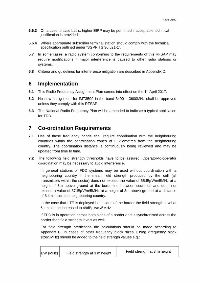
Page 9/190
5.6.3 On a case to case basis, higher EIRP may be permitted if acceptable technical justification is provided.
5.6.4 Where appropriate subscriber terminal station should comply with the technical specification outlined under “3GPP TS 36.521-1”.
5.7 In some cases, a radio system conforming to the requirements of this RFSAP may require modifications if major interference is caused to other radio stations or systems.
5.8 Criteria and guidelines for interference mitigation are described in Appendix D.
6 Implementation 6.1 This Radio Frequency Assignment Plan comes into effect on the 1st April 2017.
6.2 No new assignment for IMT3500 in the band 3400 – 3600MHz shall be approved unless they comply with this RFSAP.
6.3 The National Radio Frequency Plan will be amended to indicate a typical application for TDD.
7 Co-ordination Requirements 7.1 Use of these frequency bands shall require coordination with the neighbouring
countries within the coordination zones of 6 kilometres from the neighbouring country. The coordination distance is continuously being reviewed and may be updated from time to time.
7.2 The following field strength thresholds have to be assured. Operator-to-operator coordination may be necessary to avoid interference.
In general stations of FDD systems may be used without coordination with a neighbouring country if the mean field strength produced by the cell (all transmitters within the sector) does not exceed the value of 65dBV/m/5MHz at a height of 3m above ground at the borderline between countries and does not exceed a value of 37dBV/m/5MHz at a height of 3m above ground at a distance of 6 km inside the neighbouring country.
In the case that LTE is deployed both sides of the border the field strength level at 6 km can be increased to 49dBV/m/5MHz.
If TDD is in operation across both sides of a border and is synchronised across the border then field strength levels as well.
For field strength predictions the calculations should be made according to Appendix B. In cases of other frequency block sizes 10*log (frequency block size/5MHz) should be added to the field strength values e.g.:
BW (MHz) Field strength at 3 m height Field strength at 3 m height

Page 10/190
(general case) (LTE case)
5 MHz 65.0 dBµV/m/5MHz @0km 65.0 dBµV/m/5MHz @0km
37.0 dBµV/m/5MHz @6km 49.0 dBµV/m/5MHz @6km
10 MHz 68.0 dBµV/m/10MHz @0km 68.0 dBµV/m/10MHz @0km
40.0 dBµV/m/10MHz @6km 52.0 dBµV/m/10MHz @6km
15 MHz 69.8 dBµV/m/15MHz @0km 69.8 dBµV/m/15MHz @0km
41.8 dBµV/m/15MHz @6km 53.8 dBµV/m/15MHz @6km
20 MHz 71.0 dBµV/m/20MHz @0km 71.0 dBµV/m/20MHz @0km
43.0 dBµV/m/20MHz @6km 55.0 dBµV/m/20MHz @6km
If neighbouring administrations wish to agree on frequency coordination based on preferential frequencies, while ensuring a fair treatment of different operators within a country the Authority will add these within mutual agreements.
Stations of IMT systems may be operated without coordination if the mean field strength produced by the cell (all transmitters within the sector) does not exceed the value of 21dBµV/m/5MHz at 10% time, 50% of locations at 3 metres above ground level at the borderline.
7.3 Technical analysis may be conducted by the Authority before an assignment is issued according to Appendix B based on an extraction from ECC/REC(11)05.
7.4 Specific information regarding coordination may be found in Appendix C based on an extraction from ECC/REC(11)05.
7.5 In the event of any interference, the Authority will require affected parties to carry out coordination. In the event that the interference continues to be unresolved after 24 hours, the affected parties may refer the matter to the Authority for a resolution. The Authority will decide the necessary modifications and schedule of modifications to resolve the dispute. The Authority will be guided by the interference resolution process as shown in 0.
7.6 Assignment holders shall take full advantage of interference mitigation techniques such as antenna discrimination, tilt, polarization, frequency discrimination, shielding/blocking (introduce diffraction loss), site selection, and/or power control to facilitate the coordination of systems.
8 Assignment 8.1 Extended Approach
Any new assignment of frequency will take place according to the Extended Application Procedures in the applicable Radio Frequency Spectrum Regulations.

Page 11/190
9 Revocation 9.1 Existing radio frequency spectrum licences for the use of the band will be amended
as appropriate.
10 Radio Frequency Migration 10.1 Specific Procedure
Existing licensees to conform to the requirements of this RFSAP by the effective date.

Page 12/190
Appendix A National Radio Frequency Plan
ITU Region 1 allocation and footnotes
South African Allocation and footnotes
Typical Applications Comments
3400 – 3600MHz
FIXED
FIXED SATELLITE (space to Earth)
Mobile 5.430A
Radiolocation
5.431
3400-3600MHz
FIXED
MOBILE
5.430A, NF9
FWA (3400-3600MHz)
IMT3500 (3410-3490MHz)
IMT3500(3510-3590MHz)
PAIRED with 3510-3590 MHz
PAIRED with 3410-3490MHz

Page 13/190
Appendix B Propagation Model
The following methods are proposed for assessment of anticipated interference inside neighboring country based on established trigger values. Due to complexity of radio-wave propagation nature different methods are proposed to be considered by administrations and are included here for guidance purposes only. It should be noted that following methods provide theoretical predictions based on available terrain knowledge. It is practically impossible to recreate these methods with measurement procedures in the field. Therefore only some approximation of measurements could be used to check compliance with those methods based on practical measurement procedures. The details of such approximation are not included in this recommendation and should be negotiated between countries based on their radio monitoring practices.
Path specific model
Where appropriate detailed terrain data is available, the propagation model for interference field strength prediction is the latest version of ITU-R Rec. P.452, For the relevant transmitting terminal, predictions of path loss would be made at x km steps along radials of y km at z degree intervals17. The values for those receiver locations within the neighbouring country would be used to construct a histogram of path loss – and if more than 10% of predicted values exceed the threshold the station should be required to be coordinated.
Site General model
If it is not desirable to utilise detailed terrain height data for the propagation modelling in the border area, the basic model to be used to trigger coordination between administrations and to decide, if co-ordination is necessary, is ITU-R Rec. P.1546, “Method for point to area predictions for terrestrial services in the frequency range 30 to 3000 MHz”. This model is to be employed for 50% locations, 10% time and using a receiver height of 3m. For specific reception areas where terrain roughness adjustments for improved accuracy of field strength prediction are needed, administrations may use correction factors according to terrain irregularity and/or an averaged value of the TCA parameter in order to describe the roughness of the area on and around the coordination line.
Administrations and/or operators concerned may agree to deviate from the aforementioned model by mutual consent.
17 . Values for x, y, z and path specific field strength levels are to be agreed between the administrations concerned

Page 14/190
Area calculations
In the case where greater accuracy is required, administrations and operators may use the area calculation below. For calculations, all the pixels of a given geographical area to be agreed between the Administrations concerned in a neighbouring country are taken into consideration. For the relevant base station, predictions of path loss should be made for all the pixels of a given geographical area from a base station and at a receiver antenna height of 3m above ground.
For evaluation,
• only 10 percent of the number of geographical area between the borderline (including also the borderline) and the 6 km line itself inside the neighbouring country may be interfered by higher field strength than the trigger field strength value given for the borderline in Annex 1 and 2 at a height of 3 m above ground.
• only 10 percent of the number of geographical area between the 6 km (including also 6km line) and 12 km line inside the neighbouring country may be interfered by higher field strength than the trigger field strength value given for the 6 km line in Annex 1 and 2 at a height of 3 m above ground.
It is recommended that during area calculations not only detailed terrain data but also clutter data be taken into account. Use of correction factors for clutter is crucial in particular where the border area is ‘open’ or ‘quasi-open’ from the point of view of clutter or where the interfering base station is just a few kilometres from a borderline.
If the distance between a base station and a terrain point of a borderline is closer than or equal to 1 km, free space propagation model needs to be applied. Furthermore, if there is no terrain obstacle within the 1st Fresnel zone, also the free space propagation model should be applied.
If clutter data is not available, it is proposed to extend the usage of free space propagation model to a few kilometres, depending on the clutter situation in border areas.
For area type interference calculations, propagation models with path specific terrain correction factors are recommended (e.g. Recommendation ITU–R P.1546 with the terrain clearance angle correction factor TCA, HCM method with the terrain clearance angle correction factor or Recommendation ITU–R P.1812).
As to correction factors for clutters ‘open area’ and ‘quasi-open area’, 20 dB and 15 dB should be used respectively. Recommendation ITU–R P.1406 should be used if a finer selection of clutter is required.
It must be noted that terrain irregularity factor Δh is not recommended to be used in area calculations. Administrations and/or operators concerned may agree to deviate from the aforementioned models by mutual consent.

Page 15/190
Appendix C Coordination for IMT-Systems
PREFERENTIAL PHYSICAL-LAYER CELL IDENTITIES (PCI) FOR IMT-2000/LTE18
PCI co-ordination is only needed when channel centre frequencies are aligned independent of the channel bandwidth.
3GPP TS 36.211 defines 168 “unique physical-layer cell-identity groups” in §6.11, numbered 0…167, hereafter called “PCI groups”. Within each PCI group there are three separate PCIs giving 504 PCIs in total.
Administrations should agree on a repartition of these 504 PCI on an equitable basis when channel centre frequencies are aligned as shown in the Table below. It has to be noted that dividing the PCI groups or PCI’s is equivalent. Each country can use all PCI groups away from the border areas.
As shown in the table below, the PCI’s should be divided into 6 sub-sets containing each one sixth of the available PCI’s. Each country is allocated three sets (half of the PCI’s) in a bilateral case, and two sets (one third of the PCI’s) in a trilateral case.
Four types of countries are defined in a way such that no country will use the same code set as any one of its neighbours. The following lists describe the distribution of European countries:
Type country 1: BEL, CVA, CYP, CZE, DNK, E, FIN, GRC, IRL, ISL, LTU, MCO, SMR, SUI, SVN, UKR, AZE, SRB.
Type country 2: AND, BIH, BLR, BUL, D, EST, G, HNG, I, MDA, RUS (Exclave), GEO
Type country 3: ALB, AUT, F, HOL, HRV, POL, POR, ROU, RUS, S, MLT
Type country 4: LIE, LUX, LVA, MKD, MNE, NOR, SVK, TUR.
For each type of country, the following tables and figure describe the sharing of the PCI’s with its neighbouring countries, with the following conventions of writing:
Preferential PCI
non-preferential PCI
The 504 physical-layer cell-identities should be divided into the following 6 sub-sets when the carrier frequencies are aligned in border areas:
18 ECC/REC(11)05

Page 16/190
PCI Set A
Set B Set C Set D Set E Set F PCI
Set A Set B Set C Set D Set E Set F
Country 1 0..83
84..167 168..251 252..335
336..419 420..503 Country 2 0..83
84..16
7 168..25
1 252..335
336..4
19 420..503
Border 1-2 Border 2-1
Zone 1-2-3 Zone 2-3-1
Border 1-3 Border 2-3
Zone 1-2-4 Zone 2-1-4
Border 1-4 Border 2-4
Zone 1-3-4 Zone 2-3-4
PCI Set A Set B Set C Set D Set E Set F PCI
Set A Set B Set C Set D Set E Set F
Country 3 0..83
84..167 168..251 252..335
336..419 420..503 Country 4 0..83
84..16
7 168..25
1 252..335
336..4
19 420..503
Border 3-2 Border 4-1
Zone 3-1-2 Zone 4-1-2
Border 3-1 Border 4-2
Zone 3-1-4 Zone 4-2-3
Border 3-4 Border 4-3
Zone 3-2-4 Zone 4-3-1
Notes
1) All PCI’s are available in areas away from the border.
2) In certain specific cases (e.g. AUT/HRV) where the distance between two countries of the same type number is very small (< few 10s km), it may be necessary to address the situation in bi/multilateral coordination agreements as necessary, and may include further subdivision of the allocated codes in certain areas.

Page 17/190
GUIDANCE ON THE CONSIDERATION OF LTE RADIO PARAMETERS FOR USE IN BILATERAL AND MULTI LATERAL AGREEMENTS
This Annex is provided for guidance purposes for use in bi-lateral and multilateral discussions. For LTE, it may be beneficial to coordinate other radio parameters besides PCI in order to minimise deteriorating effects of uplink interference.
The parameters described in this Annex are usually optimised during LTE radio network planning of an operator’s network. The idea of optimisation is to plan the parameters taking into account specific correlation properties of the uplink control signals which enable more stable and predictable operation of the network. In the cross-border scenario the optimisation of parameters among neighbouring operators could provide better control of uplink interference. However because of the difference between intra-network and inter-network interference and due to limited experience in the LTE cross-border deployment it is difficult to assess the benefits of such optimisation. The following guidance provides the basis for operators to consider in border areas in case of high levels of uplink interference.
1. Demodulation Reference Signal (DM RS) coordination
Demodulation reference signals (DM RS) are transmitted in the uplink and used for channel estimation. There is a risk of intercell interference between neighbouring cells even in case of no frame synchronisation. That is why special measures for DM RS allocation between networks in neighbouring countries occupying the same channel may need to be applied. The case of partial channel overlap has not been studied but due to DM RS occupying resource blocks of separate users there is a risk of DM RS collisions between neighbouring networks when the subcarriers positions coincide (the frequency offset between central carriers of neighbouring networks is multiple of 300 kHz). Some minor benefits from DM RS coordination in these particular cases could be expected.
There are a number of possible approaches to the coordination of DM RS:
In basic planning procedure only 30 DM RS sequence groups with favourable correlation characteristics are available: {0…29}. In this case each cell could be assigned one of the 30 DM RS sequence groups providing cluster size of 30.
It is possible to extend each DM RS sequence group to generate up to 12 time shifted sequence groups by applying the cyclic shift parameter stated in 3GPP TS 36.211. For example each tri-sector site could be assigned one DM RS sequence group with each co-sited cell having its own cyclic shift of 2π/3 which provides cluster size 30 only with 10 DM RS sequence groups. The latter case corresponds well to the case of DM RS sequence groups repartition between neighbouring countries when only limited number of groups is available for network planning. The drawback of DM RS sequence group cyclic shift is a loss of orthogonally of DM RS due to fading channels which has been found only recently during first trials of LTE and caused throughput loss as well as time alignment problems.
Another approach for DM RS coordination is to implement dynamic DM RS sequence group allocation also called pseudo-random group hopping. In this method nearby
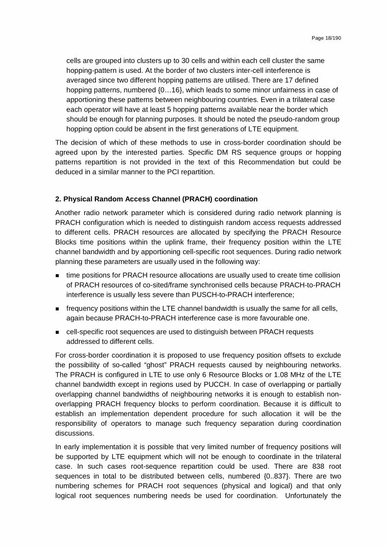
Page 18/190
cells are grouped into clusters up to 30 cells and within each cell cluster the same hopping-pattern is used. At the border of two clusters inter-cell interference is averaged since two different hopping patterns are utilised. There are 17 defined hopping patterns, numbered {0…16}, which leads to some minor unfairness in case of apportioning these patterns between neighbouring countries. Even in a trilateral case each operator will have at least 5 hopping patterns available near the border which should be enough for planning purposes. It should be noted the pseudo-random group hopping option could be absent in the first generations of LTE equipment.
The decision of which of these methods to use in cross-border coordination should be agreed upon by the interested parties. Specific DM RS sequence groups or hopping patterns repartition is not provided in the text of this Recommendation but could be deduced in a similar manner to the PCI repartition.
2. Physical Random Access Channel (PRACH) coordination
Another radio network parameter which is considered during radio network planning is PRACH configuration which is needed to distinguish random access requests addressed to different cells. PRACH resources are allocated by specifying the PRACH Resource Blocks time positions within the uplink frame, their frequency position within the LTE channel bandwidth and by apportioning cell-specific root sequences. During radio network planning these parameters are usually used in the following way:
time positions for PRACH resource allocations are usually used to create time collision of PRACH resources of co-sited/frame synchronised cells because PRACH-to-PRACH interference is usually less severe than PUSCH-to-PRACH interference;
frequency positions within the LTE channel bandwidth is usually the same for all cells, again because PRACH-to-PRACH interference case is more favourable one.
cell-specific root sequences are used to distinguish between PRACH requests addressed to different cells.
For cross-border coordination it is proposed to use frequency position offsets to exclude the possibility of so-called “ghost” PRACH requests caused by neighbouring networks. The PRACH is configured in LTE to use only 6 Resource Blocks or 1.08 MHz of the LTE channel bandwidth except in regions used by PUCCH. In case of overlapping or partially overlapping channel bandwidths of neighbouring networks it is enough to establish non-overlapping PRACH frequency blocks to perform coordination. Because it is difficult to establish an implementation dependent procedure for such allocation it will be the responsibility of operators to manage such frequency separation during coordination discussions.
In early implementation it is possible that very limited number of frequency positions will be supported by LTE equipment which will not be enough to coordinate in the trilateral case. In such cases root-sequence repartition could be used. There are 838 root sequences in total to be distributed between cells, numbered {0..837}. There are two numbering schemes for PRACH root sequences (physical and logical) and that only logical root sequences numbering needs be used for coordination. Unfortunately the

Page 19/190
process of root sequences planning doesn’t involve direct mapping of root sequences between cells because the number of root sequences needed for one cell is dependent on the cell range. The table showing such interdependency is presented below:
PRACH Configuration Number of root seq. per cell Cell Range (km)
1 1 0.7
2 2 1
3 2 1.4
4 2 2
5 2 2.5
6 3 3.4
7 3 4.3
8 4 5.4
9 5 7.3
10 6 9.7
11 8 12.1
12 10 15.8
13 13 22.7
14 22 38.7
15 32 58.7
0 64 118.8
Thus in the case of root sequence reparation it will be the responsibility of radio network planners to assign the correct number of root sequences in order to not to overlap with the root sequence ranges of other operators. It also should be noted that different root sequences have different cubic metrics and correlation properties which affect PRACH coverage performance and planning of so-called high-speed cells. For simplicity of cross-border coordination it is proposed to ignore these properties.
In summary it should be stipulated that frequency separation of PRACH resources should be used as the main coordination method. PRACH root sequences repartition should be avoided and used only in exceptional cases. Specific PRACH root sequences repartition is not provided in the text of this Recommendation but could be deduced in a similar manner to the PCI repartition.

Page 20/190
Appendix D Interference Resolution Process
When requesting coordination the relevant characteristics of the base station and the code or PCI group number should be forwarded to the Administration affected. All of the following characteristics should be included:
a) carrier frequency [MHz]
b) name of transmitter station
c) country of location of transmitter station
d) geographical coordinates [latitude, longitude]
e) effective antenna height [m]
f) antenna polarisation
g) antenna azimuth [deg]
h) antenna gain [dBi]
i) effective radiated power [dBW]
j) expected coverage zone or radius [km]
k) date of entry into service [month, year].
l) code group number used
m) antenna tilt [deg]
The Administration affected shall evaluate the request for coordination and shall within 30 days notify the result of the evaluation to the Administration requesting coordination. If in the course of the coordination procedure the Administration affected requires additional information, it may request such information.
If in the course of the coordination procedure an Administration may request additional information.
If no reply is received by the Administration requesting coordination within 30 days it may send a reminder to the Administration affected. An Administration not having responded within 30 days following communication of the reminder shall be deemed to have given its consent and the code co-ordination may be put into use with the characteristics given in the request for coordination.
The periods mentioned above may be extended by common consent.