radiation protection in dentistry - zodml protection in dentistry ncrp report no. 145 radiation...
TRANSCRIPT
145
RAD
IATION
PROTEC
TION
IN D
ENTISTRY
NCRP REPORT No. 145
RADIATION PROTECTION IN DENTISTRY
National Council on Radiation Protection and Measurements
N C R P
78987_AGS-NCRP_PB_CVR-R2 4/12/04 8:26 AM Page 1

NCRP REPORT No. 145
Radiation Protection in Dentistry
Recommendations of the NATIONAL COUNCIL ON RADIATION PROTECTION AND MEASUREMENTS
Issued December 31, 2003Revised October 12, 2004
National Council on Radiation Protection and Measurements7910 Woodmont Avenue, Suite 400 / Bethesda, MD 20814

LEGAL NOTICE This Report was prepared by the National Council on Radiation Protection and
Measurements (NCRP). The Council strives to provide accurate, complete and use-ful information in its documents. However, neither the NCRP, the members ofNCRP, other persons contributing to or assisting in the preparation of this Report,nor any person acting on the behalf of any of these parties: (a) makes any warrantyor representation, express or implied, with respect to the accuracy, completeness orusefulness of the information contained in this Report, or that the use of any infor-mation, method or process disclosed in this Report may not infringe on privatelyowned rights; or (b) assumes any liability with respect to the use of, or for damagesresulting from the use of any information, method or process disclosed in thisReport, under the Civil Rights Act of 1964, Section 701 et seq. as amended 42 U.S.C.Section 2000e et seq. (Title VII) or any other statutory or common law theory govern-ing liability.
Library of Congress Cataloging-in-Publication Data
Radiation protection in dentistry / National Council on RadiationProtection and Measurements. p. cm. -- (NCRP report ; no. 145)“December 2003.”“This Report was prepared by Scientific Committee 91-2 on RadiationProtection in Dentistry.”Includes bibliographical references and index.ISBN 0-929600-81-91. Teeth--Radiography--Safety measures. 2. Radiation--Safety
measures. I. National Council on Radiation Protection and Measurements.II. Series.RK309.R2725 2003617.6'07572--dc22
2003027119
Copyright © National Council on Radiation Protection and Measurements 2003
All rights reserved. This publication is protected by copyright. No part of this publica-tion may be reproduced in any form or by any means, including photocopying, or uti-
lized by any information storage and retrieval system without written permission from the copyright owner, except for brief quotation in critical articles or reviews.
[For detailed information on the availability of NCRP publications see page 174.]

iii
Preface
This Report was developed under the auspices of Scientific Com-mittee 91, the National Council on Radiation Protection and Mea-surements’ (NCRP) program area committee concerned withradiation protection in medicine. The Report provides radiation pro-tection guidance for the use of x rays in dental practice, includingadvice on shielding design for dental x-ray facilities. It supersedesNCRP Report No. 35, Dental X-Ray Protection, which was issued inMarch 1970.
The Report is dedicated to the memory of George W. Casarett,Ph.D., former Professor of Radiation Biology and Biophysics at theUniversity of Rochester School of Medicine and Dentistry, for hisenduring contributions to the NCRP, radiation biology, and radia-tion health sciences communities, and for his incomparable scien-tific, scholarly and graceful mentoring of dentists in the radiationsciences.
This Report was prepared by Scientific Committee 91-2 on Radi-ation Protection in Dentistry. Serving on Scientific Committee 91-2were:
Co-Chairmen
John W. Brand S. Julian GibbsUniversity of Detroit Mercy Vanderbilt University Medical
School of Dentistry CenterDetroit, Michigan Nashville, Tennessee
Members
Marc Edwards Alan G. LurieRadiation Oncology Associates University of Connecticut of Kansas City School of Dental MedicineOverland Park, Kansas Farmington, Connecticut
Jerald O. Katz Stuart C. WhiteUniversity of Missouri-Kansas University of California-
City School of Dentistry Los Angeles School of DentistryKansas City, Missouri Los Angeles, California
iv / PREFACE
ConsultantW. Doss McDavid
University of Texas Health Science CenterSan Antonio, Texas
NCRP SecretariatMarvin Rosenstein, Consultant, 2001-2003
Thomas M. Koval, Senior Staff Scientist, 1998-2000James A. Spahn, Jr., Senior Staff Scientist, 1995-1998
Cindy L. O’Brien, Managing Editor
The Council wishes to express its appreciation to the Committeemembers for the time and effort devoted to the preparation of thisReport.
Thomas S. TenfordePresident

v
Contents
Preface . . . . . . . . . . . . . . . . . . . . . . . . . . . . . . . . . . . . . . . . . . . . . iii
1. Introduction . . . . . . . . . . . . . . . . . . . . . . . . . . . . . . . . . . . . . 11.1 Purpose . . . . . . . . . . . . . . . . . . . . . . . . . . . . . . . . . . . . . . 11.2 Scope . . . . . . . . . . . . . . . . . . . . . . . . . . . . . . . . . . . . . . . . 21.3 Radiation Protection Philosophy . . . . . . . . . . . . . . . . . . 2
2. General Considerations . . . . . . . . . . . . . . . . . . . . . . . . . . . 72.1 Dose Limits . . . . . . . . . . . . . . . . . . . . . . . . . . . . . . . . . . . 82.2 Role of Dental Personnel in Radiation Protection . . . . 11
2.2.1 The Dentist . . . . . . . . . . . . . . . . . . . . . . . . . . . . . . 112.2.2 Auxiliary Personnel . . . . . . . . . . . . . . . . . . . . . . 122.2.3 The Qualified Expert . . . . . . . . . . . . . . . . . . . . . 12
3. Radiation Protection in Dental Facilities . . . . . . . . . . . 143.1 Protection of the Patient . . . . . . . . . . . . . . . . . . . . . . . . 14
3.1.1 Examination Extent and Frequency . . . . . . . . . 143.1.1.1 Symptomatic Patients . . . . . . . . . . . . . . 153.1.1.2 Asymptomatic Patients . . . . . . . . . . . . . 153.1.1.3 Administrative Radiographs . . . . . . . . 15
3.1.2 Radiation Exposure per Image . . . . . . . . . . . . . . 163.1.3 X-Ray Machines . . . . . . . . . . . . . . . . . . . . . . . . . 163.1.4 Examinations and Procedures . . . . . . . . . . . . . . 18
3.1.4.1 Intraoral Radiography . . . . . . . . . . . . . 183.1.4.1.1 Beam Energy . . . . . . . . . . . . 183.1.4.1.2 Position-Indicating Device . 183.1.4.1.3 Rectangular Collimation . . 193.1.4.1.4 Image Receptor . . . . . . . . . . 213.1.4.1.5 Patient Restraint . . . . . . . . 22
3.1.4.2 Extraoral Radiography . . . . . . . . . . . . . 223.1.4.2.1 Panoramic Radiography . . . 233.1.4.2.2 Cephalometric Radiography 24
3.1.4.3 Fluoroscopy . . . . . . . . . . . . . . . . . . . . . . 253.1.5 Film Processing . . . . . . . . . . . . . . . . . . . . . . . . . . 253.1.6 Digital Image Postprocessing . . . . . . . . . . . . . . . 25

vi / CONTENTS
3.1.7 Interpretation . . . . . . . . . . . . . . . . . . . . . . . . . . . 263.1.8 Leaded Aprons . . . . . . . . . . . . . . . . . . . . . . . . . . . 263.1.9 Thyroid Collars . . . . . . . . . . . . . . . . . . . . . . . . . . 27
3.2 Protection of the Operator . . . . . . . . . . . . . . . . . . . . . . . 273.2.1 Shielding Design . . . . . . . . . . . . . . . . . . . . . . . . . 28
3.2.1.1 Barriers . . . . . . . . . . . . . . . . . . . . . . . . . 283.2.1.2 Distance . . . . . . . . . . . . . . . . . . . . . . . . . 293.2.1.3 Position . . . . . . . . . . . . . . . . . . . . . . . . . . 29
3.2.2 Personal Dosimeters . . . . . . . . . . . . . . . . . . . . . . 293.3 Protection of the Public . . . . . . . . . . . . . . . . . . . . . . . . . . 303.4 Quality Assurance . . . . . . . . . . . . . . . . . . . . . . . . . . . . . . 31
3.4.1 Equipment Performance . . . . . . . . . . . . . . . . . . . 323.4.2 Film Processing . . . . . . . . . . . . . . . . . . . . . . . . . . 32
3.4.2.1 Sensitometry and Densitometry . . . . . . 323.4.2.2 Stepwedge . . . . . . . . . . . . . . . . . . . . . . . 333.4.2.3 Reference Film . . . . . . . . . . . . . . . . . . . . 34
3.4.3 Image Receptor . . . . . . . . . . . . . . . . . . . . . . . . . . 343.4.3.1 Film . . . . . . . . . . . . . . . . . . . . . . . . . . . . 343.4.3.2 Screen-Film Systems . . . . . . . . . . . . . . . 353.4.3.3 Digital-Imaging Systems . . . . . . . . . . . 35
3.4.4 Darkroom Integrity . . . . . . . . . . . . . . . . . . . . . . . 353.4.5 Leaded Aprons and Thyroid Collars . . . . . . . . . . 363.4.6 Documentation . . . . . . . . . . . . . . . . . . . . . . . . . . . 363.4.7 Suggested Quality-Assurance Procedures . . . . . 37
3.5 Training . . . . . . . . . . . . . . . . . . . . . . . . . . . . . . . . . . . . . . 373.6 Infection Control . . . . . . . . . . . . . . . . . . . . . . . . . . . . . . . 39
4. Role of Equipment Design . . . . . . . . . . . . . . . . . . . . . . . . . 404.1 Image Receptors . . . . . . . . . . . . . . . . . . . . . . . . . . . . . . . 404.2 Intraoral Radiography . . . . . . . . . . . . . . . . . . . . . . . . . . 41
4.2.1 Tube Head Stability . . . . . . . . . . . . . . . . . . . . . . . 414.2.2 Collimation . . . . . . . . . . . . . . . . . . . . . . . . . . . . . . 41
4.3 Panoramic Radiography . . . . . . . . . . . . . . . . . . . . . . . . . 414.4 Cephalometric Radiography . . . . . . . . . . . . . . . . . . . . . . 424.5 Multiple X-Ray Tube Installations . . . . . . . . . . . . . . . . . 42
5. Role of the Qualified Expert . . . . . . . . . . . . . . . . . . . . . . . 445.1 Shielding Design . . . . . . . . . . . . . . . . . . . . . . . . . . . . . . . 445.2 Equipment Surveys . . . . . . . . . . . . . . . . . . . . . . . . . . . . . 44
6. Conclusions . . . . . . . . . . . . . . . . . . . . . . . . . . . . . . . . . . . . . . 45

CONTENTS / vii
Appendix A. Radiography-Related Biohazards . . . . . . . . . 49A.1 Infection Control . . . . . . . . . . . . . . . . . . . . . . . . . . . . . . . 49
A.1.1 Facilities and Equipment . . . . . . . . . . . . . . . . . . 49A.1.2 Operative Procedures . . . . . . . . . . . . . . . . . . . . . 50A.1.3 Darkroom Procedures . . . . . . . . . . . . . . . . . . . . . 51
A.2 Waste Management . . . . . . . . . . . . . . . . . . . . . . . . . . . . 51A.3 Hazardous Chemicals . . . . . . . . . . . . . . . . . . . . . . . . . . . 53
Appendix B. Risk Assessment . . . . . . . . . . . . . . . . . . . . . . . . . 54B.1 Stochastic Effects . . . . . . . . . . . . . . . . . . . . . . . . . . . . . . 54
B.1.1 Cancer . . . . . . . . . . . . . . . . . . . . . . . . . . . . . . . . 54B.1.2 Organs and Tissues Exposed by Dental
X-Ray Procedures . . . . . . . . . . . . . . . . . . . . . . . . 58B.1.3 Genetic Effects . . . . . . . . . . . . . . . . . . . . . . . . . . 62B.1.4 Effective Dose . . . . . . . . . . . . . . . . . . . . . . . . . . . 63
B.2 Deterministic Effects . . . . . . . . . . . . . . . . . . . . . . . . . . . 66B.2.1 Effects in the Embryo and Fetus . . . . . . . . . . . . 66B.2.2 Exposure to the Embryo and Fetus in Dental
X-Ray Procedures . . . . . . . . . . . . . . . . . . . . . . . . 67
Appendix C. Evaluation of Radiation Safety Program Performance and Equipment Performance . . . . . . . . . 68C.1 Methods of Radiation Protection in Dentistry . . . . . . . 68
C.1.1 Categories of Individuals to be Protected . . . . . 69C.1.1.1 Occupationally-Exposed Individuals . . 69C.1.1.2 Nonoccupationally-Exposed
Individuals . . . . . . . . . . . . . . . . . . . . . . . 70C.1.1.3 Patients . . . . . . . . . . . . . . . . . . . . . . . . . 70
C.1.2 Protection by Equipment Design . . . . . . . . . . . . 71C.1.3 Protection by Facility Design . . . . . . . . . . . . . . . 72C.1.4 Protection by Operating Procedure Design . . . . 73
C.2 Radiation Protection Surveys, Documentation and Reporting . . . . . . . . . . . . . . . . . . . . . . . . . . . . . . . . . . . . . 73C.2.1 Facility Surveys . . . . . . . . . . . . . . . . . . . . . . . . . . 74C.2.2 Equipment Surveys . . . . . . . . . . . . . . . . . . . . . . . 75
C.2.2.1 Intraoral Equipment . . . . . . . . . . . . . . . 75C.2.2.2 Panoramic Equipment . . . . . . . . . . . . . 76
C.2.3 Administrative Controls . . . . . . . . . . . . . . . . . . . 76C.3 Radiation Monitoring in Dentistry . . . . . . . . . . . . . . . . 76
C.3.1 Facility Monitoring . . . . . . . . . . . . . . . . . . . . . . . 76C.3.2 Personal Monitoring . . . . . . . . . . . . . . . . . . . . . . 77
C.4 Conclusion . . . . . . . . . . . . . . . . . . . . . . . . . . . . . . . . . . . . 79

viii / CONTENTS
Appendix D. Selection Criteria . . . . . . . . . . . . . . . . . . . . . . . . 80
Appendix E. Image Receptors . . . . . . . . . . . . . . . . . . . . . . . . . 85E.1 Characteristics . . . . . . . . . . . . . . . . . . . . . . . . . . . . . . . . 85E.2 Intraoral Film . . . . . . . . . . . . . . . . . . . . . . . . . . . . . . . . . 85E.3 Screen Films and Intensifying Screens . . . . . . . . . . . . . 86E.4 Direct Digital Radiography . . . . . . . . . . . . . . . . . . . . . . . 87
E.4.1 Charge-Coupled Device Arrays . . . . . . . . . . . . . . 87E.4.2 Photostimuable Storage Phosphor Receptors . . 88E.4.3 Features of Direct Digital Radiography . . . . . . . 88
Appendix F. Shielding Design for Dental Facilities . . . . . . 89F.1 General Principles . . . . . . . . . . . . . . . . . . . . . . . . . . . . . . 89F.2 Barrier Thickness Calculations . . . . . . . . . . . . . . . . . . . 92
F.2.1 Determining Protective Barrier Requirements . 92F.2.1.1 Operating Potential (Kilovolt Peak) . . . 93F.2.1.2 Workload . . . . . . . . . . . . . . . . . . . . . . . . 96F.2.1.3 Use Factor . . . . . . . . . . . . . . . . . . . . . . . 98
F.2.1.3.1 Intraoral Radiography . . . . 98F.2.1.3.2 Panoramic Radiography . . 101
F.2.1.4 Occupancy Factor . . . . . . . . . . . . . . . . 101F.2.1.5 X-Ray Leakage Characteristics . . . . . 101
F.2.2 Shielding Design Goals . . . . . . . . . . . . . . . . . . . 102F.3 Formalism of Shielding Calculations . . . . . . . . . . . . . . 102
F.3.1 Primary Radiation . . . . . . . . . . . . . . . . . . . . . . . 106F.3.2 Secondary Radiation . . . . . . . . . . . . . . . . . . . . . 113
F.3.2.1 Scattered Radiation . . . . . . . . . . . . . . . 114F.3.2.2 Leakage Radiation . . . . . . . . . . . . . . . . 114
F.4 Examples of Barrier Calculations . . . . . . . . . . . . . . . . 115F.4.1 Example of a Primary Barrier Exact
Calculation . . . . . . . . . . . . . . . . . . . . . . . . . . . . . 115F.4.2 Example of an Open Space Design
Calculation . . . . . . . . . . . . . . . . . . . . . . . . . . . . . 116F.5 Examples of Approximate Barrier Thickness
Calculations . . . . . . . . . . . . . . . . . . . . . . . . . . . . . . . . . . 118F.5.1 Shielding Tables for Various Barrier
Materials . . . . . . . . . . . . . . . . . . . . . . . . . . . . . . 118F.5.2 Use of Simplified Barrier Thickness Tables . . . 119
F.5.2.1 Example I . . . . . . . . . . . . . . . . . . . . . . . 119F.5.2.2 Example II . . . . . . . . . . . . . . . . . . . . . . 133F.5.2.3 Example III . . . . . . . . . . . . . . . . . . . . . 134
F.6 Summary . . . . . . . . . . . . . . . . . . . . . . . . . . . . . . . . . . . . 135

CONTENTS / ix
Appendix G. Radiation Quantities and Units . . . . . . . . . . 136
Glossary . . . . . . . . . . . . . . . . . . . . . . . . . . . . . . . . . . . . . . . . . . . 138
References . . . . . . . . . . . . . . . . . . . . . . . . . . . . . . . . . . . . . . . . . 150
The NCRP . . . . . . . . . . . . . . . . . . . . . . . . . . . . . . . . . . . . . . . . . 165
NCRP Publications . . . . . . . . . . . . . . . . . . . . . . . . . . . . . . . . . 174
Index . . . . . . . . . . . . . . . . . . . . . . . . . . . . . . . . . . . . . . . . . . . . . . 185

1
1. Introduction
Radiology is an essential component of dental diagnosis. Avail-able data clearly show that ionizing radiation, if delivered in suffi-cient doses, may produce biological damage. However, it is not clearthat radiation in doses required for dental radiography presentsany risk. Neither is it clear that these small doses are free of risk.The practitioner may reasonably expect that the health benefit tothe patient from dental radiographic examination will outweighany potential risk from radiation exposure provided that:
• the dental radiographic examination is clinically indicatedand justified
• the technique is optimized to ensure high-quality diagnosticimages
• the principles outlined in this Report are followed to mini-mize exposure to the patient, staff and the public
Office design, equipment, and procedures that minimize patientexposure will also reduce exposure to the operator and the public.Additional measures, however, may be required to ensure thatdoses to operators and the public are within limits established byregulatory bodies. Doses to all should be kept as low as reasonablyachievable, with economic and social factors being taken intoaccount (i.e., the ALARA principle) (NCRP, 1990). For operatorsand the public, the ALARA principle applies to further reduction ofdoses that are already below regulatory limits. The concept may beextended to patients for whom no regulatory limits exist. It statesthat all reasonable efforts should be made to reduce or eliminateavoidable radiation exposure, so long as scarce resources are notunduly diverted from other societal needs that may be more critical(NCRP, 1998).
1.1 Purpose
The objective of this Report is to present methods and proce-dures for radiation protection in the dental office. The goals are:(1) to eliminate unnecessary radiation exposure to the patient, i.e.,

2 / 1. INTRODUCTION
radiation not necessary to produce optimal quality radiographs;and (2) to ensure that exposures to office staff and the public arewithin recommended limits and meet the ALARA principle. ThisReport makes a number of recommendations for the dentist toachieve these goals.
1.2 Scope
This Report provides guidelines for radiation protection in theuse of x rays in dental practice. It replaces the National Council onRadiation Protection and Measurements’ (NCRP) Report No. 35(NCRP, 1970) in its entirety. It presents recommendations regard-ing performance and optimal use of dental x-ray equipment, as wellas recommendations for radiation protection surveys and monitor-ing of personnel. Sections are included for the specific guidance ofdentists, their clinical associates, and qualified experts conductingradiation protection surveys, calibration procedures, equipmentperformance evaluations, and determining facility shielding andlayout designs. Also included is guidance for equipment designers,manufacturers, and service personnel. Basic guidance for dentistsand their office staff is contained in the body; technical details areprovided in the appendices. Certain aspects of radiation protectionunique to dental radiology (e.g., the impact of infection control mea-sures on radiation protection) are included (Appendix A).
Since the target audience may not have easy access to relateddocuments, this Report is intended to be a stand-alone document,providing sufficient background and guidance for most applica-tions. Additional details may be found in other reports of the NCRP(1976; 1988; 1989a; 1989b; 1990; 1992; 1993a; 1993b; 1997; 1998;2000; 2001; in press). Further, the intent is to focus on those radio-graphic procedures commonly performed in dental facilities, espe-cially intraoral, panoramic and cephalometric dental radiographicequipment and techniques. Except as otherwise specified, the rec-ommendations in this Report apply to these procedures. Other pro-cedures of oral and maxillofacial radiology that are not generallypracticed in the dental office, and that require more sophisticatedequipment, are subject to the requirements and recommendationsfor medical radiology (NCRP, 1989a; 1989b; 2000) and will not bespecifically addressed in this Report.
1.3 Radiation Protection Philosophy
Biological effects of ionizing radiation fall into two classes:deterministic and stochastic (Appendix B). Deterministic effects

1.3 RADIATION PROTECTION PHILOSOPHY / 3
occur in all individuals who receive a high dose, i.e., exceeding somethreshold. Examples of these effects are acute radiation sickness,cataract, and epilation. Their severity is proportional to dose,implying the presence of a threshold dose below which no clini-cally-significant effects occur. Stochastic effects, such as cancer, areall-or-nothing effects. That is, either a radiation-induced canceroccurs or it does not; its severity is not dose dependent. The proba-bility of its occurrence is proportional to dose, implying the absenceof a threshold. The basic goal of radiation protection is to preventin exposed individuals the occurrence of deterministic effects andto reduce the potential for stochastic effects to an acceptable levelwhen benefits of that exposure are considered (NCRP, 1993a).Achievement of this goal requires two interrelated activities:(1) efforts to ensure that no individual receives a dose greater thanthe recommended limit and (2) efforts to ensure that doses areALARA. In most applications, ALARA is simply the continuation ofgood radiation protection programs and practices that have tradi-tionally been effective in keeping the average of individual expo-sures of monitored workers well below the limits. Cost-benefitanalysis is applied to measures taken to achieve ALARA goals. Foreach source or type of radiation exposure, it is determined whetherthe benefits outweigh the costs. Second, the relation of cost to ben-efit from the reduction or elimination of that exposure is evaluated.Frequently costs and benefits are stated in disparate units. Costsmay be in units such as adverse biological effects or economicexpenditure. Benefits may be in units such as disease detected orlives saved. Three principles provide the basis for all actions takenfor purposes of radiation protection. They are:
1. Justification: The benefit of radiation exposure outweighsany accompanying risk.
2. Optimization: Total exposure remains as low as reason-ably achievable, with economic and social factors takeninto account (the ALARA principle).
3. Dose limitation: Dose limits are applied to each individualto ensure that no one is exposed to an unacceptably highrisk.
All three of these principles are applied to evaluation of occupa-tional and public exposure. The first two apply to exposure ofpatients. However, no dose limit is established for diagnostic ortherapeutic exposure of patients. The primary objective is to ensurethat the health benefit overrides the risk to the patient from thatexposure.

4 / 1. INTRODUCTION
NCRP has established recommended dose limits for occupa-tional and public exposure (Table 1.1) (NCRP, 1993a). Limits havebeen set below the estimated human threshold doses for determin-istic effects. NCRP assumes that for radiation protection purposes,the risk of stochastic effects is proportional to dose without thresh-old, throughout the range of dose and dose rates of importance inroutine radiation protection (NCRP, 1993a). This principle wasused to set dose limits for occupationally-exposed individuals suchthat estimated risks of stochastic effects are no greater than risksof occupational injury in other vocations that are generallyregarded as safe (Table 1.2).
TABLE 1.1—Recommended dose limits (NCRP, 1993a).a
Basis Dose Limit
Occupational
Stochastic effects 50 mSv annual effective dose10 mSv × age (y) cumulative effective dose
Deterministiceffects
150 mSv annual equivalent dose to lens of eye500 mSv annual equivalent dose to skin,
hands and feet
Public
Stochastic effects 1 mSv annual effective dose for continuousor frequent exposure
5 mSv annual effective dose for infrequentexposure
Deterministic effects
15 mSv annual equivalent dose to lens of eye50 mSv annual equivalent dose to skin,
hands and feet
Embryo and fetus 0.5 mSv equivalent dose in a month fromoccupational exposure of the mother oncepregnancy is known
aThe appropriate dose limits for adult students (i.e., age 18 or older)in dental, dental hygiene, and dental assisting educational programsdepend on whether the educational entity classifies the student asoccupationally exposed or not. Additional guidance for radiation protec-tion practices for educational institutions is given in NCRP (1966).Dose limits for students under 18 y of age are given in NCRP (1993a),and correspond to the limits for members of the public.

1.3 RADIATION PROTECTION PHILOSOPHY / 5
Two terms used in this Report have a special mean-ing as indicated by the use of italics:
1. Shall and shall not are used to indicatethat adherence to the recommendation is consid-ered necessary to meet accepted standards ofprotection.
2. Should and should not are used to indicate a pru-dent practice to which exceptions may occasion-ally be made in appropriate circumstances.
The use of ionizing radiation in the healing arts is a well-regulated activity in the United States. The federal governmenthas established a performance standard that controls manufactureand installation of x-ray generating equipment designed for clinicaluse (FDA, 1995). The states (or other political jurisdictions) haveimplemented regulations that govern users, including dentists.These regulations pertain to design of facilities, especially radia-tion shielding, as well as use and maintenance of equipment.
TABLE 1.2—Fatal accident rates, United States, 1991 (NCRP, 1993a).
Industry GroupFatality Rate
(per 10,000 workers per year)
Trade 0.4
Manufacturing 0.4
Service 0.4
Government 0.9
Radiation 0.2 – 2.0a
Transportation, public utilities 2.2
Construction 3.1
Mining, quarrying 4.3
Agriculture 4.4
All groups 0.9
aLifetime fatal cancer risk from each year’s exposure (assuming arisk coefficient of 4 × 10⁻² Sv
–1, and occupational effective doses to anaverage worker between 0.5 and 5 mSv y
–1). Estimated using the lin-ear nonthreshold model. Actual fatal cancer risk for radiation may bemore, less, or even zero. Entries for other industries are taken fromactuarial data for fatal work-related accidents.

6 / 1. INTRODUCTION
Dentists shall use x-ray equipment and procedures ina manner that ensures compliance with both the rec-ommendations in this Report and the requirementsof their state or political jurisdictions. When thereare discrepancies between these recommendationsand legal requirements, the more rigorous shall takeprecedence.

7
2. General Considerations
All persons are exposed to radiation in their daily lives (NCRP,1987a; 1987b; 1987c; 1989c; 1989d). NCRP has estimated the meaneffective dose equivalent from all sources in the United States as3.6 mSv y
–1 (Figure 2.1). Approximately 3 mSv of this arises from
Fig. 2.1. U.S. average annual effective dose equivalent (per capita)from all sources in 1987. The total (rounded) is 3.6 mSv y
–1. About 3 mSvof this is from naturally-occurring sources: 2 mSv from inhalation ofradon and its radioactive decay products; 0.27 mSv from cosmic radiation;0.28 mSv from radioactive materials in our surrounding earth, buildingmaterials, etc.; and 0.39 mSv from radioactive sources within our bodies.Most man-made radiation comes from diagnostic exposure in the healingarts (~0.5 mSv), with small quantities from occupational sources,consumer products such as smoke detectors or luminous watch dials, andmiscellaneous sources such as cosmic radiation exposure during air travelas a passenger (NCRP, 1987b).

8 / 2. GENERAL CONSIDERATIONS
naturally-occurring sources; these sources have been present sincethe beginning of the Earth. Only 0.6 mSv comes from man-madesources, most of which is from diagnostic exposure in the healingarts. Recent data from Switzerland indicate that dental x rays con-tribute approximately one percent of the total dose from the heal-ing arts (Aroua et al., 2002). Thus, dental radiation is a minorcontributor to total population burden. However, appropriate mea-sures are necessary to maintain dental radiation exposuresALARA.
2.1 Dose Limits
The Council has recommended annual and cumulative doselimits for individuals from occupational radiation exposure, andseparate annual dose limits for members of the public from sourcesof man-made radiation (Table 1.1) (NCRP, 1993a). The dose limitsdo not apply to diagnostic or therapeutic exposure of the patient inthe healing arts.
The cumulative limit for occupational dose is more restrictivethan the annual limit. For example, an individual who begins atage 18 to receive annual occupational doses of 50 mSv will in 4 yreceive 200 mSv, approaching the cumulative limit of 220 mSv atage 22. At that point, occupational exposure to that individualwould be confined by the cumulative, not the annual limit. That is,the individual would then be limited to a cumulative dose at theaverage rate of 10 mSv y
–1, with a maximum rate of 50 mSv in any1 y. Occupationally-exposed individuals may be monitored forwork-related radiation exposure and the duties of any individualwho approaches the annual or cumulative limit may be changed sothe limit is not exceeded.
Since members of the public do not wear monitors, facilities aredesigned, operated and monitored such that no individual canreceive a dose in excess of the recommended limit.
Published data indicate that average dental occupationalexposures are usually only a small fraction of the limit and are lessthan most other workers in the healing arts (Table 2.1) (Kumazawaet al., 1984). Occupational exposures have been declining (Fig-ure 2.2) over recent decades in workers in both the healing arts ingeneral and dentistry in particular (HSE, 1998; Kumazawa et al.,1984; UNSCEAR, 2000). It seems reasonable to conclude that nodental personnel will receive occupational exposures exceeding thelimit unless there are problems with facility design, equipmentperformance, or operating procedures.

2.1 DOSE LIMITS / 9
No individual shall be permitted to receive an occu-pational effective dose in excess of 50 mSv in any 1 y.The numerical value of the individual worker’s life-time occupational effective dose shall be limited to10 mSv times the value of his or her age in years.
Occupational equivalent dose shall not exceed0.5 mSv in a month to the embryo or fetus for preg-nant individuals, once pregnancy is known.
Mean nonoccupational effective dose to frequently orcontinuously exposed members of the public shallnot exceed 1 mSv y
–1 (excluding doses from naturalbackground and medical care); infrequently exposedmembers of the public shall not be exposed to effec-tive doses greater than 5 mSv in any year.
TABLE 2.1—Occupational doses in the healing arts, United States, 1980.a
OccupationalSubgroup
Number of WorkersMean Annual
Whole-Body Dose
(mSv)
Totalb Exposedc Totalb Exposedc
Hospital 126,000 86,000 1.4 2.0
Medical offices
155,000 87,000 1.0 1.8
Dental 259,000 82,000 0.2 0.7
Podiatry 8,000 3,000 0.1 0.3
Chiropractic 15,000 6,000 0.3 0.8
Veterinary 21,000 12,000 0.6 1.1
Total 584,000 276,000 0.7 1.5
aKumazawa et al. (1984).bAll workers with potential occupational exposure.cWorkers who received a measurable dose in any monitoring period
during the year.

10 / 2. GENERAL CONSIDERATIONS
Dental facility design, x-ray equipment performanceand operating procedures shall be such that no indi-vidual exposure exceeds these recommended doselimits.
Facility design, x-ray equipment performance andoperating procedures should be established to main-tain patient, occupational and public exposures aslow as reasonably achievable, economic and socialfactors being taken into account (the ALARAprinciple).
The ALARA principle is an optimization of radiation protectionconcept applied to each facility. Thus it imposes no numeric limita-tions of effective dose below the established effective dose limits(Table 1.1). The goal is that the entire radiology operation bedesigned to reduce radiation exposure to the minimum achievable
Fig. 2.2. Decline in mean occupational doses over recent decades, forworkers in all healing arts combined and dentistry. United States data at5 y intervals from 1960 to 1980 plus that projected for 1985 were reportedas dosimeter readings (Kumazawa et al., 1984). World estimates from1975 to 1995 were reported as effective doses and are plotted at each 5 yinterval (UNSCEAR, 2000). Dental workers do not generally wear leadedaprons, so differences between dosimeter readings and effective dosesmay be small (Appendix C).

2.2 ROLE OF DENTAL PERSONNEL IN RADIATION PROTECTION / 11
for the specific facility without incurring undue cost or compromis-ing patient care. That is, effective doses achieved through applica-tion of the ALARA principle may vary by facility or even by specificx-ray machine in a given facility. In dentistry, the application of theALARA principle is expected to reduce effective doses to individu-als well below the applicable dose limits.
2.2 Role of Dental Personnel in Radiation Protection
ALARA requires optimizing the practices of all dental personnelthat are involved in prescription, exposure, processing, evaluationand interpretation of dental radiographs. This Section describesthe roles of each.
2.2.1 The Dentist
In most dental facilities, the dentist in charge is responsible forthe design and conduct of the radiation protection program (NRPB,2001). In large facilities, such as dental educational institutions,the authority and responsibility for design and oversight of theradiation protection program may be delegated to a specificemployee with special expertise in the field. This individual isdesignated the radiation safety officer. The dentist in charge, inconsultation with the radiation safety officer (if that person issomeone other than the dentist) and with a qualified expert,is responsible for implementing the radiation protection program,which includes (NCRP, 1990; 1998):
• establishing, reviewing and documenting radiation protec-tion procedures
• instructing staff in radiation protection• implementing radiation surveys and recording results and
corrective actions• establishing the monitoring of personnel, if required• ensuring that all radiation protection features are func-
tional and the required warning signs are posted• implementing and monitoring the ALARA principle• implementing and documenting quality-assurance procedures
The dentist (or, in some facilities, the designatedradiation safety officer) shall establish a radiationprotection program as outlined above. The dentistshall seek guidance of a qualified expert in thisactivity.

12 / 2. GENERAL CONSIDERATIONS
The dentist is qualified by education and licensure to prescribeand perform radiographic examinations and to process, evaluateand interpret the images produced.
All radiographic examinations shall be performedonly on direct prescription of the dentist or physi-cian. These procedures shall be prescribed only afterconduct of a clinical history and physical examina-tion of the patient, and determination of a reasonableexpectation of a health benefit to the patient.
2.2.2 Auxiliary Personnel
In most dental facilities the staff involved in radiologic proce-dures consists of registered dental hygienists and of dental assis-tants who may or may not be certified. Registered hygienists andcertified assistants are trained and credentialed to perform radio-logic exposures, process the images and evaluate them for quality(NRPB, 2001). In some states noncertified assistants may becredentialed for these procedures upon completion of approvedtraining.
Dental radiographic exposures shall be performedonly by dentists or by legally qualified and creden-tialed auxiliary personnel. Opportunities should beprovided for auxiliary personnel to attend appropri-ate continuing education courses.
2.2.3 The Qualified Expert
This individual is qualified by education and experience to per-form advanced or complex procedures in radiation protection thatgenerally are beyond the capabilities of most dental personnel(NRPB, 2001). These procedures include facility design to provideadequate shielding for protection of the occupationally exposed andthe public, inspection and evaluation of performance of x-ray equip-ment, or evaluation and recommendation of radiation protectionprograms (including the ALARA principle). Generally possessingan advanced degree in medical physics, medical health physics, ora similar field, this individual is usually certified by the AmericanBoard of Radiology, the American Board of Medical Physics, Amer-ican Board of Health Physics, or equivalent. Care must be taken toensure that the qualified expert’s credentials include knowledge

2.2 ROLE OF DENTAL PERSONNEL IN RADIATION PROTECTION / 13
and familiarity with dental radiologic practices. Some otherwisehighly qualified experts may have little experience in dental radio-logical practices (Michel and Zimmerman, 1999). Some statescredential or license these individuals. The principal responsibilityof this person is to serve as a consultant to the dentist.
The dentist or designer shall obtain guidance of aqualified expert in the design of dental facilities andestablishment of radiation protection policies andprocedures.

14
3. Radiation Protection in Dental Facilities
Radiation protection recommendations specific to the dentalfacility are provided in this Section. Technical details are found inthe appendices.
3.1 Protection of the Patient
Potential health benefits to patients from dental x-ray exposurepreclude establishment of specific and meaningful dose limits forpatients. Thus the specific goal of protection of the patient shouldbe to obtain the required clinical information while avoiding unnec-essary patient exposure.
3.1.1 Examination Extent and Frequency
Elimination of unnecessary radiographic examinations is a veryeffective measure for avoiding unnecessary patient exposure. Pro-cedures are outlined in the following sections for eliminatingunnecessary examinations for both symptomatic patients seekingurgent care and asymptomatic patients scheduled for routine orcontinuing dental care.
A clear procedure for reducing the extent and frequency of den-tal radiographic examinations needs to be followed when a patienttransfers or is referred from one dentist to another. Modern digitalimaging and electronic transfer facilitates exchange of informationamong dentists and other health care providers.
For each new or referred patient, the dentist shallmake a good faith attempt to obtain recent, pertinentradiographs from the patient’s previous dentist.
Radiographic examinations shall be performed onlywhen indicated by patient history, physical examina-tion by the dentist, or laboratory findings.

3.1 PROTECTION OF THE PATIENT / 15
3.1.1.1 Symptomatic Patients. When symptomatic patients areseen, the dentist is obligated to provide care to relieve those symp-toms and, when possible, eliminate their cause. Radiographsrequired for that treatment are fully justified, but additional non-contributory radiographs are not. For example, a full-mouthintraoral study is not warranted for emergency treatment of a sin-gle painful tooth. However, if treatment of that painful tooth is thefirst step in comprehensive dental care, then those radiographsrequired for that comprehensive care are justified.
For symptomatic patients, radiographic examinationshall be limited to those images required for diagno-sis and planned treatment (local or comprehensive)of current disease.
3.1.1.2 Asymptomatic Patients. Maintenance of oral health inasymptomatic new patients or those returning for periodicre-examination without clear signs and symptoms of oral diseasemay require radiographs. Selection criteria that will aid the dentistin selecting and prescribing radiographic examination of thesepatients have been published (Appendix D) (Joseph, 1987;Matteson, 1997; Matteson et al., 1991). These criteria recommendthat dental radiographs be prescribed only when the patient’s his-tory and physical findings suggest a reasonable expectation thatradiographic examination will produce clinically useful informa-tion.
For asymptomatic patients, the extent of radio-graphic examination of new patients, and the fre-quency and extent for return patients, should adhereto published selection criteria.
3.1.1.3 Administrative Radiographs. Radiographs are occasion-ally requested, usually by outside agencies, for purposes other thanhealth. Examples include requests from third-party paymentagencies for proof of treatment or from regulatory boards to deter-mine competence of the practitioner. In some institutions dental ordental auxiliary students have been required to perform oralradiographic examinations on other students for the sole purposeof learning the technique. Other methods (such as photographsfor treatment documentation or image receptor and tube-head placement for radiologic technique training) that do notrequire exposure to x rays are generally available for providing thisinformation.

16 / 3. RADIATION PROTECTION IN DENTAL FACILITIES
Administrative use of radiation to provide informa-tion not related to health of the patient shall not bepermitted. Students shall not be permitted to per-form radiographic exposures of patients, other stu-dents, or volunteers solely for purposes of theireducation or licensure.
3.1.2 Radiation Exposure per Image
Patient exposure per intraoral film, measured at skin entry, hasbeen reduced significantly since the early days of dental radiology(Figure 3.1). These reductions have been accomplished by improve-ments in x-ray equipment, operating procedures, and films. Thetotal number of films exposed per year in the United States hasincreased at a rate faster than growth of the population (FDA,1973; NCHCT, 1982; UNSCEAR, 2000). Continuing efforts areneeded to provide further reduction of exposure per image. Amethod to achieve this goal is the use of a diagnostic reference level.A diagnostic reference level is a patient dose-related quantity perx-ray procedure or image that, if consistently exceeded in clinicalpractice, should elicit investigation and efforts for improved patientdose management (ICRP, 1996a; Napier, 1999). Suggested values ofdiagnostic reference levels at skin entry for common dental x-rayprojections (bitewings and cephalometric) have been published(CRCPD, 2003; Gray et al., in press; NRPB, 1999). The diagnosticreference levels in the United States are expressed as entrance skinexposure (in milliroentgens) or entrance air kerma (in milligray),and for bitewings are a function of film speed (i.e., D-, E- or F-speedfilm) and operating potential (i.e., 50 to 100 kVp) (CRCPD, 2003)(see Glossary for explanation of these quantities). A number ofstates have established diagnostic reference levels that are applica-ble for a given state (CRCPD, 2003). It is the responsibility of thedentist to choose the fastest available image receptor (direct-exposure film, screen film, or digital) (Appendix E) consistent withthe imaging requirements of each specific examination.
3.1.3 X-Ray Machines
All x-ray machines need to meet the design specifications in Sec-tion 4 and all requirements of the jurisdiction in which they arelocated. Equipment certified to conform to the federal performancestandard (FDA, 1995) will generally meet these requirements.Equipment of recent manufacture (especially that manufactured in

3.1 PROTECTION OF THE PATIENT / 17
Europe) also conforms to international standards (IEC, 1994;NRPB, 2001). Section 4 outlines parameters of equipment design;it provides guidance to manufacturers and may be useful to thedentist in selecting and purchasing x-ray machines. Portable x-rayequipment is intended for use with debilitated patients whosephysical condition prevents transporting them to fixed radio-graphic facilities. It is not the purpose of portable x-ray equipmentto provide for convenience of the operator or of healthy patients.
Personnel responsible for purchase and operationof dental x-ray equipment shall ensure that suchequipment meets or exceeds all applicable govern-mental requirements and regulations, plus the designspecifications summarized in Section 4. In addition,the equipment should conform to internationalstandards.
Portable x-ray machines shall not be used when fixedinstallations are available and patients’ conditionspermit their use.
Fig. 3.1. Relative exposure at skin entry for intraoral radiographs,1920 to 2000. Arrows indicate introduction of faster films (ANSI speedgroups A, B, C, D, E, and F, as indicated). The exposure required forF-speed film is approximately one percent of that required for the firstdental films (Farman and Farman, 2000).

18 / 3. RADIATION PROTECTION IN DENTAL FACILITIES
3.1.4 Examinations and Procedures
The general requirements and recommendations in this Reportapply to all dental radiologic examinations and procedures. ThisSection, however, presents additional recommendations specific forparticular radiographic examinations.
3.1.4.1 Intraoral Radiography. Dental intraoral radiographs andchest radiographs have been the most common diagnostic x-rayprocedures in the United States (Brown et al., 1980; FDA, 1973;Mettler, 1987). In both cases, patient dose per image is small; how-ever, the number of such procedures performed annually requiresdiligence in optimizing the radiation exposure from procedures sothat unnecessary exposure is avoided.
3.1.4.1.1 Beam energy. Dental x-ray machines have been marketedfor intraoral radiography with operating potentials ranging from40 to more than 100 kVp (kilovolt peak). However, the U.S. federalperformance standard now requires that low-kVp (less than 60)intraoral dental x-ray machines be heavily filtered such that effec-tive beam energies will approach that of 60 kVp machines (FDA,1995). Published data show no significant relationship betweenoperating potential and effective dose to the patient with beamsranging from 70 to 90 kVp (Gibbs et al., 1988a). These data applyspecifically to half-wave rectified dental x-ray machines. Similarbeam energy spectra are produced by constant-potential machinesoperating some 10 kV below the kVp of these conventionalmachines. There is little to be gained from operating potentialshigher than 80 kVp. Many contemporary machines operate at afixed operating potential which, if in the 60 to 80 kVp range, is gen-erally acceptable.
The operating potential of dental x-ray machinesshall not be less than 50 kVp and should not be lessthan 60 kVp. Also, the operating potential shall notbe more than 100 kVp and should not be more than80 kVp.
3.1.4.1.2 Position-indicating device. Pointed cones have been com-monly used as position-indicating devices for aiming x-ray beamsfor intraoral radiography. However, they are not suitable for posi-tive beam-receptor alignment (Section 4) and have been largelyreplaced with open-end parallel-wall devices that are eithercircular or rectangular in cross-section. These devices are not

3.1 PROTECTION OF THE PATIENT / 19
collimators. Thus, their inside dimensions are equal to or slightlylarger than the dimensions of the beam at the position-indicatingdevice tip. The position-indicating device may be lined with metalto absorb scattered radiation arising from the collimator and filter.
Position-indicating devices shall be open-endeddevices with provision for attenuation of scatteredradiation arising from the collimator or filter.
Short source-to-skin distances (or source-to-image receptordistances) produce unfavorable dose distributions (van Aken andvan der Linden, 1966). They may degrade the sharpness of theimages, and also produce excessive magnification or distortion ofthe image, sometimes limiting anatomic coverage.
Source-to-image receptor distance for intraoral radi-ography shall not be less than 20 cm and should notbe less than 40 cm.
3.1.4.1.3 Rectangular collimation. Existing requirements and rec-ommendations require that all medical and dental diagnostic x-rayprocedures except intraoral radiography be performed with thebeam collimated to the area of clinical interest; in no case can it belarger than the image receptor (FDA, 1995). Positive beam-receptoralignment is required to ensure that all exposed tissue is recordedon the image. However, requirements and recommendations todate have permitted circular beams for intraoral radiographywhose area, measured in the plane of the receptor, may be up to fivetimes the area of the receptor. Published data show that rectangu-lar collimation of the beam to the size of the image receptor reducesthe tissue volume exposed (Figure 3.2). This would reduce the effec-tive dose to the patient by a factor of four to five, without adverseinfluence on image quality (Freeman and Brand, 1994; Gibbs,2000; Gibbs et al., 1988a; Underhill et al., 1988). Effective devicesfor positive beam-receptor alignment for periapical radiographyhave been commercially available at nominal cost for many years,providing rectangular collimation for routine clinical use.
Beam-receptor alignment devices for conventional interproxi-mal (bitewing) radiography remain only marginally effective. Con-ventional bitewing technique, with the long axis of the standardintraoral image receptor horizontal, requires that the teeth be in orvery near occlusal contact during exposure, in order to providerequired anatomic coverage including not only the crowns of theteeth but also the crestal alveolar bone. Two approaches have beendevised: (1) paper bite tabs, thin enough to provide for sufficient

20 / 3. RA
DIA
TIO
N P
RO
TE
CT
ION
IN D
EN
TA
L FA
CIL
ITIE
S
Fig. 3.2. Isodose curves calculated for full-mouth intraoral examinations obtained at 80 kVp using optimum exposures forD-speed film. Lines without numeric annotations indicate skin surface and internal hard tissue surfaces. Numericannotations indicate absorbed dose in microgray (1,000 µGy = 1 mGy). For example, the tissues contained within the contourlabeled 5,000 receive an absorbed dose of at least 5 mGy (5,000 µGy). (A) Transverse section through the occlusal plane, 7 cmround beams. Note that the teeth receive absorbed doses of at least 12 mGy, and all tissues anterior to the cervical spinereceive at least 5 mGy. (B) Same plane with rectangular collimation. Areas contained within each isodose contour are smallerthan in A. Absorbed dose is generally confined to the facial area, with posterior regions receiving absorbed doses no greaterthan 1 mGy (Gibbs et al., 1987).

3.1 PROTECTION OF THE PATIENT / 21
anatomic coverage but not sufficiently rigid and (2) plastic bitetabs, sufficiently rigid but too thick to allow desired anatomic cov-erage. This problem can be solved by placing the bitewing imagereceptor with the long axis oriented vertically.
Alternatively, a new image receptor size could be developed toprovide bitewing images that include crestal bone, with the longaxis of the image receptor oriented horizontally. In other words,rectangular collimation of the x-ray beam is available for periapicaland vertical bitewing radiography; future developments may makeit practical for other projections, including occlusal and horizontalbitewing. Perfect rectangular collimation, with the beam dimen-sions exactly equal to those of the image receptor, is difficult if notimpossible to achieve. Tolerance in beam dimensions is allowable toreduce required precision of beam-receptor alignment to an accom-plishable level.
Rectangular collimation of the x-ray beam shall beroutinely used for periapical radiography. Eachdimension of the beam, measured in the plane of theimage receptor, should not exceed the dimension ofthe image receptor by more than two percent of thesource-to-image receptor distance. Similar collima-tion should be used, when feasible, for interproximal(bitewing) radiography. Anatomy or the inability ofoccasional specific patients to cooperate, includingsome children, may make rectangular collimationand beam-receptor alignment awkward or impossiblefor some projections. The requirement may berelaxed in these rare cases.
Positive beam-receptor alignment allows more freedom inpatient positioning. Many dentists prefer to recline the patientfully, rotating the head left or right, and maintaining the beamnear vertical.
3.1.4.1.4 Image receptor. Since the mid-1950s the most commonimage receptor (Appendix E) for intraoral radiography in theUnited States has been direct-exposure film of American NationalStandards Institute (ANSI) Speed Group D (Goren et al., 1989;Platin et al., 1998). Faster films, ANSI Speed Group E, were intro-duced in the early 1980s, with improved versions coming in themid-1990s. These faster films have been widely used in Europe(Svenson and Petersson, 1995; Svenson et al., 1996). Publisheddata show that these faster films provide for patient dose reduc-tions of up to 50 percent. However, early E-speed films exhibited

22 / 3. RADIATION PROTECTION IN DENTAL FACILITIES
decreased contrast and higher sensitivity to processing conditionsthan was found with D-speed films (Diehl et al., 1986; Thunthy andWeinberg, 1982). These problems have been corrected and currentE-speed film can be used with no degradation of diagnostic infor-mation (Conover et al., 1995; Hintze et al., 1994; 1996; Kitagawaet al., 1995; Nakfoor and Brooks, 1992; Price, 1995; Svenson et al.,1997a; Tamburus and Lavrador, 1997; Tjelmeland et al., 1998).Digital image receptors with speeds similar to or faster thanE-speed film are available. Intraoral films of speed group F arecommercially available. Initial data suggest suitability of thesefilms for routine use (Farman and Farman, 2000; Ludlow et al.,2001; Thunthy, 2000). If these results are confirmed, these filmsshould be considered for routine use. Future developments arelikely to include even faster films and digital receptors.
Image receptors of speeds slower than ANSI SpeedGroup E films shall not be used for intraoral radiog-raphy. Faster receptors should be evaluated andadopted if found acceptable.
3.1.4.1.5 Patient restraint. It may be necessary in some cases thatuncooperative patients be restrained during exposure or that theimage receptor be held in place by hand. A member of the patient’sfamily (or other caregiver) provides this restraint or receptor retention.
Occupationally-exposed personnel shall not restrainuncooperative patients or hold the image receptor inplace during an x-ray exposure. Members of the pub-lic who restrain patients or hold image receptors dur-ing exposure shall be provided with shielding, e.g.,leaded aprons, gloves.
3.1.4.2 Extraoral Radiography. Regulations, recommendationsand procedures (NCRP, 1989a) from medical radiology, includingpositive beam-receptor alignment and collimation of the beam tothe area of clinical interest, apply to extraoral dental projections. Afew of these projections are peculiar to dental radiology. High-speedscreen-film systems or digital image receptors meet the require-ments of spatial and contrast resolution for these images.
The fastest imaging system consistent with the imag-ing task shall be used for all extraoral dental radio-graphic projections. High-speed (400 or greater) rareearth screen-film systems or digital-imaging systemsof equivalent or greater speed shall be used.

3.1 PROTECTION OF THE PATIENT / 23
Some digital-imaging systems are slower than the recom-mended 400 regular speed. These slower systems are notrecommended for routine use.
3.1.4.2.1 Panoramic radiography. Panoramic images providecurved-plane tomograms of the teeth and jaws. The method iswidely used in dental practice (Bohay et al., 1995a; 1995b; 1998;Callen, 1994; Friedland, 1998; Kogon et al., 1995). The majoradvantages are rapid acquisition of a single image encompassingthe entire dental arches and their supporting structures, withoutthe possibility of occasional discomfort of intraoral image receptorplacement and minimal problems of infection control. Effectivedose to the patient for a single panoramic image is approximatelyequal to that from four intraoral images, both using state-of-the-arttechnique (Gibbs, 2000). However, there are significant disadvan-tages that have radiation protection implications and need to berecognized by the dentist. Vertical image magnification is indepen-dent of horizontal magnification. The degree of magnification var-ies with position in the dental arch. This image distortion varieswith anatomic area in a given patient and from patient to patientusing the same panoramic x-ray machine. Further, repeat imagesof the same patient may show differing distortion because of slightdifferences in patient positioning. Image resolution is limited bythe imperfect movement of source and image receptor required forthe tomographic technique. Resolution is poorer than the dentist isaccustomed to seeing from intraoral images and is likely to be inad-equate for definitive diagnosis of incipient caries, beginning peri-apical lesions, or marginal periodontal disease (Flint et al., 1998;Rumberg et al., 1996).
The zone of sharp focus is limited and varies with manufacturerand model. It typically is designed to accommodate average adults;a few machines allow adjustment to patient dimensions. Patientpositioning is critical and varies with manufacturer and model.Some use biteblocks that, if reusable, may present problems ofinfection control. Some machines allow only limited adjustmentof beam parameters for factors such as image receptor speed andpatient thickness. Older machines were designed for use withmedium-speed calcium tungstate screen-film systems. In somecases the required reduction in x-ray output for use withhigh-speed rare-earth screen-film systems may be accomplishedonly by electronic modifications (prohibited by the federal perfor-mance standard) or by addition of filtration. Added filtration,unless compensated by lower kVp, hardens the beam spectrum,resulting in decreased image contrast. The dentist needs to be

24 / 3. RADIATION PROTECTION IN DENTAL FACILITIES
aware of these limitations in selecting and maintaining panoramicequipment or prescribing panoramic examinations. Otherwise, thelimited diagnostic information obtained from the panoramic imagemay necessitate additional imaging. Periapical views alone may beadequate.
Panoramic x-ray machines shall be capable of operat-ing at exposures appropriate for high-speed (400 orgreater) rare-earth screen-film systems or digitalimage receptors of equivalent or greater speed.
3.1.4.2.2 Cephalometric radiography. The cephalometric techniqueprovides reproducible radiographs of the facial structures. Theprincipal application is evaluation of growth and development, asfor orthodontic treatment. The equipment provides for positioning(and repositioning) of the patient together with alignment of beam,subject and image receptor. The source-to-skin distance is typically150 cm or more, providing minimal geometric distortion in theimage. It is frequently useful for the cephalometric image to showbony anatomy of the cranial base and facial skeleton plus thesoft-tissue outline of facial contours, requiring image receptorsof wide latitude. Filters that reduce exposure to the soft tissues ofthe facial profile have been used for this purpose (Freedman andMatteson, 1976). In some circumstances these filters have beenplaced at the image receptor instead of at the x-ray source.
Only the fastest screen-film system compatible withimaging requirements shall be used for the cephalo-metric image. Filters for imaging the soft tissues ofthe facial profile together with the facial skeletonshall be placed at the x-ray source rather than at theimage receptor.
The cephalometric x-ray beam can be collimated to the area ofclinical interest, which is almost always smaller than the dimen-sions of the image receptor. Cephalometric analysis of the usuallateral image does not require visualization of the dome of thecalvarium or any structures posterior to the occipital condyles orinferior to the hyoid. Posterior-anterior cephalometric projectionsare also used; they also need not record structures superior to thecranial base or inferior to the hyoid. Practitioners need to remem-ber that all structures recorded on the image need to be interpretedfor evidence of disease or injury as well as for cephalometricanalysis.

3.1 PROTECTION OF THE PATIENT / 25
The x-ray beam for cephalometric radiography shallbe collimated to the area of clinical interest.
3.1.4.3 Fluoroscopy. Real-time imaging, or fluoroscopy, is usefulonly for imaging changes in structures. Its use should be limited tothose tasks requiring real-time imaging, such as the evaluation ofmoving anatomic structures (such as the temporomandibular joint)or the injection of radiographic contrast fluids (such as for sialo-graphy or temporomandibular joint arthrography). Fluoroscopyrequires electronic image intensification and video display tominimize patient exposure; this equipment is expensive and notusually found in dental facilities. Further, dental x-ray machinesare not generally capable of providing the required continuousradiation exposure.
Fluoroscopy shall not be used for static imaging indental radiography.
3.1.5 Film Processing
Maintenance of image quality and minimum patient exposuredepend on proper film processing. Film manufacturers prescribe orrecommend processing chemicals and procedures matched to thefilm emulsion. Like all chemical processes, the time required forimage development to progress to completion is inversely propor-tional to temperature. Therefore, development time is adjusted forthe temperature of the solution. This time-temperature method ofensuring complete development may be achieved by either manualor automatic processing. When development is incomplete, x-rayexposure is increased to provide useful image density. The combi-nation of increased exposure and incomplete development resultsin not only needless overexposure of the patient but also decreasedimage contrast.
Dental radiographic films shall be developed accord-ing to the film manufacturer’s instructions, using thetime-temperature method and recommended chemis-try or its equivalent. Sight developing shall not beused.
3.1.6 Digital Image Postprocessing
A major advantage of digital imaging is the ability to alterimage properties after acquisition. It is possible to make certain

26 / 3. RADIATION PROTECTION IN DENTAL FACILITIES
features more obvious by procedures such as adjustment of imagedensity and contrast (technically called window level and width); orimage reversal, or exchange of the “negative” radiographic imagefor a “positive” like a photographic print. These procedures maycompensate for over- or underexposure, eliminating the need forretake of a poorly exposed image. However, these procedures allowthe injudicious use of routine over- or underexposure, each withundesirable consequences. Overexposures needlessly increasepatient dose without significant benefit. Underexposure results indecreased signal-to-noise ratio (Appendix E), resulting in loss ofdiagnostic information as the image becomes “grainy” or “snowy.”Further, uninformed or injudicious use of these procedures mayproduce the appearance of disease where it does not exist (false pos-itive) or absence of disease where it exists (false negative) (Tsanget al., 1999).
Radiographic techniques for digital imaging shallbe adjusted for the minimum patient dose requiredto produce a signal-to-noise ratio sufficient toprovide image quality to meet the purpose of theexamination.
3.1.7 Interpretation
Unnecessary exposure in radiography may be due to inadequateevaluation and interpretation, resulting in diagnostic errors andunproductive radiation exposure. For maximum diagnostic yieldat minimum exposure, image evaluation and interpretation isbest carried out in a quiet atmosphere, free from distractions(Wuehrmann, 1970). Perception of image details has been shown tobe maximum when the illuminated surface of the view box not cov-ered with films and opaque film mounts is masked with opaquematerial to eliminate glare, variable luminance of the view-boxlamp is available, room illumination is reduced to the level of thedisplayed films, and a magnifier is used.
3.1.8 Leaded Aprons
Leaded aprons for patients were first recommended in dentistrymany years ago when dental x-ray equipment was much lesssophisticated and films much slower than current standards. Theyprovided a quick fix for the poorly collimated and unfiltered dentalx-ray beams of the era. Gonadal (or whole-body) doses from theseearly full-mouth examinations, reported as large as 50 mGy(Budowsky et al., 1956), could be reduced substantially by leaded

3.2 PROTECTION OF THE OPERATOR / 27
aprons. Gonadal doses from current panoramic or full-mouthintraoral examinations using state-of-the-art technology and pro-cedures do not exceed 5 µGy (5 × 10⁻³ mGy) (White, 1992). A signif-icant portion of this gonadal dose results from scattered radiationarising within the patient’s body. Leaded aprons do not signifi-cantly reduce these doses. Technological and procedural improve-ments have eliminated the requirement for the leaded apron,provided all other recommendations of this Report are rigorouslyfollowed (NRPB, 2001). However, some patients have come toexpect the apron and may request that it be used. Its use remainsa prudent but not essential practice.
The use of leaded aprons on patients shall not berequired if all other recommendations in this Reportare rigorously followed. However, if under excep-tional circumstances any of these recommendationsare not implemented in a specific case, then theleaded apron should be used.
3.1.9 Thyroid Collars
The thyroid gland, especially in children, is among the most sen-sitive organs to radiation-induced tumors, both benign and malig-nant (Appendix B). Even with optimum techniques, the primarydental x-ray beam may still pass near and occasionally through thegland. If the x-ray beam is properly collimated to the size ofthe image receptor or area of clinical interest, and exposure of thegland is still unavoidable, any attempt to shield the gland wouldinterfere with the production of a clinically-useful image. However,in those occasional uncooperative patients for whom rectangularcollimation and positive beam-receptor alignment cannot beachieved for intraoral radiographs, then thyroid shielding mayreduce dose to the gland without interfering with image production(NRPB, 2001).
Thyroid shielding shall be provided for children, andshould be provided for adults, when it will not inter-fere with the examination.
3.2 Protection of the Operator
Equipment and procedures that reduce patient exposure willalso reduce exposure of the operator and the environment. Addi-tional measures, however, will further reduce occupational andpublic exposure without affecting patient dose or image quality.

28 / 3. RADIATION PROTECTION IN DENTAL FACILITIES
3.2.1 Shielding Design
Attention to office layout and shielding design provide conve-nient methods for implementing the ALARA principle. Shieldingdoes not necessarily mean lead-lined x-ray rooms. Normal buildingmaterials may be sufficient in most cases. Expert guidance canprovide effective shielding design at nominal incremental cost(Appendix F), with protection by barriers, distance from x-raysource, and operator position.
Shielding design by a qualified expert shall be pro-vided for all new or remodeled dental facilities. Whena conventional building structure does not provideadequate shielding, the shielding shall be increasedby providing greater thickness of building materialsor by adding lead, gypsum wallboard, concrete, steelor other suitable material. Adequacy of shieldingshall be determined by calculation and checked bysurvey measurements.
It is in the economic best interest of the dentist to obtain shield-ing design by a qualified expert at the design stage. For a new orremodeled facility, proper shielding design can usually provideradiation protection to meet shielding design goals (Appendix F) atlittle or no incremental construction cost. However, if measure-ments after construction is finished indicate that these require-ments are not met, the cost of retrofitting might be considerable.
Several commercial and noncommercial software packages areavailable to perform shielding calculations. Such software may beemployed only if the user is fully aware of its underlying assump-tions and limitations. In particular, the leakage radiation charac-teristics of dental x-ray housings may be significantly differentfrom that of medical diagnostic x-ray housings. Uninformed use ofsoftware cannot be substituted for consultation with a qualifiedexpert.
3.2.1.1 Barriers. It is a fundamental principle of radiation protec-tion that no one other than the patient undergoing the procedure ispermitted in the room at the time of radiation exposure. Fixed bar-riers, generally walls, provide the most economical, effective andconvenient means of excluding office staff from the primary x-raybeam as it exits the patient or from radiation scattered from thepatient or other objects in the primary beam.

3.2 PROTECTION OF THE OPERATOR / 29
Shielding design for new offices shall provide protec-tive barriers for the operator. The barriers shall beconstructed so operators can maintain visual contactand communication with patients throughout theprocedures.
3.2.1.2 Distance. In some existing facilities, design precludes useof a protective barrier.
In the absence of a barrier in an existing facility, theoperator shall remain at least 2 m from the tube headduring exposure. If the 2 m distance cannot be main-tained, then a barrier shall be provided.
3.2.1.3 Position. If the facility design requires that the operator bein the room at the time of exposure, then the operator shouldbe positioned not only at maximum distance (at least 2 m) fromthe tube head, but also at the location of minimum exposure (Fig-ure 3.3). Maximum exposure will generally be in the primary beamas it exits the patient. Maximum scattered radiation will be back-wards, i.e., 90 to 180 degrees from the primary beam as it enters thepatient. Generally the position of minimum exposure will be at45 degrees from the primary beam as it exits the patient (de Haanand van Aken, 1990).
3.2.2 Personal Dosimeters
Monitoring of individual occupational exposures is generallyrequired if it can be reasonably expected that any dental staff mem-ber will receive a significant dose. NCRP (1998) recommends provi-sion of monitors to all personnel who are likely to receive aneffective dose greater than 1 mSv y
–1. It needs to be emphasizedthat this recommendation concerns effective dose, which is gener-ally much less than monitor readings (Appendix C). The mostrecent available data (Table 2.1) indicate that the average annualoccupational dose in dentistry in the United States in 1980 was0.2 mSv (Kumazawa et al., 1984). Few dental workers receivedmore than 1 mSv and 68 percent received exposures below thethreshold of detection.
World data for the period 1990 to 1994 show a mean annualoccupational dose of 0.06 mSv for dental workers (UNSCEAR,2000). These data suggest that dental personnel are not expectedto receive occupational exposures greater than the recommendedthreshold for monitoring of 1 mSv y
–1. However, the limit applicable

30 / 3. RADIATION PROTECTION IN DENTAL FACILITIES
to pregnant workers of 0.5 mSv equivalent dose to the fetus permonth once pregnancy is known, suggest that personal dosimetrymay be a prudent practice for those workers. Current regulationsrequire that dosimeters be obtained from services accredited foraccuracy and reproducibility. These services distribute dosimeterpackets regularly; the facility returns the packets to the serviceafter use (generally monthly or quarterly) for readout and report.
Provision of personal dosimeters for external expo-sure measurement should be considered for workerswho are likely to receive an annual effective dose inexcess of 1 mSv.
Personal dosimeters shall be provided for knownpregnant occupationally-exposed personnel.
3.3 Protection of the Public
For shielding design purposes, the public includes all individu-als who are in uncontrolled areas such as reception rooms, other
Fig. 3.3. Operator exposure as a function of position in room relativeto patient and primary beam. View from above for a left molar bitewing.The heavy line in the polar coordinate plot indicates dose by its distancefrom the center of the plot. Maximum dose is in the exit beam.The recommended positions for minimum exposures (crosses) are at45 degrees from the exit beam. Note that most scattered radiation isbackward (de Haan and van Aken, 1990).

3.4 QUALITY ASSURANCE / 31
treatment rooms or in adjacent corridors in the building within oroutside of the dental facility (NCRP, 2000; in press). The popular“open design” dental facility, which places two or more treatmentchairs in a single room, may present problems.
A patient in the room during diagnostic exposure ofanother patient shall be treated as a member of thepublic. When portable x-ray machines are used, allindividuals in the environs (e.g., other patients, theirfamilies, etc.) shall be protected as members of thepublic.
Based on NCRP (1993a) and the International Commission onRadiological Protection (ICRP, 1991) recommendations for theannual limit on effective dose to a member of the general public,shielding designs need to limit exposure to all individuals in uncon-trolled areas to an effective dose that does not exceed 1 mSv y
–1.After a review of the application of the guidance in NCRP (1993a)to medical (and dental) facilities, NCRP has concluded that a suit-able source constraint for shielding individual members of the pub-lic in or near such facilities is an effective dose of 1 mSv in any year(NCRP, in press). This recommendation can be achieved with aweekly shielding design goal of 0.02 mGy air kerma (i.e., an annualair-kerma value of 1 mGy for uncontrolled areas) (Appendix F).
New dental facilities shall be designed such that noindividual member of the public will receive an effec-tive dose in excess of 1 mSv annually.
3.4 Quality Assurance
Radiation exposure to patient, operator and the public can bereduced by minimizing the need for repeat exposures because ofinadequate image quality (NRPB, 2001). The term “quality assur-ance” describes a program for periodic assessment of the perfor-mance of all parts of the radiologic procedure (NCRP, 1988;Valachovic et al., 1981). In addition to determination of x-raymachine performance by a qualified expert (Appendix C), film pro-cessing chemistry and procedures, image receptor performancecharacteristics, and darkroom integrity need to be evaluated atappropriate intervals (AADR, 1983; NCHCT, 1981; Valachovicet al., 1981). These routine quality-assurance procedures can beperformed by properly-trained dental office staff.

32 / 3. RADIATION PROTECTION IN DENTAL FACILITIES
A written protocol for periodic quality assuranceshall be developed and implemented for each x-raymachine, image receptor system, and processor ordarkroom.
3.4.1 Equipment Performance
Dental x-ray machines are inspected at regular intervals toensure that they are functioning within specifications. Theseinspections are performed by a qualified expert.
All new dental x-ray installations and existing instal-lations not previously surveyed shall have a radia-tion protection survey performed by, or underthe direction of, a qualified expert. Resurveys shallbe performed at regular intervals thereafter. Theresurvey interval should not exceed 4 y. In addition,a resurvey shall be made after any change in theinstallation, workload, or operating conditions thatmight significantly increase occupational or pub-lic exposure (including x-ray machine service orrepair that could affect the x-ray machine outputor performance).
3.4.2 Film Processing
Darkroom solutions are subject to gradual deterioration. Thedeterioration may go unnoticed as it becomes severe enough todegrade image quality. Daily determinations are required to pre-vent this degradation in a typical dental facility.
Darkroom chemistry and each film processor used inthe facility shall be evaluated daily for performance,i.e., constancy of optical density and contrast, andoverall quality of the resulting films.
3.4.2.1 Sensitometry and Densitometry. The most sensitive andrigorous method of darkroom quality assurance requires the use ofa sensitometer, a precise optical device to expose a film to producea defined pattern of optical densities in the processed film. Thesedensities are then measured with a densitometer, and compared tothe densities in a similarly-exposed film previously processed infresh solutions under ideal conditions. A daily log is maintained;any change indicates a problem with processing, either develop-ment time or temperature or contaminated solutions. This method

3.4 QUALITY ASSURANCE / 33
requires additional equipment but only a few minutes of operatortime to execute. It is highly recommended for the busy facility, butsimpler, less costly methods may be adequate for average dentaloffices.
3.4.2.2 Stepwedge. A standard radiographic film exposed throughan aluminum stepwedge (Figure 3.4) to a defined x-ray exposuremay be substituted for the sensitometrically-exposed film. Thestepwedge may be purchased at nominal cost, fabricated by amachine shop, or fabricated in the office using lead foil backingsfrom dental film packets (Valachovic et al., 1981). Overall size ofthe stepwedge should be similar to that of a standard intraoralfilm. It is made to resemble stairs. Each step of an aluminum step-wedge is 1 mm thick and about 3 to 4 mm wide. There should be atleast six steps. Exposure parameters, including x-ray machine set-tings and exposure geometry are reproduced precisely for eachexposure. The structure on which the film is placed will providebackscattered radiation that will affect film density. Thus the filmand source are placed in the same position on the same structurefor each exposure. The processed film is then compared visuallywith a reference film identically exposed and processed in fresh
Fig. 3.4. Machined aluminum stepwedge, placed over an intraoral filmpacket. Each step is 1 mm in depth and 3 mm wide. An effectivestepwedge can be constructed from a stack of layers of aluminum or leadfoil. It is used for exposing test films for quality assurance.

34 / 3. RADIATION PROTECTION IN DENTAL FACILITIES
solutions under ideal conditions. Devices that facilitate this processare commercially available at modest cost. A reproducible changeof one step or more in density, which is readily detectable visuallyand readily confirmed by repeating the test, should signal the needfor corrective action. The change in density may be the result ofeither a different x-ray exposure or differences in processing. Dark-room problems are more likely and should be corrected first. Thismethod is less sensitive than sensitometry and densitometry butshould suffice for many dental facilities.
3.4.2.3 Reference Film. Use of a properly exposed and processedintraoral film as a reference has been proposed as another methodof quality assurance (AADR, 1983; Valachovic et al., 1981). Whenusing this method, a high-quality film is attached to a corner of theview box. Subsequent clinical films can then be compared with thisreference film. This method is not as sensitive or reliable as a sen-sitometry and densitometry or a stepwedge, and is not recom-mended for routine use. In rare circumstances it may be used as astopgap measure, usually in facilities with very low radiographicworkload (fewer than 10 intraoral films per week).
3.4.3 Image Receptor
Radiographic films, screen-film systems, and digital imagereceptors constitute an important part of radiology. Their perfor-mance is tested periodically to ensure that they function accordingto specifications.
3.4.3.1 Film. Unexposed film may become “fogged” by gradualchemical deterioration, which is temperature dependent and there-fore may be slowed by storing film in a refrigerator. Alternatively,stray light or x rays may produce an increase in density of exposedor unexposed film. Exposure to certain chemicals, heat or pressuremay produce fog or other artifacts. These artifacts may be detectedby processing and evaluating an unexposed film. Evaluation is bestperformed with a densitometer but may be approximated by visualcomparison of the current film with an unfogged film from a newbox and processed in fresh solutions.
Each type of film used in the facility shall be evalu-ated for fog and artifacts monthly and each time anew box or batch of film is opened. When excessivefog is identified, the affected box or batch of filmshall be discarded or returned to the vendor forreplacement.

3.4 QUALITY ASSURANCE / 35
3.4.3.2 Screen-Film Systems. Both cassettes and screens mayacquire defects during normal use. Integrity of cassettes is deter-mined by visual inspection and by processing of an unexposed filmthat has been in the cassette for at least 1 h while the cassette isexposed to normal room illumination. Light leaks from the cassettewill appear as dark streaks on the film. Screens are evaluated visu-ally for surface defects such as scratches or fingerprints. Screenmaintenance requires periodic cleaning, following the manufac-turer’s instructions. Poor screen-film contact leads to unsharpnessin images. Screen-film contact and uniformity of response are bestevaluated by exposing a film (in its cassette) overlaid with a pieceof copper test screen. Visual inspection of the processed film forsharpness and uniformity of the image can assess performance ofthe imaging system.
Screen-film cassettes, including screens, shall bevisually evaluated after any accident (such as drop-ping) for integrity and performance. Tests forscreen-film contact should be performed every sixmonths. Any defective items shall be promptlyrepaired or replaced.
3.4.3.3 Digital-Imaging Systems. Procedures for evaluating theperformance of digital-imaging systems are quite different fromthose used with film or screen-film image receptors. By usingappropriately designed phantoms and software, image qualityaspects such as resolution, contrast, signal-to-noise ratio, and con-trast-to-noise ratio may be measured directly. However, therequired standards, apparatus and software for dental systems donot currently exist. These limitations are important factors whenconsidering the purchase of digital-imaging systems.
3.4.4 Darkroom Integrity
Each darkroom is evaluated for light leaks and safelight perfor-mance. A “coin test” is performed by placing an unexposedunwrapped intraoral film at a normal working position and puttinga coin upon it. After a time equivalent to a normal darkroom proce-dure (such as processing films from a typical clinical procedure),the film is processed. An image of the coin indicates a problem witheither light leaks or the safelight. Repeating the procedure withthe safelight off will determine which was the source of the prob-lem. These tests are performed monthly or following a change in

36 / 3. RADIATION PROTECTION IN DENTAL FACILITIES
safelight filter or lamp. Direct exposure films have different spec-tral sensitivities from those used with screens; a safelight filterappropriate for one may not be adequate for the other.
Daylight loaders are commonly used with automatic dental filmprocessors, eliminating the need for the darkroom. These systemsprovide light-tight boxes attached to the processor loading areas.Each box contains a port for placing exposed films (still in theirwrappers or cassettes) in the box, ports for inserting the hands sothe operator may manipulate films in the box, and a viewing portwith a filter similar to the safelight filter. The safelight filter isdesigned for use in a darkroom with low-level illumination; it maynot provide adequate protection for a daylight loader used in a nor-mally-illuminated room. It may be necessary to use daylight load-ers only in rooms with reduced illumination. Further, the daylightloader may present difficulties in infection control with intraoralfilm wrappers contaminated with oral fluids. Like the darkroom,the daylight loader may be evaluated for light leaks using the “cointest.”
Each darkroom and daylight loader shall be evalu-ated for integrity at initial installation, and thenmonthly and following change of room lighting ordarkroom safelight lamp or filter.
3.4.5 Leaded Aprons and Thyroid Collars
Minimum acceptable evaluation of leaded aprons and thyroidcollars consists of periodic visual inspection for defects. More func-tional evaluation, when available, consists of fluoroscopy to detecthidden shielding defects.
Leaded aprons and thyroid collars shall be visuallyinspected for defects at monthly intervals or morefrequently if they are damaged. Fluoroscopic exami-nation for hidden defects should be performedannually.
3.4.6 Documentation
It is essential that all quality-assurance procedures, togetherwith their results and any corrective actions, be documented. Thisinformation is critical in troubleshooting chronic problems. Com-parison of new results with previous ones may be the best way todetect any change in performance of equipment or procedures.

3.5 TRAINING / 37
A log of all quality-assurance procedures shall bemaintained. The log shall contain date, procedure,results, and any corrective action.
3.4.7 Suggested Quality-Assurance Procedures
The following outline of a recommended basic quality-assuranceprotocol for a typical private dental office is given in Valachovicet al. (1981):
Daily• replenish processing solutions• check temperature of processing solutions• perform sensitometry and densitometry, or stepwedge test• enter findings in quality-assurance log
Weekly• clean processing equipment• evaluate processing solutions and replace, if necessary• check and clean view boxes• document in quality-assurance log• review quality-assurance log and adequacy of corrective
actions
Monthly• check darkroom and safelight for leaks using coin test• check and clean all intensifying screens• check that exposure charts are posted at each x-ray machine• inspect leaded aprons and thyroid collars
Yearly to quadrennially• calibrate all x-ray machines (Appendix C)
Some authorities have recommended or prescribed quality-assurance procedures including other issues. Some of these reflectdifferences between nations or legal jurisdictions in legal require-ments. For example, in the United Kingdom, quality assurance alsoinvolves frequent evaluations of image quality, as well as workingprocedures, training and audits (NRPB, 2001). Further, all retakesare required to be justified and recorded.
3.5 Training
NCRP Reports No. 127 and No. 134 (NCRP, 1998; 2000)recommend that all dental personnel be appropriately trained in

38 / 3. RADIATION PROTECTION IN DENTAL FACILITIES
radiation protection. Basic familiarity with radiation protectioncan be expected in those who by education and certification arecredentialed to expose radiographs [i.e., dentists, registered dentalhygienists, certified dental assistants, and radiographic (ordental radiographic) technologists]. Curricula for their educationare subject to recommendations by various professional organiza-tions and requirements of accrediting and credentialing agencies.In the United Kingdom, the National Radiological ProtectionBoard provided specific recommendations for education of dentistsin radiology, including radiation protection (NRPB, 1994). Theserecommendations included credentialing of faculty and adequacyof resources and curriculum for undergraduate education, andrequired frequency of continuing education. Others have shownthat dentists who are better informed in radiation science are morelikely to adopt modern dose-sparing technology (Svenson et al.,1997b; 1998).
Accrediting agencies should re-evaluate the ade-quacy of their criteria for undergraduate educationof dentists and auxiliaries, together with implemen-tation of the criteria in educational institutions.
The ability of office personnel to understand and implement allof the recommendations in this Report cannot be assumed. Otherpersonnel (e.g., secretaries, receptionists, laboratory technologists)who are not credentialed for performing radiographic proceduresmay be subjected to incidental contact with radiation. These per-sonnel are likely to have received little or no training or experiencein radiation protection.
The dentist or other designated individual shall pro-vide training in radiation protection for all dentalpersonnel sufficient to ensure that they understandand comply with all recommendations in this Report.
Opportunities should be provided for auxiliary per-sonnel to attend appropriate continuing educationcourses.
The required training may be provided by any combination ofself-instruction (including reading), group instruction, mentoring,or on-the-job training. Periodic evaluation of staff practices willdetermine the need, if any, for retraining. Essential topics to be cov-ered in the training program include:

3.6 INFECTION CONTROL / 39
• risks related to exposure to radiation and to other hazardsin the workplace
• dose limits• sources of exposure• basic protective measures• security• warning signs, postings, labeling and alarms• responsibility of each person• overall safety in the workplace• specific facility hazards• special requirements for women of reproductive age• regulatory and licensure requirements• infection control• the ALARA principle
This training may be expedited by the development and main-tenance of a site-specific radiation protection manual.
The technology of dental radiology is changing rapidly. Continu-ing education resources are generally available to keep the dentistapprised of new developments.
The dentist should regularly attend continuing edu-cation courses in all aspects of dental radiology,including radiation protection.
3.6 Infection Control
Dental radiologic procedures are conducted using universal pre-cautions that prevent transfer of infectious agents among patients,operator and office staff. All equipment and procedures need to becompatible with current infection control philosophy and tech-niques, while still maintaining the ALARA principle. It is impor-tant that a rigorous, written infection control policy (Appendix A)be developed and routinely applied. These practices apply espe-cially to intraoral radiography, in which multiple projections arecommonly used in a single examination. The image receptorsare placed in a contaminated environment. Gloved hands of theoperator who is observing universal precautions can become con-taminated when placing image receptors in the mouth or removingexposed ones from the mouth. This contamination then can be eas-ily spread, such as to the x-ray machine and to image processingequipment. Universal precautions are measures mandated by theOccupational Safety and Health Administration to prevent dissem-ination of contamination (Appendix A).

40
4. Role of Equipment Design
Optimum use of x rays in dental diagnosis and treatment (i.e.,maximum information at minimum exposure of patient, operatorand the public) requires adherence of equipment to certain funda-mental design principles. The Food and Drug Administration(FDA) has developed performance standards for medical anddental x-ray machines. Compliance with these standards at instal-lation is required of all medical and dental x-ray machines manu-factured since 1974 in the United States (FDA, 1995). Compliancewith international standards is also recommended (IEC, 1994).
Dental x-ray machines shall comply with all applica-ble laws, standards and regulations governing theirmanufacture, installation and use, and with all rec-ommendations in this Report. Older equipment shallbe brought into compliance with these requirementsand recommendations or be replaced.
The peculiarities of dental radiology impose requirements inaddition to those of the FDA performance standard. Design ofx-ray equipment in accord with these requirements and recom-mendations includes provision for users to apply modern clinicaltechniques.
4.1 Image Receptors
The fastest available image receptors are specified in thisReport for all dental radiological procedures (Appendix E). Usersare required to update their techniques as faster image receptorsbecome available. It is incumbent on manufacturers to enable usersto meet these requirements.
Dental x-ray machines shall provide a range of expo-sures suitable for use with the fastest image recep-tors appropriate for those clinical procedures for

4.2 INTRAORAL RADIOGRAPHY / 41
which the machine was designed and available at thetime of machine manufacture. To avoid rapid obsoles-cence, this range should include exposures for imagereceptors of at least twice the speed of techniques atthat time.
4.2 Intraoral Radiography
Additional requirements are imposed on x-ray machinesdesigned for use with intraoral image receptors.
4.2.1 Tube Head Stability
The articulated arm that supports the tube head or diagnosticsource assembly needs to be capable of achieving any position andangulation required for intraoral radiography, and maintaining ituntil the exposure is complete.
The tube head shall achieve a stable position, free ofdrift and oscillation, within 1 s after its release at thedesired operating position. Drift during that 1 s shallbe no greater than 0.5 cm. The operator shall not holdthe tube head during exposure.
4.2.2 Collimation
Requirements for beam collimation for intraoral imaging in thisReport are more rigorous than many previously published (Section3.1.4.1.3). Equipment design needs to provide for these morerestrictive techniques.
Equipment designed for use with intraoral imagereceptors shall be capable of providing rectangularcollimation to approximate the dimensions of theimage receptor. The linear dimensions of the beam ineach axis should not exceed those of the receptor bymore than two percent of the source-to-image recep-tor distance. This collimation may be inherent in thex-ray machine position-indicating device or may beaccomplished by accessory devices.
4.3 Panoramic Radiography
The rotational panoramic tomographic technique uses a narrowvertical beam, exposing only a small portion of the image receptor

42 / 4. ROLE OF EQUIPMENT DESIGN
at any one time. The image receptor shifts during panoramicmotion, resulting in exposure of the entire receptor. Panoramic x-ray beams must be no larger than the area of receptor exposed tothe beam at any point in time. This area is defined by the slit colli-mator at the tube head.
The x-ray beam for rotational panoramic tomographyshall be collimated such that its vertical dimension isno greater than that required to expose the area ofclinical interest. In no case shall it be larger than theslit in the image-receptor carrier plus a tolerance oftwo percent of the source-to-image receptor distance.
4.4 Cephalometric Radiography
The area of clinical interest in cephalometric radiography isusually significantly smaller than the image receptor. Thus, colli-mation to the size of the image receptor does not meet the intent ofrestricting the beam to image only those structures of clinical inter-est (Section 3.1.4.2.2). The central axis of the beam is usuallyaligned through external auditory canals, which are positioned bythe ear rods of the cephalostat. Imaging of structures superior tothe superior orbital rim, posterior to occipital condyles, and inferiorto the hyoid bone is clinically unnecessary. The desired collimationis asymmetric, and the central axis of the beam is not centered onthe image receptor. Further, it is usually desirable to image thesoft-tissue facial profile along with the osseous structures ofthe face; this is accomplished by reducing exposure to the anteriorsoft tissues.
X-ray equipment for cephalometric radiographyshall provide for asymmetric collimation of the beamto the area of clinical interest. The collimator shouldinclude a wedge filter to reduce exposure to thesoft-tissue facial profile such that it may be imaged.
4.5 Multiple X-Ray Tube Installations
Modern equipment provides for operation of several x-ray tubes,in several rooms, from a single control panel. The tubes mayinclude intraoral, panoramic and cephalometric.

4.5 MULTIPLE X-RAY TUBE INSTALLATIONS / 43
In multiple x-ray tube installations, there shall beindication at the tube when it is connected and readyfor use, and at the control panel of which tube is con-nected. It shall not be possible to energize more thanone tube at a time. The patient at any tube shall bevisible to the operator during exposure.
The control panel shall indicate when x rays arebeing generated and which x-ray tube is energized.The operating potential (kVp), x-ray tube current (ifvariable) and exposure time shall be indicated.

44
5. Role of the Qualified Expert
A qualified (and credentialed) expert should serve as a consult-ant to the dentist in designing, implementing and maintainingradiation protection programs, particularly with regard to shield-ing design (Appendix F) and equipment surveys (Appendix C).
5.1 Shielding Design
Shielding design is included in facility planning (before floorplans are completed) to ensure that neither occupational nor publicdoses exceed recommended limits. The qualified expert maypresent more than one shielding design for a facility. Each designmay include office layouts, equipment locations, doorway positions,construction of partitions, etc. Construction costs for each designgenerally (but not always) vary directly with the magnitude of dosereduction. With innovative design, dose reductions can be achievedat little or no cost and without adverse impact on patient care (i.e.,the ALARA principle).
5.2 Equipment Surveys
Surveys of x-ray equipment are performed to determine compli-ance with laws and regulations governing the use of that equip-ment and to ensure that the equipment is being used in a mannercompatible with standards of good radiologic practice (NRPB,2001). Newly-installed equipment also needs to comply with thefederal performance standard (FDA, 1995); this compliance is cer-tified by the equipment installer. However, performance of newequipment is determined by the qualified expert. Any deviationsare reported to the dentist, who is responsible for corrective action.The qualified expert should also report to the dentist any opera-tional changes that may improve radiation protection programs.

45
6. Conclusions
Dentists who conduct their radiology practices in accordancewith the requirements and suggestions in this Report can obtainmaximum benefit to the oral health of their patients and minimumradiation exposure to patient, operator and the public. All of thefactors addressed in this Report are important and interrelated.Quality practice dictates that none be neglected. The technicalfactors, including office design and shielding, equipment design,clinical techniques, image receptors, darkroom procedures, andquality assurance are essential. However, the professional skilland judgment of the dentist in prescribing radiologic examina-tions and interpreting the results are paramount.
There is no conclusive proof that the radiation exposure fromdental x rays is harmful. A few epidemiological studies havedemonstrated statistically-significant associations between den-tal x-ray exposure and cancer (e.g., Graham et al., 1966; Preston-Martin et al., 1988). These studies do not demonstratecause-and-effect. If a substantial risk existed, it would have beenidentified and reported. It seems reasonable to conclude that radi-ation-related risks to dental patients and dental x-ray equipmentoperators are numerically very small and may be zero.
Patient doses from dental radiographic procedures are low(Tables 6.1 and 6.2), especially in comparison with those from manymedical radiologic procedures (Table 6.2) and environmentalexposure (Figure 2.1). White (1992) has surveyed available dataand concluded that the values for dental x-ray exposures in thetables are representative. More recent studies have substantiatedthese conclusions (Avendanio et al., 1996; Cederburg et al., 1997;Williams and Montgomery, 2000). The United Nations ScientificCommittee on the Effects of Atomic Radiation (UNSCEAR, 2000)presented average effective doses of 1.3 × 10⁻² mSv per intraoralexamination (type and number of images not specified) and1.2 × 10–2 mSv per panoramic examination. These doses are muchsmaller than the minimum doses for which coefficients of risk perunit dose can be meaningfully applied (NCRP, 1993b). They arenumerically equal to the unavoidable natural environmental expo-sure received in a few hours to a few days by the average American.

46 / 6. CO
NC
LU
SIO
NS
TABLE 6.1—Patient radiation doses from intraoral dental radiography.
kVp Cone Beam Geometry
Effective Dose (in µSv) per Examinationa
FMXb BWXc
Film Speedd Film Speedd
D E D E
70 Longe Rectangular Parallel 29 15 5 3
Long Round Parallel 150 76 23 12
Shortf Round Bisect angle 200 100 27 14
80 Long Rectangular Parallel 26 13 5 3
Long Round Parallel 130 67 20 11
Short Round Bisect angle 170 87 23 13
90 Long Rectangular Parallel 25 14 5 3
Long Round Parallel 120 68 20 11
Short Round Bisect angle 150 85 22 12
aRecalculated from data of Gibbs et al. (1988a). 1,000 µSv = 1 mSv (e.g., 150 µSv = 0.15 mSv).bFMX, full-mouth series of periapical views, usually 14 to 21 films. May also include bitewing projections.cBWX, examination consisting of bitewing projections, usually only of posterior teeth. Generally two or four films.dSee Glossary for explanation of film speed.eSource-to-image receptor distance, 40 cm.fSource-to-image receptor distance, 20 cm.

6. CONCLUSIONS / 47
There are no recent published data concerning the frequency ofdental radiographic examinations in the United States. UNSCEAR(2000) presented data on frequency of medical and dental radio-logic procedures in many nations. The data included medical exam-inations in the United States, but not dental. UNSCEAR (2000)reported an annual average of 365 intraoral and 41 panoramic
TABLE 6.2—Patient doses from diagnostic examinations.
Examinationa Effective Dose (in mSv) per Examination
Dental panoramicb 6 × 10⁻³ to 1.1 × 10⁻²
Cephalometricc 1.7 × 10⁻²
TMJ tomogramc,d 2 × 10⁻³
Chest (posteroanterior andlateral)e
0.17
Chestf 4 × 10⁻²
CT chestf 7.8
Skullf 0.10
CT headf 1.8
Abdomenf 1.2
CT abdomenf 7.6
Thoracic spinef 1.0
Lumbar spinef 2.1
Pelvisf 1.1
CT pelvisf 7.1
IVPf 4.2
Barium enemaf 8.7
Mammographyf 1 × 10⁻²
aCT = computed tomographyIVP = intravenous pyelogramTMJ = temporomandibular joint
bRecalculated from data of Gibbs et al. (1988b).cGibbs (2000).dConventional, per image.eRecalculated from data of Gibbs (1989).fData from ICRP (1993).

48 / 6. CONCLUSIONS
examinations per 1,000 population in health care Level 1 (i.e.,developed) nations, mostly in western Europe, the Western Hemi-sphere, and the Middle East. Extrapolation of these data to theAmerican population poses obvious problems.
Dental radiographic procedures are very common but the asso-ciated x-ray doses are quite low. Application of the ALARA princi-ple to reduction of these doses is justified. For intraoralradiography, changing from D- to E- or F-speed film or to moderndigital image receptors results in dose reduction by factors of atleast two. Introduction of rectangular collimation to replace the 7cm round beam reduces dose by factors of four to five. Both of theseare accomplished at little or no cost, and together may result in ten-fold reductions in effective doses.
Finally, the concept of informed consent requires that dentalpatients be provided with information as to the benefits and risksof dental procedures, including dental radiography. This Sectionprovides the dentist with data (e.g., Tables 6.1 and 6.2) on the mag-nitude of effective doses from typical dental x-ray procedures, andgeneral statements are given in this Section that can be used toinform the patient about the radiation doses from dental x-rayprocedures and the nature of risk associated with these doses.Additional background on radiation risk assessment is found inAppendix B. Dentists are encouraged to use this information toeducate their patients as opportunity provides.

49
Appendix A
Radiography-Related Biohazards
Infection control influences all aspects of oral radiography. Therisk of transmission of infectious disease in the x-ray operatory anddarkroom impacts the dentist, staff and patients alike. Thus, effec-tive infection control measures need to be included in the perfor-mance of oral radiographic procedures. This Appendix includesreference to selected Occupational Safety and Health Administra-tion regulations (OSHA, 1994a; 1994b; 2001) that may apply to oralradiographic procedures.
A.1 Infection Control
A written infection control policy needs to be maintained thatincludes the performance of oral radiographic procedures (Brandet al., 1992; CDC, 2003). The Centers for Disease Control and Pre-vention (CDC) recommend that all personnel who are subject tooccupational exposure to blood-borne pathogens or other biologicalhazards receive infection-control training on initial assignment,plus retraining at least annually and when new tasks affect theiroccupational exposure (CDC, 2003; OSHA, 2001).
A.1.1 Facilities and Equipment
Surfaces that may become contaminated during oral radio-graphic procedures are covered with plastic wrap, aluminum foil,or moisture-proof paper that is changed between patients (ADA,1996; CDC, 2003; OSHA, 2001). Items used in conjunction withdirect digital radiography that may become contaminated and can-not be heat-sterilized, such as the x-ray sensor, connecting cord,and computer equipment, are covered with FDA-cleared protectivebarriers during patient treatment or imaging. Further, high-level

50 / APPENDIX A
disinfection is recommended between patients, using an U.S. Envi-ronmental Protection Agency (EPA) registered hospital disinfec-tant. The recommendations of the equipment manufacturer shouldbe consulted for methods of disinfection and sterilization of digitalradiographic apparatus.
Uncovered surfaces that become contaminated are cleaned anddisinfected with an EPA-registered hospital-level disinfectant withlow (human immunodificiency virus and hepatitis B virus labelclaims) to intermediate (tuberculocidal claim) activity after eachpatient (CDC, 2003; OSHA, 2001). If there is visible blood contam-ination, use an intermediate-level disinfectant. If sodium hypochlo-rite is chosen for disinfection, an EPA-registered product ispreferable. If this is not available, a 1:100 dilution of householdchlorine bleach is an inexpensive and effective alternative. Chlo-rine solutions are corrosive to metals, especially aluminum (ADA,1996; CDC, 2003). Fixed items, such as ear rods, chin rests, andhead positioners cannot be removed for sterilization and need to becovered or cleaned and disinfected with an appropriate EPA-regis-tered surface disinfectant (or sodium hypochlorite) (Brand et al.,1992).
Technologic advances to minimize contamination during oralradiographic procedures, such as foot controls for chair adjustmentand x-ray exposure, are encouraged. Disposable items eliminatethe need for sterilization between patients, and may be dispensedin unit quantities to minimize contamination of larger supplies.
All contaminated items are placed in sealed, sturdy biohazardbags and disposed of according to local, state and federal environ-mental regulations (ADA, 1996; CDC, 2003) (see Appendix A.2,Waste Management).
A.1.2 Operative Procedures
Gloves are worn during the performance of all intraoral radio-graphic procedures and when handling contaminated film packets,instruments, and other contaminated items, and during clean upprocedures. Disposable gloves cannot be washed or decontami-nated to be reused (ADA, 1996; Brand et al., 1992; CDC, 2003;OSHA, 2001).
Gloves need not be worn while handling charts and paper workor mounting processed radiographs (Brand et al., 1992).
Hands are washed before and after wearing gloves. Hands orskin are washed and mucous membranes flushed immediatelyor as soon as feasible after contact with blood or other potentially

A.2 WASTE MANAGEMENT / 51
infectious materials, including saliva, in dental procedures (ADA,1996; CDC, 2003; OSHA, 2001).
Either protective eyewear and masks or chin-length face shieldsare used during unusual radiographic procedures when splash orspatter is anticipated. Protective glasses need to have solidside-shields (ADA, 1996; CDC, 2003; OSHA, 2001). Since oralradiographic procedures generally do not result in splash or spat-ter, the use of these items may not be routinely required.
Protective clothing is required when exposure of skin or clothingto body fluids is anticipated. The type and characteristic of protec-tive clothing will depend on the procedure and amount of exposureanticipated (ADA, 1996; OSHA, 2001).
A.1.3 Darkroom Procedures
Contaminated film packets are wiped dry and placed in a papercup or other disposable container before proceeding to the dark-room (Brand et al., 1992). Care should be taken not to contaminatethe outer surface of the container. Contaminated gloves areremoved and hands washed, or overgloves donned, prior to leavingthe x-ray operatory to minimize the potential for contamination.
Gloves are required when handling contaminated film packetsin the darkroom. Darkroom surfaces that may become contami-nated are covered with an appropriate barrier or cleaned and dis-infected following processing. Film packets are opened with glovedhands and films allowed to drop out of the packets without contam-ination. After disposing of the empty film packets, gloves areremoved and films processed (ADA, 1996; Brand et al., 1992).
An acceptable alternative involves enclosing the film packet ina barrier bag during exposure. After dropping the exposed filmpacket out of its barrier bag, gloves are removed before handlingfilm and film packets for processing (ADA, 1996; Brand et al.,1992).
Contamination of daylight-loading processors is difficult toavoid, and thus, their use is discouraged (Brand et al., 1992). Pro-cessing of uncontaminated films, protected by barrier bags duringexposure, will decrease the potential for contamination when usingdaylight loaders.
A.2 Waste Management
Presently, many states have passed laws or regulations govern-ing the handling, storage and disposal of medical waste, as part oftheir overall hazardous waste program (EPA, 1986). Regulations

52 / APPENDIX A
concerning the handling and disposal of medical waste vary bylocation. Local and state regulations may be more restrictive thanfederal regulations, and should be consulted concerning the man-agement of regulated and hazardous waste.
EPA recommends that facilities generating medical wasteestablish an infectious waste management plan (EPA, 1986). Localand state regulations should be consulted concerning the designa-tion, handling and disposal of medical waste.
Items used during oral radiographic procedures that wouldrelease blood or other potentially infectious materials in a liquid orsemiliquid state if compressed, or that are caked with dried bloodor other potentially infectious materials and are capable of releas-ing such materials when handled, would be considered regulatedwaste (EPA, 1994; OSHA, 2001).
Regulated medical waste, including waste generated from den-tal radiographic procedures, is segregated from ordinary solidwaste at the point of origin and placed in closable, leak-proofcontainers for handling, storage, transport or shipping. Containersare labeled with the biohazard label or color-coded red (EPA, 1986;OSHA, 2001). OSHA (2001) and EPA (1994) should be consultedconcerning additional requirements for the management of con-taminated sharps.
Regulated medical waste prepared for shipment are packagedin an appropriate container, which is rigid, leak-proof, imperviousto moisture, tear-resistant, appropriately labeled, and sealed toprevent leakage (EPA, 1994). This waste is stored and disposed ofaccording to local, state and federal regulations.
Waste may be identified as hazardous by consulting a list of haz-ardous wastes published in the Code of Federal Regulations (EPA,1994), or in local and state regulations. Waste is considered hazard-ous if it exhibits one or more specified characteristics, including thepresence of specified concentrations of certain toxic contaminants(EPA, 1994).
Spent film processing solutions containing silver in concentra-tions equal to or greater than five milligrams per liter are consid-ered a hazardous waste when placed in containers and transportedto a disposal site (EPA, 1994; Kodak, 1991).
Lead foil from dental film packets is a hazardous waste (EPA,1994; Kodak, 1991). Lead foil is segregated from other solid wastefollowing film processing, and disposed of according to local, stateand federal regulations.
Film wash effluent is considered an industrial or commercialwaste, and is disposed of through a municipal sewer system or

A.3 HAZARDOUS CHEMICALS / 53
septic tank system. When using a municipal sewer system, theeffluent is considered to be effectively treated if the sewer systemutilizes a secondary biological wastewater treatment plant. Localand state regulations should be consulted, as a discharge permitmay be required. When a septic tank system is used, state or localregulations may dictate certain discharge permitting and monitor-ing requirements (Kodak, 1991).
The silver contained in film processing fixer solutions and washwater is often regulated by local and state discharge regulations.Regulations may require the recovery of silver from film processingsolutions. Silver recovery through the processing of discardedradiographs and scrap film is encouraged (EPA, 1990; Kodak,1991).
A.3 Hazardous Chemicals
A list of hazardous chemicals known to be present in the work-place should be compiled. OSHA (1994a) should be consultedconcerning the determination of hazardous chemicals. Chemicalslisted need to be identified in a manner in which they can be refer-enced on the appropriate material safety data sheet.
Incoming containers of hazardous chemicals are labeled, taggedor marked with the identity of the hazardous chemical, appropriatehazard warnings, and the manufacturer’s name and address. Con-tainers of hazardous chemicals in the workplace are labeled,tagged or marked with the identity of the hazardous chemical andappropriate hazard warnings. Exemptions may apply in certainsituations as specified by OSHA (1994a).
A material safety data sheet is maintained for each hazardouschemical used in the workplace. Material safety data sheets needto be readily accessible to all employees. When hazards are deter-mined to be present, or likely to be present in the workplace, theappropriate types of personal protective equipment are used toprotect against the identified hazards. Personal protective equip-ment may include eye, face, head, foot and hand protection,depending on the identified hazard (OSHA, 1994b). Appropriatepersonal protective equipment is used in the darkroom to protectagainst exposure to film processing solutions and other harmfulsubstances (AADR, 1983). Recommendations for quality assurancein dental radiography have been made by the Quality AssuranceCommittee of the American Academy of Oral and MaxillofacialRadiology (AADR, 1983).
54
Appendix B
Risk Assessment
Ionizing radiations and their biological effects have been one ofthe most intensively investigated areas of biomedical research.High-dose effects are well known and have been extensivelypublished in both textbooks (e.g., Hall, 1994; Mettler and Upton,1995) and reviews by scientific bodies (ICRP, 1991; NAS/NRC,1990; NCRP, 1993b; UNSCEAR, 2000). However, there remainsuncertainty in the risk of harmful effects from very low doses,such as those encountered by patients and operators in dentalradiography.
B.1 Stochastic Effects
These low-dose effects consist almost entirely of cancer andmutation. They are generally rare events, occurring only after alatent period of years to decades for cancer and generations forgenetic effects. Thus, they present practical problems in the designof studies for their investigation. In the cohort of 86,572 Japaneseatomic-bomb survivors there were 9,335 deaths from solid cancersbetween 1950 and 1997; only 440 were estimated to be excess overspontaneous incidence and thus attributable to radiation exposure(Preston et al., 2003). Risks from low doses have been estimated byextrapolation from high-dose data (Brenner et al., 2003; ICRP,1991; NAS/NRC, 1990; NCRP, 1993b; Pierce and Preston, 2000;UNSCEAR, 1994, 2000). There has been considerable disagree-ment in the literature concerning the model used for such extrapo-lation. For radiation protection purposes, NCRP recommends useof the linear nonthreshold dose-response model for estimating thenominal risk of low doses (NCRP, 1993b).
B.1.1 Cancer
Excess cancer has been observed in many different organs andtissues in several irradiated human populations. The largest

B.1 STOCHASTIC EFFECTS / 55
group, from which most quantitative data has come, is theJapanese atomic-bomb survivors. Data from this group and frompatients treated with therapeutic radiation for a variety of bothbenign and malignant diseases, patients exposed to various typesof diagnostic radiologic procedures, and groups exposed to occupa-tional and environmental radiation have been extensivelyreviewed and analyzed (ICRP, 1991; NAS/NRC, 1990; NCRP, 1993b;UNSCEAR, 1994; 2000). Results have been frequently expressedas the probability of a health effect in an exposed population perunit dose. For example, a fatal cancer risk of 5 percent Sv –1 (seediscussion on risk estimates in this Appendix) denotes a lifetimeprobability of one death from radiation-induced cancer in 20 indi-viduals for a population where each individual received 1 Sv.Another way of expressing risk is to relate radiation effect to spon-taneous risk. The lifetime probability of death from spontaneouscancer in the United States is about four in 20 individuals. Thus,for a population where each individual received a whole-bodyequivalent dose of 1 Sv, there would be an increase in the probabil-ity of death from cancer of one individual in 20 (i.e., from four to fivein 20). It should be noted, however, that doses to individuals in theU.S. population from dental x-ray procedures are on the order ofmicrosieverts and millisieverts (i.e., 10–6 and 10–3 Sv).
Available data for high doses (primarily the Japaneseatomic-bomb survivor data) show an association between lifetimeradiogenic cancer risk (incidence and death) and gender (Table B.1)(UNSCEAR, 2000). A similar association between lifetime risk ofdeath and age at exposure was found for solid tumors but not forleukemia (Figure B.1) (UNSCEAR, 1994). UNSCEAR estimatedthe risk of exposure-induced death at 10.2 percent Sv–1
(UNSCEAR, 2000). A committee of the National Research Councilestimated the overall risk of fatal cancer at 8 percent Sv–1
(NAS/NRC, 1990); ICRP estimated 9.5 percent Sv–1 (ICRP, 1991);and NCRP estimated 10 percent Sv–1 (NCRP, 1993b). All theseestimates apply to an acute whole-body equivalent dose of 1 Svdelivered at a high-dose rate, and are averaged over both sexes andall ages. In general, effects from low-LET (linear-energy transfer)radiation are dependent on dose rate as well as dose. For radiationprotection purposes, both the ICRP and NCRP have adopted a doseand dose-rate effectiveness factor of two for low-LET radiation.That is, risks per unit equivalent dose obtained for acute singledoses should be divided by two to obtain an estimate of risksper unit dose for low-level or protracted exposures. Risk of fatalcancer from low-level (e.g., diagnostic or environmental) radiation

56 / APPENDIX B
TABLE B.1—Site-specific risks for cancer incidence and mortality: U.S. population; relative risk model; acute whole-body equivalent dose
of 1 Sv.a,b
Risk of Exposure-Induced
Site Incidence (percent) Death (percent)
Males Females Males Females
Esophagus 0.2 0.1 0.3 0.2
Stomach 0.2 0.1 0.1 0.2
Colon 1.1 1.9 0.9 1.9
Liver 0.1 0.1 0.2 0.2
Lung 2.9 7.5 3.1 3.2
Breast 0.0 13.6 0.0 5.2
Thyroid 0.4 0.5 —c —c
Bladder 0.4 1.0 0.4 0.3
Other solid cancer
6.8 2.2 1.8 3.2
Leukemia 0.7 1.0 1.0 1.5
Totald 19.7 30.2 7.8 15.9
aData in Table B.1 from UNSCEAR (2000). UNSCEAR presentedestimates of lifetime risks of leukemia and solid cancers based on Japa-nese atomic-bomb survivor cancer mortality data (1950 to 1990) andcancer incidence data (1958 to 1987). Lifetime risks for mortality fromall cancers were higher for females than males (Table B.1), anddecreased with increasing age at exposure (e.g., Figure B.1). Lifetimerisks of leukemia were also higher for females than males (Table B.1),but showed little dependence on age at exposure (e.g., Figure B.1) (datain Figure B.1 from UNSCEAR, 1994).
bUNSCEAR noted that discrepancies between incidence and deathdata for some organs occur because of differences in reference popula-tions.
cNegligible.dTotal may differ from sum of individual values for each column
because of rounding.

B.1 STOCHASTIC EFFECTS / 57
exposure is thus estimated at 4 to 6 percent Sv–1. NCRP has previ-ously pointed out the uncertainties in these risk estimates (NCRP,1997). There is considerable uncertainty in applying this risk factorto doses less than 100 mSv (NCRP, 1993b). Doll and Wakeford(1997) reported an association between fetal doses of 10 mSv andincreased risk of childhood cancer. Preston et al. (2003) showedincreased cancer risk in Japanese atomic-bomb survivors at dosesless than 50 mSv. However, Cohen (2002) cited evidence fordecreased cancer of several types at low doses, suggesting a benefi-cial effect of such doses, but this finding is controversial (Puskin,2003; Van Pelt, 2003). Although most epidemiological data are con-sistent with linear extrapolation, they are also compatible withother models of dose response relationships that would predicthigher or lower risks at low doses.
The subject of carcinogenesis from prenatal exposure to radia-tion has been intensively studied since the first report of an associ-ation between prenatal diagnostic exposure and childhood cancer(Giles et al., 1956). Numerous case-control epidemiologic studieshave reported statistically significant associations between diag-nostic exposure and childhood cancer, with relative risks at about1.4 (Bithell, 1989). Nearly all cohort studies, on the other hand,have failed to find significant associations (Boice and Miller, 1999).No excess childhood cancers were detected in prenatally-exposed
Fig. B.1. Risk of exposure-induced death from radiation-inducedcancer by age at exposure at 200 mSv acute whole-body equivalent dose.Risk of solid tumors declines markedly with age at exposure while that ofleukemia is essentially independent of age at exposure (UNSCEAR,1994).

58 / APPENDIX B
offspring of Japanese atomic-bomb survivors (Jablon and Kato,1970). Excess adult-onset cancers were reported in this group(Delongchamp et al., 1997); the risk was not significantly differentfrom that for exposure of children. Recently, Doll and Wakeford(1997) have concluded that there is no threshold for radia-tion-induced cancer from exposure in utero, and that the risk isabout 6 percent Gy–1 (absorbed dose in the embryo or fetus).
B.1.2 Organs and Tissues Exposed by Dental X-Ray Procedures
Organs and tissues in the head and neck that are included inthe primary beam receive the principal exposure from dentalx rays. The trunk and extremities receive only minor levels of scat-tered radiation. Absorbed doses to organs inferior to the diaphragmfrom dental radiology rarely exceed 1 × 10⁻³ mGy (Gibbs et al.,1987; 1988b). Organs and tissues in the head and neck for whichquantitative data for risk of radiation carcinogenesis exist(Table B.2) include active bone marrow, bone surfaces, skin, andthyroid. For each organ or tissue, these data apply to uniform expo-sure over that entire organ or tissue. Thus, the dose delivered to apart of a distributed tissue (such as active bone marrow) should beaveraged over that entire tissue. Other organs or tissues includedin the remainder in Table B.2, for which epidemiological data forradiation carcinogenesis exist, but for which quantitative riskremains uncertain include brain and meninges, epithelial lining ofthe paranasal sinuses, salivary glands, parathyroid glands, oralcavity, pharynx, and larynx (Boice et al., 1996; Thompson et al.,1994; UNSCEAR, 2000).
The spontaneous incidence of leukemia is quite small. Thus asmall number of excess cases in an irradiated population consti-tutes a large relative risk (Shimizu et al., 1990). The organ at riskfor leukemia is active bone marrow. Epidemiologic studies haveshown associations between diagnostic exposure (including dental)and leukemia (Graham et al., 1966). About 16 percent of activebone marrow in healthy adults is found in the calvarium, mandible,and cervical vertebrae (Ellis, 1961). The dose delivered to the por-tion of the marrow in or near the primary beam is averaged overthe entire marrow to generate the mean active bone marrowabsorbed dose, which is used for computation of risk estimates.Active bone marrow absorbed dose from dental radiologic proce-dures ranges from 4 × 10⁻³ to 0.2 mGy (Gibbs et al., 1987; 1988b).
Bone tumors, especially osteogenic sarcoma, are rare and occurfollowing high-dose skeletal exposure to radium. There are no reli-able data to estimate risks from external exposure. The risk is

B.1 STOCHASTIC EFFECTS / 59
TABLE B.2—Nominal probability coefficients. Chronic exposure averaged over both sexes and all ages.a
Tissue orOrgan
Percent per Sievert(equivalent dose)
Fatal Cancer Detrimentb
WholePopulation
OccupationallyExposed
WholePopulation
OccupationallyExposed
Bladder 0.30 0.24 0.29 0.24
Active bone marrow
0.50 0.40 1.04 0.83
Bone surface 0.05 0.04 0.07 0.06
Breast 0.20 0.16 0.36 0.29
Colon 0.85 0.68 1.03 0.82
Esophagus 0.30 0.24 0.24 0.19
Liver 0.15 0.12 0.16 0.13
Lung 0.85 0.68 0.80 0.64
Ovary 0.10 0.08 0.15 0.12
Skin 0.02 0.02 0.04 0.03
Stomach 1.10 0.88 1.00 0.80
Thyroid 0.08 0.06 0.15 0.12
Remainder 0.50 0.40 0.59 0.47
Total 5.00 4.00 5.92 4.74
Severe Hereditary Disorders
Gonads 1.00 0.60 1.33 0.80
Total detriment (rounded)
7.3 5.6
aData from ICRP (1991).bSee definition in Glossary and also see Appendix B.1.4.

60 / APPENDIX B
greater in males than females and is inversely related to age atexposure (Mettler and Upton, 1995). No positive associationsbetween diagnostic exposure and bone tumors have been reported.The dose to bone is averaged over the entire skeleton for riskestimation. Absorbed doses to bone surfaces from dental radiologicprocedures range from 5 × 10⁻² to 2 mGy (Gibbs et al., 1987; 1988b).
Excess nonmelanoma skin cancers have been reported in anumber of exposed populations, including multiple fluoroscopy ofthe chest, which delivered large accumulated doses in tuberculosispatients (Davis et al., 1987). Excess basal cell cancer, but not squa-mous cell cancer or melanoma, has been reported in Japaneseatomic-bomb survivors (Ron et al., 1998). No tumors, however, havebeen seen following usual diagnostic doses. Since these tumors arenow very curable, there may be a problem of underreporting. Aswith active bone marrow, absorbed dose to exposed skin is averagedover the entire skin. Dental x rays do not add significantly to therisk of skin cancer. Skin absorbed doses from dental radiologyrange from 7 × 10⁻³ to 0.4 mGy (Gibbs et al., 1987; 1988b).
The juvenile thyroid is among the most radiosensitive organs toradiation-induced tumors, both benign and malignant. Ron et al.(1995) reported, from a pooled analysis of seven large-scale epide-miological studies of exposure to external radiation, a lineardose-response curve from exposure of children (age <15 y), with anexcess relative risk per gray (thyroid absorbed dose) of 7.7. Theyfound that risk decreased significantly with age at exposure, essen-tially disappearing after age 20. Early studies by Hempelmannet al. (1975) found that female infants were more sensitive thanmales, and certain racial or ethnic groups appeared more sensitivethan the U.S. population at large. There is little evidence of riskfrom internal emitters. Studies of thyroid cancer from 131I in falloutfrom early atmospheric tests of nuclear bombs in Nevada found sig-nificant associations only in those exposed within 1 y of birth andin the 1950 to 1959 birth cohort (Gilbert et al., 1998). No overallstatistically significant associations were detected. No thyroid can-cers in excess of those attributable to pre-existing disease werefound in patients given diagnostic exposure to 131I (Hall et al.,1996). In most studies, thyroid cancers induced by radiation havebeen low grade with long latent periods and rarely fatal (Mettlerand Upton, 1995). Studies from Belarus and the Ukraine havefound excess thyroid cancer in children exposed following theaccident at Chernobyl (Jacob et al., 1999). These tumors have beenaggressive and began appearing in excess within 5 y after exposure(Kaul et al., 1996). Some studies have reported excess thyroid cancer

B.1 STOCHASTIC EFFECTS / 61
following therapeutic irradiation for tinea capitis in children, withmean thyroid absorbed doses of 90 mGy (Ron and Modan, 1984).Others, from similar exposures, found no excess thyroid cancer(Shore et al., 1976). Absorbed doses to the thyroid from dental radi-ography range from 2 × 10⁻² to 3 mGy (Gibbs et al., 1987; 1988b).
Excess brain cancer has been identified in two series of patientstreated for tinea capitis (Ron and Modan, 1984; Shore et al., 1976)and in numerous studies of high-dose radiotherapy. No statisticallysignificant excess of brain cancer has been detected in the Japaneseatomic-bomb survivors or in several studies of occupationally-exposed workers. However, an analysis of all nervous systemtumors (including benign tumors) has shown a statistically signifi-cant dose response in Japanese atomic-bomb survivors (Prestonet al., 2002). An association of both brain and meningeal tumorswith dental x ray has been identified, but statistical significance ismarginal (Preston-Martin et al., 1989). Another study failed to con-firm the association with gliomas (Burch et al., 1987). Karlssonet al. (1998) reported a linear dose-response curve for intracranialtumors following exposure of infants to a mean intracranialabsorbed dose of 70 mGy. They found an excess relative risk pergray of 4.5 for first exposure before age five months, 1.5 at ages fiveto seven months, and 0.4 thereafter. Brain absorbed doses fromdental radiology are 5 × 10⁻³ to 0.16 mGy (Gibbs et al., 1987; 1988b).
Radiation association with cancer of the epithelial lining ofthe paranasal sinuses has been identified only from internally-deposited 226Ra (Rowland and Lucas, 1984), at a cumulative life-time risk level of 6.4 excess carcinomas per million exposed permillisievert (equivalent dose). Radium is metabolized in the samemanner as calcium, a bone seeker. Radium-226 deposited in thefacial skeleton decays to 222Rn, a radioactive gas that accumulatesin the sinus cavities and exposes the epithelium. The sinus epithe-lium receives absorbed doses of 5 × 10⁻² to 4.6 mGy from dentalradiology (Gibbs et al., 1987; 1988b).
Excess incidence of both benign and malignant tumors of thesalivary glands has been reported in the Japanese atomic-bombsurvivors (Boice et al., 1996; Thompson et al., 1994), and in severalstudies of children treated with therapeutic radiation for benigndisease (Modan et al., 1977). Excess relative risk per sievert (equiv-alent dose in the salivary glands) has ranged from 0.1 to 0.7 (Boiceet al., 1996). An association with dental x rays has been reported(Preston-Martin et al., 1988). Absorbed doses to salivary glandsfrom dental radiologic procedures range from 0.1 to 5.5 mGy (Gibbset al., 1987; 1988b).

62 / APPENDIX B
Radiation has been implicated in the etiology of parathyroidtumors in several studies of patients following therapeutic irradia-tion for benign disease (Mettler and Upton, 1995). Hyperparathy-roidism has been detected in several of these studies and in theJapanese atomic-bomb survivors (Takeichi et al., 1991). The inter-relationship of these tumors with other endocrine abnormalitieshas not been clearly defined in several of these studies. Parathyroidabsorbed doses from dental radiology are similar to those to thethyroid, 2 × 10⁻² to 3 mGy.
Slight excesses, not statistically significant, in tumors of theoral cavity, pharynx, and larynx have been found in atomic-bombsurvivors (Ron et al., 1994). No excess has been detected in numer-ous studies of occupationally-exposed workers and patientsexposed to diagnostic radiation, nuclear medicine, or treated withtherapeutic radiation for various diseases (Mettler and Upton,1995). Extreme care must be taken in interpreting the positiveresults because of the well-known cofactors, alcohol and tobaccoabuse. It is not clear that there is any statistically significant asso-ciation, and no risk factors are available. Absorbed doses to thesetissues from dental radiology range up to 5 mGy (Gibbs et al., 1987;1988b).
B.1.3 Genetic Effects
Analysis of data from a population of more than 30,000 offspringof Japanese atomic-bomb survivors for several indicators of hered-itary disease (untoward pregnancy outcome, childhood death,childhood cancer, chromosomal abnormalities, abnormal proteinmetabolism, sex ratio, and physical development of the child) hasfailed to detect a statistically significant effect (UNSCEAR, 1993).
Excess incidence of leukemia in children of workers at onenuclear plant in the United Kingdom has been reported (Gardneret al., 1990). These results suggested that effective doses as low as10 mSv, delivered at low dose rates to fathers, may cause a largeincrease in leukemia in their children. However, these findings, oncareful analysis, result from four cases; they are also inconsistentwith all other human experience. The report triggered additionalstudies in offspring of several irradiated populations, all with basi-cally negative results (UNSCEAR, 1993).
Using multisite DNA fingerprinting, Weinberg et al. (2001)reported a sevenfold increase in new DNA bands in offspring ofChernobyl cleanup workers, compared to siblings born beforethe Chernobyl accident and to offspring of unexposed families.

B.1 STOCHASTIC EFFECTS / 63
However, Livshits et al. (2001) found no significant increase inmutation rates in minisatellite alleles in the same population.They did see an increase, not statistically significant, in offspringconceived within two months of exposure of the father in thecleanup operations, as compared to those born later of the sameparents.
The nature and magnitude of genetic effects of radiation inhuman populations remains unclear. UNSCEAR (2001) hassuggested a doubling dose of 0.82 ± 0.29 Gy (absorbed dose inthe parental gonads), which UNSCEAR rounds to 1 Gy for riskestimation.
Current estimates show that genetic risk from dental radiationis numerically smaller than cancer risk. Gonadal absorbed dosesfrom common dental exposures are too small to measure accuratelyand are frequently neglected in dental dosimetry studies. Com-puter simulations of radiation transport from dental x-ray sourceshave estimated gonadal absorbed doses of less than 1 × 10⁻⁴ mGyper full-mouth intraoral or panoramic examination (Gibbs et al.,1988a; 1988b). The gonadal equivalent dose to the average Ameri-can from naturally-occurring environmental sources is about0.9 mSv y
–1 (NCRP, 1987a). Thus the gonadal absorbed dose from atypical dental x-ray procedure is equivalent to about 1 h of naturalbackground radiation.1 The genetically significant dose from alldiagnostic radiation exposure in the healing arts was estimated at0.3 mGy y
–1 for the United States in 1980. The contribution togenetically significant dose from dental radiation is less than1 × 10–3 mGy y
–1 and is excluded from the computation (NCRP,1989c).
B.1.4 Effective Dose
In 1977, ICRP introduced the term detriment, which is aweighted probability of stochastic effect (ICRP, 1977), and furtherexpanded the concept in 1990 (ICRP, 1991). Detriment is a complexconcept that includes fatal and nonfatal cancer, genetic effects, andloss of life span from cancer and hereditary disease; it also isweighted for severity and time of expression of the harmful effect.ICRP estimated a detriment of 7.3 percent Sv–1 for uniform whole-body equivalent dose at a low dose rate to the whole population,
1Since the value of the radiation weighting factor for dental x rays isassigned the value of one, gonadal absorbed dose and gonadal equivalentdose are numerically equal.

64 / APPENDIX B
and 5.6 percent Sv–1 for the occupationally-exposed population.The detriment is averaged over both sexes and all ages in therespective populations (Table B.2). NCRP concurred with theseestimates (NCRP, 1993b).
A major problem in the evaluation of risk from radiation expo-sure in the healing arts is the nonuniform dose distribution in bothpatients and occupationally-exposed personnel. One method ofestimating this risk is to determine the equivalent dose to eachsusceptible organ, multiply that dose by its specific organ nominalprobability coefficient (Table B.2), and sum the results for totalrisk. Another approach is a method called effective dose equivalentby Jacobi (1975), which was adopted by the ICRP (1977). A similarsomatic dose index was proposed by Laws and Rosenstein (1978).The method estimated the uniform whole-body equivalent dosethat would carry the same probability of stochastic effect as thenonuniform equivalent doses actually received by the relevantorgans and tissues. It is accomplished by modifying the equivalentdose to each susceptible organ by a tissue weighting factor deter-mined from the relative contribution of detriment from that organto total detriment. Although initially intended for use only in radi-ation protection from occupational exposure, the method has beenused to compare relative radiation doses for a variety of situations,including diagnostic exposure in patients. In 1990, ICRP revisedand updated the method, and renamed it effective dose (E)(ICRP, 1991), computed as:
, (B.1)
where HT is the equivalent dose in tissue or organ T and wT is thetissue weighting factor for that tissue (Table B.3). The effectivedose from one type of exposure can be compared to that from someother type of exposure, such as the effective dose from naturalsources, about 3 mSv y
–1 in the United States (NCRP, 1987a).There remains a high level of uncertainty in the numeric values
of detriment and tissue weighting factors. For radiogenic cancer,the uncertainty arises from at least four factors (NCRP, 1993b):(1) the choice of any given risk projection model among several thatfit available data almost equally well, (2) the duration of excess riskfollowing a given exposure, (3) application of risk factors derivedfrom high doses at high dose rates to low doses protracted overtime, and (4) the extrapolation of risk factors from one populationto another having differing incidences of specific tumors or cancerin general. For genetic effects, the absence of human data showing
E ΣwT HT=

B.1 STOCHASTIC EFFECTS / 65
a statistically significant increase in hereditary disease in offspringof exposed populations places total dependence on the results fromanimal studies.
As used in radiation protection, detriment and effective doseapply to an average individual in a population (i.e., detriment andeffective dose have been formulated for a population of both sexesand all ages) and cannot be used to estimate radiation risk to aspecific individual. Risk of radiogenic cancer is dependent on ageand sex of the exposed person or persons. Risk of genetic effects dis-appears in females at menopause and declines with age in males,paralleling the decrease in probability of fathering additional off-spring. These known dependencies of tissue weighting factors onage and sex make comparisons of effective doses subject to errorwhen age and sex distributions of the populations differ.
It is clear that estimates of risk for stochastic effects from ioniz-ing radiation have changed over time, as new information became
TABLE B.3—Tissue weighting factors.a
Tissue or Organ Tissue Weighting Factor
Gonads 0.20
Bone marrow (red) 0.12
Colon 0.12
Lung 0.12
Stomach 0.12
Bladder 0.05
Breast 0.05
Esophagus 0.05
Liver 0.05
Thyroid 0.05
Skin 0.01
Bone surface 0.01
Remainderb 0.05aDeveloped from a reference population of equal numbers of both
sexes and a wide age range; applicable to both workers and the popula-tion at large (data from ICRP, 1991).
bComposed of adrenals, brain, upper large intestine, small intestine,kidney, muscle, pancreas, spleen, thymus, and uterus.

66 / APPENDIX B
available. It is likely that concepts of risk and estimates of itsmagnitude will continue to evolve as more extensive and moreaccurate data become available.
B.2 Deterministic Effects
When sufficient numbers of functional parenchymal cells in agiven organ or tissue are killed, then the function of that organ ortissue may be impaired or destroyed. If that function is vital, thenthe injury may be life threatening to the organism. These effects,called deterministic effects, occur in those individuals for whom thedose is sufficient, i.e., greater than some threshold. Acute deter-ministic effects (i.e., radiation syndrome) have been seen in severalpopulations days to weeks after exposure (Hall, 1994; Rubin andCasarett, 1968; UNSCEAR, 1993). Recently, other deterministiceffects (diseases of circulatory, digestive and respiratory systems)have been detected in Japanese atomic-bomb survivors after longlatent periods (Preston et al., 2003; Shimizu et al., 1999). At sub-threshold doses cells may be killed but at a clinically insignificantlevel. These effects follow large radiation doses (absorbed doses ofthe order of grays and higher) and will not be encountered in theuse of dental diagnostic radiation.
B.2.1 Effects in the Embryo and Fetus
Human pregnancy is typically divided into three periods:(1) preimplantation-implantation, approximately the first twoweeks after conception, during which the major activity is rapidcell division; (2) major organogenesis, weeks three through seven,when most differentiation occurs; and (3) the fetal period, from theeighth week through term, characterized by rapid growth of thefetus (Brent, 1999). Consensus data from rodent experiments andhuman experience indicate that the only effect from radiationexposure during the preimplantation period is prenatal death ofthe embryo; the threshold absorbed dose is about 0.1 Gy on dayzero, increasing thereafter. Congenital anomalies and neonataldeath may follow exposure during major organogenesis. Mostexperts cite an estimated threshold absorbed dose of 0.2 Gy (Brent,1999); a few animal experiments have found effects at absorbeddoses of 5 × 10⁻² Gy. NCRP has concluded that statistically signifi-cant increases in incidence of congenital anomalies requireabsorbed doses in excess of 0.15 Gy (NCRP, 1977). Radia-tion-induced anomalies mimic those that occur spontaneously; they

B.2 DETERMINISTIC EFFECTS / 67
occur in organs or tissues that were at a critical period in develop-ment or differentiation at the time of exposure.
Growth retardation and mental retardation may occur fromexposure postimplantation. The period of maximum sensitivityfor severe mental retardation is the eighth through fifteenth weekpostovulation. In offspring of Japanese atomic-bomb survivorsexposed to 1 Gy (absorbed dose in the embryo or fetus) during thisperiod the frequency of severe mental retardation was 40 percent(background frequency 0.8 percent), with IQ reduced by 25 points,and average school performance reduced from the 50th to the lower10th percentile. Sensitivity appeared lower during the 16 to25 week period, and was essentially absent before eight weeks andafter 25 weeks. Sensitivity to radiation-induced small head sizealso varied with gestational age at exposure; the maximum was at8 to 15 weeks, followed by zero to seven weeks, with 16 weeks toterm showing minimum sensitivity. Small head size was more thantwice as frequent as severe mental retardation in this population.About half of the severely retarded individuals also had small headsize. It should be emphasized that the data for severe metal retar-dation and small head size are not yet sufficient to establish riskestimates for absorbed doses in the embryo or fetus below about0.5 Gy (UNSCEAR, 1993).
B.2.2 Exposure to the Embryo and Fetus in Dental X-Ray Procedures
There is always concern when exposure of a female who is preg-nant, but not aware of it, occurs. Such exposure happens occasion-ally during very early, unrecognized pregnancy. The absorbed doseto the embryo or fetus from dental x ray is small, similar to gonadalabsorbed dose and well below the threshold for deterministiceffects. If x-ray exposure is required for adequate diagnosis andtreatment for a pregnant person, then the radiologic procedureshould be conducted so as to minimize the radiation dose to the pel-vic region. If dental care is to be delayed until after delivery, thenexposure should also be delayed. Common dental projectionsrarely, if ever, deliver a measurable absorbed dose to the embryo orfetus.

68
Appendix C
Evaluation of Radiation Safety Program Performance and Equipment Performance
This Appendix deals with setting up and evaluating programsfor protection of workers and members of the public from sources ofradiation used in dentistry. Protection of the patient is consideredexplicitly in Section 3. However, it should always be kept in mindthat any measure that reduces patient dose also reduces dose toworkers and the public. For example, use of more sensitive imagereceptors reduces occupational exposure by reducing workload[milliampere-minutes per week (mA min week–1)]. Similarly, theimplementation of a quality-assurance program may reduce repeatprocedures, which also reduces workload and occupationalexposure.
Although this Appendix deals with the major aspects of radia-tion protection programs, other references should also be con-sulted. Individuals seeking greater detail on the general principlesof radiation protection should review NCRP Report No. 57 “Instru-mentation and Monitoring Methods for Radiation Protection”(NCRP, 1978), Report No. 107 “Implementation of the Principle ofas Low as Reasonably Achievable (ALARA) for Medical and DentalPersonnel” (NCRP, 1990), Report No. 127 “Operational RadiationSafety Program” (NCRP, 1998), and Report No. 134 “OperationalRadiation Safety Training” (NCRP, 2000).
C.1 Methods of Radiation Protection in Dentistry
A radiation protection program is an ongoing system of proce-dures, evaluation and monitoring applied to all aspects of design,

C.1 METHODS OF RADIATION PROTECTION IN DENTISTRY / 69
construction, installation and use of radiation sources such thatgoals and criteria of radiation protection are met. Thus, whileshielding design is an important aspect of radiation protection, aradiation protection program is more than just the provision ofappropriate shielding. A dental radiation protection program con-siders all aspects of the use of x rays in a dental environment. Thisincludes evaluation of categories of individuals who may beexposed to radiation and factors that affect individual exposure, aswell as evaluation of how equipment design and performance, facil-ity design and shielding, and operating procedures affect radiationexposure. In the presence of adequately designed shielding, thelevel of occupational exposure is primarily dependent upon ade-quate training of staff and careful observance of radiation protec-tion procedures.
C.1.1 Categories of Individuals to be Protected
The radiation protection program needs to consider the catego-ries of individuals to be protected. Protective barriers are designedfor each specific category of protected individuals. Other possibleprotective measures, such as radiation protection education andtraining, also vary by category. For instance, an ongoing program oftraining (NCRP, 2000) in specific radiation protection procedures isessential for dental workers, but difficult (if not impossible) formembers of the public.
C.1.1.1 Occupationally-Exposed Individuals. NCRP (1998) definesoccupational exposure as “exposures to individuals that areincurred in the workplace as the result of situations that can bereasonably regarded as being the responsibility of management(exposures associated with medical diagnosis or treatment areexcluded).” A worker need not be measurably exposed to radiation,nor individually monitored for level of radiation exposure to beconsidered occupationally exposed. As discussed in Appendix C.3,individual monitoring is based on the likelihood of receiving aneffective dose greater than 1 mSv y
–1. EPA examined patterns ofoccupational exposure among U.S. dental workers (Kumazawaet al., 1984), and found that the average annual effective doseequivalent (HE)2 was 0.2 mSv. Only 32 percent of U.S. dental work-ers received a measurable exposure during the period examined
2At the time, these data were reported in the quantity effective doseequivalent (HE).

70 / APPENDIX C
(calendar year 1980). Of those dental workers receiving some mea-surable exposure, the average annual value of HE was 0.7 mSv.Thus, the majority of dental workers would not be expected torequire individual monitoring. Nevertheless, dental workers areoccupationally exposed to radiation. Any dental staff member whoperforms or assists in dental radiography should be considered tobe occupationally exposed.
Pregnant employees are a special category of occupation-ally-exposed individuals. As discussed in Section 2, equivalent doselimits apply to the embryo and fetus, and limits are placed alsoon the equivalent dose per month. The shielding design goal forcontrolled areas (0.1 mGy week–1 air kerma) recommended in thisReport for dental facilities would allow pregnant workers contin-ued access to their work areas (NCRP, in press). In many states,additional radiation monitoring is required for pregnant employ-ees. Special consideration also needs to be given to employees andstudents under 18 y of age (see Table 1.1 footnote).
C.1.1.2 Nonoccupationally-Exposed Individuals. Individuals notoccupationally exposed, and not receiving radiation as a patient,are categorized as members of the public. In the context of dentalpractice, members of the public include workers in adjacent (non-dental) office space, employees in the dental office not likely tobe exposed to radiation as part of their normal duties (e.g., a recep-tionist), and patients and their families in waiting areas. With“open space” architectural design, several patients may be sepa-rated by thin partitions or other radiolucent barriers. In such cases,a patient subject to primary and secondary radiation from anotherpatient’s imaging procedure is considered as a member of thepublic.
C.1.1.3 Patients. For purposes of radiation protection and tabula-tion of occupational and nonoccupational doses, the radiation dosereceived as a patient in the course of a medical or dental procedureis not included. This is because the individual patient receivesdirect benefit from the utilization of radiation. In the case of dentalradiography, this benefit arises from the diagnostic informationgained from the imaging procedure. Although there are no patientdose limits, the amount of patient radiation exposure shouldalways be optimized to the minimum amount required to achievethe medical objective of the procedure. Typical patient doses andmethods of patient dose reduction were discussed in Section 3.

C.1 METHODS OF RADIATION PROTECTION IN DENTISTRY / 71
For a given level of shielding, reduction of patient dose is alwaysan effective method of reducing occupational and nonoccupationaldose. Conversely, for a given level of occupational dose, reduction ofpatient dose reduces barrier thickness requirements.
C.1.2 Protection by Equipment Design
Equipment design effects radiation protection directly, by con-trolling primary and secondary radiation, and indirectly, bycontrolling patient dose. Some equipment design features, such asthe thickness of lead in the x-ray tube housing, are determinedat the time of manufacture and cannot be modified by the individ-ual user. Other equipment features, such as collimator type andimage receptor holder type, are user selectable. Specific designrecommendations and performance standards for dental x-raymachines were discussed in Section 4.
Calculation of barrier thickness requires specific knowledge ofequipment specifications. As part of the equipment documentation,the manufacturer is required to supply:
• x-ray generator waveform• kVp range• milliampere range• timer range• inherent and added filtration• typical half-value layer at one or more values of kVp• kVp and milliampere values used to determine x-ray tube
head leakage• measured average x-ray tube head leakage in mGy h–1 (or
R h–1) at a specified distance from the x-ray tube head• dimensions and lead equivalence of all cones and collima-
tors supplied with the equipment• the presence and lead equivalence of shielding incorporated
into image receptor holders that may act as a primarybarrier.
Design of radiation protection policies and procedures alsorequires knowledge of equipment design, operation and safety fea-tures. The manufacturer supplies an operator’s manual thatdescribes the function of all controls, interlocks and safety features,and provides normal operating procedures. It is the responsibilityof the user to ensure that adequate and current documentation ofequipment specifications and operating procedures is maintainedfor all radiation producing equipment.

72 / APPENDIX C
C.1.3 Protection by Facility Design
Radiation protection is provided by appropriate design andshielding of facilities used to perform dental radiography. Protec-tion is provided not only by adequate radiation barrier thickness,but also by controlling access to and flow through areas used forimaging procedures. (Specific methods of barrier thickness calcula-tion are discussed in Appendix F.) Layout of the overall facility alsocan affect radiation exposure by controlling occupancy of adjacentareas. A typical small office for general dentistry may consist ofseveral operatory suites, a laboratory, a dark room, one or two pri-vate offices, a business office, and a patient waiting area. Intraoralradiography may be available in all operatory suites, but a smalloffice would typically not contain more than one panoramic unit. Alarge dental practice or academic facility may have many operatorysuites, some of which are dedicated only to dental imaging proce-dures. Radiation protection needs to be considered during thearchitectural design phase of dental facilities. Although it is oftenpossible to shield a dental facility using conventional constructionmaterials, and it may turn out that normal office construction pro-vides adequate shielding, a radiation shielding design study shouldbe performed by a qualified expert for all new construction and forsignificant x-ray equipment changes in existing facilities.
The architect and the qualified expert should work together tointegrate the use of materials, room adjacencies, room occupancies,and distances to provide appropriate shielding while allowing effi-cient utilization of equipment and personnel and providing for thecomfort and privacy of the patient. Various authors (Malkin, 2002;NCRP, in press) have discussed architectural considerations in thedesign of dental and medical x-ray facilities. Centralized designoften is used to minimize travel distances, improve access, andallow fewer staff to cover more operatories. Corridors and other lowoccupancy spaces, such as rest rooms or utility rooms, may be usedto separate radiation areas from occupied spaces such as officesand lounges. In the past, dental radiography rooms have beendesigned without a specific control booth. However, a shielded loca-tion allowing continuous visual observation of the patient isrequired for the dental x-ray machine operator.
So-called “open space” design may result in several operatoryareas being separated by modular cabinets or thin mobile parti-tions. This design presents radiation protection problems. For thisreason, it is discouraged. Careful attention to shielding design isrequired. Even in the absence of open space design, operatorysuites may have door-less entries and windows on exterior walls.

C.2 SURVEYS, DOCUMENTATION AND REPORTING / 73
For designs of this type, special consideration should be given toindividuals occupying the adjacent operatory and individuals pass-ing by unshielded openings. For instance, patients in open spaceoperatories should be located such that they are not irradiated bythe primary beam from an adjacent patient.
C.1.4 Protection by Operating Procedure Design
Equipment and facility radiation protection design criteriaalone are insufficient to implement a radiation protection program.Radiation protection policies and procedures need to be developedfor each dental facility. The recommendations of this Report, otherprofessional guidelines, statutory requirements (i.e., state radia-tion protection laws), and manufacturer’s operation procedures areintegrated into a set of local policies and procedures. The proce-dures need to be clearly written in language readily understood bythe average employee, kept in an accessible format and location,and reviewed by all staff annually.
C.2 Radiation Protection Surveys, Documentation and Reporting
In this Report, radiation protection survey means an evaluationby a qualified expert of potential radiation exposure from the use ofdental x-ray equipment under the specific conditions of a particularinstallation. Methods of radiation protection surveys for a varietyof circumstances and institutions have been discussed in NCRPReport No. 57 (NCRP, 1978). In general, a complete radiation pro-tection survey of a dental facility includes the following phases:
1. Investigation. Information is collected and examinedregarding the facility design, including original shieldingdesign study (if any), current architectural drawingsshowing layout and construction of barriers, the type, loca-tion and workload of all x-ray equipment, manufacturersdocumentation concerning radiation protection featuresand specifications of x-ray equipment, and applicable writ-ten radiation protection policies and procedures.
2. Inspection. The qualified expert personally verifies thepresence of the x-ray equipment and investigates its con-dition and use, the operability and integrity of physical

74 / APPENDIX C
safeguards, and the adherence of personnel to establishedprocedures.
3. Measurement. Radiation measurements are obtained toevaluate the performance of x-ray equipment to assesstypical radiation hazards during routine operation ofequipment and to assess adequacy of radiation barriers.
4. Evaluation. The results of the inspection and measure-ments are converted into a form that can be directly com-pared with applicable shielding design goals or effectivedose limits. The results of this comparison, together withthe information obtained during the inspection, form thebasis for an evaluation of the radiation protection status ofthe installation, and for recommendations regarding reme-dial action and resurvey after corrective action has beentaken.
C.2.1 Facility Surveys
The purpose of a facility survey is to assess radiation protectionfeatures provided in the design and construction of the roomscontaining dental x-ray equipment. The starting point for facilityassessment is a review of the original architectural design anddrawings, including the original report of shielding design. If nosuch documents and drawings exist, the qualified expert providesapproximate drawings of the imaging procedure rooms andattempts to determine the material, construction and thickness ofexisting barriers. For a new facility, no design yet exists. In thiscase, a facility design study (i.e., shielding design, layout and flowfor optimal radiation protection) is performed by a qualified expertin conjunction with the architect. The facility survey indicates thelocation of equipment, location of physical safeguards such as con-trol booths or portable shields, the degree of occupancy of all areasadjacent to radiation areas, and classification of persons exposedthere as occupationally or nonoccupationally exposed.
The purpose of a facility radiation survey is to measure radia-tion levels at various locations and to compare these measurementswith expected levels. The original shielding design report shouldindicate maximum instantaneous air-kerma rate (mGy h–1) andaverage air-kerma rate (milligray per week) for specific locationswithin the facility. The qualified expert selects radiation detectioninstrumentation appropriate for the dental x-ray environment.Although area surveys may be performed with a sensitive electron-ically read instrument, such as a large volume high-pressure gas

C.2 SURVEYS, DOCUMENTATION AND REPORTING / 75
ionization survey meter, some instruments are relatively insensi-tive. Care should be taken to ensure that the instrument accuratelydetects expected radiation levels, particularly when assessingbarrier transmission. If circumstances permit, film, thermolumi-nescent, or similar dosimeters (from a commercial service, forinstance) may offer the best means of performing an area survey(Appendix C.3.1).
C.2.2 Equipment Surveys
The purpose of the equipment survey is to assess operationaland protective features of dental radiographic equipment that canaffect patient and operator exposure. The qualified expert firstreviews available equipment documentation and performs the indi-cated measurements. During review of equipment documentation,the qualified expert ascertains and records the make and model ofthe equipment (both generator and x-ray tube), visible serial num-bers of major components, date of manufacture, generator wave-form, and kVp, milliampere, and timer ranges. The manufacturer’sinformation on x-ray tube housing leakage radiation is reviewed.For equipment manufactured since 1978 it is not generally neces-sary to perform a leakage radiation survey unless there is reasonto suspect that original housing shielding may have been compro-mised.
C.2.2.1 Intraoral Equipment. The qualified expert determinesthat the minimum distance from the target to the end of the coneis at least 20 cm and that the field size at the end of the cone isrestricted to the limits discussed in Section 4. The type of collima-tion (circular versus rectangular, use of special collimation, etc.) isnoted. Indicated and measured kVp and exposure time arerequired to agree within five percent or meet the manufacturer’sspecifications, whichever is more restrictive. Radiation output ofthe machine is measured using a calibrated ionization chamber orother appropriate device suitable for use with small beams of radi-ation. The entire sensitive volume of the chamber needs to fitwithin the radiation field. Radiation output per unit tube current(in units of mGy mAs–1 or mR mAs–1) is measured at a specifiedlocation, such as the end of the cone, for the clinically useful rangeof kVp. These data, combined with typical technique factors, areused to calculate typical patient entrance air kerma or entranceskin exposure from various intraoral projections. The half-valuelayer is determined and compared to standards given by the FDAand appropriate state regulations.
76 / APPENDIX C
C.2.2.2 Panoramic Equipment. The qualified expert confirms thepresence of collimating slits and primary beam shielding as part ofthe image-receptor holder. The collimating slits are aligned withinthe limits discussed in Section 4. Although not necessary for radia-tion protection purposes, the qualified expert is advised to evaluatethe motion of the unit to ensure that it is smooth and unimpeded.For machines used for both panoramic and cephalometric radiogra-phy, the qualified expert should also determine that the x-ray tubehead locks in appropriate positions for each type of radiography,and that its position remains stable.
C.2.3 Administrative Controls
The purpose of an operational survey is to evaluate policies,procedures and training to assess whether radiation protectionpractices are observed during routine use of dental x-ray sources.The qualified expert reviews the policy and procedure manual,identifies the date of its last revision, assesses whether or not poli-cies reflect current equipment and staffing, and compares localpolicies and procedures with statutory and professional standards.The qualified expert determines the adequacy of instruction of newemployees in radiation protection and equipment operation, as wellas that for existing employees obtaining continuing education.Facility and individual monitoring records are reviewed and expo-sure patterns assessed. Efforts to optimize radiation protectionthrough the ALARA principle are reviewed. The presence ofup-to-date technique charts and patient dose charts is confirmed.
C.3 Radiation Monitoring in Dentistry
C.3.1 Facility Monitoring
Facility monitoring is the routine measurement of radiationexposure levels at various fixed locations within a radiation area.Facility monitoring can serve several purposes. It can be used on aone-time basis to demonstrate the adequacy of shielding designand construction. It can be used on an ongoing basis to monitor theradiation environment to assess change or indicate need for addi-tional protective measures. Finally, in certain circumstances, it canbe used to estimate levels of individual exposure either in conjunc-tion with or in lieu of a program of individual monitoring.
Facility monitoring can be carried out using the same typesof radiation dosimeters [i.e., film, thermoluminescent or optically-

C.3 RADIATION MONITORING IN DENTISTRY / 77
stimulated luminescent (OSL) dosimetry] used for individual mon-itoring. However, film dosimetry cannot be used over extendedperiods for area monitoring. When ordering dosimeters it is advis-able to inform the dosimetry service of their intended use and tohave facility dosimeters identified by name (e.g., Monitor 1, Moni-tor 2, etc.) to avoid confusion with individual (personal) dosimeters.For evaluation of shielding integrity, dosimeters are placed on bothsides of a barrier. For ongoing area monitoring, it is sufficient tolocate a dosimeter inside each procedure room at the location ofexpected maximum exposure (usually the wall lateral to patientorientation) and to locate additional dosimeters in the areas wherethe operator stands while initiating an exposure.
Area dosimeters are left in place for a sufficient period toaccumulate a measurable exposure. Reid and MacDonald (1984)monitored integrated exposure patterns during routine intraoralradiography over a five and a half month period in which 2,100films were used. Readings on the lateral walls ranged from 0.18 to1.05 mGy air kerma (20 to 120 mR exposure). MacDonald et al.(1983) suggested that a typical “busy” intraoral unit might use180 films per week. Since the minimum detectable level for com-mercial thermoluminescent dosimeters is approximately 100 µSv(10 mrem) [10 µSv (1 mrem) for OSL dosimeters], periods in excessof one month often are required to obtain measurable readings.Depending on workload and location of dosimeters, a three or sixmonth interval is suggested for intraoral dental facility monitoring.For panoramic units even longer intervals may be required. Thedata of Reid et al. (1993) indicate that 1 m from a panoramic unit,the average air kerma is approximately 0.45 µGy per exposure.Thus, about 222 exposures are required to exceed the threshold ofdetection for thermoluminescent dosimeters (about 22 exposuresfor OSL dosimeters).
C.3.2 Personal Monitoring
Measurements of the radiation exposure received by occupa-tionally-exposed individuals serve two different purposes. Theyprovide information that may lead to the identification of undesir-able practices and of unsuspected sources of high exposure, thuspermitting the prompt application of controls to limit such expo-sure (NCRP, 1990). They also provide some information regardingthe exposure of the individual, permitting a demonstration of com-pliance with individual dose limits and documentation of annualand lifetime dose.

78 / APPENDIX C
NCRP recommends that all occupationally-exposed personswho may receive an occupational effective dose of more than1 mSv y
–1 need to be individually monitored. State law may requireindividual monitoring of those who may receive more than 1/10 ofthe applicable dose limit. It may be more important, and is cer-tainly prudent practice, to provide personal dosimeters for preg-nant employees who may be occupationally exposed, because of thelimit for equivalent dose to the embryo and fetus of 0.5 mSv in amonth, once pregnancy is known. Individual monitoring is notrequired where the nature of the work performed or the nature ofthe radiation sources is such that exposures to personnel are belowlimits recommended for the general public and where there is avery small potential for accidental exposure above these limits. Thedecision of whether or not to individually monitor employees isbased on applicable state law, as well as expected exposure pat-terns predicted on the basis of workload and available protectivemeasures. If individual monitoring is not performed, facility moni-toring needs to be performed.
Dose limits for stochastic effects are expressed in effective dose(Appendix G). Hence, for sophisticated calculations, explicit consid-eration is given to effects on organ dose of nonuniform exposurepatterns due to small collimated radiation fields, and effects oftissue attenuation. Personal and facility dosimeters do not directlymeasure effective dose, although for uniform whole-body exposure,conversion factors may be derived to convert dosimeter readings toeffective dose equivalents or effective doses (ICRP, 1988; 1996b).de Haan and van Aken (1990) have investigated effective doseequivalent to the operator in intraoral radiography.3 Taking intoaccount operator position and tissue attenuation, but omittingsome collimation and image receptor attenuation effects, theseauthors calculated an effective dose equivalent to an operatorstanding 1 m from the patient to vary between 7.4 × 10⁻³ and0.10 mSv per radiograph for D-speed film and between 4 × 10⁻³ and6 × 10–2 mSv per radiograph for E-speed film (at 60 kVp in bothcases). From their data, one can infer an approximate conversionfactor from ambient exposure level at 1 m to effective dose equiva-lent of approximately 5 × 10⁻³ mSv mR–1. Thus, at 60 kVp, a per-sonal dosimeter worn at the location on the body of maximumexposure, would overestimate effective dose equivalent fromintraoral radiography by about 70 percent. In general, conversion
3The quantity reported in de Haan and van Aken (1990) was effectivedose equivalent. The quantity effective dose was not yet in use.

C.4 CONCLUSION / 79
from a personal dosimeter reading to effective dose equivalent (oreffective dose) is highly dependent on x-ray energy, collimation, anddegree of nonuniformity of radiation exposure.
For nonuniform exposure patterns such as those encounteredfrom tightly collimated beams of radiation, the position at whichthe personal dosimeter is located on the individual can complicateconversion of the dosimeter reading to effective dose. The personaldosimeter should be worn at the maximally exposed location on thebody. Since the x-ray tube head is most often positioned at the headof a sitting patient, a personal dosimeter worn at the belt to chestlevel of a standing worker will receive the greatest exposure.
Past studies of occupational exposure patterns of dental work-ers have indicated that most dental workers would receive lessthan minimum detectable or very low (less than 1 mSv y
–1) annualoccupational dose (Kumazawa et al., 1984). For facilities that havelow workloads, greater accuracy and reduced cost can be achievedby replacing personal dosimeters at greater than one-month inter-vals. However, excessive intervals do not allow timely detection ofunanticipated changes in the protection program. For facilities thathave low workloads, a three-month replacement interval is a goodcompromise. Personal dosimeters using film, however, are inaccu-rate when used for periods longer than one month.
C.4 Conclusion
Dental radiation protection programs may range in complexityand effort from very simple, such as that of a private office, to fairlysophisticated, such as that of a dental school. While larger facilitiesoften have access to radiation protection expertise and equipment,and hence provide more formal radiation protection programs,private office community based facilities also need to have a radia-tion protection program. A small investment of time and effort bythe individual practitioner can result in lower radiation risks topatients and an improved work environment for staff members.

80
Appendix D
Selection Criteria
Selection criteria are those historical and clinical findings thatsuggest that radiographs are likely to contribute diagnostic infor-mation useful for proper care of the patient. The need for an x-rayexamination, the type of examination indicated, and the potentialthat the examination may be beneficial to the patient can be deter-mined only by the professional judgment of the dentist. It is imper-ative that x-ray exposure of a patient be done only on the basisof patient history, physical examination, or laboratory findings.Common examples of history and physical findings suggesting theneed for radiographs are clinical signs of periodontitis, caries, largerestorations including crowns, and a history of endodontic therapy.As the individual circumstances of each patient will vary, so willthe need for radiographs. No routine time-based formula for obtain-ing radiographs will be applicable to all patients in a dental prac-tice. Thus, judgments made for the care of a specific patient,including radiographic examination, can be made only by usingtraining and experience to integrate data into a comprehensiveunderstanding of that patient’s needs.
A guide to selection criteria for dental x-ray examinations ofasymptomatic patients (Table D.1) has been developed (Joseph,1987). It is a useful adjunct for decisions regarding some radio-graphic examinations. These guidelines, endorsed by the AmericanDental Association (ADA, 1989), recommend the use of “selectedperiapicals,” that is, the use of individual periapical radiographsselected by a dentist to examine a specific tooth or region becauseof specific signs, symptoms, or historical findings that suggest ahigh likelihood of findings that will influence patient management(Joseph, 1987). Bitewing examinations are recommended on a peri-odic basis depending on the age and oral health of the patient.There is insufficient evidence of diagnostic yield to warrant peri-odic radiographic examination of all the tooth-bearing regions in

D. SELECTION CRITERIA / 81
search of occult pathology in the asymptomatic dental patient. Sev-eral studies have documented the efficacy of using selection criteriain dentistry (Brooks, 1986; Brooks and Cho, 1993; Matteson et al.,1983). Clinical validation of these guidelines in a dental schoolclinic population showed that use of these guidelines resulted in a44 percent reduction in the number of periapical radiographsordered without a clinically significant increase in the rate ofmissed disease (Atchison et al., 1995). Other evidence suggests thatthere is little or no diagnostic benefit to obtaining a panoramicexamination and a simultaneous full-mouth set of radiographs forthe purpose of general patient screening (Joseph, 1987). In thissituation the panoramic is unlikely to offer clinically significantnew information.
The recommendations in Table D.1 can be used for pregnantpatients, with the further caveat that special care should be takento minimize exposure to the embryo or fetus.

82 / AP
PE
ND
IX D
TABLE D.1—Selection criteria for dental radiographic examinations in asymptomatic patients.a
Patient Category
Child Adolescent Adult
Primary Dentition (prior to eruption of
first permanent tooth)
Transitional Dentition (following
eruption of first permanent tooth)
Permanent Dentition (prior to eruption of third
molars)
Dentulous Edentulous
NEW PATIENTAll new patients to assess dental dis-eases and growth and development
Posterior bite- wing examination if proximal sur-faces of primary teeth cannot be visualized or probed
Individualized radiographic exam-ination consisting of periapical or occlusal views and posterior bitewings or panoramic examination and posterior bitewings
Individualized radiographic exami-nation consisting of posterior bite- wings and selected periapicals. A full mouth intraoral radiographic examination is appropriate when the patient presents with clinical evidence of generalized dental dis-ease or a history of extensive dental treatment
Full mouth intraoral radio-graphic exami-nation or panoramic examination
RECALL PATIENTb
Clinical caries or high-risk factors for cariesc
Posterior bitewing examination at six month intervals or until no carious lesions are evident
Posterior bitew-ing examina-tions at 6 to 12 month intervals or until no cari-ous lesions are evident
Posterior bite- wing examina-tion at 12 to 18 month intervals
Not applicable

D. S
EL
EC
TIO
N C
RIT
ER
IA / 83
aThe recommendations in this table are subject to clinical judgment and may not apply to every patient. They are to be usedby dentists only after reviewing the patient’s health history and completing a clinical examination (data from Joseph, 1987).
RECALL PATIENTb
No clinical caries and no high-risk factors for cariesc
Posterior bite- wing examination at 12 to 24 month intervals if proxi-mal surfaces of primary teeth cannot be visual-ized or probed
Posterior bitewing examinations at 12 to 24 month intervals
Posterior bite- wing examina-tions at 12 to 24 month intervals
Posterior bite- wing examina-tions at 24 to 36 month intervals
Not applicable
RECALL PATIENTb
Periodontal dis-ease or a history of periodontal involvement
Individualized radiographic examina-tion consisting of selected periapical and/or bitewing radiographs for areas where periodontal disease (other than nonspecific gingivitis) can be demon-strated clinically
Individualized radiographic exami-nation consisting of selected periapi-cal and/or bitewing radiographs for areas where periodontal disease (other than nonspecific gingivitis) can be demonstrated clinically
Not applicable
RECALL PATIENTb
Growth and devel-opment assessment
Usually not indicated
Individualized radiographic examination consisting of a periapical/occlusal or panoramic examination
Periapical or panoramic exam-ination to assess developing third molars
Usually not indicated
Usually not indicated

84 / AP
PE
ND
IX D
bClinical situations for which radiographs may be indicated include:
cPatients at high risk for caries may demonstrate any of the following:
A. Positive historical findings1. Previous periodontal
or endodontic therapy2. Pain or trauma3. Family history of den-
tal anomalies4. Postoperative evalua-
tion of healing5. Presence of implants
B. Positive clinical signs/symptoms1. Evidence of periodon-
tal disease2. Large or deep restora-
tions3. Deep carious lesions4. Malposed or impacted
teeth5. Swelling6. Evidence of facial
trauma7. Mobility of teeth8. Fistula or sinus tract
infection
9. Suspected sinus pathology
10. Growth abnormalities11. Oral involvement in
known or suspected systemic disease
12. Positive neurologic findings in the head and neck
13. Evidence of foreign objects
14. Pain and/or dysfunc-tion of temporoman-dibular joint
15. Facial asymmetry16. Abutment teeth for
fixed or removable par-tial prosthesis
17. Unexplained bleeding18. Unexplained sensitiv-
ity of teeth19. Unusual eruption,
spacing, or migration of teeth
20. Unusual tooth mor-phology, calcification or color
21. Missing teeth with unknown reason
1. High level of caries experience2. History of recurrent caries3. Existing restoration of poor quality4. Poor oral hygiene5. Inadequate fluoride exposure6. Prolonged nursing (bottle or breast)7. Diet with high sucrose frequency
8. Poor family dental health 9. Developmental enamel defects10. Developmental disability11. Xerostomia12. Genetic abnormality of teeth13. Many multisurface restorations14. Chemo/radiation therapy

85
Appendix E
Image Receptors
E.1 Characteristics
The performance of image receptor systems can be character-ized by five measures: speed, contrast, latitude, resolution andnoise. These terms are defined in the Glossary.
E.2 Intraoral Film
Conventional intraoral film is direct exposure film, in that thelatent image is produced by the direct exposure of film emulsion bythe x-ray beam. Intraoral film is designated by speed groups Cthrough F (ADA, 1970; ANSI, 1996) (Table E.1). Speed groups D, Eand F are available for use in intraoral radiography (Farman andFarman, 2000; Thunthy, 2000). Adjacent groups differ in speed byfactors of approximately two. Thus, speed group E is approximatelytwice the speed of group D, i.e., E-speed films permit patient expo-sure to be reduced by about half of that required for D-speed films(Ludlow and Platin, 1995; Price, 1995). Speed group F is approxi-mately twice the speed of group E.
TABLE E.1—Intraoral film-speed classification.a
Film-Speed Group Speed Range (R–1)a
C 6 – 12
D 12 – 24
E 24 – 48
F 48 – 96
aData from American Dental Association (ADA, 1970), given in thequantity utilized at the time of publication [inverse of exposure inroentgen (R–1)].

86 / APPENDIX E
The introduction of faster film speeds does not result indecreased image quality or diagnostic yield due to alterationsin film emulsion. Early group-E film with conventional emulsiontechnology had a useful density range similar to group-D film, butdemonstrated a slight decrease in contrast and was more sensitiveto processing conditions (Diehl et al., 1986; Thunthy and Weinberg,1982). In clinical trials, however, group-E and group-D film demon-strated comparable diagnostic quality (Frommer and Jain, 1987;Kleier et al., 1987; White and Pharaoh, 2004).
A newer type of group-E film employs a new grain technologyalso employed in screen-film emulsions. In comparative studies,this new group-E film displayed similar contrast to group-D filmand less variability under differing processing conditions than theinitial group-E film types (Ludlow and Platin, 1995; Price, 1995).Patient exposure can be significantly reduced by utilization ofE-speed or F-speed film without compromising diagnostic quality.Further developments in emulsion technology may result in futureimprovements.
E.3 Screen Films and Intensifying Screens
Extraoral exposures, such as for panoramic and cephalometricradiography, utilize light-sensitive film in combination with inten-sifying screens within a cassette. The intensifying screens consistof thin layers of phosphor crystals that fluoresce when exposed tox rays. The film is exposed by light emitted by the intensifyingscreens. Absorption of light emitted from the intensifying screensis increased by the addition of dyes to the film emulsion. The spec-trum of light most readily absorbed by the film is matched to thespectrum of light emitted by the intensifying screens. Direct expo-sure film, such as intraoral films, are relatively insensitive to visi-ble light and intensifying screens do not provide for decreasedexposure with these films.
Screen films are widely available with varying speed, contrastand latitude characteristics, depending on specific imaging needs.Screen-film combinations are more sensitive to x rays than non-screen film, thus reducing the level of exposure to the patient.Image sharpness, however, is decreased as a result of diffusion oflight emitted from the intensifying screens to expose the film.
Rare-earth intensifying screens, used in conjunction with prop-erly matched screen films, are the fastest screen-film combinationsavailable as of the date of this Report. Rare-earth screens that emitgreen or blue light are more efficient at absorbing radiation that

E.4 DIRECT DIGITAL RADIOGRAPHY / 87
exits the patient and converting x-ray energy to light energy thanthe blue-emitting calcium tungstate screens. Patient exposure inpanoramic and cephalometric radiography may be reduced byabout 50 percent using fast rare-earth versus slower calcium tung-state screen-film combinations with no significant difference inperceived diagnostic quality (Gratt et al., 1984; Kaugars andFatouros, 1982). Use of screen film with new grain technologyresults in increased film speed without a loss of image sharpness.Rare-earth imaging systems using this film have been shown to be1.3 times faster than a comparable system using conventional filmemulsion technology without compromising diagnostic quality(D’Ambrosio et al., 1986; Thunthy and Weinberg, 1986; White andPharaoh, 2004).
E.4 Direct Digital Radiography
Digital radiography involves the replacement of a film-basedimage by a digital image consisting of a two-dimensional array ofpixels. In direct digital radiography, the latent image is directlyrecorded by a suitable sensor. Receptors used in direct digital radi-ography are photostimulable storage phosphor plates or solid stateelectronic devices containing either charge-coupled device (CCD) orcomplementary metal-oxide semiconductor technology. In indirectdigital radiography, the image is initially recorded on conventionalfilm, and later digitally processed to produce an electronic image.The electronic image may be displayed on a computer monitor, con-verted to a hard copy, or transmitted electronically.
E.4.1 Charge-Coupled Device Arrays
The more common intraoral digital receptor is a two-dimen-sional CCD array that is connected by cable to a computer. MostCCDs are made of pure silicon and are sensitive to x rays or visiblelight. The CCD receptor is either directly exposed to x rays or x-rayenergy is converted by an intensifying screen to light that is trans-mitted to the CCD array. An electronic charge, proportional to theamount of x-ray exposure, is accumulated in the CCD. For intraoralprojections, the image receptor is positioned intraorally andexposed using conventional techniques. On completion of exposure,the image is immediately digitized and displayed on a computermonitor as well as stored in memory.

88 / APPENDIX E
E.4.2 Photostimuable Storage Phosphor Receptors
The photostimulable storage phosphor plate is similar to anintensifying screen. It is inserted in a light-tight cassette andexposed using conventional techniques (Wenzel and Grondahl,1995). When the plate is exposed, it does not immediately emit vis-ible light on exposure to radiation. Instead, it stores the latentimage in a quasi-stable state. The cassette containing the exposedplate is placed in a processor that removes the plate and positionsit on a stage so it can be scanned by a laser, which stimulates pho-toluminescent emission of the image that can be recorded digitallyor transferred to a film (Bushberg et al., 2001). The imaging platesare reusable.
E.4.3 Features of Direct Digital Radiography
There are several advantages of direct digital radiography. Theimage may be rapidly acquired and, in the case of CCD receptors,displayed immediately. There is no darkroom requirement. Theimage may be electronically manipulated to enhance the percep-tion of certain features; however, there is no increase in diagnosticinformation content. Images are easily stored and transmitted indigital form. Patient dose may be less than with conventional film(Dunn and Kantor, 1993; Wenzel and Grondahl, 1995). Sensitivityof digital receptors to x radiation may result in exposure reductionsgreater than 50 percent compared to E-speed film. In many sys-tems, however, the active area of the receptor is smaller than con-ventional film. Thus, more exposures may be required to image aspecified region. In addition, most CCD receptors are thicker thanconventional film, which may make intraoral positioning difficultand result in more retakes.
Image resolution is decreased in digital images compared withconventional film. Spatial resolution for direct digital systemsranges from 6 to 10 lp mm–1 (line pairs per millimeter) compared to12 to 14 lp mm–1 for radiographic film (Dunn and Kantor, 1993;Wenzel and Grondahl, 1995). Most current direct digital systemsprovide 256 shades of gray; however, contrast resolution is limitedby many computer monitors that can only display 64 shades of graysimultaneously (Wenzel and Grondahl, 1995). Nevertheless, com-parative studies have shown that the diagnostic quality of directdigital images approaches that of conventional film in detectingocclusal and approximal caries, periodontal bone lesions, periapicalbone lesions and root canal systems (Furkart et al., 1992; Hintzeet al., 1994; Kullendorf et al., 1996; Sanderink et al., 1994; Sheareret al., 1990; Svanaes et al., 1996).
89
Appendix F
Shielding Design for Dental Facilities
An NCRP report entitled, Structural Shielding Design for Med-ical X-Ray Imaging Facilities (NCRP, in press), will discuss con-cepts and examples of shielding design for x-ray sources withoperating potentials in the range from 25 to 150 kVp (kilovolt peak)(see Glossary). Techniques used for calculating shielding barriersfor diagnostic medical x-rays also have been discussed in the liter-ature (Dixon and Simpkin, 1998; Simpkin and Dixon, 1998). Sincedental radiography uses equipment similar in radiation quality tothat used in diagnostic medical x-ray facilities, much of the follow-ing discussion is drawn from those sources.
Conventional building materials in partitions, floors and ceil-ings may provide adequate radiation shielding for dental installa-tions. However, any assumption of the adequacy of conventionalbarriers can lead to a false sense of security.
F.1 General Principles
An x-ray tube in a dental radiology facility provides threesources of x radiation, each of which requires analysis for radiationshielding requirements. These are primary, scattered and leakageradiation.
Primary radiation is that generated in the anode of the x-raytube, emanating from the x-ray tube portal, and directed towardthe patient and image receptor. The energies of the primary pho-tons range from approximately 15 keV (kiloelectron volt) to anenergy in keV numerically equal to the maximal x-ray tube operat-ing potential. This potential is determined by the demandsof radiographic contrast, but typically ranges from 60 to 90 kVpfor intraoral dental radiography. Recently manufactured dental

90 / APPENDIX F
radiography units do not exceed 100 kVp. The dose rate from pri-mary radiation is dependent on the operating potential (kVp), pro-portional to the x-ray tube current (milliamperes), and inverselyproportional to the square of the distance from the x-ray tube focalspot to the occupied area (i.e., follows the inverse square law).
Scattered radiation is created by Compton and coherent inter-actions in objects struck by the primary photons, particularly thepatient. Scattered radiation is an unavoidable consequence ofthe primary beam. The air-kerma rate due to scattered radiation isproportional to the primary beam air-kerma rate and the angularbreadth of the primary beam, and inversely proportional to thesquare of the distance from the scattering medium to the occupiedarea. The direction of the scattered x rays is fairly random, withsome preference to backscattering. While the scattered photonenergy spectrum is shifted to lower energies as a result of Comptoninteractions, for radiation protection purposes, the scattered radia-tion spectrum may be assumed to match that of the primary beam.
Leakage radiation is generated in the x-ray tube anode and istransmitted through the protective housing. This hardens thetransmitted radiation to the point that only the most energetic pho-tons are assumed to constitute leakage radiation. The air-kermarate due to leakage radiation generated under particular condi-tions is limited by regulation. When the x-ray tube is operated atits leakage technique factors, the leakage radiation at 1 m from thesource is limited to an exposure rate of 0.1 R h–1 (equivalent to anair-kerma rate of 0.876 mGy h–1) by the U.S. standard (FDA, 1995).The international leakage radiation standard is an air-kerma rateof 0.25 mGy h–1 for intraoral machines and 1 mGy h–1 for all othermachines (IEC, 1994). Most recently produced equipment is manu-factured to meet the international standard, to be able to marketthe equipment on a worldwide basis. The emission of leakage pho-tons is assumed to be randomly directed from the x-ray tube. Scat-tered and leakage radiation are said to be secondary radiation.
The primary, scattered, and leakage radiation therefore differ intheir intensity, point of origin, and photon energy distribution. Dueto these differences, they also differ in transmission through a bar-rier. The total air kerma4 transmitted to an occupied area[Ktot(x,m)] due to radiation from an x-ray tube in a radiologic room,shielded by a barrier of thickness x of material m, is the sum of the
4In this Report, the symbol K always refers to the quantity air kerma(in place of the usual symbol Ka), followed by an appropriate subscript tofurther describe the quantity (e.g., KP, air kerma from primary radiation).

F.1 GENERAL PRINCIPLES / 91
primary, scattered and leakage air-kerma contributions from thetube. Thus if KP(x,m), KS(x,m), and KL(x,m) are the air kerma trans-mitted to the occupied area from primary, scattered and leakageradiation respectively, then:
Ktot(x,m) = KP(x,m) + KS(x,m) + KL(x,m). (F.1)
If a room contains more than one x-ray tube, the contributionsfrom each tube need to be summed.
A radiation barrier of thickness xacc is deemed acceptable whenthe total air kerma at a point beyond the barrier (usually assumedto be 0.3 m) is equal to or less than the appropriate shielding designgoal (i.e., 0.1 mGy week–1 for controlled areas and 0.02 mGy week–1
for uncontrolled areas) (NCRP, in press). These weekly shieldingdesign goals correspond to annual air-kerma values of 5 mGy (con-trolled areas) and 1 mGy (uncontrolled areas) (NCRP, in press).
Shielding design goals for dental x-ray sources are practicalvalues that result in the respective limits for effective dose in a yearto workers and the public not being exceeded, when combined withconservatively safe assumptions in the structural shielding designcalculations (NCRP, in press). Additionally, the shielding designgoal is expressed as a weekly value since workload, occupancy fac-tor, and other technical data needed for structural shielding calcu-lations of facilities utilize a weekly format.
Controlled areas are those where employees have significantpotential for exposure to radiation in the course of their assign-ments, or where the employees are directly responsible for orinvolved with the use and control of radiation. These individualsgenerally have training in radiation management and are subjectto routine personal monitoring. Uncontrolled areas are those occu-pied by individuals such as patients, visitors to the facility, andemployees who do not work routinely with or around radiationsources. Areas adjacent to but not part of the x-ray facility are alsouncontrolled areas.
For cases where an individual only occupies the shielded area afraction T of the time (T is the “occupancy factor”), the shieldingdesign goal P is adjusted by the factor T–1. Therefore, an acceptableradiation-shielding barrier is defined by:
. (F.2)Ktot xacc m,( ) PT----=

92 / APPENDIX F
In general, the acceptable barrier thickness xacc can be deter-mined from Equation F.2 only by using numerical or graphicalmethods. That is, the total air kerma through a barrier of thicknessx is calculated from Equation F.1 utilizing the models for theprimary, scattered, and leakage air kerma (Appendix F.3), andmodified until Equation F.2 is satisfied. For some cases, xacc can bedetermined approximately using tables developed for simplifiedconditions. Examples of simplified calculations are given inAppendix F.4.
F.2 Barrier Thickness Calculations
The equations given in Appendix F.3 may be used to solve for theexact barrier thickness required to achieve the appropriate value ofP. Their use is indicated for circumstances in which the radiationquality and exposure level are accurately known and optimal (leastthickness) shielding is desired. In other circumstances a less pre-cise, simpler to implement and more conservatively safe (i.e., bar-rier thickness may be overestimated) approach may be appliedusing the “table method” discussed in Appendix F.5.
To estimate a priori the air kerma in an occupied area beyondthe barrier due to primary, scattered and leakage radiation,assumptions need to be made of the room's layout, the magnitudeof the x-ray tube use, and the efficiency with which a barrier atten-uates the photons from that tube. Estimates of the distances fromthe x-ray tube and the patient to the occupied locations should beaccurate and conservatively short. Figure F.1 shows a hypotheticaldental x-ray imaging room, in which only one intraoral x-raymachine serves one patient.
F.2.1 Determining Protective Barrier Requirements
Numerical values for a number of variables are needed to com-pute a barrier thickness. These variables are:
• the maximum operating potential (maximum kVp) of thex-ray machine used for radiography
• the workload of the x-ray tube in units of milliampere-minutes per week
• the distance to the point of calculation for primary or sec-ondary barriers (as shown in Figures F.2 and F.3)
• the weekly shielding design goal for a controlled or uncon-trolled area

F.2 BARRIER THICKNESS CALCULATIONS / 93
• the fraction of the total “ON” time of the x-ray tube duringwhich a person is in the vicinity of the radiation source in anuncontrolled area (occupancy factor, see Table F.1); for a con-trolled area the occupancy factor is one
• the fraction of the total “ON” time the x-ray tube is directedtoward a primary barrier (use factor, see Table F.2)
• the fraction of primary beam transmitted through thepatient and image receptor (measured or see Figure F.4)
• the leakage radiation standard to which the tube wasdesigned and the effective leakage current.
F.2.1.1 Operating Potential (Kilovolt Peak). The operatingpotential of the x-ray tube, expressed as kilovolt peak (kVp, seeGlossary), needs to be known to account for the x-ray energy
Fig. F.1. Typical layout of an intraoral radiography and dentalprocedure room in which one x-ray unit is dedicated to one patient(Malkin, 2002).

94 / APPENDIX F
Fig. F.2. Diagram illustrating primary barrier B, protecting person atC from useful beam at a distance dP from dental x-ray source A.
Fig. F.3. Diagram illustrating secondary barrier B, protecting aperson at C from scattered radiation from patient X at a distance dS andfrom leakage radiation from x-ray tube housing A at a distance dL. F isthe primary field size at a distance dF from the primary source.

F.2 BARRIER THICKNESS CALCULATIONS / 95
TABLE F.1—Suggested occupancy factorsa (for use as a guide in planning shielding where other occupancy data are not available) (NCRP, in press).
Location Occupancy Factor (T)
Administrative or clerical offices; labora- tories, pharmacies and other work areas fully occupied by an individual; receptionist area, attended waiting rooms, children’s indoor play areas, adjacent x-ray rooms, film read-ing area, nurse’s stations, x-ray control rooms
1
Patient examination and treatment rooms 1/2
Corridors, patient rooms, employee lounges, staff toilets
1/5
Public toilets, unattended vending areas, storage rooms, outer areas with seating, unattended waiting rooms, patient holding areas
1/20
Outdoor areas with only transient pedestrian or vehicular traffic, unattended parking lots, vehicular drop off areas (unattended), attics, stairways, unattended elevators, janitor’s closets
1/40
aWhen using a low occupancy factor for a room immediately adjacentto an x-ray room, care should be taken to also consider the areas fur-ther removed from the x-ray room that may have significantly higheroccupancy factors and may therefore be more important in shieldingdesign despite the larger distances involved.
TABLE F.2—Suggested use factors for intraoral radiography units (MacDonald et al., 1983; Reid and MacDonald, 1984).
Barrier Use Factor (U)
Side wallsBack wall (wall facing patient’s back)Front wall (wall facing patient’s front)CeilingFloor
0.4 0.2
000

96 / APPENDIX F
dependence of barrier transmission. The amount of leakage radia-tion also depends upon kVp. A conservatively safe calculationassumes that the unit always is operated at its maximum value ofkVp. However, if clinical use dictates that a unit is consistentlyoperated at a kVp (or range of kVp) below the maximum, the actualclinical kVp may be used.
F.2.1.2 Workload. The magnitude of the x-ray tube use is stated asthe tube workload. The transmission is the fraction by which theair kerma is decreased due to the presence of the shielding barrier.The workload and transmission are typically strong functions ofthe tube operating potential. The workload of an x-ray tube is theproduct of the x-ray tube current and the time for which the x-raytube is operating at that current. The unit for the workload ismilliampere-second (mAs) or milliampere-minute (mA min),usually stated per week of x-ray tube operation. The workload is adirect measure of the number of electrons incident on the x-raytube anode. At a given operating potential, workload is directlyproportional to the air kerma in the primary beam at a specifieddistance. Calculations are considerably simpler if it is assumedthat the x-ray tube only operates at a single potential. For many
Fig. F.4. Measured transmission through a typical patient of primarydental x rays from right and left bitewing exposures. The range oftransmission factors at a given kVp reflects the range of typical tissuethickness (MacDonald et al., 1983).

F.2 BARRIER THICKNESS CALCULATIONS / 97
situations in dental radiography, particularly intraoral radiogra-phy, this is a good assumption. If a range of operating potential isused, calculations may be performed in a conservatively safe man-ner by assuming all the workload is at the highest used operatingpotential.
The workload for diagnostic shielding calculations is expressedin milliampere-minutes per week (mA min week–1), which is theproduct of x-ray tube current and exposure time summed over aone-week interval. Workload may be converted to air kerma, inunits of milligray per week, by multiplying by the air kerma perunit workload at 1 m, in units of mGy mA–1 min–1. As discussedbelow, the air kerma per unit workload is dependent on kVp andwaveform, and increases approximately as the square of the kVp.For comparable film optical density, less milliampere-seconds arerequired for higher kVp, and the total air kerma produced per weekis approximately independent of kVp. However, knowledge of thekVp is still necessary, since the barrier transmission and head leak-age depend strongly on kVp.
Waveform of an x-ray machine refers to the temporal variationof the operating potential applied to the x-ray tube during thecourse of an exposure. Most dental x-ray machines are single-phase, half-wave rectified. In these machines, x rays are producedonly during half of each 1/60 s alternating current cycle. Duringthat half-cycle, voltage across the x-ray tube goes from zero to thekVp and back to zero in a hemi-sinusoidal wave; it remains at zeroduring the second half-cycle as the line voltage reverses. The x-raybeam energy ranges during this half-cycle from no emission to amaximum equal to the kVp and back to no emission. Average pho-ton energy (in keV) is substantially less than (generally less thanhalf) the kVp value. Some newer machines approach constantpotential from single-phase current, in which tube voltage is elec-tronically manipulated to remain at or near the kVp throughoutthe exposure. From these machines, average photon energy (inkeV) is a much greater fraction of the kVp value. Some medical butfew dental machines use three-phase current with voltage inver-sion, such that there are 12 overlapping voltage pulses during each1/60 s cycle, producing a mean tube voltage approaching that of thekVp.
Workload also depends on cone length. For the same imagereceptor, the required milliampere-seconds for a 40 cm cone is fourtimes that of a 20 cm cone. Studies of exposure patterns on thewalls of dental radiography suites have shown that use of longcones does not result in four times greater barrier exposure (Reid

98 / APPENDIX F
and MacDonald, 1984). This is due to greater overlap of radiationdistributions with the short, more divergent, cone. Reid andMacDonald (1984) have proposed that the number of films perweek, rather than the total milliampere-seconds per week, is amore representative measure of workload. In this Report however,it is a conservatively safe assumption that workload is calculatedonly from milliampere-minutes per week, ignoring possible amelio-rating effects of less overlap with less divergent cones.
Workload, expressed in milliampere-minutes per week, can bedetermined by counting the number of films exposed over severalweeks and averaging the number for each week. The product of theaverage number of films per week and the average milliampere-seconds per film divided by 60 (to convert milliampere-seconds tomilliampere-minutes) will yield the workload in milliampere-minutes per week. Workload for other types of dental imaging isdetermined in the same manner, by multiplying examinations perweek times the average milliampere times the exposure timein seconds and dividing by 60. Table F.3 can be used to estimatethe typical workload of dental units if detailed information is notavailable.
F.2.1.3 Use Factor. The fraction of the x-ray emission time duringwhich the x-ray beam is pointed toward a specific barrier is termedthe use factor for that barrier. Suggested values for use factorsgiven in Table F.2 may be used if specific values are not known.
F.2.1.3.1 Intraoral radiography. In intraoral radiography, as shownin Figure F.5, when the patient is facing wall J, the useful beamcould strike either the walls G, H and I, but not the wall J (the wallthe patient faces). The floor and ceiling are rarely, if ever struck bythe primary beam. Use factors and distribution of radiation expo-sure on the walls of intraoral facilities have been investigated(MacDonald et al., 1983; Reid and MacDonald, 1984). These studiessuggest that the use factor for lateral walls (G and I) should be 0.4,and for posterior wall H should be 0.2. The use factor for anteriorwall J and the floor and ceiling is zero. Although collimated to smallfield sizes at the patient, the radiation fields do overlap at thewalls. Due to the greater divergence, overlap is greater with shortcones as compared to long cones (Reid and MacDonald, 1984).
A popular technique for intraoral radiography using positivebeam-alignment (Section 3.1.4.1.3) consists of reclining the patientand achieving desired geometry by rotating the patients head,while maintaining the primary beam at or near vertical (aimed at

F.2 BARRIER THICKNESS CALCULATIONS / 99
the floor). When this technique is used, the floor becomes a primarybarrier and cannot be neglected.
Intraoral radiography is performed with the beam tightlycollimated to the patient's head. In addition, a lead foil backedfilm packet covers a significant fraction of the collimated radiationfield. The combination of patient and image receptor significantly
TABLE F.3—Estimated workload for intraoral and panoramic units.a,b
Type of Unit
Total Films or Images
per Week per Unit
kVpmAs per Film or Image
Film Speed or Image
Receptor Speed
Workload (mA min week–1)
Low volume intraoral
100 507090
8.54.52.5
E 147.54.2
Medium volume intraoral
200 507090
8.54.52.5
E 2815
8.3
High volume intraoral
300 507090
8.54.52.5
E 4323
13
Low volume panoramic
25 507090
180100
60
400 754225
Medium volume panoramic
50 507090
180100
60
400 1508350
Highvolumepanoramic
75 507090
180100
60
400 225125
75
aThe intraoral workload assumes a single-phase waveform and that a40 cm cone is used. If image receptors having a speed different fromthose given in Table F.3 are used, the workload should be scaled by theratio of the film or image receptor speeds. For instance, workloadshould be doubled for D-speed film. For a constant-potential waveform,the technique factor (milliampere-seconds) and workload should bereduced by about one-third.bIn the absence of other specific local data, the entries in this Table are suggested in this Report.

100 / APPENDIX F
attenuates the primary radiation. MacDonald et al. (1983) mea-sured patient transmission factors of 0.05 to 0.125, over the rangeof 50 to 100 kVp (Figure F.4). When combined with a use factor of0.4, a patient attenuation factor of 0.1 results in an effective usefactor of about 0.04. NCRP Report No. 35 (NCRP, 1970) recom-mended a use factor of 1/16 (0.0625) to account for both effects. Inthis Report, patient attenuation effects are considered explicitly
Fig. F.5. View of a dental x-ray installation during the exposure ofintraoral films. The useful beam might strike walls G, H and I. All of thewalls, the ceiling, and the floor are likely to be struck by scatteredradiation (NCRP, 1970).

F.2 BARRIER THICKNESS CALCULATIONS / 101
(see discussion of apt in Appendix F.3.1), and the use factor accountsonly for the fraction of the x-ray emission time during which thex-ray beam is pointed towards a specific barrier.
F.2.1.3.2 Panoramic radiography. Panoramic machines have a nar-row, slit-like useful beam that irradiates a relatively small portionof the head at any one time. The amount of scattered radiation fromthe patient is relatively less than that in multiple periapical (fullmouth) examinations. Furthermore, the direction of the beam in apanoramic machine is fixed to strike the aperture on theimage-receptor holding device that has a primary barrier behindthe image receptor. The useful beam traverses only the patient areato be examined and does not strike other objects. In the case of pan-oramic machines then, only secondary barriers are required. Reidet al. (1993) measured the air- kerma levels around a panoramicmachine whose maximum technique was 90 kVp and 12 mA, butwas typically operated at 75 kVp and up to 10 mA. Under thoseconditions, an average air kerma of 4.5 × 10⁻⁵ mGy per exposurewas measured and they concluded that no additional shielding wasrequired. The low value of secondary radiation per exposure wasdue in large part to the machine being operated well below its max-imum leakage radiation conditions.
F.2.1.4 Occupancy Factor. The occupancy factor is the fraction oftime a shielded area is occupied during the time the source may be“ON.” Occupancy factors for areas frequented by occupation-ally-exposed individuals (i.e., controlled areas) are assumed to beunity. If no other information is available, Table F.1 (NCRP, inpress) may be used to estimate occupancy factors for persons inuncontrolled areas adjacent to the radiographic room, and allowsgreater specificity in determining occupancy factors, particularlyfor low occupancy areas.
F.2.1.5 X-Ray Leakage Characteristics. Dental x-ray tube housingsare manufactured to meet regulatory standards for leakage radia-tion. For older equipment and equipment manufactured to meetonly the U.S. standard, leakage radiation cannot exceed an expo-sure rate of 0.1 R h–1 (i.e., an air-kerma rate of 0.876 mGy h–1)at 1 m when the tube is operated at its maximum continuous cur-rent (FDA, 1995). For equipment manufactured to meet interna-tional standards, leakage radiation cannot exceed 0.25 mGy h–1 at1 m when the tube is operated at its “maximum duty cycle” (IEC,1994). The latter concept recognizes that, while the design of dentalx-ray tubes does not allow continuous operation, the maximum
102 / APPENDIX F
integrated current in an hour of operation is limited by the heatcapacity of the stationary anode. Thus the duty factor of a dentalx-ray tube is the fraction of an hour that the tube can be operatedat its maximum instantaneous tube current. For an intraoral tubehead designed to operate at a single operating potential of 70 kVpand a single (maximum) tube current of 7 mA, the duty factor istypically about 1/30 (Molteni, 1999).5 Since the formalism of leak-age calculation assumes a continuous current, an effective contin-uous leakage current may be calculated as the product of maximumtube current and duty factor. For the case mentioned above, theeffective continuous leakage current is 0.23 mA (i.e., 7/30). Tubeheads designed for panoramic radiography often differ fromintraoral heads, and may typically shield leakage radiation at aleakage technique of 100 kVp, 15 mA and a duty factor of 1/20(Molteni, 1999).5
F.2.2 Shielding Design Goals
Table 1.1 (Section 1.3) gives the annual effective dose limits foroccupational and public exposures. For shielding design purposes,however, the ALARA principle (NCRP, 1990) also should be givenconsideration during the shielding design. For example, for dentalx-ray installations, the increased cost in choosing a more restrictivegoal for design purposes is usually minimal because of the rela-tively low x-ray energies used in dental radiography. Shieldingdesign goals (in air kerma) of 0.1 mGy week–1 for controlled areasand 0.02 mGy week–1 for uncontrolled areas are recommended inNCRP (in press). These shielding design goals are intended for usein planning and designing new facilities and in remodeling existingfacilities only. Dental facilities designed before publication ofNCRP (in press) and this Report, using the recommendations inNCRP (1970), need not be reevaluated.
F.3 Formalism of Shielding Calculations
The broad beam transmission (B) of x rays through a shieldingbarrier is defined as the ratio of the air kerma from a wide x-raybeam at a point beyond the barrier in an occupied area whenshielded (Ksh) to that in an unshielded condition (Kun):
5Molteni, R. (1999). Personal communication (Gendex Dental X-Ray,DesPlaines Illinois).

F.3 FORMALISM OF SHIELDING CALCULATIONS / 103
. (F.3)
Transmission depends on the type of radiation delivering the airkerma, the energy of the radiation, and the thickness and materialconstituting the barrier. The scatter transmission is assumed to beequal to that of the primary beam, since to a first approximationthe energy spectrum of scattered photons is the same as that forprimary photons generated at less than 150 kVp. The transmissionof leakage radiation is assumed exponential, since penetrationthrough the tube housing will have removed all but the highestenergy x rays generated in the tube. For tube operation at a givenpotential, the leakage radiation transmission will exceed the pri-mary and scattered radiation transmission. The half-value layer ofthe leakage radiation is obtained from the primary beam transmis-sion at high attenuation.
Transmission data from the literature will be reviewed andsummarized by NCRP (in press). Figures F.6 to F.11 show graphsof the broad-beam transmission of x rays with single-phase wave-forms6 and three-phase or constant-potential waveforms throughlead, concrete, gypsum wallboard, steel, plate glass, and wood. Thetransmission curves have been found to be adequately described bya three-parameter model due to Archer et al. (1983). The transmis-sion B(x,m,Vt) through a barrier of thickness x is given by:
, (F.4)
6The x-ray spectrum from single-phase half-wave rectified units isidentical to that of full-wave rectified units, therefore, the barrier trans-mission is the same. Care needs to be taken in the calculation of workloadfor half-wave rectified units if starting from technique charts. In thisReport, workload is given in units of milliampere-minutes per week.Half-wave or self-rectified technique charts use “mAi” (milliampereimpulses), the product of the milliamperes and the number of impulses(half waves) used to deliver the exposure. The conversion is given bymA min = mAi/7,200 and does not depend on the time interval betweenthe initiation and termination of exposure. If the “typical” workloadsgiven in this Report in terms of milliampere-minutes per week are used(rather than calculating actual workload from clinical technique chartsand actual work volume experience), the conversion above would not beneeded.
BKsh
Kun---------=
B x,m,Vt( ) 1β m,Vt( )α m,Vt( )--------------------+ e
α m,Vt( )γ m,Vt( )x β m,Vt( )α m,Vt( )--------------------–
⎩ ⎭⎨ ⎬⎧ ⎫
1γ m,Vt( )----------------------–
=

104 / APPENDIX F
where the fitting parameters α (m,Vt), β (m,Vt) and γ (m,Vt) dependon the barrier material m, waveform and the operating potential Vt
(i.e., kVp). This can be inverted so that:
. (F.5)
For large values of x, known as the high attenuation condition,the transmission curves tend toward an exponential that decreaseswith constant half-value layer x1/2(m,Vt), given by:
Fig. F.6. Barrier transmission for lead as a function of kVp andwaveform (data are plotted from parameters given by Archer et al., 1994).Note that the crossing of the single-phase and three-phase transmissioncurves for 50 and 70 kVp is the result of curve fitting for data thatextended only to a transmission of 10–3. The three-phase transmissioncurves also apply to constant-potential waveforms.
x B,m,Vt( ) 1α m,Vt( ) γ m,Vt( )---------------------------------------------- ln
Bγ– m,Vt( ) β m,Vt( )
α m,Vt( )----------------------+
1β m,Vt( )α m,Vt( )----------------------+
------------------------------------------------------=

F.3 FORMALISM OF SHIELDING CALCULATIONS / 105
. (F.6)
Tables F.4a and F.4b give the fitting parameters α (m,Vt),β (m,Vt), and γ (m,Vt) for the broad beam x-ray transmission ofthree-phase or constant-potential waveforms (Table F.4a) andsingle-phase waveforms (Table F.4b) through lead, concrete, gyp-sum wallboard, steel, plate glass, and wood.
The shielding design goal is given in the quantity air kerma (K),which is routinely measured by ionization chambers. Most litera-ture on shielding is presented in terms of the quantity exposure (X),determined by similar measurements. The air kerma (in milligray)is directly proportional to the exposure (in roentgen), given by:
K = 8.76 X. (F.7)
Fig. F.7. Barrier transmission for steel as a function of kVp andwaveform (data are plotted from parameters given by Archer et al., 1994).Note that the crossing of the single-phase and three-phase transmissioncurves for 50 kVp is the result of curve fitting for data that extended onlyto a transmission of 10–3. The three-phase transmission curves also applyto constant-potential waveforms.
x1/2 m,Vt( ) 0.693α m,Vt( )----------------------=

106 / APPENDIX F
F.3.1 Primary Radiation
The primary beam is the intense, collimated radiation field thatemanates from the x-ray port and is incident upon the patient andimage receptor. Figure F.2 illustrates a primary protective barrierB in the useful beam that attenuates the beam before it reaches aperson located at C. In most situations, the primary beam also isattenuated by the patient before impinging on the primary barrier.The theory of shielding primary radiation from diagnostic x-rayfacilities has been discussed by Dixon and Simpkin (1998) and bythe NCRP (in press).
Let KW (Vt ) be the air kerma per unit workload in the primarybeam at 1 m from the x-ray source operated at potential Vt. Values
Fig. F.8. Barrier transmission for plate glass as a function of kVp andwaveform (data are plotted from parameters given by Archer et al., 1994).Note that the crossing of the single-phase and three-phase transmissioncurves for 50 kVp is the result of curve fitting for data that extended onlyto a transmission of 10–3. The three-phase transmission curves also applyto constant-potential waveforms.

F.3 FORMALISM OF SHIELDING CALCULATIONS / 107
of KW (Vt ) for individual x-ray tubes will depend on generator wave-form, anode material, filtration and anode angle. It can be shown(NCRP, in press) that for three-phase 12-pulse tungsten anodemachines, the air kerma per workload (in units of mGy mA–1 min–1)follows a cubic equation in operating potential Vt (i.e., the kVp):
KW (Vt ) = 1.222 – (5.664 × 10⁻²) Vt + (1.227 × 10⁻³) – (3.136 × 10⁻⁶) . (F.8)
For single-phase full-wave rectified tungsten machines, the airkerma per workload (in units of mGy mA–1 min–1) is lower but alsofollows a cubic equation:
Fig. F.9. Barrier transmission for gypsum wallboard as a function ofkVp and waveform (data are plotted from parameters given by Archeret al., 1994). The three-phase transmission curves also apply toconstant-potential waveforms.
Vt2 Vt
3

108 / AP
PE
ND
IX F
TABLE F.4a—Barrier transmission parameters for three-phase or constant-potential waveforms.a
kVpLead Concrete
α (mm–1) β (mm–1) γ α (mm–1) β (mm–1) γ
50 8.801 2.728 × 101 2.957 × 10⁻¹ 9.032 × 10⁻² 1.712 × 10⁻¹ 2.324 × 10⁻¹
60 6.951 2.489 × 101 4.198 × 10⁻¹ 6.251 × 10⁻² 1.692 × 10⁻¹ 2.733 × 10⁻¹
70 5.369 2.349 × 101 5.881 × 10⁻¹ 5.087 × 10⁻² 1.696 × 10⁻¹ 3.847 × 10⁻¹
80 4.040 2.169 × 101 7.187 × 10⁻¹ 4.583 × 10⁻² 1.549 × 10⁻¹ 4.926 × 10⁻¹
90 3.067 1.883 × 101 7.726 × 10⁻¹ 4.228 × 10⁻² 1.137 × 10⁻¹ 4.690 × 10⁻¹
100 2.500 1.528 × 101 7.557 × 10⁻¹ 3.925 × 10⁻² 8.567 × 10⁻² 4.273 × 10⁻¹
kVpGypsum Wallboard Steel
α (mm–1) β (mm–1) γ α (mm–1) β (mm–1) γ
50 3.883 × 10⁻² 8.730 × 10⁻² 5.105 × 10⁻¹ 1.817 4.840 4.021 × 10⁻¹
60 2.985 × 10⁻² 7.961 × 10⁻² 6.169 × 10⁻¹ 1.183 4.219 4.571 × 10⁻¹
70 2.302 × 10⁻² 7.163 × 10⁻² 7.299 × 10⁻¹ 7.149 × 10⁻¹ 3.798 5.378 × 10⁻¹
80 1.886 × 10⁻² 6.093 × 10⁻² 8.103 × 10⁻¹ 4.921 × 10⁻¹ 3.428 6.427 × 10⁻¹
90 1.633 × 10⁻² 5.039 × 10⁻² 8.585 × 10⁻¹ 3.971 × 10⁻¹ 2.913 7.204 × 10⁻¹
100 1.466 × 10⁻² 4.171 × 10⁻² 8.939 × 10⁻¹ 3.415 × 10⁻¹ 2.420 7.645 × 10⁻¹

F.3 FO
RM
AL
ISM
OF
SH
IEL
DIN
G C
AL
CU
LA
TIO
NS / 109
kVpPlate Glass Wood
α (mm–1) β (mm–1) γ α (mm–1) β (mm–1) γ
50 9.721 × 10⁻² 1.799 × 10⁻¹ 4.912 × 10⁻¹ 1.076 × 10⁻² 1.862 × 10⁻³ 1.170
60 7.452 × 10⁻² 1.539 × 10⁻¹ 5.304 × 10⁻¹ 9.512 × 10⁻³ 9.672 × 10⁻⁴ 1.333
70 5.791 × 10⁻² 1.357 × 10⁻¹ 5.967 × 10⁻¹ 8.550 × 10⁻³ 5.390 × 10⁻⁴ 1.194
80 4.955 × 10⁻² 1.208 × 10⁻¹ 7.097 × 10⁻¹ 7.903 × 10⁻³ 8.640 × 10⁻⁴ 9.703 × 10⁻¹
90 4.550 × 10⁻² 1.077 × 10⁻¹ 8.522 × 10⁻¹ 7.511 × 10⁻³ 1.159 × 10⁻³ 1.081
100 4.278 × 10⁻² 9.466 × 10⁻² 9.791 × 10⁻¹ 7.230 × 10⁻³ 9.343 × 10⁻⁴ 1.309
aCondensed from Simpkin (1995).

110 / AP
PE
ND
IX F
TABLE F.4b—Barrier transmission parameters for single-phase waveforms.a
kVpLead Steel
α (mm–1) β (mm–1) γ α (mm–1) β (mm–1) γ
50 6.046 3.290 × 101 2.537 × 10⁻¹ 1.642 6.073 4.118 × 10⁻¹
70 4.241 2.683 × 101 4.814 × 10⁻¹ 7.744 × 10⁻¹ 5.243 6.268 × 10⁻¹
100 2.029 1.315 × 101 4.835 × 10⁻¹ 3.695 × 10⁻¹ 3.663 8.572 × 10⁻¹
kVpPlate Glass Gypsum Wallboard
α (mm–1) β (mm–1) γ α (mm–1) β (mm–1) γ
50 8.721 × 10⁻² 2.221 × 10⁻¹ 4.430 × 10⁻¹ 3.856 × 10⁻² 1.078 × 10⁻¹ 5.047 × 10⁻¹
70 5.713 × 10⁻² 1.693 × 10⁻¹ 6.117 × 10⁻¹ 2.245 × 10⁻² 8.524 × 10⁻² 7.112 × 10⁻¹
100 3.984 × 10⁻² 1.058 × 10⁻¹ 6.793 × 10⁻¹ 1.478 × 10⁻² 5.277 × 10⁻² 8.006 × 10⁻¹
kVpLead acrylic Wood
α (mm–1) β (mm–1) γ α (mm–1) β (mm–1) γ
50 —b —b —b 1.131 × 10⁻² 3.770 × 10⁻³ 1.133
70 3.657 1.962 × 101 3.260 × 10⁻¹ 9.010 × 10⁻³ 1.610 × 10⁻³ 1.176
100 2.588 1.380 × 101 5.063 × 10⁻¹ 7.200 × 10⁻³ 9.500 × 10⁻⁴ 1.207aCondensed from Archer et al. (1994). Note that Archer et al. did not measure attenuation properties of concrete.bData not available for 50 kVp.

F.3 FORMALISM OF SHIELDING CALCULATIONS / 111
KW (Vt ) = – 0.37 – (2.58 × 10⁻³) Vt
+ (5.37 × 10⁻⁴) – (1.02 × 10⁻⁶) . (F.9)
Note that Equations F.8 and F.9 were derived from data takenfrom equipment typical of diagnostic radiology and are valid onlyin the range 50 to 150 kVp. The applicability of Equations F.8 andF.9 to dental x-ray equipment has been investigated by McDavidet al. (1999),7 who reported good agreement with Equation F.9 forsingle-phase units. However, high frequency units were less welldescribed by Equation F.8. Differences may be expected due to dif-ferences in beam quality arising from dissimilar added filtration.
Fig. F.10. Barrier transmission for wood as a function of kVp andwaveform (data are plotted from parameters given by Archer et al., 1994).The three-phase transmission curves also apply to constant-potentialwaveforms.
7McDavid, D. (1999). Personal communication (University of TexasHealth Science Center, San Antonio, Texas).
Vt2 Vt
3

112 / APPENDIX F
For an occupied area shielded by a barrier of material m andthickness x having primary barrier transmission BP(x,m,Vt), the airkerma to an occupied area at distance dP away from a tube havingworkload W(Vt) distributed so that just a fraction of the use factor(U) of its workload is directed toward a specified barrier, the totalshielded primary air kerma KP is:
. (F.10)
NCRP (in press) will include a discussion of the effect of attenu-ation by the image receptor and structures supporting the imagereceptor through the inclusion of an image receptor barrierthickness that is added to the wall barrier thickness. As a conser-vatively safe assumption, NCRP (in press) will not include patientattenuation for diagnostic radiology shielding calculations, since
Fig. F.11. Barrier transmission for concrete as a function of kVp. Notethat only three-phase data are available (data are plotted fromparameters given in Simpkin, 1995). The three-phase transmissioncurves also apply to constant-potential waveforms.
KPKW Vt( ) W Vt( ) U
d 2P
--------------------------------------------- BP x,m,Vt( )=

F.3 FORMALISM OF SHIELDING CALCULATIONS / 113
the patient occasionally does not intercept the primary beam. Forintraoral dental radiography, the effect of patient attenuation maybe included, since appropriate use of modern collimators ensuresthat the patient always intercepts the entire primary beam. NCRPReport No. 35 (NCRP, 1970) included the effect of shielding by thepatient and image receptor by adjusting the use factor. For thisReport, the effect of patient and image receptor attenuation forintraoral radiography is considered specifically by the multiplica-tive factor apt(Vt), which is the average transmission through thepatient with the image receptor in place for operating potential Vt.Examples of measured patient transmission factors are given inFigure F.4. Note that panoramic dental radiography units com-pletely intercept the primary beam, such that no primary barriercalculations are required. Including the effect of patient and imagereceptor transmission, Equation F.10 then becomes:
. (F.11)
Calculations are simplest when the workload consists of a sin-gle, most prevalent, operating potential. If a unit is operated suchthat the workload is divided between several operating potentials(for instance half of the studies are done at 60 kVp and half at90 kVp), a more accurate barrier calculation can be performed byconsidering each portion of the workload separately. The formalismfor this detailed approach will be presented by NCRP (in press). Forconservatively safe calculations (i.e., resulting in greater shieldingthan may otherwise be necessary), one may assume that all theworkload occurs at the highest clinically used operating potential.Note that the highest clinically used operating potential may beless than the highest operating potential that the unit can supply.
F.3.2 Secondary Radiation
Secondary radiation is an unavoidable consequence of the pri-mary beam. Barriers that are never struck by the primary beamneed to serve as adequate shields against scattered and leakageradiation. In some dental imaging situations, regulations andequipment design considerations result in the complete interceptionof the primary beam by an absorbing barrier behind or incorporatedinto the image receptor. This is the case for panoramic equipment.The air kerma in an occupied area from primary radiation is thusassumed nil, and that from scattered and leakage radiation will pre-dominate. Figure F.3 illustrates a secondary protective barrier.
KPKW Vt( ) W Vt( ) apt Vt( ) U
d 2P
------------------------------------------------------------------ BP x,m,Vt( )=

114 / APPENDIX F
Here the barrier B attenuates the radiation leaking through thetube housing and that scattered from objects, such as the patient, inthe path of the useful beam. The theory of shielding secondary radi-ation from diagnostic x-ray facilities has been discussed in Simpkinand Dixon (1998) and in NCRP (in press).
F.3.2.1 Scattered Radiation. The intensity of the x-radiation scat-tered off the patient through angle θ is dependent on θ, the numberof primary photons incident on the patient, the primary photonenergy, and the location of the x-ray beam on the patient. It is pre-sumed that, all else being equal, the number of primary photonsincident on the patient varies linearly with the x-ray beam area.Thus for fixed kVp, milliampere-seconds, and collimation, the scat-tered radiation intensity is independent of the distance from thesource to the patient.
It can be shown (NCRP, in press) that the total weekly air kerma[KS(x,m,θ )] in a shielded area due to scattered radiation from asingle source at operating potential Vt, is given by:
, (F.12)
where al(θ,Vt) is the scaled scatter fraction per unit beam area (inunits of cm–2) at 1 m from the scattered radiation source, dS is thedistance (in meters) from the patient to the point of calculation, Fis the primary field size (in units of cm2) at dF meters from the pri-mary source, and other symbols are as previously described. Thescaled scatter fraction for tungsten anode beams can be shown tobe adequately described (NCRP, in press) by:
a1(θ,Vt) = (1.60 × 10⁻²) (Vt – 125) + 8.434 – (1.105 × 10⁻¹) θ
+ (9.828 × 10⁻⁴) θ 2 – (1.741 × 10⁻⁶) θ 3. (F.13)
F.3.2.2 Leakage Radiation. The leakage air-kerma rate [ ]from the x-ray tube operating at potential Vt and time t, isproportional to , the x-ray current occurring at this potential atthis moment [I(Vt,t)] and a transmission factor BPb(xH,Vt) for x-raypenetration through the tube housing of lead thickness xH. Then,1 m from the source:
= C BPb (xH,Vt) I(Vt, t), (F.14)
where C is a constant.
KS x,m,θ( )a1 θ Vt,( ) 10
6– KW Vt( ) 1 U–( ) W Vt( )×
d 2S
-------------------------------------------------------------------------------------- BP x,m,Vt( ) F
d 2F
--------=
K· L Vt( )
Vt2
K· L Vt( ) Vt2

F.4 EXAMPLES OF BARRIER CALCULATIONS / 115
As discussed above, current regulations in the United Statesrequire that the exposure rate due to leakage radiation not exceed0.1 R h–1 at a distance of 1 m from the source (equivalent to an air-kerma rate of 0.876 mGy h–1), when the tube is operated at its max-imum leakage technique factors of Vt,max and Imax. Internationalregulations (IEC, 1994) require that leakage radiation from dentalintraoral x-ray tube assemblies not exceed 0.25 mGy in 1 h at a dis-tance of 1 m from the source, when the tube is operated at its max-imum duty cycle. The thickness of lead required for various leakagetechnique factors has been reviewed (Simpkin and Dixon, 1998).For instance, for a tungsten anode tube operated at 100 kVp and5 mA, about 2 mm of lead is required in the x-ray housing. Whenoperated at other technique factors, particularly at lower kVp, con-siderably less than the maximum leakage radiation is produced.For example, for an x-ray tube housing with leakage technique fac-tors 100 kVp and 5 mA and shielded by 2 mm of lead, the leakageradiation at a clinical operating potential of 70 kVp is about 0.3 per-cent of the maximum leakage.
NCRP (in press) has shown that the leakage air kerma from ahousing designed to the U.S. standard (100 mR h–1 at 1 m) (i.e., anair-kerma rate of 1.46 × 10⁻² mGy min–1) at a point shielded by a bar-rier of thickness x and material m, for a tube operated at potentialVt, is given by:
. (F.15)
For housings designed to the international standard, the con-stant 1.46 × 10⁻² mGy min–1 is replaced by 4.17 × 10⁻³ mGy min–1
(0.25 mGy per 60 min). For tubes not rated for continuous opera-tion, the value of Imax is the average current in 1 h when the tube isoperated at its maximum duty cycle.
F.4 Examples of Barrier Calculations
F.4.1 Example of a Primary Barrier Exact Calculation
The required barrier thickness of a lateral wall is calculatedduring the architectural design of an intraoral dental radiographysuite. The room contains a high frequency dental radiography unit
KL x,m( ) 1.46 10 2–×( ) Vt2 BPb xH,Vt( )
Vt2, max BPb xH,Vt,max( ) Imax d 2
L
--------------------------------------------------------------------------------=
e
0.693x–
x1/2 m,Vt,max( )------------------------------------------
1 U–( ) W Vt( )
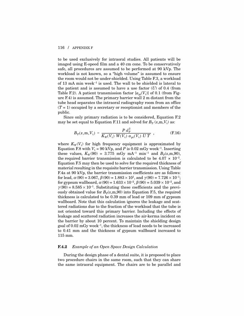
116 / APPENDIX F
to be used exclusively for intraoral studies. All patients will beimaged using E-speed film and a 40 cm cone. To be conservativelysafe, all procedures are assumed to be performed at 90 kVp. Theworkload is not known, so a “high volume” is assumed to ensurethe room would not be under-shielded. Using Table F.3, a workloadof 13 mA min week–1 is used. The wall to be shielded is lateral tothe patient and is assumed to have a use factor (U) of 0.4 (fromTable F.2). A patient transmission factor [apt(Vt)] of 0.1 (from Fig-ure F.4) is assumed. The primary barrier wall 2 m distant from thetube head separates the intraoral radiography room from an office(T = 1) occupied by a secretary or receptionist and members of thepublic.
Since only primary radiation is to be considered, Equation F.2may be set equal to Equation F.11 and solved for BP (x,m,Vt) as:
, (F.16)
where KW (Vt) for high frequency equipment is approximated byEquation F.8 with Vt = 90 kVp, and P is 0.02 mGy week–1. Insertingthese values, KW (90) = 3.775 mGy mA–1 min–1 and BP(x,m,90),the required barrier transmission is calculated to be 4.07 × 10⁻².Equation F.5 may then be used to solve for the required thickness ofmaterial resulting in the requisite barrier transmission. Using TableF.4a at 90 kVp, the barrier transmission coefficients are as follows:for lead, α (90) = 3.067, β (90) = 1.883 × 101, and γ (90) = 7.726 × 10⁻¹;for gypsum wallboard, α (90) = 1.633 × 10⁻², β (90) = 5.039 × 10⁻², andγ (90) = 8.585 × 10⁻¹. Substituting these coefficients and the previ-ously obtained value for BP(x,m,90) into Equation F.5, the requiredthickness is calculated to be 0.39 mm of lead or 109 mm of gypsumwallboard. Note that this calculation ignores the leakage and scat-tered radiations due to the fraction of the workload that the tube isnot oriented toward this primary barrier. Including the effects ofleakage and scattered radiation increases the air-kerma incident onthe barrier by about 10 percent. To maintain the shielding designgoal of 0.02 mGy week–1, the thickness of lead needs to be increasedto 0.41 mm and the thickness of gypsum wallboard increased to115 mm.
F.4.2 Example of an Open Space Design Calculation
During the design phase of a dental suite, it is proposed to placetwo procedure chairs in the same room, such that they can sharethe same intraoral equipment. The chairs are to be parallel and
BP x,m,Vt( ) P dP2
KW Vt( ) W Vt( ) apt Vt( ) U T --------------------------------------------------------------------------=

F.4 EXAMPLES OF BARRIER CALCULATIONS / 117
2 m apart, separated by an opaque, but otherwise radiolucent bar-rier. The high frequency equipment operates at 70 or 100 kVp and10 mA. To provide a conservatively safe calculation, it is assumedthat all procedures are performed at 100 kVp and a “heavy” work-load of 12 mA min week–1. The primary, scattered and leakage airkermas are calculated with Equations F.2, F.11, F.12 and F.15under the following assumptions: the barrier thickness is zero, theuse factor is 0.4 (since the chairs are parallel), the occupancy factoris one, the patient transmission factor is 0.1, and the tube is alwaysoperated at its maximum leakage technique factors of 100 kVp andaverage leakage current in 1 h of 0.5 mA. Under these conditionsthe air kermas due to primary, scattered and leakage radiations are0.563, 0.012 and 0.053 mGy week–1, for a total of 0.63 mGy week–1.However, the same patient will not be present for all procedures inan entire week. A more reasonable assumption is that a givenpatient might be present for 1/20 to 1/10 of the workload, for a totalair-kerma range of 0.03 to 0.06 mGy week–1, which exceeds theshielding design goal of 0.02 mGy week–1 for uncontrolled areas.To reduce the air-kerma level from one procedure area to the otherto the shielding design goal, the radiolucent barrier needs to bemodified so that it contains at least 0.08 mm of lead, 2.6 cm of gyp-sum wallboard, or 1.1 cm of plate glass.
This design would also exceed the shielding design goal for acontrolled area (0.1 mGy week–1) for a worker who might be presentin the room a significant portion of the time (and positioned inthe path of the primary beam), since the total air kerma is0.63 mGy week–1. Any physical layout that permits simultaneousaccommodation of two patients in one room may also permit unnec-essary or excessive occupational exposure. For example, a memberof the occupationally-exposed staff may expose a radiograph for onepatient while a second member of the staff is attending the secondpatient in the room. It is usual radiology practice that no one butthe patient should be in the room at the time of exposure of staticimage receptors such as for dental radiographs. An appropriatebarrier between the two chairs is the most effective remedy for boththe second patient and the dental worker.
Alternatively, since many intraoral imaging views are lateral oroblique, simply orienting the chairs back to back will greatly reducethe amount of primary radiation that one chair receives from theother. If a use factor of 0.2 is assumed for the anterioposterior orposteroanterior orientation, the primary air kerma would be cut inhalf, and a new evaluation could be made to see if the P values forcontrolled and uncontrolled areas are met. The use of the vertical

118 / APPENDIX F
beam technique with the patient reclined would further reduce theuse factor to near zero for periapical but not bitewing radiography(Section 3.1.4.1.3).
F.5 Examples of Approximate Barrier Thickness Calculations
In some situations accurate calculations may not be possible(due for instance to unavailability of all necessary information) ora conservatively safe (thicker) barrier calculation may be desired.In this case, the simplified techniques discussed below may beused. The basis for this method is to make simplifying assumptionsand to convert the results of application of the exact technique totable form.
Tables F.5 to F.10 are the results of exact calculations ofrequired barrier thickness for primary and secondary (leakage plusscattered) radiation. The following assumptions have been made ingenerating Tables F.5 to F.10. For leakage radiation, the instanta-neous tube current is assumed to be 10 mA regardless of kVp andthe duty cycle is assumed to be 1/20, resulting in an effective leak-age current of 0.5 mA. Housing leakage is assumed to just meet theleakage radiation standard at the kVp given in the lookup column.(This assumption will always result in an overestimate of leakageradiation for housings designed to meet the standard at a higherkVp than they are typically operated.) The scattered radiation areais assumed to be 46 cm2 and the distance to the scattered radiationvolume is assumed to be 40 cm (long cone). The scattering angle isassumed to be 90 degrees. The workload is assumed to be incurredat the same kVp.
F.5.1 Shielding Tables for Various Barrier Materials
Tables F.5 to F.10, list the thickness required for primary andsecondary protective barriers of lead, gypsum wallboard, and solidconcrete that were calculated on the basis of the assumptions givenabove. Table F.11 lists the properties of several common buildingmaterials. Studies have been made of several commonly used wallsections to determine their transmission properties for primaryand secondary dental x rays (MacDonald et al., 1983). Systematicstudies of the properties of a wide range of materials used forshielding diagnostic x rays have been reported (Archer et al., 1994;Simpkin, 1995). The results of these studies are summarized in

F.5 EXAMPLES OF APPROXIMATE THICKNESS CALCULATIONS / 119
Tables F.4a and F.4b. Shielding properties depend upon the wave-form of the incident x rays, with greater thickness required forconstant-potential equipment. Note that, compared to earlier (nowobsolete) reports such as NCRP Reports No. 35 and No. 49 (NCRP,1970; 1976), the data given in this Report are more representativeof the beam quality (particularly added filtration standards) now inuse.
F.5.2 Use of Simplified Barrier Thickness Tables
Shielding requirements of a dental office can be derived from adetermination of the following parameters:
1. the maximum kVp at which the machine is operated2. the distance from the source of radiation (x-ray tube) to
position of interest3. the weekly workload (milliampere-minutes per week)4. the occupancy factor (Table F.1)5. the leakage radiation characteristics of the unit
The following examples illustrate the use of barrier thicknesstables.
F.5.2.1 Example I. A member of the public frequently spends halfof his workday in a room directly below a dental x-ray room. Whenstanding, the upper part of his body can come within 2 m of thex-ray source. The x-ray machine uses a constant-potential wave-form, is operated only at 70 kVp, and is designed to meet the0.25 mGy h–1 leakage radiation standard. The maximum weeklyworkload is estimated to be 32 mA min. The minimum floor thick-ness is 5 cm of concrete [density 2.4 g cm–3 (147 lb ft–3)]. Is theshielding adequate?
Conditions:Type of barrier: SecondaryOccupancy factor: 1/2Shielding design goal: Uncontrolled area,
P = 0.02 mGy week–1
Minimum distance from source: 2 mOperating potential: 70 kVp (constant potential)Workload: 32 mA min week–1
Barrier material and thickness Concrete, 5.1 cm (2 in)

TABLE F.5—Primary barrier thickness for single-phase units.a
aptWUT(mA min week–1)
Distance (m)
8421
0.5 0.25
0.125
1.00 1.411.00
2.001.411.00
2.832.001.411.00
4.002.832.001.411.00
5.664.002.832.001.411.00
8.005.664.002.832.001.411.00
kVp 50 70 90 50 70 90 50 70 90 50 70 90 50 70 90 50 70 90 50 70 90
Controlled areas (P = 0.1)
Lead(mm)
0.16 0.40 1.10 0.12 0.31 0.87 0.09 0.23 0.67 0.06 0.16 0.49 0.04 0.10 0.35 0.02 0.06 0.23 0.00 0.03 0.14
Concrete(cm)
2.05 4.19 8.58 1.62 3.33 7.14 1.23 2.56 5.79 0.86 1.88 4.53 0.53 1.28 3.39 0.23 0.78 2.37 0.00 0.36 1.49
Gypsumwallboard(cm)
5.21 12.57 25.87 3.95 9.89 21.40 2.84 7.42 17.09 1.88 5.23 13.01 1.08 3.38 9.31 0.43 1.91 6.10 0.00 0.80 3.50
Steel (mm)
0.96 2.63 8.01 0.72 1.99 6.32 0.52 1.44 4.74 0.35 0.98 3.35 0.20 0.62 2.19 0.08 0.34 1.30 0.00 0.14 0.68
Plate glass (cm)
2.27 4.98 9.63 1.74 3.96 8.00 1.26 3.02 6.45 0.85 2.17 4.98 0.50 1.44 3.64 0.20 0.84 2.45 0.00 0.37 1.46

121
Uncontrolled areas (P = 0.02)
Lead (mm)
0.26 0.67 1.71 0.21 0.55 1.43 0.17 0.44 1.17 0.13 0.34 0.94 0.10 0.25 0.73 0.07 0.18 0.55 0.04 0.12 0.39
Concrete (cm)
3.15 6.48 12.18 2.65 5.45 10.59 2.19 4.48 9.06 1.75 3.60 7.60 1.35 2.80 6.21 0.98 2.09 4.92 0.63 1.47 3.75
Gypsumwallboard(cm)
8.55 19.26 36.54 7.05 16.32 31.91 5.64 13.46 27.33 4.34 10.73 22.83 3.18 8.19 18.46 2.18 5.90 14.29 1.32 3.94 10.45
Steel (mm)
1.61 4.37 12.20 1.31 3.59 10.37 1.04 2.86 8.58 0.79 2.19 6.85 0.58 1.61 5.23 0.40 1.12 3.77 0.24 0.72 2.53
Plate glass (cm)
3.68 7.55 13.53 3.05 6.42 11.83 2.45 5.32 10.16 1.90 4.28 8.52 1.41 3.31 6.94 0.98 2.43 5.44 0.60 1.66 4.05
aThe shielding design goal (P) is given in units of milligray (air kerma) per week. Since single-phase concrete attenuation data were notavailable, constant-potential attenuation parameters were used for the generation of the concrete section of this table.

TABLE F.6—Primary barrier thickness for constant-potential units.a
aptWUT (mA min week–1)
Distance (m)
8421
0.5 0.25
0.125
1.00 1.411.00
2.001.411.00
2.832.001.411.00
4.002.832.001.411.00
5.664.002.832.001.411.00
8.005.664.002.832.001.411.00
kVp 50 70 90 50 70 90 50 70 90 50 70 90 50 70 90 50 70 90 50 70 90
Controlled areas (P = 0.1)
Lead (mm)
0.20 0.49 1.37 0.16 0.39 1.12 0.12 0.29 0.88 0.09 0.21 0.66 0.06 0.14 0.46 0.03 0.09 0.30 0.01 0.04 0.18
Concrete (cm)
2.32 4.57 9.17 1.87 3.68 7.70 1.46 2.87 6.31 1.08 2.15 5.01 0.73 1.52 3.82 0.41 0.98 2.76 0.11 0.53 1.82
Gypsum wallboard (cm)
6.57 14.41 30.31 5.18 11.66 25.67 3.90 9.05 21.11 2.75 6.65 16.68 1.76 4.54 12.48 0.93 2.77 8.64 0.25 1.38 5.33
Steel (mm)
1.18 3.17 9.65 0.92 2.48 7.81 0.70 1.86 6.07 0.50 1.34 4.49 0.32 0.90 3.13 0.17 0.55 2.02 0.05 0.28 1.17
Plate glass (cm)
2.78 5.71 11.10 2.21 4.66 9.50 1.68 3.66 7.91 1.20 2.74 6.34 0.78 1.92 4.83 0.41 1.22 3.41 0.11 0.63 2.15

123
Uncontrolled areas (P = 0.02)
Lead (mm)
0.31 0.75 1.99 0.26 0.64 1.72 0.21 0.52 1.45 0.17 0.42 1.20 0.13 0.32 0.95 0.10 0.24 0.72 0.06 0.16 0.52
Concrete (cm)
3.46 6.94 12.81 2.95 5.88 11.21 2.47 4.88 9.66 2.01 3.96 8.16 1.59 3.12 6.74 1.20 2.37 5.42 0.84 1.72 4.19
Gypsum wallboard (cm)
10.16 21.12 41.21 8.57 18.19 36.50 7.05 15.32 31.81 5.61 12.53 27.16 4.29 9.87 22.57 3.11 7.40 18.09 2.06 5.19 13.80
Steel (mm)
1.85 5.01 14.17 1.54 4.18 12.20 1.26 3.41 10.26 1.00 2.69 8.39 0.77 2.05 6.61 0.56 1.50 4.98 0.37 1.03 3.54
Plate glass (cm)
4.23 8.31 14.85 3.59 7.17 13.23 2.97 6.06 11.62 2.39 4.99 10.01 1.85 3.97 8.42 1.35 3.03 6.84 0.91 2.17 5.31
aThe shielding design goal (P) is given in units of milligray (air kerma) per week.

TABLE F.7—Secondary barrier thickness for single-phase units with 0.876 mGy h–1 (0.1 R h–1) leakage.a
W(1 – U)T (mA min week–1)
Distance (m)
128 64 32 16 8 4 2
1.00 1.411.00
2.001.411.00
2.832.001.411.00
4.002.832.001.411.00
5.664.002.832.001.411.00
8.005.664.002.832.001.411.00
kVp 50 70 100 50 70 100 50 70 100 50 70 100 50 70 100 50 70 100 50 70 100
Controlled areas (P = 0.1)
Lead (mm)
0.60 0.85 1.78 0.48 0.69 1.44 0.37 0.53 1.10 0.25 0.36 0.76 0.14 0.20 0.42 0.03 0.04 0.10 0.00 0.00 0.00
Concrete (cm)
4.00 7.10 9.24 3.23 5.74 7.48 2.47 4.38 5.73 1.70 3.02 3.98 0.94 1.67 2.26 0.18 0.36 0.63 0.00 0.00 0.00
Gypsum wallboard (cm)
9.37 16.12 24.61 7.57 13.04 19.93 5.78 9.95 15.26 3.98 6.88 10.60 2.19 3.81 5.98 0.43 0.82 1.59 0.00 0.00 0.00
Steel (mm)
2.20 4.67 9.80 1.78 3.77 7.93 1.36 2.88 6.06 0.94 1.99 4.18 0.51 1.09 2.32 0.10 0.23 0.54 0.00 0.00 0.00
Plate glass (cm)
4.14 6.34 9.13 3.35 5.12 7.40 2.55 3.91 5.66 1.76 2.70 3.94 0.97 1.50 2.23 0.19 0.33 0.61 0.00 0.00 0.00

125
Uncontrolled areas (P = 0.02)
Lead (mm)
0.86 1.22 2.56 0.74 1.06 2.21 0.63 0.90 1.87 0.51 0.73 1.53 0.40 0.57 1.19 0.28 0.41 0.85 0.17 0.24 0.51
Concrete (cm)
5.74 10.19 13.24 4.97 8.83 11.47 4.20 7.47 9.71 3.44 6.11 7.95 2.67 4.74 6.19 1.90 3.38 4.44 1.14 2.03 2.71
Gypsum wallboard (cm)
13.44 23.12 35.23 11.65 20.03 30.55 9.85 16.94 25.86 8.05 13.86 21.18 6.26 10.77 16.50 4.46 7.69 11.83 2.67 4.62 7.20
Steel (mm)
3.16 6.70 14.05 2.74 5.80 12.18 2.31 4.91 10.30 1.89 4.01 8.43 1.47 3.12 6.55 1.05 2.22 4.68 0.63 1.33 2.82
Plate glass (cm)
5.94 9.08 13.07 5.15 7.87 11.33 4.36 6.66 9.59 3.56 5.45 7.86 2.77 4.23 6.13 1.97 3.03 4.40 1.18 1.82 2.68
aThe shielding design goal (P) is given in units of milligray (air kerma) per week. The leakage technique factors assumed 0.5 mA aver-age leakage current with sufficient housing shielding to just meet the leakage standard at the kVp indicated in the column. The scatteredradiation area is assumed to be 46 cm2 and the distance to the scattered radiation volume is assumed to be 40 cm (long cone).

TABLE F.8—Secondary barrier thickness for constant-potential units with 0.876 mGy h–1 (0.1 R h–1) leakage.a
W(1 – U)T(mA min week–1)
Distance (m)
128 64 32 16 8 4 2
1.00 1.411.00
2.001.411.00
2.832.001.411.00
4.002.832.001.411.00
5.664.002.832.001.411.00
8.005.664.002.832.001.411.00
kVp 50 70 100 50 70 100 50 70 100 50 70 100 50 70 100 50 70 90 50 70 100
Controlled areas (P = 0.1)
Lead (mm)
0.41 0.68 1.46 0.33 0.55 1.18 0.26 0.42 0.90 0.18 0.29 0.63 0.10 0.16 0.35 0.02 0.04 0.10 0.00 0.00 0.00
Concrete (cm)
4.01 7.12 9.28 3.24 5.76 7.52 2.48 4.40 5.77 1.71 3.05 4.03 0.95 1.70 2.32 0.20 0.40 0.71 0.00 0.00 0.00
Gypsum wallboard (cm)
9.34 15.79 25.03 7.55 12.78 20.31 5.77 9.77 15.60 3.99 6.78 10.91 2.22 3.80 6.28 0.47 0.91 1.88 0.00 0.00 0.00
Steel (mm)
1.99 5.07 10.65 1.61 4.10 8.62 1.23 3.13 6.59 0.85 2.17 4.57 0.47 1.20 2.57 0.10 0.27 0.68 0.00 0.00 0.00
Plate glass (cm)
3.73 6.28 8.62 3.02 5.08 7.00 2.31 3.89 5.39 1.60 2.70 3.78 0.89 1.51 2.19 0.19 0.37 0.67 0.00 0.00 0.00

127
Uncontrolled areas (P = 0.02)
Lead (mm)
0.59 0.98 2.10 0.52 0.85 1.82 0.44 0.72 1.54 0.36 0.59 1.27 0.28 0.46 0.99 0.20 0.33 0.71 0.12 0.20 0.44
Concrete (cm)
5.79 10.28 13.36 5.02 8.92 11.59 4.25 7.55 9.83 3.49 6.19 8.07 2.72 4.83 6.32 1.95 3.47 4.57 1.19 2.12 2.85
Gypsum wallboard (cm)
13.47 22.76 35.97 11.68 19.75 31.25 9.90 16.74 26.52 8.12 13.73 21.80 6.33 10.73 17.09 4.55 7.72 12.39 2.78 4.73 7.74
Steel (mm)
2.88 7.31 15.35 2.50 6.35 13.32 2.12 5.38 11.29 1.73 4.41 9.26 1.35 3.44 7.23 0.97 2.47 5.21 0.59 1.51 3.20
Plate glass (cm)
5.38 9.05 12.37 4.67 7.85 10.75 3.96 6.65 9.13 3.24 5.46 7.51 2.53 4.26 5.90 1.82 3.07 4.29 1.11 1.89 2.69
aThe shielding design goal (P) is given in units of milligray (air kerma) per week. The leakage technique factors assumed 0.5 mA aver-age leakage current with sufficient housing shielding to just meet the leakage standard at the kVp indicated in the column. The scatteredradiation area is assumed to be 46 cm2 and the distance to the scattered radiation volume is assumed to be 40 cm (long cone).

TABLE F.9—Secondary barrier thickness for single-phase units with 0.25 mGy h–1 leakage.a
W(1 – U)T (mA min week–1)
Distance (m)
128 64 32 16 8 4 2
1.00 1.411.00
2.001.411.00
2.832.001.411.00
4.002.832.001.411.00
5.664.002.832.001.411.00
8.005.664.002.832.001.411.00
kVp 50 70 100 50 70 100 50 70 100 50 70 100 50 70 100 50 70 100 50 70 100
Controlled areas (P = 0.1)
Lead (mm)
0.39 0.56 1.17 0.28 0.40 0.83 0.16 0.23 0.50 0.05 0.08 0.20 0.00 0.00 0.01 0.00 0.00 0.00 0.00 0.00 0.00
Concrete (cm)
2.62 4.66 6.19 1.86 3.31 4.48 1.10 1.98 2.82 0.37 0.72 1.30 0.00 0.00 0.07 0.00 0.00 0.00 0.00 0.00 0.00
Gypsum wallboard (cm)
6.14 10.65 16.62 4.36 7.59 12.01 2.58 4.56 7.49 0.84 1.66 3.28 0.00 0.00 0.15 0.00 0.00 0.00 0.00 0.00 0.00
Steel (mm)
1.44 3.06 6.49 1.02 2.17 4.63 0.60 1.29 2.80 0.19 0.44 1.07 0.00 0.00 0.03 0.00 0.00 0.00 0.00 0.00 0.00
Plate glass (cm)
2.72 4.19 6.18 1.93 2.99 4.48 1.14 1.80 2.82 0.38 0.67 1.27 0.00 0.00 0.07 0.00 0.00 0.00 0.00 0.00 0.00

129
Uncontrolled areas (P = 0.02)
lead (mm)
0.65 0.93 1.94 0.54 0.77 1.60 0.42 0.60 1.26 0.31 0.44 0.92 0.19 0.28 0.59 0.08 0.12 0.27 0.00 0.00 0.04
Concrete (cm)
4.35 7.74 10.14 3.59 6.38 8.39 2.82 5.02 6.65 2.06 3.67 4.93 1.30 2.33 3.25 0.56 1.04 1.68 0.00 0.00 0.36
Gypsum wallboard (cm)
10.21 17.63 27.19 8.41 14.54 22.51 6.62 11.47 17.86 4.83 8.40 13.23 3.05 5.36 8.68 1.29 2.40 4.34 0.00 0.00 0.80
Steel (mm)
2.40 5.09 10.73 1.97 4.19 8.86 1.55 3.30 6.99 1.13 2.41 5.13 0.71 1.52 3.28 0.30 0.66 1.50 0.00 0.00 0.19
Plate glass (cm)
4.51 6.93 10.09 3.72 5.72 8.36 2.93 4.51 6.63 2.14 3.30 4.93 1.35 2.11 3.25 0.57 0.96 1.66 0.00 0.00 0.33
aThe shielding design goal (P) given in units of milligray (air kerma) per week. The leakage technique factors assumed 0.5 mA averageleakage current with sufficient housing shielding to just meet the leakage standard at the kVp indicated in the column. The scatteredradiation area is assumed to be 46 cm2 and the distance to the scattered radiation volume is assumed to be 40 cm (long cone).

TABLE F.10—Secondary barrier thickness for constant-potential units with 0.25 mGy h–1 leakage.a
W(1 – U)T (mA min week–1)
Distance (m)
128 64 32 16 8 4 2
1.00 1.411.00
2.001.411.00
2.832.001.411.00
4.002.832.001.411.00
5.664.002.832.001.411.00
8.005.664.002.832.001.411.00
kVp 50 70 100 50 70 100 50 70 100 50 70 100 50 70 100 50 70 90 50 70 100
Controlled areas (P = 0.1)
Lead (mm)
0.27 0.45 0.98 0.19 0.32 0.70 0.11 0.19 0.43 0.04 0.07 0.19 0.00 0.00 0.02 0.00 0.00 0.00 0.00 0.00 0.00
Concrete (cm)
2.63 4.69 6.27 1.87 3.34 4.57 1.12 2.02 2.93 0.40 0.78 1.43 0.00 0.00 0.23 0.00 0.00 0.00 0.00 0.00 0.00
Gypsum wallboard (cm)
6.15 10.52 17.32 4.38 7.54 12.69 2.63 4.61 8.15 0.93 1.83 3.92 0.00 0.00 0.57 0.00 0.00 0.00 0.00 0.00 0.00
Steel (mm)
1.31 3.34 7.11 0.93 2.37 5.10 0.56 1.42 3.14 0.20 0.53 1.33 0.00 0.00 0.14 0.00 0.00 0.00 0.00 0.00 0.00
Plate glass (cm)
2.46 4.18 6.05 1.76 3.01 4.46 1.06 1.85 2.90 0.38 0.75 1.43 0.00 0.00 0.22 0.00 0.00 0.00 0.00 0.00 0.00

131
Uncontrolled areas (P = 0.02)
Lead (mm)
0.45 0.74 1.61 0.37 0.62 1.34 0.30 0.49 1.06 0.22 0.36 0.79 0.14 0.23 0.52 0.06 0.11 0.26 0.00 0.01 0.06
Concrete (cm)
4.40 7.83 10.29 3.64 6.47 8.55 2.88 5.12 6.81 2.11 3.77 5.10 1.36 2.43 3.44 0.63 1.16 1.88 0.00 0.11 0.57
Gypsum wallboard (cm)
10.28 17.47 28.20 8.49 14.46 23.49 6.72 11.46 18.80 4.94 8.48 14.14 3.18 5.53 9.57 1.46 2.67 5.20 0.00 0.24 1.47
Steel (mm)
2.19 5.58 11.79 1.81 4.61 9.76 1.43 3.64 7.74 1.05 2.68 5.73 0.67 1.72 3.75 0.31 0.80 1.87 0.00 0.06 0.41
Plate glass (cm)
4.11 6.94 9.79 3.40 5.75 8.17 2.69 4.56 6.56 1.98 3.38 4.96 1.28 2.21 3.39 0.59 1.08 1.88 0.00 0.11 0.56
aThe shielding design goal (P) given in units of milligray (air kerma) per week. The leakage technique factors assumed 0.5 mA averageleakage current with sufficient housing shielding to just meet the leakage standard at the kVp indicated in the column. The scatteredradiation area is assumed to be 46 cm2 and the distance to the scattered radiation volume is assumed to be 40 cm (long cone).
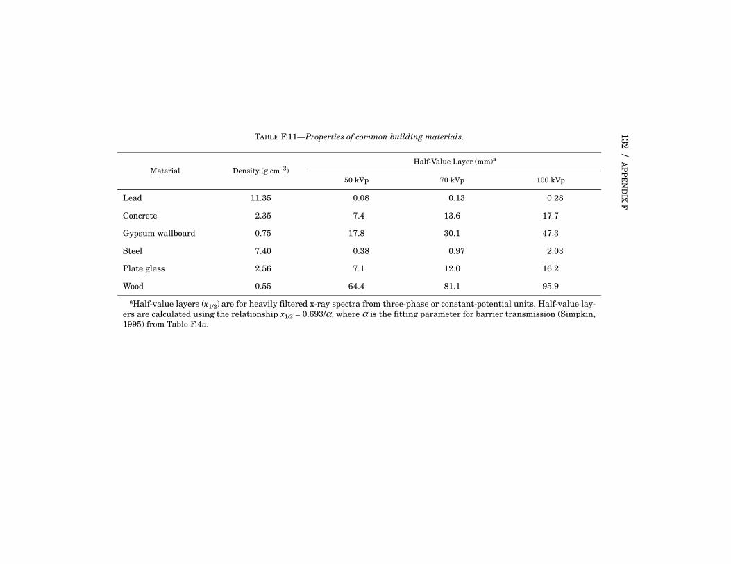
132 / AP
PE
ND
IX F
TABLE F.11—Properties of common building materials.
Material Density (g cm–3)Half-Value Layer (mm)a
50 kVp 70 kVp 100 kVp
Lead 11.35 0.08 0.13 0.28
Concrete 2.35 7.4 13.6 17.7
Gypsum wallboard 0.75 17.8 30.1 47.3
Steel 7.40 0.38 0.97 2.03
Plate glass 2.56 7.1 12.0 16.2
Wood 0.55 64.4 81.1 95.9
aHalf-value layers (x1/2) are for heavily filtered x-ray spectra from three-phase or constant-potential units. Half-value lay-ers are calculated using the relationship x1/2 = 0.693/α, where α is the fitting parameter for barrier transmission (Simpkin,1995) from Table F.4a.

F.5 EXAMPLES OF APPROXIMATE THICKNESS CALCULATIONS / 133
The solution may be found by referring to Table F.10 for second-ary protective barriers. Since the tube is never directed at the floor(U = 0), all of the workload contributes to secondary radiation, andthe product W(1 – U)T is calculated to be 16 mA min week–1. Locatethis value in the left-most column. Read across to the right to thecolumn indicating 2 m (in this case the second to the last column),then read down to the section labeled “Uncontrolled areas(P = 0.02).” Under the 70 kVp label within this distance column isthe minimum barrier thickness of 1.16 cm of concrete. Since theexisting barrier, 5.1 cm, exceeds 1.16, the existing barrier providesadequate protection for the conditions of occupancy in the roombelow the dental office. If the workload or other parameters changesignificantly, a new computation should be made.
F.5.2.2 Example II. Beyond one wall of this same dental officethere is a corridor used by the general public. The wall is made oftwo slabs of 1.4 cm (5/8 inch) type “X” gypsum wallboard. The min-imum distance to the x-ray source is 1 m. Does the wall provideadequate protection for persons using the corridor?
Conditions:Type of barrier: PrimaryOccupancy factor: 1/5 (Table F.1)Shielding design goal: Uncontrolled area,
P = 0.02 mGy week–1
Minimum distance from source: 1 mOperating potential: 70 kVp (constant potential)Workload: 15 mA min week–1
Barrier material and thickness Gypsum wallboard, 2.8 cm
The minimum barrier thickness may be found by referring toTable F.6 for the primary protective barriers of constant-potentialwaveforms. In the absence of detailed use and patient transmissiondata, it is appropriate to assume that apt = 0.1 and U = 0.4. Thusthe product aptWUT is calculated to be 0.120 mA min week–1. Avalue of 0.125 mA min week–1 may be used for table look up. Locatethis value in the left-most column. Read across to the right to thecolumn indicating 1 m (the last column), then read down to the sec-tion labeled “Uncontrolled areas (P = 0.02)”. Under the 70 kVp labelwithin the distance column is the minimum barrier thickness of5.19 cm of gypsum wallboard. Secondary radiation also impingeson this barrier. Using Table F.10 with a W(1 – U)T value of1.8 mA min week–1 at 1 m and the same shielding design goal, the

134 / APPENDIX F
gypsum wallboard thickness for 2 mA min week–1 is 0.24 cm. There-fore, the 2.8 cm gypsum wallboard is enough for the secondary radi-ation, but not for the primary radiation. One way to provideadequate shielding for the primary radiation is to double the thick-ness of the gypsum wallboard.
F.5.2.3 Example III. In the design phase of a new intraoral imag-ing suite the barrier thickness of a wall between the imaging equip-ment and a waiting room is to be specified. The equipment is singlephase, designed to meet the 0.25 mGy h–1 leakage standard andprovides a maximum potential of 70 kVp. A workload of32 mA min week–1 is assumed. The orientation of the equipmentresults in the wall being a primary barrier with a use factor of 0.4.Figure F.4 is used to estimate the patient transmission factor of0.07. The waiting room lies directly on the other side of the wall,1 m distant from the equipment.
Conditions:Type of barrier: PrimaryOccupancy factor: 1 (Table F.1)Shielding design goal: Uncontrolled area,
P = 0.02 mGy week–1
Minimum distance from source: 1 mOperating potential: 70 kVp (single phase)Workload: 32 mA min week–1
The minimum barrier thickness may be found by referring toTable F.5 for primary protective barriers of single-phaseequipment. Since the product aptWUT is calculated to be0.9 mA min week–1, a value of 1 mA min week–1 may be usedfor table lookup. Locate this value in the left-most column. Readacross to the right to the column indicating 1 m (the fourth columnfrom the left), then read down to the section labeled “Uncontrolledarea (P = 0.02)”. Under the 70 kVp label within the distance columnis the minimum barrier thickness of 0.34 mm of lead or 10.73 cmof gypsum wallboard. Since the barrier thickness of gypsum wall-board would require eight slabs of type “X” gypsum wallboard(1.4 cm each), lead is the practical barrier material.
Secondary radiation also impinges upon this barrier. Table F.9is used with a W(1 – U)T value of 19 mA min week–1 at 1 m and thesame shielding design goal (P = 0.02). However, at 1 m, Table F.9has entries only for 16 and 32 mA min week–1, with resultingshielding thicknesses of 0.44 and 0.60 mm of lead. Although not

F.6 SUMMARY / 135
mathematically identical to the exact solution, a linear interpola-tion can be made between these two values to yield an approximatethickness of 0.47 mm of lead. The recommended thickness forsecondary radiation should thus be somewhat greater than about0.5 mm of lead. In fact, it is often difficult to obtain leaded wall-board with less than 0.79 mm (1/32 inch or 2 pounds per squarefoot) lead thickness. Hence the minimum practical lead thicknessfor this wall could be 0.79 mm, resulting in greater shielding thanis required for either primary or secondary radiation.
F.6 Summary
As demonstrated in this Appendix, various techniques are avail-able for calculations of required barrier thickness for dental instal-lations. While varying degrees of sophistication may be used, theacceptability of upgraded existing or planned new barriers cannotbe assumed. Particularly for new construction and typical circum-stances, appropriate shielding adds little to the cost of construc-tion. Also, there needs to be a performance assessment by aqualified expert to confirm that occupational and public effectivedose limits will not be exceeded by the structural shielding design,prior to facility operation. The recommendations in this Report areapplied to upgraded or new shielding designs, but not to existingbarriers that otherwise met prior requirements.

136
Appendix G
Radiation Quantities and Units
NCRP presently expresses the values of radiation quantities inthe International System of Units (le Systeme Internationaled’Unites, or SI units). These units have replaced the previouslyused units (Table G.1) in most of the scientific literature. The quan-tity exposure, previously expressed in roentgens (R), has beenlargely replaced by the quantity air kerma (K) (an acronym forkinetic energy released per unit mass), which is expressed in thesame units as absorbed dose. However, some older instrumentsmay provide readout only in roentgens; with others either SI orthe previous units may be selected. Absorbed dose, the energyimparted by ionizing radiation to matter per unit mass, isexpressed in gray (Gy) (the previous name was the rad). Equivalentdose, expressed in sievert (Sv) (the previous name was the rem), isused extensively in radiation protection. Equivalent dose is themean absorbed dose in an organ or tissue modified by the radiationweighting factors for different types of radiation (e.g., photons, neu-trons, heavy charged particles). For diagnostic x rays (includingdental), the radiation weighting factor is assigned the value of one,and absorbed dose in gray is numerically equal to equivalent dosein sievert
Another quantity, effective dose, is useful in comparing differentdose distributions in the body. It takes into account the equivalentdoses in radiosensitive organs or tissues, each modified by a tissueweighting factor that represents the relative contribution of risk ofstochastic effect to that organ or tissue to total stochastic risk. Thetissues receiving the higher doses in patients from dental radiogra-phy are portions of the active bone marrow, thyroid, bone surface ofthe skull, brain and salivary glands.
Conversion factors from the previous units to SI units are givenin Table G.1. Detailed discussions of these concepts are givenelsewhere (Bushberg et al., 2001; ICRU, 1993; 1998; Johns andCunningham, 1983; NCRP, 1985).

G. R
AD
IAT
ION
QU
AN
TIT
IES
AN
D U
NIT
S / 137
TABLE G.1—Radiation quantities and units.
Quantity SI Unitsa Previous Unitsa
ConversionUnit Special Name Unit Special Name
Exposure C kg–1 none C kg–1 roentgen (R) 1 R = 2.58 × 10⁻⁴ C kg–1
Kerma; absorbed dose J kg–1 gray (Gy)1 Gy = 1 J kg–1
erg g–1 rad1 rad = 100 erg g–1
1 Gy = 100 rad
Equivalent dose; effective dose
J kg–1 sievert (Sv)1 Sv = 1 J kg–1
erg g–1 rem1 rem = 100 erg g–1
1 Sv = 100 rem
aC = coulombJ = jouleg = gram kg = kilogram

138
Glossary
absorbed dose (D): The energy imparted by ionizing radiation to matterper unit mass of irradiated material at the point of interest. In theSysteme Internationale (SI), the unit is J kg–1, given the special namegray (Gy). 1 Gy = 1 J kg–1.
air kerma (K): (see kerma). Kerma in air. In this Report, the symbol Kalways refers to the quantity air kerma (in place of the usual symbolKa), followed by an appropriate subscript to further describe the quan-tity (e.g., KP , air kerma from primary radiation).
ampere: Unit of electric current. One ampere is produced by 1 volt actingthrough a resistance of 1 ohm.
anode: The positive terminal of an x-ray tube. Typically, a tungsten blockembedded in a copper stem and set at an angle to the cathode (the neg-ative terminal of an x-ray tube, from which electrons are emitted). Theanode emits x rays from the point of impact of the electron streamfrom the cathode.
area (or facility) dosimeter: A device used to estimate the absorbeddose or effective dose received by personnel, but not worn by anindividual.
arthrography: Radiographic evaluation of a joint after injection of radio-paque contrast material into the joint space(s).
as low as reasonably achievable (ALARA): The principle of reducingthe radiation dose of exposed persons to levels as low as is reasonablyachievable, economic and social factors being taken into account.
attenuation: Loss of energy from a beam of ionizing radiation by scatterand absorption.
background: Ionizing radiation present in the region of interest andcoming from sources other than that of primary concern (see also nat-ural background radiation).
bisecting angle technique (bisect angle geometry): A technique forthe radiographic exposure of intraoral image receptors whereby thecentral axis of the x-ray beam is directed at right angles to a planedetermined by bisecting the angle formed by (1) the long axis of thetooth or teeth being imaged, and (2) the plane in which the imagereceptor is positioned behind the teeth.
bitewing radiograph: An intraoral radiograph that demonstrates thecrowns, necks and coronal thirds of the roots of both upper and lowerteeth. So named because the patient bites upon a tab or “wing” project-ing from the center of the image-receptor packet.
cathode: (see anode).

GLOSSARY / 139
cephalometer: A device used in obtaining cephalometric images. It con-sists of a source assembly, a connector arm, a head holder, and animage-receptor holder.
cephalometric radiography: Images of the head, primarily the dento-facial structures, usually obtained in lateral and posteroanteriororientation. Reproducible geometry is maintained by use of a cepha-lometer. The images are used to measure and study maxillofacialgrowth and maxilla-mandible relationships.
collimator (or beam-limiting device): A device that provides a meansto restrict the dimensions of the useful beam.
computed tomography (CT): An imaging procedure that uses multiplex-ray transmission measurements and a computer program to gener-ate tomographic images of the patient.
cone: (see position indicating device).constant potential: The potential formed by a constant-voltage
generator.contrast:
subject contrast: the difference between two anatomic structures inattenuation of an x-ray beam or:
, (G.1)
where C is subject contrast, and IA and IB are beam intensities aftertraversing structures A and B.film contrast: the ability of a film (or other image receptor) to trans-late subject contrast to differences in the resulting image. Film con-trast depends on both film characteristics and processing.
dental assistant: A member of the dental office staff whose principalduty is chair side assistance of the dentist in delivery of care. Theassistant, properly trained, may be credentialed for exposure of dentalradiographs.
dental hygienist: A member of the dental office staff whose principalduty is performing oral prophylaxis and related procedures; in theUnited States, a graduate of an accredited educational program indental hygiene and registered in the state or political jurisdictionin which the practice is located. The dental hygiene curriculumincludes training in radiography and the hygienist is credentialed toexpose dental radiographs.
dental radiographic technologist: An individual who is trained andskilled in, and credentialed for, performing both routine and special-ized radiographic examinations of the dentofacial region.
dentist: A graduate of an accredited dental institution with a degree ofD.D.S., D.M.D. or equivalent.
deterministic effects: Effects that occur in all individuals who receivegreater than the threshold dose and for which the severity of the effectvaries with the dose.
C IA IB–
IB-----------------=

140 / GLOSSARY
detriment: The overall risk of radiation-induced health outcomes, includ-ing fatal and nonfatal cancer, genetic effects, and loss of life span fromcancer and hereditary disease, weighted for severity and time ofexpression of the harmful effect, and averaged over both sexes and allages in the population of interest (i.e., general or working population).
diagnostic source assembly: A diagnostic source housing (x-ray tubehousing) assembly with a beam-limiting device attached.
diagnostic reference level: A patient dose-related quantity per x-ray procedure or image that, if consistently exceeded in clinical prac-tice, should elicit investigation and efforts for improved patient dosemanagement.
digital radiography: A diagnostic procedure using an appropriate radi-ation source and imaging system that collects, processes, stores,recalls and presents image information in a digital array rather thanon film.
dose: (see absorbed dose). Often used generically in place of a specificquantity, such as equivalent dose.
dose limit (annual): The maximum effective dose an individual may bepermitted in any year from a given category of sources (e.g., the occu-pational dose limit).
dosimetry: The science or technique of determining radiation dose.dosimeter: Dose measuring device (see also personal dosimeter and
area dosimeter).effective dose (E): The sum of the weighted equivalent doses for
the radiosensitive tissues and organs of the body. It is given by theexpression:
, (G.2)
where HT is the equivalent dose in tissue or organ T and wT is the tis-sue weighting factor for tissue T.
effective dose equivalent (HE): An earlier formulation for effectivedose (ICRP, 1977; NCRP, 1987b). Used in this Report only when valuesare quoted from the literature for this earlier quantity.
entrance air kerma (or entrance skin exposure): Air kerma (or expo-sure) measured free-in-air at the location of the entry surface of anirradiated person or phantom in the absence of the person or phantom.
equivalent dose (HT): The mean absorbed dose in a tissue or organ mod-ified by the radiation weighting factor (wR) for the type and energy ofradiation. The equivalent dose in tissue T is given by the expression:
, (G.3)
where DT,R is the mean absorbed dose in the tissue or organ T due toradiation type R. The SI unit of equivalent dose is the J kg–1 with thespecial name sievert (Sv). 1 Sv = 1 J kg–1.
E wTHT∑=
HT wR DT,R( )∑=

GLOSSARY / 141
exposure: A measure of the ionization produced in air by x or gammaradiation. The unit of exposure is coulomb per kilogram (C kg–1) withthe special name roentgen (R). Air kerma is often used in place ofexposure. An exposure of 1 R corresponds to an air kerma of 8.76 mGy(see kerma, gray, roentgen).
field size: The geometrical projection of the x-ray beam on a plane per-pendicular to the central ray of the distal end of the limiting dia-phragm, as seen from the center of the front surface of the source.
film: A thin, transparent sheet of polyester or similar material coated onone or both sides with an emulsion sensitive to radiation and light.direct exposure film: Film that is highly sensitive to the directaction of x rays rather than in combination with an intensifyingscreen.screen film: Film whose light absorption characteristics are matchedto the light emission characteristics of intensifying screens; screenfilm is not designed for use as direct exposure film.
film speed: For intraoral films, film speed is expressed as the reciprocalof the exposure (i.e., R–1) necessary to produce a density of one abovebase plus fog.D-speed film: Direct exposure film with a speed range of 12 to 24 R–1.E-speed film: Direct exposure film with a speed range of 24 to 48 R–1.F-speed film: Direct exposure film with a speed range of 48 to 96 R–1.Faster films need less exposure (i.e., a larger value of R–1) to producethe same film density (e.g., F-speed film is faster than E-speed film).For screen films, film speed is usually expressed in combination withan intensifying screen.
filter; filtration: Material in the useful beam that usually absorbs pref-erentially the less penetrating radiation. The total filtration consistsof inherent and added filters.inherent filtration: The filter permanently in the useful beam; itincludes the window of the x-ray tube and any permanent enclosurefor the tube or source.added filtration: Filter in addition to the inherent filtration.
fluoroscopy: The process of producing a real-time image using x rays.The machine used for visualization, in which the dynamic imageappears in real time on a display screen (usually video) is a fluoro-scope. The fluoroscope can also produce a static record of an imageformed on the output phosphor of an image intensifier. Theimage intensifier is an x-ray image receptor that increases the bright-ness of a fluoroscopic image by electronic amplification and imageminification.
focal spot, effective: The apparent size of the radiation source region ina source assembly when viewed from the central axis of the usefulradiation beam.
fog: A darkening of the whole or part of a radiograph by sources otherthan the radiation of the primary beam to which the film was exposed.

142 / GLOSSARY
This can be due to chemicals in the processing solutions, light, or non-primary beam radiation.
geometric distortion: Distortion of the recorded image due to the com-bined optical effect of finite size of the focal spot and geometric separa-tion of the anatomic area of interest from the image receptor and thefocal spot.
genetic effects: Changes in reproductive cells that may result in detri-ment to offspring.
gray (Gy): The special name given to the SI unit of absorbed dose andkerma. 1 Gy = 1 J kg–1.
grid: A device used to reduce scattered radiation reaching an imagereceptor during the making of a radiograph. It consists of a series ofnarrow (usually lead) strips closely spaced on their edges, separatedby spacers of low density material.
half-value layer: Thickness of a specified substance that, when intro-duced into the path of a given beam of radiation, reduces theair-kerma rate (or exposure rate) by one-half.
hazardous chemical: Any chemical that is a physical hazard or a healthhazard as defined by the Occupational Safety and Health Administra-tion (OSHA, 1994a).
image receptor: A system for deriving a diagnostically usable imagefrom the x rays transmitted through the patient. Examples:screen-film system, photostimulable storage phosphor, solid statedetector.
inherent filtration: (see filter).intraoral radiograph: Radiograph produced on an image receptor
placed intraorally and lingually or palatally to the teeth.in utero: In the uterus; refers to a fetus or embryo.inverse square law: A physical law stating that in the absence of inter-
vening absorbers, the intensity of radiation from a point source isinversely proportional to the square of the distance from the source.Example: A point source that produces 10 Gy h–1 at 1 m will produce2.5 Gy h–1 at 2 m.
ionization chamber: A device for detection of ionizing radiation or formeasurement of radiation exposure and exposure rate.
ionizing radiation: Any electromagnetic or particulate radiation capa-ble of producing ions, directly or indirectly, by interaction with matter.Examples are x-ray photons, charged atomic particles and other ions,and neutrons.
kerma (K) (kinetic energy released per unit mass): The sum of theinitial kinetic energies of all the charged particles liberated byuncharged particles per unit mass of a specified material. The SI unitfor kerma is J kg–1 with the special name gray (Gy). 1 Gy = 1 J kg–1.Kerma can be quoted for any specified material at a point in free spaceor in an absorbing medium (see also air kerma).
kilovolt (kV): A unit of electrical potential difference equal to 1,000 volts.

GLOSSARY / 143
kilovolt peak (kVp): (also see operating potential). The crest value inkilovolts of the potential difference of a pulsating potential generator.When only one-half of the wave is used, the value refers to the usefulhalf of the cycle. In this Report, the potential formed by a con-stant-potential generator is also expressed as kVp. In equations, inthis Report, the symbol Vt is used, meaning the operating potentialapplied to the x-ray tube (i.e., the kVp).
latent image: The invisible change produced in an x-ray or photographicfilm emulsion by the action of x radiation or light, from which the visi-ble image is subsequently developed and fixed chemically; or thechange produced in a photostimulable storage phosphor and recoveredby scanning with a laser.
latitude: The range between the minimum and maximum radiationexposures to an image receptor that yield diagnostic images ofstructures.
leaded apron: An apron made with lead, a radiation absorbing materialused to reduce radiation exposure.
leaded glove: A glove made with lead, a radiation absorbing materialused to reduce radiation exposure.
lead equivalent: The thickness of lead affording the same attenuation,under specified conditions, as the material in question.
leakage radiation: (see radiation).leakage technique factors: Technique factors specified for source
assemblies at which leakage radiation is measured. linear-energy transfer (LET): The linear rate of loss of energy by an
ionizing photon or charged particle traversing a medium, usuallyreported in units of keV µm–1. low-LET: Particulate or electromagnetic radiation resulting in LETbelow approximately 10 keV µm–1; electrons and x or gamma rays arecommon examples.high-LET: Particulate radiation resulting in LET greater than about10 to 100 keV µm–1; neutrons and alpha particles are commonexamples.
magnification (in medical x-ray imaging): An imaging procedure car-ried out with magnification usually produced by purposeful introduc-tion of distance between the subject and the image receptor.
material safety data sheet: Written or printed material concerning ahazardous chemical that is prepared in accordance with an Occupa-tional Safety and Health Administration regulation (OSHA, 1994a).
milliampere (mA): Electrically, 1 × 10⁻³ ampere. In radiography, the cur-rent flow from the cathode to the anode that, in turn, regulates theintensity of radiation emitted by the x-ray tube, thus directly influenc-ing radiographic density.
milliampere-minutes (mA min): The product of the x-ray tube operat-ing current and exposure time, in minutes.
milliampere-seconds (mAs): The product of the x-ray tube operatingcurrent and exposure time, in seconds.

144 / GLOSSARY
minimum detectable level: The threshold of detection for the device inquestion.
monitor: To determine the level of ionizing radiation or radioactive con-tamination in a given region. Also, a device used for this purpose.
multiple tube installation: An installation consisting of more than onex-ray source in the same room or of sources located in adjacent roomsthat are close enough to require consideration of their combined work-loads in radiation protection design.
natural background radiation: Radiation originating in naturalsources: e.g., cosmic rays, naturally occurring radioactive minerals,naturally occurring radioactive 14C and 40K in the body.
noise: The presence of random fluctuations in image intensity that do notrelate to the subject being imaged. Noise is related to both speed andresolution. Generally, faster systems have greater noise.
occlusal radiograph: An intraoral radiograph made with the imagereceptor placed between the occlusal surfaces of the teeth, parallel tothe occlusal plane, with the x-ray beam directed caudad or cephalad.
occupancy factor (T): The factor by which the workload should be mul-tiplied to correct for the degree of occupancy (by any one person) of thearea in question while the source is in the “ON” condition and emittingradiation. This multiplication is carried out for radiation protectionpurposes to determine compliance with shielding design goals.
occupational exposure: Exposures to individuals that are incurred inthe workplace as a result of situations that can reasonably beregarded as being the responsibility of management (exposures associ-ated with medical diagnosis or treatment for the individual areexcluded).
operating potential: (also see kilovolt peak). The potential differencebetween the anode and cathode of an x-ray tube.
operator: Any individual who personally utilizes or manipulates a sourceof radiation.
optically-stimulated luminescent (OSL) dosimeter: A dosimeter con-taining a crystalline solid for measuring radiation dose, plus filters(absorbers) to help characterize the types of radiation encountered.When irradiated with intense light, OSL crystals that have beenexposed to ionizing radiation give off light proportional to the energythey received from the radiation. The intense illuminating light needsto be of a different wavelength than the emitted light.
oral and maxillofacial radiology: The dental specialty that deals withthe production and interpretation of images of dentomaxillofacialstructures, practiced by a dental specialist who has undergone addi-tional training in the use of imaging procedures for diagnosis andtreatment of diseases, injuries, and abnormalities of the orofacialstructures. In general, the individual should be credentialed by eitherthe American Board of Oral and Maxillofacial Radiology or a compara-ble specialty board, or be eligible to sit for credentialing by such aboard.

GLOSSARY / 145
panoramic radiography (pantomography): A method of radiographyby which continuous tomograms of the maxillary and mandibular den-tal arches and their associated structures may be obtained.
paralleling technique (parallel geometry): Intraoral radiography inwhich the plane of the image receptor is parallel to the long axes of theteeth being radiographed. The central beam of the x-ray field isdirected at right angles to both.
periapical radiograph: An intraoral radiograph that demonstratesthe crowns and roots of teeth and the surrounding alveolar bonestructures.
personal dosimeter: A small radiation detector that is worn by an indi-vidual. Common personal dosimeters contain film, thermoluminescentor optically-stimulated luminescent materials as the radiation detec-tion device.
personal protective equipment: Specialized clothing or equipmentworn by an employee to protect against a hazard. General workclothes not intended to serve as protection against a hazard are notconsidered to be personal protective equipment.
phantom: An object used to simulate the absorption and scatter charac-teristics of the patient’s body for radiation measurement purposes.
photon: A quantum of electromagnetic radiation.pixel: A two-dimensional picture element in a digital image.position-indicating device (PID) (cone, pointer cone, pointer): An
open-ended device on a dental x-ray machine (in the shape of a cylin-der or parallelepiped) designed to indicate the direction of the centralray and to serve as a guide in establishing a desired source-to-imagereceptor distance. Provision for beam collimation and added filtrationcan be incorporated into the construction of the device.short cone: An open ended cylinder that establishes a source-to-image receptor distance of approximately 20 cm.long cone: An open ended cylinder that establishes a source-to-imagereceptor distance of about 40 cm.
potentially exposed: In this Report, all monitored and unmonitoredpersonnel who have the potential for being exposed to radiation in thecourse of their duties.
protective barrier: A barrier of radiation absorbing material(s) used toreduce radiation exposure.primary protective barrier: A protective barrier used to attenuatethe useful beam for radiation protection purposes.secondary protective barrier: A barrier sufficient to attenuatescattered and leakage radiation for radiation protection purposes.
qualified expert: As used in this Report, a medical physicist or medicalhealth physicist who is competent to design radiation shielding in den-tal x-ray facilities, and to advise regarding other radiation protectionneeds of dental x-ray installations. The qualified expert is a personwho is certified by the American Board of Radiology, American Board

146 / GLOSSARY
of Medical Physicists, American Board of Health Physics, or CanadianCollege of Physicists in Medicine.
quality assurance: The mechanisms to ensure continuously optimalfunctioning of both technical and operational aspects of radiologic pro-cedures to produce maximal diagnostic information while minimizingpatient radiation exposure.
rad: The special name for the previous unit of absorbed dose. 1 rad =0.01 J kg–1. In the SI system of units, it is replaced by the specialname gray (Gy). 1 Gy = 100 rad.
radiation (ionizing): Electromagnetic radiation (x or gamma rays) orparticulate radiation (alpha particles, beta particles, electrons,positrons, protons, neutrons, and heavy charged particles) capable ofproducing ions by direct or secondary processes in passage throughmatter.leakage radiation: All radiation coming from within the sourceassembly except for the useful beam. It includes the portion of theradiation coming directly from the source and not absorbed bythe source assembly, as well as the scattered radiation producedwithin the source assembly.scattered radiation: Radiation that, during interaction with matter,is changed in direction. The change is usually accompanied by adecrease in energy. For purposes of radiation protection, scatteredradiation is assumed to come primarily from interactions of primaryradiation with tissues of the patient.useful beam: The radiation that passes through the opening in thebeam-limiting device that is used for imaging.
radiation biology (radiobiology): That branch of science dealing withradiation effects on biological systems.
radiation protection survey: An evaluation of the radiation protectionin and around an installation that includes radiation measurements,inspections, evaluations and recommendations.
radiation weighting factor (wR): The factor by which the absorbeddose in a tissue or organ is modified to account for the type and energyof radiation in determining the probability of stochastic effects. Fordiagnostic x rays the radiation weighting factor is assigned the valueof one.
radiograph: A film or other record produced by the action of x rays on asensitized surface.
radiography: The production of images on film or other record by theaction of x rays transmitted through the patient.
radiology: That branch of healing arts and sciences that deals with theuse of images in the diagnosis and treatment of disease.
rare earth: Commonly used to refer to intensifying screens that containone or more of the rare-earth elements and that make use of theabsorption and conversion features of these elements in x-ray imaging.
receptor: Any device that absorbs a portion of the incident radiationenergy and converts this portion into another form of energy that can

GLOSSARY / 147
be more easily used to produce desired results (e.g., production of animage) (also see image receptor).
regulated medical waste: Regulated medical waste consists of: (1) liq-uid or semi-liquid blood or other potentially infectious materials,(2) contaminated items that would release blood or other potentiallyinfectious materials in a liquid or semi-liquid state when compressed,(3) items caked with dried blood or other potentially infectious materi-als and capable of releasing these materials when handled, (4) con-taminated sharps, and (5) pathological and microbiological wastescontaining blood or other potentially infectious materials.
relative risk: The ratio of the risk of a given disease in those exposed tothe risk of that disease in those not exposed.excess relative risk: Relative risk minus one (i.e., the fractionalincrease in incidence in the irradiated population).
rem: The special name for the previous unit numerically equal to theabsorbed dose (D) in rad, modified by a quality factor (Q). 1 rem =0.01 J kg–1. In the SI system of units, it is replaced by the specialname sievert (Sv), which is numerically equal to the absorbed dose (D)in gray modified by a radiation weighting factor (wR). 1 Sv = 100 rem.
resolution: In the context of an image system, the output of which isfinally viewed by the eye, it refers to the smallest size or highest spa-tial frequency of an object of given contrast that is just perceptible.The intrinsic resolution, or resolving power, of an imaging system ismeasured in line pairs per millimeter (lp mm–1), ordinarily using aresolving power target. The resolution actually achieved when imag-ing lower contrast objects is normally much less, and depends uponmany variables such as subject contrast levels and noise of the overallimaging system.
roentgen (R): The special name for exposure, which is a specific quantityof ionization (charge) produced by the absorption of x- or gamma-radiation energy in a specified mass of air under standard conditions.1 R = 2.58 × 10⁻⁴ coulombs per kilogram (C kg–1).
safelight: Special lighting used in a darkroom that permits film to betransferred from cassette to processor without fogging.
scatter: Deflection of radiation interacting with matter, causing changeof direction of subatomic particles or photons, attenuation of the radia-tion beam, and usually some absorption of energy.
scattered radiation: (see radiation).secondary protective barrier: (see protective barrier).sharpness (image): (see resolution).shielding design goals (P): Practical radiation levels, measured at a
reference point beyond a protective barrier, that result in the respec-tive annual effective dose limit for workers or the general public notbeing exceeded, when combined with conservatively safe assumptionsin the structural shielding design calculations. For low-LET radiation,the quantity air kerma is used. P can be expressed as an annual orweekly value (e.g., mGy week–1 or mGy y
–1 air kerma).
148 / GLOSSARY
sievert (Sv): The special name for the SI unit of dose equivalent (H),equivalent dose (HT) and effective dose (E). 1 Sv = 1 J kg
–1.signal-to-noise ratio: The ratio of input signal to background interfer-
ence. The greater the ratio, the clearer the image.source assembly: (see diagnostic source assembly).source-to-image receptor distance: The distance, measured along the
central ray, from the center of the front surface of the source (x-rayfocal spot) to the surface of the image receptor.
source-to-surface distance (source-to-skin distance): The distance,measured along the central ray, from the center of the front surface ofthe source (x-ray focal spot) to the surface of the irradiated object orpatient.
spatial resolution: (see resolution).speed: (also see film speed). As applied to an image receptor, an index of
the relative exposure required to produce an image of acceptable qual-ity; faster image receptors need less exposure.
stepwedge: A device consisting of increments of an absorber throughwhich a radiographic exposure is made on film to permit determina-tion of the amounts of radiation reaching the film by measurements offilm density.
stochastic effects: Effects, the probability of which, rather than theirseverity, is a function of radiation dose, implying the absence of athreshold. (More generally, stochastic means random in nature).
survey meter: An instrument or device, usually portable, for monitoringthe level of radiation or of radioactive contamination in an area orlocation.
target: The part of an x-ray tube anode assembly impacted by the elec-tron beam to produce the useful x-ray beam.
thermoluminescent dosimeter: A dosimeter containing a crystallinesolid for measuring radiation dose, plus filters (absorbers) to helpcharacterize the types of radiation encountered. When heated, ther-moluminescent dosimeter crystals that have been exposed to ionizingradiation give off light proportional to the energy they received fromthe radiation.
tissue weighting factor (wT): The factor by which the equivalent dosein tissue or organ T is weighted, and which represents the relativecontribution of that organ or tissue to the total detriment due to sto-chastic effects resulting from uniform irradiation of the whole body.
tomography: A special technique to show in detail images of structureslying in a predetermined plane of tissue, while blurring or eliminatingdetail in images of structures in other planes.
universal precautions: An approach to infection control in which allhuman blood and certain human body fluids are treated as if known tobe infectious for human immunodeficiency virus, hepatitis B virus,and other blood-borne pathogens. Other potentially infectious materi-als include semen, vaginal secretions, cerebrospinal fluid, peritonealfluid, amniotic fluid, saliva, any body fluid that is visibly contami-

GLOSSARY / 149
nated with blood, and all body fluids in situations where it is difficultor impossible to differentiate between body fluids.
use factor (U): Fraction of the workload during which the useful beam isdirected at the barrier under consideration.
useful beam: (see radiation).user: Dentists, physicians and others responsible for the radiation expo-
sure of patients.waveform: An expression of the temporal variation of the operating
potential applied to the x-ray tube in the course of an exposure. single-phase: Produced by conventional alternating current linecurrent.half-wave rectified: Producing a single 1/120 s pulse of x rays duringeach 1/60 s alternating current cycle.full-wave rectified: Producing two 1/120 s pulses of x rays duringeach 1/60 s alternating current cycle.three-phase: Produced by three-phase full-wave rectified current,providing 12 overlapping 1/120 s pulses during each 1/60 s alternatingcurrent cycle.constant potential: Produced by electronic manipulation of alternat-ing line current to provide constant tube voltage and a beam energyspectrum that varies little or not at all during exposure.
workload (W): The degree of use of a radiation source. For the dentalx-ray machines covered in this Report, the workload is expressed inmilliampere-minutes per week (mA min week–1).
x rays: Electromagnetic radiation typically produced by high-energy elec-trons impinging on a metal target.

150
References
AADR (1983). American Academy of Dental Radiology. “Recommenda-tions for quality assurance in dental radiography,” Oral Surg. OralMed. Oral Pathol. 55(4), 421–426.
ADA (1970). American Dental Association. “Revised American DentalAssociation Specification No. 22 for intraoral dental radiographicfilm,” J. Am. Dent. Assoc. 80(5), 1066–1068.
ADA (1989). American Dental Association. “Recommendations in radio-graphic practices: An update, 1988,” J. Am. Dent. Assoc. 118(1),115–117.
ADA (1996). American Dental Association. “Infection control recommen-dations for the dental office and the dental laboratory,” J. Am. Dent.Assoc. 127(5), 672–680.
ANSI (1996). American National Standards Institute. Photography—Intra-Oral Dental Radiographic Film—Specification, ANSI/ISO 3665(American National Standards Institute, New York).
ARCHER, B.R., THORNBY, J.I. and BUSHONG, S.C. (1983). “Diagnosticx-ray shielding design based on an empirical model of photon attenua-tion,” Health Phys. 44, 507–517.
ARCHER, B.R., FEWELL, T.R., CONWAY, B.J. and QUINN, P.W. (1994).“Attenuation properties of diagnostic x-ray shielding materials,” Med.Phys. 21(9), 1499–1507.
AROUA, A., BURNAND, B., DECKA, I., VADER, J.P. and VALLEY, J.F.(2002). “Nation-wide survey on radiation doses in diagnostic and inter-ventional radiology in Switzerland in 1998,” Health Phys. 83, 46–55.
ATCHISON, K.A., WHITE, S.C., FLACK, V.F. and HEWLETT, E.R.(1995). “Assessing the FDA guidelines for ordering dental radio-graphs,” J. Am. Dent. Assoc. 126(10), 1372–1383.
AVENDANIO, B., FREDERIKSEN, N.L., BENSON, B.W. andSOKOLOWSKI, T.W. (1996). “Effective dose and risk assessment fromdetailed narrow beam radiography,” Oral Surg. Oral Med. Oral Pathol.Oral Radiol. Endod. 82(6), 713–719.
BITHELL, J.F. (1989). “Epidemiological studies of children irradiated inutero,” pages 77 to 87 in Low-Dose Radiation: Biological Bases of RiskAssessment, Baverstock, K.F. and Stather, J.W., Eds. (Taylor and Fran-cis, New York).
BOHAY, R.N., STEPHENS, R.G. and KOGON, S.L. (1995a). “Radio-graphic examination of children. A survey of prescribing practices ofgeneral dentists,” Oral Surg. Oral Med. Oral Pathol. Oral Radiol.Endod. 79(5), 641–645.

REFERENCES / 151
BOHAY, R.N., STEPHENS, R.G. and KOGON, S.L. (1995b). “Survey ofradiographic practices of general dentists for the dentate adultpatient,” Oral Surg. Oral Med. Oral Pathol. Oral Radiol. Endod. 79(4),526–531.
BOHAY, R.N., STEPHENS, R.G. and KOGON, S.L. (1998). “A study of theimpact of screening or selective radiography on the treatment andpostdelivery outcome for edentulous patients,” Oral Surg. Oral Med.Oral Pathol. Oral Radiol. Endod. 86(3), 353–359.
BOICE, J.D., JR., LAND, C.E. and PRESTON, D.L. (1996). “Ionizing radi-ation,” pages 319 to 354 in Cancer Epidemiology and Prevention,Schottenfeld, D. and Fraumeni, J.F. Jr., Eds. (Oxford University Press,New York).
BOICE, J.D., JR. and MILLER, R.W. (1999). “Childhood and adult cancerafter intrauterine exposure to ionizing radiation,” Teratology 59,227–233.
BRAND, J., BENSON, B., CIOLA, B., GLASS, B., KATZ, J., OTIS, L. andPARKS, E. (1992). “American Academy of Oral and Maxillofacial Radi-ology infection control guidelines for dental radiographic procedures,”Oral Surg. Oral Med. Oral Pathol. 73(2), 248–249.
BRENNER, D.J., DOLL. R., GOODHEAD, D.T., HALL, E.J., LAND, C.E.,LITTLE, J.B., LUBIN, J.H., PRESTON, D.L., PRESTON, R.J.,PUSKIN, J.S., RON, E., SACHS, R.K., SAMET, J.M., SETLOW, R.B.and ZAIDER, M. (2003). “Cancer risks attributable to low doses of ion-izing radiation: Assessing what we really know,” Proc. Natl. Acad. Sci.USA 100, 13761–13766.
BRENT, R.L. (1999). “Utilization of developmental basic science princi-ples in the evaluation of reproductive risks from pre- and postconcep-tion environmental radiation exposures,” Teratology 59(4), 182–204.
BROOKS, S.L. (1986). “A study of selection criteria for intraoral dentalradiography,” Oral Surg. Oral Med. Oral Pathol. 62(2), 234–239.
BROOKS, S.L. and CHO, S.Y. (1993). “Validation of a specific selection cri-terion for dental periapical radiography,” Oral Surg. Oral Med. OralPathol. 75(3), 383–386.
BROWN, R.J., SHAVER, J.W. and LAMEL, D.A. (1980). The Selection ofPatients for X-Ray Examinations, HEW Publication FDA 80-8104(Center for Devices and Radiological Health, Rockville, Maryland).
BUDOWSKY, J., PIRO, J.D., ZEGARELLI, E.V., KUTSCHER, A.H. andBARNETT, A. (1956). “Radiation exposure to the head and abdomenduring oral roentgenography,” J. Am. Dent. Assoc. 52(5), 555–559.
BURCH, J.D., CRAIB, K.J., CHOI, B.C., MILLER, A.B., RISCH, H.A. andHOWE, G.R. (1987). “An exploratory case-control study of braintumors in adults,” J. Natl. Cancer Inst. 78(4), 601–609.
BUSHBERG, J.T., SEIBERT, J.A., LEIDHOLDT, E.M., JR. and BOONE,J.M. (2001). The Essential Physics of Medical Imaging, 2nd ed. (Lip-pincott Williams and Wilkins, Baltimore, Maryland).
CALLEN, T. (1994). “A comparative study of the selection criteria anddiagnostic yield in panoramic radiography for patients attending

152 / REFERENCES
Manchester and Indianapolis dental hospitals,” Pro. Br. Soc. Dent.Maxillofac. Radiol. 6, 24–36.
CDC (2003). Centers for Disease Control and Prevention. Guidelines forInfection Control in Dental Health-Care Settings, MMWR 52 (RR-17)(Centers for Disease Control and Prevention, Atlanta, Georgia).
CEDERBURG, R.A., FREDERIKSEN, N.L., BENSON, B.W. andSOKOLOWSKI, T.W. (1997). “Effect of the geometry of the intraoralposition-indicating device on effective dose,” Oral Surg. Oral Med.Oral Pathol. Oral Radiol. Endod. 84(1), 101–109.
COHEN, B.L. (2002). “Cancer risk from low-level radiation,” Am. J. Roent-genol. 179, 1137–1143.
CONOVER, G.L., HILDEBOLT, C.F. and ANTHONY, D. (1995). “Objectiveand subjective evaluations of Kodak Ektaspeed Plus dental x-rayfilm,” Oral Surg. Oral Med. Oral Pathol. Oral Radiol. Endod. 79(2),246–250.
CRCPD (2003). Conference of Radiation Control Program Directors, Inc.Patient Exposure and Dose Guide–2003, CRCPD Publication E-03-2(Conference of Radiation Control Program Directors, Inc., Frankfort,Kentucky).
D’AMBROSIO, J.A., SCHIFF, T.G., MCDAVID, W.D. and LANGLAND,O.E. (1986). “Diagnostic quality versus patient exposure with five pan-oramic screen-film combinations,” Oral Surg. Oral Med. Oral Pathol.61(4), 409–411.
DAVIS, F.G., BOICE, J.D., JR., KELSEY, J.L. and MONSON, R.R. (1987).“Cancer mortality after multiple fluoroscopic examinations of thechest,” J. Natl. Cancer Inst. 78(4), 645–652.
DE HAAN, R.A. and VAN AKEN, J. (1990). “Effective dose equivalent tothe operator in intra-oral dental radiography,” Dentomaxillofac.Radiol. 19(3), 113–118.
DELONGCHAMP, R.R., MABUCHI, K., YOSHIMOTO Y. and PRESTON,D.L. (1997). “Cancer mortality among atomic bomb survivors exposedin utero or as young children, October 1950-May 1992,” Radiat. Res.147, 385–395.
DIEHL, R., GRATT, B.M. and GOULD, R.G. (1986). “Radiographic qualitycontrol measurements comparing D-speed film, E-speed film, and xer-oradiography,” Oral Surg. Oral Med. Oral Pathol. 61(6), 635–640.
DIXON, R.L. and SIMPKIN, D.J. (1998). “Primary shielding barriers fordiagnostic x-ray facilities: A new model,” Health Phys. 74(2), 181–189.
DOLL, R. and WAKEFORD, R. (1997). “Risk of childhood cancer fromfetal irradiation,” Br. J. Radiol. 70, 130–139.
DUNN, S.M. and KANTOR, M.L. (1993). “Digital radiology. Facts and fic-tions,” J. Am. Dent. Assoc. 124(12), 38–47.
ELLIS, R.E. (1961). “The distribution of active bone marrow in the adult,”Phys. Med. Biol. 5, 255–258.
EPA (1986). U.S. Environmental Protection Agency. EPA Guide for Infec-tions Waste Management, EPA/530-SW-86-014 (U.S. EnvironmentalProtection Agency, Washington).

REFERENCES / 153
EPA (1990). U.S. Environmental Protection Agency. Guides to PollutionPrevention: Selected Hospital Waste Streams, EPA/625/7-90/009(National Technical Information Service, Springfield, Virginia).
EPA (1994). U.S. Environmental Protection Agency. Protection of the Envi-ronment. Subchapter 1. Solid Wastes, 40 CFR (U.S. Government Print-ing Office, Washington).
FDA (1973). Food and Drug Administration. Population Exposure toX-Rays: U.S. 1970: A Report on the Public Health Service X-Ray Expo-sure Study, U.S. HEW Publication (FDA) 73-8047 (U.S. GovernmentPrinting Office, Washington).
FDA (1995). Food and Drug Administration. Performance Standards forIonizing Radiation Emitting Products, 21 CFR 1020 (U.S. GovernmentPrinting Office, Washington).
FARMAN, T.T. and FARMAN, A.G. (2000). “Evaluation of a new F speeddental x-ray film. The effect of processing solutions and a comparisonwith D and E speeds films.” Dentomaxillofac. Radiol. 29(1), 41–45.
FLINT, D.J., PAUNOVICH, E., MOORE, W.S., WOFFORD, D.T. andHERMESCH, C.B. (1998). “A diagnostic comparison of panoramic andintraoral radiographs,” Oral Surg. Oral Med. Oral Pathol. Oral Radiol.Endod. 85(6), 731–735.
FREEDMAN, M.L. and MATTESON, S.R. (1976). “A collimator forreduced radiation dose with improved visualization of soft tissues,”Radiology 118(1), 226–228.
FREEMAN, J.P. and BRAND, J.W. (1994). “Radiation doses of commonlyused dental radiographic surveys,” Oral Surg. Oral Med. Oral Pathol.77(3), 285–289.
FRIEDLAND, B. (1998). “Clinical radiological issues in orthodontic prac-tice,” Semin. Orthod. 4(2), 64–78.
FROMMER, H.H. and JAIN, R.K. (1987). “A comparative clinical study ofgroup D and E dental film,” Oral Surg. Oral Med. Oral Pathol. 63(6),738–742.
FURKART, A.J., DOVE, S.B., MCDAVID, W.D., NUMMIKOSKI, P. andMATTESON, S. (1992). “Direct digital radiography for the detection ofperiodontal bone lesions,” Oral Surg. Oral Med. Oral Pathol. 74(5),652–660.
GARDNER, M.J., SNEE, M.P., HALL, A.J., POWELL, C.A., DOWNES, S.and TERRELL, J.D. (1990). “Results of case-control study of leu-kaemia and lymphoma among young people near Sellafield nuclearplant in West Cumbria,” Br. Med. J. 300(6722), 423–429.
GIBBS, S.J. (1989). “Influence of organs in the ICRP’s remainder on effec-tive dose equivalent computed for diagnostic radiation exposures,”Health Phys. 56(4), 515–520.
GIBBS, S.J. (2000). “Effective dose equivalent and effective dose: Compar-ison for common projections in oral and maxillofacial radiology,” OralSurg. Oral Med. Oral Pathol. Oral Radiol. Endod. 90(4), 538–545.
GIBBS, S.J., PUJOL, A., JR., CHEN, T.S., CARLTON, J.C., DOSMANN,M.A., MALCOLM, A.W. and JAMES, A.E., JR. (1987). “Radiation

154 / REFERENCES
doses to sensitive organs from intraoral dental radiography,” Den-tomaxillofac. Radiol. 16(2), 67–77.
GIBBS, S.J., PUJOL, A., JR., CHEN, T.S. and JAMES, A.E., JR. (1988a).“Patient risk from intraoral dental radiography,” Dentomaxillofac.Radiol. 17(1), 15–23.
GIBBS, S.J., PUJOL, A., MCDAVID, W.D., WELANDER, U. andTRONJE, G. (1988b). “Patient risk from rotational panoramic radiog-raphy,” Dentomaxillofac. Radiol. 17(1), 25–32.
GILBERT, E.S., TARONE, R., BOUVILLE, A. and RON, E. (1998).“Thyroid cancer rates and 131I doses from Nevada atmospheric nuclearbomb tests,” J. Natl. Cancer Inst. 90, 1654–1660.
GILES, D., HEWITT, D., STEWART, A. and WEBB, J. (1956). “Malignantdisease in childhood and diagnostic irradiation in utero,” Lancet 271,447.
GOREN, A.D., SCIUBBA, J.J., FRIEDMAN, R. and MALAMUD, H.(1989). “Survey of radiologic practices among dental practitioners,”Oral Surg. Oral Med. Oral Pathol. 67(4), 464–468.
GRAHAM, S., LEVIN, M.L., LILIENFELD, A.M., SCHUMAN, L.M.,GIBSON, R., DOWD, J.E. and HEMPELMANN, L. (1966). “Preconcep-tion, intrauterine, and postnatal irradiation as related to leukemia,”Natl. Cancer Inst. Monogr. 19, 347–371.
GRATT, B.M., WHITE, S.C., PACKARD, F.L. and PETERSSON, A.R.(1984). “An evaluation of rare-earth imaging systems in panoramicradiography,” Oral Surg. Oral Med. Oral Pathol. 58(4), 475–482.
GRAY, J.E., ARCHER, B.R., BUTLER, P., HOBBS, B.B., METTLER,F., PIZZUTIELLO, R., JR, SCHUELER, B.A., STRAUSS, M.S.,SULEIMAN, O. and YAFFE, M. (in press). “Reference values for diag-nostic Radiology: Application and impact,” Radiology.
HALL, E.J. (1994). Radiobiology for the Radiologist, 4th ed. (Lippincott,Philadelphia).
HALL, P., MATTSSON, A. and BOICE, J.D., JR. (1996). “Thyroid cancerafter diagnostic administration of 131I,” Radiat. Res. 145, 86–92.
HEMPELMANN, L.H., HALL, W.J., PHILLIPS, M., COOPER, R.A. andAMES, W.R. (1975). “Neoplasms in persons treated with x-rays ininfancy: Fourth survey in 20 years,” J. Natl. Cancer Inst. 55(3),519–530.
HINTZE, H., WENZEL, A. and JONES, C. (1994). “In vitro comparison ofD- and E-speed film radiography, RVG, and Visualix digital radiogra-phy for the detection of enamel approximal and dentinal occlusalcaries lesions,” Caries Res. 28(5), 363–367.
HINTZE, H., CHRISTOFFERSEN, L. and WENZEL, A. (1996). “In vitrocomparison of Kodak Ultra-Speed, Ektaspeed, and Ektaspeed Plus,and Agfa M2 Comfort dental x-ray films for the detection of caries,”Oral Surg. Oral Med. Oral Pathol. Oral Radiol. Endod. 81(2), 240–244.
HSE (1998). Health and Safety Executive. Occupational Exposure to Ion-izing Radiation: Analysis of Doses Reported to the Health and Safety

REFERENCES / 155
Executive’s Central Index of Dose Information (Her Majesty’s Statio-nery Office, Norwich, United Kingdom).
ICRP (1977). International Commission on Radiological Protection. Rec-ommendations of the International Commission on Radiological Pro-tection, ICRP Publication 26, Annals of the ICRP 1(3) (ElsevierScience, New York).
ICRP (1988). International Commission on Radiological Protection. Datafor Use in Protection Against External Radiation, ICRP Publication 51,Annuals of the ICRP 17(2/3) (Elsevier Science, New York).
ICRP (1991). International Commission on Radiological Protection. 1990Recommendations of the International Commission on RadiologicalProtection, ICRP Publication 60, Annals of the ICRP 21(1-3) (ElsevierScience, New York).
ICRP (1993). International Commission on Radiological Protection. “Sum-mary of current ICRP principles for protection of the patient in diag-nostic radiology,” in Radiological Protection in Biomedical Research,ICRP Publication 62, Annals of the ICRP 22(3) (Elsevier Science, NewYork).
ICRP (1996a). International Commission on Radiological Protection.Radiological Protection and Safety in Medicine, ICRP Publication 73,Annals of the ICRP 26(2) (Elsevier Science, New York).
ICRP (1996b). International Commission on Radiological Protection. Con-version Coefficients for Use in Radiological Protection Against Exter-nal Radiation, ICRP Publication 74, Annals of the ICRP 26(3-4)(Elsevier Science, New York).
ICRU (1993). International Commission on Radiation Units and Measure-ments. Quantities and Units in Radiation Protection Dosimetry, ICRUReport 51 (International Commission on Radiation Units and Mea-surements, Bethesda, Maryland).
ICRU (1998). International Commission on Radiation Units and Measure-ments. Fundamental Quantities and Units for Ionizing Radiation,ICRU Report 60 (International Commission on Radiation Units andMeasurements, Bethesda, Maryland).
IEC (1994). International Electrotechnical Commission. Medical Electri-cal Equipment - Part 1: General Requirements for Safety - 3. CollateralStandard: General Requirements for Radiation Protection in Diagnos-tic X-Ray Equipment, SS-EN 60601-1-3 (International Electrotechni-cal Commission, Geneva).
JABLON, S. and KATO, H. (1970). “Childhood cancer in relation to prena-tal exposure to atomic-bomb radiation,” Lancet 2(7681), 1000–1003.
JACOB, P., KENIGSBERG, Y., ZVONOVA, I., GOULKO, G., BUGLOVA,E., HEIDENREICH, W.F., GOLOVNEVA, A., BRATILOVA, A.A.,DROZDOVITCH, V., KRUK, J., POCHTENNAJA, G.T., BALONOV,M., DEMIDCHIK, E.P. and PARETZKE, H.G. (1999). “Childhood expo-sure due to the Chernobyl accident and thyroid cancer risk in contam-inated areas of Belarus and Russia,” Br. J. Cancer 80, 1461–1469.

156 / REFERENCES
JACOBI, W. (1975). “The concept of the effective dose—a proposal for thecombination of organ doses,” Radiat. Environ. Biophys. 12(2),101–109.
JOHNS, H.E. and CUNNINGHAM, J.R. (1983). The Physics of Radiology(Charles C. Thomas, Springfield, Illinois).
JOSEPH, L. (1987). Selection of Patients for X-Ray Examinations: DentalRadiographic Examinations, HHS Publication FDA 88-8273 (U.S.Department of Health and Human Services, Rockville, Maryland).
KARLSSON, P., HOLMBERG, E., LUNDELL, M., MATTSSON, A.,HOLM, L.E. and WALLGREN, A. (1998). “Intracranial tumors afterexposure to ionizing radiation during infancy: A pooled analysis of twoSwedish cohorts of 28,008 infants with skin hemangioma,” Radiat.Res. 150, 357–364.
KAUGARS, G.E. and FATOUROS, P. (1982). “Clinical comparison of con-ventional and rare earth screen-film systems for cephalometric radio-graphs,” Oral Surg. Oral Med. Oral Pathol. 53, 322–325.
KAUL, A., LANDFERMANN, H. and THIEME, M. (1996). “One decadeafter Chernobyl: Summing up the consequences,” Health Phys. 71(5),634–640.
KITAGAWA, H., FARMAN, A.G., WAKOH, M., NISHIKAWA, K. andKUROYANAGI, K. (1995). “Objective and subjective assessments ofKodak Ektaspeed plus new dental x-ray film: A comparison with otherconventional x-ray films,” Bull. Tokyo Dent. Coll. 36(2), 61–67.
KLEIER, D.J., HICKS, M.J. and FLAITZ, C.M. (1987). “A comparison ofUltraspeed and Ektaspeed dental x-ray film: In vitro study of theradiographic appearance of interproximal lesions,” Oral Surg. OralMed. Oral Pathol. 63(3), 381–385.
KODAK (1991). Eastman Kodak Company. Management of PhotographicWastes in the Dental Office, Kodak Dental Radiography Series, Publi-cation No. N-417 (Eastman Kodak Company, Rochester, New York).
KOGON, S., BOHAY, R. and STEPHENS, R. (1995). “A survey of theradiographic practices of general dentists for edentulous patients,”Oral Surg. Oral Med. Oral Pathol. Oral Radiol. Endod. 80(3), 365–368.
KULLENDORF, F.B., NILSSON, M. and ROHLIN, M. (1996). “Diagnosticaccuracy of direct digital dental radiography for the detection of peri-apical bone lesions: Overall comparison between conventional anddirect digital radiography,” Oral Surg. Oral Med. Oral Pathol. OralRadiol. Endod. 82(3), 344–350.
KUMAZAWA, S., NELSON, D.R. and RICHARDSON, A.C.B. (1984).Occupational Exposure to Ionizing Radiation in the United States: AComprehensive Review for the Year 1980 and a Summary of Trends forthe Years 1960-1985, EPA 520/1-84/005 (National Technical Informa-tion Service, Springfield, Virginia).
LAWS, P.W. and ROSENSTEIN, M. (1978). “A somatic dose index for diag-nostic radiology,” Health Phys. 35(5), 629–642.
LIVSHITS, L.A., MALYARCHUK, S.G., LUKYANOVA, E.M., ANTIPKIN,Y.G., ARABSKAYA, L.P., KRAVCHENKO, S.A., MATSUKA, G.H.,
REFERENCES / 157
PETIT, E., GIRAUDEAU, F., GOURMELON, P., VERGNAUD, G. andLE GUEN, B. (2001). “Children of Chernobyl cleanup workers do notshow elevated rates of mutations in minisatellite alleles,” Radiat. Res.155, 74–80.
LUDLOW, J.B. and PLATIN, E. (1995). “Densitometric comparisons ofUltra-speed, Ektaspeed, and Ektaspeed Plus intraoral films for twoprocessing conditions,” Oral Surg. Oral Med. Oral Pathol. Oral Radiol.Endod. 79(1), 105–113.
LUDLOW, J.B., ABREU, M., JR. and MOL, A. (2001). “Performance of anew F-speed film for caries detection,” Dentomaxillofac. Radiol. 30(2),110–113.
MACDONALD, J.C., REID, J.A. and BERTHOTY, D. (1983). “Drywall con-struction as a dental radiation barrier,” Oral Surg. Oral Med. OralPathol. 55(3), 319–326.
MALKIN, J. (2002). Medical and Dental Space Planning: A Comprehen-sive Guide to Design, Equipment, and Clinical Procedures, 3rd ed.(John Wiley & Sons, New York).
MATTESON, S.R. (1997). “Radiographic guidelines for edentulouspatients,” Oral Surg. Oral Med. Oral Pathol. Oral Radiol. Endod.83(5), 624–626.
MATTESON, S.R., MORRISON, W.S., STANEK, E.J., III and PHILLIPS,C. (1983). “A survey of radiographs obtained at the initial dental exam-ination and patient selection criteria for bitewings at recall,” J. Am.Dent. Assoc. 107(4), 586–590.
MATTESON, S.R., JOSEPH, L.P., BOTTOMLEY, W., FINGER, H.W.,FROMMER, H.H., KOCH, R.W., MATRANGA, L.F., NOWAK, A.J.,RACHLIN, J.A., SCHOENFELD, C.M. et al. (1991). “The report of thepanel to develop radiographic selection criteria for dental patients,”Gen. Dent. 39(4), 264–270.
METTLER, F.A., JR. (1987). “Diagnostic radiology: Usage and trends inthe United States, 1964-1980,” Radiology 162, 263–266.
METTLER, F.A. and UPTON, A.C. (1995). Medical Effects of IonizingRadiation, 2nd ed. (W. B. Saunders Co., Philadelphia).
MICHEL, R. and ZIMMERMAN, T.L. (1999). “Basic radiation protectionconsiderations in dental practice,” Health Phys. 77(5), S81–83.
MODAN, B., RON, E. and WERNER, A. (1977). “Thyroid cancer followingscalp irradiation,” Radiology 123(3), 741–744.
NAKFOOR, C.A. and BROOKS, S.L. (1992). “Compliance of Michigandentists with radiographic safety recommendations,” Oral Surg. OralMed. Oral Pathol. 73(4), 510–513.
NAPIER, I.D. (1999). “Reference doses for dental radiography,” Br. Dent.J. 186(8), 392–396.
NAS/NRC (1990). National Academy of Sciences/National Research Coun-cil. Health Effects of Exposure to Low Levels of Ionizing Radiation,Committee on the Biological Effects of Ionizing Radiation (BEIR V)(National Academy Press, Washington).

158 / REFERENCES
NCHCT (1981). National Center for Health Care Technology. “Dentalradiology: A summary of recommendations from the TechnologyAssessment Forum,” J. Am. Dent. Assoc. 103(3), 423–425.
NCHCT (1982). National Center for Health Care Technology. TechnologyAssessment Forum on Dental Radiology, HHS Publication FDA82–8197 (U.S. Department of Health and Human Services, Rockville,Maryland).
NCRP (1966). National Council on Radiation Protection and Measure-ments. Radiation Protection in Educational Institutions, NCRP ReportNo. 32 (National Council on Radiation Protection and Measurements,Bethesda, Maryland).
NCRP (1970). National Council on Radiation Protection and Measure-ments. Dental X-Ray Protection, NCRP Report No. 35 (National Coun-cil on Radiation Protection and Measurements, Bethesda, Maryland).
NCRP (1976). National Council on Radiation Protection and Measure-ments. Structural Shielding Design and Evaluation for Medical Use ofX Rays and Gamma Rays of Energies up to 10 MeV, NCRP ReportNo. 49 (National Council on Radiation Protection and Measurements,Bethesda, Maryland).
NCRP (1977). National Council on Radiation Protection and Measure-ments. Medical Radiation Exposure of Pregnant and Potentially Preg-nant Women, NCRP Report No. 54 (National Council on RadiationProtection and Measurements, Bethesda, Maryland).
NCRP (1978). National Council on Radiation Protection and Measure-ments. Instrumentation and Monitoring Methods for Radiation Protec-tion, NCRP Report No. 57 (National Council on Radiation Protectionand Measurements, Bethesda, Maryland).
NCRP (1985). National Council on Radiation Protection and Measure-ments. SI Units in Radiation Protection and Measurements, NCRPReport No. 82 (National Council on Radiation Protection and Mea-surements, Bethesda, Maryland).
NCRP (1987a). National Council on Radiation Protection and Measure-ments. Exposure of the Population in the United States and Canadafrom Natural Background Radiation, NCRP Report No. 94 (NationalCouncil on Radiation Protection and Measurements, Bethesda,Maryland).
NCRP (1987b). National Council on Radiation Protection and Measure-ments. Ionizing Radiation Exposure of the Population of the UnitedStates, NCRP Report No. 93 (National Council on Radiation Protectionand Measurements, Bethesda, Maryland).
NCRP (1987c). National Council on Radiation Protection and Measure-ments. Radiation Exposure of the U.S. Population from ConsumerProducts and Miscellaneous Sources, NCRP Report No. 95 (NationalCouncil on Radiation Protection and Measurements, Bethesda,Maryland).
NCRP (1988). National Council on Radiation Protection and Measure-ments. Quality Assurance for Diagnostic Imaging, NCRP Report

REFERENCES / 159
No. 99 (National Council on Radiation Protection and Measurements,Bethesda, Maryland).
NCRP (1989a). National Council on Radiation Protection and Measure-ments. Medical X-Ray, Electron Beam and Gamma-Ray Protection forEnergies Up to 50 MeV (Equipment Design, Performance and Use),NCRP Report No. 102 (National Council on Radiation Protection andMeasurements, Bethesda, Maryland).
NCRP (1989b). National Council on Radiation Protection and Measure-ments. Radiation Protection for Medical and Allied Health Personnel,NCRP Report No. 105 (National Council on Radiation Protection andMeasurements, Bethesda, Maryland).
NCRP (1989c). National Council on Radiation Protection and Measure-ments. Exposure of the U.S. Population from Diagnostic Medical Radi-ation, NCRP Report No. 100 (National Council on RadiationProtection and Measurements, Bethesda, Maryland).
NCRP (1989d). National Council on Radiation Protection and Measure-ments. Exposure of the U.S. Population from Occupational Radiation,NCRP Report No. 101 (National Council on Radiation Protection andMeasurements, Bethesda, Maryland).
NCRP (1990). National Council on Radiation Protection and Measure-ments. Implementation of the Principle of As Low as ReasonablyAchievable (ALARA) for Medical and Dental Personnel, NCRP ReportNo. 107 (National Council on Radiation Protection and Measurements,Bethesda, Maryland).
NCRP (1992). National Council on Radiation Protection and Measure-ments. Maintaining Radiation Protection Records, NCRP ReportNo. 114 (National Council on Radiation Protection and Measure-ments, Bethesda, Maryland).
NCRP (1993a). National Council on Radiation Protection and Measure-ments. Limitation of Exposure to Ionizing Radiation, NCRP ReportNo. 116 (National Council on Radiation Protection and Measurements,Bethesda, Maryland).
NCRP (1993b). National Council on Radiation Protection and Measure-ments. Risk Estimates for Radiation Protection, NCRP Report No. 115(National Council on Radiation Protection and Measurements,Bethesda, Maryland).
NCRP (1997). National Council on Radiation Protection and Measure-ments. Uncertainties in Fatal Cancer Risk Estimates Used in Radia-tion Protection, NCRP Report No. 126 (National Council on RadiationProtection and Measurements, Bethesda, Maryland).
NCRP (1998). National Council on Radiation Protection and Measure-ments. Operational Radiation Safety Program, NCRP Report No. 127(National Council on Radiation Protection and Measurements,Bethesda, Maryland).
NCRP (2000). National Council on Radiation Protection and Measure-ments. Operational Radiation Safety Training, NCRP Report No. 134

160 / REFERENCES
(National Council on Radiation Protection and Measurements,Bethesda, Maryland).
NCRP (2001). National Council on Radiation Protection and Measure-ments. Evaluation of the Linear-Nonthreshold Dose-Response Modelfor Ionizing Radiation, NCRP Report No. 136 (National Council onRadiation Protection and Measurements, Bethesda, Maryland).
NCRP (in press). National Council on Radiation Protection and Measure-ments. Structural Shielding Design for Medical X-Ray Imaging Facili-ties, NCRP Report No. 146 (National Council on Radiation Protectionand Measurements, Bethesda, Maryland).
NRPB (1994). National Radiological Protection Board. Guidelines onRadiology Standards for Primary Dental Care: Report by the RoyalCollege of Radiologists and the National Radiological ProtectionBoard, Documents of the NRPB 5(3) (National Radiation ProtectionBoard, Chilton, United Kingdom).
NRPB (1999). National Radiological Protection Board. Guidelines onPatient Dose to Promote the Optimisation of Protection for DiagnosticMedical Exposures: Report of an Advisory Group on Ionizing Radia-tion, Documents of the NRPB 10(1) (National Radiation ProtectionBoard, Chilton, United Kingdom).
NRPB (2001). National Radiological Protection Board. Guidance Notes forDental Practitioners on the Safe Use of X-ray Equipment (NationalRadiation Protection Board, Chilton, United Kingdom).
OSHA (1994a). Occupational Safety and Health Administration. “Hazardcommunication: Final rule,” 59 FR 6126 (U.S. Government PrintingOffice, Washington).
OSHA (1994b). Occupational Safety and Health Administration. “Per-sonal protective equipment for general industry: final rule,” 59 FR16360 (U.S. Government Printing Office, Washington).
OSHA (2001). Occupational Safety and Health Administration. “Occupa-tional exposure to bloodborne pathogens: Needle sticks and othersharps injuries: Final rule,” 66 FR 5317 (U.S. Government PrintingOffice, Washington).
PIERCE, D.A. and PRESTON, D.L. (2000). “Radiation-related cancerrisks at low doses among atomic bomb survivors,” Radiat. Res. 154(2),178–186.
PLATIN, E., JANHOM, A. and TYNDALL, D. (1998). “A quantitativeanalysis of dental radiography quality assurance practices amongNorth Carolina dentists,” Oral Surg. Oral Med. Oral Pathol. OralRadiol. Endod. 86(1), 115–120.
PRESTON, D.L., RON, E., YONEHARA, S., KOBUKE, T., FUJII, H.,KISHIKAWA, M., TOKUNGA, M., TOKUOKA, S. and MABUCHI, K.(2002). “Tumors of the nervous system and pituitary gland associatedwith atomic bomb radiation exposure,” J. Natl. Cancer Inst. 94,1555–1563.
PRESTON, D.L., SHIMIZU, Y., PIERCE, D.A., SUYAMA, A. andMABUCHI, K. (2003). “Studies of mortality of atomic bomb survivors.

REFERENCES / 161
Report 13: Solid cancer and noncancer disease mortality: 1950-1997,”Radiat. Res. 160(4), 381–407.
PRESTON-MARTIN, S., THOMAS, D.C., WHITE, S.C. and COHEN, D.(1988). “Prior exposure to medical and dental x-rays related to tumorsof the parotid gland,” J. Natl. Cancer Inst. 80(12), 943–949.
PRESTON-MARTIN, S., MACK, W. and HENDERSON, B.E. (1989). “Riskfactors for gliomas and meningiomas in males in Los Angeles County,”Cancer Res. 49(21), 6137–6143.
PRICE, C. (1995). “Sensitometric evaluation of a new E-speed dentalradiographic film,” Dentomaxillofac. Radiol. 24(1), 30–36.
PUSKIN, J.S. (2003). “Smoking as a cofounder in ecologic correlations ofcancer mortality rates with average county radon levels,” Health Phys.84, 526–532.
REID, J.A. and MACDONALD, J.C. (1984). “Use and workload factors indental radiation-protection design,” Oral Surg. Oral Med. Oral Pathol.57(2), 219–224.
REID, J.A., MACDONALD, J.C., DEKKER, T.A. and KUPPERS, B.U.(1993). “Radiation exposures around a panoramic dental x-ray unit,”Oral Surg. Oral Med. Oral Pathol. 75(6), 780–782.
RON, E. and MODAN, B. (1984). “Thyroid and other neoplasms followingchildhood scalp irradiation,” pages 139 to 152 in Radiation Carcino-genesis: Epidemiology and Biological Significance, Boice, J.D., Jr. andFraumeni, J.F., Jr., Eds. (Raven Press, New York).
RON, E., PRESTON, D.L., MABUCHI, K., THOMPSON, D.E. and SODA,M. (1994). “Cancer incidence in atomic bomb survivors. Part IV:Comparison of cancer incidence and mortality,” Radiat. Res. 137(2),S98–S112.
RON, E., LUBIN, J.H., SHORE, R.E., MABUCHI, K., MODAN, B.,POTTERN, L.M., SCHNEIDER, A.B., TUCKER, M.A. and BOICE,J.D., JR. (1995). “Thyroid cancer after exposure to external radiation:A pooled analysis of seven studies,” Radiat. Res. 141(3), 259–277.
RON, E., PRESTON, D.L., KISHIKAWA, M., KOBUKE, T., ISEKI, M.,TOKUOKA, S., TOKUNAGA, M., and MABUCHI, K. (1998). “Skintumor risk among atomic-bomb survivors in Japan,” Cancer CausesControl 9(4), 393–401.
ROWLAND, R.E. and LUCAS, H.F. (1984). “Radium dial workers,” pages231 to 240 in Radiation Carcinogenesis: Epidemiology and BiologicalSignificance, Boice, J.D., Jr. and Fraumeni, J.F., Jr., Eds. (Raven Press,New York).
RUBIN, P. and CASARETT, G.W. (1968). Clinical Radiation Pathology(W.B. Saunders, Philadelphia).
RUMBERG, H., HOLLENDER, L. and ODA, D. (1996). “Assessing thequality of radiographs accompanying biopsy specimens,” J. Am. Dent.Assoc. 127(3), 363–368.
SANDERINK, G.C., HUISKENS, R., VAN DER STELT, P.F.,WELANDER, U.S. and STHEEMAN, S.E. (1994). “Image quality ofdirect digital intraoral x-ray sensors in assessing root canal length.

162 / REFERENCES
The RadioVisioGraphy, Visualix/VIXA, Sens-A-Ray, and Flash Dentsystems compared with Ektaspeed films,” Oral Surg. Oral Med. OralPathol. 78(1), 125–132.
SHEARER, A.C., HORNER, K. and WILSON, N.H. (1990). “Radiovisiog-raphy for imaging root canals: An in vitro comparison with conven-tional radiography,” Quintessence Int. 21(10), 789–794.
SHIMIZU, Y., KATO, H. and SCHULL, W.J. (1990). “Studies of the mor-tality of A-bomb survivors. 9. Mortality, 1950-1985: Part 2. Cancermortality based on the recently revised doses (DS86),” Radiat. Res.121(2), 120–141.
SHIMIZU, Y., PIERCE, D.A., PRESTON, D.L. and MABUCHI, K. (1999).“Studies of the mortality of atomic bomb survivors. Report 12, Part II.Noncancer mortality: 1950-1990,” Radiat. Res. 152(4), 374–389.
SHORE, R.E., ALBERT, R.E. and PASTERNACK, B.S. (1976). “Follow-upstudy of patients treated by x-ray epilation for tinea capitis: Resurveyof post-treatment illness and mortality experience,” Arch. Environ.Health 31(1), 21–28.
SIMPKIN, D.J. (1995). “Transmission data for shielding diagnostic x-rayfacilities,” Health Phys. 68(5), 704–709.
SIMPKIN, D.J. and DIXON, R.L. (1998). “Secondary shielding barriers fordiagnostic x-ray facilities: Scatter and leakage revisited,” Health Phys.74(3), 350–365.
SVANAES, D.B., MOYSTAD, A., RISNES, S., LARHEIM, T.A. andGRONDAHL, H.G. (1996). “Intraoral storage phosphor radiographyfor approximal caries detection and effect of image magnification:Comparison with conventional radiography,” Oral Surg. Oral Med.Oral Pathol. Oral Radiol. Endod. 82(1), 94–100.
SVENSON, B. and PETERSSON, A. (1995). “Questionnaire survey on theuse of dental x-ray film and equipment among general practitioners inthe Swedish Public Dental Health Service,” Acta Odontol. Scand.53(4), 230–235.
SVENSON, B., SODERFELDT, B. and GRONDAHL, H.G. (1996). “Atti-tudes of Swedish dentists to the choice of dental x-ray film and colli-mator for oral radiology,” Dentomaxillofac. Radiol. 25(3), 157–161.
SVENSON, B., WELANDER, U., SHI, X.Q., STAMATAKIS, H. andTRONJE, G. (1997a). “A sensitometric comparison of four dental x-rayfilms and their diagnostic accuracy,” Dentomaxillofac. Radiol. 26(4),230–235.
SVENSON, B., SODERFELDT, B. and GRONDAHL, H. (1997b). “Knowl-edge of radiology among Swedish dentists,” Dentomaxillofac. Radiol.26(4), 219–224.
SVENSON, B., GRONDAHL, H.G., and SODERFELDT, B. (1998). “Alogistic regression model for analyzing the relation between dentistsattitudes, behavior, and knowledge in oral radiology,” Acta. Odontol.Scand. 56(4), 215–219.
TAKEICHI, N., DOHI, K., YAMAMOTO, H., ITO, H., MABUCHI, K.,YAMAMOTO, T., SHIMAOKA, K. and YOKORO, K. (1991). “Parathy-

REFERENCES / 163
roid tumors in atomic bomb survivors in Hiroshima: Epidemiologicalstudy from registered cases at Hiroshima Prefecture Tumor TissueRegistry, 1974-1987,” Jpn. J. Cancer Res. 82(8), 875–878.
TAMBURUS, J.R. and LAVRADOR, M.A. (1997). “Radiographic contrast.A comparative study of three dental x-ray films,” Dentomaxillofac.Radiol. 26(4), 201–205.
THOMPSON, D.E., MABUCHI, K., RON, E., SODA, M., TOKUNAGA, M.,OCHIKUBO, S., SUGIMOTO, S., IKEDA, T., TERASAKI, M. andIZUMI, S. et al. (1994). “Cancer incidence in atomic bomb survivors.Part II: Solid tumors, 1958-1987,” Radiat. Res. 137, S17–S67.
THUNTHY, K.H. (2000) “Clinical trial of Kodak™ F-speed film finds con-trast, resolution equal to D-speed,” Contemp. Esthetics Restorat.Pract. 4, 38–39.
THUNTHY, K.H. and WEINBERG, R. (1982). “Sensitometric comparisonof dental films of groups D and E,” Oral Surg. Oral Med. Oral Pathol.54(2), 250–252.
THUNTHY, K.H. and WEINBERG, R. (1986). “Sensitometic and imageanalysis of T-grain film,” Oral Surg. Oral Med. Oral Pathol. 62(2),218–220.
TJELMELAND, E.M., MOORE, W.S., HERMESCH, C.B. and BUIKEMA,D.J. (1998). “A perceptibility curve comparison of Ultra-Speed andEktaspeed Plus films,” Oral Surg. Oral Med. Oral Pathol. Oral Radiol.Endod. 85(4), 485–488.
TSANG, A., SWEET, D. and WOOD, R.E. (1999). “Potential for fraudulentuse of digital radiography,” J. Am. Dent. Assoc. 130(9), 1325–1329.
UNDERHILL, T.E., CHILVARQUER, I., KIMURA, K., LANGLAIS, R.P.,MCDAVID, W.D., PREECE, J.W. and BARNWELL, G. (1988). “Radio-biologic risk estimation from dental radiology. Part I. Absorbed dosesto critical organs,” Oral Surg. Oral Med. Oral Pathol. 66(1), 111–120.
UNSCEAR (1993). United Nations Scientific Committee on the Effects ofAtomic Radiation. Sources and Effects of Ionizing Radiation,UNSCEAR 1993 Report to the General Assembly, with ScientificAnnexes, Publication E.94.IX.2 (United Nations, New York).
UNSCEAR (1994). United Nations Scientific Committee on the Effects ofAtomic Radiation. Sources and Effects of Ionizing Radiation,UNSCEAR 1994 Report to the General Assembly, with ScientificAnnexes (United Nations, New York).
UNSCEAR (2000). United Nations Scientific Committee on the Effects ofAtomic Radiation. Sources and Effects of Ionizing Radiation. Volume I,Sources, UNSCEAR 2000 Report to the General Assembly, with Refer-ences, Publication E.00.IX.3 (United Nations, New York).
UNSCEAR (2001). United Nations Scientific Committee on the Effects ofAtomic Radiation. Hereditary Effects of Radiation. UNSCEAR 2001Report to the General Assembly, with Scientific Annexes, PublicationE.01.IX.2 (United Nations, New York).

164 / REFERENCES
VALACHOVIC, R.W., REISKIN, A.B. and KIRCHHOF, S.T. (1981). “Aquality assurance program in dental radiology,” Pediatr. Dent. 3(1),26–32.
VAN AKEN, J. and VAN DER LINDEN, L.W. (1966). “The integralabsorbed dose in conventional and panoramic complete-mouth exami-nations,” Oral Surg. Oral Med. Oral Pathol. 22(5), 603–616.
VAN PELT, W.R. (2003). “Epidemiological associations among lung cancer,radon exposure and elevation above sea level—a reassessment ofCohen’s county level radon study,” Health Phys. 85(4), 397–403.
WEINBERG, H.S., KOROL, A.B., KIRZHNER, V.M., AVIVI, A., FAHIMA,T., NEVO, E., SHAPIRO, S., RENNERT, G., PIATAK, O.,STEPANOVA, E.I. and SKVARSKAJA, E. (2001). “Very high mutationrate in offspring of Chernobyl accident liquidators,” Proc. R. Soc.London B. Biol. Sci. 268, 1001–1005.
WENZEL, A. and GRONDAHL, H.G. (1995). “Direct digital radiographyin the dental office,” Int. Dent. J. 45(1), 27–34.
WHITE, S.C. (1992). “1992 assessment of radiation risk from dental radi-ography,” Dentomaxillofac. Radiol. 21(3), 118–126.
WHITE, S.C. and PHARAOH, M.J. (2004). Oral Radiology: Principles andInterpretation, 5th ed. (Mosby, St. Louis, Missouri).
WILLIAMS, J.R. and MONTGOMERY, A. (2000). “Measurement of dosein panoramic dental radiology,” Br. J. Radiol. 73, 1002–1006.
WUEHRMANN, A.H. (1970). “Radiation hygiene and its practice in den-tistry as related to film viewing procedures and radiographic interpre-tation. Council on Dental Materials and Devices,” J. Am. Dent. Assoc.80(2), 346–356.

165
The NCRP
The National Council on Radiation Protection and Measurements is anonprofit corporation chartered by Congress in 1964 to:1. Collect, analyze, develop and disseminate in the public interest infor-
mation and recommendations about (a) protection against radiationand (b) radiation measurements, quantities and units, particularlythose concerned with radiation protection.
2. Provide a means by which organizations concerned with the scientificand related aspects of radiation protection and of radiation quantities,units and measurements may cooperate for effective utilization of theircombined resources, and to stimulate the work of such organizations.
3. Develop basic concepts about radiation quantities, units and measure-ments, about the application of these concepts, and about radiation pro-tection.
4. Cooperate with the International Commission on Radiological Protec-tion, the International Commission on Radiation Units and Measure-ments, and other national and international organizations,governmental and private, concerned with radiation quantities, unitsand measurements and with radiation protection.
The Council is the successor to the unincorporated association of scien-tists known as the National Committee on Radiation Protection and Mea-surements and was formed to carry on the work begun by the Committeein 1929.
The participants in the Council’s work are the Council members andmembers of scientific and administrative committees. Council membersare selected solely on the basis of their scientific expertise and serve asindividuals, not as representatives of any particular organization. The sci-entific committees, composed of experts having detailed knowledge andcompetence in the particular area of the committee's interest, draft pro-posed recommendations. These are then submitted to the full membershipof the Council for careful review and approval before being published.
The following comprise the current officers and membership of theCouncil:
Officers
PresidentSenior Vice PresidentSecretary and TreasurerAssistant Secretary
Thomas S. TenfordeKenneth R. KaseWilliam M. BecknerMichael F. McBride

166 / THE NCRP
Members
John F. AhearneLarry E. AndersonBenjamin R. ArcherMary M. Austin-SeymourHarold L. BeckEleanor A. BlakelyWilliam F. BlakelyJohn D. Boice, Jr.Thomas B. BorakAndre BouvilleLeslie A. BrabyDavid BrennerAntone L. BrooksJerrold T. BushbergJohn F. CardellaStephanie K. CarlsonS.Y. ChenChung-Kwang ChouKelly L. ClassicMary E. ClarkJames E. CleaverJ. Donald CossairtAllen G. CroffFrancis A. CucinottaCarter DennistonPaul M. DeLucaJohn F. Dicello, Jr.Sarah S. DonaldsonWilliam P. DornsifeStephen A. FeigH. Keith FlorigKenneth R. FosterJohn R. Frazier
Thomas F. GesellEthel S. GilbertJoel E. GrayAndrew J. GrosovskyRaymond A. GuilmetteRoger W. HarmsJohn W. Hirshfeld, Jr.David G. HoelF. Owen HoffmanRoger W. HowellKenneth R. KaseAnn R. KennedyDavid C. KocherRitsuko KomakiAmy KronenbergCharles E. LandSusan M. LanghorstRichard W. LeggettHoward L. LiberJames C. LinJill A. LipotiJohn B. LittleJay H. LubinC. Douglas MaynardClaire M. MaysCynthia H. McColloughBarbara J. McNeilFred A. Mettler, Jr.Charles W. MillerJack MillerKenneth L. MillerWilliam F. MorganJohn E. Moulder
David S. MyersBruce A. NapierCarl J. PaperielloRonald C. PetersenR. Julian PrestonJerome S. PuskinAllan C.B. RichardsonHenry D. RoyalMarvin RosensteinLawrence N. RothenbergMichael T. RyanJonathan M. SametStephen M. SeltzerRoy E. ShoreEdward A. SicklesDavid H. SlineyPaul SlovicDaniel J. StromThomas S. TenfordeLawrence W. TownsendLois B. TravisRobert L. UllrichRichard J. VetterDaniel E. WartenbergDavid A. WeberF. Ward WhickerChris G. WhippleJ. Frank WilsonSusan D. WiltshireGayle E. WoloschakMarco A. ZaiderPasquale D. ZanzonicoMarvin C. Ziskin
Honorary MembersLauriston S. Taylor, Honorary President
Warren K. Sinclair, President Emeritus; Charles B. Meinhold, President EmeritusS. James Adelstein, Honorary Vice PresidentW. Roger Ney, Executive Director Emeritus
Seymour AbrahamsonEdward L. AlpenLynn R. AnspaughJohn A. AuxierWilliam J. BairBruce B. BoeckerVictor P. BondRobert L. BrentReynold F. BrownMelvin C. CarterRandall S. CaswellFrederick P. CowanJames F. CrowGerald D. Dodd
Patricia W. DurbinKeith F. EckermanThomas S. ElyRichard F. FosterR.J. Michael FryRobert O. GorsonArthur W. GuyEric J. HallNaomi H. HarleyWilliam R. HendeeDonald G. JacobsBernd KahnRoger O. McClellan
Dade W. MoellerA. Alan MoghissiWesley L. NyborgJohn W. Poston, Sr.Andrew K. PoznanskiChester R. RichmondGenevieve S. RoesslerEugene L. SaengerWilliam J. SchullJ. Newell StannardJohn B. StorerJohn E. TillArthur C. UptonEdward W. Webster

THE NCRP / 167
Lauriston S. Taylor Lecturers
Charles B. Meinhold (2003) The Evolution of Radiation Protection: FromErythema to Genetic Risks to Risks of Cancer to ?
R. Julian Preston (2002) Developing Mechanistic Data for Incorporationinto Cancer Risk Assessment: Old Problems and New Approaches
Wesley L. Nyborg (2001) Assuring the Safety of Medical Diagnostic Ultra-sound
S. James Adelstein (2000) Administered Radioactivity: Unde VenimusQuoque Imus
Naomi H. Harley (1999) Back to BackgroundEric J. Hall (1998) From Chimney Sweeps to Astronauts: Cancer Risks in
the WorkplaceWilliam J. Bair (1997) Radionuclides in the Body: Meeting the Challenge!Seymour Abrahamson (1996) 70 Years of Radiation Genetics: Fruit Flies,
Mice and HumansAlbrecht Kellerer (1995) Certainty and Uncertainty in Radiation Protec-
tionR.J. Michael Fry (1994) Mice, Myths and MenWarren K. Sinclair (1993) Science, Radiation Protection and the NCRP Edward W. Webster (1992) Dose and Risk in Diagnostic Radiology: How
Big? How Little? Victor P. Bond (1991) When is a Dose Not a Dose? J. Newell Stannard (1990) Radiation Protection and the Internal Emitter
Saga Arthur C. Upton (1989) Radiobiology and Radiation Protection: The Past
Century and Prospects for the FutureBo Lindell (1988) How Safe is Safe Enough? Seymour Jablon (1987) How to be Quantitative about Radiation Risk
Estimates Herman P. Schwan (1986) Biological Effects of Non-ionizing Radiations:
Cellular Properties and Interactions John H. Harley (1985) Truth (and Beauty) in Radiation Measurement Harald H. Rossi (1984) Limitation and Assessment in Radiation ProtectionMerril Eisenbud (1983) The Human Environment—Past, Present and
FutureEugene L. Saenger (1982) Ethics, Trade-Offs and Medical Radiation James F. Crow (1981) How Well Can We Assess Genetic Risk? Not Very Harold O. Wyckoff (1980) From “Quantity of Radiation” and “Dose” to
“Exposure” and “Absorbed Dose”—An Historical Review Hymer L. Friedell (1979) Radiation Protection—Concepts and Trade Offs Sir Edward Pochin (1978) Why be Quantitative about Radiation Risk
Estimates? Herbert M. Parker (1977) The Squares of the Natural Numbers in Radia-
tion Protection

168 / THE NCRP
Currently, the following committees are actively engaged in formulat-ing recommendations:
SC 1 Basic Criteria, Epidemiology, Radiobiology and RiskSC 1-4 Extrapolation of Risks from Non-human ExperimentalSystems to ManSC 1-7 Information Needed to Make Radiation ProtectionRecommendations for Travel Beyond Low-Earth OrbitSC 1-8 Risk to Thyroid from Ionizing RadiationSC 1-10 Review of Cohen’s Radon Research MethodsSC 1-13 Effects of Therapeutic Medical Treatment and GeneticBackground on AstronautsSC 1-14 Public Dose Limits for Ionizing Radiation
SC 9 Structural Shielding Design and Evaluation for Medical Use ofX Rays and Gamma Rays of Energies Up to 10 MeV
SC 46 Operational Radiation SafetySC 46-13 Design of Facilities for Medical Radiation TherapySC 46-16 Radiation Protection in Veterinary MedicineSC 46-17 Radiation Protection in Educational InstitutionsSC 57-15 Uranium RiskSC 57-17 Radionuclide Dosimetry Models for Wounds
SC 64 Environmental IssuesSC 64-22 Design of Effective Effluent and EnvironmentalMonitoring ProgramsSC 64-23 Cesium in the Environment
SC 72 Radiation Protection in MammographySC 85 Risk of Lung Cancer from RadonSC 87 Radioactive and Mixed Waste
SC 87-3 Performance Assessment of Near Surface RadioactiveWaste FacilitiesSC 87-5 Risk Management Analysis for Decommissioned Sites
SC 89 Nonionizing RadiationSC 89-3 Biological Effects of Extremely Low-Frequency Electricand Magnetic FieldsSC 89-5 Biological Effects of Radiofrequency ElectromagneticFields
SC 91 Radiation Protection in MedicineSC 91-1 Precautions in the Management of Patients Who HaveReceived Therapeutic Amounts of Radionuclides
SC 92 Public Policy and Risk CommunicationSC 93 Radiation Measurement and Dosimetry
In recognition of its responsibility to facilitate and stimulate coopera-tion among organizations concerned with the scientific and related aspectsof radiation protection and measurement, the Council has created a cate-gory of NCRP Collaborating Organizations. Organizations or groups oforganizations that are national or international in scope and are concerned

THE NCRP / 169
with scientific problems involving radiation quantities, units, measure-ments and effects, or radiation protection may be admitted to collaboratingstatus by the Council. Collaborating Organizations provide a means bywhich the NCRP can gain input into its activities from a wider segment ofsociety. At the same time, the relationships with the Collaborating Organi-zations facilitate wider dissemination of information about the Council'sactivities, interests and concerns. Collaborating Organizations have theopportunity to comment on draft reports (at the time that these are sub-mitted to the members of the Council). This is intended to capitalize on thefact that Collaborating Organizations are in an excellent position to bothcontribute to the identification of what needs to be treated in NCRPreports and to identify problems that might result from proposed recom-mendations. The present Collaborating Organizations with which theNCRP maintains liaison are as follows:
Agency for Toxic Substances and Disease RegistryAmerican Academy of DermatologyAmerican Academy of Environmental EngineersAmerican Academy of Health PhysicsAmerican Association of Physicists in MedicineAmerican College of Medical PhysicsAmerican College of Nuclear PhysiciansAmerican College of Occupational and Environmental MedicineAmerican College of RadiologyAmerican Dental AssociationAmerican Industrial Hygiene AssociationAmerican Institute of Ultrasound in MedicineAmerican Insurance Services GroupAmerican Medical AssociationAmerican Nuclear SocietyAmerican Pharmaceutical AssociationAmerican Podiatric Medical AssociationAmerican Public Health AssociationAmerican Radium SocietyAmerican Roentgen Ray SocietyAmerican Society for Therapeutic Radiology and OncologyAmerican Society of Emergency RadiologyAmerican Society of Health-System PharmacistsAmerican Society of Radiologic TechnologistsAssociation of Educators in Radiological Sciences, Inc.Association of University RadiologistsBioelectromagnetics SocietyCampus Radiation Safety OfficersCollege of American PathologistsConference of Radiation Control Program Directors, Inc.Council on Radionuclides and RadiopharmaceuticalsDefense Threat Reduction AgencyElectric Power Research Institute

170 / THE NCRP
Federal Communications CommissionFederal Emergency Management AgencyGenetics Society of AmericaHealth Physics SocietyInstitute of Electrical and Electronics Engineers, Inc.Institute of Nuclear Power OperationsInternational Brotherhood of Electrical WorkersNational Aeronautics and Space AdministrationNational Association of Environmental ProfessionalsNational Electrical Manufacturers AssociationNational Institute for Occupational Safety and HealthNational Institute of Standards and TechnologyNuclear Energy InstituteOffice of Science and Technology PolicyPaper, Allied-Industrial, Chemical and Energy Workers
International UnionProduct Stewardship InstituteRadiation Research SocietyRadiological Society of North AmericaSociety for Risk AnalysisSociety of Chairmen of Academic Radiology DepartmentsSociety of Nuclear MedicineSociety of Radiologists in UltrasoundSociety of Skeletal RadiologyU.S. Air ForceU.S. ArmyU.S. Coast GuardU.S. Department of EnergyU.S. Department of Housing and Urban DevelopmentU.S. Department of LaborU.S. Department of TransportationU.S. Environmental Protection AgencyU.S. NavyU.S. Nuclear Regulatory CommissionU.S. Public Health ServiceUtility Workers Union of America
The NCRP has found its relationships with these organizations to beextremely valuable to continued progress in its program.
Another aspect of the cooperative efforts of the NCRP relates to theSpecial Liaison relationships established with various governmentalorganizations that have an interest in radiation protection and measure-ments. This liaison relationship provides: (1) an opportunity for participat-ing organizations to designate an individual to provide liaison between theorganization and the NCRP; (2) that the individual designated will receivecopies of draft NCRP reports (at the time that these are submitted to themembers of the Council) with an invitation to comment, but not vote; and(3) that new NCRP efforts might be discussed with liaison individuals as

THE NCRP / 171
appropriate, so that they might have an opportunity to make suggestionson new studies and related matters. The following organizations partici-pate in the Special Liaison Program:
Australian Radiation LaboratoryBundesamt für Strahlenschutz (Germany)Canadian Nuclear Safety CommissionCentral Laboratory for Radiological Protection (Poland)China Institute for Radiation ProtectionCommisariat à l’Energie AtomiqueCommonwealth Scientific Instrumentation Research Organization (Australia)European CommissionHealth Council of the NetherlandsInternational Commission on Non-ionizing Radiation ProtectionJapan Radiation CouncilKorea Institute of Nuclear SafetyNational Radiological Protection Board (United Kingdom)Russian Scientific Commission on Radiation ProtectionSouth African Forum for Radiation ProtectionWorld Association of Nuclear Operations
The NCRP values highly the participation of these organizations in theSpecial Liaison Program.
The Council also benefits significantly from the relationships estab-lished pursuant to the Corporate Sponsor's Program. The program facili-tates the interchange of information and ideas and corporate sponsorsprovide valuable fiscal support for the Council's program. This developingprogram currently includes the following Corporate Sponsors:
3M Corporate Health PhysicsAmersham HealthDuke Energy CorporationICN Biomedicals, Inc.Landauer, Inc.Nuclear Energy InstitutePhilips Medical SystemsSouthern California Edison
The Council's activities are made possible by the voluntary contribu-tion of time and effort by its members and participants and the generoussupport of the following organizations:
3M Health Physics ServicesAgfa CorporationAlfred P. Sloan FoundationAlliance of American Insurers

172 / THE NCRP
American Academy of DermatologyAmerican Academy of Health PhysicsAmerican Academy of Oral and Maxillofacial RadiologyAmerican Association of Physicists in MedicineAmerican Cancer SocietyAmerican College of Medical PhysicsAmerican College of Nuclear PhysiciansAmerican College of Occupational and Environmental MedicineAmerican College of RadiologyAmerican College of Radiology FoundationAmerican Dental AssociationAmerican Healthcare Radiology AdministratorsAmerican Industrial Hygiene AssociationAmerican Insurance Services GroupAmerican Medical AssociationAmerican Nuclear SocietyAmerican Osteopathic College of RadiologyAmerican Podiatric Medical AssociationAmerican Public Health AssociationAmerican Radium SocietyAmerican Roentgen Ray SocietyAmerican Society of Radiologic TechnologistsAmerican Society for Therapeutic Radiology and OncologyAmerican Veterinary Medical AssociationAmerican Veterinary Radiology SocietyAssociation of Educators in Radiological Sciences, Inc.Association of University RadiologistsBattelle Memorial InstituteCanberra Industries, Inc.Chem Nuclear SystemsCenter for Devices and Radiological HealthCollege of American PathologistsCommittee on Interagency Radiation Research and Policy CoordinationCommonwealth EdisonCommonwealth of PennsylvaniaConsolidated EdisonConsumers Power CompanyCouncil on Radionuclides and RadiopharmaceuticalsDefense Nuclear AgencyEastman Kodak CompanyEdison Electric InstituteEdward Mallinckrodt, Jr. FoundationEG&G Idaho, Inc.Electric Power Research InstituteElectromagnetic Energy AssociationFederal Emergency Management Agency

THE NCRP / 173
Florida Institute of Phosphate ResearchFlorida Power CorporationFuji Medical Systems, U.S.A., Inc.Genetics Society of AmericaHealth Effects Research Foundation (Japan)Health Physics SocietyInstitute of Nuclear Power OperationsJames Picker FoundationMartin Marietta CorporationMotorola FoundationNational Aeronautics and Space AdministrationNational Association of Photographic ManufacturersNational Cancer InstituteNational Electrical Manufacturers AssociationNational Institute of Standards and TechnologyNew York Power AuthorityPicker InternationalPublic Service Electric and Gas CompanyRadiation Research SocietyRadiological Society of North AmericaRichard Lounsbery FoundationSandia National LaboratorySiemens Medical Systems, Inc.Society of Nuclear MedicineSociety of Pediatric RadiologyU.S. Department of EnergyU.S. Department of LaborU.S. Environmental Protection AgencyU.S. NavyU.S. Nuclear Regulatory CommissionVictoreen, Inc.Westinghouse Electric Corporation
Initial funds for publication of NCRP reports were provided by a grantfrom the James Picker Foundation.
The NCRP seeks to promulgate information and recommendationsbased on leading scientific judgment on matters of radiation protection andmeasurement and to foster cooperation among organizations concernedwith these matters. These efforts are intended to serve the public interestand the Council welcomes comments and suggestions on its reports oractivities from those interested in its work.

174
NCRP Publications
Information on NCRP publications may be obtained from the NCRPwebsite (http://www.ncrp.com) or by telephone (800-229-2652, ext. 25) andfax (301-907-8768). The address is:
NCRP Publications7910 Woodmont AvenueSuite 400Bethesda, MD 20814-3095
Abstracts of NCRP reports published since 1980, abstracts of all NCRPcommentaries, and the text of all NCRP statements are available at theNCRP website. Currently available publications are listed below.
NCRP Reports
No. Title
8 Control and Removal of Radioactive Contamination in Laboratories (1951)
22 Maximum Permissible Body Burdens and Maximum Permissible Concentrations of Radionuclides in Air and in Water for Occupational Exposure (1959) [includes Addendum 1 issued in August 1963]
25 Measurement of Absorbed Dose of Neutrons, and of Mixtures of Neutrons and Gamma Rays (1961)
27 Stopping Powers for Use with Cavity Chambers (1961) 30 Safe Handling of Radioactive Materials (1964) 32 Radiation Protection in Educational Institutions (1966) 35 Dental X-Ray Protection (1970) 36 Radiation Protection in Veterinary Medicine (1970) 37 Precautions in the Management of Patients Who Have Received
Therapeutic Amounts of Radionuclides (1970) 38 Protection Against Neutron Radiation (1971) 40 Protection Against Radiation from Brachytherapy Sources (1972) 41 Specification of Gamma-Ray Brachytherapy Sources (1974)

NCRP PUBLICATIONS / 175
42 Radiological Factors Affecting Decision-Making in a Nuclear Attack (1974)
44 Krypton-85 in the Atmosphere—Accumulation, Biological Significance, and Control Technology (1975)
46 Alpha-Emitting Particles in Lungs (1975) 47 Tritium Measurement Techniques (1976) 49 Structural Shielding Design and Evaluation for Medical Use of X
Rays and Gamma Rays of Energies Up to 10 MeV (1976) 50 Environmental Radiation Measurements (1976) 52 Cesium-137 from the Environment to Man: Metabolism and Dose
(1977) 54 Medical Radiation Exposure of Pregnant and Potentially
Pregnant Women (1977) 55 Protection of the Thyroid Gland in the Event of Releases of
Radioiodine (1977) 57 Instrumentation and Monitoring Methods for Radiation
Protection (1978) 58 A Handbook of Radioactivity Measurements Procedures, 2nd ed.
(1985) 60 Physical, Chemical, and Biological Properties of Radiocerium
Relevant to Radiation Protection Guidelines (1978) 61 Radiation Safety Training Criteria for Industrial Radiography
(1978) 62 Tritium in the Environment (1979) 63 Tritium and Other Radionuclide Labeled Organic Compounds
Incorporated in Genetic Material (1979) 64 Influence of Dose and Its Distribution in Time on Dose-Response
Relationships for Low-LET Radiations (1980) 65 Management of Persons Accidentally Contaminated with
Radionuclides (1980) 67 Radiofrequency Electromagnetic Fields—Properties, Quantities
and Units, Biophysical Interaction, and Measurements (1981) 68 Radiation Protection in Pediatric Radiology (1981) 69 Dosimetry of X-Ray and Gamma-Ray Beams for Radiation
Therapy in the Energy Range 10 keV to 50 MeV (1981) 70 Nuclear Medicine—Factors Influencing the Choice and Use of
Radionuclides in Diagnosis and Therapy (1982) 72 Radiation Protection and Measurement for Low-Voltage Neutron
Generators (1983) 73 Protection in Nuclear Medicine and Ultrasound Diagnostic
Procedures in Children (1983) 74 Biological Effects of Ultrasound: Mechanisms and Clinical
Implications (1983) 75 Iodine-129: Evaluation of Releases from Nuclear Power
Generation (1983) 77 Exposures from the Uranium Series with Emphasis on Radon and
Its Daughters (1984)
176 / NCRP PUBLICATIONS
78 Evaluation of Occupational and Environmental Exposures to Radon and Radon Daughters in the United States (1984)
79 Neutron Contamination from Medical Electron Accelerators (1984)
80 Induction of Thyroid Cancer by Ionizing Radiation (1985) 81 Carbon-14 in the Environment (1985) 82 SI Units in Radiation Protection and Measurements (1985) 83 The Experimental Basis for Absorbed-Dose Calculations in
Medical Uses of Radionuclides (1985) 84 General Concepts for the Dosimetry of Internally Deposited
Radionuclides (1985) 85 Mammography—A User’s Guide (1986) 86 Biological Effects and Exposure Criteria for Radiofrequency
Electromagnetic Fields (1986) 87 Use of Bioassay Procedures for Assessment of Internal
Radionuclide Deposition (1987) 88 Radiation Alarms and Access Control Systems (1986) 89 Genetic Effects from Internally Deposited Radionuclides (1987) 90 Neptunium: Radiation Protection Guidelines (1988) 92 Public Radiation Exposure from Nuclear Power Generation in the
United States (1987) 93 Ionizing Radiation Exposure of the Population of the United States
(1987) 94 Exposure of the Population in the United States and Canada from
Natural Background Radiation (1987) 95 Radiation Exposure of the U.S. Population from Consumer
Products and Miscellaneous Sources (1987) 96 Comparative Carcinogenicity of Ionizing Radiation and
Chemicals (1989) 97 Measurement of Radon and Radon Daughters in Air (1988) 99 Quality Assurance for Diagnostic Imaging (1988)100 Exposure of the U.S. Population from Diagnostic Medical
Radiation (1989)101 Exposure of the U.S. Population from Occupational Radiation
(1989)102 Medical X-Ray, Electron Beam and Gamma-Ray Protection for
Energies Up to 50 MeV (Equipment Design, Performance and Use) (1989)
103 Control of Radon in Houses (1989)104 The Relative Biological Effectiveness of Radiations of Different
Quality (1990)105 Radiation Protection for Medical and Allied Health Personnel
(1989)106 Limit for Exposure to “Hot Particles” on the Skin (1989)107 Implementation of the Principle of As Low As Reasonably
Achievable (ALARA) for Medical and Dental Personnel (1990)

NCRP PUBLICATIONS / 177
108 Conceptual Basis for Calculations of Absorbed-Dose Distributions (1991)
109 Effects of Ionizing Radiation on Aquatic Organisms (1991)110 Some Aspects of Strontium Radiobiology (1991)111 Developing Radiation Emergency Plans for Academic, Medical or
Industrial Facilities (1991)112 Calibration of Survey Instruments Used in Radiation Protection
for the Assessment of Ionizing Radiation Fields and Radioactive Surface Contamination (1991)
113 Exposure Criteria for Medical Diagnostic Ultrasound: I. Criteria Based on Thermal Mechanisms (1992)
114 Maintaining Radiation Protection Records (1992)115 Risk Estimates for Radiation Protection (1993)116 Limitation of Exposure to Ionizing Radiation (1993)117 Research Needs for Radiation Protection (1993)118 Radiation Protection in the Mineral Extraction Industry (1993)119 A Practical Guide to the Determination of Human Exposure to
Radiofrequency Fields (1993)120 Dose Control at Nuclear Power Plants (1994)121 Principles and Application of Collective Dose in Radiation
Protection (1995)122 Use of Personal Monitors to Estimate Effective Dose Equivalent
and Effective Dose to Workers for External Exposure to Low-LET Radiation (1995)
123 Screening Models for Releases of Radionuclides to Atmosphere, Surface Water, and Ground (1996)
124 Sources and Magnitude of Occupational and Public Exposures from Nuclear Medicine Procedures (1996)
125 Deposition, Retention and Dosimetry of Inhaled Radioactive Substances (1997)
126 Uncertainties in Fatal Cancer Risk Estimates Used in Radiation Protection (1997)
127 Operational Radiation Safety Program (1998)128 Radionuclide Exposure of the Embryo/Fetus (1998)129 Recommended Screening Limits for Contaminated Surface Soil
and Review of Factors Relevant to Site-Specific Studies (1999)130 Biological Effects and Exposure Limits for “Hot Particles” (1999)131 Scientific Basis for Evaluating the Risks to Populations from
Space Applications of Plutonium (2001)132 Radiation Protection Guidance for Activities in Low-Earth Orbit
(2000)133 Radiation Protection for Procedures Performed Outside the
Radiology Department (2000)134 Operational Radiation Safety Training (2000)135 Liver Cancer Risk from Internally-Deposited Radionuclides (2001)136 Evaluation of the Linear-Nonthreshold Dose-Response Model for
Ionizing Radiation (2001)

178 / NCRP PUBLICATIONS
137 Fluence-Based and Microdosimetric Event-Based Methods for Radiation Protection in Space (2001)
138 Management of Terrorist Events Involving Radioactive Material (2001)
139 Risk-Based Classification of Radioactive and Hazardous Chemical Wastes (2002)
140 Exposure Criteria for Medical Diagnostic Ultrasound: II. Criteria Based on all Known Mechanisms (2002)
141 Managing Potentially Radioactive Scrap Metal (2002)142 Operational Radiation Safety Program for Astronauts in
Low-Earth Orbit: A Basic Framework (2002)143 Management Techniques for Laboratories and Other Small
Institutional Generators to Minimize Off-Site Disposal of Low-Level Radioactive Waste (2003)
144 Radiation Protection for Particle Accelerator Facilities (2003)145 Radiation Protection in Dentistry (2003)
Binders for NCRP reports are available. Two sizes make it possible tocollect into small binders the “old series” of reports (NCRP ReportsNos. 8–30) and into large binders the more recent publications (NCRPReports Nos. 32–145). Each binder will accommodate from five to sevenreports. The binders carry the identification “NCRP Reports” and comewith label holders which permit the user to attach labels showing thereports contained in each binder.
The following bound sets of NCRP reports are also available:
Volume I. NCRP Reports Nos. 8, 22Volume II. NCRP Reports Nos. 23, 25, 27, 30Volume III. NCRP Reports Nos. 32, 35, 36, 37Volume IV. NCRP Reports Nos. 38, 40, 41Volume V. NCRP Reports Nos. 42, 44, 46Volume VI. NCRP Reports Nos. 47, 49, 50, 51Volume VII. NCRP Reports Nos. 52, 53, 54, 55, 57Volume VIII. NCRP Report No. 58Volume IX. NCRP Reports Nos. 59, 60, 61, 62, 63Volume X. NCRP Reports Nos. 64, 65, 66, 67Volume XI. NCRP Reports Nos. 68, 69, 70, 71, 72Volume XII. NCRP Reports Nos. 73, 74, 75, 76Volume XIII. NCRP Reports Nos. 77, 78, 79, 80Volume XIV. NCRP Reports Nos. 81, 82, 83, 84, 85Volume XV. NCRP Reports Nos. 86, 87, 88, 89Volume XVI. NCRP Reports Nos. 90, 91, 92, 93Volume XVII. NCRP Reports Nos. 94, 95, 96, 97Volume XVIII. NCRP Reports Nos. 98, 99, 100Volume XIX. NCRP Reports Nos. 101, 102, 103, 104Volume XX. NCRP Reports Nos. 105, 106, 107, 108

NCRP PUBLICATIONS / 179
Volume XXI. NCRP Reports Nos. 109, 110, 111Volume XXII. NCRP Reports Nos. 112, 113, 114Volume XXIII. NCRP Reports Nos. 115, 116, 117, 118Volume XXIV. NCRP Reports Nos. 119, 120, 121, 122Volume XXV. NCRP Report No. 123I and 123IIVolume XXVI. NCRP Reports Nos. 124, 125, 126, 127Volume XXVII. NCRP Reports Nos. 128, 129, 130Volume XXVIII. NCRP Reports Nos. 131, 132, 133Volume XXIX. NCRP Reports Nos. 134, 135, 136, 137Volume XXX. NCRP Reports Nos. 138, 139Volume XXXI. NCRP Report No. 140
(Titles of the individual reports contained in each volume are givenpreviously.)
NCRP Commentaries
No. Title
1 Krypton-85 in the Atmosphere—With Specific Reference to the Public Health Significance of the Proposed Controlled Release at Three Mile Island (1980)
4 Guidelines for the Release of Waste Water from Nuclear Facilities with Special Reference to the Public Health Significance of the Proposed Release of Treated Waste Waters at Three Mile Island (1987)
5 Review of the Publication, Living Without Landfills (1989) 6 Radon Exposure of the U.S. Population—Status of the Problem
(1991) 7 Misadministration of Radioactive Material in
Medicine—Scientific Background (1991) 8 Uncertainty in NCRP Screening Models Relating to Atmospheric
Transport, Deposition and Uptake by Humans (1993) 9 Considerations Regarding the Unintended Radiation Exposure of
the Embryo, Fetus or Nursing Child (1994)10 Advising the Public about Radiation Emergencies: A Document for
Public Comment (1994)11 Dose Limits for Individuals Who Receive Exposure from
Radionuclide Therapy Patients (1995)12 Radiation Exposure and High-Altitude Flight (1995)13 An Introduction to Efficacy in Diagnostic Radiology and Nuclear
Medicine (Justification of Medical Radiation Exposure) (1995)14 A Guide for Uncertainty Analysis in Dose and Risk Assessments
Related to Environmental Contamination (1996)

180 / NCRP PUBLICATIONS
15 Evaluating the Reliability of Biokinetic and Dosimetric Models and Parameters Used to Assess Individual Doses for Risk Assessment Purposes (1998)
16 Screening of Humans for Security Purposes Using Ionizing Radiation Scanning Systems (2003)
17 Pulsed Fast Neutron Analysis System Used in Security Surveillance (2003)
18 Biological Effects of Modulated Radiofrequency Fields (2003)
Proceedings of the Annual Meeting
No. Title
1 Perceptions of Risk, Proceedings of the Fifteenth Annual Meeting held on March 14-15, 1979 (including Taylor Lecture No. 3) (1980)
3 Critical Issues in Setting Radiation Dose Limits, Proceedings of the Seventeenth Annual Meeting held on April 8-9, 1981 (including Taylor Lecture No. 5) (1982)
4 Radiation Protection and New Medical Diagnostic Approaches, Proceedings of the Eighteenth Annual Meeting held on April 6-7, 1982 (including Taylor Lecture No. 6) (1983)
5 Environmental Radioactivity, Proceedings of the Nineteenth Annual Meeting held on April 6-7, 1983 (including Taylor Lecture No. 7) (1983)
6 Some Issues Important in Developing Basic Radiation Protection Recommendations, Proceedings of the Twentieth Annual Meeting held on April 4-5, 1984 (including Taylor Lecture No. 8) (1985)
7 Radioactive Waste, Proceedings of the Twenty-first Annual Meeting held on April 3-4, 1985 (including Taylor Lecture No. 9)(1986)
8 Nonionizing Electromagnetic Radiations and Ultrasound, Proceedings of the Twenty-second Annual Meeting held on April 2-3, 1986 (including Taylor Lecture No. 10) (1988)
9 New Dosimetry at Hiroshima and Nagasaki and Its Implications for Risk Estimates, Proceedings of the Twenty-third Annual Meeting held on April 8-9, 1987 (including Taylor Lecture No. 11) (1988)
10 Radon, Proceedings of the Twenty-fourth Annual Meeting held on March 30-31, 1988 (including Taylor Lecture No. 12) (1989)
11 Radiation Protection Today—The NCRP at Sixty Years, Proceedings of the Twenty-fifth Annual Meeting held on April 5-6, 1989 (including Taylor Lecture No. 13) (1990)
12 Health and Ecological Implications of Radioactively Contaminated Environments, Proceedings of the Twenty-sixth

NCRP PUBLICATIONS / 181
Annual Meeting held on April 4-5, 1990 (including Taylor Lecture No. 14) (1991)
13 Genes, Cancer and Radiation Protection, Proceedings of the Twenty-seventh Annual Meeting held on April 3-4, 1991 (including Taylor Lecture No. 15) (1992)
14 Radiation Protection in Medicine, Proceedings of the Twenty-eighth Annual Meeting held on April 1-2, 1992 (including Taylor Lecture No. 16) (1993)
15 Radiation Science and Societal Decision Making, Proceedings of the Twenty-ninth Annual Meeting held on April 7-8, 1993 (including Taylor Lecture No. 17) (1994)
16 Extremely-Low-Frequency Electromagnetic Fields: Issues in Biological Effects and Public Health, Proceedings of the Thirtieth Annual Meeting held on April 6-7, 1994 (not published).
17 Environmental Dose Reconstruction and Risk Implications, Proceedings of the Thirty-first Annual Meeting held on April 12-13, 1995 (including Taylor Lecture No. 19) (1996)
18 Implications of New Data on Radiation Cancer Risk, Proceedings of the Thirty-second Annual Meeting held on April 3-4, 1996 (including Taylor Lecture No. 20) (1997)
19 The Effects of Pre- and Postconception Exposure to Radiation, Proceedings of the Thirty-third Annual Meeting held on April 2-3, 1997, Teratology 59, 181–317 (1999)
20 Cosmic Radiation Exposure of Airline Crews, Passengers and Astronauts, Proceedings of the Thirty-fourth Annual Meeting held on April 1-2, 1998, Health Phys. 79, 466–613 (2000)
21 Radiation Protection in Medicine: Contemporary Issues, Proceedings of the Thirty-fifth Annual Meeting held on April 7-8, 1999 (including Taylor Lecture No. 23) (1999)
22 Ionizing Radiation Science and Protection in the 21st Century, Proceedings of the Thirty-sixth Annual Meeting held on April 5-6, 2000, Health Phys. 80, 317–402 (2001)
23 Fallout from Atmospheric Nuclear Tests—Impact on Science and Society, Proceedings of the Thirty-seventh Annual Meeting held on April 4-5, 2001, Health Phys. 82, 573–748 (2002)
24 Where the New Biology Meets Epidemiology: Impact on Radiation Risk Estimates, Proceedings of the Thirty-eighth Annual Meeting held on April 10-11, 2002, Health Phys. 85, 1–108 (2003).

182 / NCRP PUBLICATIONS
Lauriston S. Taylor Lectures
No. Title
1 The Squares of the Natural Numbers in Radiation Protection by Herbert M. Parker (1977)
2 Why be Quantitative about Radiation Risk Estimates? by Sir Edward Pochin (1978)
3 Radiation Protection—Concepts and Trade Offs by Hymer L. Friedell (1979) [available also in Perceptions of Risk, see above]
4 From “Quantity of Radiation” and “Dose” to “Exposure” and “Absorbed Dose”—An Historical Review by Harold O. Wyckoff (1980)
5 How Well Can We Assess Genetic Risk? Not Very by James F. Crow (1981) [available also in Critical Issues in Setting Radiation Dose Limits, see above]
6 Ethics, Trade-offs and Medical Radiation by Eugene L. Saenger (1982) [available also in Radiation Protection and New Medical Diagnostic Approaches, see above]
7 The Human Environment—Past, Present and Future by Merril Eisenbud (1983) [available also in Environmental Radioactivity, see above]
8 Limitation and Assessment in Radiation Protection by Harald H. Rossi (1984) [available also in Some Issues Important in Developing Basic Radiation Protection Recommendations, see above]
9 Truth (and Beauty) in Radiation Measurement by John H. Harley (1985) [available also in Radioactive Waste, see above]
10 Biological Effects of Non-ionizing Radiations: Cellular Properties and Interactions by Herman P. Schwan (1987) [available also in Nonionizing Electromagnetic Radiations and Ultrasound, see above]
11 How to be Quantitative about Radiation Risk Estimates by Seymour Jablon (1988) [available also in New Dosimetry at Hiroshima and Nagasaki and its Implications for Risk Estimates, see above]
12 How Safe is Safe Enough? by Bo Lindell (1988) [available also in Radon, see above]
13 Radiobiology and Radiation Protection: The Past Century and Prospects for the Future by Arthur C. Upton (1989) [available also in Radiation Protection Today, see above]
14 Radiation Protection and the Internal Emitter Saga by J. Newell Stannard (1990) [available also in Health and Ecological Implications of Radioactively Contaminated Environments, see above]
15 When is a Dose Not a Dose? by Victor P. Bond (1992) [available also in Genes, Cancer and Radiation Protection, see above]

NCRP PUBLICATIONS / 183
16 Dose and Risk in Diagnostic Radiology: How Big? How Little? by Edward W. Webster (1992) [available also in Radiation Protection in Medicine, see above]
17 Science, Radiation Protection and the NCRP by Warren K. Sinclair (1993) [available also in Radiation Science and Societal Decision Making, see above]
18 Mice, Myths and Men by R.J. Michael Fry (1995) 19 Certainty and Uncertainty in Radiation Research by Albrecht M.
Kellerer. Health Phys. 69, 446–453 (1995). 20 70 Years of Radiation Genetics: Fruit Flies, Mice and Humans by
Seymour Abrahamson. Health Phys. 71, 624–633 (1996). 21 Radionuclides in the Body: Meeting the Challenge by William J.
Bair. Health Phys. 73, 423–432 (1997). 22 From Chimney Sweeps to Astronauts: Cancer Risks in the Work
Place by Eric J. Hall. Health Phys. 75, 357–366 (1998).23 Back to Background: Natural Radiation and Radioactivity
Exposed by Naomi H. Harley. Health Phys. 79, 121–128 (2000).24 Administered Radioactivity: Unde Venimus Quoque Imus by
S. James Adelstein. Health Phys. 80, 317–324 (2001).25 Assuring the Safety of Medical Diagnostic Ultrasound by Wesley
L. Nyborg. Health Phys. 82, 578–587 (2002).26 Developing Mechanistic Data for Incorporation into Cancer and
Genetic Risk Assessments: Old Problems and New Approaches by R. Julian Preston. Health Phys. 85, 4–12 (2003).
Symposium Proceedings
No. Title
1 The Control of Exposure of the Public to Ionizing Radiation in the Event of Accident or Attack, Proceedings of a Symposium held April 27-29, 1981 (1982)
2 Radioactive and Mixed Waste—Risk as a Basis for Waste Classification, Proceedings of a Symposium held November 9, 1994 (1995)
3 Acceptability of Risk from Radiation—Application to Human Space Flight, Proceedings of a Symposium held May 29, 1996 (1997)
4 21st Century Biodosimetry: Quantifying the Past and Predicting the Future, Proceedings of a Symposium held February 22, 2001, Radiat. Prot. Dosim. 97(1), (2001)
5 National Conference on Dose Reduction in CT, with an Emphasis on Pediatric Patients, Summary of a Symposium held November 6-7, 2002, Am. J. Roentgenol. 181(2), 321–339 (2003).

184 / NCRP PUBLICATIONS
NCRP Statements
No. Title
1 “Blood Counts, Statement of the National Committee on Radiation Protection,” Radiology 63, 428 (1954)
2 “Statements on Maximum Permissible Dose from Television Receivers and Maximum Permissible Dose to the Skin of the Whole Body,” Am. J. Roentgenol., Radium Ther. and Nucl. Med. 84, 152 (1960) and Radiology 75, 122 (1960)
3 X-Ray Protection Standards for Home Television Receivers, Interim Statement of the National Council on Radiation Protection and Measurements (1968)
4 Specification of Units of Natural Uranium and Natural Thorium, Statement of the National Council on Radiation Protection and Measurements (1973)
5 NCRP Statement on Dose Limit for Neutrons (1980)
6 Control of Air Emissions of Radionuclides (1984)
7 The Probability That a Particular Malignancy May Have Been Caused by a Specified Irradiation (1992)
8 The Application of ALARA for Occupational Exposures (1999)
9 Extension of the Skin Dose Limit for Hot Particles to Other External Sources of Skin Irradiation (2001)
Other Documents
The following documents of the NCRP were published outside of theNCRP report, commentary and statement series:
Somatic Radiation Dose for the General Population, Report of the Ad Hoc Committee of the National Council on Radiation Protection and Measurements, 6 May 1959, Science 131 (3399), February 19, 1960, 482–486
Dose Effect Modifying Factors in Radiation Protection, Report of Subcommittee M-4 (Relative Biological Effectiveness) of the National Council on Radiation Protection and Measurements, Report BNL 50073 (T-471) (1967) Brookhaven National Laboratory (National Technical Information Service, Springfield, Virginia)

185
Index
Accident rates 5Accrediting agencies 38Administrative radiographs 15–16Air kerma per unit workload
106–107, 111single-phase units 107, 111three-phase units 107, 111
Air kerma to an occupied area 112–115effect of image-receptor
attenuation 112–113effect of patient attenuation
112–113for leakage radiation,
international standard 115for leakage radiation, U.S.
standard 115from primary radiation 112–113from scattered radiation 114
As low as reasonably achievable (ALARA) principle 1, 3, 10–13, 28, 39, 44, 48, 76, 102in dental facilities 11–13
American Academy of Oral and Maxillofacial Radiology 53
American Board of Health Physics 12
American Board of Medical Physics 12
American Board of Radiology 12American Dental Association 80Asymptomatic patients 15Auxiliary personnel 12, 38
Barrier calculation, approximate 118–119, 133–135barrier, waiting room 134–135necessary information 119
primary barrier, public corridor 133–134
secondary barrier, public occupancy 119
simplifying assumptions 118Barrier calculation, exact 115–118
open space design 116–118primary barrier 115–116
Barrier thickness calculations 92–102, 103–106approximate methods 92constant-potential waveforms
103–106exact methods 92required numerical data 92–93single-phase waveforms 103–106three-parameter model 103–105three-phase waveforms 103–106
Barrier thickness tabulations 118–131primary barriers 120–123secondary barriers 124–131
Barrier transmission 90–91, 96, 102–106, 107, 108–110, 111, 112, 113constant-potential waveforms
103–106, 108–109effect of patient attenuation 113for concrete 112for gypsum wallboard 107for lead 104for plate glass 106for steel 105for wood 111leakage radiation 102–103primary radiation 102–103scattered radiation 102–103single-phase waveforms
103–106, 110

186 / INDEX
three-parameter model 103–105three-phase waveforms 103–106,
108–109Beam-receptor alignment 19–21,
22Biological effects 2–3, 5
deterministic 2–3lifetime fatal cancer risk 5stochastic 2–3
Bitewings 16, 19, 21, 30, 46, 80, 96, 118
Calcium tungstate screens 86–87Cancer 5, 54–62
bone 58–60brain 61epithelial lining of the paranasal
sinuses 61incidence 56lifetime fatal cancer risk 5mortality 56nominal probability coefficients
59oral cavity, pharynx, and larynx
62parathyroid 62salivary glands 61site-specific risks 56skin 60thyroid 60–61
Cephalometric radiography 24–25, 42collimation 24–25, 42
Cervical spine 20Charge-coupled device arrays 87Clinical history 12, 14Collimation 19–21, 22, 24–25, 41,
42, 48, 75, 76, 99effect on absorbed dose 20effect on dose reduction 48in cephalometric radiography
24–25, 42Common building materials
118–119, 132density 132half-value layer 132
Concrete 112, 119, 120–123, 124–131, 132barrier transmission 112primary barrier thickness tables
120–123properties 132secondary barrier thickness
tables 124–131Constant-potential units 119,
122–123, 126, 128, 130–131, 132, 133primary barrier thickness tables
122–123secondary barrier thickness
tables 126, 130–131Constant-potential waveforms
108–109, 119, 133Controlled areas 91, 120, 122, 124,
126, 128, 130primary barrier thickness tables
120, 122secondary barrier thickness
tables 124, 126, 128, 130Cranial base 24Crestal alveolar bone 19Crowns of the teeth 19
Darkrooms 34, 35–36Daylight loaders 36Densitometry 32, 34Dental arches and their supportive
structures 23Deterministic effects 3Detriment 59, 63–65Diagnostic reference level 16Digital radiography 25–26, 48, 49,
71, 87–88charge-coupled device arrays 71,
87direct 87–88effect on dose reduction 48indirect 87photostimuable storage phosphor
receptors 88post processing 25–26
Dome of the calvarium 24

INDEX / 187
Dose and dose-rate effectiveness factor 55
Dose limits 4, 8–9, 14, 31, 39, 77, 78, 102annual, occupational 4, 8–9annual, public 4, 8–9cumulative, occupational 4, 8–9deterministic effects 4embryo and fetus 4, 9new dental facilities 31stochastic effects 4students 4
Dosimeters 75, 76–79conversion of readings to
effective dose 78–79film 76–79location of personal dosimeter 79minimum detectable level 77, 79optically-stimulated luminescent
76–79replacement interval 79thermoluminescent 76–79use as facility monitors 76–77use as personal monitors 76–79
Duty factor 102
Effective dose 4, 29–31, 45–48, 63–66, 78–79, 136–137conversion factors 78–79limits 4
Embryo and fetus 58, 66–67, 78, 81absorbed dose from dental x rays
67congenital anomalies 66–67fetal period 66major organogenesis 66–67preimplantation period 66–67severe mental retardation 67small head size 67
Entrance air kerma 16Entrance skin exposure 16Equipment surveys 44Equivalent dose 4, 30, 136–137
limits 4Extraoral radiography 22–25
cephalometric radiography 24–25
effective dose 23fluoroscopy 25image receptors 22–23panoramic radiography 23–24
Facial contours 24Facial skeleton 24Facility design 72–73
architectural considerations 72control of access and flow 72open space design 72visual observation of the patient
72Film processing 25, 32–34
effect of temperature 25reference film 34sensitometry and densitometry
32–33stepwedge 33–34
Film speed 16–17, 22, 46, 48, 85–86, 99effect on dose reduction 48impact on image quality 86impact on patient exposure 86
Fluoroscopy 25, 36, 60Food and Drug Administration 40,
49Frequency of dental radiographic
examinations 14–15, 47–48
Genetic effects 59, 64–65nominal probability coefficients
59Gonadal doses 26–27, 63Gypsum wallboard 107, 116, 117,
120–123, 124–131, 132–134barrier transmission 107primary barrier thickness tables
120–123properties 132secondary barrier thickness
tables 124–131
Half-value layer 75, 132Hazardous chemicals 53

188 / INDEX
Hepatitis B virus 50Human immunodificiency virus 50Hyoid 24, 42
Image interpretation 26Image receptors 21–26, 34–35,
40–41, 68, 85–88artifacts in film 34calcium tungstate screens 86–87charge-coupled device arrays 87digital-imaging systems 22–23,
25–26, 35, 87–88film 21–22, 34fogging of film 34integrity of cassettes 35intraoral film 85–86photostimuable storage
phosphor receptors 88screen-film cassettes 35screen-film contact 35screen-film systems 22–24, 35,
86–87Infection control 39, 49–51
barrier bag 51chlorine bleach 50daylight loaders 51disinfectants 50film packets 51gloves 50, 51hands 50protective clothing 51protective eyewear 51sodium hypochlorite 50surfaces 49–51universal precautions 39
Informed consent 48International standard 40International System of Units
136–137Intraoral radiography 17–22, 41,
46, 77, 85–86, 93, 95, 97, 98–101, 102, 115–118, 134–135absorbed dose in tissue 20barrier calculation, approximate
134–135beam-receptor alignment 19–21collimation 19–21, 41
film speed 22, 85–86image receptors 21–22leakage radiation 102, 115, 116open space design calculation
116–118operating potential 18patient doses 46patient restraint 22position indicating device 18–19primary barrier calculation,
exact 115–116source-to-image receptor
distance 19tube head stability 41
Isodose curves 20
Japanese atomic-bomb survivors 54–58, 60, 61, 62, 66, 67
Lead 104, 116–117, 120–123, 124–131, 132, 134–135barrier transmission 104primary barrier thickness tables
120–123properties 132secondary barrier thickness
tables 124–131Leaded aprons 22, 26–27, 36Leaded gloves 22Leakage radiation 28, 75, 90, 94,
96, 101–102, 114–115air kerma to an occupied area
114–115international standard 101, 115leakage air kerma rate 114U.S. standard 101, 115
Leakage technique factors 90Leukemia 58, 59, 62
nominal probability coefficients 59
Material safety data sheet 53
Natural environmental exposure 45

INDEX / 189
Occipital condyles 24, 42Occlusal contact 19Occlusal plane 20Occupancy factor 91, 95, 101
for controlled areas 101for uncontrolled areas 101
Occupational dose 29Occupational Safety and Health
Administration 39, 49Open space design 31, 116–118Operating potential 18, 43, 93,
96–97Orbital rim 42Osseous structures 42
Panoramic radiography 23–24, 41–42, 77, 101, 102, 113degree of magnification 23image distortion 23image resolution 23leakage radiation 102patient positioning 23secondary radiation 101useful beam 101
Patient doses 45–47comparison for diagnostic
examinations 47intraoral radiography 46
Patient transmission 100Performance standard 16–18, 44
filtration 18Periapical radiography 21, 46, 118Personal dosimeters 29–30Personal monitoring 91Photostimuable storage phosphor
receptors 88Physical examination 12, 14Plate glass 106, 117, 120–123,
124–131, 132barrier transmission 106primary barrier thickness tables
120–123properties 132secondary barrier thickness
tables 124–131Portable x-ray machine 31
Position-indicating device 18–19, 41
Pregnant patients 81–84Pregnant workers 30, 67, 70, 78
unrecognized pregnancy 67Primary barrier 94Primary barrier calculation
115–116Primary radiation 89, 94, 96, 100,
106–107, 111, 112–113air kerma per unit workload
106–107, 111air kerma to an occupied area
112–113
Qualified expert 11–13, 28, 32, 44, 73–74, 135role in equipment surveys 44role in shielding design 44
Quality assurance 31–37basic quality-assurance protocol
37darkroom integrity 35–36digital-imaging systems 35documentation 36–37equipment performance 32film 34film processing 32–34image receptor 34–35leaded aprons 36quality assurance log 37reference film 34screen-film systems 35sensitometry and densitometry
32–33stepwedge 33–34thyroid shielding 36
Radiation exposure 7–10, 16man-made sources 7–8naturally-occurring sources 7–8occupational, dental 8–10occupational, healing arts 8–10
Radiation protection 2–5, 11–13dose limitation 3justification 3optimization 3

190 / INDEX
role of auxiliary dental personnel 12
role of qualified expert 12–13role of the dentist 11–12role of the radiation safety
officer 11Radiation protection surveys 32,
73–76role of qualified expert 73–76
Radiation quantities 136–137absorbed dose 136–137air kerma 136–137effective dose 136–137equivalent dose 136–137exposure 136
Radiation risk 1, 45, 54–67cancer 54–58childhood cancer 57deterministic effects 66–67embryo and fetus 66–67extrapolation from high-dose
data 54genetic effects 62–63linear nonthreshold
dose-response model 54organs and tissues exposed
58–62prenatal exposure 57–58stochastic effects 54–66uncertainty 57use of effective dose 63–66
Radiation safety officer 11Radiation safety program
68–79administrative controls 76equipment design 71equipment surveys 75–76facility design 72–73facility monitoring 76–77facility surveys 74–75intraoral equipment 75nonoccupationally-exposed
individuals 70occupationally-exposed
individuals 69–70operating procedure design 73optimizing patient dose 70–71
panoramic equipment 76personal monitoring 77–79
Radiation units 136–137conversion factors 137
Radiation weighting factor 136Rare-earth screen-film systems 24,
86–87Regulations 40
Safelights 35–36Scatter fraction 114Scattered radiation 90, 94, 114
air kerma to an occupied area 114
factors that determine patient scatter intensity 114
scatter fraction 114Screen films and intensifying
screens 86–87characteristics 86–87rare-earth intensifying screens
86–87Secondary barrier 94Secondary radiation 90, 113–115Selection criteria 15, 80–84
adolescent 82–84adult 82–84asymptomatic patients 80–84bitewing examinations 80–84child 82–84full-mouth radiographs 81–84indicated clinical situations 84panoramic examination 81–84patients at high risk for caries 84periapical radiographs 80–84
Sensitometry 32, 34Shielding design 28–31, 44
concrete 28distance 29gypsum wallboard 28lead 28position 29protection of the public 30–31protective barriers 28–29qualified expert 28steel 28

INDEX / 191
Shielding design goal 28, 31, 70, 91, 102, 105, 117for controlled areas 102for uncontrolled areas 102
Sialography 25Signal-to-noise ratio 26Single-phase units 120–121,
124–131, 134primary barrier thickness tables
120–121secondary barrier thickness
tables 124–125, 128–129Single-phase waveforms 107, 110,
111Soft-tissue facial profile 42Spontaneous cancer 55, 58
leukemia 58Steel 105, 120–123, 124–131, 132
barrier transmission 105primary barrier thickness tables
120–123properties 132secondary barrier thickness
tables 124–131Stepwedge 33–34Stochastic effects 3, 63Symptomatic patients 15
Temporomandibular joint 25Three-phase units 132Three-phase waveforms 107,
108–109, 111Thyroid shielding 27, 36Tissue weighting factor 64–65,
136Training 12, 37–39, 69, 91
auxiliary personnel 38continuing education 38–39curricula 38–39in radiation protection 38–39
Uncontrolled areas 31, 91, 121, 123, 124, 125, 127, 129, 131primary barrier thickness tables
121, 123secondary barrier thickness
tables 125, 127, 129, 131
Use factor 95, 98–101in intraoral radiography 98–101in panoramic radiography 101
U.S. Environmental Protection Agency 50, 52
Waste management 51–53contaminated sharps 52film wash effluent 52–53infectious waste 52lead foil 52regulations 52silver 52–53
Waveform 97, 99constant potential 97, 99single-phase 97, 99three-phase 97
Wood 111, 132barrier transmission 111properties 132
Workload 68, 96–98, 99, 103air kerma per unit 97effect of cone length 97–98full-wave rectified units 103methods of determining 98panoramic radiography 99single-phase, half-wave rectified
units 103
X-ray equipment 5–6, 16–17, 42–43, 71multiple x-ray tube installations
42–43operator’s manual 71performance standards 5, 16–17portable x-ray machines 17specifications 71