radiated noise of research vessels - center for … acoustics.pdf · radiated noise of research...
TRANSCRIPT

Radiated Noise of Research Vessels
A multidisciplinary Acoustics and Vibration problem
CAV Workshop
15 May 2012
Christopher Barber
Applied Research Laboratory
Penn State University

Ship Radiated Noise
• What makes noise?
– Propulsion
– Machinery
– Hydrodynamic sources, transient sources and transducers
• How can you build and operate a quiet ship?
– Propulsor and hull design
– Noise control technologies
– Operational awareness
• Why care?
– Environmental Impact
– Shipboard Habitability
– ICES
– Impact on Shipboard Mission Systems (self-noise)
• How to measure it ?
– Acoustic ranges, portable systems
– Shallow water measurements

Radiated Noise Sources
• Sources – Propulsor Noise
– Motor and Aux Machinery Noise
– Sea connected systems (pumps)
– Transient sources
• incl. active acoustic transponders
– Hydrodynamic sources
• Paths – Direct acoustic propagation
– Shaft line propagation
– Sound/structure interaction
– Diffracted paths
– Tanks
Bearing Cap Vertical - 3600 RPM
Generator Rotational
2X - Rotor Mechanical

Figure courtesy of Noise Control Engineering 4

Machinery Sources
Stator Core Radial Bearing Cap Vertical - 3600 RPM
2E - Full load
2E - No load with excitation
Generator Rotational
2X - Rotor Mechanical
SHAFT ROTATING 1R
AND 2R
CORE MAGNETOSTRICTION 2E
5 to 15 Knots
Low Speed Limits
Frequency, Hz
25 MW Alstom Generator
Measurements
taken
30 Sept 1998
l
l l
2E
2X 1R

6
Paths for Machinery Noise
• Airborne
• First Structureborne
• Secondary Structureborne
• U/W Radiated Noise
Figure courtesy of Noise Control Engineering

7
Sea Connected Systems – Fluid-coupled paths
Pump generated fluidborne
acoustic energy travels via
piping systems.
Figure courtesy of Noise Control Engineering

Frequency (Hz)
SP
L
101
102
103
104110
115
120
125
130
135
140
FRV-40 PropellerEstimated Broadband Noise Envelope
11 kts withTip Vortex Cavitationand Suction Side LeadingEdge Cavitation Inceptionat 10.5 knots
11 ktsNoncavitating(design)
FRV-40 Goal
Printed 10 Feb 1999 13:14:03
Propeller Noise
• Cavitation typical dominates
broadband ship signature
Mitigation:
– Design prop for maximum
cavitation inception speed
– Restrict noise-sensitive
operations to speeds less
than cavitation inception

Non-propulsion flow-related noise
Bow wave transients
– Acoustic source
– Bubble sweepdown
Hull and appendage cavitation
– Rudders, Struts
– Fairings, Bilge Keels
Mitigation: good
hydrodynamic
design
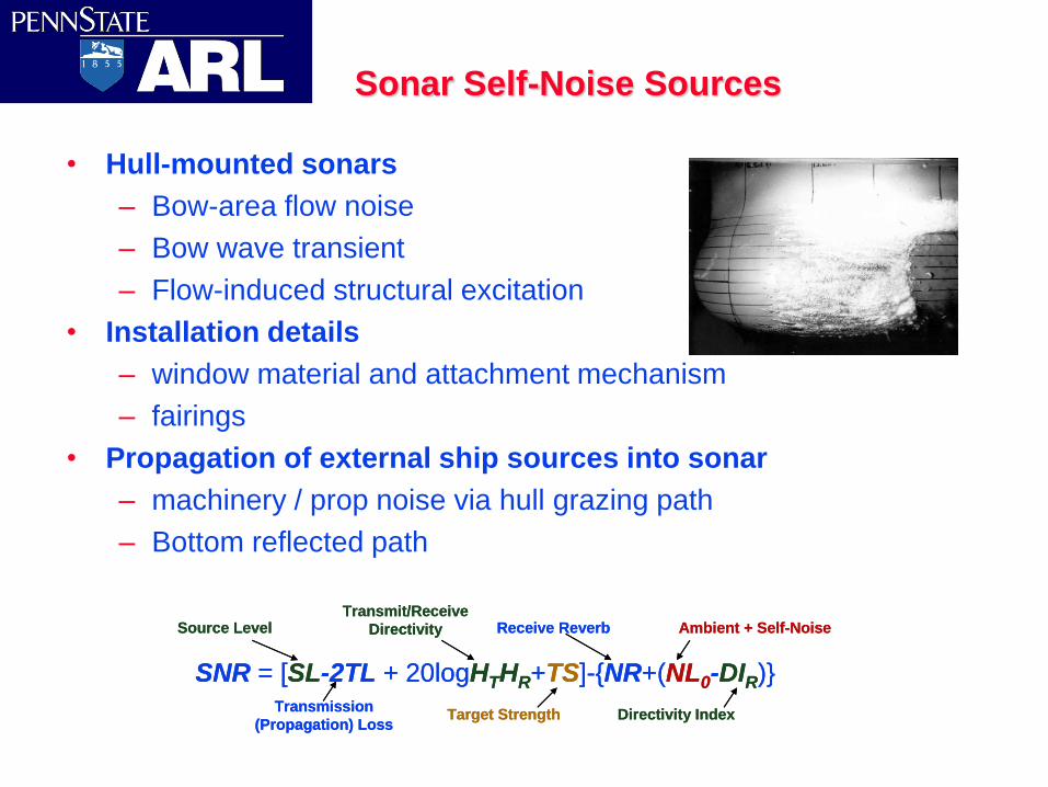
Sonar Self-Noise Sources
• Hull-mounted sonars
– Bow-area flow noise
– Bow wave transient
– Flow-induced structural excitation
• Installation details
– window material and attachment mechanism
– fairings
• Propagation of external ship sources into sonar
– machinery / prop noise via hull grazing path
– Bottom reflected path
SNR = [SL-2TL + 20logHTHR+TS]-{NR+(NL0-DIR)}
Source LevelTransmit/Receive
Directivity
Target StrengthTransmission
(Propagation) Loss
Receive Reverb Ambient + Self-Noise
Directivity Index
SNR = [SL-2TL + 20logHTHR+TS]-{NR+(NL0-DIR)}
Source LevelTransmit/Receive
Directivity
Target StrengthTransmission
(Propagation) Loss
Receive Reverb Ambient + Self-Noise
Directivity Index

Impact - Environmental Noise
• Studies ongoing to assess impact of anthropogenic
noise on marine mammals
– general shipping noise
– Local radiated noise
– Science mission sources
Table from Hildebrand, “Sources of Anthropogenic Sound in the Marine Environment”

ICES Criteria for Fisheries RV’s
From Mitson, “UNDERWATER NOISE OF RESEARCH VESSELS, 1995
• Impact of research vessel noise
on fish surveys
– Based on estimates of “fish
hearing” for various species
– Impact to both acoustic and
catch surveys

Radiated noise measurements in a harbor environment using a vertical
array of omnidirectional hydrophones
Brian Fowler
Graduate Program in Acoustics
Dr. D. Christopher Barber
The Applied Research Laboratory
The Pennsylvania State University
Research Sponsored by ONR 331
1 CAV Workshop, May 14-15, 2012
Overview
• Research Field Test
• Omni-directional measurements
• Beamforming
– Far-field
• Theory
• Measurements
– Near-field
2

Research Testing and Objectives
• Acoustic Research Detachment at Lake Pend Oreille in Bayview, Idaho
• Summer 2010 and 2011
• SEAJET
• In conjunction with near-field acoustic holography (NAH) testing
– Validate NAH estimates
3

Problems with a shallow water harbor environment
• Multipath Environment – Surface reflections
– Bottom reflections
– Reflections off other underwater interfaces
• Near-field Environment – Proximity from hydrophone to source may
prohibit far-field plane wave assumption
4

Hydrophone Array
16”
14 Element Hydrophone Array 5
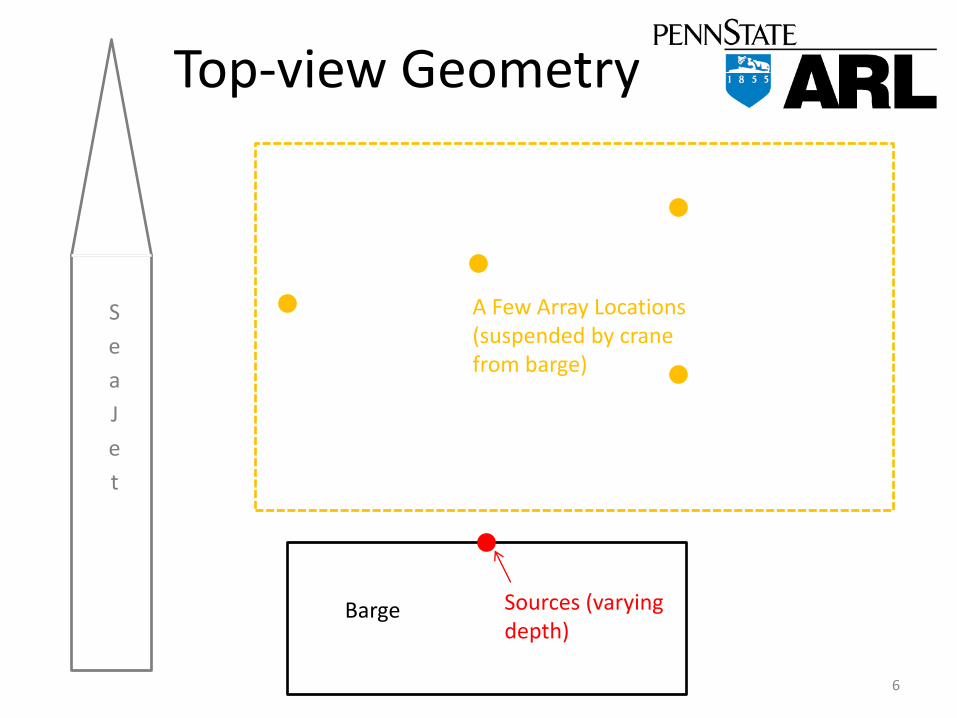
Top-view Geometry
S
e
a
J
e
t
Barge Sources (varying depth)
A Few Array Locations (suspended by crane from barge)
6

Side-view Geometry
7
Range
SeaJet
14
Ele
me
nt
Arr
ay
ITC 1001
J9
Reference Hydrophone
Barge

Omni-directional measurements
9
Ambient Run
Reference Phone
Hydrophone 1

Far-field beamforming theory
p(r,𝜃, 𝑡) = 𝐴
𝑟𝑖′𝑒𝑗(𝜔𝑡−𝑘𝑟
′)
𝑁
𝑖=1
Far field assumptions:
𝑟 ≫ 𝑁 − 1 𝑑 so all 𝑟𝑖 are approximately parallel 1
𝑟𝑖≅1
𝑟 for all 𝑖 where 𝑟 is the distance from array center to source
𝑟 = 𝑟1 −1
2𝑁 − 1 ∆𝑟 where ∆𝑟 = 𝑑 sin 𝜃,
so 𝑟𝑖 = 𝑟1 − (𝑖 − 1)∆𝑟
Kinsler, Frey, Coppens, Sanders. (2000) Line Array [Figure]. In Fundamentals of Acoustics, 4th Ed. pg 195. Hamilton Press 10

Far-field beamforming theory
p(r,𝜃, 𝑡, 𝜃0) =𝐴
𝑟𝑒𝑗(𝜔𝑡−𝑘𝑟)𝑒
−𝑗𝑁−12 𝑘∆𝑟 𝑒𝑗[𝜙𝑖+ 𝑖−1 𝑘∆𝑟]
𝑁
𝑖=1
where 𝜙𝑖 = 𝑖2𝜋
λ𝑑 sin 𝜃
multiplying a 𝑒𝑗𝜙𝑖𝑁𝑖=1 to the unsteered FFT gives us the
beamsteered data in the frequency domain
11

Calculated broadside beams
Changing the steered frequency affects the main lobe width as well as the number and size of the side lobes.
f = 1860 Hz f = 3720 Hz
12

Calculated steered beams
Steering the beam affects the direction in which the main lobe points and also affects the size and direction of the side lobes
f = 1860 Hz, steered to 10 degrees
13

14
Calculated steered beams
14 Element Array steered in the direction of an oncoming plane wave

Far-field beamforming results
15
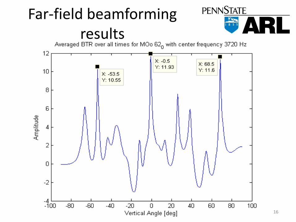
Far-field beamforming results
16

Near-field beamforming theory and application
• Measure from geometric center of array • Remove far-field assumptions and recalculate • This will negate the plane wave assumption and
account for spherical spreading from the source • Vary ranges to find accurate range
17
References • Burdic, William S. Underwater Acoustic System Analysis.
Englewood Cliffs, NJ: Prentice Hall, 1991. Print.
• Kinsler, Lawrence E., Austin R. Frey, Alan B. Coppens, and James V. Sanders. Fundamentals of Acoustics. New York: J. Wiley, 2000. Print.
Acknowledgements
• Carlos Uribe, Wyatt Tyahla, and David Van Hoof (PSU)
• Earl Williams and Nicolas Valdivia (NRL)
18