radiant panel test - faa fire safety · radiant panel test impact of insulation density on approved...
TRANSCRIPT

Radiant Panel Test
Impact of insulation density on approved aerospace insulation and
code compliant films
Authors:Pat Cahill – FAA – RetiredBrian Conover – FAAMonroe Shumate – Johns Manville
Project objective
• Resolve questions for encapsulated systems for low and high insulation densities covered with recognized code compliant films.
• Materials evaluated– Insulation: four types at low, medium and high densities
– Encapsulating film: three types – does not include films used for burn through

Radiant panel test ‐ general parameters
FAA Flame Propagation test (FAR 25.856 a1)Test Method designed to determine the flammability and flame propagation characteristics of thermal/acoustic insulation composites (issued July 31, 2003). This test method is used to evaluate the flammability and flame propagation characteristics of thermal/acoustic insulation when exposed to both a radiant heat source and a flame (see www.fire.tc.faa.gov for additional detail).

Insulation types
Insulation Density• Fiber Glass Low, Medium, High• Polyimide Foam Low(FS)*, Low, Medium,• Melamine Foam Low, Medium• PVDF** – FR Foam Low
*FS = flame seared pretreatment** PVDF = Poly Vinyldene Flouride
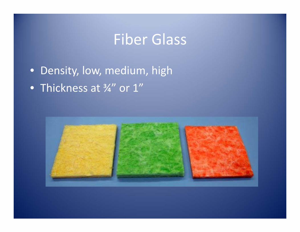
Fiber Glass
• Density, low, medium, high• Thickness at ¾” or 1”

Polyimide Foam
• Density low (fs), low, medium• Thickness 1”
Note: (fs) Darken surface was flame seared as a pre‐treatment before testing

Melamine Foam
• Density, low, medium• Thickness 1”

PVDF Foam
• Density, low• Thickness 1”

Film typesFAA code compliant or approved
• PEEK (polyether ether ketone) film with nylon scrim
• Polyimide film with nylon scrim
• Non‐metallized PVF (polyvinyl fluoride) filmwith nylon scrim

Test Configurations
Film Fiberglass Melamine Polyimide PVDF
Peek Low*Medium High
LowMedium
LowMedium
Low
Polyimide LowMedium High
LowMedium
LowMedium
Low
PVF LowMedium High
LowMedium
Low(fs)**LowMedium
Low
* Product density**fs (flame seared surface – pre‐treatment
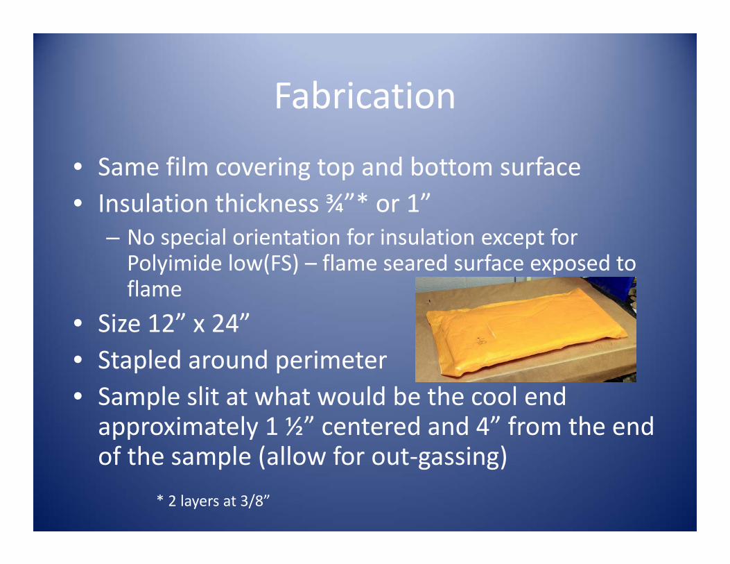
Fabrication
• Same film covering top and bottom surface• Insulation thickness ¾”* or 1”
– No special orientation for insulation except for Polyimide low(FS) – flame seared surface exposed to flame
• Size 12” x 24” • Stapled around perimeter• Sample slit at what would be the cool end approximately 1 ½” centered and 4” from the end of the sample (allow for out‐gassing)
* 2 layers at 3/8”

Test protocol
Equipment setup Test Results
Heat Flux Calibration Initial 1.503 Btu/Sec Sqft Final 1.492 Btu/Sec SqftChamber Temperature Initial 354 °F Final 354 °F
After calibration, tests performed by placing 12” x 24” x 1" samples in the test chamber. Product was exposed to radiant heat and direct flame impingement for 15 seconds as measured by placement then removal of propane ignition source onto the surface of the test sample. Upon removal of ignition source, observe sample for any after flame, burn length and melting of the test specimen.
Test Requirements
There must be no flame propagation beyond 2 inches (51 mm) to the left of the centerline of the pilot flame application.The flame time after removal of the pilot burner may not exceed 3 seconds on any specimen.
Report
Identify and describe specimen being tested At completion of test:
Report any shrinkage or melting of the test specimenReport the Burn lengthReport Extinguishing Time

Radiant panel – general test photos

Test results – Fiber glass
4‐5 samples tested per configurationTest criteria:P = passR = rogue 1 failure of either after flame or flame propagationF = fail – more than one test sample
Insulation Density FilmAfter Flame
Flame Propagation
Fiber glass Low Peek P PFiber glass Low Polyimide P PFiber glass Low PVF P PFiber glass Medium Peek R PFiber glass Medium Polyimide P PFiber glass Medium PVF P PFiber glass High Peek P PFiber glass High Polyimide P PFiber glass High PVF P P

Test resultsMelamine Foam
4‐5 samples tested per configurationTest criteria:P = passR = rogue 1 failure of either after flame or flame propagationF = fail – more than one test sample
Insulation Density FilmAfter Flame
Flame Propagation
Melamine Low Peek P PMelamine Low Polyimide P PMelamine Low PVF F FMelamine Medium Peek P PMelamine Medium Polyimide P PMelamine Medium PVF P P

Test resultsPolyimide foam
4‐5 samples tested per configurationTest criteria:P = passR = rogue 1 failure of either after flame or flame propagationF = fail – more than one test sample
Insulation Density FilmAfter Flame
Flame Propagation
Polyimide Low (fs) PVF P PPolyimide Low Peek P PPolyimide Low Polyimide P PPolyimide Low PVF F FPolyimide Medium Peek P PPolyimide Medium Polyimide P PPolyimide Medium PVF P P
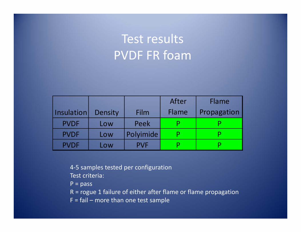
Test resultsPVDF FR foam
4‐5 samples tested per configurationTest criteria:P = passR = rogue 1 failure of either after flame or flame propagationF = fail – more than one test sample
Insulation Density FilmAfter Flame
Flame Propagation
PVDF Low Peek P PPVDF Low Polyimide P PPVDF Low PVF P P

Video of system failure
• Flame propagation – distance• After flame – duration
Original screening ‐non‐code compliant film

Video for system showing compliance• Flame propagation – distance• After flame ‐ duration

General observations as required by FAA system standard
(FAR 25.856a1)
• Insulation system as designed must be tested to show compliance– Materials should not be substituted to show compliance
• Surface characteristics may influence system performance– Smooth vs rough– Pore size or void space – small vs large– Top vs bottom surface– Treated surface ‐ as manufactured or treated before use
• Material reaction to elevated temperatures may influence system performance– Melting– Shrinkage or consolidation– Tearing– Adhesion/cohesion ‐ sticky– Out‐gassing – will or will not ignite

Limitations and concerns• Each individual component may pass FAA test, but must be evaluated as a system; insulation, film, tape, hook & loop, etc. to assure there are no negative effect when combined
• No one combination of materials should be used to show compliance for all configurations
• Care should be taken if an insulation is pre‐treated to ensure compliance – follow manufacturer guidelines– Material orientation for use– Continued compliance to other requirements

Acknowledgements
• Chase Facile• E & H Laminating• Evonik Foams• Hutchinson• Johns Manville• Lamart• Polymer Technologies• Zotefoams