radiant gas brooderradiant gas brooder · this brooder is a self-contained infrared radiant brooder...
TRANSCRIPT

FFFForm No. 43539120 Oct 2010
RADIANT GAS BROODERRADIANT GAS BROODERRADIANT GAS BROODERRADIANT GAS BROODER
MODELS: SRB40EZ-N5 / SRB40EZ-L5 with DIRECT SPARK IGNITION
INSTALLATIONINSTALLATIONINSTALLATIONINSTALLATION
AND OPERATIONAND OPERATIONAND OPERATIONAND OPERATION
INSTRUCTIONSINSTRUCTIONSINSTRUCTIONSINSTRUCTIONS
OWNER/INSTALLEROWNER/INSTALLEROWNER/INSTALLEROWNER/INSTALLER: : : : For your safety this manual must be carefully read before installing, operating or servicing this brooder. This brooder is intended for use with either Natural Gas or Propane Gas. It must be installed by a qualified service person or a licensed contractor in accordance with state and local codes. In the absence of these codes, the installation must conform to the National Fuel Gas Code ANSI Z223.1 (latest edition) also know a NFPA54 or the CAN/CGA-B149.1/2 Installation Code in Canada. �WARNINGWARNINGWARNINGWARNING:::: Improper installation, adjustment, alteration, service or maintenance can cause injury, property
damage or death. Refer to this manual. For assistance or additional information, consult a qualified installer, service agency or the gas supplier. INSPECTINSPECTINSPECTINSPECT all combustion air openings into the building and, if necessary, clear as they become blocked by litter, dust, feathers or other matter. INSPECTINSPECTINSPECTINSPECT and clean the brooder filters on a regular basis to allow proper brooder operation.
FOR YOUR SAFETY:FOR YOUR SAFETY:FOR YOUR SAFETY:FOR YOUR SAFETY: EXHAUST FANS MUSTMUSTMUSTMUST be operating on an appropriate cycle when brooders are operating to avoid a high concentration of carbon monoxide. When used without fresh air, this brooder may give off carbon monoxide, an odorless and poisonous gas. CARBON MONOXIDE POISONING MAY LEAD TO DEATH.CARBON MONOXIDE POISONING MAY LEAD TO DEATH.CARBON MONOXIDE POISONING MAY LEAD TO DEATH.CARBON MONOXIDE POISONING MAY LEAD TO DEATH. Early signs of carbon monoxide poisoning resemble the flu with headaches, dizziness and nausea. If you experience these signs, GET FRESH AIR IMMEDIATELY!GET FRESH AIR IMMEDIATELY!GET FRESH AIR IMMEDIATELY!GET FRESH AIR IMMEDIATELY! Have the brooders serviced as soon as possible and check the ventilation in the house.
These brooders are designed for agricultural applications and may operate with the use of either Natural Gas or Liquid Propane (LP) Gas. Check the brooder’s nameplate to determine the correct gas type before proceeding with installation.
IF YOU SMELL GASIF YOU SMELL GASIF YOU SMELL GASIF YOU SMELL GAS::::
!!!! DO NOTDO NOTDO NOTDO NOT try to light any appliance.
!!!! DO NOTDO NOTDO NOTDO NOT touch any electrical switch; do not use any
telephone in your building.
!!!! IMMEDIATELYIMMEDIATELYIMMEDIATELYIMMEDIATELY call your gas supplier from a neighbor's
telephone. Follow the gas supplier's instructions. If you cannot reach your gas supplier, call the fire department.
DO NOT DO NOT DO NOT DO NOT store or use gasoline or other flammable vapors and liquids in the vicinity of this or any other appliance.
SAVE THIS MANUALSAVE THIS MANUALSAVE THIS MANUALSAVE THIS MANUAL FOR FUTURE REFERENCE.FOR FUTURE REFERENCE.FOR FUTURE REFERENCE.FOR FUTURE REFERENCE.
FOR YOUR SAFETYFOR YOUR SAFETYFOR YOUR SAFETYFOR YOUR SAFETY
Form No. 43539120 Oct 2010 –1–
TABLE OF CONTENTSTABLE OF CONTENTSTABLE OF CONTENTSTABLE OF CONTENTS
Section Description Page
1) GENERAL INFORMATION ............................................................................................ 1 2) BROODER SPECIFICATIONS ....................................................................................... 1 3) BROODER CONTROL DESCRIPTION .......................................................................... 2 3a) BROODER ACCESSORIES .......................................................................................... 2 4) BROODER ASSEMBLY ................................................................................................. 4 4a) GAS VALVE WIRE CONNECTIONS .............................................................................. 7 5) MINIMUM CLEARANCES TO COMBUSTIBLES .......................................................... 8 6) BROODER INSTALLATION ........................................................................................... 8 7) GAS CONNECTIONS ..................................................................................................... 9 7a) INSTRUCTIONS FOR TESTING OF GAS LEAKS AND PROPER GAS PRESSURE ... 11 7b GAS PIPE SIZING EXAMPLE ....................................................................................... 13 8) ELECTRICAL CONNECTIONS ....................................................................................... 14 9) LIGHTING AND SHUTDOWN INSTRUCTIONS ............................................................ 17
10) VENTILATION ................................................................................................................ 18 11) CLEANING AND ANNUAL MAINTENANCE ................................................................. 18 12) TROUBLESHOOTING .................................................................................................... 21 13) REPLACEMENT PARTS GUIDE.................................................................................... 23
1.1.1.1. GENERAL INFORMATIONGENERAL INFORMATIONGENERAL INFORMATIONGENERAL INFORMATION
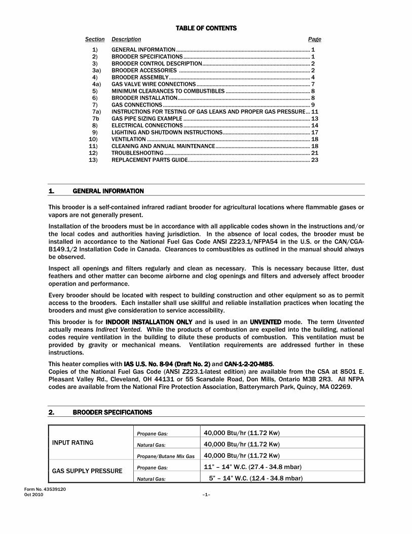
This brooder is a self-contained infrared radiant brooder for agricultural locations where flammable gases or vapors are not generally present. Installation of the brooders must be in accordance with all applicable codes shown in the instructions and/or the local codes and authorities having jurisdiction. In the absence of local codes, the brooder must be installed in accordance to the National Fuel Gas Code ANSI Z223.1/NFPA54 in the U.S. or the CAN/CGA-B149.1/2 Installation Code in Canada. Clearances to combustibles as outlined in the manual should always be observed. Inspect all openings and filters regularly and clean as necessary. This is necessary because litter, dust feathers and other matter can become airborne and clog openings and filters and adversely affect brooder operation and performance. Every brooder should be located with respect to building construction and other equipment so as to permit access to the brooders. Each installer shall use skillful and reliable installation practices when locating the brooders and must give consideration to service accessibility. This brooder is for INDOOR INSTALLATION ONLY INDOOR INSTALLATION ONLY INDOOR INSTALLATION ONLY INDOOR INSTALLATION ONLY and is used in an UNVENTED UNVENTED UNVENTED UNVENTED mode. The term Unvented actually means Indirect Vented. While the products of combustion are expelled into the building, national codes require ventilation in the building to dilute these products of combustion. This ventilation must be provided by gravity or mechanical means. Ventilation requirements are addressed further in these instructions. This heater complies with IIIIAS U.S. No. 8AS U.S. No. 8AS U.S. No. 8AS U.S. No. 8----94 (Draft No. 2)94 (Draft No. 2)94 (Draft No. 2)94 (Draft No. 2) and CANCANCANCAN----1111----2222----20202020----M85M85M85M85. Copies of the National Fuel Gas Code (ANSI Z223.1-latest edition) are available from the CSA at 8501 E. Pleasant Valley Rd., Cleveland, OH 44131 or 55 Scarsdale Road, Don Mills, Ontario M3B 2R3. All NFPA codes are available from the National Fire Protection Association, Batterymarch Park, Quincy, MA 02269.
2.2.2.2. BROODER SPECIFICATIONSBROODER SPECIFICATIONSBROODER SPECIFICATIONSBROODER SPECIFICATIONS
INPUT RATING
Propane Gas: 40,000 Btu/hr (11.72 Kw)
Natural Gas: 40,000 Btu/hr (11.72 Kw)
Propane/Butane Mix Gas 40,000 Btu/hr (11.72 Kw)
GAS SUPPLY PRESSURE Propane Gas: 11” – 14” W.C. (27.4 - 34.8 mbar)
Natural Gas: 5” – 14” W.C. (12.4 - 34.8 mbar)

Form No. 43539120 –2– Oct 2010
Propane/Butane Mix Gas 11” – 14” W.C. (27.4 - 34.8 mbar)
MANIFOLD PRESSURE
Propane Gas: 10” W.C. (24.9 mbar)
Natural Gas: 4” W.C. (10.0 mbar)
Propane/Butane Mix Gas 10” W.C. (24.9 mbar)
ORIFICE SIZE
Propane Gas: 1.9mm (.0748”)
Natural Gas: #33 (.1130”)
Propane/Butane Mix Gas #50 (.0700”)
MOUNTING HEIGHT 60” - 72” (1520mm – 1830mm)
BROODER SPACING 25’ – 40’ (7.6m – 12.2m)
BROODER SIZE Canopy Diameter: 35” (890mm)
Brooder Height: 18” (460mm)
WEIGHT 27 lbs (12 kg)
VENTILATION REQUIRED Per Brooder: 200 CFM (340 m3/hr)
GAS CONSUMPTION
Propane Gas: 0.43 GPH (1.63 L/hr)
Natural Gas: 0.40 Therm (42.2 MJ/Hr)
Propane/Butane Mix Gas 0.43 GPH (1.63 L/Hr)
ELECTRICAL SUPPLY 24 VAC, 1 Ph, 60Hz, 0.8A
3.3.3.3. BROODER CONTROL BROODER CONTROL BROODER CONTROL BROODER CONTROL DESCRIPTIONDESCRIPTIONDESCRIPTIONDESCRIPTION
Brooder Controls No. 5555 and 5B5B5B5B are designed for single or multi-zone installations using one or more thermostats. A Zone Control (available as an accessory, Part No.43619050) is required to provide a 24-Volt power supply to each brooder. The burner is controlled with a Direct Spark Ignition (DSI) switch, which is designed to provide 100 percent gas shut off of the main valve in the event that the main burner flame is not sensed.
3a.3a.3a.3a. BROODER ACCESSORIESBROODER ACCESSORIESBROODER ACCESSORIESBROODER ACCESSORIES
A) Zone Control Panel Model ZCP22, Part No. 43619050 This is a power supply control which utilizes a 375VA transformer to provide the required 24VAC for single or multiple groups (zones) of brooders. Refer to electrical section of manual for allowable heater quantities per transformer.
B) Transformer Replacement – 375VA 120/240VAC 24VAC, Part No. 30222070
Zone Control Power Supply(with 375VA Transformer)
Transformer120/240 - 24VAC375VA

Form No. 43539120 Oct 2010 –3–
C) Thermostat – Environmental (EW-4-20), Part No. 30525010
Ratings: SPDT 120/240VAC, 16A Full Load Temperature range: -40 Deg. F to 104 Deg. F +/- 2.5 Deg.F Differential Housing: Watertight ABS plastic meets NEMA 4x and NEC Article 547-4 requirements for use in harsh environments. Adjustable dial allows thermostat to be recalibrated.
D) Thermostat – Individual, Part No. 43317050 Temperature range: 58 Deg. F to 122 Deg. F with ten (10) temperature scale ranges. The thermostat is used to control individual brooders for Turkey heating applications. Includes Mears thermostat, plastic enclosure, bracket and screws to mount to Honeywell #VR8205 gas valve.
E) Hose Kits – No. 5No. 5No. 5No. 5 ControlsControlsControlsControls: 6FT Hose with 3/8” swivel female flare fittings and 6” spring, Part No. 30522061 10FT Hose with 3/8” swivel female flare fittings and 6” spring, Part No. 30522101
Each kit includes (2) 45 deg. flare fittings (3/8” tube x 1/2” NPT) for connection to main gas valve and manual shut-off valve.
Hose Kits - No. 5BNo. 5BNo. 5BNo. 5B ControlsControlsControlsControls:
6FT Hose with 3/8” swivel female flare fittings and 6” spring, Part No. 30522060
10FT Hose with 3/8” swivel female flare fittings and 6” spring, Part No. 30522100
Each kit includes (1) 45 deg. flare fitting (3/8” tube x 1/2” NPT) for connection to manual shut-off valve and (1) 45 deg. flare fitting (3/8” tube x 3/8” NPT for connection to main gas valve.
F) Manual Gas Shut-Off Ball Valve – 1/2”NPT, Part #30285000
G) Wire Brush – Long, Part #43295020 Wire Brush – Short, Part #43295010
EnvironmentalThermostat
Turkey Thermostat
Manual GasShut-Off Valve
Wire Brush - Long(for emitter)
Wire Brush - Short(for burner & pilot)
45 Flare Fitting3/8� Tube x 3/8�NPT
Hose Assembly(with 6� Spring)
45 Flare Fitting3/8� Tube x 1/2�NPT
45 Flare Fitting3/8� Tube x 1/2�NPT

Form No. 43539120 –4– Oct 2010
4.4.4.4. BROODER ASSEMBLBROODER ASSEMBLBROODER ASSEMBLBROODER ASSEMBLYYYY
1. Make sure that all components are present before assembling the brooder.
Qty.Qty.Qty.Qty. DescriptionDescriptionDescriptionDescription Qty.Qty.Qty.Qty. DescriptionDescriptionDescriptionDescription (1) Control Arm (1) Emitter Assembly (1) Safety Pan (1) Ignition Control Assembly (1) Canopy (1) Box Support Bracket (1) Burner Base (1) Low Profile Hanging Bracket (Kit) (1) Manifold Support Bracket & Clamp (1) Fastener Kit
The Fastener Kit contains all the nuts, bolts and washers required for brooder assembly. You will need two (2) crescent wrenches and a flat-bladed screwdriver for brooder assembly.
2. Place the Low Profile Hanging Bracket onto the Canopy as shown. Secure the bracket to the center of
the Canopy with a screw, nut and washer from the Fastener Kit. Assemble the eyebolt to the hanging bracket with nuts and washers. Align the hanging bracket with the two (2) holes located at the edge of the Canopy. See Figure 1.
3. Position the Emitter Assembly on a table with the mounting studs facing upwards. 4. Place the Canopy over the Emitter Assembly so that the mounting studs pass through the three (3) holes
in the Canopy and the hole in the hanging bracket. Secure the Canopy and the hanging bracket to the mounting studs using nuts and flat washers as shown. See Figure 1.
Eyebolt with 1/4-20Nuts & M8 Washers
ReflectorCanopy
#12 Screw, Nut& M8 Washer
EmitterAssembly
AlignmentHoles
1/4-20 Hex Nuts& M8 Washers
Low ProfileHanging Bracket
FIGURE 1
Form No. 43539120 Oct 2010 –5–
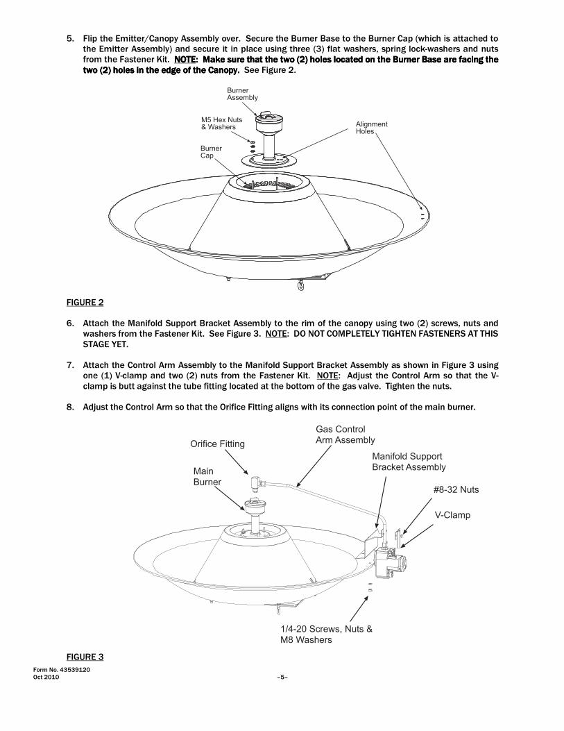
5. Flip the Emitter/Canopy Assembly over. Secure the Burner Base to the Burner Cap (which is attached to the Emitter Assembly) and secure it in place using three (3) flat washers, spring lock-washers and nuts from the Fastener Kit. NOTENOTENOTENOTE:::: Make sure that the two (2)Make sure that the two (2)Make sure that the two (2)Make sure that the two (2) holesholesholesholes located on the Burlocated on the Burlocated on the Burlocated on the Burner Base are facing the ner Base are facing the ner Base are facing the ner Base are facing the two (2) holes in the edge of the Canopy. two (2) holes in the edge of the Canopy. two (2) holes in the edge of the Canopy. two (2) holes in the edge of the Canopy. See Figure 2.
BurnerAssembly
AlignmentHoles
M5 Hex Nuts& Washers
BurnerCap
FIGURE 2 6. Attach the Manifold Support Bracket Assembly to the rim of the canopy using two (2) screws, nuts and
washers from the Fastener Kit. See Figure 3. NOTE: DO NOT COMPLETELY TIGHTEN FASTENERS AT THIS STAGE YET.
7. Attach the Control Arm Assembly to the Manifold Support Bracket Assembly as shown in Figure 3 using
one (1) V-clamp and two (2) nuts from the Fastener Kit. NOTE: Adjust the Control Arm so that the V-clamp is butt against the tube fitting located at the bottom of the gas valve. Tighten the nuts.
8. Adjust the Control Arm so that the Orifice Fitting aligns with its connection point of the main burner.
Orifice Fitting
MainBurner
Gas ControlArm Assembly
Manifold SupportBracket Assembly
#8-32 Nuts
V-Clamp
1/4-20 Screws, Nuts &M8 Washers
FIGURE 3
Form No. 43539120 –6– Oct 2010
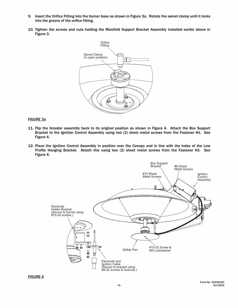
9. Insert the Orifice Fitting into the burner base as shown in Figure 3a. Rotate the swivel clamp until it locks into the groove of the orifice fitting.
10. Tighten the screws and nuts holding the Manifold Support Bracket Assembly installed earlier above in
Figure 3.
OrificeFitting
Swivel Clamp(in open position)
FIGURE 3a 11. Flip the brooder assembly back to its original position as shown in Figure 4. Attach the Box Support
Bracket to the Ignition Control Assembly using two (2) sheet metal screws from the Fastener Kit. See Figure 4.
12. Place the Ignition Control Assembly in position over the Canopy and in line with the holes of the Low
Profile Hanging Bracket. Attach this using two (2) sheet metal screws from the Fastener Kit. See Figure 4.
Box SupportBracket
#10 SheetMetal Screws
#8 SheetMetal Screws
IgnitionControlAssembly
Safety Pan#10-32 Screw &M5 Lockwasher
Electrode andIgnition Cable(Secure to bracket using#8-32 screws & locknuts.)
ElectrodeHolder Bracket(Secure to burner using#10-24 screws.)
FIGURE 4

Form No. 43539120 Oct 2010 –7–
13. Attach the electrode bracket to the Burner Base using two (2) screws from the Fastener Kit. Attach the electrode to the bracket using two (2) machine screws and nuts from the Fastener Kit. Secure the ignition cable to the gas control arm using the wire ties included in the Fastener Kit.
14. Attach the Safety Pan to the Gas Control Arm, as shown in Figure 4, using one (1) screw and (1) spring
lock-washer from the Fastener Kit. The brooder is now ready for installation.
�WARNING: ONCE THE BROODER IS ASSEMBLED AND BEFORE IT IS FIRST FIRED, YOU MUST CHECK FOR
GAS LEAKS! USE A SOAP AND WATER SOLUTION AND APPLY AT ORIFICE FITTING AND FIELD CONNECTION AT THE GAS VALVE.
4a.4a.4a.4a. GAS VALVE WIRE CONNECTIONSGAS VALVE WIRE CONNECTIONSGAS VALVE WIRE CONNECTIONSGAS VALVE WIRE CONNECTIONS
1. Locate the two (2) blue wires from the ignition Control Assembly. Refer to the wiring diagram located in
Section 8, Electrical Connections. 2. Connect the wires to terminals MV MV MV MV of the gas valve of control no. control no. control no. control no. 5555 or to terminals 1111 and 4444 of control no.control no.control no.control no.
5B5B5B5B. See Figure 5.
Wire ConnectionsTerminals MV
Wire ConnectionsTerminals 1 & 4
CONTROL NO. 5GAS VALVE #VR8205M
CONTROL NO. 5BGAS VALVE #25M12
1234
14
FIGURE 5

Form No. 43539120 –8– Oct 2010
5.5.5.5. MINIMUM CLEARANCES TO COMBUSTIBLESMINIMUM CLEARANCES TO COMBUSTIBLESMINIMUM CLEARANCES TO COMBUSTIBLESMINIMUM CLEARANCES TO COMBUSTIBLES
Minimum clearances to combustible materials shall be measured from the outer surface of the canopy as shown in the following table:
MINIMUM CLEARANCES TO COMBUSTIBLES
Sides: Below: Above:
36” (915mm) 48” (1220mm) 18” (460mm)
SIDESIDE
ABOVE
BELOW
6.6.6.6. BROODER INSTALLATIONBROODER INSTALLATIONBROODER INSTALLATIONBROODER INSTALLATION
1. Locate brooders approximately 25’ to 40’ (8m to 12m) apart, in a row, as needed for bird comfort and
building heat loss. If more than one row is desired, stagger rows for best heat distribution. Attach the Chain Kit (optional) to the top of the brooder Canopy. NOTENOTENOTENOTE:::: Make sure that the large hook (short chain length) is secured to the hanging lug on the side of the brooder closest to the gas valve.
2. Suspend the brooder at the desired height above the floor (litter) level, normally 60” to 72” (1520mm to
1830mm). For brooders connected to a winch (to allow for adjustment of brooder height), connect each Chain Kit using a chain or cable suitable for the weight of each brooder. DO NOT USE ROPE.... Size the winch and cable so that it is capable of handling the total weight of all brooders and gas piping involved. NOTENOTENOTENOTE: : : : Connect a safety chain to each brooder and anchor it to the house structure above each brooder to prevent it from falling onto the litter if the cable/chain breaks or the winch fails. THE GAS HOSE SHOULD NEVER BE USED AS A SAFETY CHAIN!
3. Connect the gas line and electrical supply (if required) to each brooder as outlined in Sections 7 and 8.
NOTENOTENOTENOTE:::: After connection of the gas line, make sure that the brooder is suspended with the control side approximately ½” (13mm) below the other side of the brooder to prevent hot products of combustion from damaging the gas control valve.
FIGURE 5a

Form No. 43539120 Oct 2010 –9–
Suspension chain orcable attached to winchsystem.
Safety chain orcable attached tohouse ceiling structure.(provide 2" to 6" of slack)
Ceiling Structure
7.7.7.7. GAS CONNECTIONSGAS CONNECTIONSGAS CONNECTIONSGAS CONNECTIONS
1. Gas piping for the house must be sized to be capable of satisfying the entire demands of the house
should all equipment be operating at the same time. Please use Table 1 (taken from the National Fuel Gas Code) for the sizing of piping for the house. An example using this table is shown.
2. Connect to the supply tank or manifold in accordance with the latest edition of the National Fuel Gas
Code (ANSI Z223.1) and/or local codes. Authorities having jurisdiction should be consulted before the installation is made. Refer to the latest edition of CAN/CGA B.149-1/2 Installation Codes for Gas Burning Appliances and Equipment in Canada.
3. Pipe joint compounds must be resistant to the action of liquefied petroleum (LP) gases. 4. Gas connections to individual brooders shall be made using flexible gas connectors, or they can utilize
rubber hosing suitable for LP gas usage (to allow movement of the brooders for cleaning, etc.). Check with the authorities having jurisdiction and/or local codes prior to choosing an individual gas connection method.
5. Connection to a new installation with accessoryaccessoryaccessoryaccessory hose and fittings is shown below:
WARNINGWARNINGWARNINGWARNING
FIRFIRFIRFIRE HAZARDE HAZARDE HAZARDE HAZARD
A safety chain must be connected from the hanging bracket to a fixed part of the building structure directly above the brooder. The safety chain will prevent the brooder from falling to the floor in the event that the main suspension system fails Failure to follow these instructions may result in death, serious injury or property damage
!
FIGURE 5b

Form No. 43539120 –10– Oct 2010
Apply LP and Natural Gasapproved thread sealant
1
2
3
2
Control No. 5
3a
2a
Control No. 5B
X FIRE HAZARD
Tighten flexible gas hose and components securely.
Flexible gas hoses must be installed without any twists orkinks in them. DO NOT allow the hose to touch any portionof the brooder canopy during operation.
Failure to do so may result in death, serious injury or propertydamage.
Item Number Part Number Description Qty
1 30285000 VALVE,MANUAL BALL 1/2" 1
2 30241010 MALE FTG 45FLARE 3/8TUBEx1/2MPT 2
2a 30241000 MALE FTG 45FLARE 3/8TUBEx3/8MPT 1
3 30523060 HOSE,3/8IDx6FT with 3/8"F SWIVEL FITTINGS 1
3a 30523100 HOSE,3/8IDx10FT with 3/8"F SWIVEL FITTINGS 1
Make sure connection is secure before turning on the gas. See section 7a for procedures to test for gas leaks before putting the brooders into operation.
FIGURE 5c

Form No. 43539120 Oct 2010 –11–
6. It is strongly recommended that a field installed manual shut-off valve be installed in the gas piping to each brooder. This will allow service of individual brooders without having to shut down the entire gas supply system. When installing the gas line, it is recommended to connect a sediment trap (shown right) in the gas line at a point before the gas line enters the house. This trap or “drip leg” acts to trap impurities and water that can condense out of the gas. It helps to keep impurities from entering the appliance and causing potential damage to gas valves, etc. Periodically remove the cap from the drip leg and drain any accumulation of dirt and/or water.
7. After all gas connections and adjustments are made, check all gas
connections for leaks (not just the gas connections at the brooders) using a heavy soapsuds solution or by using one of the methods listed in Appendix D of the National Fuel Gas Code. ����WARNINGWARNINGWARNINGWARNING: : : : DO NOT USE AN OPEN FLAME OF ANY KIND TO TEST FOR LEAKS!
8. It is recommended that a pressure gauge be installed at the end of the gas piping run to allow you to check the gas supply pressure in the system. This needs to be capable of accurately measuring in units of inches of water column or mbar.
7a.7a.7a.7a. INSTRUCTIONS FOR TESTING FOR GAS LEAKS AND PROPER GAS PRESSUREINSTRUCTIONS FOR TESTING FOR GAS LEAKS AND PROPER GAS PRESSUREINSTRUCTIONS FOR TESTING FOR GAS LEAKS AND PROPER GAS PRESSUREINSTRUCTIONS FOR TESTING FOR GAS LEAKS AND PROPER GAS PRESSURE
����WARNINGWARNINGWARNINGWARNING: DO NOT OMIT THESE TESTS: DO NOT OMIT THESE TESTS: DO NOT OMIT THESE TESTS: DO NOT OMIT THESE TESTS!!!!
TESTING THE INSTALLATION FOR GAS LEAKS: 1. Inspect all connections and appliance valves to be sure connections are wrench-tight and that all
appliance valves are closed. 2. Connect a low-pressure test set to the low pressure piping system just upstream of the appliance
regulators and control. NOTE: A dry gauge manometer is available as an accessory (Part No. 43649000).
3. Fully open the LP gas container valve slowly to pressurize the piping system. Once the system is pressurized and stabilized, close the container valve tightly.
4. Observe the indicated pressure on the low-pressure test set gauge. This reading should be approximately equivalent to the set delivery pressure of the final stage regulator. Now, slowly open one burner valve on the appliance to vent off just enough gas to reduce the pressure on the test gauge by 1” water column, then close the burner or pilot valve.
If the pressure remains unchanged on the gauge for at least 10 minutes, the system can be assumed leak-tight. If a drop in pressure does occur, it indicates a leak in the system. If the pressure drop occurs, check the joints, connectors, and other possible points of leakage with an approved, high-quality leak detection solution. NEVER USE A MATCH OR OPEN FLAME TO CHECK FOR LEAKS. Once a leak has been located and repaired, repeat Steps 3 and 4 above. If there is an increase in pressure, it indicated that the LP gas container valve is not shut off tightly. Shut off the valve tightly and repeat Step 4 above. NOTE: Do not expose final stage piping to excessive heat or direct sunshine during the leak test. Pressure Do not expose final stage piping to excessive heat or direct sunshine during the leak test. Pressure Do not expose final stage piping to excessive heat or direct sunshine during the leak test. Pressure Do not expose final stage piping to excessive heat or direct sunshine during the leak test. Pressure builbuilbuilbuildddd----up in the line due to heat may compensate for pressure loss due to leaks. This will prevent the gauge up in the line due to heat may compensate for pressure loss due to leaks. This will prevent the gauge up in the line due to heat may compensate for pressure loss due to leaks. This will prevent the gauge up in the line due to heat may compensate for pressure loss due to leaks. This will prevent the gauge reading from indicating system leaks.reading from indicating system leaks.reading from indicating system leaks.reading from indicating system leaks. �WARNING: Gas Pressure Testing is to be performed only by qualified personnel.
FIGURE 5d
To Brooders
GasSupply
Inlet
TeeFitting
PipeNipple
PipeCap
3� Minimum
SEDIMENT TRAP(DRIP LEG)

Form No. 43539120 –12– Oct 2010
CHECK GAS INLET (SUPPLY) PRESSURE: 1. Be sure the valve is in the “OFF” position before removing the pressure tap plug at the valve. Connect a
low-pressure test set (water manometer or dry gauge) to the 1/8” NPT Inlet Pressure Tap connection (see Figure 6). Turn the valve to the “ON” position. DO NOT EXCEED THE PRESSURES SHOWN IN THE GAS PRESSURE TABLE.
2. Turn the valve back to the “OFF” position before removing the test set and replacing the plug. Repeat the gas leak test at the plug.
Gas Inlet
OF
F
ON
1/8" NPT InletPressure Tap with 3/16"Hex Allen Wrench Plug
Pressure RegulatorAdjustment(under cap screw)
Gas ControlKnob
1/8" NPT OutletPressure Tap with 3/16"Hex Allen Wrench Plug
24VConnection(MV Terminals)
CONTROL NO. 5GAS VALVE #VR8205M
CONTROL NO. 5BGAS VALVE #25M12 & 25M18
1/8" NPT OutletPressure Tap with 3/16"Hex Allen Wrench Plug(typical opposite side)
Gas Inlet
123
4
14
24VConnection(1 & 4 Terminals)
Pressure RegulatorAdjustment(under cap screw)
Not included on #25M18Flip-Flop Valves
1/8" NPT InletPressure Tap with 3/16"Hex Allen Wrench Plug(this side only)
*CHECK GAS OUTLET (MANIFOLD) PRESSURE: 1. Be sure that the valve is in the “OFF” position before removing the pressure tap plug at the valve. With
the main burner operating, check the manifold pressure using a lower-pressure test set connected to the 1/8” NPT Outlet Pressure Tap, (see Figure 6). Gas valves are combination valves with built-in appliance regulators. These regulators are factory set and should not require adjustment. They should provide the correct manifold pressure at the varying supply pressures noted in the Gas Pressure Table below. DO NOT EXCEED THE PRESSURES SHOWN IN THE GAS PRESSURE TABLE.
2. If manifold gas pressure adjustment is required, remove the cover screw (see Figure 6). Using a small screwdriver, turn the adjusting screw clockwise � to increase or counter clockwise � to decrease the gas pressure to the burner.
3. Turn the valve back to the “OFF” position before removing the manometer and replacing the plug. Repeat the gas leak test at the plug.
GAS PRESSURE TABLE
BROODER MODEL GAS TYPE
MANIFOLD PRESSURE
SUPPLY PRESSURE
Minimum� Maximum
SRB40EZ-N5 Natural Gas 4” WC (10.0 mbar) 5” WC (12.4 mbar) 14” WC (34.9 mbar)
SRB40EZ-L5 Propane Gas 10” WC (24.9 mbar) 11” WC (27.4 mbar) 14” WC (34.9 mbar)
Propane/Butane Mix Gas 10” WC (24.9 mbar) 11” WC (27.4 mbar) 14” WC (34.9 mbar)
� Minimum permissible gas supply pressure for the purpose of input adjustment.
****Note:Note:Note:Note: The control no. 5B may be equipped with gas valve #25M18 (not shown) having a FlipFlipFlipFlip----FlopFlopFlopFlop convertible convertible convertible convertible regulator regulator regulator regulator which is for conversion from LP to Nat Gas (or vice-versa) and cannot be field adjusted for outlet (manifold) pressure.
FIGURE 6

Form No. 43539120 Oct 2010 –13–
REGULATOR LOCK-UP AND LEAKAGE: After the leak testing and delivery pressure tests have proven satisfactory, the regulator lock-up and leakage test may be performed. The lock-up pressure of the final stage regulator should be slightly higher than, but not more than, 120% of the set delivery pressure. For example, on a delivery pressure setting of 12” water column, the maximum allowable lock-up pressure is 14.4” water column. To perform the lockTo perform the lockTo perform the lockTo perform the lock----up and leakage test, follow these stepup and leakage test, follow these stepup and leakage test, follow these stepup and leakage test, follow these steps:s:s:s: 1. With the LP tank valve fully open, shut off all appliance valves so there is no demand for gas. 2. A slight rise in pressure will occur under these conditions. This rise should be no more than 120% of the
delivery pressure. This is the lock up pressure. NOTENOTENOTENOTE:::: A quick rise in pressure above the allowable lock-up point could indicate undersized piping, a worn seat disc or foreign material in the seating area. This This This This condition must becondition must becondition must becondition must be corrected before putting the system in service.corrected before putting the system in service.corrected before putting the system in service.corrected before putting the system in service.
3. Continue the test for five minutes or more. If a creeping rise in pressure is noticed, the final stage regulator seat is not closing off properly. The regulator must be replaced or repaired, and the system retested, before putting the system in service.
7b.7b.7b.7b. GAS PIPE SIZING EXAMPLEGAS PIPE SIZING EXAMPLEGAS PIPE SIZING EXAMPLEGAS PIPE SIZING EXAMPLE
House Size: 40’ x 400’
Brooder Quantity: 14
Individual Brooder Capacity: 40,000 Btu/hr
Second Stage Regulator Pressure: 14” W.C.
Operating Pressure: 11”W.C., LP gas with all brooders operating
STEP 1STEP 1STEP 1STEP 1. Gas should be run at high pressure from the LP tank to the second stage regulator at the house. Using the above house configuration example, calculate the gas pipe sizing. First, calculate the total distance from the second stage regulator to the furthest brooder. In Figure 9 above, that distance equals 202’ (20’ + 182’). Using Table 1, look up the row for 200’ and select the smallest pipe size that has the capacity for the flow of the end brooder (40,000). The smallest pipe size is ½” with a capacity of up to 58,000 Btu/hr over 200’. STEP 2STEP 2STEP 2STEP 2. Calculate the distance from the second furthest brooder to the secondary regulator. In the example, that distance equals 174’. Using Table 1, look up the row for 174’. As 174’ is not listed, you will use the next distance up, in this case, 200’. Then select the smallest pipe size that has the capacity for the flow of both the furthest (#7) and second furthest (#6) brooders, which combines to 80,000 Btu/hr. The smallest pipe size is ¾” with a capacity of up to 120,000 Btu/hr over 200’. Repeat this process for each brooder until you reach the Tee. Table 2 shows the completed example. STEP 3STEP 3STEP 3STEP 3. At the Tee, calculate the total distance to the secondary regulator. In this example, that equals 20’. Using Table 1, look up the row for 20’ and select he smallest pipe size that has the capacity for the flow of all the brooders connected to the pipe system (560,000). The smallest pipe size is 1” with a capacity of up to 788,0000 Btu/hr over 20’.
Figure 7Figure 7Figure 7Figure 7

Form No. 43539120 –14– Oct 2010
TABLE 1TABLE 1TABLE 1TABLE 1. -------- LP Gas Pipe Sizing Between Single or Second Stage Regulator and Brooders Per ANSI Z223.1 National Fuel Gas CodeLP Gas Pipe Sizing Between Single or Second Stage Regulator and Brooders Per ANSI Z223.1 National Fuel Gas CodeLP Gas Pipe Sizing Between Single or Second Stage Regulator and Brooders Per ANSI Z223.1 National Fuel Gas CodeLP Gas Pipe Sizing Between Single or Second Stage Regulator and Brooders Per ANSI Z223.1 National Fuel Gas Code----1992199219921992
Tubing Size, O.D. Type L Nominal Pipe Size, I.D. Schedule 40
3/8”3/8”3/8”3/8” 1/2”1/2”1/2”1/2” 5/8”5/8”5/8”5/8” 3/4”3/4”3/4”3/4” 7/8”7/8”7/8”7/8” 1111----1/8”1/8”1/8”1/8” 1/1/1/1/2”2”2”2” 3/4”3/4”3/4”3/4” 1”1”1”1” 1111----1/4”1/4”1/4”1/4” 1111----1/2”1/2”1/2”1/2” 2”2”2”2” 3”3”3”3” 4”4”4”4”
10 Ft.10 Ft.10 Ft.10 Ft. 39 92 199 329 501 935 291 608 1,146 2,353 3,525 6,789 19,130 39,018
20 Ft.20 Ft.20 Ft.20 Ft. 26 62 131 216 346 630 200 418 788 1,617 2,423 4,666 13,148 26,817
30 Ft.30 Ft.30 Ft.30 Ft. 21 50 107 181 277 500 161 336 632 1,299 1,946 3,747 10,558 21,535
40 Ft.40 Ft.40 Ft.40 Ft. 19 41 90 145 233 427 137 287 541 1,111 1,665 3,207 9,036 18,431
50 Ft.50 Ft.50 Ft.50 Ft. 18 37 79 131 198 376 122 255 480 985 1,476 2,842 8,009 16,335
60 Ft.60 Ft.60 Ft.60 Ft. 16 35 72 121 187 340 110 231 435 892 1,337 2,575 7,256 14,801
80 Ft.80 Ft.80 Ft.80 Ft. 13 29 62 104 155 289 94 198 372 764 1,144 2,204 6,211 12,668
100 Ft.100 Ft.100 Ft.100 Ft. 11 26 55 90 138 255 84 175 330 677 1,014 1,954 5,504 11,227
125 Ft.125 Ft.125 Ft.125 Ft. 10 24 48 81 122 224 74 155 292 600 899 1,731 4,878 9,950
150 Ft.150 Ft.150 Ft.150 Ft. 9 21 43 72 109 202 67 141 265 544 815 1,569 4,420 9,016
200 Ft.200 Ft.200 Ft.200 Ft. 8 19 39 66 100 187 58 120 227 465 697 1,343 3,783 7,716
250 Ft.250 Ft.250 Ft.250 Ft. 8 17 36 60 93 172 51 107 201 412 618 1,190 3,353 6,839
300 Ft.300 Ft.300 Ft.300 Ft. --- --- --- --- --- --- 46 97 182 374 560 1,078 3,038 6,196
350 Ft.350 Ft.350 Ft.350 Ft. --- --- --- --- --- --- 43 89 167 344 515 992 2,795 5,701
400400400400 Ft.Ft.Ft.Ft. --- --- --- --- --- --- 40 83 156 320 479 923 2,600 5,303 Maximum propane capacities listed are based on 1/2” W.C. pressure drop at 11” W.C. setting - Capacities in 1,000 BTU/hr.
TABLE 2TABLE 2TABLE 2TABLE 2.
Brooder # Distance from Regulator (ft.)
Flow Capacity Required (Btu/hr)
Distance Used from Table (ft.)
Smallest Pipe Size and Capacity From Table
7 and 14 202 40,000 200 ½” -- 58,000
6 and 13 174 80,000 200 ¾” -- 120,000
5 and 12 146 120,000 150 ¾” -- 141,000
4 and 11 118 160,000 125 1” -- 292,000
3 and 10 90 200,000 100 1” -- 330,000
2 and 9 62 240,000 60 Note 1 1” -- 435,000
1 and 8 34 280,000 40 1” -- 541,000 Note 2 Note 1: The distance used is rounded down to 60. Note 2: The actual smallest pipe size for the required capacity is ¾” from the table. However, the gas pipe size from brooders 3 and 4 to the regulator must be 1” diameter and therefore a smaller diameter pipe cannot be used. If ¾” pipe was used from the Tee to brooder 1, the pressure drop in the rest of the system would exceed the design pressure drop of ½”W.C.
8.8.8.8. ELECTRICAL CONNECTIONSELECTRICAL CONNECTIONSELECTRICAL CONNECTIONSELECTRICAL CONNECTIONS
1. All electrical wiring shall conform to the latest edition of the National Electrical Code (ANSI/NFPA No.
70), or the code legally authorized in the locality where the installation is made. DO NODO NODO NODO NOTTTT use phone cable for electric supply wiring.
2. The electrical system must be electrically grounded in accordance with the National Electrical Code (ANSI/NFPA No. 70-latest edition) or the Canadian Electrical Code (C22.1 Part 1-latest edition) as appropriate.
3. Each brooder requires a 24 volt-power supply via a 24 volt transformer. The 24 volt transformer MUSTMUSTMUSTMUST be large enough to operate the number of brooders connected to it (see table below). This is calculated as follows:
Form No. 43539120 Oct 2010 –15–
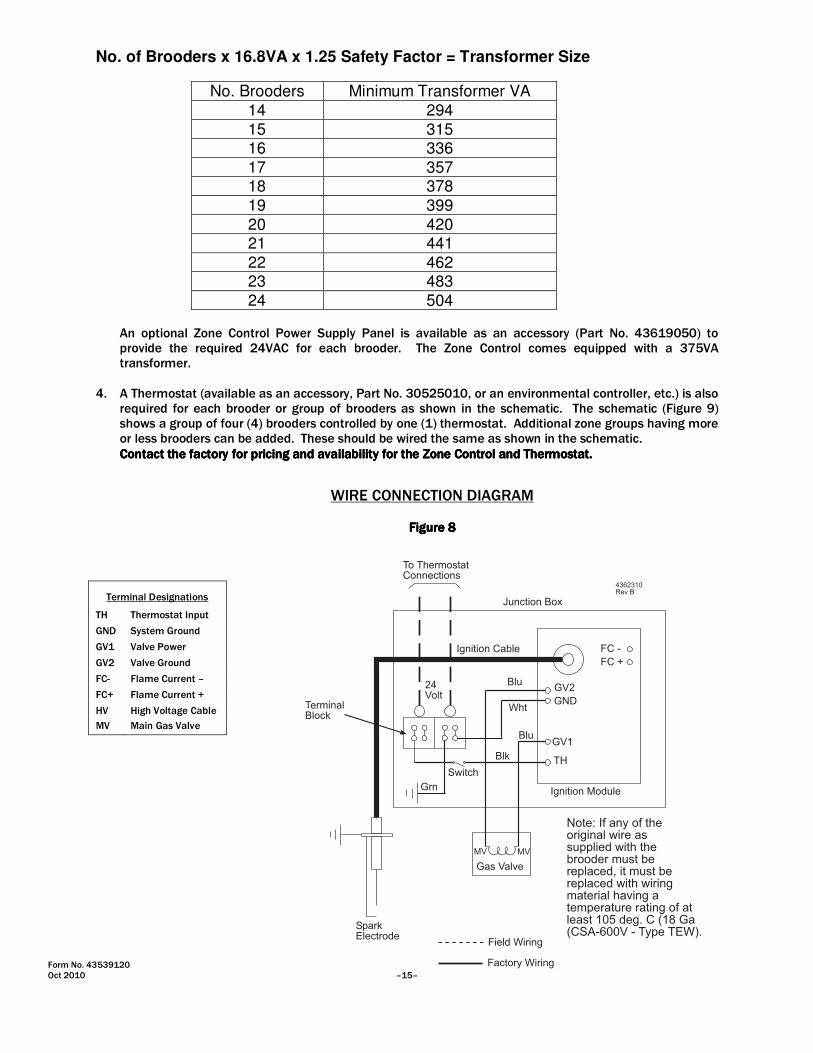
No. of Brooders x 16.8VA x 1.25 Safety Factor = Transformer Size
No. Brooders Minimum Transformer VA
14 294
15 315 16 336
17 357 18 378
19 399
20 420 21 441
22 462 23 483
24 504 An optional Zone Control Power Supply Panel is available as an accessory (Part No. 43619050) to
provide the required 24VAC for each brooder. The Zone Control comes equipped with a 375VA transformer.
4. A Thermostat (available as an accessory, Part No. 30525010, or an environmental controller, etc.) is also
required for each brooder or group of brooders as shown in the schematic. The schematic (Figure 9) shows a group of four (4) brooders controlled by one (1) thermostat. Additional zone groups having more or less brooders can be added. These should be wired the same as shown in the schematic.
Contact the factory for pricing and availability for the Zone Control and Thermostat.Contact the factory for pricing and availability for the Zone Control and Thermostat.Contact the factory for pricing and availability for the Zone Control and Thermostat.Contact the factory for pricing and availability for the Zone Control and Thermostat.
Terminal Designations
TH Thermostat Input
GND System Ground
GV1 Valve Power
GV2 Valve Ground
FC- Flame Current –
FC+ Flame Current +
HV High Voltage Cable
MV
Main Gas Valve
WIRE CONNECTION DIAGRAM
FigurFigurFigurFigure 8e 8e 8e 8
To ThermostatConnections
Junction Box
TerminalBlock
Ignition Cable
Blu
Wht
Blu
Blk
24Volt
Grn
Switch
SparkElectrode
Field Wiring
Factory Wiring
Gas Valve
MV MV
Ignition Module
FC -
FC +
GV2
GND
GV1
TH
Note: If any of theoriginal wire assupplied with thebrooder must bereplaced, it must bereplaced with wiringmaterial having atemperature rating of atleast 105 deg. C (18 Ga(CSA-600V - Type TEW).
4362310Rev B

Form No. 43539120 –16– Oct 2010
SCHEMATIC Figure 9Figure 9Figure 9Figure 9
To
Additional
Zones
To Zone
Control Box
WHT 14 to 12Ga.
BLK 14 to 12Ga.Main Feeder Line
WHT
BLK
Zone Feeder Line
ThermostatDSI Electrical Boxat Brooder
BLK
14G
a.
BLK
14G
a.
BLK
18G
a.
WH
T 1
8G
a.
Bro
oder
Bra
nch C
ircuit
24Volt
24Volt
This schematic represents a group of four (4) brooders controlledby one (1) thermostat. Additional zones should be wired as shown.
Note: Onethermostat shouldbe used to controleach individualzone group.
Figure 8aFigure 8aFigure 8aFigure 8a
The cable gland used for field connectionsof the power supply wiring MUST betightened to prevent water from enteringthe box and causing condensation to formwhich may result in ignition failure.
Avoid Equipment Failure.
Cable Gland
Ignition Control Assembly
Form No. 43539120 Oct 2010 –17–
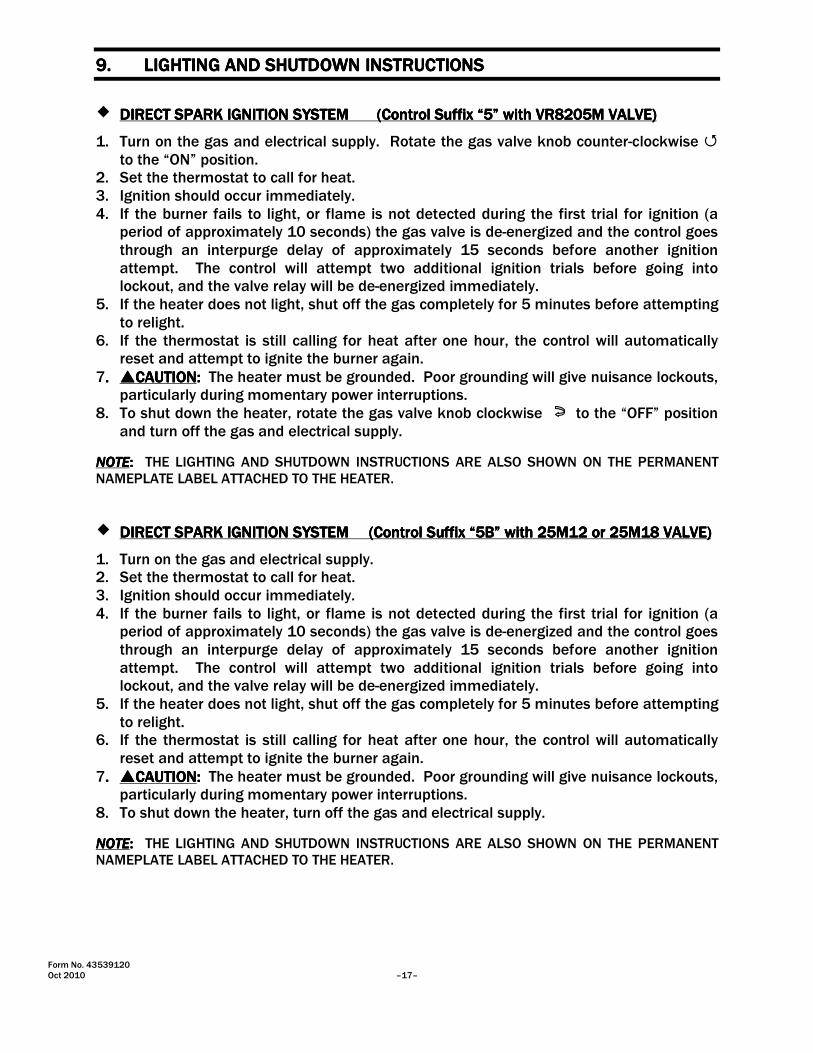
9.9.9.9. LIGHTING AND SHUTDOWN INSTRUCTIONSLIGHTING AND SHUTDOWN INSTRUCTIONSLIGHTING AND SHUTDOWN INSTRUCTIONSLIGHTING AND SHUTDOWN INSTRUCTIONS
� DIRECT SPDIRECT SPDIRECT SPDIRECT SPARK IGNITION SYSTEMARK IGNITION SYSTEMARK IGNITION SYSTEMARK IGNITION SYSTEM (Control(Control(Control(Control Suffix “5”Suffix “5”Suffix “5”Suffix “5” with VR8205M VALVEwith VR8205M VALVEwith VR8205M VALVEwith VR8205M VALVE)))) 1. Turn on the gas and electrical supply. Rotate the gas valve knob counter-clockwise �
to the “ON” position. 2. Set the thermostat to call for heat. 3. Ignition should occur immediately. 4. If the burner fails to light, or flame is not detected during the first trial for ignition (a
period of approximately 10 seconds) the gas valve is de-energized and the control goes through an interpurge delay of approximately 15 seconds before another ignition attempt. The control will attempt two additional ignition trials before going into lockout, and the valve relay will be de-energized immediately.
5. If the heater does not light, shut off the gas completely for 5 minutes before attempting to relight.
6. If the thermostat is still calling for heat after one hour, the control will automatically reset and attempt to ignite the burner again.
7.... ����CAUTIONCAUTIONCAUTIONCAUTION:::: The heater must be grounded. Poor grounding will give nuisance lockouts, particularly during momentary power interruptions.
8. To shut down the heater, rotate the gas valve knob clockwise to the “OFF” position and turn off the gas and electrical supply.
NOTENOTENOTENOTE: : : : THE LIGHTING AND SHUTDOWN INSTRUCTIONS ARE ALSO SHOWN ON THE PERMANENT NAMEPLATE LABEL ATTACHED TO THE HEATER.
� DIRECT SPDIRECT SPDIRECT SPDIRECT SPARK IGNITION SYSTEM ARK IGNITION SYSTEM ARK IGNITION SYSTEM ARK IGNITION SYSTEM (Control(Control(Control(Control SuSuSuSuffix “5B”ffix “5B”ffix “5B”ffix “5B” with 25M12with 25M12with 25M12with 25M12 or 25M18or 25M18or 25M18or 25M18 VALVEVALVEVALVEVALVE)))) 1. Turn on the gas and electrical supply. 2. Set the thermostat to call for heat. 3. Ignition should occur immediately. 4. If the burner fails to light, or flame is not detected during the first trial for ignition (a
period of approximately 10 seconds) the gas valve is de-energized and the control goes through an interpurge delay of approximately 15 seconds before another ignition attempt. The control will attempt two additional ignition trials before going into lockout, and the valve relay will be de-energized immediately.
5. If the heater does not light, shut off the gas completely for 5 minutes before attempting to relight.
6. If the thermostat is still calling for heat after one hour, the control will automatically reset and attempt to ignite the burner again.
7.... ����CAUTIONCAUTIONCAUTIONCAUTION:::: The heater must be grounded. Poor grounding will give nuisance lockouts, particularly during momentary power interruptions.
8. To shut down the heater, turn off the gas and electrical supply.
NOTENOTENOTENOTE: : : : THE LIGHTING AND SHUTDOWN INSTRUCTIONS ARE ALSO SHOWN ON THE PERMANENT NAMEPLATE LABEL ATTACHED TO THE HEATER.

Form No. 43539120 –18– Oct 2010
10.10.10.10. VENTILATIONVENTILATIONVENTILATIONVENTILATION
Minimum ventilation required is 160 CFM per brooder. Lower ventilation ratesmay result in poor gas/air mixture causing high carbon monoxide levels anddistortion to the emitter assembly.
Failure to follow these guide lines may result in death, serious injury, propertydamage or illness from Carbon Monoxide poisoning.
FOR YOUR SAFETY: FOR YOUR SAFETY: FOR YOUR SAFETY: FOR YOUR SAFETY: Exhaust fans must be operating on an appropriate cycle when heating the building to avoid high concentrations of carbon monoxide and water vapor.
The temptation, particularly during the winter months, is to close up the poultry house to conserve heat and save money. This must be resisted, particularly during the heating up period prior to the arrival of the stock, because the lack of ventilation can restrict the required amount of combustion air for the brooders causing them to burn improperly and produce levels of carbon monoxide which could be harmful to people and the stock.
�WARNINGWARNINGWARNINGWARNING: : : : Carbon Monoxide is an odorless and poisonous gas. Extended exposure to carbon monoxide
may lead to death.... Early signs of carbon monoxide poisoning resemble the flu, including headaches, dizziness and/or nausea. If you experience these signs, GET FRESH AIR IMMEDIATELY. Have the brooders serviced as soon as possible and check the ventilation in the house.
The National Fuel Gas Code requires a minimum of 4 CFM per 1000 Btu/hr of brooder input for ventilation. This requirement means that a total of 160 CFM is required per brooder. Ventilation requirements may vary depending on other equipment that may be located in the building requiring ventilation. All ventilation requirements should be addressed before sizing the necessary gravity or mechanical means to accomplish this ventilation.
While ventilation is necessary for proper brooder operation and proper growing conditions for the stock, excessive ventilation can result in high fuel consumption. Adjust the ventilation as necessary for optimum performance of the brooders and growing conditions for the stock.
11.11.11.11. CLEANING AND ANNUAL CLEANING AND ANNUAL CLEANING AND ANNUAL CLEANING AND ANNUAL MAINTENANCEMAINTENANCEMAINTENANCEMAINTENANCE
ELECTRIC SHOCK & EXPLOSION HAZARD
Disconnect electrical power and gas supply beforeservicing.
Failure to do so may result in death or serious injury.
To keep your brooder in good operating condition, we recommend that after each crop you blow To keep your brooder in good operating condition, we recommend that after each crop you blow To keep your brooder in good operating condition, we recommend that after each crop you blow To keep your brooder in good operating condition, we recommend that after each crop you blow any dust and dirt from the brooder with compressed air.any dust and dirt from the brooder with compressed air.any dust and dirt from the brooder with compressed air.any dust and dirt from the brooder with compressed air. If at anytime you notice a lazy yellow flame as shown below then the brooder needs to be cleaned:
CAUTION: TURN THE GAS AND ELECTRIC (IF EQUIPPED) SUPPLIES OFF AND ALLOW THE BROODER TO COOL DOWN BEFORE ATTEMPTING ANY MAINTENANCE.

Form No. 43539120 Oct 2010 –19–
GOOD(hard blue flame)
BAD(lazy yellow flame)
Yellow streaks in the tip ofthe flame is normal. Thisis dust in the atmosphere
burning in the flame.
Inspect the flame characteristics by running the brooder with the Mechanical Ventilation OFF and
Natural Ventilation by opening the doors at the end of the house. This will result in a flame that is more stable to observe.
If at anytime 25% or more of the flame turns yellow or on an annual basis, we recommend that the burner and orifices be disassembled and cleaned. Built up deposits in the burner will not be effectively cleaned with compressed air.
Turn SwivelClamp1
2
Apply LP andNatural GasApprovedThread Sealant
3
RemoveMain BurnerOrifice
1. Release the main burner orifice fitting and pan from the burner by turning the swivel clamp. CAUTION: In order to prevent damage to the control arm tubing, first place your hand under the pan and allow the control to lower gently under its own weight.
2. Unscrew the main burner orifice from the orifice fitting and clean the orifice hole with a drill bit the same size as the orifice or by soaking the orifice in acetone liquid cleaner. Dry the orifice by blowing compressed air through it. NOTE: Care must be taken not to ream the orifice hole to a larger diameter as this will result in over firing the burner and potentially causing damage to the emitter.
3. Apply pipe thread sealant Part No. 05001010 PIPETITE-STIK #11175 (resistant to LP Gas) to the threads
of the orifice and replace it into the orifice fitting. Avoid over tightening the orifice as this will make future removal very difficult.
4. Before removing the burner base it is advisable to make sure you have spare screws and nuts available
Part No. 02281010 M5 x 35MM SET SCREW-HHD SS and Part No. 02282010 M5 HEX NUT SS. The screws and nuts used to secure the burner are stainless steel and may gall and therefore shear off during disassembly.

Form No. 43539120 –20– Oct 2010
5. Remove the main burner. Clean around the burner cap ports and upper burner surfaces with a small
bristle brush (available as an accessory, Part No. 43295010) or other small wire brush. After cleaning the burner ports, use the same brush to clean inside the burner base and venture. Compressed air can be blown onto the burner ports and through the burner venturi to remove any remaining dust.
6. Clean both the inside and outside surfaces of the perforated emitter assembly with a large bristle brush (available as an accessory, Part No. 43295020) or other large bristle type brush; then use compressed air to remove any burnt dust or dirt particles from the emitter.
7. Blow all dirt and dust off the canopy with compressed air. 8. Care should be taken when reassembling the burner base to avoid distorting the burner by over
tightening the securing nuts. If any screws sheared during the removal process they must be replaced with stainless screws, the screw head is accessible by removing the emitter assembly, see the diagram below.
Do not over tighten this willpotentially distort the burnerand disrupt the flame pattern.
If the screw shears it is necessaryto remove the emitter for accessto the screw. Unscrew throughthe cap from inside the emitter.
5
Wire Brush - Short(Part #43295010) 6

Form No. 43539120 Oct 2010 –21–
12.12.12.12. TROUBLESHOOTINGTROUBLESHOOTINGTROUBLESHOOTINGTROUBLESHOOTING
A)A)A)A) IGNITION MODULE DIAGNOSTICS
The LED located on the ignition module (see Figure 10) will flash ON for ¼ second, then OFF for ¼ second during a fault condition. The pause between fault codes is 3 seconds.
LED Indication Error Mode
Steady On Internal Control Failure
2 Flashes Flame Sense Fault 3 Flashes Ignition Lockout
B)B)B)B) FLAME SENSOR TESTING
The flame current is the current that passes through the flame from the sensor to the ground. The minimum flame current necessary to keep the system from lockout is 0.7 microamps. To measure the flame current, connect an analog DC microammeter to the FC- and FC+ terminals per diagram. The meter should read 0.7 µA or higher when the burner is running full on. If the meter reads below zero, the meter leads are reversed. Disconnect power and reconnect the meter leads for proper polarity.
C)C)C)C) SPARK ELECTRODE INSPECTION
1. Inspect the spark electrode for possible cracks in the ceramic insulator. Replace if necessary.
2. Check for proper electrode spark gap. This should measure 1/8”. Re-bend to correct gap or replace electrode if necessary.
3. Check that the electrode ground rod is located to center of the burner port as shown in illustration. If electrode is misaligned, loosen the screws and nuts holding the electrode and reposition to correct location. Re-tighten screws and nuts.
Figure 13Figure 13Figure 13Figure 13
Ground rod locatedto center of thisport.
Ground rod mis-alignedwith this port.
Spark gap 1/8�
Correct ElectrodeLocation
In-correct ElectrodeLocation
Form No. 43539120 –22– Oct 2010
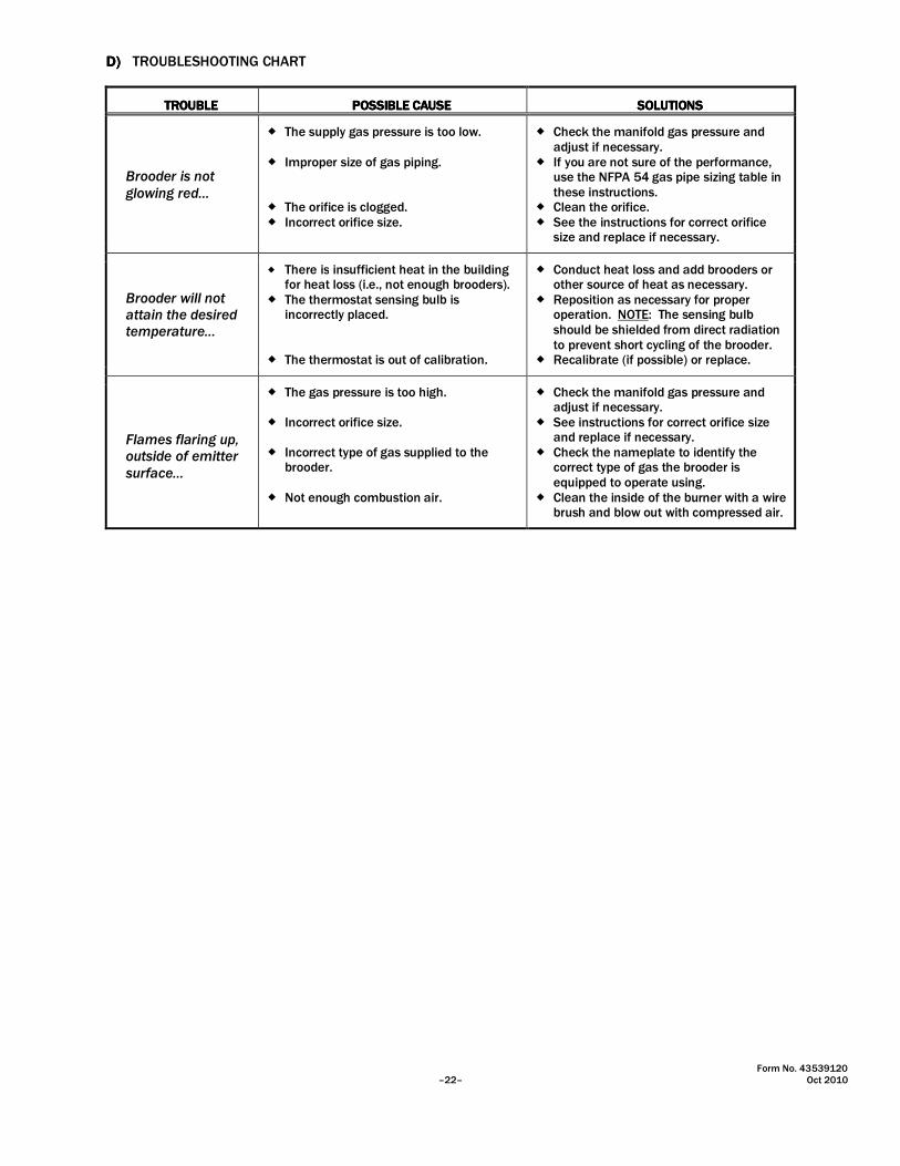
DDDD)))) TROUBLESHOOTING CHART
TROTROTROTROUBLEUBLEUBLEUBLE POSSIBLE CAUSEPOSSIBLE CAUSEPOSSIBLE CAUSEPOSSIBLE CAUSE SOLUTIONSSOLUTIONSSOLUTIONSSOLUTIONS
Brooder is not glowing red…
� The supply gas pressure is too low. � Improper size of gas piping. � The orifice is clogged. � Incorrect orifice size.
� Check the manifold gas pressure and adjust if necessary.
� If you are not sure of the performance, use the NFPA 54 gas pipe sizing table in these instructions.
� Clean the orifice. � See the instructions for correct orifice
size and replace if necessary.
Brooder will not attain the desired temperature…
� There is insufficient heat in the building for heat loss (i.e., not enough brooders).
� The thermostat sensing bulb is incorrectly placed.
� The thermostat is out of calibration.
� Conduct heat loss and add brooders or other source of heat as necessary.
� Reposition as necessary for proper operation. NOTE: The sensing bulb should be shielded from direct radiation to prevent short cycling of the brooder.
� Recalibrate (if possible) or replace.
Flames flaring up, outside of emitter surface…
� The gas pressure is too high. � Incorrect orifice size. � Incorrect type of gas supplied to the
brooder. � Not enough combustion air.
� Check the manifold gas pressure and adjust if necessary.
� See instructions for correct orifice size and replace if necessary.
� Check the nameplate to identify the correct type of gas the brooder is equipped to operate using.
� Clean the inside of the burner with a wire brush and blow out with compressed air.

Form No. 43539120 Oct 2010 –23–
DDDD)))) TROUBLESHOOTING CHART (Continued)
Is there 115V into thetransformer?
Is there 24V at theterminal block on thebrooder. See wirediagram on page 15.
NO
YESTurn up thermostatto call for heat. Doesthe electrode spark?
YES
NO YES
NO
Check the spark gapis it 1/8�?
NO
YES
YES
NO
YES
NO
YES
NO
YES
NO
YES
NOYES
NO
YES
NO
YES
NO
Is there 24V out fromthe transformer?(Zone control)
NO
YES
Does the modulehave a steady redLED?
Replace ignitionmodule. PN30632030
YES
NO
YES
NO
Swap out theelectrodes from aworking brooder,does it spark?
Replace electrodeassembly. PN30216060
Check ignition cablefor continuity.Replace if necessaryPN 30634432
Check building wiringand repair asnecessary.
Check building wiringand circuit breakers.Repair as necessary.
Refer to brooderzone controlinstructions fortroubleshooting.
Does the burnerlight? (Note: thereare 3 tries for ignitionbefore lockout)
Check the gas valveis it turned on.
Turn on the gasvalve.
Does the modulehave a steady redLED?
Replace ignitionmodule. PN30632030
Check the gas lines,are all the shut off�sin the on position andhave the lines beenpurged of air?
Turn on the shut off�sand purge thepipework of air.
Is there 24V at thegas valve?
Replace gas valvePN�s 30333100 NG,30333110 LP.
Check control wiringand reconnectterminals.
Does the burner stay lit?
Check the orifice is itblocked.
YES
NO
Clean out orifice
Check the flamecurrent to the modulesee section 12. Is thecurrent less than0.7µA?
Does the modulehave a steady redLED?
Replace ignitionmodule. PN30632030
Contact Dealer forfurther assistance.
Burner operationtrouble shoot ends
YES
NO
Swap out theelectrodes from aworking brooder,does it stay lit?
Replace electrodeassembly. PN30216060
Check ignition cabledoes it havecontinuity?
YES
NO
Replace ignitioncable PN 30634432
YES
NOCheck the orifice is itblocked.
Clean out orifice
Check the inlet gaspressure is higher thanthe minimum requiredand adjust the outletgas pressure persection 7a.
YES
NO
Check the gas valveoutlet pressure, seesection 7a. Is the gaspressure correct?
Contact Dealer forfurther assistance.
YES
Check that electrodeground rod is locatedin center of theburner port persection 12C.
Adjust spark gap andcheck that electrodeground rod is locatedin center of theburner port persection 12C.Retry ignition.

Form No. 43539120 –24– Oct 2010
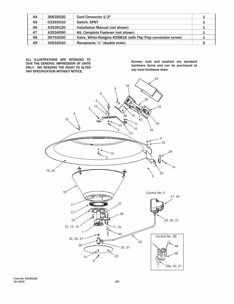
13.13.13.13. REPLACEMENT PARTS GUIDEREPLACEMENT PARTS GUIDEREPLACEMENT PARTS GUIDEREPLACEMENT PARTS GUIDE
Item No. Part No. Description SRB40EZ-5
Qty
1 02166010 #8-32 x 3/8" Pan Head Screw 2
1a 02167040 #8-32 Hex Locknut - Keps 4
1b 02195010 #8 x 1/2" Sheet Metal Screw 2
2 02127230 #12-24 Hex Nut 1
3 02320010 #12-24 x 1/2" Hex Head Screw 1
4 02167010 1/4-20 Hex Locknut - Keps 7
5 02259010 1/4-20 x 5/8" Hex Head Screw 2
6 02309000 1/4-20 x 2" Eyebolt (includes one nut) 1 7 02168050 #10-24 x 3/8” Pan Head Screw 2
8 02189020 #10 x 1/2" Sheet Metal Screw 2
9 02004010 #10-32 x 1/4" Pan Head Screw 1
10 02305010 #M8 Flat Washer 8
11 02281010 #M5 x 35mm Hex Head Screw 3
12 02282010 #M5 Hex Nut 3
13 02301010 #M5 Flat Washer 3
14 02302010 #M5 Spring Lockwasher 4
15 30257000 Wire Tie (not shown) 3
16 43525150 Emitter Assembly (less burner cap) 1
17 43309000 Burner Cap 1
18 43633030 Burner Base Assembly (with swivel clamp) 1
19 43303000 Reflector Canopy - Aluminum 1
20 43303010 Reflector Canopy - Galvanized 1
21 43826010 Low Profile Hanging Bracket 1
22 43304030 Burner Pan (center mounted) 1
23 43983020 Manifold Support Assembly (radiation shield) 1
24 43982020 V-Clamp (manifold support) 1
25 03259840 Main Burner Orifice (1.9mm) - LP Gas 1
26 03259330 Main Burner Orifice (#33) - Natural Gas 1
27 03259500 Main Burner Orifice (#50) - LP/Butane Gas 1
28 43305990 Main Burner Orifice Fitting Sub-Assembly 1
29 30397000 1/2 MPT x 3/8 Tube Fitting (USA Style) 1
29a 03602070 3/8 MPT x 3/8 Tube Fitting (USA Style) 1
30 03600020 3/8" Compression Sleeve (USA Style) 2
31 03601020 3/8" Compression Nut (USA Style) 2
32 43307160 Main Burner Tubing, 3/8" 1
33 43978010 Junction Box Sub-Assembly 1
34 43977030 Junction Box Lid 1
35 43977040 Bracket, Module Stand-Off 1
36 43536140 Bracket, Box Support 1
37 43637100 Bracket, Electrode Holder 1
38 30216060 Spark Electrode Fenwal #22-1000011-369 1
39 30632030 Ignition Module Fenwal #35-605950-015 1
40 30634432 Ignition Cable - 35" #PSE-GF27 1
41 30333100 Valve, Honeywell #VR8205M-2963 Nat. Gas 1
42 30333110 Valve, Honeywell #VR8205M-2971 LP Gas 1
43 30281000 Terminal Block #EK-204 1
Form No. 43539120 Oct 2010 –25–
44 30635020 Cord Connector 1/2" 1
45 03393010 Switch, SPST 1
46 43539120 Installation Manual (not shown) 1
47 43534090 Kit, Complete Fastener (not shown) 1
48 30753000 Valve, White-Rodgers #25M18 (with Flip/Flop conversion screw) 1
49 30516010 Receptacle, ¼” (double male) 2
4
10
2
4
10
6
835
34
39
33
44
45
43
1b
4
10
21
10
4
4
10
24
1a
235
10
3
19, 20
16
11
17
18
12, 13, 14
7
25, 26, 27
28
9
22
30, 31
32
40
1, 1a
38
37
29, 30, 31
41, 42
14
36
Control No. 5
1234
29a, 30, 31
48
Control No. 5B
49
ALL ILLUSTRATIONS ARE INTENDED TO GIVE THE GENERAL IMPRESSION OF UNITS ONLY. WE RESERVE THE RIGHT TO ALTER ANY SPECIFICATION WITHOUT NOTICE.
Screws, nuts and washers are standard hardware items and can be purchased at
any local hardware store.

Form No. 43539120 –26– Oct 2010
GAS-FIRED PRODUCTS LIMITED WARRANTY
LIMITED WARRANTY Gas-Fired Products, Inc. (GFP), the manufacturer, warrants the original owner of any Space-Ray Poultry Heating Product that it will be free from defects in material or workmanship under normal use and service. The heater(s) shall be installed, used and maintained strictly in accordance with the manufacturer's instructions. The manufacturer's sole obligation under this warranty is limited to furnishing replacement parts, F.O.B. Charlotte, NC, for 12 months from the date of installation, or 18 months from the date of shipment by the manufacturer, whichever period expires first. Labor charges for the removal of defective parts or the installation of replacement parts are not included. ADDITIONAL WARRANTY ON MODEL SRB40 BROODER EMITTER AND MODEL CTA TUBE HEATER HEAT EXCHANGER: Additionally, the manufacturer will at any time during a 36 month period after installation or 42 months from the date of shipment by the manufacturer, whichever period expires first, furnish at no cost to the original owner, replacement emitter assemblies or heat exchanger tubes which have become inoperative by reason of any defect in our workmanship, materials or construction. The manufacturer will not be responsible for labor charges incurred for removal or installation of emitters. Any transportation charges involved in the return or repair are excluded. WARNING: Manufacturer's warranty shall not apply: (a) to circumstances where gas pressure to each heater is higher than that specified for each heater; (b) to circumstances where the type of gas is different than the type of gas noted on the name plate for each heater; (c) to water damage to gas controls; and (d) to any heater or component which has been repaired or replaced with other than factory parts, modified in any way, misused or damaged, or which has been used contrary to the manufacturer's written instructions. LIMITATION OF WARRANTY: THERE ARE NO WARRANTIES, EXPRESS OR IMPLIED, WHICH EXTEND BEYOND THE DESCRIPTION ON THE FACE HEREOF. WITHOUT LIMITING THE FOREGOING, THE MANUFACTURER EXPRESSLY EXCLUDES ANY AND ALL IMPLIED WARRANTIES, INCLUDING BUT NOT LIMITED TO ANY IMPLIED WARRANTY OF FITNESS FOR A PARTICULAR PURPOSE AND ANY IMPLIED WARRANTY OF MERCHANTABILITY FOR ITS PRODUCTS. If any provision of this warranty is found to be void, unenforceable or unconscionable, then that portion is hereby severed and the remainder of this warranty is hereby saved and shall remain in force. EXCLUSIVE REMEDY: The sole and exclusive remedy under this warranty is the replacement of the defective parts or brooders as hereinabove specified. THE MANUFACTURER DOES HEREBY EXPRESSLY EXCLUDE ANY AND ALL LIABILITY FOR INCIDENTAL OR CONSEQUENTIAL DAMAGES UNDER THIS OR ANY OTHER WARRANTY. Without intending to limit the aforesaid exclusion, THE MANUFACTURER DOES HEREBY EXCLUDE ANY LIABILITY UNDER THIS OR ANY OTHER WARRANTY FOR INJURIES OR COMMERCIAL LOSSES TO PROPERTY THAT RESULT FROM THE OPERATION, PROPER OR IMPROPER, OF ITS PRODUCTS. ADDITIONAL TERMS: Manufacturer assumes no liability for delay in performing its obligations under this warranty. Manufacturer assumes no liability for failure in performing its obligations there under if failure results directly or indirectly from any cause beyond its control, including but not limited to acts of God, acts of Government, floods, fires, shortages of materials, strikes and other labor difficulties or delays or failures of transportation facilities. This is a Non-Residential product. Installation and service shall be by a Licensed Contractor and in accordance with National and Local Codes.

Form No. 43539120 Oct 2010 –27–
When presenting warranty claims, proof of date of purchase must be submitted.
No Representative is authorized to assume for the manufacturer, any liability except as set forth above.
For the name of your nearest distributor in case of claim under this warranty, contact: Space-Ray Poultry Heating Products / Gas-Fired Products, Inc. / 305 Doggett St., P.O. Box 36485 / Charlotte, NC 28236 / Phone: (704) 372-3488 / Fax: (704) 332-5843 / email: [email protected].
FOR YOUR RECORDS:
Space-Ray Brooder Model Number: Date Installed:
Serial Numbers:
For replacement parts, please contact your local distributor or:
SPACE-RAY 305 Doggett Street � Charlotte, NC 28203-4923
Phone (704) 372-3488 � Fax (704) 332-5843 � [email protected]
B