radial piston air motors - ferguson … # 1 of 12 form no. 1000403 created date: 13 mar 2009 radial...
TRANSCRIPT
Page # 1 of 12 Form No. 1000403 Created Date: 13 Mar 2009
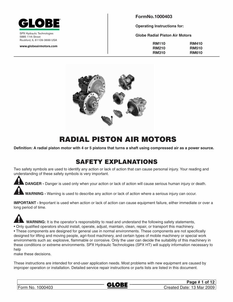
RADIAL PISTON AIR MOTORSDefinition: A radial piston motor with 4 or 5 pistons that turns a shaft using compressed air as a power source.
SAfeTy exPLANATIONSTwo safety symbols are used to identify any action or lack of action that can cause personal injury. Your reading and understanding of these safety symbols is very important.
DANGER - Danger is used only when your action or lack of action will cause serious human injury or death.
WARNING - Warning is used to describe any action or lack of action where a serious injury can occur.
IMPORTANT - Important is used when action or lack of action can cause equipment failure, either immediate or over a long period of time.
WARNING: It is the operator’s responsibility to read and understand the following safety statements,• Only qualified operators should install, operate, adjust, maintain, clean, repair, or transport this machinery.• These components are designed for general use in normal environments. These components are not specifically designed for lifting and moving people, agri-food machinery, and certain types of mobile machinery or special work environments such as: explosive, flammable or corrosive. Only the user can decide the suitability of this machinery in these conditions or extreme environments. SPX Hydraulic Technologies (SPX HT) will supply information necessary to help make these decisions.
These instructions are intended for end-user application needs. Most problems with new equipment are caused by improper operation or installation. Detailed service repair instructions or parts lists are listed in this document.
FormÊNo.Ê1000403
Operating Instructions for:
Globe Radial Piston Air Motors
RM110RM210RM310
RM410RM510RM610

Page # 2 of 12 Created Date: 13 Mar 2009 Form No. 1000403
SAfeTy PRecAuTIONS
WARNING GENERAL OPERATION• All WARNING statements must be carefully observed to help prevent personal injury.• Before operating the motor, all air connections must be tightened with the proper tools. Do not overtighten. Consult
manufacturer of parts (fitting, hoses, etc.) for proper installation instructions. Connections should only be tightened securely and leak-free. Overtightening can cause premature thread failure or high pressure fittings to split at pressures lower than their rated capacities.
• Should an air hose ever rupture, burst, or need to be disconnected, immediately shut off the air supply and release all pressure. Never attempt to grasp a leaking pressurized hose with your hands. The force of escaping air could cause serious injury.
• Do not subject the air lines to potential hazard such as fire, sharp surfaces, extreme heat or cold, or heavy impact. Do not allow the air line to be altered or kink, twist, curl, crush, cut, or bend so tightly that the air flow within the hose is blocked or reduced. Periodically inspect the air line for wear, because any of these conditions can damage the line and possibly result in personal injury.
• Do not use the air line to move attached equipment. Stress can damage air lines and possibly cause personal injury.• Air line material and coupler seals must be compatible with the motor used. Air lines also must not come in contact with
corrosive materials such as creosote-impregnated objects and some paints. Consult the manufacturer before painting a line. Air line deterioration due to corrosive materials can result in personal injury. Never paint the couplers.
• Inspect machine for wear, damage, and correct function before each use. Do not use machinery that is not in proper working order, but repair or replace it as necessary.
• Modification of a product requires written SPX authorization.• Use only components with the same pressure rating when assembling a system or machine.
Motor• Do not exceed the air pressure rating noted on the motor data plate. Creating pressure beyond the rated pressure can
result in personal injury.
Recommended LubricantsFor operation at normal ambient temperature 33 to 90° F (0 to 32° C) Crankcase Airline Crankcase Air line
Shell Tellus 100 Tellus 37 Regent Regal PE.RO Rando ‘A’
B.P. Energol HL175 Energol HLP65 Castrol Hyspin 175 Hyspin 70
Esso Nuto H.64 Fanox 38 Mobil D.T.E. Extra Almo Oil Heavy Heavy No. 1
For extremes of ambient temperatures consult the manufacturers
Approximate Capacity
Horizontal Vertical ml in3 ml in3
RM110 75 ml 4.5 150 ml 9.1 RM210 300 ml 20.1 450 ml 27.5 RM310 350 ml 21.3 600 ml 36.6 RM410 500 ml 30.5 940 ml 57.3 RM510 1.1 L 67 2.1 L 128 RM610 1.1 L 67 2.1 L 128

Page # 3 of 12 Form No. 1000403 Created Date: 13 Mar 2009
WARNING: For operation in extreme ambient temperatures, consult SPX HT.
MAINTeNANce
Air SupplyThe air filter should be drained regularly and examined for clogging of the element.The air line lubricator should be replenished as required and set to give
3-4 drops per minute RM1104-5 drops per minute RM2105-6 drops per minute RM3106-8 drops per minute RM4106-8 drops per minute RM5108-10 drops per minute RM610
Double the above drip rate if intermittent operation.
INSTALLATION & SeT-uPNote: Numbers in parenthesis refer to exploded view drawing on page 8.
Mounting PositionsThe motor is normally mounted in a horizontal position with the filler/breather plug towards the top (Fig. 1). It may also be mounted with the shaft vertically downwards (Fig. 2)/ As supplied the motors have been run up and tested using protective oil and then drained for transit. It is vital that each motor is mounted in the correct orientation (vertically or horizontally) and re-filled to the correct oil level as shown below. The RM110 — RM310 motors have a dipstick for vertical mounting (fig. 2) and the lower mark on this dipstick provides the oil level. Oil levels are achieved on motors in the horizontal position by filling to the plugs marked part 60 fitted in housing 3 (RM110 to RM410) and plug (26) fitted to the top face of engine case (27) (RM510 and RM610). The RM410, RM510 and RM610 motors have a combined horizontal drain and vertical level plug (add oil until this level has been reached) (26).To fill motors with oil remove the combined breather and oil filler plug (46). Ensure breather plug is in the vertical position. It may be necessary to fit an elbow between the breather plug and the motor (see Fig. 2).
Note: Damage by lack of lubrication will occur if motors are mounted shaft up or at an anglePlease consult SPX HT for other mounting options.
Note: When first running the motor some light oil should be injected into the inlet connection to ensure adequate lubrication until the airline lubrication is established.
Shaft rotation as shown with inlet at ‘A’. Reverse rotation is obtained with inlet at ‘B’.
Horizontal Vertical

Page # 4 of 12 Created Date: 13 Mar 2009 Form No. 1000403
WARNING: If improperly used, pressurized equipment can be potentially hazardous. Therefore:• Air line connections must be securely fastened before building pressure in the system.• Release all system pressure before loosening any air line connections in the system.
Air InletThe motor is normally supplied with the inlet/exhaust adaptor plate (72). All motors are reversible.
Air SupplyMaximum Working Pressure 8 bar-120 psi.The air supply must be clean and free from moisture. An air line filter and mist lubricator should be incorporated in the air supply line, located immediately before the motor. If the rated performance of the motor is to be obtained, all valves and pipework must be of adequate size Note: Consult factory for diameter sizes, however never use pipe’s diameter smaller than the motor’s port diameter. Valves should be sited as close as possible to the motor. For short pipe runs, e.g. up to 2 metres, the supply line should be the same size as the motor ports and larger for longer runs. The exhaust flow must be free of any restrictions; this is critical for the motor’s operation.
INSTALLATIONMount motor in operating position. Check oil level. Before connecting to the air supply blow out air lines to remove any loose scale, swarf or abrasive dust which may be present. Remove and dispose the red plastic dust-caps and the ‘O’ ring seal (45).
For unidirectional operation check the required direction of rotation and connect the air supply line to the appropriate port on the inlet/exhaust adaptor plate (72) leaving the other port open or pipe downwards if exposed to the atmosphere.The motor should not be allowed to race. Always operate within the catalogue speed curves.
WARNING: When first running the motor, some light oil should be injected into the inlet connection to ensure adequate lubrication until the air line lubrication is established.
Maintenance Lack of maintenance will shorten the life of the motor and could cause failure.
MotorThe oil level in the motor casing must be maintained. The frequency of replenishment will depend upon the application and usage. The motor case should be drained and refilled after 25 hours of initial running and every 200 hours thereafter or sooner if found necessary e.g. (contamination of oil by water from the air line.)
SeRvIcINg
Disassembly Procedure• Remove the motor from its operating position to a clean working surface ready for stripping. Prepare the motor for
opening by externally cleaning the motor.• Drain the oil from the motor casing by removing the drain plug (26).• Disassembly and re-assembly will be simplified if the crankshaft (20 A/B) or output shaft (67) RM510 and RM610 is held
vertically in a soft-jawed vice or supported on suitable packing to raise the shaft clear of the working surface.
Page # 5 of 12 Form No. 1000403 Created Date: 13 Mar 2009
Removal of Rotary Valve Housing Assembly• Remove inlet/exhaust adaptor plate (72) or control valve (if fitted).• Remove valve cover (51).• Release bolts (38) and Rotary valve housing assembly (3) can be eased upward.• On RM110 to 410 motors remove grub screw (49) together with the valve side balance weight (number 35).• All motors — carefully remove rotary valve (2) from the housing (3). This is generally done from the inside outwards
and inspect both the rotary valve and the housing for wear. The normal clearance at manufacture between these two components is .002-.003” (.05-.075). Excessive wear will cause air leakages and loss of efficiency of the unit.
Motors - RM110, RM210, RM310, RM410These units are of the king rod variety and again it is wise to slightly rotate the crankshaft (part no. 20A/B) in either direction to test any excessive wear on either the king rod bearing or the pivot pins (part no. 29). Having first removed the outer spacing washer (31/34) withdraw pivot pins (part no. 29). This procedure is usually done with a bent rod withdrawing the pins from the inside outwards. Remove all cylinder cap bolts (part 37) and by pushing the queen rods (part 30) outwards the entire piston and rod assembly can be removed from the motor. Turn the motor unit over to extract the crank bearing or bearings (part no. 48). The main king rod (part no. 12) can then be lifted upwards and tilted over the top of the crankshaft. Remove the main king rod, piston and cylinder from the motor. Remove the output shaft circlip (14), spacer (15) and shims (16). Remove the countersunk bolts (52) holding the output flange (24A/B) on to the engine case (part no. 27) can be removed.Drift the crankshaft inwards from the flange plate (24A). To remove the outer shaft bearings (55 and 56) drift to their to their respective sides (needs to be removed from the inside out) as they are located inwardly on two circlips (part no. 18).
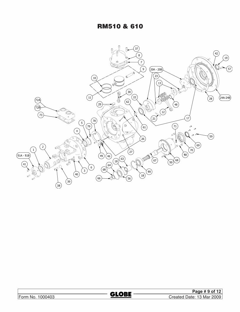
Motors - RM510, RM610Remove bolts (58) holding the output shaft assembly. Remove bolts (57) and the output flange (24A/B). This will then expose the inside of the motor. Remove that cylinder, the retaining circlip and gudgeon pin. Push out from the piston and the entire assembly can be removed. Repeat this procedure in turn until all the pistons and cylinders have been removed. On this motor the balance weight and crank assembly is built as one item and this can now be removed. Remove locking nut (22) and the tapered pin (21). Both balance weights (part no. 20A and 20B) can now be disengaged. This will expose the king rod and queen rod assembly. To remove the queen rod remove the pivot pin (29).
All MotorsInspect for excessive clearance of the pivot pins (29) in queen rod (30) & king rod (12). Inspect the gudgeon pin in both the piston and all rods. Check for wear on the main crankshaft (20A, 20B) and on the main big end bearing (no. 48). Check for excessive wear in the cylinder bores, this can be checked by removing each compression ring (10) and pushing it into the cylinder bore (8). Bore wear will cause loss of power and inject high pressure air into the case & oil could be ejected from the breather plug (part no. 46). All other parts should be thoroughly cleaned and inspected for wear. Spare parts can be found from the list. The motor number and its code should be incorporated in any spares order.
WARNING: Each motor is supplied with a metal nameplate (Identification plate) located on the engine case (27) or rotary valve housing (3). Waranty will not be granted if the namelate is removed.
ASSeMbLy PROceDuReThe remaining build procedure is the reverse to initially dismantling. All parts should be clean and liberally coated with oil.
WARNING: When first running the motor, some light oil should be injected into the inlet connection to ensure ad-equate lubrication until the air line lubrication is established.
Page # 6 of 12 Created Date: 13 Mar 2009 Form No. 1000403
Motors - RM110, RM210, RM310, RM410Output shaft assembly. Ensure both circlips and bearing are fully home. Oilseal (19) lip must face inwards and be lubricated. RM410 motor has also a spacer (47) fitted between bearings. Push crank shaft fully home and locate the spacer washer (15) and circlip (14). Check gap, shim up (16) for minimum end float. Fit new ‘O’ Ring seal (25) and output flange (24) to the engine case (27). Turn motor vertical (shaft downwards).
Crank Assembly Instruction for – RM110, RM210, and RM310Fit the 3 queen rods (30) on to piston assembly (9) and assemble into the cylinder pot (8) complete with gasket (7). Fit piston assembly (9) on to the king rod (12) ensuring gudgeon pin clips are correctly positioned. (RM310 motor). Assemble a ring clamp (dimensions shown on the sketch provided on back page) on to the king rod piston.Fit the crank spacer (13) to the crankshaft (20A/B). Rotate the crankshaft until the crankpin is in the vertical position (nearest the breather plug46). Feed king rod (12) complete with its piston assembly through the aperture marked ‘Z’ on drawing. Twist and lift the rod over the end of the crank pin.Fit crank pin bearing or bearings. Feed the cylinder pot (8) complete with its gasket (7) on to the piston. The ring clamp is ejected inwards from the piston. Work clamp off sideways from the king rod.Bolt the cylinder pot into position and feed the remaining cylinders completely assembled through the various holes and locate the inner end of the connecting rods with the king rod fixing with pin (29).Rotate the motor 360 degrees to ensure correct fitting. Fit spacing washer (30/34) and refer to paragraph 10 for spacing the motor unit.
Assembly of 410 Big EndFit all connecting rods (30) & (12) on to gudgeon pins and pistons and using ring clamp assemble into cylinders. Ensure gudgeon pin ciclips are seated correctly.Rotate motor until crank is nearest to breather plug (46). Fit the crank spacer (13) push the piston to bottom dead center within the cylinder (8). Insert the king rod into the engine case (27) lifting and rotating the king rod (12) over the top of the crankshaft (20A/B). Bolt cylinder in position, fit the 2 crank bearings (48). Fit remaining cylinders/pistons and attach to king rod (12) with the pivot pin (29). Rotate 360 degrees to ensure parts are correctly fitted. Locate the spacing washer (31–34) and spacing as paragraph 10.
Valve Housing AssemblyThis is reverse procedure to dismantling. Smear oil to external surface of valve (2) and to the bore of valve housing (3).
RM510 and RM610 motor onlyAssemble the spacing washer (13) on to the crankshaft outer section locating the dowel pin (23). Assemble bearing (48) and the king rod (12). Assemble all four queen rods (part no. 30) into the king rod (12) locating with pivot pins (no.29). Fit final location washer (13) to close the assembly. Ensure that the dowel pin (23) is fitted on to the inner balance weight (20 A/B). Mount or fit together and locate the 12 mm dia. holes. Once these holes are located, fit the locking dowel (21) and its nut can be assembled, Locate assembly into open engine case. Ensure each rod projects into its correct cylinder. Rotate the unit so that the main king rod comes to top dead center, fit the piston and gudgeon pin, ensure gudgeon pin circlip is correctly located. Fit gasket (7) to cylinder (8). Fit pistons into cylinder bore using a piston ring clamp. Bolt cylinder (8) on to engine case (27). Rotate the crank to the next top dead center position and repeat the procedure. Turn crank 360 degrees to check correct functioning. Fit gasket (28) and the output flange (24A/B). Turn motor over 180 degrees to allow the valve to be fitted. Lubricate Valve (2) & Inside Bore of Housing (3). Rebuild the valve assembly in the reverse order. Check it rotates freely. Fit valve assembly on to the motor ensuing the different size drive dowels (61) and (62) are located in the crank shaft.

Page # 7 of 12 Form No. 1000403 Created Date: 13 Mar 2009
PISTON RINg cLAMP DeTAILS
Spacing RM110, RM210, RM310, RM410 MotorsPlease refer to (Fig. 3) Measure dimension (A) from the crank washer to the face of the engine case and also dimension (B) from the rotary valve face to the inside of the gasket. Select the correct shim washer from the list (31—34) to obtain clearance.Rotate the crankshaft until the balance weight is at the bottom dead center position, rotate the rotary valve until the balance weight is at the bottom position. Assemble the valve housing (3) on to the engine case (27). Rotate the output shaft in both directions and viewing the rotary valve (2) through the exhaust cover (51) ensure that the valve is correctly following the output shaft direction, this checks that both crank and valve slot are correctly engaged.Replace all drain plugs and refill with oil. Spray some light oil into the inlet and exhaust ports and connect the unit to a low pressure supply and allow the unit to run on the bench for a short period of time prior to refitting the unit into full service.
SPAcINg DIAgRAM
W S mm in. mm in. RM110 13 (.5) 27 (1.0) RM210 32 (1.25) 25 (1.0) RM310 45 1.75) 16 (.625) Note: these items can be cut from an old cylinder. (8)
Fit spacing washer such that A-B = 0.25 to 0.50 mm (0.01” to 0.02”) clearance
Crank Spacing Washers RM110 RM210 RM310 RM410 1.85 (.073) 2.64 (.104) 3.24 (.128) 2.5 (.099) 2.03 (.080) 3.25 (.128) 3.66 (.144) 3.0 (.120) 2.34 (.092) 3.66 (.144) 4.06 (.160) 4.0 (.157) 2.64 (.104) Dimensions are in millimeters (and inches)

Page # 8 of 12 Created Date: 13 Mar 2009 Form No. 1000403
TROubLe ShOOTINg
The RM series motors are designed to perform at their rated capacities for long periods of time. Faults can develop for the following reasons:(A) Lack of lubrication. This will lead to rapid wear, internal seizure, loss of power or excessive air leakage.(B) Faults in the air supply system:1. Failure to remove the plastic protective dust caps.2. Insufficient air pressure at the motor caused by (a) supply pipe line or valve too small (b) if the exhaust is piped away excessive back pressure due to small bore pipes (c) compressor of insufficient capacity (d) clogged airline filter (e) the air pressure should remain at the required pressure when the motor is operating at full potential.If the air pressure reduces considerably from the stationary to the rotating conditions then the supply line or the compressed air available is inadequate for the service operation of the motor.
The motor should always be supplied with clean moisture-free and lubricated air. The better the quality of air, the less attention will be required to the motor unit.
MOTOR exPLODeD vIewS
RM110–410
Page # 9 of 12 Form No. 1000403 Created Date: 13 Mar 2009
RM510 & 610
72A
72B
38

Page # 10 of 12 Created Date: 13 Mar 2009 Form No. 1000403
PARTS LIST
Item Description No 110 210 310 410 510 610 1 Rotary Valve Bearing (outer) 1 807-020 807-020 807-002 807-006 807-006 807-0562 Rotary Valve 1 130-006 230-059 330-059 430-006 520-006 620-006 3 Rotary Valve Housing 1 130-011 230-011 330-011 430-011 520-011 620-011 4 Rotary Valve Bearing (inner) 1 807-021 807-021 807-001 807-005 807-005 807-055 5 Rotary Valve Bearing Circlip 1 804-051 804-051 804-054 804-066 804-066 804-070 6 Rotary Valve Housing Gasket 1* 100-001 200-001 300-001 ‘ 430-001 510-001 620-0017 Cylinder Gasket 4-5* 110-030 210-030 310-030 430-030 510-030 510-030 8 Cylinder 4-5 110-082 210-082 310-082 430-082 510-082 510-082 9 Piston Assembly 4-5 130-902 230-902A 330-902A 430-902A 520-902A 520-902A 10 Compression Ring 4-5* 100-024 200-024 300-024 430-024 520-024 520-024 11 Oil Control Ring 4-5* 100-022 200-022 300-022 430-022 520-022 520-02212 King Rod 1 140-077 230-077 320-077 430-077 520-077 520-07713 Crankshaft Spacer 1 140-013 230-013 320-013 430-053 520-052 520-052 14 Crankshaft Circlip 1 804-006 804-009 804-012 804-016 — — 15 Crankshaft Spacer 1 100-035 300-035 310-035 430-035 — — 16 Crankshaft Spacer Shim 5 100-049 300-049 310-049 430-049 — — 17 Crankshaft Bearing 2 — — — — 807-062 807-062 18 Crankshaft Bearing Circlip 2 804-051 804-058 804-062 804-068 804-068 804-068 19 Crankshaft Oilseal 1* 808-043 808-044 808-045 808-048 808-047 808-047 20A Std Crankshaft Assembly 1 110-901 230-915 330-911 430-901 520-901 520-901 20B SAE Crankshaft Assembly — — — 430-904 520-904 520-904 21 Crank Bolt 1 — — — — 510-088 510-088 22 Crank Nut 1 — — — — 801-009 801-009 23 Spring Dowel 2 — — — — 806-013 806-01 3 24A Std Flange Plate 1 130-076 230-076 330-076 430-076 520-076 520-076 24B SAE Flange Plate 1 — — — 430-097 520-113 520-113 25 Flange Plate Seal 1* 808-033 808-028 808-026 808-018 — — 26 Plug 1-3 816-074 816-071 816-071 816-071 816-071 816-071 27 Engine Case 1 130-012 230-012 330-012 430-012 520-012 620-012 28 Engine Case Gasket (520) 1* — — — — 510-090 510-090 29 Queen Rod Pivot 3-4 140-081 230-081 320-081 430-081 520-081 520-081 30 Queen Rod 4 140-078 230-078 330-078 430-078 520-078 520-078 31 Crank Spacer SELECT 1s 140-052 230-052 320-052 430-052 — — 32 Crank Spacer ON 1s 140-053 — 320-053 430-053 — — 33 Crank Spacer ASSEMBLY 1s 140-054 /055 230-054 320-054 430-054 — — 34 Crank Spacer 1s 140-056 230-056 — — — — 35 Balance Weight 1 130-010 230-010 330-010 430-010 — — 36 Woodruff Key 1 811-016 811-010 811-010 811-009 — — 37 Cylinder Bolts 16-20 802-020 802-032 802-053 802-054 809-035 809-035 Note 1 Items marked thus s select on assembly Note 2 Please note Item 76 (Seal Kit) includes all items marked thus: *

Page # 11 of 12 Form No. 1000403 Created Date: 13 Mar 2009
Item Description No 110 210 310 410 510 610 38 Valve Housing Bolts 4-10 802-020 802-033 802-053 802-054 802-073 802-05439 Washer for item 38 4-10 — — — 803-015 803-00140 Adapter Plate Bolts 4 802-020 802-020 802-032 802-054 802-054 809-00241 Exhaust Cover Bolts 2-4 802-016 802-016 802-032 802-033 802-033 802-03342 Flange Plate Plugs 5 — — — — 815-008 815-00844 Dipstick (vertical mounting) 1 100-040 200-040 300-040 — — —45 Seal (transit only) 1 808-004 808-004 808-004 808-004 808-004 808-00446 Breather Plug 1 130-066 130-066 130-066 130-066 130-066 130-06647 Oil Seal Carrier 1 — — — 430-083 — —48 Needle Bearing 1-2 807-042 807-048 807-065 807-045 807-047 807-04749 Grub Screw 1-5 815-012 815-001 815-002 815-003 — —50 Key 1 811-002 811-001 811-003 811-005 811-030 811-03051A Rotary Valve Exhaust Cover BSP 1 130-005 230-005 330-005 430-005 520-005 620-04251B Rotary Valve Exhaust Cover NPT 1 130-105 230-105 330-105 430-105 520-105 620-042N52 Flange Bolts 4-8 810-003 810-001 810-002 809-001 — —55 Output Shaft Bearing (outer) 1 807-007 807-008 807-009 807-013 807-063 807-06356 Output Shaft Bearing (inner) 1 807-007 807-008 807-009 807-012 807-012 807-01257 Flange Plate Cap Screws 10 — — — — 809-001 809-00158 Output Housing bolts 5 — — — — 809-002 809-00259 Output Housing Cover Bolts 5 — — — — 802-016 802-01660 Oil Level Plug 1 816-063 816-063 816-063 816-074 — —61 Drive Pin (dia. 10mm) 1 — — — — 806-001 806-00162 Drive Pin (dia. 12mm) 1 — — — — 806-002 806-00263 Output Shaft Bearing Spacer 1 — — — — 518-001 518-00164 Output Shaft Spring Ring 1 — — — — 518-004 518-00465 Output Shaft Circlip 1 — — — — 804-017 804-01766 Output Shaft Seal 1* — — — — 808-004 808-00467 Output Shaft 1 — — — — 518-003 518-00368 Output Shaft Housing 1 — — — — 518-005 518-00569 Output Shaft Oil Seal 1* — — — — 808-042 808-04270 Output Shaft Housing Cover 1 — — — — 518-002 518-00271 Output Shaft Grease Nipple 1 — — — — 816-015 816-01572A Inlet Adapter Plate BSP 1 130-003 230-003 330-003 430-003 520-003 620-04672B Inlet Adapter Plate NPT 1 130-103 230-103 330-103 430-103 520-103 620-046N73 Inlet Adapter Plate Gasket 1* 130-004 130-004 330-004 430-004 430-004 620-04775 Dipstick Seal 1* 808-008 808-008 808-008 — — —76 Seal Kit 1 139-911 239-911 339-911 439-910 529-911 629-91278 Bearing Cap 1 — — — — — 620-04579 Bearing Cap C’sk Screw 4 — — — — — 810-01680 Rotary Valve Spacer 2 — 230-060 330-060 — — — Connecting Rod (slipper type) 1 149-920 CONVERSION KIT Note 1 Items marked thus s select on assembly Note 2 Please note Item 76 (Seal Kit) includes all items marked thus: *
PARTS LIST

Page # 12 of 12 Created Date: 13 Mar 2009 Form No. 1000403
© Copyright 2009 SPX Hydraulic Technologies, All rights reserved.
Every effort has been made to assure the accuracy of product descriptions in this catalog at the time of printing. SPX Hydraulic Technologies reserves the right to modify or discontinue products without prior notice.
The Americas World Headquarters
Customer Service CenterTEL 800-541-1418FAX 800-288-7031 EMAIL [email protected] 11th St.Rockford, Illinois 61109 USATEL +1 815-874-5556
Europe
Customer Service CenterTEL +31 45 5678877FAX +31 45 5678878EMAIL [email protected] Albert Thijsstraat 126471 WX EygelshovenThe Netherlands
Asia Pacific
Customer Service CenterTEL +65 6265 3343FAX +65 6265 6646EMAIL infoasia@ globeairmotors.com 7 Gul CircleSingapore 629563Singapore
China
Customer Service CenterTEL +86 21 2208 5888FAX +86 21 2208 5682EMAIL infochina@ globeairmotors.com No. 1568 Hua Shan RoadInternational Park Center9th FloorShanghai 200052China
II 2 GD cT5