radarpilot 1100 brilliant colour radars - themys · 2016-04-05 · introduction the radarpilot 1100...
TRANSCRIPT

RADARPILOT 1100
Brilliant Colour Radars
Com
pliant
with new
IMO 2008 regulations

Introduction
The RADARPILOT 1100 represents a milestone in technical performance, ease of operation, simple maintenance and future oriented system technology.
■ Easy to operate by means of trackball■ Compliant with new IMO class 1, 2
and 3 radars■ Wide range of console and desktop
options■ Wide choice of X- and S-band trans-
ceivers (bulkhead or aloft)■ Two antenna speeds for high speed
operations (HSC)*■ Integrated 2-way radar interswitch
■ CLEAN SWEEP for automatic suppression of clutter
■ Extra window for radarscope, echo-sounder, wind or docking display
■ Display of own chart user objects which are created on the CHARTPILOT 1100
■ High resolution colour graphics and monitors provide a clear and distinct radar presentation
■ Display of pre-planned routes ■ Two metric docking ranges■ Integrated Automatic Steering and
Track Control for TRACKPILOT 1100 (in case of NACOS xx-5 only)
■ Display of NAVTEX messages■ Tracking of 80 ARPA/AIS targets■ Display of 400 AIS sleeping targets■ ARPA/AIS target association function■ Full operation as minimum keyboard
display for AIS 3400/10■ Optional remote access e.g. for wing
operation to master each display from any of up to 4 slave stations
■ Full operation of Voyage Data Recorder DEGEG 4300 including radar recording
* The high antenna rotation is available with three phase power supply only
2

Innovative Solutions
The RADARPILOT 1100 sets a new
milestone in marine radars. Decades
of experience combined with the
latest technology open up new
dimensions of practical use.
■ Take advantage of high resolution graphic performance for clear radar presentation and easy target recognition
■ Suppress radar interference from rain or sea clutter simply with the CLEAN SWEEP function: AVE (Automatic Video Enhancement) is now a standard feature
■ Experience the advantage of modern graphic processors: Target trails are automatically adopted to signal strength and are not lost even if they are changed in presentation or length
■ Make use of intelligent functions for economic and safe navigation, e.g. the novel DOCKING MODE which is implemented in special 250 and 500 mrange scales. The additional docking function will assist you with a graphic display of bow and stern distances and speed to the pier
■ Switch to high speed antenna rotation1),this is advantageous for high speed ship operations and improves the display refresh rate for better target recognition
■ Access user-friendly navigation func-tion for route planning with courses, safety contours, traffic separation lines and chart symbols
■ Observe an enlarged cut-out of the RADARSCOPE function in a separate display window. Or use this for graphic display of wind, depth or docking data
■ In combination with DEBEG 2902 NAVTEX messages will be directly reported to the radar and displayed onuser demand
■ If connected to the VDR DEBEG 4300the internal network of the RADAR-PILOT allows direct recording of the radar image
■ In combination with the AIS 3400/10 the RADARPILOT supports full AIS operation, which saves the costs for an extra Minimum Keyboard Display
The mechanical housing concept of theRADARPILOT 1100 is very flexible:■ Choice between desktop and console versions■ The monitor and control panel components
can also be supplied as individual units for integration into a customer specific console
3

Individual brightness settings inclu-ding choice of 6 colour tables
Access to mapping functions
Alarm symbol
for calling-up of alarm messages
Radarscope window with display options:- Radar-zoom fixed to a tracked target
or to a certain position- Graphic display of wind or depth profile- Docking display- AIS data display- Radar map operation menu- Alarm list
Data of on-screen cursor position or own ship’s position and sensor in use
TRACKPILOT (Option NACOS) forHeading, Course- or Track Control
Speed
Heading
Data display for:- Full tracked data for two marked targets- Short readout of up to 8 targets- Waypoint data- Track data
The Radarscope window may alternativelydisplay WIND or DEPTH graphics, if therespective sensors are connected.In the DOCKING mode the 2nd EBL may beused to establish the initial distances fromthe bow and stern to a berth.After defining the reference positions of the ship’s contour, the RADARPILOT continuously displays the actual distanceand speed values based on the input of the (D) GPS receiver.
WIND display
DOCKING display
DEPTH display
TRACKPILOT control panelwith joystick
TRACKBALL for left- orright-hand operation
The Trackball includes a large DO button for activating operator settings.Either one or the two smaller buttons may be used for additional functions.
Quick info box
for display of:- ETA to cursor position- operator instructions- Date / Time- Stop watch
Access to track and route planningfunctions
5
RADARPILOT 1100
Display of AIS dataand symbology
Interswitching of antennas- for dual installations
(via built-in interswitch)- for multiple installations with up
to 5 transceivers/displays(via optional PCI interswitch)
CLEAN SWEEP
Anti-Clutter Optimisation with AVE(Automatic Video Enhancement)
Interference Rejection
Simple maps and symbols can becreated by using the radar map editor.If connected to the CHARTPILOTown chart objects can be transferredvia LAN to the radar
4 Parallel Index Lines (PI)
for manoeuvre planning
2 Independent EBL and VRM
adjustable individually or combineddirectly within the PPI or via rotaryknobs of the optional keyboard
The Trackball is the main operationalelement. The active field is marked bya frame. A quick info box shows theavailable operational functions for thetrackball buttons. Optional controlpanels can be integrated for operatingthe Radar or TRACKPILOT
Control of the display mode Head Up and North Up or RM and TM
Control of the Radar PPI e.g. display rangesmay be selected from 0.25 to 96 NM or forDOCKING as 250 or 500m
PATH Prediction
allows the operatorto display a changeof heading via con-stant radius turn
Display and storingof EVENT data. PRINT screen
function via CHARTPILOT 1100
Trails are not lost despite of changing parameters
4
Selection of Consistent Common
Reference Point (CCRP)
Radar CAN 0
Radar CAN 1
LAN
TVA
GPS VHF
Voyage DataRecorder
Navigation Data
Final Recording Medium
Position
Heading
Speed
SAM SAM
The optional TRACKPILOT control panelis used when the RADARPILOT
is part of a NACOS system
The optional radar control panelallows baisc radar operations with
traditional push buttons androtary controls
The interfaces in a dualinstallation can either beused for redundant or foradditional sensor connections
RADAR DISPLAYELECTRONICS UNIT
RGB Video Interface
Analog Interface
Serial Interface
Ethernet Interface
AIS Interface
Central Alarm Panel
RADAR DISPLAYELECTRONICS UNIT
RGB Video Interface
Analog Interface
Serial Interface
Ethernet Interface
AIS Interface
Central Alarm Panel
VOYAGEDATA RECORDER
DEBEG 4300
Wind
Depth
Alarm
RGG Video out
AISTRANSPONDER UNIT
AIS 3400/10
Turning Unitwith integrated 12.5/25 kW X-Band
or 30 kW S-Band Transceiver(optional bulkhead transceiver)
Scanner5 or 8 ft. X-Band Antenna
14 ft. S-Band Antenna
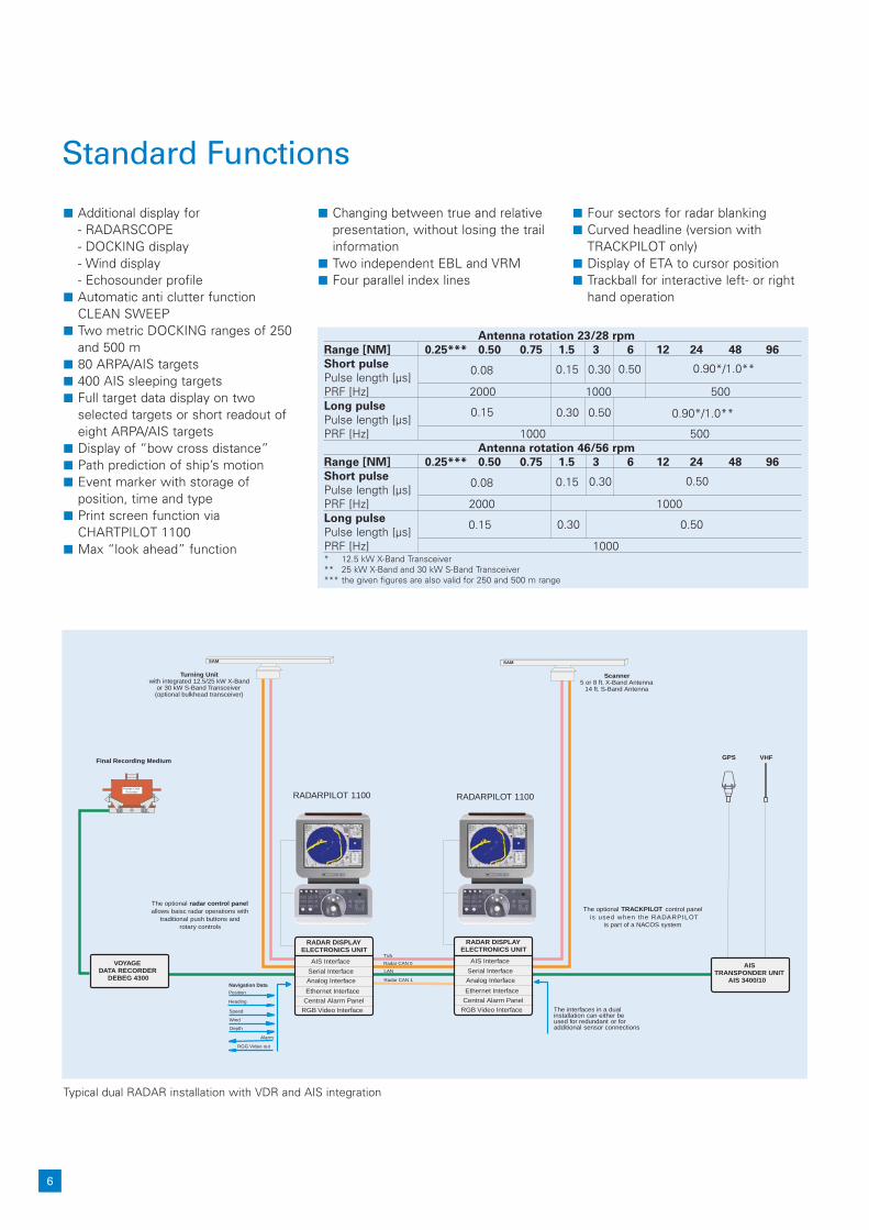
■ Additional display for- RADARSCOPE- DOCKING display- Wind display- Echosounder profile
■ Automatic anti clutter functionCLEAN SWEEP
■ Two metric DOCKING ranges of 250 and 500 m
■ 80 ARPA/AIS targets■ 400 AIS sleeping targets■ Full target data display on two
selected targets or short readout of eight ARPA/AIS targets
■ Display of “bow cross distance”■ Path prediction of ship’s motion■ Event marker with storage of
position, time and type■ Print screen function via
CHARTPILOT 1100■ Max “look ahead” function
Standard Functions
Typical dual RADAR installation with VDR and AIS integration
■ Changing between true and relative presentation, without losing the trail information
■ Two independent EBL and VRM■ Four parallel index lines
■ Four sectors for radar blanking■ Curved headline (version with
TRACKPILOT only)■ Display of ETA to cursor position■ Trackball for interactive left- or right
hand operation
Antenna rotation 23/28 rpm
Range [NM] 0.25*** 0.50 0.75 1.5 3 6 12 24 48 96
Short pulse
Pulse length [µs]PRF [Hz] 2000 1000 500Long pulse
Pulse length [µs]PRF [Hz] 1000 500
Antenna rotation 46/56 rpm
Range [NM] 0.25*** 0.50 0.75 1.5 3 6 12 24 48 96
Short pulse
Pulse length [µs]PRF [Hz] 2000 1000Long pulse
Pulse length [µs]PRF [Hz] 1000* 12.5 kW X-Band Transceiver** 25 kW X-Band and 30 kW S-Band Transceiver*** the given figures are also valid for 250 and 500 m range
0.08 0.15 0.30 0.50 0.90*/1.0**
0.15 0.30 0.50 0.90*/1.0**
0.08 0.15 0.30 0.50
0.15 0.30 0.50
6
RADARPILOT 1100 RADARPILOT 1100

Technical and Installation Data
x y
C5 Console unit with integrated control panel and
display electronics
C5 Desktop unit with
integrated control panel
C5 Desktop monitor
without control panel
C5 Console monitor
x x
y
z z
y
x
y
x y
C4 Console unit with integrated control panel and
display electronics
Weight: 95/72 kg
Weight: 81/74 kgWeight: 40/33 kg
Weight: 35/28 kg
Weight: 17/14 kg
C4 Console monitor C4 Desktop monitor
7
z
zz
RADARPILOT 1100 basic versions
Dimensions [mm]Characteristics C5 Console unit C5 Desktop unit C5 Desktop monitor C5 Console monitor
Category Size x y z x y z x y z x y zCAT 2 19“ TFT 650 887 1085 516 690 432 516 344 436 515 88 441CAT 1 23“ TFT 650 887 1168 630 690 516 630 344 519 630 102 534
RADARPILOT 1100 basic versions
Dimensions [mm]Characteristics C4 Console unit C4 Console monitor C4 Desktop monitor
Category Size x y z x y z x y zCAT 2 19“ TFT 550 1090 1150 483 82 404 489 130 493CAT 1 23“ TFT 700 1090 1150 584 97 495 615 130 576
520
360
275
Weight: 10.5 kg
Display electronics Control panels
Trackball Trackball with radar panel
Trackball withradar/trackpilot panel
Trackball
x y
z
x
z
y

6
Prin
ted
in G
erm
any
· Tec
hnic
al a
ltera
tions
res
erve
d · ©
SA
M E
lect
roni
cs G
mbH
· D
S 3
.051
.09/
2008
SAM Electronics GmbHAutomation, Navigation and CommunicationBehringstrasse 12022763 Hamburg . Germany
Phone: +49 - (0)40 - 88 25 - 24 84Fax: +49 - (0)40 - 88 25 - 41 [email protected]
Technical and Installation Data
S-Band Antenna Unit, Type GR3041, with integrated performancemonitor and 30 kW* S-Band transceiver, optional 30kW* bulkhead transceiver, type NG3041
X-Band Antenna Unit, Type GR3040, with integrated performancemonitor and 12.5 or 25 kW* X-Band transceiver, optional 25 kW* bulkhead transceiver, type NG3040
Beamwidth: 8 ft. 5 ft.Horizontal 0.9° 1.5°Vertical 21° 23°
Weight: 60/64 kg
Operational conditions and protection (according to IEC 60945, extract): below deck units:max. -15°C to +55°C (for reasons of lifetime, a constant ambient temperature of approx.20°C, ±5°C should be maintained) above deck units: max. -25°C to +55°C (+70°C for storage)
Bulkhead transceiver, type NG3040(X-Band) and NG3041 (S-Band)
Beamwidth: 14 ft.Horizontal: 1.7°Vertical 21°
Weight: 198 kg
Weight:: 16/20 Kg (X/S-Band)
600 (X-Band) 800 (S-Band)
235
1x 1x 3x 3x 3x PowerAC voltage** 115 V 230 V 230 V 400 V 450 V Cons. HSCfrequency 60 Hz 50/60 Hz 50/60 Hz 50/60 Hz 60 Hz [VA] ModeX-Band antenna unit,
• • • • 250/460*** •type GR 3040S-Band antenna unit,
• • • • 1300/1700*** •type GR 3041X/S-Band transceiver,
• • 150type NG3040/41* Magnetron peak power (nominal)** Tolerances according to IEC 60945*** The higher consumption only applies to high speed antenna units
4220 (14ft.)
440
700
835
1689 (5 ft.)2585 (8 ft.)
300
405475
548
575
500 (X-Band)600 (S-Band)