radar and navigational aids jayaraman (1053) kaushik (1059) ikram (3009) vignesh (3010)
TRANSCRIPT
Types Of Mixers In Radar Receivers
Radar And Navigational Aids
Jayaraman (1053)Kaushik (1059)Ikram (3009)Vignesh (3010)
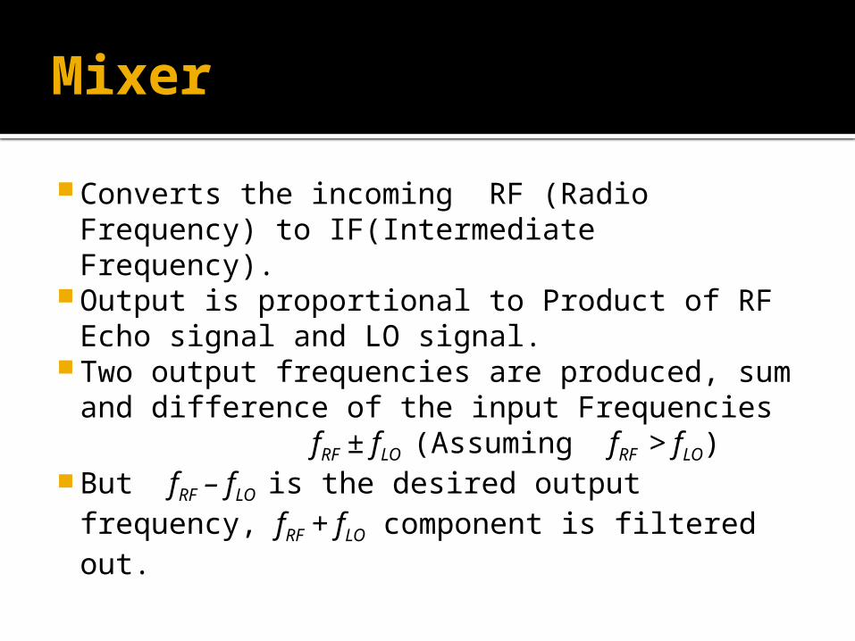
Mixer
Converts the incoming RF (Radio Frequency) to IF(Intermediate Frequency).
Output is proportional to Product of RF Echo signal and LO signal.
Two output frequencies are produced, sum and difference of the input Frequencies fRF ± fLO (Assuming fRF > fLO)
But fRF – fLO is the desired output frequency, fRF + fLO component is filtered out.
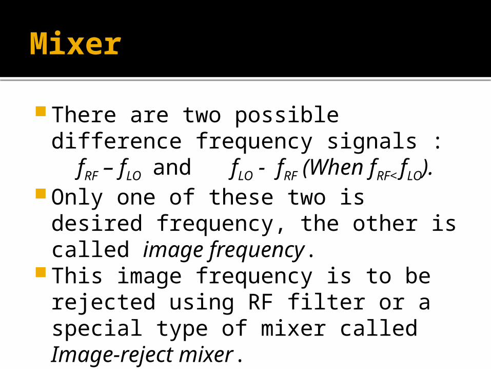
Mixer
There are two possible difference frequency signals : fRF – fLO and fLO - fRF (When fRF<
fLO). Only one of these two is desired frequency,
the other is called image frequency. This image frequency is to be rejected using
RF filter or a special type of mixer called Image-reject mixer.
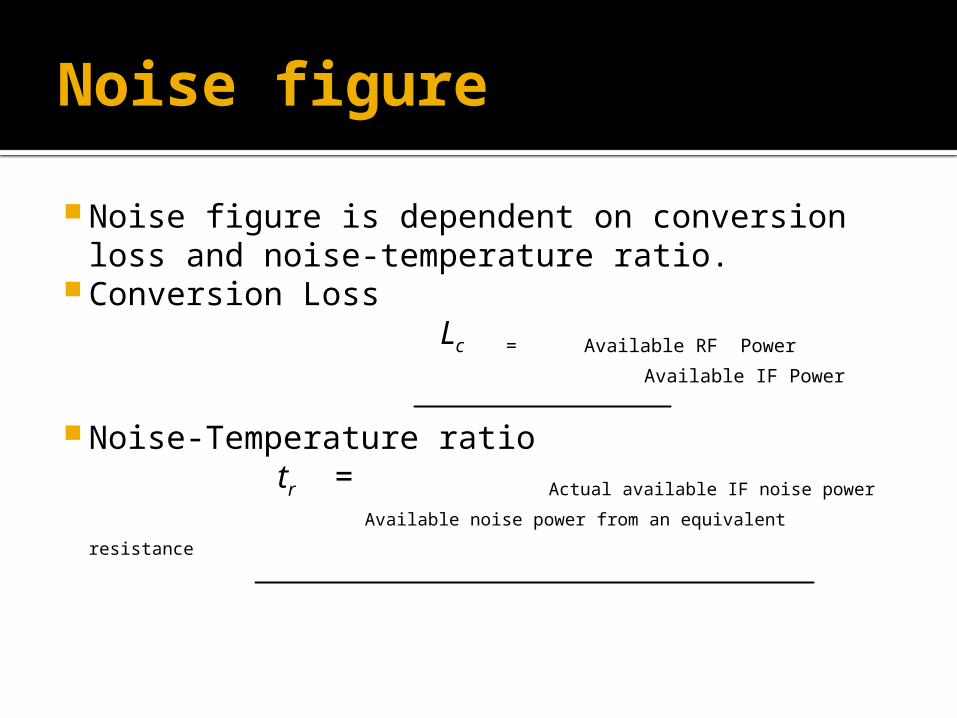
Noise figure
Noise figure is dependent on conversion loss and noise-temperature ratio.
Conversion Loss
Lc = Available RF Power
Available IF Power
Noise-Temperature ratio tr = Actual available IF noise power
Available noise power from an equivalent resistance
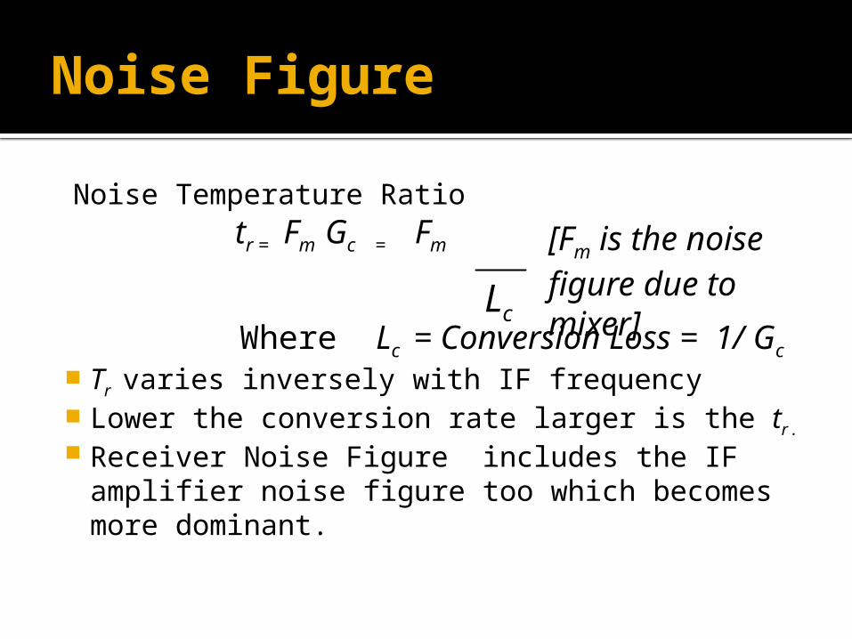
Noise Figure
Noise Temperature Ratio tr = Fm Gc = Fm
Where Lc = Conversion Loss = 1/ Gc
Tr varies inversely with IF frequency Lower the conversion rate larger is the tr .
Receiver Noise Figure includes the IF amplifier noise figure too which becomes more dominant.
Lc
[Fm is the noise figure due to mixer]
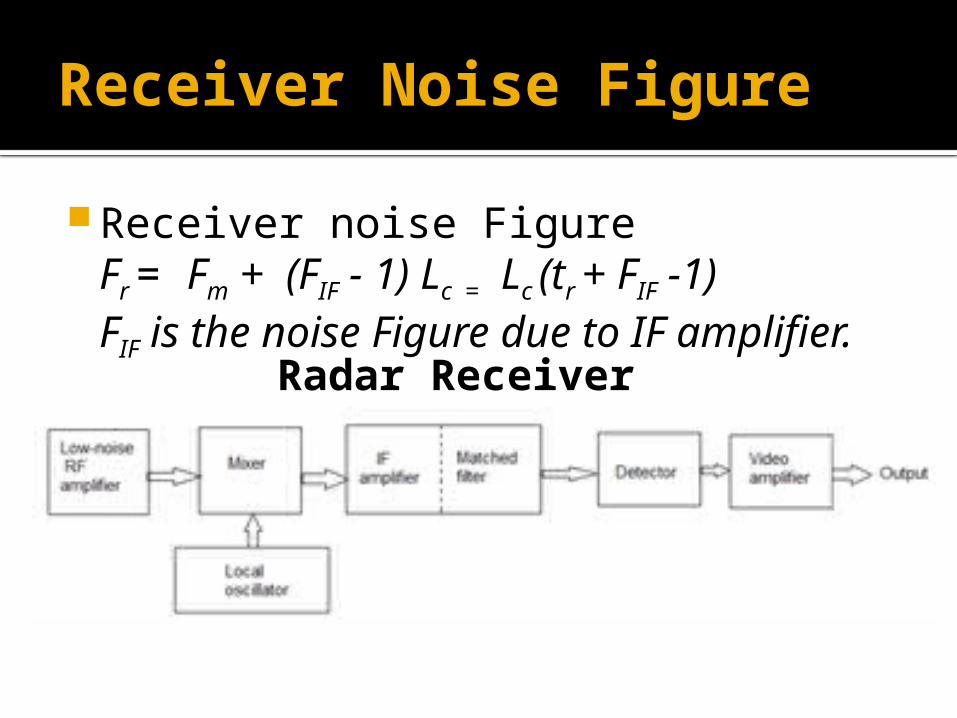
Receiver Noise Figure
Receiver noise Figure Fr = Fm + (FIF - 1) Lc = Lc (tr + FIF -1) FIF is the noise Figure due to IF amplifier.
Radar Receiver
Ideal Mixer
An ideal mixer must possess the following characters
Low conversion loss,
Minimized spurious responses,
Should not be susceptible to burnout,
Large noise-temperature ratio.
Types of Mixers
1. Single-ended Mixer
2. Balanced Mixer
3. Double- balanced Mixer
4. Image-rejection Mixer
5. Image-recovery Mixer
Single-ended Mixer
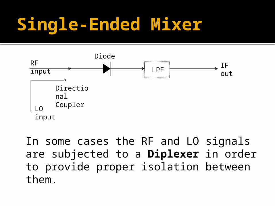
Also called as an unbalanced or crystal mixer.
Uses a single diode that terminates a transmission line, LO is inserted via a directional coupler.
An LPF after the diode filters out RF and LO signals allowing only IF.
The unwanted Image frequency is short circuited or Open circuited.
Single-ended Mixer
Diode being a non-linear device produces inter-modulation products, called Spurious responses. (When mfRF + nfLO = fIF )
Taylor proposed a mixer chart to determine the RF and LO frequencies that are free from spurious responses.
A Mixer chart is a graphical representation of wanted and unwanted (spurious) mixing products in-band and out-of-band.
Single-Ended Mixer
Presence of two or more RF signals also results in spurious responses.
LO noise is to be removed by an RF filter between LO and Mixer.
Single conversion receivers suppress these spurious responses.
Single-Ended Mixer
LPFIF outRF input
LO input
Directional Coupler
Diode
In some cases the RF and LO signals are subjected to a Diplexer in order to provide proper isolation between them.
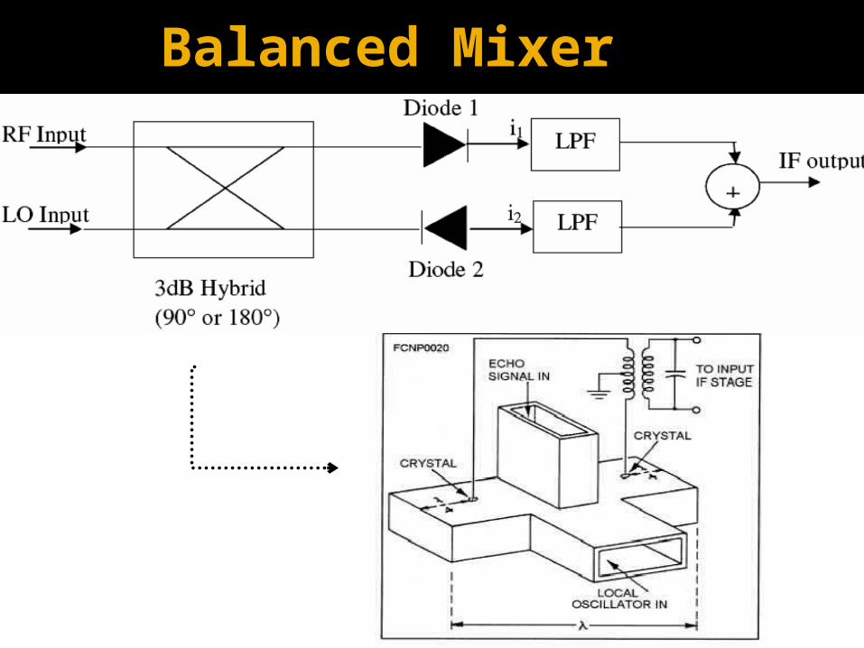
Balanced Mixer
Two single ended mixer in parallel and 180o
out of phase. A 4-port junction such as magic-T, hybrid
junction or 3dB coupler is used. LO and RF signals are applied at ports 1 and
2, their sum and difference is obtained at ports 3 and 4.
Diode mixers are present at ports output of ports 3 & 4.
Balanced Mixer
Balanced Mixer
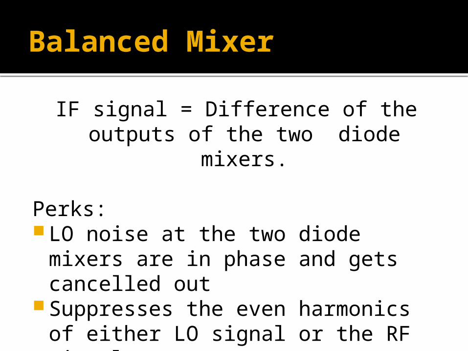
IF signal = Difference of the outputs of the two diode mixers.
Perks: LO noise at the two diode mixers are in phase
and gets cancelled out Suppresses the even harmonics of either LO
signal or the RF signals.
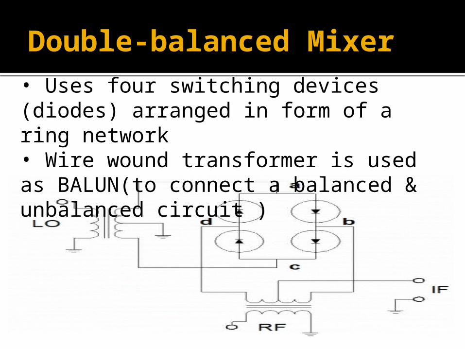
Double-balanced Mixer• Uses four switching devices (diodes) arranged in form of a ring network • Wire wound transformer is used as BALUN(to connect a balanced & unbalanced circuit )
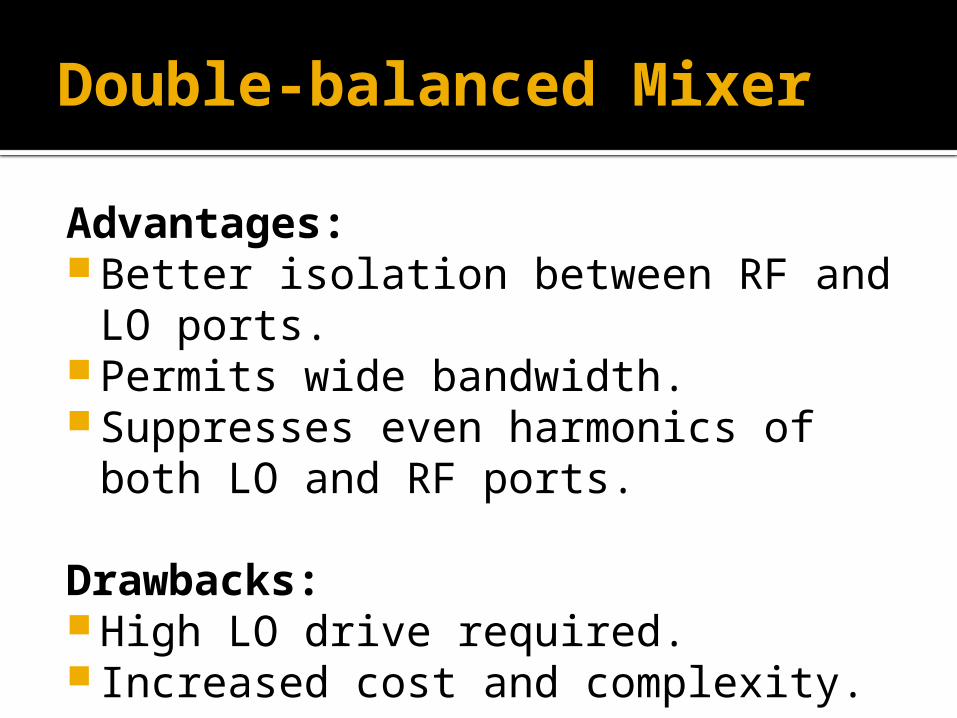
Double-balanced Mixer
Advantages: Better isolation between RF and LO ports. Permits wide bandwidth. Suppresses even harmonics of both LO and
RF ports.
Drawbacks: High LO drive required. Increased cost and complexity.
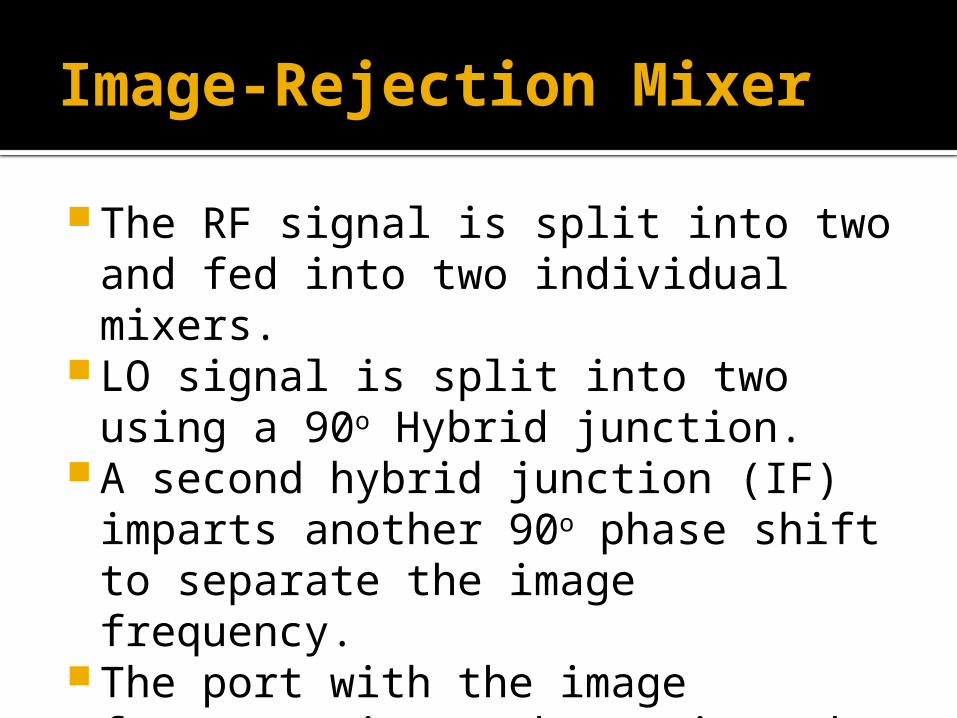
Image-Rejection Mixer
The RF signal is split into two and fed into two individual mixers.
LO signal is split into two using a 90o Hybrid junction.
A second hybrid junction (IF) imparts another 90o phase shift to separate the image frequency.
The port with the image frequency is match terminated.
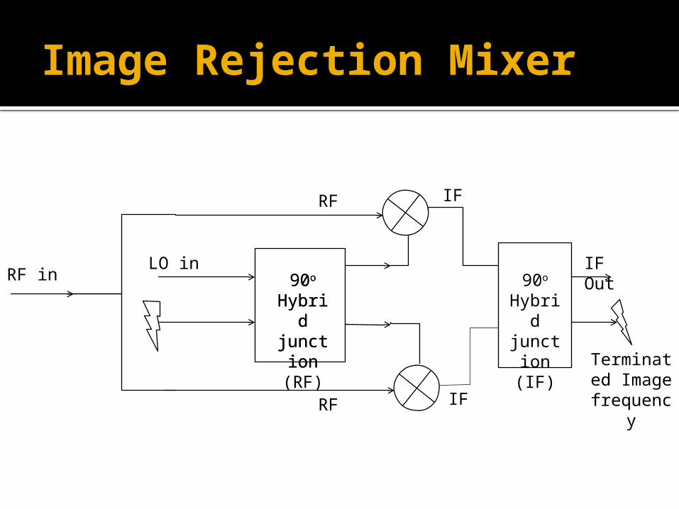
Image Rejection Mixer
RF inLO in
90o Hybrid junctio
n(RF)
90o Hybrid junctio
n(IF)
90o Hybrid junctio
n
RF
RF
IF Out
Terminated Image
frequency
IF
IF
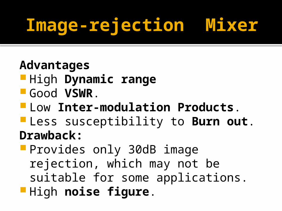
Image-rejection Mixer
Advantages High Dynamic range Good VSWR. Low Inter-modulation Products. Less susceptibility to Burn out.Drawback: Provides only 30dB image rejection, which may
not be suitable for some applications. High noise figure.
Image Rejection Mixer
Dynamic Range of a radar receiver is the Ratio of max input signal power to minimum input signal power without degradation in performance.
Third order modulation product affects the dynamic range of radar.
Third-order distortion products are produced by a nonlinear device when two tones closely spaced in frequency are fed into its input
Image-recovery Mixer / Image-Enhanced
It is a modified version of Image-rejection mixer.
Mixer conversion loss is reduced by terminating a diode in a reactance at the image frequency.
The improvement using this image enhancement is as low as 1 or 2 dB.
Band pass filtering around the input source prevents the image frequency from entering into the mixer again.
Reference
INTRODUCTION TO RADAR SYSTEMS, 3rd Edition, Meril.L.Skolnik.
Practical RF Circuit Design for Modern Wireless Systems, Volume 2 By Rowan Gilmore, Les Besser.
http://www.microwaves101.com/
http://www.radartutorial.eu/
Mixer Basics Primer A Tutorial for RF & Microwave Mixers by: Ferenc Marki & Christopher Marki, Ph.D